INSTRUCTION MANUAL
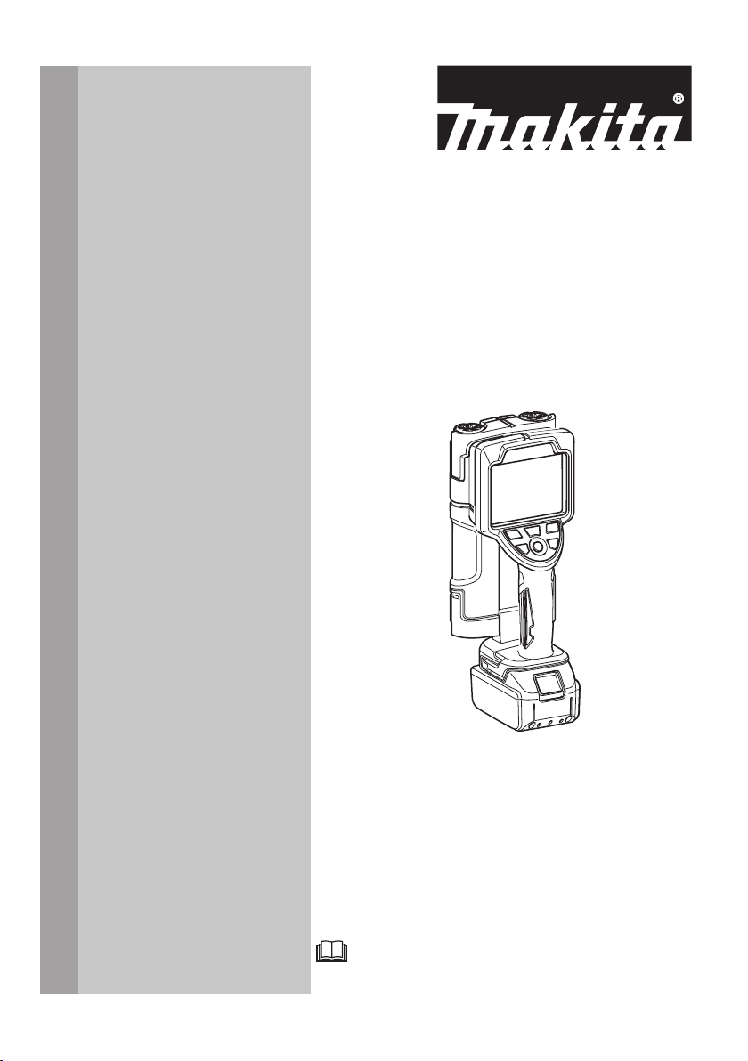
Rechargeable Wall Scanner
DWD181
ENGLISH: Original instructions
Read before use.

2
Contents
Specications ---------------------------------------------------3
Applicable battery cartridge -------------------------------------4
Continuous operating time per one time of charge (*) --------------4
Symbols --------------------------------------------------------5
Intended Use ----------------------------------------------------5
Laser Beam Related Safety Standards -----------------------------6
Safety Declaration -----------------------------------------------6
Radio Standards -------------------------------------------------6
Déclaration sur la sécurité ----------------------------------------9
Normes radioélectriques ------------------------------------------9
Safety Warnings ------------------------------------------------12
Important Safety Instructions for Battery Cartridge ------------------18
Tips for maintaining maximum battery life ------------------------19
Names of Parts -------------------------------------------------20
Names of exterior parts ----------------------------------------20
Names of operation buttons ------------------------------------21
Standard Accessories -------------------------------------------21
Optional Accessories --------------------------------------------22
Battery --------------------------------------------------------23
Battery -------------------------------------------------------23
For long battery life --------------------------------------------23
Installing or Removing Battery Cartridge --------------------------24
Using the Wall Scanner -----------------------------------------25
Operation ow ------------------------------------------------25
Startup ------------------------------------------------------26
Selecting a scan mode ----------------------------------------27
Selecting a scene ---------------------------------------------28
Scanning- - - - - - - - - - - - - - - - - - - - - - - - - - - - - - - - - - - - - - - - - - - - - - - - - - - - - 30
Scan result display --------------------------------------------32
Marking the locations of buried objects --------------------------34
Shutdown ----------------------------------------------------35
Settings -------------------------------------------------------36
Operation ------------------------------------------------------39
Searching for iron bars in concrete ------------------------------39
Searching for wiring resin pipes in concrete ----------------------41
Searching for a pillar behind a gypsum board --------------------46
Searching for iron bars in a block fence --------------------------48
To scan better ------------------------------------------------51
Protection System ----------------------------------------------55
Protective functions for the scanner and the battery ---------------55
Maintenance ---------------------------------------------------57
Care of the product --------------------------------------------57
3
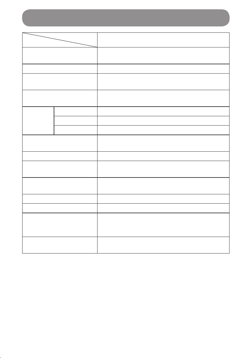
Specications
Model
Major function DWD181
Voltage 14.4 V DC/
18 V DC
Maximum scan depth 180 mm (7 1/16") (*1)
Accuracy of depth to
object ± 5 mm (3/16") (*1, *2)
Minimum detectable
object-object distance 40 mm (1 9/16") (*1)
Scan
guide
laser
Light source Red semiconductor laser
Wavelength 645–660 nm
Optical output 0.39 mW or below (Class 1)
Operational frequency
band 732.76 MHz – 2,881.78 MHz
Transmit power -17.16 dBm
Operating temperature
range -10 °C to + 40 °C (14 °F to 104 °F)
Storage temperature
range -20 °C to + 50 °C (-4 °F to 122 °F)
Relative Humidity 5–60% (Condensation not allowed)
ESD protective measures Level: 4 (IEC61000-4-2)
Product dimensions
(L × W × H)
259 mm × 118 mm × 107 mm
(10 3/16" × 4 5/8" × 4 3/16")
(Except the battery)
Weight 1.0 kg (2.2 lbs)
(Except the battery)
Operating environment: Indoor use
Altitude: Up to 2,000 m (6,561 11/16')
Pollution degree: 2
*1 Varies by the size, shape and material of the buried material, as well as
the material, condition and internal structure of the scanned wall.
*2 When an iron bar of 150 mm (5 15/16") is detected in concrete

4
Applicable battery cartridge
BL1415N/BL1430B/BL1460B/BL1815N/BL1820B/BL1830B/BL1840B/
BL1850B/BL1860B
•Some of the battery cartridges listed above may not be available depending
on your region of residence.
WARNING
Only use the battery cartridges listed above.
• Use of any other battery cartridges may cause injury and/or re.
Continuous operating time per one time of charge (*)
Model
Battery DWD181
BL1860B Approx. 28 hours
• Major functions, shapes and other specications are subject to change for
improvement.
(*) The continuous operating time is for reference purposes. It varies by the
battery's charge status and the operating environment.
5
The denitions below describe the level of severity for each signal word and
the meaning of each symbol used in this manual.
Please read the manual and pay attention to these symbols.
: Read instruction manual.
DANGER : This indicates the risk of death or frequent serious injury.
WARNING : This indicates the risk of serious injury.
CAUTION : This indicates the risk of light injury.
NOTICE
NOTE :This indicates the risk of malfunction or damage to property.
: This indicates the risk of electric shock.
:This indicates the risk of re.
:Laser warning
: Only for EU countries Do not dispose of electric equipment
or battery pack together with household waste material! In
observance of the European Directives, on Waste Electric
and Electronic Equipment and Batteries and Accumulators
and Waste Batteries and Accumulators and their
implementation in accordance with national laws, electric
equipment and batteries and battery pack(s) that have
reached the end of their life must be collected separately
and returned to an environmentally compatible recycling
facility.
Intended Use
This product is intended to check the locations of iron bars, plastic pipes and
wires buried in concrete, and of wooden materials and such behind walls.
Symbols
6
This product complies with the following standards:
• IEC 60825-1:2014
• FDA: Complies with 21 CFR 1040.10 and 1040.11 except for deviations
pursuant to Laser Notice No.50, dated June 24, 2007
LASER RADIATION
DO NOT STARE INTO BEAM
CLASS 1 LASER PRODUCT
Safety Declaration
This product complies with the following standards:
• IEC61010-1:2010 (3rd Edition) Safety requirements for electrical equipment
for measurement, control, and laboratory use
The usage conditions of this product for compliance with this standard are
as follows.
CAUTION -
When installing the BL1415N/BL1430B/BL1460B/
BL1815N/BL1820B/BL1830B/BL1840B/BL1850B/BL1860B battery
cartridge (This caution is an explanation for labels used on this
product.)
Use only the genuine Makita batteries listed above.
Use of non-genuine Makita batteries, or batteries that have been altered,
may result in the battery bursting causing res personal injury and damage.
It will also void the Makita warranty for the Makita tool and charger.
Radio Standards
• FCC Part15 Subpart B: Federal Communications Commission (FCC),
Equipment authorization of unintentional radiators
• FCC Part15 Subpart F: Federal Communications Commissions (FCC),
Ultra-wideband Operations
• ICES003: Canada ICE regulations
• EN301489-1
• EN301489-33
• EN62311
• EN302066
Laser Beam Related Safety Standards

7
CAUTION
• Changes or modications not expressly approved by the party
responsible for compliance could void the user’s authority to operate the
equipment.
NOTE
• This equipment has been tested and found to comply with the limits for a
Class A digital device, pursuant to Part 15 of the FCC Rules. These limits
are designed to provide reasonable protection against harmful interference
when the equipment is operated in a commercial environment. This
equipment generates, uses, and can radiate radio frequency energy and,
if not installed and used in accordance with the instruction manual, may
cause harmful interference to radio communications. Operation of this
equipment in a residential area is likely to cause harmful interference in
which case the user will be required to correct the interference at his own
expense.
• This device complies with part 15 of the FCC Rules. Operation is subject
to the following two conditions:
(1) This device may not cause harmful interference, and
(2) this device must accept any interference received, including interference
that may cause undesired operation.
Section 15.525 Coordination requirements.
(a) UWB imaging systems require coordination through the FCC before the
equipment may be used. The operator shall comply with any constraints on
equipment usage resulting from this coordination.
(b) The users of UWB imaging devices shall supply operational areas to
the FCC Ofce of Engineering and Technology, which shall coordinate
this information with the Federal Government through the National
Telecommunications and Information Administration. The information
provided by the UWB operator shall include the name, address and other
pertinent contact information of the user, the desired geographical area(s)
of operation, and the FCC ID number and other nomenclature of the UWB
device. If the imaging device is intended to be used for mobile applications,
the geographical area(s) of operation may be the state(s) or county(ies) in
which the equipment will be operated. The operator of an imaging system
used for xed operation shall supply a specic geographical location or the
address at which the equipment will be operated. This material shall be
submitted to the following address:

8
Frequency Coordination Branch, OET
Federal Communications Commission
445 12th Street, SW
Washington, D.C. 20554
Attn: UWB Coordination
(c) The manufacturers, or their authorized sales agents, must inform
purchasers and users of their systems of the requirement to undertake
detailed coordination of operational areas with the FCC prior to the
equipment being operated.
(d) Users of authorized, coordinated UWB systems may transfer them
to other qualied users and to different locations upon coordination of
change of ownership or location to the FCC and coordination with existing
authorized operations.
(e) The FCC/NTIA coordination report shall identify those geographical
areas within which the operation of an imaging system requires additional
coordination or within which the operation of an imaging system is prohibited.
If additional coordination is required for operation within specic geographical
areas, a local coordination contact will be provided. Except for operation
within these designated areas, once the information requested on the UWB
imaging system is submitted to the FCC no additional coordination with the
FCC is required provided the reported areas of operation do not change. If
the area of operation changes, updated information shall be submitted to the
FCC following the procedure in paragraph (b) of this section.
(f) The coordination of routine UWB operations shall not take longer than
15 business days from the receipt of the coordination request by NTIA.
Special temporary operations may be handled with an expedited turn-
around time when circumstances warrant. The operation of UWB systems
in emergency situations involving the safety of life or property may occur
without coordination provided a notication procedure, similar to that
contained in Section 2.405(a) through (e) of this chapter, is followed by the
UWB equipment user.
For Canadian Customers only
This In-wall Radar Imaging Device shall be operated where the device
is directed at the wall and in contact with or within 20 cm of the wall
surface. This In-wall Radar Imaging Device shall be operated only by law
enforcement agencies, scientic research institutes, commercial mining
companies, construction companies, and emergency rescue or reghting
organizations.
Operation is subject to the following 2 conditions: (1) this device may not
cause interference, and (2) this device must accept any interference,
including interference that may cause undesired operation of the device.

9
Déclaration sur la sécurité
Ce produit est conforme aux normes suivantes :
• IEC61010-1:2010 (3e édition) Règles de sécurité pour appareils électriques
de mesurage, de régulation et de laboratoire
Les conditions d’utilisation de ce produit conformément à cette norme sont
les suivantes.
ATTENTION -
Lors de la mise en place de la cartouche de
batterie BL1415N, BL1430B, BL1460B, BL1815N, BL1820B, BL1830B,
BL1840B, BL1850B ou BL1860B (Cet avertissement explique les
étiquettes apposées sur ce produit.)
Utilisez exclusivement les batteries Makita d’origine listées ci-dessus.
Les batteries autres que celles fabriquées par Makita ou les batteries modiées
peuvent exploser et causer un incendie, une blessure ou des dommages. Leur
usage annulerait également la garantie Makita fournie pour l’appareil et le chargeur.
Normes radioélectriques
• FCC, partie 15, sous-partie B : « Federal Communications Commission
(FCC), Equipment authorization of unintentional radiators (autorisation
d’équipement à rayonnement non intentionnel) ».
• FCC, partie 15, sous-partie F : « Federal Communications Commissions
(FCC), Ultra-wideband Operations (utilisation d’équipement à bande
ultralarge) ».
• ICES003 : Règles sur l’équipement de technologie de l’information (ETI) du Canada
• EN301489-1
• EN301489-33
• EN62311
• EN302066
10
ATTENTION
• Toute modication ou altération n’ayant pas été approuvée expressément
par la partie responsable de la conformité annulerait le droit de l’utilisateur
de se servir de cet équipement.
NOTE
• Cet équipement a été testé et jugé conforme aux limites pour un
équipement numérique de Classe A en vertu de la Partie 15 des Règles
de la FCC. Ces limites sont conçues pour assurer une protection
raisonnable contre les interférences nuisibles lorsque l’équipement est
utilisé dans un environnement commercial. Cet équipement émet, utilise
et peut rayonner de l’énergie de fréquence radio et, s’il n’est pas installé et
utilisé conformément aux instructions, il pourrait causer des interférences
nuisibles aux communications radio. L’utilisation de cet appareil dans une
zone résidentielle risque de causer un brouillage préjudiciable, auquel cas
l’utilisateur devra corriger cette situation à ses propres frais.
• Cet appareil est conforme à la partie 15 des règles de la FCC. Son
utilisation est assujettie aux deux conditions suivantes :
(1) cet appareil ne doit pas causer de brouillage préjudiciable, et
(2) cet appareil doit accepter toute interférence reçue, y compris toute
interférence qui pourrait causer un fonctionnement indésirable.
Section 15.525 Obligation de coordination
(a) Les systèmes d’imagerie UWB nécessitent une coordination en passant
par la FCC avant que les équipements puissent être utilisés. L’opérateur
devra respecter les restrictions aux emplois des équipements qui résultent
de cette coordination.
(b) Les utilisateurs des appareils d’imagerie UWB devront communiquer
des zones d’utilisation au Bureau de l’ingénierie et de la technologie de la
FCC, qui coordonnera cette information avec le Gouvernement fédéral par
le biais de la National Telecommunications and Information Administration.
Les renseignements communiqués par l’opérateur UWB incluront le nom,
l’adresse et les autres coordonnées pertinentes qui sont nécessaires pour
contacter l’utilisateur, la ou les zone(s) géographique(s) d’utilisation et le
numéro d’identication de la FCC ainsi que toute autre nomenclature de
l’appareil UWB. Si le dispositif d’imagerie doit être utilisé dans le cadre
d’applications mobiles, la ou les zone(s) géographique(s) d’utilisation
peut ou peuvent être l’État/les États ou le(s) comté(s) dans lequel ou
lesquels les équipements seront utilisés. L’opérateur d’un système
d’imagerie utilisé dans le cadre d’une application xe devra indiquer un
emplacement géographique précis où les équipements seront utilisés. Ces
renseignements devront être communiqués à l’adresse suivante :

11
Frequency Coordination Branch, OET
Federal Communications Commission
445 12th Street, SW
Washington, D.C. 20554 (États-Unis)
Attn: UWB Coordination
(c) Les fabricants, ou leurs agents commerciaux agréés, doivent informer les
acheteurs et les utilisateurs de leurs systèmes de l’obligation d’effectuer une
coordination détaillée de leurs zones d’utilisation avec la FCC avant que les
équipements ne soient mis en marche.
(d) Les utilisateurs de systèmes UWB coordonnés et autorisés peuvent
les transférer à d’autres utilisateurs éligibles et à des endroits différents
moyennant coordination de la cession ou du changement de lieu d’utilisation
avec la FCC et coordination avec les exploitations autorisées existantes.
(e) Le rapport de coordination FCC/NTIA devra identier les zones
géographiques à l’intérieur desquelles l’utilisation d’un système d’imagerie
nécessite une coordination additionnelle ou à l’intérieur duquel l’exploitation
d’un système d’imagerie est interdite. Si une coordination additionnelle
est requise pour une utilisation à l’intérieur de zones géographiques
spéciques, un contact pour la coordination locale sera communiqué. Sauf
en cas d’utilisation à l’intérieur de ces zones ainsi désignées, après que
les informations demandées auront été soumises à la FCC, aucune autre
coordination avec la FCC n’est nécessaire tant que les zones d’utilisation
indiquées ne changeront pas. Si la zone d’utilisation change, des informations
mises à jour devront être soumises à la FCC en suivant la procédure décrite
au paragraphe (b) de la présente section.
(f) La coordination des opérations UWB de routine ne devra pas prendre plus
de 15 jours ouvrés à compter de la réception de la demande de coordination
par NTIA. Des opérations temporaires particulières pourront être traitées
de façon accélérée lorsque les circonstances le justient. L’utilisation de
systèmes UWB dans des situations d’urgence dans lesquelles la vie de
certaines personnes peut être menacée ou si des dommages aux biens
sont possibles peut avoir lieu sans coordination préalable à condition qu’une
procédure de notication similaire à celle qui est indiquée à la Section 2.405(a)
à (e) du présent chapitre soit suivie par l’utilisateur d’équipements UWB.
À l’intention des clients canadiens exclusivement :
Ce dispositif mural radar d’imagerie devra être utilisé lorsque le radar est
pointé vers le mur et est soit en contact avec la surface du mur, soit à moins
de 20 cm de la surface du mur. Ce dispositif mural radar d’imagerie ne devra
être utilisé que par les forces de l’ordre, les instituts de recherche scientique,
les compagnies minières, les entreprises de construction, les organisations
de sauvetage d’urgence et les pompiers.
Son utilisation est assujettie aux deux conditions suivantes : (1) cet
appareil ne doit pas causer d’interférence et (2) cet appareil doit accepter
toute interférence, y compris toute interférence qui pourrait causer un
fonctionnement indésirable de cet appareil.
12
WARNING
Read all safety warnings, instructions, illustrations and specications
provided with the product. Failure to follow all instructions listed below
may result in electric shock, re and/or serious injury.
Save all warnings and instructions for future reference.
WARNING - Laser safety
• Do not look directly into the laser beam on optical instruments.
• Directly looking at the laser beam by telescopic optics, magnifying glass
or similar instruments is dangerous.
• Do not stare directly at the laser beam.
• Avoid locating the path of the laser beam at eye height.
• Do not enter the path of the laser beam.
• Do not place reective objects in the path of the laser beam.
• Do not point the laser beam at other persons.
Continuously looking at laser beams may damage your eyes. If your eyes
might be impaired, immediately seek treatment by a physician.
CAUTION
• Laser light is bright and blinding - Do not shine at aircraft or vehicles at
any distance.
WARNING - Work area safety
1. Keep work area clean and well lit.
Cluttered or dark areas invite accidents.
2. Do not operate the product in explosive atmospheres, such
as in the presence of ammable liquids, gases or dust.
Products create sparks which may ignite the dust or fumes.
3. Keep children and bystanders away while operating the product.
Distractions can cause you to lose control.
4. When working at heights, be very sure that there is no one
underneath.
5. Do not use the product in a place that may affect any equipment
or systems that can pose a direct risk of death or injury, or those
that can cause a great deal of damage to property (outer-space
equipment, submarine repeaters, nuclear control systems,
aircraft control systems, infrastructural systems of plants, military
equipment, etc.).
Safety Warnings

13
WARNING - Operator safety precautions
1. Do not work in an awkward position.
Always keep proper footing to keep your balance.
2. Work with proper clothing.
For working outdoors, we recommend the use of rubber gloves and nonslip
footwear. If you have long hair, cover it with a cap, hair cover, etc.
3. When using the product, rmly grip the handle so as not to drop
it.
WARNING - Electrical safety
1. Avoid body contact with earthed or grounded surfaces such
as pipes, radiators, ranges and refrigerators.
There is an increased risk of electric shock if your body is earthed or
grounded.
2. Do not expose the product to rain, wet conditions, or humid
conditions.
Water entering the product will increase the risk of electric shock.
3. Do not short-circuit terminals on the product.
Do not allow pins or wire to get inside the USB terminal. This may cause
a short-circuit, which may result in the risk of smoke emission or ignition.
4. Do not hold the power supply cable by your mouth.
Doing so might cause an electric shock.
WARNING - Storage
1. Properly store the charging tool when it is not in use. Store it in a
safe location out of the reach of children and in a dry location under
lock and key.
2. Keep the product away from elevated temperatures such as under
direct sunlight and in a car.

14
WARNING - Battery product use and care
1. Recharge only with the charger specied by the manufacturer. A
charger that is suitable for one type of battery pack may create a risk of
re when used with another battery pack.
2. Charge the battery in a well-ventilated place. Do not cover the
battery and/or charger with a cloth or such when charging. Doing
so may cause a burst and/or re.
3. Use the product only with specically designated battery packs.
Use of any other battery packs may create a risk of injury and re.
4. When battery pack is not in use, keep it away from other metal
objects, like paper clips, coins, keys, nails, screws or other small
metal objects, that can make a connection from one terminal to
another. Shorting the battery terminals together may cause burns or a
re.
5. Under abusive conditions, liquid may be ejected from the battery;
avoid contact. If contact accidentally occurs, ush with water. If
liquid contacts eyes, additionally seek medical help. Liquid ejected
from the battery may cause irritation or burns.
6. Do not use a battery pack or product that is damaged or modied.
Damaged or modied batteries may exhibit unpredictable behaviour
resulting in re, explosion or risk of injury.
7. Do not expose a battery pack or product to re or excessive
temperature. Exposure to re or temperature above 130 °C (266 °F)
may cause explosion.
8. Follow all charging instructions and do not charge the battery
pack or product outside the temperature range specied in the
instructions.
Charging improperly or at temperatures outside the specied range
may damage the battery and increase the risk of re.
9. Use Makita battery cartridge only with products specied by
Makita.
15
WARNING - Maintenance
1. Have the product serviced by a qualied repair person using
only identical replacement parts. This will ensure that the safety
of the product is maintained.
2. Never service damaged battery packs. Service of battery packs
should only be performed by the manufacturer or authorized
service providers.
3. Follow instruction for changing accessories.
4. Do not disassemble, repair, modify or retrot this product,
charger or battery. Doing so might cause ignition or abnormal
operation, which may result in injury.
5. Inspect this product for damaged parts. If this product is
operating abnormally or malfunctioning, immediately stop use.
Continued use of this product in this condition might lead to smoke
emission, ignition, electric shock, or injury.
<Examples of Abnormalities and Malfunction>
x Power cable and power plug are abnormally hot.
x The power cable has deep scratches or is deformed.
x Power turns ON and OFF when the power cable is moved.
x There is a burning smell.
x There is a tingling feeling of electricity.
If you sense a malfunction, such as this product not functioning
even after turning the power switch ON, immediately remove
the battery and ask the store of purchase or a Makita authorized
service center for inspection and repair.
6. This product complies with relevant safety standard. Do not
modify or retrot it.
7. If repair is performed by a person without specialist
knowledge and repair skills, not only will the performance
of this product not be fully demonstrated but this might also
result in accident or injury.

16
WARNING - Precautions for scan operation
1. Do not place stickers or metal materials other than the authorized
nameplate to the bottom of the charging tool.
2. Wipe clean the wall scanner’s bottom and wheels. Dirt such as
mud may degrade scan performance if they keep staying.
3. Measurements performed with the measuring device may not be
100% accurate.
4. Scan performance may be affected in an environment subjected to
strong electromagnetic waves, water or surface irregularities on
the wall, the wall's construction status such as the use of metallic
materials, nonuniform builds inside the wall structure, etc.
Even if the wall scanner indicates that there is no object, an object
may actually be buried, causing a danger for drilling and other
types of work.
5. Before working on the structure such as by cutting and drilling,
be sure to see architectural drawings and other information in
addition to the scan results of the wall scanner.
6. A great change in the ambient temperature during operation may
degrade scan performance.
7. Sufcient performance cannot be achieved at extremely high or
low temperatures.
8. The LCD panel of the product is not a touch panel. Do not push or
apply a strong force onto the LCD panel.
9. Handle the LCD panel, which is susceptible to scratches, with
care. It will be scratched if rubbed with a cloth when sand or dust
is on the surface.

17
WARNING - Additional safety
1. Use the correct accessories. Use only accessories recommended
in this User's Manual and in Makita catalogs. Do not use other
accessories since this might result in malfunction, accident or injury.
2. Check for no damaged parts.
• Prior to use, fully inspect the product to check for no damage or breakage
and see if it can properly operate and can give required functionalities. If
abnormality is found, correct it before using it.
• To change or repair parts, follow the instruction manual. For the repair work not
mentioned in the instruction manual, contact the store of your purchase or a
Makita sales ofce to make a repair request. For switch malfunctions, contact
the store of your purchase or a Makita sales ofce to make a repair request.
• When abnormality or malfunction is found, stop using the product immediately.
Continued use may result in smoke, ignition, electric sock and/or injury.
<Abnormality and malfunction examples>
• The product or battery is abnormally hot.
• The product or battery has a deep scratch or deformation.
• There is a smell of burning.
• Electricity is sensed tinglingly.
• If the product has a malfunction such as non-operation even if switched on,
immediately remove the battery and contact the store of your purchase or a
Makita sales ofce to make inspection and repair requests.

18
1. Before using battery cartridge, read all instructions and cautionary
markings on (1) battery charger, (2) battery, and (3) product using
battery.
2. Do not disassemble battery cartridge.
3. If operating time has become excessively shorter, stop operating
immediately. It may result in a risk of overheating, possible burns
and even an explosion.
4. If electrolyte gets into your eyes, rinse them out with clear water
and seek medical attention right away. It may result in loss of your
eyesight.
5. Do not short the battery cartridge:
(1) Do not touch the terminals with any conductive material.
(2) Avoid storing battery cartridge in a container with other metal
objects such as nails, coins, etc.
(3) Do not expose battery cartridge to water or rain.
A battery short can cause a large current ow, overheating, possible
burns and even a breakdown.
6. Do not store the tool and battery cartridge in locations where the
temperature may reach or exceed 50 °C (122 °F).
7. Do not incinerate the battery cartridge even if it is severely damaged
or is completely worn out. The battery cartridge can explode in a re.
8. Be careful not to drop or strike battery.
9. Do not use a damaged battery.
10. The contained lithium-ion batteries are subject to the Dangerous
Goods Legislation requirements.
For commercial transports e.g. by third parties, forwarding agents, special
requirement on packaging and labeling must be observed.
For preparation of the item being shipped, consulting an expert for
hazardous material is required.
Please also observe possibly more detailed national regulations.
Tape or mask off open contacts and pack up the battery in such a manner
that it cannot move around in the packaging.
11. When disposing the battery cartridge, remove it from the tool and
dispose of it in a safe place. Follow your local regulations relating to
disposal of battery.
12. Use the batteries only with the products specied by Makita. Installing
the batteries to non-compliant products may result in a re, excessive
heat, explosion, or leak of electrolyte.
13. If the tool is not used for a long period of time, the battery must be
removed from the tool.
SAVE THESE INSTRUCTIONS.
Important Safety Instructions for Battery Cartridge

19
CAUTION
Only use genuine Makita batteries.
Use of non-genuine Makita batteries, or batteries that have been altered,
may result in the battery bursting causing res, personal injury and
damage. It will also void the Makita warranty for the Makita tool and
charger.
Tips for maintaining maximum battery life
1. Charge the battery cartridge before completely discharged. Always
stop tool operation and charge the battery cartridge when you notice
less tool power.
2. Never recharge a fully charged battery cartridge. Overcharging
shortens the battery service life.
3. Charge the battery cartridge with room temperature at 10 °C - 40 °C
(50 °F - 104 °F). Let a hot battery cartridge cool down before charging
it.
4. Charge the battery cartridge if you do not use it for a long period
(more than six months).

20
Names of Parts
Names of exterior parts
4
3
2
1
5
6
7
8
9
10
12
11
13
1. Sensor's left edge line (right edge line)
2. Light
3. Guide laser
4. Wheels
5. Sensor's center line
6. Display
7. Operation buttons (6 buttons)
8. Handle
9. Battery
10. Sensor's center point
11. Sensor surface
12. Wheels
13. Product label (nameplate)
Product of laser class 1

21
Names of Parts
Names of operation buttons
1
4
6
2
3
5
1. Mode button
Navigates to the scan mode selection
screen.
2. Settings button
• Navigates from your current screen
to the settings screen.
• Goes back from the settings screen
to the previous screen.
3. Power button
Turns ON/OFF the power.
ON (startup): Press, OFF (shutdown):
Press and hold (2 seconds)
4. Left button
Moves the cursor to the left to select
an item, etc.
5. Right button
Moves the cursor to the right to select
an item, etc.
6. Apply button
• Applies the operation/selection that
you have made.
• Clears data when a scan has been
completed to reset to the scan start
status.
Standard Accessories
Makpac Type 2
Internal package tray
Instruction Manual (in CD form)
Quick Guide
Safety Instructions
22
Optional Accessories
For details of options, either refer to the catalog or inquire at the store of
purchase or a Makita sales ofce.
CAUTION
These accessories or attachments are recommended for use with
your Makita tool specied in this manual.
The use of any other accessories or attachments might present a risk of
injury to persons. Only use accessory or attachment for its stated purpose.
If you need any assistance for more details regarding these accessories, ask
your local Makita Service Center.
•Makita genuine battery and charger
NOTE
• Some items in the list may be included in the tool package as standard
accessories. They may differ from country to country.

23
Battery
• At the moment you have just bought the product, the battery, which is not
fully charged, may be under the effect of its protection function. (Be careful
that the product may start operating if switches are operated.) Prior to use,
correctly charge the battery using a specied quick charger.
• When the product is not used, cap the battery with the cover to protect
it from water and dust. When the product is not used, store it with the
battery removed.
For long battery life
• After the battery change mark is turned on, stop using the battery, and
charge it.
• Do not recharge the battery when fully charged.
• Charge the battery in the ambient temperature range of 10°C–40°C
(50°F–104°F).
• When the battery is hot, such as when it has just used, we recommend
that it be cooled down in the charger and then charged after cooled.
• When the lithium-ion battery is not used for a long time (6 months or
more), we recommend that you charge it prior to storage.
Battery
24
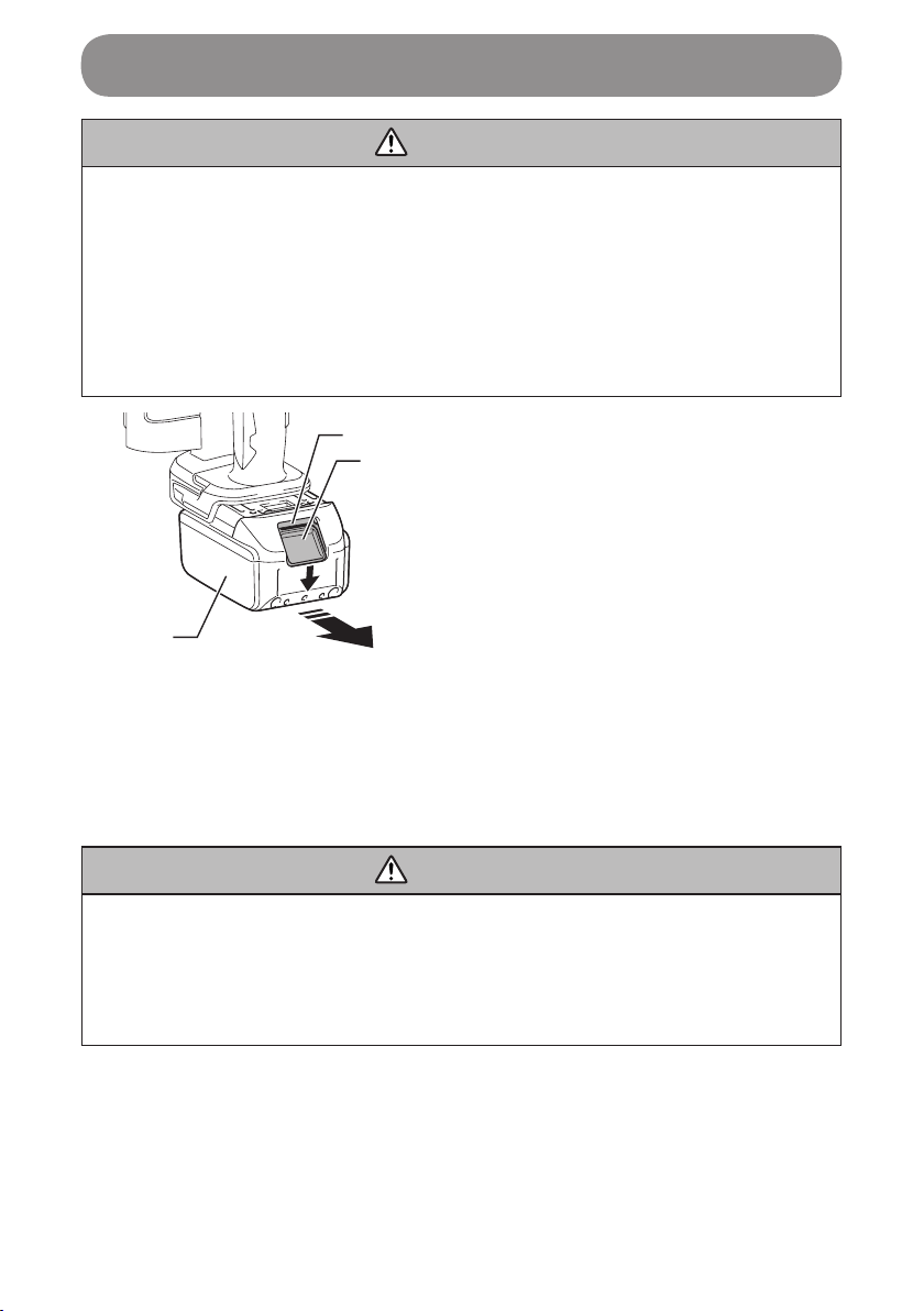
Installing or Removing Battery Cartridge
CAUTION
• Always be sure that the tool is switched off and the battery cartridge is
removed before adjusting or checking function on the tool.
• Always switch off the tool before installing or removing of the battery
cartridge.
• Hold the tool and the battery cartridge rmly when installing or removing
battery cartridge. Failure to hold the tool and the battery cartridge rmly
may cause them to slip off your hands and result in damage to the tool
and battery cartridge and a personal injury.
3
2
1
1. Red-colored section
2. Button
3. Battery cartridge
To remove the battery cartridge, slide it from the tool while sliding the button
on the front of the cartridge.
To install the battery cartridge, align the tongue on the battery cartridge with
the groove in the housing and slip it into place. Insert it all the way until it locks
in place with a little click. If you can see the red indicator on the upper side of
the button, it is not locked completely.
CAUTION
• Always install the battery cartridge fully until the red indicator cannot be
seen. If not, it may accidentally fall out of the tool, causing injury to you
or someone around you.
•Do not install the battery cartridge forcibly. If the cartridge does not slide
in easily, it is not being inserted correctly.
25
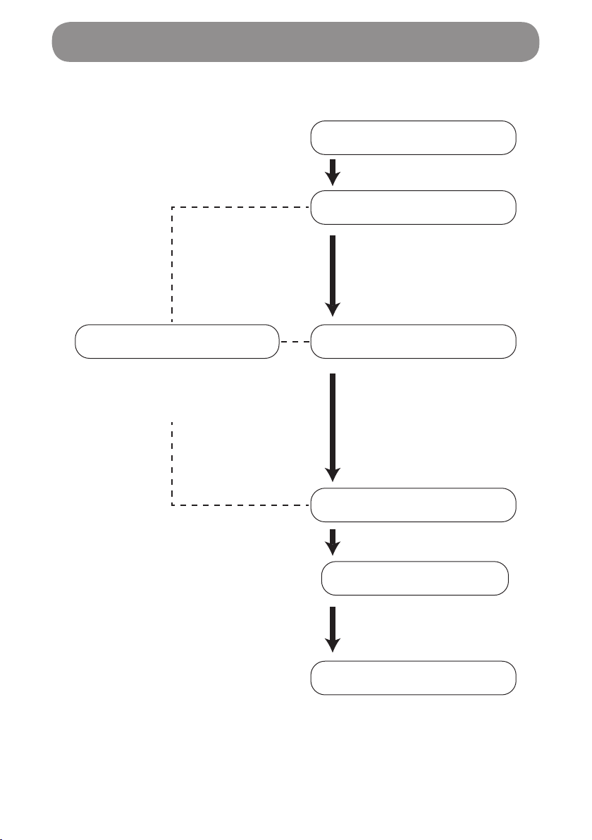
Operation ow
See below for the basic use of the scanner.
Startup
Scan mode selection
Scene selectionSetting
Scan
Marking
End
Make settings for the light,
laser, speaker, brightness,
etc. (See page 36.)
Select a mode from:
• Single Detection
• Multi Detection
Select a scene from:
• Dry Concrete
• Wet Concrete
• Partition
• Radar View
Mark the locations of
detected buried objects.
See page 26.
(See page 27.)
(See page 28.)
See page 30.
(See page 34.)
See page 35.
Using the Wall Scanner
26
Using the Wall Scanner
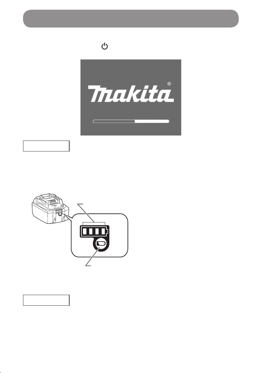
Startup
1. Press the power button ( ).
2. A signaling sound beeps, and the startup screen is shown in the display.
NOTE
• If the startup screen is not shown, the remaining battery capacity may be
low. Charge the battery.
In the case of a battery equipped with a battery indicator lamp, see the
illustration below to know the remaining battery capacity using the battery
indicator lamp.
1. Battery indicator lamp
2. Check button
2
1
3. The scan mode selection screen is shown.
NOTE
• If you see the battery change mark shown in the top right corner of the
display, check the remaining battery capacity, and if the battery capacity is
low, shut down the scanner and charge the battery.
27
Using the Wall Scanner
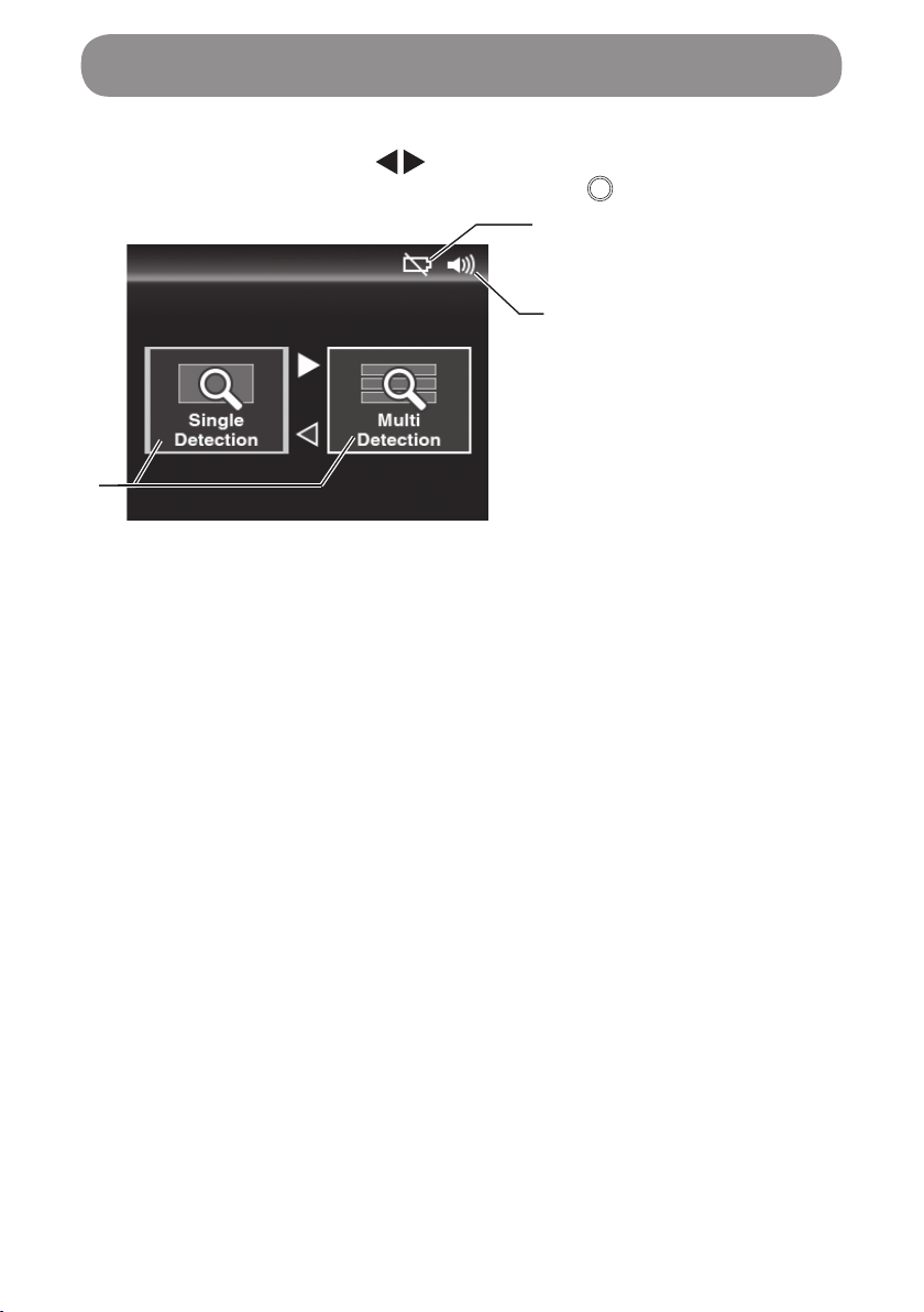
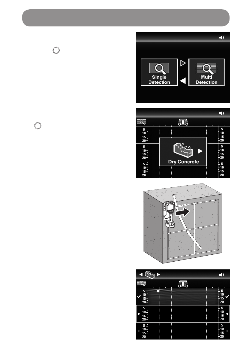
Selecting a scan mode
Use the right and left buttons ( ) to select either the “Single Detection” or
“Multi Detection” mode, and press the apply button ( ).
1. Battery change mark
2. Signaling sound on/off
3. Scan mode
3
1
2
1. “Single Detection” mode
This mode gives you the basic functionality. Move the scanner side to side
to detect any buried objects after applying the scanner's sensor surface
to the surface from which to detect any buried objects. Scan results are
shown in the scanner's display so that you can see the location and depth
data of the buried object.
When there is a buried object under the sensor, a burial detection mark
blinks or a beep sounds to let you know of it.
2. “Multi Detection” mode
This mode performs three lines of buried object scan continuously. The
scan results for the three lines are shown in the scanner's display. This
mode is useful to scan for buried objects which are not necessarily
straight, such as in-concrete power distribution resin tubes.
(See “Searching for wiring resin pipes in concrete” in page 41.)
28
Using the Wall Scanner
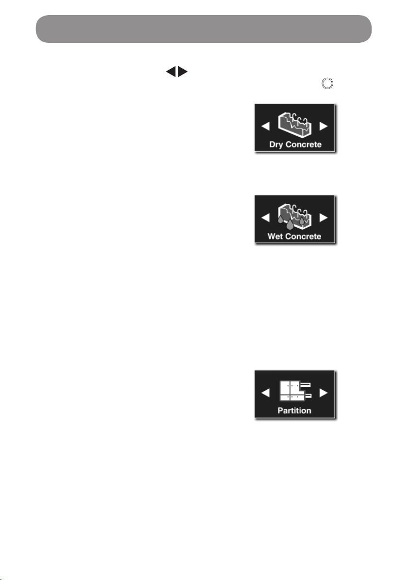
Selecting a scene
Use the right and left buttons ( ) to select either “Dry Concrete,” “Wet
Concrete,” “Partition” or “Radar View,” and press the apply button ( ).
1. Dry Concrete
(Maximum detection depth: 18 cm
(7 1/16"))
This scene is suitable to scan for
objects in dry concrete.
2. Wet Concrete
(Maximum detection depth: 10 cm
(3 15/16"))
This scene is suitable to scan for
objects in wet concrete.
Concrete needs several months to
be completely dried since placed,
and the concrete less than one year
after the placement is referred to as
wet concrete.
Select this scene in the case of
wet concrete, but to make it double
sure, it is recommended that “Dry
Concrete” be also used.
3. Partition
(Maximum detection depth: 8 cm
(3 1/8"))
This scene is suitable to scan for
objects behind a wooden or gypsum
board. With no display of burial
detection marks, scan results are
shown in waveforms only. (*)
(*) Some buried objects may not be detected up to the maximum detection
depth depending on their size, shape and material, as well as the material,
condition and internal structure of the wall to be scanned.

29
Using the Wall Scanner
4. Radar View
This scene is suitable to scan for
compound objects (multiple types of
objects) such as voids and iron bars
in a block or brick.
With no display of burial detection
marks, scan results are shown in
waveforms only.
(See “Searching for iron bars in a
block fence” in page 48.)(*)
(*) Some buried objects may not be detected up to the maximum detection
depth depending on their size, shape and material, as well as the material,
condition and internal structure of the wall to be scanned.
30
Using the Wall Scanner
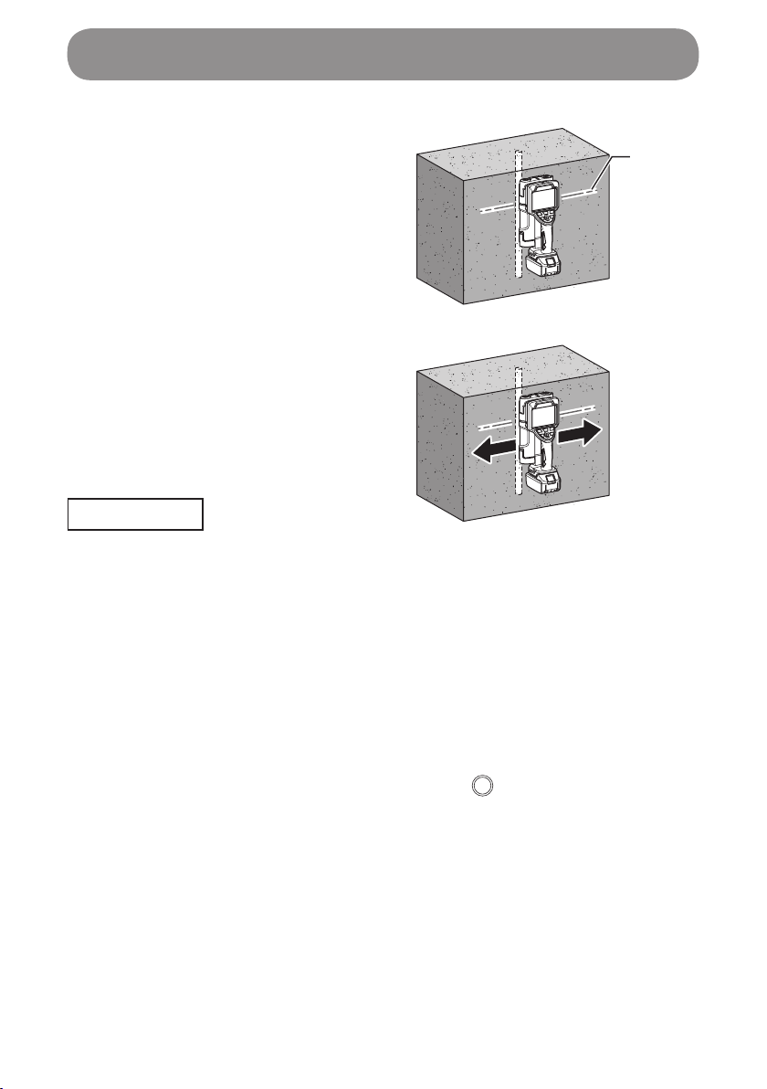
Scanning
1. Align the guide laser (the sensor's
right and left edge lines) with your
intended scan position, and apply
the scanner to the surface to be
scanned (concrete surface, etc.).
1. Guide laser (the sensor's right and left edge lines)
2. Move the scanner slowly side to side.
NOTE
• During operation, be careful not to allow the wheels to be away from the
surface being scanned.
• Move the scanner slowly. If moved too fast, an error message is shown,
during which a scan is unavailable.
• After detection, do not release the scanner from the surface being scanned
until marking is completed. If released, scan operation is discontinued.
• During a scan, if the scanner remains at rest for 10 seconds or more, scan
operation is discontinued.
• When a scan is started from the right in front of a buried object, scan
results may not be shown properly. If scan results do not come out as
estimated, change the starting position of scan a little.
• To try scanning again, press the apply button ( ) to clear the display of
scan results.
1
31
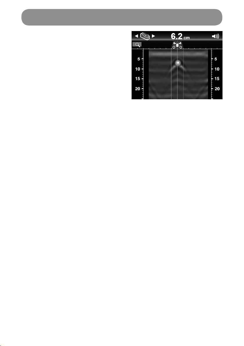
3. Radar scan results are shown on the
display.
Using the Wall Scanner

32
Scan result display
Single Detection
1. Sensor operation status
2. Scene
3. Sensor's center line
4. Depth scale marks
5. Scan operation area
6. Sensor's left edge line
(Represents the
scanner's left edge)
7. Burial detection mark
(In the sensor area)
[Blinks in red in a yellow
●]
8. Sensor area
9. Sensor's right edge line
(Represents the
scanner's right edge)
10. Burial detection mark
(Outside the sensor area)
[A yellow ●]
11. Operation guide arrow
12. Signaling sound on/off
13. Battery change mark
14. Depth to the buried object
1
2
4
5
6
9
3
13
12
11
14
8
10
7
15. Area not yet scanned
16. Area already scanned
16
15
Multi Detection
1. Line 1 (scan results)
2. Line 2 (scan results)
3. Line 3 (scan results)
1
2
3
Using the Wall Scanner
33
Waveforms
Waveforms are shown when buried
objects (iron bars, etc.) in concrete are
scanned.
Burial detection marks are shown at
points corresponding to the locations of
iron bars, etc. (*)
A signaling sound beeps when any burial
detection mark is there within the sensor
area.
(*)
Burial detection marks may not be
shown depending on the buried
object and the condition or internal
structure of the wall to be scanned.
In that case, estimate the correct
location from the waveform in the
image.
WARNING
Before drilling, sawing or routing into a wall, protect yourself against
hazards by using other information sources. As the measuring results can
be inuenced through ambient conditions or the wall material, there may
be a hazard even though the indicator does not indicate an object in the
sensor range (no audio signal or beep and burial detection marks).
Using the Wall Scanner
34
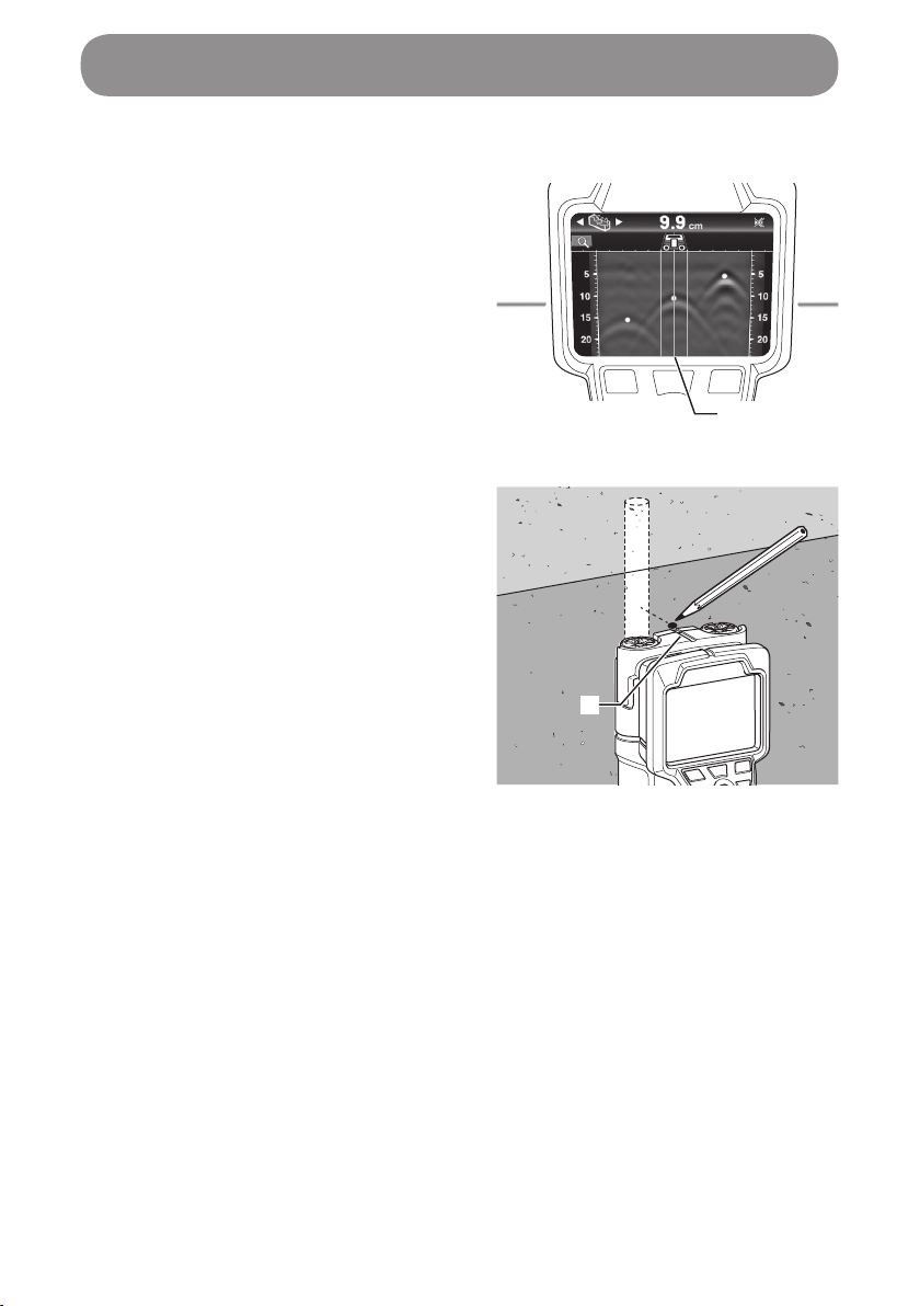
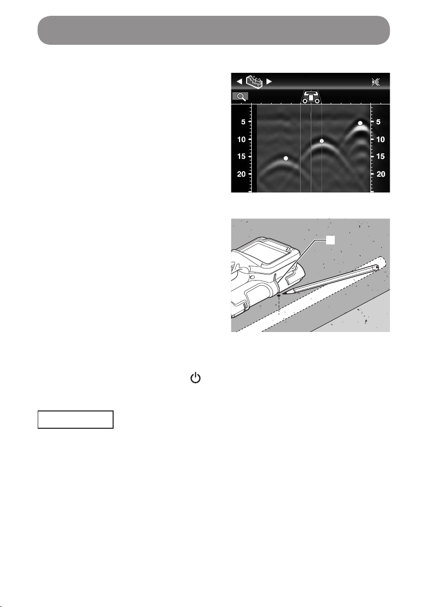
Marking the locations of buried objects
Marking with the use of the sensor's center line
1. Move the scanner to where the burial
detection mark on the screen is
aligned with the sensor's center line.
1. Sensor's center line
2. Make a marking at the recess at the
center of the scanner's upper edge.
The mark represents the center of
the buried object.
2. Recess
1
2
Using the Wall Scanner
35
Using the Wall Scanner
Marking with the use of the sensor's right (left) edge line
1. Move the scanner to where the
center of the iron bar detection mark
is aligned with the sensor's right
edge line.
* The sensor's right and left edge lines
on the screen represent the scanner's
both right and left edge lines.
2. Make a marking at the recess on the
scanner's right edge.
The mark represents the center of
the buried object.
1. Recess
Shutdown
Press and hold the power button ( ).
The end screen is shown, and after a few seconds, the power is turned off.
NOTE
• Do not remove the battery until the end screen goes out.
1
36
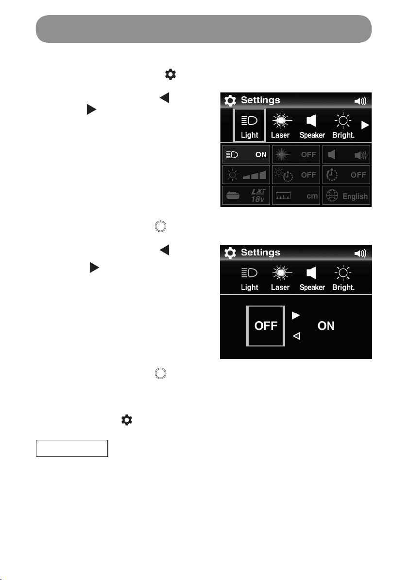
Making setting changes
1. Press the settings button ( ).
The settings screen is shown.
2. Press the left button ( ) or right
button ( ) to move the selection to
the settings item to which you want
to make changes.
3. Press the apply button ( ).
The setting options for the item that you have selected are shown.
4. Press the left button () or right
button () to select your desired
setting option.
The setting option that you selected
is set.
5. Press the apply button ( ).
The screen reverts to the settings screen.
To exit the settings screen to go back to the previous screen, press the
settings button ( ).
NOTE
• Setting changes are not reflected if the battery is removed when the
settings screen is displayed.
Do not remove the battery until the end screen goes out by pressing the
power button.
Settings
37
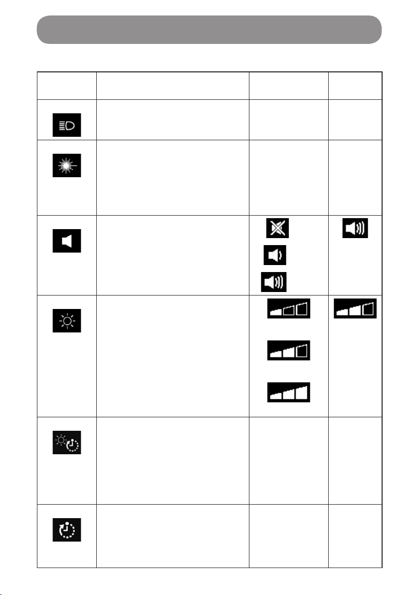
List of settings
Setting
icon Description Setting option Factory
default
Light Selects “ON” or “OFF” for the
light to see scan surfaces in dark
places.
ON
OFF
ON
Laser Selects “ON” or “OFF” for the
laser to see the "sensor's right
and left edge lines" provided at
the sensor's right and left sides
on the sensor scan surface. (See
page 51.)
ON
OFF
ON
Speaker Adjusts the volume of the
signaling sound emitted when an
operation button is operated or
when there is an object detected
in the scanner's sensor area.
(Off)
(Low)
(High)
(High)
Bright. Adjusts the brightness of the
display backlight.
(Low)
(Middle)
(High)
(Middle)
Sleep Sets the period of time elapsed
before the display backlight,
guide laser and light are turned
off when the scanner is switched
on and no operation takes place.
OFF(*1)
10 sec.
20 sec.
30 sec.
60 sec.
120 sec.
240 sec.
240 sec.
Off Timer Sets the period of time to
elapse for the scanner to be
automatically turned off when no
operation is performed while the
power is switched on.
OFF(*2)
1 min.
3 min.
5 min.
10 min.
5 min.
Settings
38
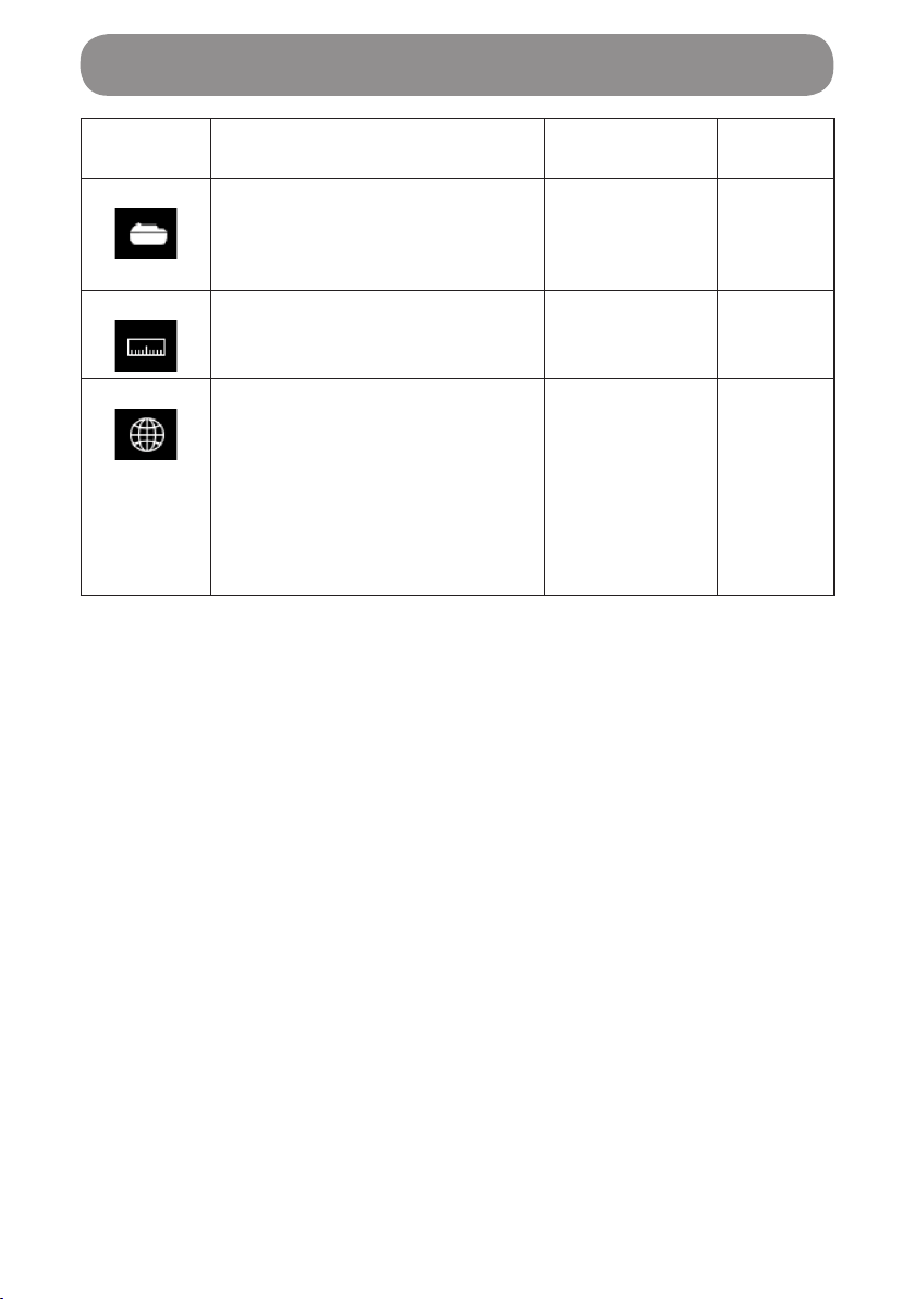
Setting
icon Description Setting option Factory
default
Battery Sets the voltage of the battery
used so that the need of battery
replacement is reported at an
appropriate timing.
14.4 V
18 V
18 V
Unit Selects the unit of measure for
the depth of buried objects.
cm
inch Decimal
inch Fractional
cm
Lang. Selects the language used in the
display.
English
Deutsch
Français
Italiano
Español
Nederlands
Português
Русский
English
*1: Always turned on when “OFF” is selected.
*2: Not switched off automatically when “OFF” is selected.
Settings

39
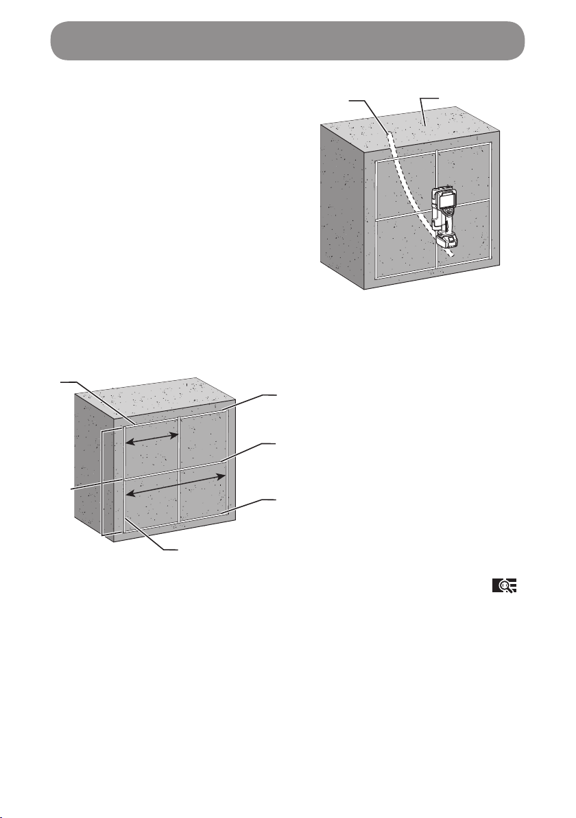
Searching for iron bars in concrete
• Scan mode:Single Detection
• Scene:Dry Concrete
1. Iron bar
2. Concrete
1. Turn on the scanner.
If the scanner has already been switched on, press the mode button ( ).
2. Select the scan mode of “Single
Detection” and press the apply
button ( ).
3. Select the scene of “Dry Concrete”
and press the apply button ( ).
NOTE
• To start scan operation, wait for the
operation guide arrow to be shown.
1
2
Operation

40
4. Align the guide laser (the sensor's right and left edge lines) with your
intended line to scan, and apply the scanner to the concrete surface.
5. Move the scanner slowly side to
side.
6. Scan results are shown on the
display.
7. Make markings at the detected iron bar locations. (See page 34.)
Operation
41
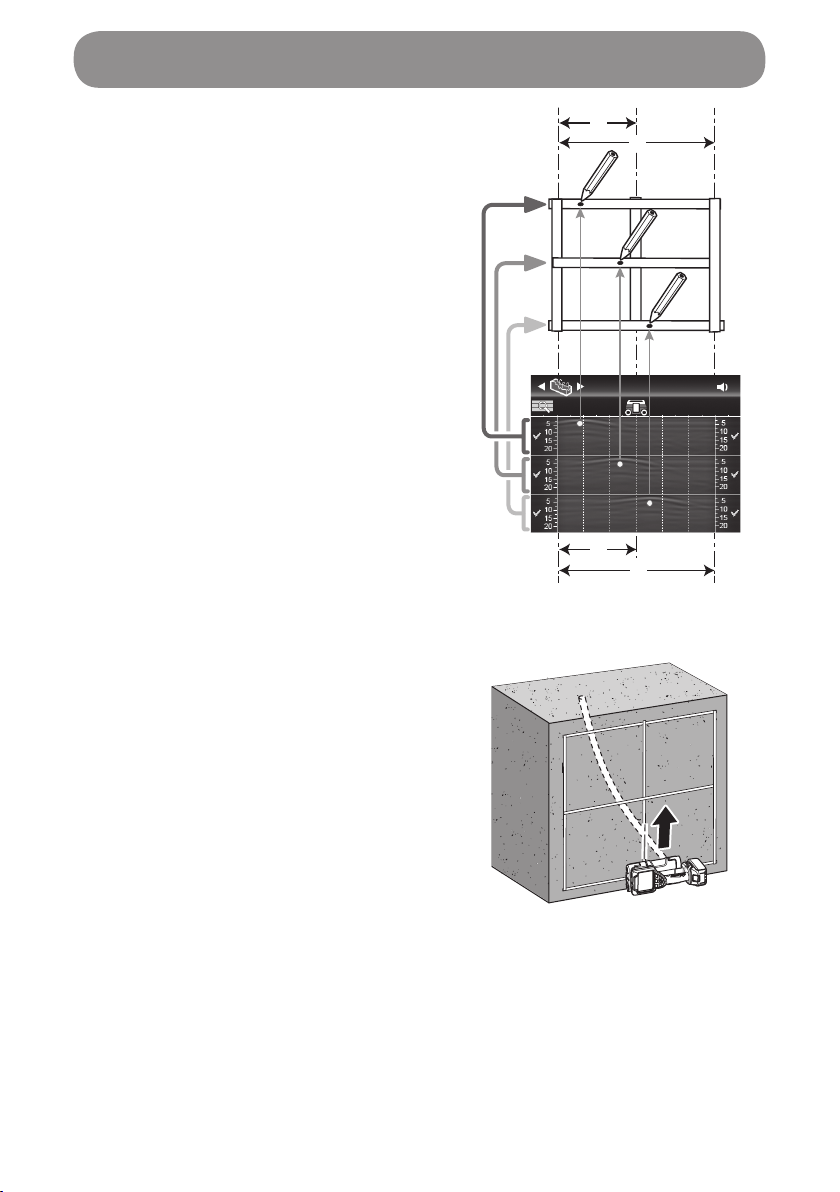
Searching for wiring resin pipes in concrete
• Scan mode: Multi Detection (*)
• Scene: Dry Concrete
(*) For wiring resin pipes, which are
often meandering unlike iron bars, it
is recommended the Multi Detection
mode which can scan three lines be
used.
1. Resin pipe
2. Concrete
1. Place masking tape to the concrete surface to show scan lines in a square
shape of 60 cm (23 5/8").
1. Masking tape
2. Three lines to be scanned
3. Upper line
4. Middle line
5. Lower line
6. Operation start line
A: 30 cm (11 13/16")
B: 60 cm (23 5/8")
1
6
B
A
3
4
5
2
2. Turn on the scanner.
If the scanner has already been switched on, press the mode button ( ).
12
Operation
42
3. Select the scan mode of “Multi
Detection” and press the apply
button ( ).
4. Select the scan mode of “Dry
Concrete” and press the apply button
().
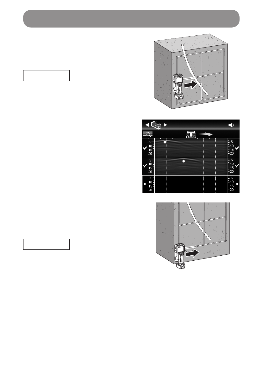
5. Align the guide laser (the sensor's
right and left edge lines) with the
upper masking tape line, and slowly
move the scanner on the line.
6. Scan results are shown on the
display. The scan results of the
“upper line” are shown in line 1 if the
scanner is released from the
concrete surface.
*If the apply button is pressed, the
scan of line 1 is reverted so that you
can start over a scan again.
Operation
43
Operation
7. Align the guide laser (the sensor's
right and left edge lines) with the
middle masking tape line, and slowly
move the scanner on the line.
NOTE
• Start scanning on the vertical
masking tape line so that the starting
position of scan can be aligned with
that of the upper line.
8. Scan results are shown on the
display. The scan results of the
“middle line” are shown in line 2 if the
scanner is released from the
concrete surface.
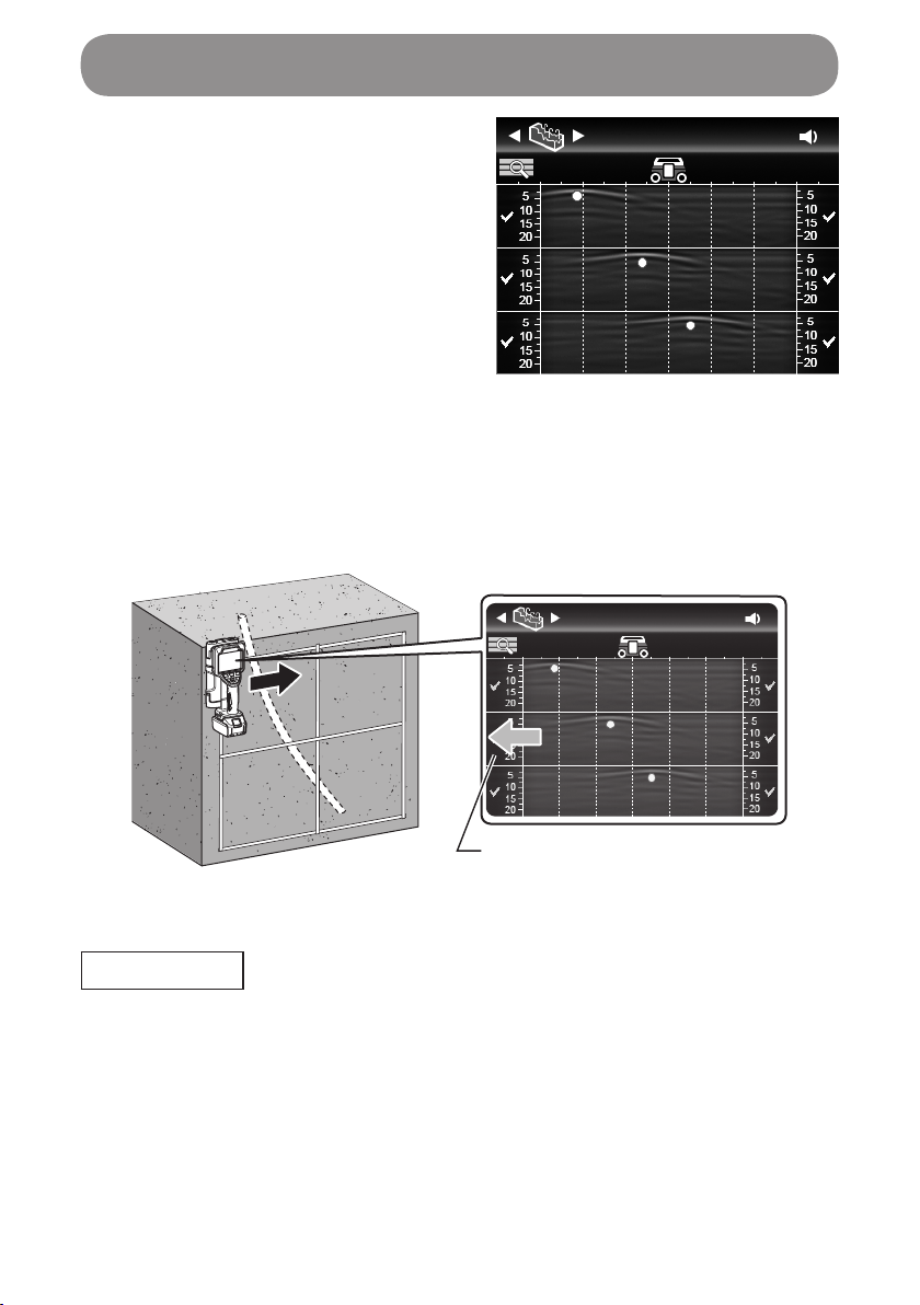
9. Align the guide laser (the sensor's
right and left edge lines) with the
lower masking tape line, and slowly
move the scanner on the line.
NOTE
• Start scanning on the vertical
masking tape line so that the starting
position of scan can be aligned with
that of the upper line.
44
Operation
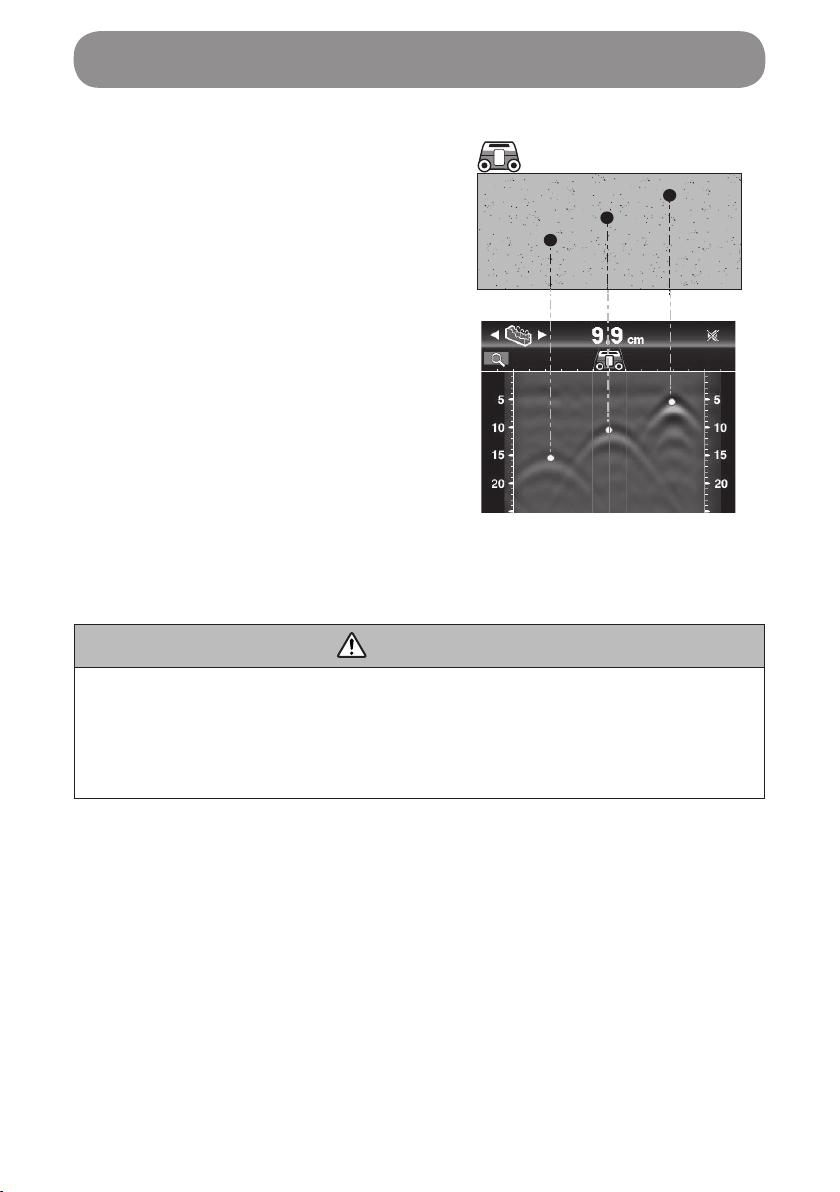
10. Scan results are shown on the
display. The scan results of the
“lower line” are shown in line 3 if the
scanner is released from the
concrete surface.
• Resin pipes, which in many cases
are not straight but are meandering,
give often their scan results as marks
located at differing positions and
depths depending on each line.
11. You can recheck scan results and the locations of buried objects if the
scanner is moved again from the position at which scan operation was
started.
• The screen (three lines) is scrolled in step with the movement of the
scanner.
1
1. The scan result screen is scrolled in
the direction of the arrow if the scan-
ner is moved as shown at left.
NOTE
• When you check scan results, apply the scanner to the same place as the
starting position of the executed scan. If the starting position is misaligned,
the correct position cannot be checked.
45
Operation
12. Make markings at the detected resin
pipe locations.
A: 30 cm (11 13/16")
B: 60 cm (23 5/8")
*It helps you identify the position of
the buried object more easily if you
scan also in the vertical direction with
the scanner oriented perpendicularly.
A
B
A
B

46
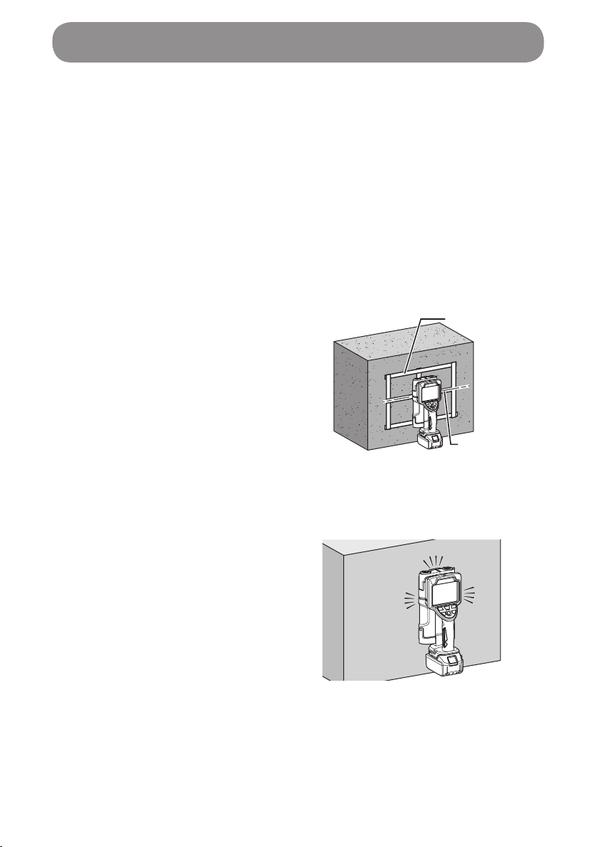
Searching for a pillar behind a gypsum board
• Scan mode:Single Detection
• Scene:Partition
1. Pillar
2. Gypsum board
1. Turn on the scanner.
If the scanner has already been switched on, press the mode button ( ).
2. Select the scan mode of “Single
Detection” and press the apply
button ( ).
3. Select the scan mode of “Partition”
and press the apply button ( ).
4. Align the guide laser (the sensor's right and left edge lines) with your
intended scan position, and apply the scanner to the gypsum board.
1
2
Operation
47
5. Move the scanner slowly side to side
on the partition's surface.
6. Scan results are shown on the display.
• Light gauge steel and wooden pillars behind gypsum board each appear
in waveforms as shown below. Estimate the locations of objects through
the characteristics and positions of the waveforms.
1. Light gauge steel
2. Wooden pillar
3. Characteristically shown <Light
gauge steel> graphics
4. Characteristically shown
<wooden pillar> graphics
7. Make markings at the detected pillar locations.
NOTE
• Detection may be instable when the scanner has just been started up.
To stably detect buried objects, wait for a while before you start scan
operation. Conrm scan results after several times of scan.
• Depending on the detection environment or the material of objects behind
gypsum board, the waveforms may be difcult to see. In addition to scan
results, see other information such as architectural drawings.
3
1
4
2
Operation
48
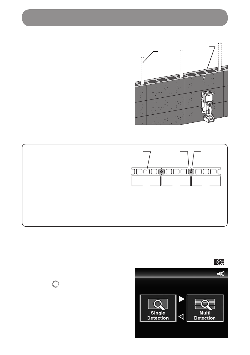
Searching for iron bars in a block fence
• Scan mode:Single Detection
• Scene:Radar View
1. Iron bar
2. Block fence
Block fences
Block fences generally have a
structure as shown at right.
Iron bars are placed between blocks,
and mortar is lled around each iron
bar.
1. Void
2. Mortar
3. Iron bar
4. Block
1
4 4 4
32
In this example, use the scene of “Radar View” to be able to detect both iron
bars and block voids.
1. Turn on the scanner.
If the scanner has already been switched on, press the mode button ( ).
2. Select the scan mode of “Single
Detection” and press the apply
button ( ).
12
Operation

49
3.
Select the scan mode of “Radar View”
and press the apply button ( ).
4. Move the scanner slowly side to side
on the block fence's surface.
Operation

50
5. Scan results are shown on the
display.
Buried iron bars and voids each appear
in waveforms as shown at right.
Estimate the locations of iron bars
through the characteristics and
positions of the waveforms.
Iron bar:
Waveforms appear in deeper
positions from the scan surface.
Block void:
Waveforms appear in shallower
positions from the scan surface.
1. Iron bar
2. Block void
Characteristically shown iron
bar graphics
Characteristically shown block
void graphics
12
Operation
51
To scan better
Before scan operation
• Remove dirt, dust or iron powder, if any, on the surface to be scanned.
• Scans cannot be done correctly if the surface to be scanned is wet. Make
sure the surface is dry.
• If the surface to be scanned has large projections, they may interfere with
the scanner's scan operation.
To scan more accurately
• If masking tape or such is used on
the scanning path, it serves as a
scanning aid, for example, by giving
you a guide mark to help you move
the scanner more accurately or
giving a guide mark when you make
markings for the estimated locations
of buried objects.
• The illumination of the guide laser
helps you scan correctly by giving
you a guide mark to move the
scanner straight.
1. Masking tape
2. Guide laser
Operation in dark places
Turn on the light when you scan in dark
places.
1
2
Operation

52
Locations of buried objects
The top of a parabolic form waveform represents the surface of the buried
object.
When the scene is set to “Dry Concrete” or “Wet Concrete,” burial detection
marks appear all in the same size irrespective of the width of each buried
object.
3
1
2
A
1. Surface being scanned
2. Upper surface of an iron bar
3. Black band
A: 9.2 cm (3 5/8")
Burial detection marks may appear in
misaligned positions due to the effects of
concrete honeycombs or other
irregularities in concrete.
In that case, estimate the correct location
from the waveform in the image.
In the image as shown in the right
example, point (a) is the correct location.
When a yellow marker does not appear
as well, the estimation may be possible
from the image.
1. Burial detection mark
(a)
1
Operation

53
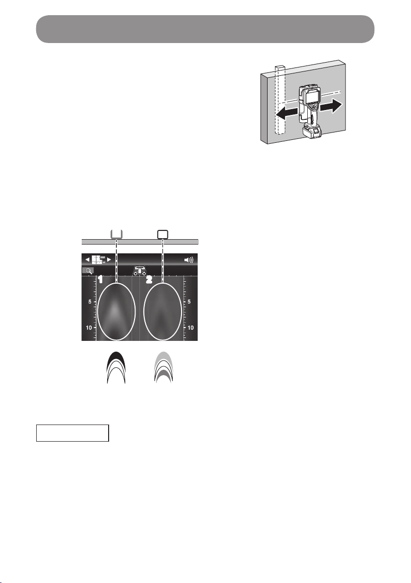
When adjacently buried objects are detected
When buried objects are adjacent to one another, they may not be shown as
independently individual single objects.
Detected as independent
two pieces
Detected as one piece
NOTE
• In the case of the selection of an excavation or boring place, allow the
scan starting position to have a good distance from the detected place.
Scan direction
The detection accuracy is the highest
when the buried object and the scanner
are positioned in parallel.
Operation
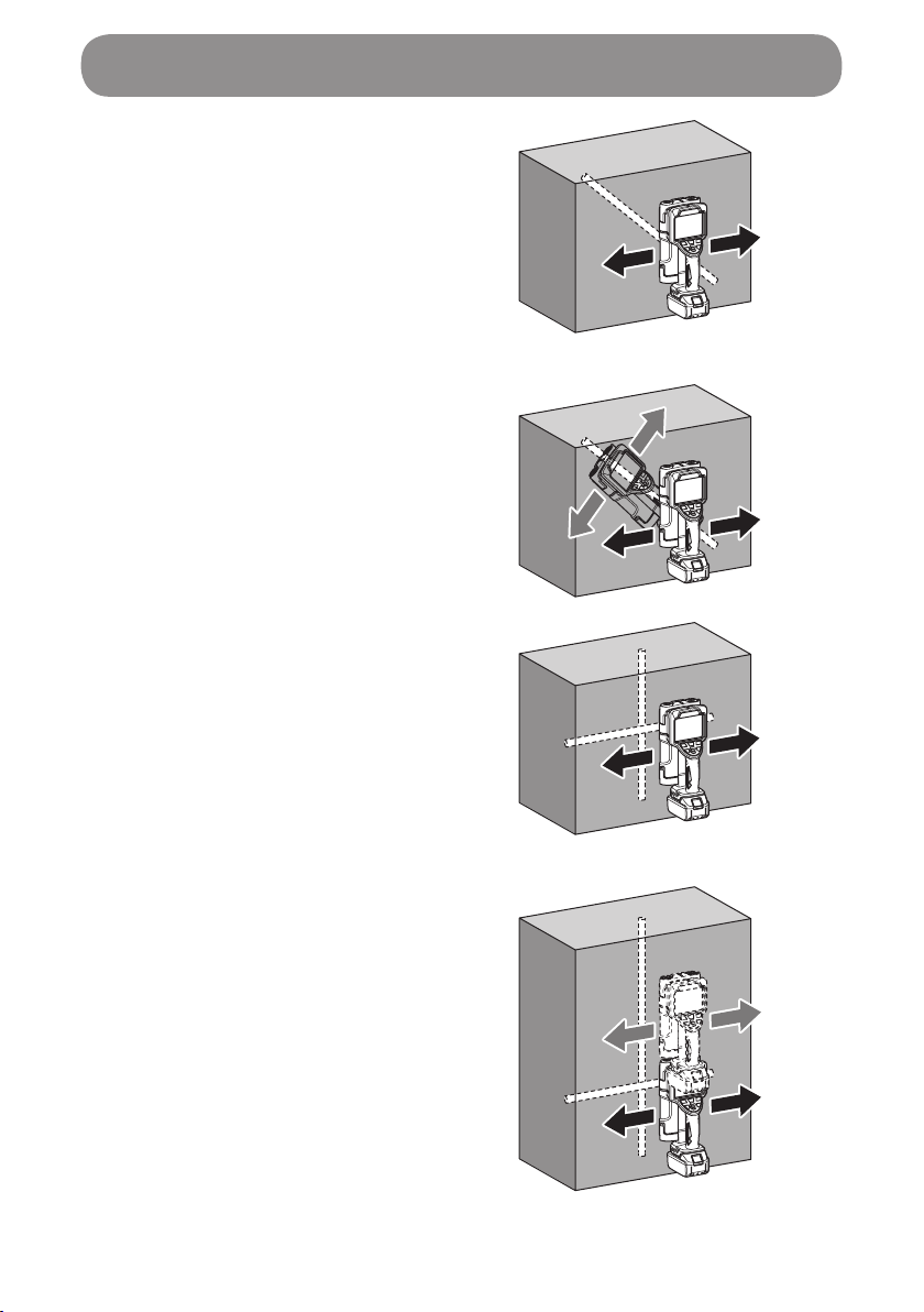
54
The correct detection may be prevented
when the buried object and the scanner
are not positioned in parallel.
When how iron bars are placed in
concrete is unknown, scan in more than
one direction.
The correct detection may be prevented
when the buried object is right in front of
the scanner and in parallel to the scan
direction.
In that case, scan at more than one
position.
Operation
55
Protective functions for the scanner and the battery
When the scanner is being used, if any of the following protection functions is
triggered, an error screen shown at right is displayed. This is caused by the
protection function and is not a sign of malfunction.
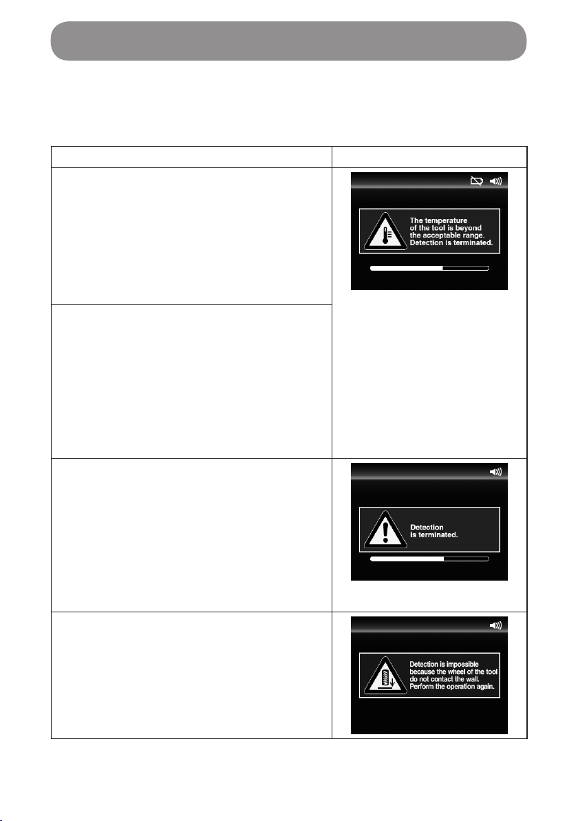
Protection function Error display
• Temperature error (high/low)
When the scanner is hot (cold), during
which the correct scan is prevented, the
message shown at right appears and
the scanner is forced to turn off.
• Turn on the power under a temperature
environment within the scanner's
specication.
• Temperature error (sudden change)
When the scanner has a sudden
temperature change, during which the
correct scan is prevented, the message
shown at right appears and the scanner
is forced to turn off.
• Turn on the power under a temperature
environment within the scanner's
specication.
• Internal error
When the scanner detects an internal
processing error, during which the
correct scan is prevented, the message
shown at right appears and the scanner
is forced to turn off.
*If this screen is displayed, contact a
dealer or a Makita sales ofce to make
a repair request.
• Wheel slip protection function
When there is an error in wheel turn
detection, during which the correct
scan is prevented, the message shown
at right appears and prompts you to
correct your operation.
Protection System
56
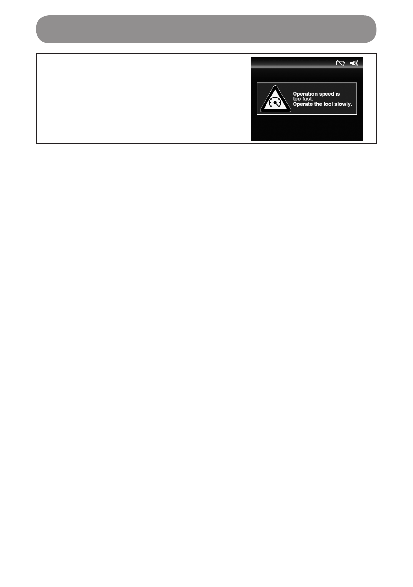
• Speed excess protection function
When your operation is too fast, during
which the correct scan is prevented, the
message shown at right appears and
prompts you to correct your operation.
Protection System

57
WARNING
Always be sure that the tool is switched off and the battery cartridge is
removed before attempting to perform inspection or maintenance.
Care of the product
• Wipe the product clean using a dry cloth or a cloth with a diluted neutral
detergent.
NOTE
• Never wash the product with water.
The entrance of water inside the product may cause a malfunction.
• Never use gasoline, benzine, thinner, alcohol or the like. Discoloration,
deformation or cracks may result.
To maintain product SAFETY and RELIABILITY, repairs, any other
maintenance or adjustment should be performed by Makita Authorized or
Factory Service Centers, always using Makita replacement parts.
Maintenance

ENGLISH
EU Declaration of Conformity
We as the manufacturers: Makita Europe N.V., Business
address: Jan-Baptist Vinkstraat 2, 3070 Kortenberg,
BELGIUM. Authorize Hiroshi Tsujimura for the compilation
of the technical le and declare under our sole responsibility
that the product(s); Designation: Rechargeable Wall
Scanner. Designation of Type(s): DWD181. Fullls all
the relevant provisions of 2014/53/EU and also fullls all
the relevant provisions of the following EC/EU Directives:
2011/65/EU.
EU type-examination for 2014/53/EU; Notied Body:
TÜV SÜD Product Service GmbH Zertizierstellen,
Ridlerstraße 65 80339 MÜNCHEN, Germany, Identication
number: 0123, Certicate number: TPS-RED500184 i01,
and are manufactured in accordance with the following
Harmonised Standards: EN 61010-1:2010, EN 62311:2008,
EN 60825-1:2014, EN 301 489-1: V2.1.1 (2017-02), EN 301
489-33: V2.2.1 (2019-04), EN 302 066 V2.1.1 (2017-01), EN
IEC63000:2018, EN 50581:2012.
Place of declaration: Kortenberg, Belgium. Responsible
person: Hiroshi Tsujimura, Director - Makita Europe N.V.
(date and signature on the last page)
FRANÇAIS
Déclaration de conformité UE
Nous, Makita Europe N.V., en tant que fabricant, ayant
pour adresse commerciale : Jan-Baptist Vinkstraat 2, 3070
Kortenberg, Belgique, autorisons Hiroshi Tsujimura à
compiler le chier technique et déclarons sous notre entière
responsabilité que le produit ; désignation : Scanner mural
sans l, désignation de type : DWD181, satisfait toutes les
dispositions pertinentes de 2014/53/EU et satisfait également
toutes les dispositions pertinentes des directives CE/UE
suivantes : 2011/65/EU.
Examen de type UE pour 2014/53/EU ; organisme notié :
TÜV SÜD Product Service GmbH Zertizierstellen,
Ridlerstraße 65 80339 MÜNCHEN, Allemagne, Numéro
d’identication : 0123, numéro de certicat : TPS-RED500184
i01 et est fabriqué conformément aux normes standardisées
suivantes : EN 61010-1:2010, EN 62311:2008, EN 60825-
1:2014, EN 301 489-1: V2.1.1 (2017-02), EN 301 489-
33: V2.2.1 (2019-04), EN 302 066 V2.1.1 (2017-01), EN
IEC63000:2018, EN 50581:2012.
Lieu de la déclaration : Kortenberg, Belgique. Responsable :
Hiroshi Tsujimura, Directeur – Makita Europe N.V. (date et
signature sur la dernière page)
DEUTSCH
EU-Konformitätserklärung
Wir als die Hersteller: Makita Europe N.V.,
Geschäftsadresse: Jan-Baptist Vinkstraat 2, 3070
Kortenberg, Belgien. beauftragen Hiroshi Tsujimura mit
der Zusammenstellung der technischen Dokumentation
und erklären unter unserer alleinigen Verantwortung, dass
das (die) Produkt(e); Bezeichnung: Akku-Ortungsgerät.
Bezeichnung des (der) Typs (Typen): DWD181. alle
relevanten Vorschriften von 2014/53/EU erfüllt und außerdem
alle relevanten Vorschriften der folgenden EG/EU-Richtlinien
erfüllt: 2011/65/EU.
EU-Baumusterprüfung für 2014/53/EU; Benannte Stelle:
TÜV SÜD Product Service GmbH Zertizierstellen,
Ridlerstraße 65 80339 MÜNCHEN, Deutschland,
Identizierungsnummer: 0123, Bescheinigungsnummern:
TPS-RED500184 i01 und im Einklang mit den folgenden
harmonisierten Normen steht: EN 61010-1:2010, EN
62311:2008, EN 60825-1:2014, EN 301 489-1: V2.1.1 (2017-
02), EN 301 489-33: V2.2.1 (2019-04), EN 302 066 V2.1.1
(2017-01), EN IEC63000:2018, EN 50581:2012.
Ort der Erklärung: Kortenberg, Belgien. Verantwortliche
Person: Hiroshi Tsujimura, Direktor – Makita Europe N.V.
(Datum und Unterschrift auf der letzten Seite)
ITALIANO
Dichiarazione di conformità UE
In qualità di fabbricante, Makita Europe N.V., con indirizzo
aziendale Jan-Baptist Vinkstraat 2, 3070 Kortenberg,
Belgio, autorizza Hiroshi Tsujimura alla compilazione
della documentazione tecnica e dichiara, sotto la propria
ed esclusiva responsabilità, che il prodotto o i prodotti
con designazione Rilevatore a parete ricaricabile, e con
designazione del tipo o dei tipi DWD181, sono conformi a
tutte le disposizioni rilevanti della normativa 2014/53/EU, e
che sono, inoltre, conformi a tutte le disposizioni rilevanti delle
Direttive CE/UE seguenti: 2011/65/EU.
Esame di tipo UE per la normativa 2014/53/EU;
Ente noticato: TÜV SÜD Product Service GmbH
Zertizierstellen, Ridlerstraße 65 80339 MÜNCHEN,
Germania, Numero di identicazione: 0123, Numeri dei
certicati: TPS-RED500184 i01 e che sono fabbricati in
conformità agli Standard Armonizzati seguenti, EN 61010-
1:2010, EN 62311:2008, EN 60825-1:2014, EN 301 489-1:
V2.1.1 (2017-02), EN 301 489-33: V2.2.1 (2019-04), EN 302
066 V2.1.1 (2017-01), EN IEC63000:2018, EN 50581:2012.
Sede della dichiarazione: Kortenberg, Belgio. Persona
responsabile: Hiroshi Tsujimura, Direttore – Makita Europe
N.V. (data e rma sull’ultima pagina)

NEDERLANDS
EU-verklaring van conformiteit
Wij als de fabrikant: Makita Europe N.V., vestigingsadres:
Jan-Baptist Vinkstraat 2, 3070 Kortenberg, België,
volmachtigen Hiroshi Tsujimura tot samenstelling van het
technisch dossier en verklaren als enige verantwoordelijke
dat het product(en), omschrijving: Oplaadbare
muurscanner; typenummer: DWD181; voldoet aan alle
relevante voorschriften van richtlijn 2014/53/EU en tevens
voldoet aan alle relevante voorschriften van de volgende EG/
EU-richtlijnen: 2011/65/EU.
EU type-onderzoek voor 2014/53/EU; Verwittigde instantie:
TÜV SÜD Product Service GmbH Zertizierstellen,
Ridlerstraße 65 80339 MÜNCHEN, Duitsland,
Identicatienummer: 0123, Certicatienummer: TPS-
RED500184 i01 en is vervaardigd in overeenstemming met
de volgende geharmoniseerde normen: EN 61010-1:2010,
EN 62311:2008, EN 60825-1:2014, EN 301 489-1: V2.1.1
(2017-02), EN 301 489-33: V2.2.1 (2019-04), EN 302 066
V2.1.1 (2017-01), EN IEC63000:2018, EN 50581:2012.
Plaats van verklaring: Kortenberg, België. Verantwoordelijke
persoon: Hiroshi Tsujimura, Directeur – Makita Europe
N.V. (datum en handtekening op de laatste pagina).
ESPAÑOL
Declaración UE de conformidad
Nosotros como los fabricantes: Makita Europe N.V.,
Dirección comercial: Jan-Baptist Vinkstraat 2, 3070
Kortenberg, Bélgica. Autorizamos a Hiroshi Tsujimura para
la compilación del archivo técnico y declaramos ante nuestra
sola responsabilidad que el(los) producto(s); Designación:
Escáner de Pared Recargable. Designación de tipo(s):
DWD181. Cumple todas las provisiones pertinentes de
2014/53/EU y también cumple con todas las provisiones
pertinentes de las Directivas CE/UE siguientes: 2011/65/EU.
Examen tipo UE para 2014/53/EU; Organismo facultativo:
TÜV SÜD Product Service GmbH Zertizierstellen,
Ridlerstraße 65 80339 MÜNCHEN, Alemania, Número
de identicación: 0123, Números de certicado: TPS-
RED500184 i01 y está fabricado de acuerdo con los
estándares unicados siguientes: EN 61010-1:2010, EN
62311:2008, EN 60825-1:2014, EN 301 489-1: V2.1.1 (2017-
02), EN 301 489-33: V2.2.1 (2019-04), EN 302 066 V2.1.1
(2017-01), EN IEC63000:2018, EN 50581:2012.
Lugar de la declaración: Kortenberg, Bélgica. Persona
responsable: Hiroshi Tsujimura, Director – Makita Europe
N.V. (fecha y rma en la última página)
PORTUGUÊS
Declaração de conformidade da UE
A empresa, na qualidade de fabricante: Makita Europe
N.V., Endereço comercial: Jan-Baptist Vinkstraat 2, 3070
Kortenberg, Bélgica. Autorizamos Hiroshi Tsujimura a
realizar a compilação do cheiro técnico e declaramos,
ao abrigo da nossa própria responsabilidade, que o(s)
produto(s); Designação: Detetor de Materiais a Bateria.
Designação de tipo(s): DWD181. Cumpre todas as
indicações relevantes da 2014/53/EU cumprindo ainda todas
as indicações relevantes das seguintes diretivas da CE/UE:
2011/65/EU.
Tipo de exame da UE para 2014/53/EU; Organismo
noticado: TÜV SÜD Product Service GmbH
Zertizierstellen, Ridlerstraße 65 80339 MÜNCHEN,
Alemanha, Número de identicação: 0123, Números de
certicado: TPS-RED500184 i01 e são fabricados de acordo
com as seguintes Normas Harmonizadas: EN 61010-1:2010,
EN 62311:2008, EN 60825-1:2014, EN 301 489-1: V2.1.1
(2017-02), EN 301 489-33: V2.2.1 (2019-04), EN 302 066
V2.1.1 (2017-01), EN IEC63000:2018, EN 50581:2012.
Local da declaração: Kortenberg, Bélgica. Pessoa
responsável: Hiroshi Tsujimura, Diretor – Makita Europe
N.V. (data e assinatura na última página)
DANSK
EU konformitetserklæring
Vi som producenter: Makita Europe N.V.,
Forretningsadresse: Jan-Baptist Vinkstraat 2, 3070
Kortenberg, Belgien, autoriserer Hiroshi Tsujimura
til kompilationen af den tekniske l og erklærer, under
vores eneansvar, at produktet (produkterne), Betegnelse:
Genopladelig vægscanner. Betegnelse for type (typer):
DWD181, opfylder alle de relevante betingelser for 2014/53/
EU og desuden opfylder alle de relevante betingelser i de
følgende EF/EU-direktiver: 2011/65/EU.
EU type-eksamination for 2014/53/EU; Noticeret
organisation: TÜV SÜD Product Service GmbH
Zertizierstellen, Ridlerstraße 65 80339 MÜNCHEN,
Tyskland, Identikationsnummer: 0123, Certikatnumre:
TPS-RED500184 i01 og er fremstillet i overensstemmelse
med de følgende harmoniserede standarder: EN 61010-
1:2010, EN 62311:2008, EN 60825-1:2014, EN 301 489-1:
V2.1.1 (2017-02), EN 301 489-33: V2.2.1 (2019-04), EN 302
066 V2.1.1 (2017-01), EN IEC63000:2018, EN 50581:2012.
Sted for erklæring: Kortenberg, Belgien. Ansvarlig person:
Hiroshi Tsujimura, Direktør – Makita Europe N.V. (dato og
underskrift på den sidste side)

ΕΛΛΗΝΙΚΑ
Δήλωση Συμμόρφωσης ΕΕ
Εμείς ως οι κατασκευαστές: Makita Europe N.V., Διεύθυνση
επιχείρησης: Jan-Baptist Vinkstraat 2, 3070 Kortenberg,
Βέλγιο. Εξουσιοδοτούμε τον Hiroshi Tsujimura για
τη σύνταξη του τεχνικού αρχείου και δηλώνουμε, υπό
την αποκλειστική ευθύνη μας, ότι το(α) προϊόν(τα),
Χαρακτηρισμός: Επαναφορτιζόμενος ανιχνευτής τοίχου.
Χαρακτηρισμός τύπου(ων): DWD181. Ικανοποιεί όλες τις
σχετικές διατάξεις της Οδηγίας 2014/53/EU και επίσης
ικανοποιεί όλες τις σχετικές διατάξεις των ακόλουθων
Οδηγιών ΕΚ/ΕΕ: 2011/65/EU.
Εξέταση τύπου ΕΕ για 2014/53/EU, Κοινοποιημένος φορέας:
TÜV SÜD Product Service GmbH Zertizierstellen,
Ridlerstraße 65 80339 MÜNCHEN, Γερμανία,
Αναγνωριστικός αριθμός: 0123, Αριθμοί πιστοποιητικού: TPS-
RED500184 i01 και κατασκευάζεται σύμφωνα με τα ακόλουθα
εναρμονισμένα πρότυπα: EN 61010-1:2010, EN 62311:2008,
EN 60825-1:2014, EN 301 489-1: V2.1.1 (2017-02), EN 301
489-33: V2.2.1 (2019-04), EN 302 066 V2.1.1 (2017-01), EN
IEC63000:2018, EN 50581:2012.
Τόπος της δήλωσης: Kortenberg, Βέλγιο. Υπεύθυνος:
Hiroshi Tsujimura, Διευθυντής – Makita Europe N.V.
(ημερομηνία και υπογραφή στην τελευταία σελίδα)
TÜRKÇE
AB Uygunluk Beyanı
Üretici olarak biz, iş adresi Jan-Baptist Vinkstraat 2, 3070
Kortenberg, Belçika olan Makita Europe N.V.; Hiroshi
Tsujimura’yı teknik dosyanın hazırlanması için yetkilendiriyor
ve tek sorumlu olarak Ürün Adı: Şarjlı Duvar Tarayıcı Model
Adı: DWD181 olan ürünün/ürünlerin 2014/53/EU’nin ilgili
tüm hükümlerinin gerekliliklerini yerine getirdiğini, ve ayrıca
2011/65/EU AT/AB Direktierinin ilgili tüm hükümlerinin
gerekliliklerini yerine getirdiğini beyan ediyoruz.
2014/53/EU için AB tipi inceleme; Onaylanmış Kuruluş:
TÜV SÜD Product Service GmbH Zertizierstellen,
Ridlerstraße 65 80339 MÜNCHEN, Almanya, Tanımlama
numarası: 0123, Sertika numarası: TPS-RED500184 i01,
ve EN 61010-1:2010, EN 62311:2008, EN 60825-1:2014, EN
301 489-1: V2.1.1 (2017-02), EN 301 489-33: V2.2.1 (2019-
04), EN 302 066 V2.1.1 (2017-01), EN IEC63000:2018, EN
50581:2012 Eşdeğer Standartlarına uygun olarak üretildiğini
beyan ediyoruz.
Beyan yeri: Kortenberg, Belçika. Sorumlu kişi: Hiroshi
Tsujimura, Müdür – Makita Europe N.V. (tarih ve imza son
sayfada bulunmaktadır)
SVENSKA
EU-försäkran om överensstämmelse
I egenskap av tillverkare: Makita Europe N.V., med
företagsadress Jan-Baptist Vinkstraat 2, 3070
Kortenberg, Belgien, auktoriserar vi Hiroshi Tsujimura för
sammanställningen av den tekniska dokumentationen och
försäkrar under ansvar att produkten (eller produkterna) –
Beteckning: Uppladdningsbar regelsökare. Typbeteckning:
DWD181. – uppfyller alla relevanta bestämmelser i 2014/53/
EU och även uppfyller alla relevanta bestämmelser i följande
EG/EU-direktiv: 2011/65/EU.
EU-typkontroll för 2014/53/EU; Anmält organ: TÜV SÜD
Product Service GmbH Zertizierstellen, Ridlerstraße 65
80339 MÜNCHEN, Tyskland, Identieringsnummer: 0123,
Certikatnummer: TPS-RED500184 i01 samt är tillverkade i
enlighet med följande harmoniserade standarder: EN 61010-
1:2010, EN 62311:2008, EN 60825-1:2014, EN 301 489-1:
V2.1.1 (2017-02), EN 301 489-33: V2.2.1 (2019-04), EN 302
066 V2.1.1 (2017-01), EN IEC63000:2018, EN 50581:2012.
Plats för givande av försäkran: Kortenberg, Belgien.
Ansvarig person: Hiroshi Tsujimura, Direktör – Makita
Europe N.V. (datum och underskrift på sista sidan)
NORSK
EU-samsvarserklæring
Vi, som produsenter:
Makita Europe N.V., Forretningsadresse: Jan-Baptist
Vinkstraat 2, 3070 Kortenberg, Belgia
autoriserer Hiroshi Tsujimura til å kompilere den tekniske
len og erklærer under vårt eneansvar at produktet;
Betegnelse: Gjenoppladbar veggskanner
Modellbetegnelse: DWD181
oppfyller alle relevante bestemmelser i 2014/53/EU og at det
også oppfyller alle bestemmelser i følgende EF/EU-direktiver:
2011/65/EU.
EU-typetest for 2014/53/EU; varslet organ: TÜV SÜD
Product Service GmbH Zertizierstellen, Ridlerstraße
65 80339 MÜNCHEN, Tyskland, ID-nummer: 0123,
sertikatnumre: TPS-RED500184 i01 og er produsert i
samsvar med følgende harmoniserte standarder: EN 61010-
1:2010, EN 62311:2008, EN 60825-1:2014, EN 301 489-1:
V2.1.1 (2017-02), EN 301 489-33: V2.2.1 (2019-04), EN 302
066 V2.1.1 (2017-01), EN IEC63000:2018, EN 50581:2012.
Sted for erklæring: Kortenberg, Belgia.
Ansvarlig: Hiroshi Tsujimura, Direktør - Makita Europe N.V.
(dato og signatur på siste side)

SUOMI
EU-vaatimustenmukaisuusvakuutus
Vastuullinen valmistaja: Makita Europe N.V., yrityksen
osoite: Jan-Baptist Vinkstraat 2, 3070 Kortenberg, Belgia,
valtuuttaa Hiroshi Tsujimuran kokoamaan tekniset asiakirjat
ja vakuuttaa omalla vastuullaan, että tuote (tuotteet); Laitteen
nimi: Ladattava seinäskanneri. Laitteen tyyppi (tyypit):
DWD181, täyttää kaikki direktiivin 2014/53/EU olennaiset
vaatimukset sekä täyttää myös kaikki seuraavien EY-/EU-
direktiivien olennaiset vaatimukset: 2011/65/EU.
EU-tyyppitarkastus direktiivin 2014/53/EU mukaan; Ilmoitettu
laitos: TÜV SÜD Product Service GmbH Zertizierstellen,
Ridlerstraße 65 80339 MÜNCHEN, Saksa, Tunnistenumero:
0123, sertikaatin numero: TPS-RED500184 i01 ja on
valmistettu seuraavien yhdenmukaistettujen standardien
mukaisesti: EN 61010-1:2010, EN 62311:2008, EN 60825-
1:2014, EN 301 489-1: V2.1.1 (2017-02), EN 301 489-
33: V2.2.1 (2019-04), EN 302 066 V2.1.1 (2017-01), EN
IEC63000:2018, EN 50581:2012.
Ilmoituksen antopaikka: Kortenberg, Belgia. Vastuuhenkilö:
Hiroshi Tsujimura, johtaja – Makita Europe N.V.
(päivämäärä ja allekirjoitus viimeisellä sivulla)
LATVIEŠU
ES atbilstības deklarācija
Ražotājs Makita Europe N.V., juridiskā adrese: Jan-
Baptist Vinkstraat 2, 3070 Kortenberg, Beļģija, pilnvaro
savu pārstāvi Hiroshi Tsujimura sagatavot tehnisko
dokumentāciju un ar mūsu vienpersonisko atbildību paziņot,
ka izstrādājums(-i), nosaukums: Uzlādējams sienas
skeneris, veids(-i): DWD181, atbilst visiem attiecīgajiem
direktīvas 2014/53/EU noteikumiem, kā arī atbilst visiem
attiecīgajiem šādu EK/ES direktīvu noteikumiem: 2011/65/EU.
ES tipa pārbaude Direktīvai 2014/53/EU; pilnvarotā iestāde:
TÜV SÜD Product Service GmbH Zertizierstellen,
Ridlerstraße 65 80339 MÜNCHEN, Vācija, Identikācijas
numurs: 0123, sertikātu numuri: TPS-RED500184 i01 un ir
ražots(-i) saskaņā ar šādiem harmonizētajiem standartiem:
EN 61010-1:2010, EN 62311:2008, EN 60825-1:2014, EN
301 489-1: V2.1.1 (2017-02), EN 301 489-33: V2.2.1 (2019-
04), EN 302 066 V2.1.1 (2017-01), EN IEC63000:2018, EN
50581:2012.
Deklarācijas izdošanas vieta: Kortenberg, Beļģija. Atbildīgā
persona: Makita Europe N.V. direktors Hiroshi Tsujimura
(datumu un parakstu skatiet pēdējā lapā)
LIETUVIŲ KALBA
ES atitikties deklaracija
Mes, gamintojai Makita Europe N.V., įmonės adresas: Jan-
Baptist Vinkstraat 2, 3070 Kortenberg, Belgija, įgaliojame
Hiroshi Tsujimura parengti techninę bylą ir savo išskirtine
atsakomybe deklaruojame, kad gaminys (-iai); žymuo:
Įkraunamas sienų skeneris; tipo (-ų) žymuo: DWD181;
atitinka galiojančias 2014/53/EU nuostatas ir taip pat
atitinka visas aktualias nuostatas, išdėstytas šiose EB/ES
direktyvose: 2011/65/EU.
ES tipo tyrimas pagal 2014/53/EU. Paskelbtoji įstaiga:
TÜV SÜD Product Service GmbH Zertizierstellen,
Ridlerstraße 65 80339 MÜNCHEN, Vokietija, Identikacinis
numeris: 0123, sertikatų numeriai: TPS-RED500184 i01,
pagamintas (-i) pagal toliau nurodytus darniuosius standartus:
EN 61010-1:2010, EN 62311:2008, EN 60825-1:2014, EN
301 489-1: V2.1.1 (2017-02), EN 301 489-33: V2.2.1 (2019-
04), EN 302 066 V2.1.1 (2017-01), EN IEC63000:2018, EN
50581:2012.
Deklaravimo vieta: Kortenberg, Belgija. Atsakingasis asmuo:
Makita Europe N.V. direktorius Hiroshi Tsujimura (data ir
parašas pateikti paskutiniame puslapyje)
EESTI
EL vastavusdeklaratsioon
Meie kui tootjad: Makita Europe N.V., juriidiline aadress:
Jan-Baptist Vinkstraat 2, 3070 Kortenberg, Belgia,
volitame Hiroshi Tsujimura koostama tehnilist toimikut ja
kinnitame oma ainuvastutusel, et toode/tooted; nimetus:
Laetav seinaskanner; tüübi/tüüpide kood: DWD181; vastab/
vastavad direktiivi 2014/53/EU kõigile asjaomastele sätetele
ja vastab/vastavad ka järgmiste EÜ/EL direktiivide kõigile
asjaomastele sätetele: 2011/65/EU.
EL tüübihindamine standardile 2014/53/EU; teavitatud
asutus: TÜV SÜD Product Service GmbH Zertizierstellen,
Ridlerstraße 65 80339 MÜNCHEN, Saksamaa,
Identitseerimisnumber: 0123; sertikaadi numbrid: TPS-
RED500184 i01 ja on toodetud kooskõlas järgmiste
ühtlustatud standardite: EN 61010-1:2010, EN 62311:2008,
EN 60825-1:2014, EN 301 489-1: V2.1.1 (2017-02), EN 301
489-33: V2.2.1 (2019-04), EN 302 066 V2.1.1 (2017-01), EN
IEC63000:2018, EN 50581:2012.
Deklareerimiskoht: Kortenberg, Belgia. Vastutav isik:
Hiroshi Tsujimura, direktor − Makita Europe N.V. (kuupäev
ja allkiri viimasel leheküljel)

POLSKI
Deklaracja zgodności UE
My jako producent: Makita Europe N.V., adres rmy:
Jan-Baptist Vinkstraat 2, 3070 Kortenberg, Belgia.
Upoważniamy pana Hiroshi Tsujimura do opracowania
dokumentacji technicznej i wydania oświadczenia na naszą
wyłączną odpowiedzialność, że produkt(y); Opis: Detektor
Akumulatorowy. Oznaczenie typu (typów): DWD181.
Spełniają wszelkie stosowne postanowienia normy 2014/53/
EU i dodatkowo spełniają wszelkie stosowne postanowienia
poniższych Dyrektyw WE/UE: 2011/65/EU.
Badanie typu UE dla dyrektywy 2014/53/EU; Organ
notykowany TÜV SÜD Product Service GmbH
Zertizierstellen, Ridlerstraße 65 80339 MÜNCHEN,
Niemcy, Numer identykacyjny: 0123, Numery certykatów:
TPS-RED500184 i01 i są produkowane zgodnie z
następującymi zharmonizowanymi normami: EN 61010-
1:2010, EN 62311:2008, EN 60825-1:2014, EN 301 489-1:
V2.1.1 (2017-02), EN 301 489-33: V2.2.1 (2019-04), EN 302
066 V2.1.1 (2017-01), EN IEC63000:2018, EN 50581:2012.
Miejsce złożenia deklaracji: Kortenberg, Belgia. Osoba
odpowiedzialna: Hiroshi Tsujimura, Dyrektor Makita
Europe N.V. (data i podpis na ostatniej stronie)
MAGYAR
EU megfelelőségi nyilatkozat
Felelős gyártóként, a Makita Europe N.V., székhely címe:
Jan-Baptist Vinkstraat 2, 3070 Kortenberg, Belgium,
feljogosítjuk Hiroshi Tsujimurát a műszaki dokumentáció
összeállítására, és saját kizárólagos felelősségünkre
kijelentjük, hogy a termék(ek); rendeltetése: Újratölthető fali
szkenner; típusmegnevezése: DWD181; megfelel a 2014/53/
EU irányelv minden vonatkozó rendelkezésének, továbbá
megfelel az alábbi EK/EU irányelvek minden vonatkozó
rendelkezésének: 2011/65/EU.
EU-típusvizsgálat a 2014/53/EU irányelvnek megfelelően;
Illetékes szervezet: TÜV SÜD Product Service GmbH
Zertizierstellen, Ridlerstraße 65 80339 MÜNCHEN,
Németország, Azonosítási szám: 0123, Képesítési
igazolás száma: TPS-RED500184 i01 és gyártása az
alábbi harmonizált szabványoknak: EN 61010-1:2010, EN
62311:2008, EN 60825-1:2014, EN 301 489-1: V2.1.1 (2017-
02), EN 301 489-33: V2.2.1 (2019-04), EN 302 066 V2.1.1
(2017-01), EN IEC63000:2018, EN 50581:2012.
A nyilatkozattétel helye: Kortenberg, Belgium. Felelős
személy: Hiroshi Tsujimura, igazgató – Makita Europe N.V.
(dátum és aláírás az utolsó lapon)
SLOVENSKY
Vyhlásenie o zhode v rámci EÚ
Naša spoločnosť, ako výrobca: Makita Europe N.V., remná
adresa: Jan-Baptist Vinkstraat 2, 3070 Kortenberg,
Belgicko. Týmto oprávňujeme Hiroshi Tsujimura na
zostavenie technického súboru a vyhlasujeme na našu
výhradnú zodpovednosť, že výrobok(ky); Označenie:
Nabíjateľný stenový skener. Označenie typu(ov): DWD181.
Spĺňa všetky príslušné ustanovenia 2014/53/EU a taktiež
spĺňa všetky príslušné ustanovenia nasledujúcich smerníc
ES/EÚ: 2011/65/EU.
Skúška typu EÚ pre 2014/53/EU; Oboznámený orgán:
TÜV SÜD Product Service GmbH Zertizierstellen,
Ridlerstraße 65 80339 MÜNCHEN, Nemecko, Identikačné
číslo: 0123, číslo certikátu: TPS-RED500184 i01 a je
vyrobená v súlade s nasledujúcimi harmonizovanými
normami: EN 61010-1:2010, EN 62311:2008, EN 60825-
1:2014, EN 301 489-1: V2.1.1 (2017-02), EN 301 489-
33: V2.2.1 (2019-04), EN 302 066 V2.1.1 (2017-01), EN
IEC63000:2018, EN 50581:2012.
Miesto vyhlásenia: Kortenberg, Belgicko. Zodpovedná
osoba: Hiroshi Tsujimura, riaditeľ – Makita Europe N.V.
(dátum a podpis sú uvedené na poslednej strane)
ČESKY
EU prohlášení o shodě
My, jako výrobci: Makita Europe N.V., Adresa rmy: Jan-
Baptist Vinkstraat 2, 3070 Kortenberg, Belgie. Pověřujeme
Hiroshi Tsujimura sestavením technické dokumentace a
prohlašujeme na naši vlastní odpovědnost, že produkt(y);
Označení: Akumulátorový hloubkový detektor. Typové
označení: DWD181. Splňuje veškerá příslušná ustanovení
směrnice 2014/53/EU a také splňuje všechna související
ustanovení následujících směrnic ES/EU: 2011/65/EU.
Přezkoušení typu EU pro 2014/53/EU; Notikovaný orgán:
TÜV SÜD Product Service GmbH Zertizierstellen,
Ridlerstraße 65 80339 MÜNCHEN, Německo, Identikační
číslo: 0123, Čísla certikátu: TPS-RED500184 i01 a je
vyroben v souladu s následujícími harmonizovanými
normami: EN 61010-1:2010, EN 62311:2008, EN 60825-
1:2014, EN 301 489-1: V2.1.1 (2017-02), EN 301 489-
33: V2.2.1 (2019-04), EN 302 066 V2.1.1 (2017-01), EN
IEC63000:2018, EN 50581:2012.
Místo prohlášení: Kortenberg, Belgie. Odpovědná osoba:
Hiroshi Tsujimura, ředitel – Makita Europe N.V. (datum a
podpis na poslední straně)

SLOVENSKO
EU-izjava o skladnosti
Mi, podjetje: Makita Europe N.V., poslovni naslov: Jan-
Baptist Vinkstraat 2, 3070 Kortenberg, Belgija. ko
proizvajalec pooblaščamo g. Hiroshi Tsujimura za sestavo
tehnične datoteke in na lastno odgovornost izjavljamo, da
je izdelek; oznaka: Akumulatorski detektor materialov
Oznaka vrst(e): DWD181. V skladu z vsemi zadevnimi določili
2014/53/EU ter ustreza zahtevam vseh bistvenih določil
naslednjih Direktiv ES/EU: 2011/65/EU.
Pregled vrste EU za 2014/53/EU; priglašeni organ: TÜV SÜD
Product Service GmbH Zertizierstellen, Ridlerstraße 65
80339 MÜNCHEN, Nemčija, Identikacijska številka: 0123,
številke certikatov: TPS-RED500184 i01 in je izdelan v
skladu z naslednjimi harmoniziranimi standardi: EN 61010-
1:2010, EN 62311:2008, EN 60825-1:2014, EN 301 489-1:
V2.1.1 (2017-02), EN 301 489-33: V2.2.1 (2019-04), EN 302
066 V2.1.1 (2017-01), EN IEC63000:2018, EN 50581:2012.
Kraj izjave: Kortenberg, Belgija. Odgovorna oseba: Hiroshi
Tsujimura, direktor – Makita Europe N.V. (datum in podpis
na zadnji strani)
SHQIP
Deklarata e konformitetit e BE-së
Ne, si kompania prodhuese: Makita Europe N.V., me adresë
biznesi: Jan-Baptist Vinkstraat 2, 3070 Kortenberg,
Belgjikë, autorizojmë Hiroshi Tsujimura për përpilimin
e skedarit teknik dhe deklarojmë se është përgjegjësia
jonë e vetme se produkti(et); Përkuzimi: Skaner muri i
rikarikueshëm. Përcaktimi i llojit(eve): DWD181, përmbush
të gjitha dispozitat përkatëse të 2014/53/EU dhe gjithashtu
përmbush dispozitat përkatëse të direktivave vijuese të KE/
BE: 2011/65/EU.
Ekzaminimi i llojit të BE-së për 2014/53/EU; Organi i njoftuar:
TÜV SÜD Product Service GmbH Zertizierstellen,
Ridlerstraße 65 80339 MÜNCHEN, Gjermani, Numri i
identikimit: 0123, Numrat e certikatës: TPS-RED500184 i01
dhe prodhohet në pajtim me standardet e harmonizuara në
vijim: EN 61010-1:2010, EN 62311:2008, EN 60825-1:2014,
EN 301 489-1: V2.1.1 (2017-02), EN 301 489-33: V2.2.1
(2019-04), EN 302 066 V2.1.1 (2017-01), EN IEC63000:2018,
EN 50581:2012.
Vendi i deklaratës: Kortenberg, Belgjikë. Personi përgjegjës:
Hiroshi Tsujimura, drejtor – Makita Europe N.V. (data dhe
rma në faqen e fundit)
БЪЛГАРСКИ
EС декларация за съответствие
В качеството си на производител ние: Makita Europe N.V.,
с адрес на управление: Jan-Baptist Vinkstraat 2, 3070
Kortenberg, Белгия, упълномощаваме Hiroshi Tsujimura
да състави техническото досие и да декларира от наше
име, че продукта(ите): Наименование: Акумулаторен
стенен скенер. Модел: DWD181 Отговаря(т) на
съответните разпоредби на 2014/53/EU и освен това
отговаря(т) на съответните разпоредби на следните ЕО/
EС директиви: 2011/65/EU.
EС изследване на типа за 2014/53/EU; Нотифициран
орган: TÜV SÜD Product Service GmbH Zertizierstellen,
Ridlerstraße 65 80339 MÜNCHEN, Германия,
Идентификационен номер: 0123, Номер на сертификат:
TPS-RED500184 i01. Продуктите се произвеждат в
съответствие със следните хармонизирани стандарти:
EN 61010-1:2010, EN 62311:2008, EN 60825-1:2014, EN
301 489-1: V2.1.1 (2017-02), EN 301 489-33: V2.2.1 (2019-
04), EN 302 066 V2.1.1 (2017-01), EN IEC63000:2018, EN
50581:2012.
Място на издаване на декларацията: Kortenberg, Белгия
Оторизирано лице: Hiroshi Tsujimura, Директор – Makita
Europe N.V. (дата и подпис на последната страница)
HRVATSKI
EU izjava o sukladnosti
Mi kao proizvođači: Makita Europe N.V., sa sjedištem u Jan-
Baptist Vinkstraat 2, 3070 Kortenberg, Belgija ovlašćujemo
Hiroshija Tsujimuru za sastavljanje tehničke datoteke i
izjavljujemo pod vlastitom isključivom odgovornošću da je
proizvod(i); Oznaka: Punjivi zidni skener. Oznaka vrste(a):
DWD181. Zadovoljava sve relevantne odredbe direktive
2014/53/EU i također zadovoljava sve relevantne odredbe
sljedećih direktiva EZ/EU: 2011/65/EU.
EU vrsta-ispitivanje za 2014/53/EU; Nadležno tijelo: TÜV SÜD
Product Service GmbH Zertizierstellen, Ridlerstraße
65 80339 MÜNCHEN, Njemačka, Identikacijski broj: 0123,
Brojevi certikata: TPS-RED500184 i01 te se proizvodi u
skladu sa sljedećim usklađenim normama: EN 61010-1:2010,
EN 62311:2008, EN 60825-1:2014, EN 301 489-1: V2.1.1
(2017-02), EN 301 489-33: V2.2.1 (2019-04), EN 302 066
V2.1.1 (2017-01), EN IEC63000:2018, EN 50581:2012.
Mjesto davanja izjave: Kortenberg, Belgija. Odgovorna
osoba: Hiroshi Tsujimura, direktor – Makita Europe N.V.
(datum i potpis na zadnjoj stranici)

МАКЕДОНСКИ
Изјава за сообразност на EУ
Ние, производителите: Makita Europe N.V., со деловна
адреса: Jan-Baptist Vinkstraat 2, 3070 Kortenberg,
Белгија. Го овластуваме Hiroshi Tsujimura за
составување на техничката датотека и изјавуваме
под наша лична одговорност дека производот(-ите);
Ознака: Ѕиден скенер на полнење. Ознака на тип(-
ови): DWD181. Ги исполнува сите релевантни одредби
на 2014/53/EU и исто така ги исполнува сите релевантни
одредби на следните директиви на ЕЗ/EУ: 2011/65/EU.
EУ испитување на типот за 2014/53/EU; Известен орган:
TÜV SÜD Product Service GmbH Zertizierstellen,
Ridlerstraße 65 80339 MÜNCHEN, Германија,
Идентификациски број: 0123, Броj на сертификат: TPS-
RED500184 i01 и се произведени во согласност со
следниве усогласени стандарди: EN 61010-1:2010, EN
62311:2008, EN 60825-1:2014, EN 301 489-1: V2.1.1 (2017-
02), EN 301 489-33: V2.2.1 (2019-04), EN 302 066 V2.1.1
(2017-01), EN IEC63000:2018, EN 50581:2012.
Место на давање на изјавата: Kortenberg, Белгија.
Одговорно лице: Hiroshi Tsujimura, Директор – Makita
Europe N.V. (датум и потпис на последната страница)
ROMÂNĂ
Declaraţie de conformitate UE
Noi, Makita Europe N.V., cu sediul social în: Jan-Baptist
Vinkstraat 2, 3070 Kortenberg, Belgia, în calitate de
producători, îl împuternicim pe Hiroshi Tsujimura pentru
redactarea şierului tehnic şi declarăm pe proprie răspundere
că produsul (produsele): Denumire: Scanner perete
reîncărcabil. Denumirea modelului (modelelor): DWD181.
respectă toate prevederile relevante ale directivei 2014/53/
EU şi, de asemenea, respectă prevederile relevante ale
următoarelor directive CE/UE: 2011/65/EU.
Examinarea tip UE pentru 2014/53/EU; Organism noticat:
TÜV SÜD Product Service GmbH Zertizierstellen,
Ridlerstraße 65 80339 MÜNCHEN, Germania, Număr de
identicare: 0123, Numerele certicatului: TPS-RED500184
i01. Este fabricat în conformitate cu următoarele standarde
armonizate: EN 61010-1:2010, EN 62311:2008, EN 60825-
1:2014, EN 301 489-1: V2.1.1 (2017-02), EN 301 489-
33: V2.2.1 (2019-04), EN 302 066 V2.1.1 (2017-01), EN
IEC63000:2018, EN 50581:2012.
Locul declaraţiei: Kortenberg, Belgia. Persoana
responsabilă: Hiroshi Tsujimura, Director – Makita Europe
N.V. (data şi semnătura pe ultima pagină)
СРПСКИ
EУ декларација о усаглашености
Ми као произвођач: Makita Europe N.V., пословна адреса:
Jan-Baptist Vinkstraat 2, 3070 Kortenberg, Белгија,
овлашћујемо Hiroshi Tsujimura да састави техничку
документацију и под нашом искључивом одговорношћу
изјави да следећи производ: ознака: Пуњиви зидни
скенер, ознака типа: DWD181 испуњава све одговарајуће
одредбе директиве 2014/53/EU и да испуњава све
одговарајуће одредбе следећих директива EЗ/EУ: 2011/65/
EU.
Преглед EУ типа за 2014/53/EU; Обавештена страна:
TÜV SÜD Product Service GmbH Zertizierstellen,
Ridlerstraße 65 80339 MÜNCHEN, Немачка,
Идентификациони број: 0123, Бројеви сертификата: TPS-
RED500184 i01, да је произведен у складу са следећим
хармонизованим стандардима: EN 61010-1:2010, EN
62311:2008, EN 60825-1:2014, EN 301 489-1: V2.1.1 (2017-
02), EN 301 489-33: V2.2.1 (2019-04), EN 302 066 V2.1.1
(2017-01), EN IEC63000:2018, EN 50581:2012.
Место изјаве: Kortenberg, Белгија. Одговорна особа:
Hiroshi Tsujimura, директор – Makita Europe N.V. (датум
и потпис се налазе на последњој страници)
РУССКИЙ
Сертификат соответствия ЕС
Производители: Makita Europe N.V., Рабочий адрес:
Jan-Baptist Vinkstraat 2, 3070 Kortenberg, Бельгия.
уполномочиваем Hiroshi Tsujimura для составления
файла технических данных и заявляем со всей нашей
ответственностью, что изделие(я); Наименование:
Аккумуляторный строительный детектор. Обозначение
типа(ов): DWD181. Удовлетворяет всем соответствующим
положениям 2014/53/EU, а также удовлетворяет всем
соответствующим положениям следующих Директив ЕС/
ЕС: 2011/65/EU.
Экспертиза вида ЕС для 2014/53/EU; Уполномоченный
орган: TÜV SÜD Product Service GmbH Zertizierstellen,
Ridlerstraße 65 80339 MÜNCHEN, Германия,
Идентификационный номер: 0123, Сертификационные
номера: TPS-RED500184 i01 и производится согласно
следующим Гармонизированным Стандартам: EN 61010-
1:2010, EN 62311:2008, EN 60825-1:2014, EN 301 489-1:
V2.1.1 (2017-02), EN 301 489-33: V2.2.1 (2019-04), EN 302
066 V2.1.1 (2017-01), EN IEC63000:2018, EN 50581:2012.
Место декларирования: Kortenberg, Бельгия.
Ответственное лицо: Hiroshi Tsujimura, Директор
– Makita Europe N.V. (дата и подпись на последней
странице)

ҚАЗАҚША
ЕО-ның сәйкестік жөніндегі
Өндіруші ретінде әрекет ететін:
Makita Europe N.V., Жұмыс мекенжайы: Jan-Baptist
Vinkstraat 2, 3070 Kortenberg, Бельгия
Hiroshi Tsujimura мырзаға техникалық файлды құрастыру
өкілдігін беріп, айрықша жауапкершілікпен келесі
өнім(-дер):
Атауы: Қайта зарядталатын қабырға сканері
Түрінің(түрлерінің) коды: DWD181.
2014/53/EU стандартының барлық тиісті талаптарына,
сонымен қатар 2011/65/EU ЕҚ/ЕО директиваларының
барлық тиісті талаптарына сәйкес келеді деп мәлімдейді.
2014/53/EU талаптарына сәйкес ЕО түріндегі тексеріс;
Хабар берілетін орган: TÜV SÜD Product Service GmbH
Zertizierstellen, Ridlerstraße 65 80339 MÜNCHEN,
Германия, идентификатор: 0123, сертификат №: TPS-
RED500184 i01, EN 61010-1:2010, EN 62311:2008, EN
60825-1:2014, EN 301 489-1: V2.1.1 (2017-02), EN 301
489-33: V2.2.1 (2019-04), EN 302 066 V2.1.1 (2017-01), EN
IEC63000:2018, EN 50581:2012 келісілген стандарттарына
сәйкес жасап шығарылды деп мәлімдейді.
Мәлімдеме орны: Kortenberg, Бельгия.
Жауапты тұлға: Hiroshi Tsujimura, Директор – Makita
Europe N.V. (дата мен қол соңғы бетке қойылған)
УКРАЇНСЬКА
Декларація про відповідність стандартам ЄС
Ми, як виробник: Makita Europe N.V., адреса компанії:
Jan-Baptist Vinkstraat 2, 3070 Kortenberg, Бельгія.
Надаємо Hiroshi Tsujimura, уповноваження складати
технічну документацію і з повною відповідальністю
заявляємо щодо виробу(ів) таке; Найменування:
Акумуляторний будівельний детектор. Визначення
типу(ів): DWD181. Відповідають усім відповідним
положенням 2014/53/EU а також відповідають усім
відповідним положенням таких директив ЄС/ЄС: 2011/65/
EU.
Сертифікація на відповідність вимогам ЄС згідно 2014/53/
EU; Нотифікований орган: TÜV SÜD Product Service
GmbH Zertizierstellen, Ridlerstraße 65 80339 MÜNCHEN,
Німеччина, Ідентифікаційний номер: 0123, номера
сертифікатів: TPS-RED500184 i01 та виготовлені згідно
таких єдиних стандартів: EN 61010-1:2010, EN 62311:2008,
EN 60825-1:2014, EN 301 489-1: V2.1.1 (2017-02), EN 301
489-33: V2.2.1 (2019-04), EN 302 066 V2.1.1 (2017-01), EN
IEC63000:2018, EN 50581:2012.
Місце декларування: Kortenberg, Бельгія. Відповідальна
особа: Hiroshi Tsujimura, директор – Makita Europe N.V.
(дата і підпис на останній сторінці)
简体中文
EU一致性声明
我们作为制造商:Makita Europe N.V.,营业地址:Jan-
Baptist Vinkstraat 2, 3070 Kortenberg, 比利时。授权
Hiroshi Tsujimura编译技术文件,并在我们单独负责之下
声明产品;名称:墙体探测仪。类型名称:DWD181。满足
2014/53/EU的所有相关条款,并且也满足以下EC/EU指示的所
有相关条款:2011/65/EU。
2014/53/EU的EU类型检查;通知主体:TÜV SÜD Product
Service GmbH Zertizierstellen, Ridlerstraße 65 80339
MÜNCHEN,德国,标识号:0123,
证书号:TPS-RED500184 i01,并根据以下协调标准制造:EN
61010-1:2010, EN 62311:2008, EN 60825-1:2014, EN 301
489-1: V2.1.1 (2017-02), EN 301 489-33: V2.2.1 (2019-
04), EN 302 066 V2.1.1 (2017-01), EN IEC63000:2018, EN
50581:2012。
声明地点:Kortenberg,比利时。负责人:Hiroshi
Tsujimura,总监 - Makita Europe N.V.(日期和签名在最后
一页上)
繁體中文
EU符合性聲明
我們以製造商身份:
Makita Europe N.V.,營業地址:Jan-Baptist Vinkstraat
2, 3070 Kortenberg,比利時
授權Hiroshi Tsujimura編寫技術檔案,並負全責聲明,下列
產品:
產品名稱:充電式多功能探測儀
產品類型:DWD181。
符合2014/53/EU的所有相關條款,並且符合下列EC/EU法規的
所有相關條款:2011/65/EU。
2014/53/EU的EU類別檢查;公告機關:TÜV SÜD Product
Service GmbH Zertizierstellen, Ridlerstraße 65 80339
MÜNCHEN, 德國,識別號碼:0123,認證號碼:TPS-
RED500184 i01,並且根據下列調和標準製造:EN 61010-
1:2010, EN 62311:2008, EN 60825-1:2014, EN 301 489-1:
V2.1.1 (2017-02), EN 301 489-33: V2.2.1 (2019-04),
EN 302 066 V2.1.1 (2017-01), EN IEC63000:2018, EN
50581:2012。
聲明地點:Kortenberg,比利時。
負責人:Hiroshi Tsujimura,指導者 - Makita Europe
N.V.(日期與簽名在最後一頁)

24. 4. 2020
Makita Europe N.V.
Jan-Baptist Vinkstraat 2,
3070 Kortenberg, Belgium

www.makita.com
Makita Europe N.V.
Jan-Baptist Vinkstraat 2,
3070 Kortenberg, Belgium
Makita Corporation
3-11-8, Sumiyoshi-cho,
Anjo, Aichi 446-8502 Japan