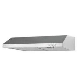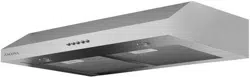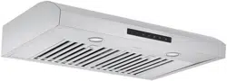

Undercabinet Range Hood
User Manual
and
Installation Instructions
IMPORTANT SAFETY INSTRUCTIONS
Carefully read the important information
regarding installation, safety and maintenance.
Keep these instructions for future reference.
MAAN1248-04
2020-04-17
— 2 —
INSTALLERS - Start Here
Safety Instructions are on pages 4 to 6 and
Installation Instructions are on pages 9 to 17.
Please perform these steps:
1. Read the safety instructions.
2. Read all instructions in the Installation section of
this manual BEFORE installing the range hood.
3. Remove all packing materials.
4. When nished, make sure to leave these instructions with the consumer.
5. Installation is to be done by a qualied technician only. However, the
ultimate responsibility for proper installation falls to the owner.
6.
Product failure due to improper installation is not covered under the Warranty.
CONSUMERS - Start Here
Safety Instructions are on pages 4 to 6 and Operating Instructions are on
pages 18 and 19.
Please perform these steps:
1. Read the safety instructions.
2. Read all instructions in the manual BEFORE operating the range hood.
3. Remove all packing materials.
4. Installation is to be done by a qualied technician only. However, the
ultimate responsibility for proper installation falls to the owner.
5.
Product failure due to improper installation is not covered under the Warranty.
Before You Begin
Hardware Note: For safety reasons, range hood mounting screws and anchors will not be
included due to the variation of cabinetry constructions and wall material. Please consult your
installation specialist regarding the optimal type of mounting screws and wall anchors to suit your
home’s construction.

— 3 —
Before You Begin ............................................................................................................................... 2
Table of Contents .............................................................................................................................. 3
Important Safety Information ............................................................................................................ 4
Included Parts ................................................................................................................................... 7
Range Hood Dimensions .................................................................................................................. 8
Specications .................................................................................................................................... 8
Installation ......................................................................................................................................... 9
Step 1 - Read the Safety Instructions ............................................................................................ 9
Step 2 - Unpack Range Hood and Prepare Tools .......................................................................... 9
Step 3 - Plan Desired Location ...................................................................................................... 9
Step 4 - Test Unit Functions .......................................................................................................... 9
Step 5 - Venting Installation Guidelines ....................................................................................... 10
Step 6 - Preparations ................................................................................................................... 12
Step 7 - Create Exterior Ventilation (New Installation Only) ......................................................... 12
Step 8 - Install Ductwork ............................................................................................................. 12
Step 9 - Attaching Vent ................................................................................................................ 13
Step 10 - Installing the Hood ....................................................................................................... 15
Step 11 - Venting ......................................................................................................................... 16
Step 12 - Install Filters ................................................................................................................. 17
Operation ........................................................................................................................................ 18
Power Settings ............................................................................................................................. 18
Lights ........................................................................................................................................... 18
Maintenance.................................................................................................................................... 19
Replacing the Light Bulbs ............................................................................................................ 19
Hood Cleaning ............................................................................................................................. 19
Range Hood Assembly ................................................................................................................... 20
Assembly ......................................................................................................................................... 21
Circuit Diagram ............................................................................................................................ 21
Blower Assembly ......................................................................................................................... 21
Electrical Assembly ...................................................................................................................... 21
Troubleshooting............................................................................................................................... 22
Use and Care Information ............................................................................................................... 23
Table of Contents

— 4 —
Important Safety Information
for qualied installers, service technicians or
persons with a similar qualied background.
Installation must be done by qualied
professionals and in accordance with all
applicable codes and standards, including
re-rated construction.
The range hood may have very sharp
edges; please wear protective gloves if it is
necessary to remove any parts for installing,
cleaning or servicing.
Activating any switch to ON position before
completing installation may cause damage or
electric shock.
person installation is recommended.
To reduce the risk of re, electric shock, or
injury to persons:
DO NOT use
and vapours.
WARNING: To Reduce The Risk Of Fire Or
Electric Shock, Do Not Use This Fan With Any
Solid-State Speed Control Device.
operation of fuel-burning equipment may be
affected by this unit’s operation. Follow the
heating equipment manufacturer’s guideline
and safety standards such as those published
by the National Fire Protection Association
(NFPA), and the American Society of Heating,
Refrigeration and Air Conditioning Engineers
(ASHRAE), and other local code authorities.
power off at service panel and lock the service
disconnecting means to prevent power from
being switched on accidentally. When the
service disconnecting means cannot be
locked, securely fasten a prominent warning
device, such as a tag, to the service panel.
properly, make sure to vent air outside. DO
NOT vent exhaust into spaces between walls,
crawl spaces, ceilings, attics or garages.
Ducted fans MUST always be vented to
the outdoors.
metal ductwork only.
and exhausting of gases through the duct to
prevent back drafting.
careful not to damage electrical wiring or other
hidden utilities.
insulated and grounded.
Old ductwork should be cleaned or replaced
if necessary to avoid the possibility of a
grease re.
Check all joints on ductwork to ensure
proper connection; all joints should be
properly taped using a certied aluminum
or foil tape.
by the manufacturer. If you have questions,
contact the vendor.
READ AND SAVE THESE
INSTRUCTIONS
READ ALL INSTRUCTIONS BEFORE USE
Read and follow all instructions before using the range hood to prevent the risk of re, electric shock,
personal injury, or damage when using the range hood or appliances with the range hood. This guide
does not cover all possible conditions that may occur. Always contact your service technician or
manufacturer about problems that you do not understand.

— 5 —
Important Safety Information
WARNING: TO REDUCE RISK OF A RANGE
TOP GREASE FIRE:
a) Never leave surface units unattended at high
settings. Boilovers cause smoking and greasy
spillovers that may ignite. Heat oils slowly on
low or medium settings.
b) Always turn range hood ON when cooking at
c)
Clean ventilating fans frequently. Grease should
not be allowed to accumulate on fan or lter.
Before servicing or cleaning unit, unplug and
disconnect the hood from the power supply.
WARNING: TO REDUCE RISK OF INJURY TO
PERSONS IN THE EVENT OF A RANGE TOP
GREASE FIRE, OBSERVE THE FOLLOWING *
a) S
MOTHER FLAMES with a close-tting
lid, cookie sheet, or metal tray, then turn
off the burner. BE CAREFUL TO PREVENT
immediately, EVACUATE AND CALL THE
FIRE DEPARTMENT.
b) NEVER PICK UP A FLAMING PAN - You may
be burned.
c) DO NOT USE WATER, including wet dishcloths
or towels - a violent steam explosion will result.
d) Use an extinguisher ONLY if:
1) You know you have a Class A, B, C
extinguisher, and you already know how to
operate it.
2) The re is small and contained in the area
where it is started.
3) The re department is being called.
4)
You can ght the re with your back to an exit.
* Based on “Kitchen Fire Safety Tips”
published by NFPA
To reduce the risk of injury to persons in the
event of a gas leaks:
DO NOT turn on the lights or any type of appliance.
gas. If you still smell gas, call the gas company
and re department.
Your safety and the safety of others is very
important. We have provided many important
safety messages in this manual and on your
appliance. Always read and obey all safety
messages. All safety messages outline any
injury, and possible risks if the instructions are not
followed.
READ AND SAVE THESE
INSTRUCTIONS

— 6 —
Important Safety Information
WARNING: TO REDUCE RISK OF A RANGE
TOP GREASE FIRE:
1. To reduce risk of re and to properly exhaust
air, be sure to duct air outside. Do not vent
exhaust air into spaces within walls or ceilings
or into attics, crawl spaces, or garages.
2. Take care when using cleaning agents or
detergents.
3. Avoid using food products that produce
4. To avoid motor bearing damage and noisy
and/or unbalanced impellers, keep drywall
spray, construction dust, etc. off power unit.
5. Your hood motor has a thermal overload
which will automatically shut off the motor if
it becomes overheated. The motor will restart
when it cools down. If the motor continues to
shut off and restart, have the hood serviced.
6. For best capture of cooking impurities, the
bottom of the hood should be a minimum of
24” (61 cm) and a maximum of 30” (76 cm)
above the cooking surface.
7. Two installers are recommended because of
8. This product is equipped with a thermostat
which may start blower automatically. To
reduce the risk of injury and to prevent power
from being switched on accidentally, switch
power off at service panel and lock or tag
service panel.
9. Use with approved wiring for electrical
connections only.
10. Please read specication label on product for
further information and requirements.
11. Use only with range hood cord-connection
kits that have been investigated and found
acceptable for use with this model range
hood.
READ AND SAVE THESE
INSTRUCTIONS

— 7 —
Included Parts
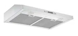
2 Filters
Hardware Note: For safety reasons, range hood mounting screws and anchors will not be included due to
the variation of cabinetry constructions and wall material. Please consult your installation specialist regarding
the optimal type of mounting screws and wall anchors to suit your home’s construction.
Metal Cover
Range Hood
Rectangle bracket
Vent-round Vent-rectangle
9 + 1 Mounting Screws
(8MM)
— 8 —
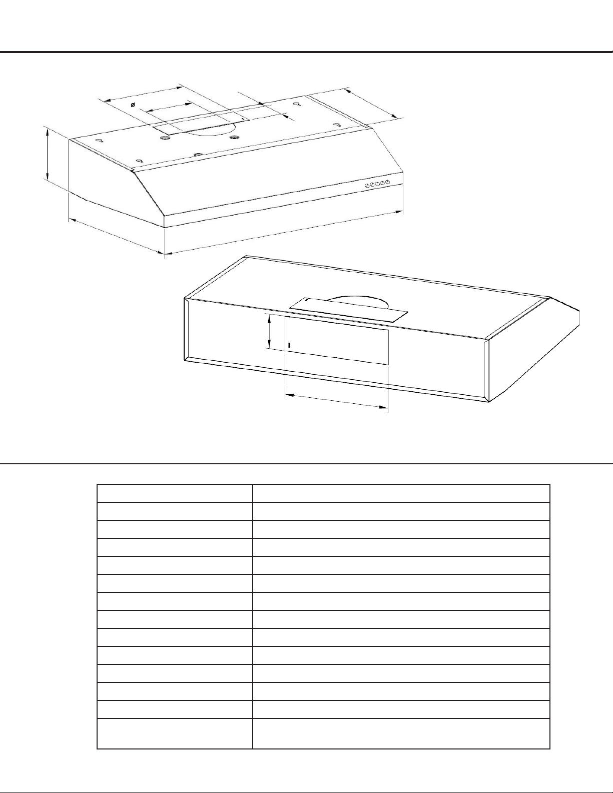
Range Hood Dimensions
Specications
Body Design Stainless Steel
Power Rating
Total Input Power 140 W (135 W + 2 × 2.5 W)
Motor Input Power 135 W
Amperage 1.3 A
Speed Control Levels 3 Speeds
Interference Protection Radio Frequency Interference Protected
Motors Single Motor
Motor Type Single Chamber Quiet
Fan type Centrifugal Squirrel Cage
Control Mechanical control panel
Filtration Aluminum lter
Illumination 2 × 2.5 W LED
6 inches (15.3 cm) round or 3 1/4 × 10 inch (8.3 cm ×
25.4 cm) rectangle, top or rear
8.3 cm
(3 1/4 in.)
25.4 cm (10 in.)
15 cm (5.9 in.)
15 cm (5.9 in.)
75 cm (29.5 in.)
50 cm (19.6 in.)
25.4 cm (10 in.)
8.3 cm
(3 1/4 in.)
30 1/2 cm (12 in.)

— 9 —
STEP 1
Read the Safety Instructions
It is very important to read the safety instructions on pages 4, 5 and 6.
IMPORTANT: It is the installer’s responsibility to comply with installation clearances.
STEP 2
Unpack Range Hood and Prepare Tools
Carefully unpack the range hood and parts. Make sure all parts are included as shown on page 7.
DO NOT remove the protective lm covering the appliance until the installation is fully completed.
Consult a qualied and trained installer or check local codes for makeup air requirement, if any.
STEP 3
Plan Desired Location
Plan a desirable location that ts all requirements in the Safety and Installation sections of this manual. Plan where
and how the ductwork will be installed.
A straight or short duct run will allow the unit to perform most efciently. Long duct runs, elbows and transitions
will reduce the performance of the unit. Each elbow is equivalent to 5 to 10 feet (1.5 m to 3 m) of straight run.
If ductwork is already installed: ensure ductwork is free from debris.
STEP 4
Test Unit Functions
Plug the unit in and test all of the functions before installing.
AC only) and turn on the range hood. Verify all operations of the range hood by referring to
Range Hood Operations.
Turn power On in control panel.
Check all lights and fan operations.
WARNINGS:
Installation
— 10 —
Installation
STEP 5
Venting Installation Guidelines
The following steps are for exterior ventilation.
Height and Clearance
IMPORTANT:
Vent system must terminate to the outside (roof or side wall).
terminate the vent system in an attic or other
enclosed area.
vent is recommended.
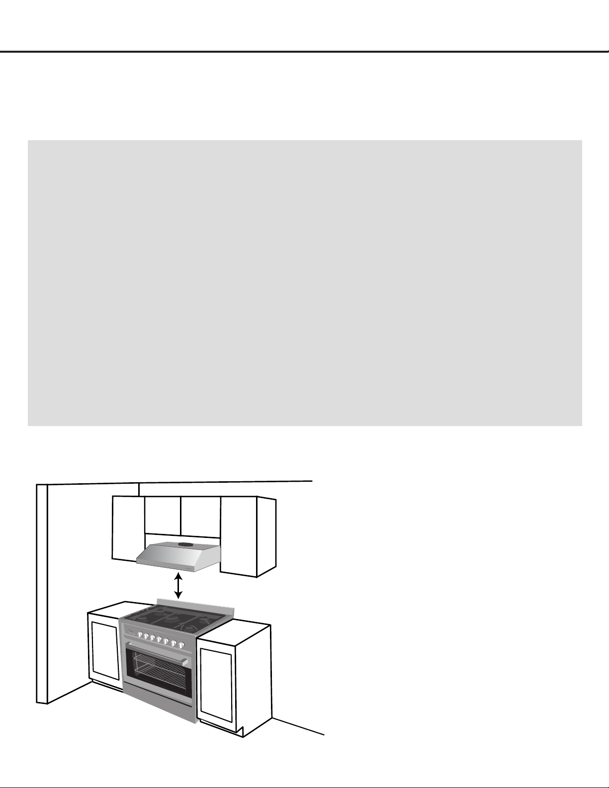
1. Distance from the floor to the ceiling
2. Distance between the floor and the countertop/stove
3.
A distance of 24 in. to 30 in. (61 cm to 76.2 cm) is
recommended between stove top and the bottom of
range hood. 30 in. (76.2 cm) minimum is required for
gas stove tops.
4. Height of hood and duct cover.
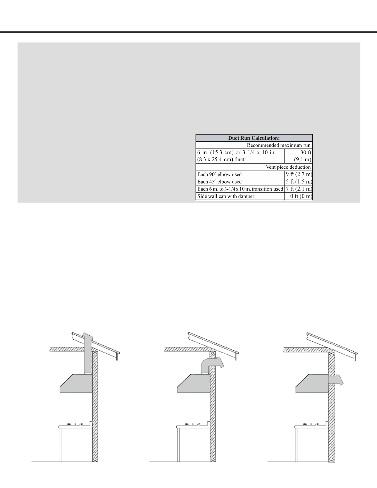
For the most efficient and quiet operation:
vertically through the roof through 6 in. (15.3 cm) or
bigger round metal/aluminum vent work.
Make sure there is a minimum of 24 in. (61 cm) of
straight vent between the elbows if more than one
elbow is used.
The length of vent system and number of elbows should be
kept to a minimum to provide efficient performance.
cap has a damper, you may remove damper flaps from
damper to increase air flow.
on top of the motor or outside.
Use silver tape or duct tape to seal all joints in the
vent system.
Use caulking to seal exterior wall or roof opening
around the cap.
24 in. (610 mm) Min / 30 in. (762 mm) Max
The minimum hood distance above cooktop must
not be less than 24 in. (61 cm). A maximum of 30
in. (76 cm) above cooktop is highly recommended
for best capture of cooking impurities. Distances
over 30 in. are at the installer and user’s discretion.
— 11 —
Installation
This range hood is factory set for venting through the roof or wall.
IMPORTANT:
NEVER exhaust air or terminate duct work into spaces between walls, crawl spaces, ceiling, attics or
garages. All exhaust must be ducted to the outside.
Use metal/aluminum duct work only.
Fasten all connections with sheet metal screws and tape all joints with certied Silver Tape or Duct Tape.
Use caulking to seal exterior wall or roof opening around the cap.
TOP VENTING
ROOF EXHAUST
TOP VENTING
WALL EXHAUST
REAR VENTING
IMPORTANT:
A minimum of 6 in. (15.3 cm) round or 3-1/4 × 10 in. (8.3
cm × 25.4 cm) rectangular duct must be used to maintain
maximum airflow efficiency.
total available duct run when using elbows, transitions
and caps.
transitions and turns. If long duct run is required,
cm) or 8 in. (20.3 cm). If a reducer is used, install a
long reducer instead of a pancake reducer. Reducing
from opening and as far apart, between two (2), as
possible.
bottom should be no less than 24-inch (61 cm) for
electric cook tops and minimum of 30-inch (76.2 cm)
for gas stove tops and no higher than 30-inch (76.2 cm)
for electric cook tops.
height. Hoods mounted too low could result in heat
may be hard to reach and will lose its performance and
efficiency.
height clearance requirements and recommended
hood mounting height above range.
Duct Run
Calculation
example:
One roof cap, two
90º elbows, and
one 45º elbow use.
0ft + 9ft + 9ft + 5ft
= 23ft used.
Deduct 23ft from
30ft, 7ft maximum
available for
straight duct run.

— 12 —
Installation
STEP 6
Preparations
NOTE: To avoid damage to your hood, prevent debris from entering the vent opening.
Determine and mark the center line on the ceiling or wall where the range hood will be installed.
Make sure there is proper clearance within the ceiling or wall for exhaust vent.
secure in the ceiling or wall.
Put a thick, protective covering over counter top, cook top or range to protect from damage or dirt.
CAUTION
If moving the cooking range is necessary to install the hood, turn OFF the power on an electric range at the main
electrical box. SHUT OFF THE GAS BEFORE MOVING A GAS RANGE
STEP 7
Create Exterior Ventilation (New Installation Only)
Choose one of the exterior venting methods shown on Page 11.
Create the exterior ventilation hole.
Following recommendations and calculations specied on Pages 10 to 11, use new aluminum/metal ducting cut
specically for the distance between the range hood damper and the exterior damper.
Fasten all connections with sheet metal screws and tape all joints with certied aluminum or foil tape.
Please check the building codes in your city to learn which tape product is recommended.
STEP 8
Install Ductwork
Use the tool to punch the wiring hole, from the 2 options for holes. Please choose hole A or hole B accordingly to wiring
requirement. (Figure #1)
Loosen 2 screws of electronic box, connect cable to range hood wiring using included wire connectors. Connect
BLACK to BLACK, WHITE to WHITE and GREEN or BARE WIRE to GREEN ground screw. DO NOT FORGET TO
CONNECT THE GROUND. (Figure #2)
Figure #1 Figure #2
A
B
— 13 —
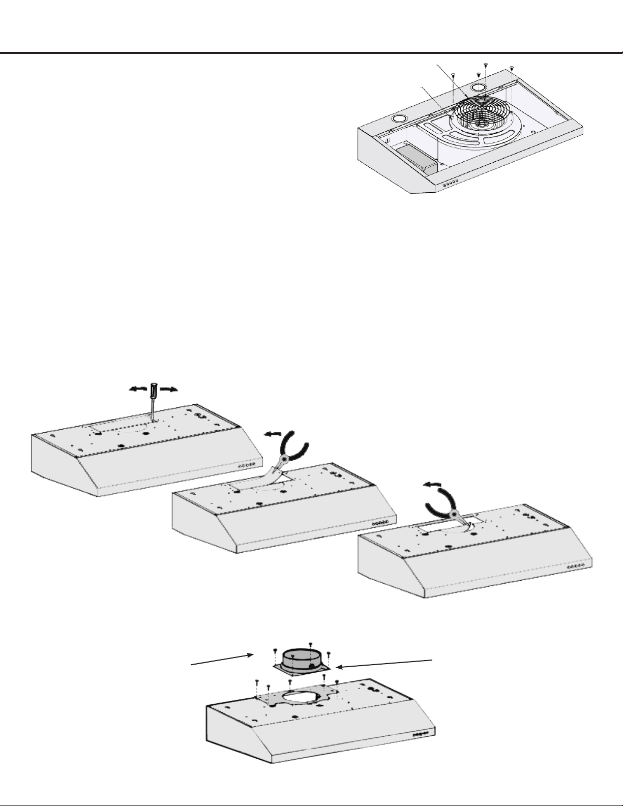
STEP 9
Attaching Vent
There are 3 venting ways, with 2 type of damper options, one is 6 in. round (15.3 cm), another is 3 1/4 × 10 in. (8.3 cm ×
25.4 cm) rectangle.
NOTE: Please only punch the vent hole you want to use. Do not punch more than 1 vent hole, otherwise, the air
power suction will be greatly affected.
Top venting using 6 in. round damper
If you require 6 in. round venting, keep the unit as provided in the packaging and install the round damper provided;
Below gures #4, #5 and #6 show how to punch the 6 in. round venting.
Then put the rectangle bracket to the top and xed by screws, position 6 in. damper on top of the unit and set in place
with screws provided (Figure #7).
Fix 6 in. damper to the
top by screws 4 pcs
4*8MM
Installation
Figure #3
Fix the rectangle bracket
by screws 5 pcs 4*8MM
A metal cover is included, to protect the motor. To install,
loosen and remove the 4 screws, then put the metal cover on
and tighten the screws.
Figure #4
Figure #5
Figure #6
Figure #7
— 14 —
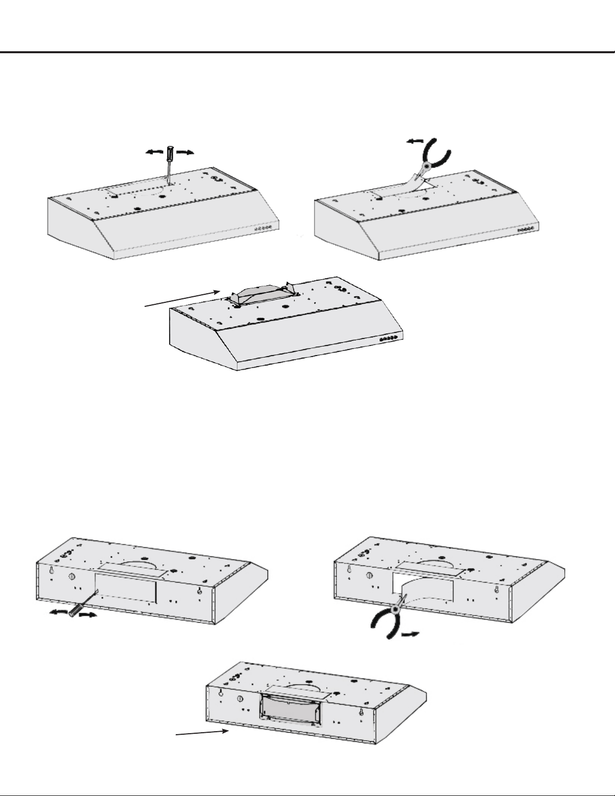
Installation
Top venting using rectangular damper
If you require rectangular top (vertical) venting simply install the rectangular damper provided (See Figure #8, #9 and
#10). Use screws 4*8MM to connect damper.
Rear venting (horizontal) using rectangular damper
and #13 to remove plate, use screws 4*8MM to connect damper.
Fix rectangle damper to the
top by screws 4*8MM
Fix rectangle damper to the
top by screws 4*8MM
Figure #8 Figure #9
Figure #10
Figure #11 Figure #12
Figure #13
— 15 —
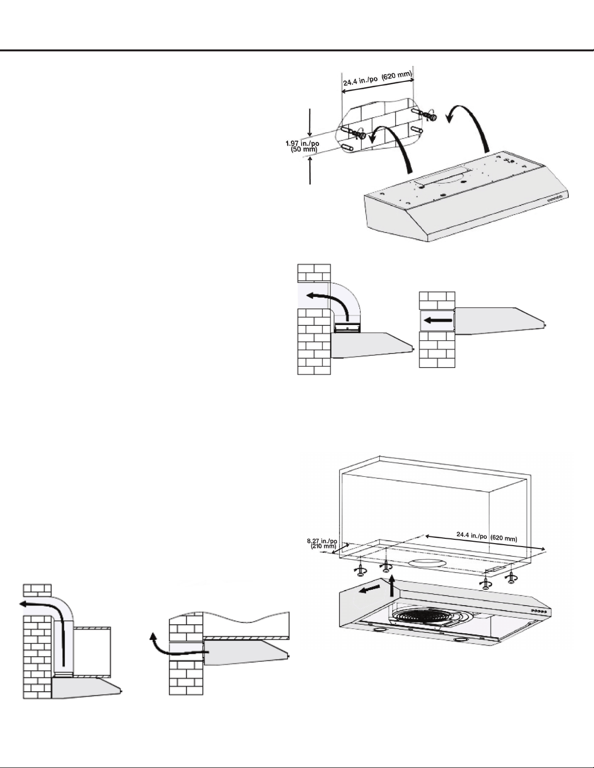
STEP 10
Installing the Hood
Method 1: Attaching the unit to the wall
The following drawings show the mounting dimensions
of the 30 in. (750 mm) .
Mark or drill 4 small holes on the mounting position
according to the dimensions on Figure #14.
Insert 4 drywall anchors into the holes, and 2 screws
into the top holes
Hang the range hood onto the screws.
Open the lter and install the inner panel in place with
safety screws.
Attach the ducting to the damper and exhaust
outdoors. (Figure #15)
Installation
Method 2: Attaching the unit to under kitchen cabinets
Mark or drill 4 small holes on the mounting position
according to the space and dimensions cited on the
following image (Figure #16).
Install 4 screws.
Open the lter, align the hole of hood to the screws, then
tighten the screws.
The following drawings show the mounting dimensions of
the 30 in. (750 mm).
Figure #14
Figure #15
Figure #16
Figure #17
Duct from top Duct from back
Duct from top Duct from back

— 16 —
STEP 11
Venting
Depending on exterior ventilation chosen (see page 10), either exit the ducting through the ceiling or wall.
seal with certied aluminum or foil tape so that it is air tight. Please check the building codes in your city to learn which
tape product is recommended.
Connect ductwork to damper. Use Duct Tape to ensure joint is sealed and air tight.
IMPORTANT:
It is the customer’s responsibility to contact a qualified electrical installer.
circuit, fused on both sides of the line.
IMPORTANT: Save this Installation Guide for electrical inspector’s use.
GROUNDING INSTRUCTIONS:
shock by providing an escape wire for the electric current.
WARNING: Improper grounding can result in a risk of electric shock.
whether the appliance is properly grounded. DO NOT use an extension cord. If the power supply cord is too short,
have a qualified electrician install an outlet near the appliance.
the fused disconnect (or circuit breaker) box through flexible armored or non-metallic sheathed copper cable. UL/
CSA listed strain relief must be provided at each end of the power supply cable. Use only with range hood cord-
connection kits that have been investigated and found acceptable for use with this model.
Installation
— 17 —
Installation
STEP 12
Install Filters
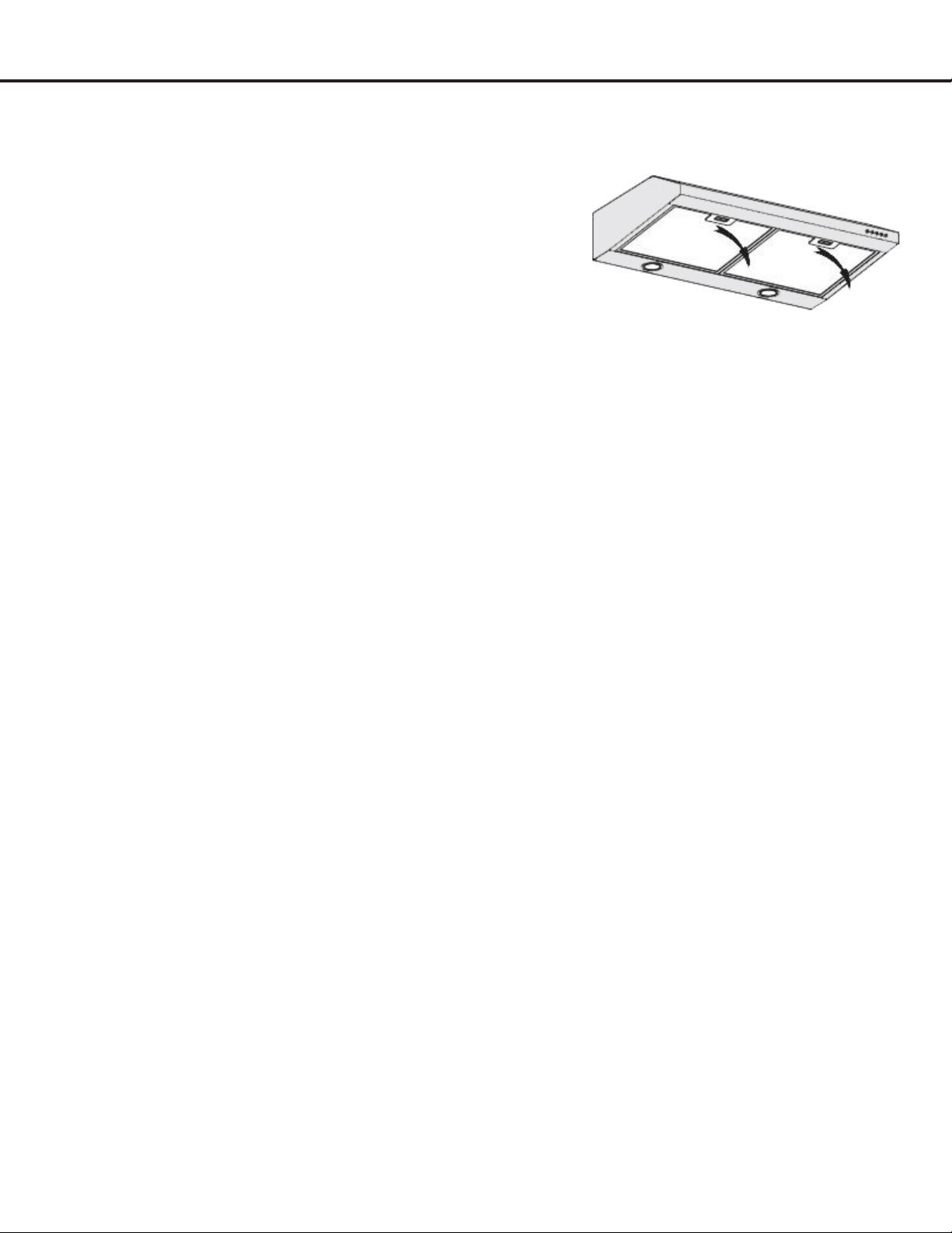
To install lters for the following four steps (See Figure #18):
Angle the lter into slots at the back of the hood.
Push the button on handle of the lter.
Release the handle once the lter ts into a resting position.
Repeat to install all lters.
Cleaning Filters
IMPORTANT: Drain oil from spacers, lters, oil tunnels, oil containers before oil and residue overow!
Remove all spacers, lters, grease tray, and oil containers and discard oil and residue.
Wash with warm soapy water. NOTE: Stainless steel lters, spacers and oil tunnel are top rack dishwasher safe.
Dry thoroughly before replacing and follow directions for installation in reverse.
Filters should be cleaned after every 30 hours of use.
Should lters wear out due to age and prolonged use, replace with a new lter.
Figure #18
— 18 —
Operation
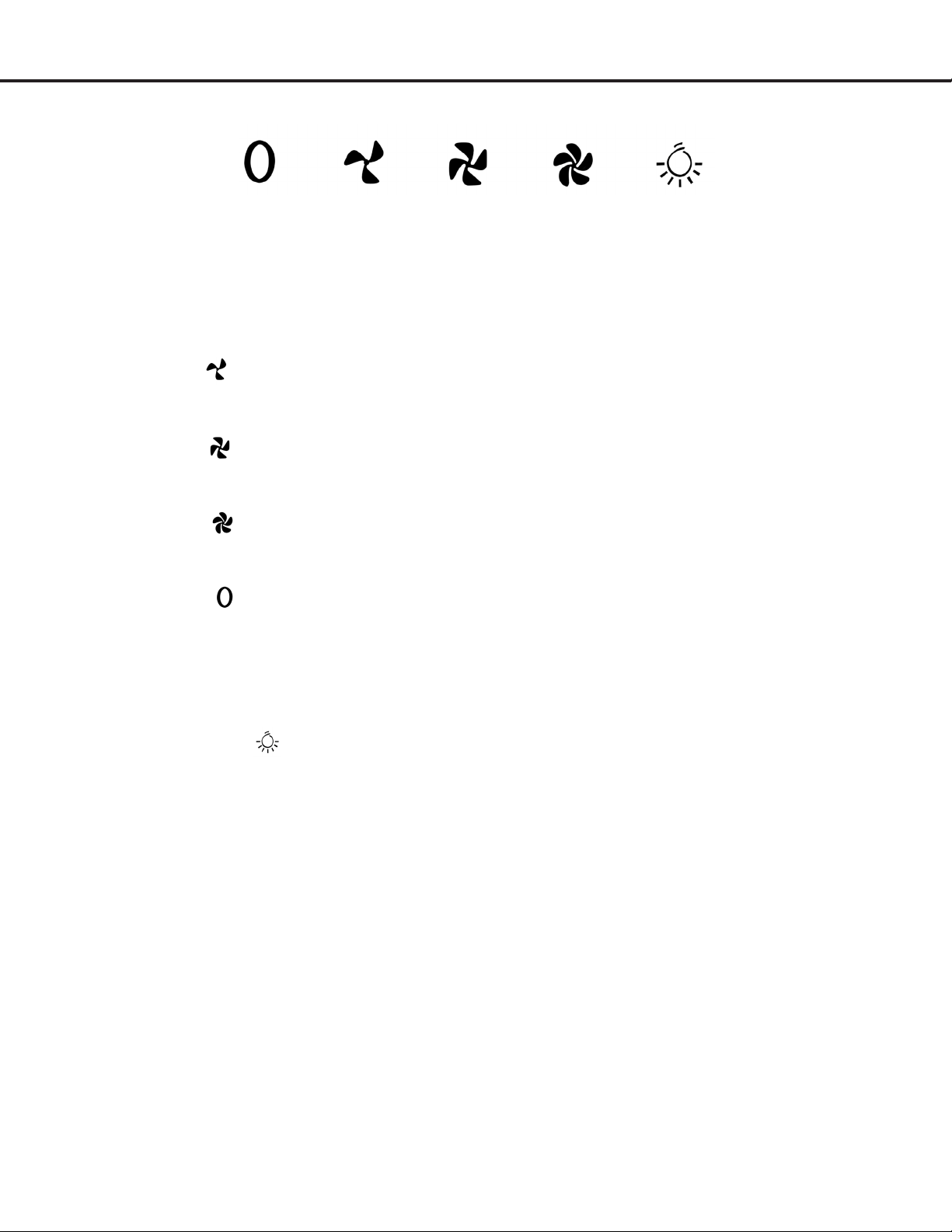
Power Settings
u
Press the button once and the motor starts to
operate at Low speed.
v
Press the button and the motor will reach Medium
speed.
w
Press the button the motor will reach High
speed.
x
Press the button to turn the fan off.
Lights
u
Press the light button to turn LED lights on and
off.
Low
Speed
Medium
Speed
Light
High
Speed
Stop

— 19 —
Proper maintenance of the Range Hood will ensure proper performance of the unit.
Use a warm detergent solution. Grease lters are dishwasher safe.
Stainless steel is one of the easiest materials to keep clean. Occasional care will help preserve its appearance.
Cleaning tips:
Hot water with soap or detergent is all that is usually required.
Follow all cleaning by rinsing with clear water. Wipe dry with a clean, soft cloth to avoid water marks.
For discolorations or deposits that persist, use a non-scratching household cleanser or stainless steel polishing powder
with a little water and a soft cloth.
For stubborn cases, use a plastic scouring pad or soft bristle brush with cleanser and water. Rub lightly in direction of
polishing lines or “grain” of the stainless nish. Avoid using too much pressure, which may mar the surface.
DO NOT allow deposits to remain on surface for long periods of time.
DO NOT use ordinary steel wool or steel brushes. Small bits of steel may adhere to the surface causing rust.
DO NOT allow salt solutions, disinfectants, bleaches, or cleaning compounds to remain in contact with stainless steel
for extended periods. Many of these compounds contain chemicals which may be harmful. Rinse with water after
exposure and wipe dry with a clean cloth.
Painted surfaces should be cleaned with warm water and mild detergent only.
Maintenance
Replacing the Light Bulbs
u
Make sure the range hood is unplugged or turn OFF
breaker.
v
Open the lter and nd the spring of the light.
w
Push the spring and the lights will slip out.
CAUTION: BULB MAY BE HOT, PLEASE TAKE OUT
THE BULB WHEN THE BULB IS COMPLETELY
COOL!
x
Replace with a 10.2 Volt, 2.5 Watt max, LED lights.
Do not touch replacement bulb with bare hands!
y
Turn ON breaker and range hood to test for
operation.
IMPORTANT:
ALWAYS SWITCH OFF THE ELECTRICITY SUPPLY AT THE MAIN PANEL BEFORE CARRYING OUT ANY OPERATION
ON THE APPLIANCE.
Hood Cleaning
— 20 —
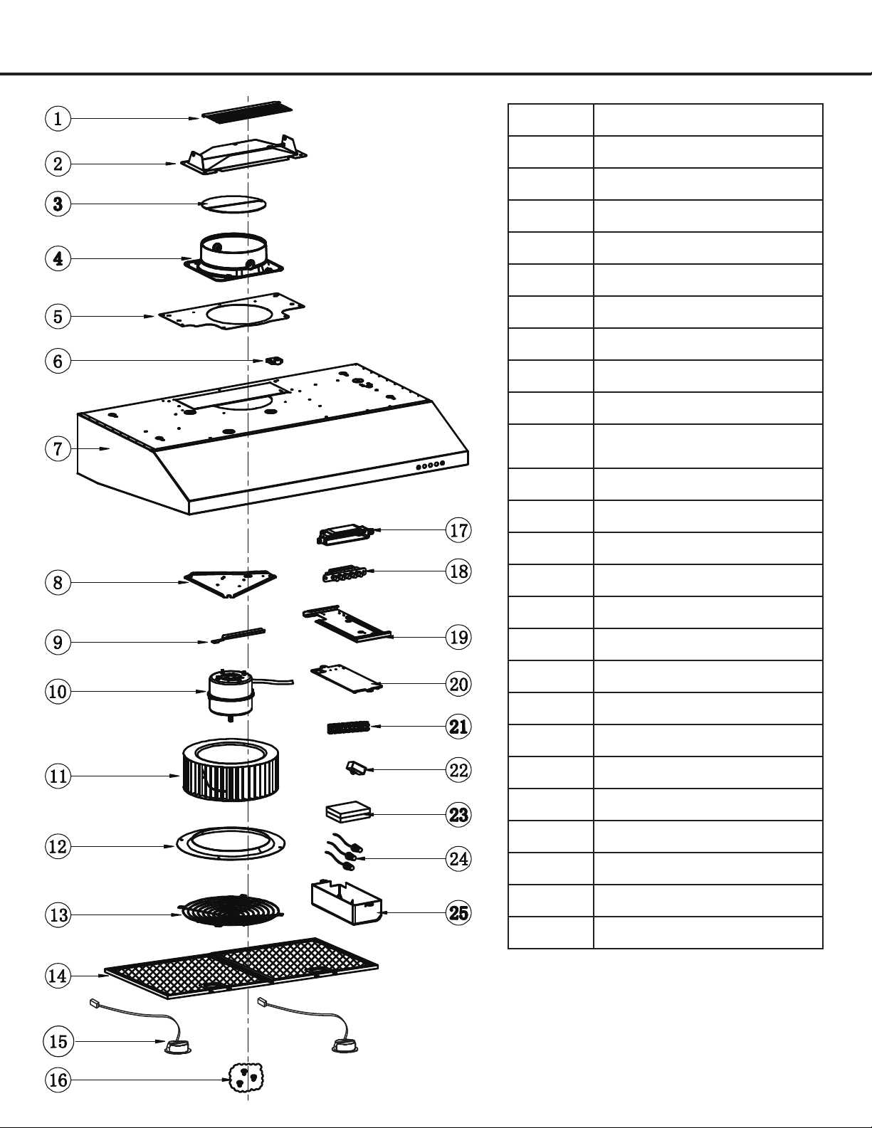
Range Hood Assembly
Number Part
1
2 Vent (rectangle)
3
4 Vent (round)
5 Rectangle bracket
6 Fixed cover
7 Housing
8 Motor bracket
9 Slot
10 Blower assembly (include
motor)
11 Wheel
12 Metal ring
13 Metal cover
14 Filter (1 set with 2 pcs)
15 LED lights (1 set with 2 pcs)
16 Screw bag
17 Control box
18 Controller assembly
19 Bracket of electronic box
20 Base of electronic box
21 Wiring connector
22 Capacitor
23 Transformer
24 Connector
25 Electronic box
— 20 —
Range Hood Assembly
Number Part
1 Damper
2 Vent (rectangle)
3 Damper
4 Vent (round)
5 Rectangle bracket
6 Fixed cover
7 Motor housing
8 Motor bracket
9 Slot
10 Blower assembly (include
motor)
11 Wheel
12 Metal ring
13 Metal cover
14 Filter (1 set with 2 pcs)
15 LED lights (1 set with 2 pcs)
16 Screw bag
17 Control box
18 Controller assembly
19 Bracket of electronic box
20 Base of electronic box
21 Wiring connector
22 Capacitor
23 Transformer
24 Connector
25 Electronic box
— 21 —
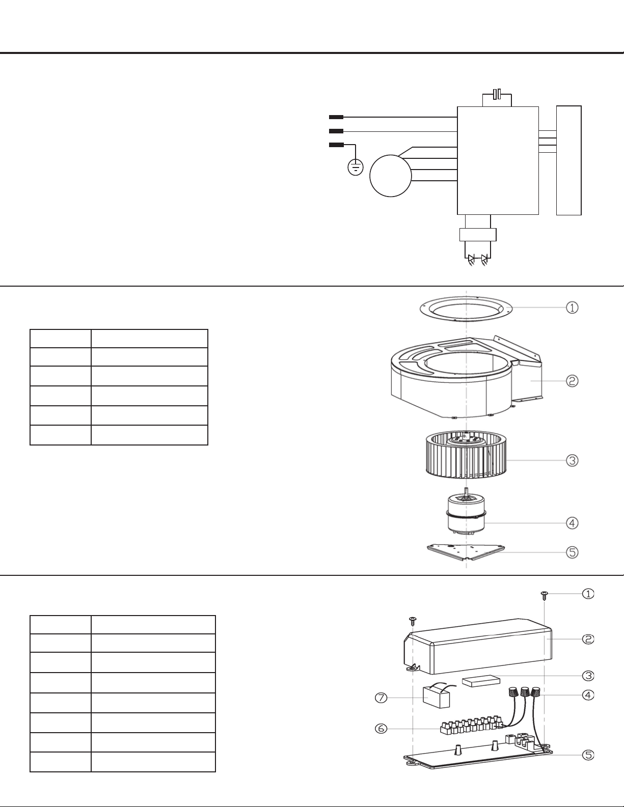
Assembly
Circuit Diagram
Blower Assembly
Electrical Assembly
Number Part
1 Screws
2 Box
3 Transformer
4 Terminal
5 Box base
6 Connector
7 Capacitor
Number Part
1 Ring
2 Blower
3 Propeller
4 Motor
5 Bracket of Motor
b
tsopgnidni
Push Button
AC 0V 60Hz12
L
N
E
+
_
Driver
M
Capacitor
— 22 —
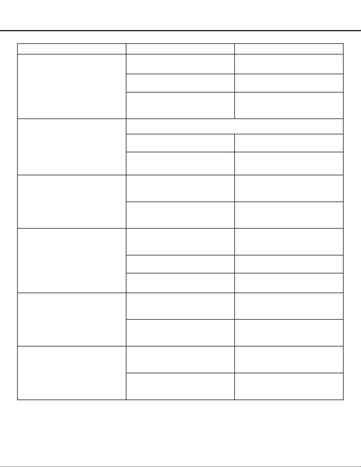
Troubleshooting
Problem Cause Solution
Light on, but motor does not
work
The motor blocked Get rid of the blocking
The capacitor is damaged Have capacitor replaced
The motor bearings are jammed
or damaged
Have motor replaced
Light does not work, motor does
not work
Beside the mentioned above, check the following:
Light is damaged Replace lights
Wires are loose or disconnected Connect the wires as per the
electric diagram
Oil leakage The one-way valve and the air
ventilation entrance are not
tightly sealed
Take down the one way valve
and seal with glue
Leakage from the connection of
U-shaped section and cover
Take U-shaped section down
and seal with soap or paint
Hood body shakes The motor damaged and causes
shaking
Have motor replaced
The motor is not tightly attached Tighten motor
The body is not tight Tighten the body
Insufcient suction The hood is installed too high
(too much distance between
hood and cooktop)
Install hood at the appropriate
height
Too much ventilation from open
doors or windows
Close doors or windows
The hood is slanted The xing screw is not tight
enough
Place hood in its proper position
and tighten the xing screw
The hanging screw is not tight
enough
Place hood in its proper position
and tighten the hanging screw

— 23 —
Use and Care Information
Operations
Read and understand all instructions and warnings in this manual before operating the appliance. Save these
instructions for future reference.
Always leave safety grills and lters in place. Without these components, operating fans could catch on to hair, ngers
and loose clothing.
NEVER dispose cigarette ashes, ignitable substances, or any foreign objects into fans.
NEVER leave cooking unattended. When frying, oil in the pan can easily overheat and catch re. The risk of self
combustion is higher when the oil has been used several times.
Cleaning
grease and residue build-up at all times to prevent possible res.
Filters must be cleaned periodically and free from accumulation of cooking residue (see Cleaning Instructions below).
Old and worn lters must be replaced immediately.
DO NOT operate fans when lters are removed. Never disassemble parts to clean without proper instructions.
Disassembly is recommended to be performed by qualied personnel only. Read and understand all instructions and
warnings in this manual before proceeding.
SAFETY WARNING: Never put your hand into area housing the fan while the fan is operating!
For optimal operation, clean range hood and all bafe/spacer/lter/grease tray/oil container regularly. Regular care
will help preserve the appearance of the range hood.
Cleaning Exterior Surfaces
Clean periodically with hot soapy water and clean cotton cloth. DO NOT use corrosive or abrasive detergent (e.g. Comet
Power Scrub®, EZ-Off® oven cleaner), or steel wool/scoring pads, which will scratch and damage the stainless steel
surface. For heavier soil use liquid degrease such as “Formula 409®” or “Fantastic®” brand cleaner.
If hood looks splotchy (stainless steel hood), use a stainless steel cleaner to clean the surface of the hood. Avoid getting
cleaning solution onto or into the control panel. Follow directions of the stainless steel cleaner. CAUTION: DO NOT
leave on too long as this may cause damage to hood nish. Use soft towel to wipe off the cleaning solution, gently
rub off any stubborn spots. Use dry soft towel to dry the hood.
After cleaning, you may use non abrasive stainless steel polish such as 3M® or ZEP®, to polish and buff out the
stainless luster and grain. Always scrub lightly, with clean cotton cloth, and with the grain.
DO NOT allow deposits to accumulate or remain on the hood.
DO NOT use ordinary steel wool or steel brushes. Small bits of steel may adhere to the surface and cause rusting.
DO NOT allow salt solutions, disinfectants, bleaches, or cleaning compounds to remain in contact with stainless steel
for extended periods. Many of these compounds contain chemicals, which may be harmful.
Rinse with water after exposure to these compounds and wipe dry with a clean cloth.

— 24 —
Please register your product warranty by visiting the Ancona Home website.
Canada & USA
Phone: 1-888-686-0778
Fax: 800-350-8563
Email: [email protected]
Website: www.anconahome.com
Ancona is in association with Mr Appliance for all after sales service calls.
Please contact their service provider or visit their website:
Phone: 1-888-998-2011
Website: www.mrappliance.com
© 2020 Copyright of Ancona Home. All rights reserved. This material may not be reproduced, displayed, modied or distributed.
MAAN1248-04