Portable Projector
VT800
User’s Manual

2nd edition, July 2008
• IBM is a trademark or registered trademark of International Business Machines Corporation.
• Macintosh, Mac OS X and PowerBook are trademarks of Apple Inc., registered in the U.S. and other countries.
• Microsoft, Windows and PowerPoint are trademarks or registered trademarks of Microsoft Corporation.
• Windows Vista is either a registered trademark or trademark of Microsoft Corporation in the United States and/
or other countries.
• VESA is a registered trademark of Video Electronics Standards Association.
• All Rights Reserved. Corel, the Corel logo, Ulead, the Ulead logo, Ulead Photo Explorer, InterVideo, the Inter-
Video logo, are trademarks or registered trademarks of Corel Corporation and/or its subsidiaries.
• HQV is a registered trademark of Silicon Optix Inc.
• HDMI, the HDMI Logo and High-De nition Multimedia Interface are trademarks or registered trademarks of
HDMI Licensing LLC.
• Trademark PJLink is a trademark applied for trademark rights in Japan, the United States of America and other
countries and areas.
• Other product and company names mentioned in this user’s manual may be the trademarks or registered trade-
marks of their respective holders.
NOTES
(1) The contents of this guide may not be reprinted in part or whole without permission.
(2) The contents of this guide are subject to change without notice.
(3) Great care has been taken in the preparation of this manual; however, should you notice any questionable
points, errors or omissions, please contact us.
(4) Notwithstanding article (3), NEC will not be responsible for any claims on loss of profit or other matters
deemed to result from using the Projector.
i
Important Information
Safety Cautions
Precautions
Please read this manual carefully before using your NEC VT800 projector and keep the manual handy for future
reference.
CAUTION
To turn off main power, be sure to remove the plug from power outlet.
The power outlet socket should be installed as near to the equipment as possible, and should be eas-
ily accessible.
CAUTION
TO PREVENT SHOCK, DO NOT OPEN THE CABINET.
THERE ARE HIGH-VOLTAGE COMPONENTS INSIDE.
REFER SERVICING TO QUALIFIED SERVICE PERSONNEL.
This symbol warns the user that uninsulated voltage within the unit may be suf cient to cause electrical
shock. Therefore, it is dangerous to make any kind of contact with any part inside of the unit.
This symbol alerts the user that important information concerning the operation and maintenance of
this unit has been provided.
The information should be read carefully to avoid problems.
WARNING: TO PREVENT FIRE OR SHOCK, DO NOT EXPOSE THIS UNIT TO RAIN OR MOISTURE.
DO NOT USE THIS UNIT’S PLUG WITH AN EXTENSION CORD OR IN AN OUTLET UNLESS ALL THE
PRONGS CAN BE FULLY INSERTED.
DOC Compliance Notice (for Canada only)
This Class B digital apparatus meets all requirements of the Canadian Interference-Causing Equipment Regula-
tions.
Acoustic Noise Information Ordinance-3. GSGV (for Germany only):
The sound pressure level is less than 70 dB (A) according to ISO 3744 or ISO 7779.
WARNING TO CALIFORNIA RESIDENTS:
Handling the cables supplied with this product will expose you to lead, a chemical known to the State of Califor-
nia to cause birth defects or other reproductive harm. WASH HANDS AFTER HANDLING.
CAUTION
Avoid displaying stationary images for a prolonged period of time.
Doing so can result in these images being temporarily sustained on the surface of the LCD panel.
If this should happen, continue to use your projector. The static background from previous images will
disappear.

ii
Important Information
EU-wide legislation as implemented in each Member State requires that used electrical and electronic
products carrying the mark (left) must be disposed of separately from normal household waste. This
includes projectors and their electrical accessories or lamps. When you dispose of such products,
please follow the guidance of your local authority and/or ask the shop where you purchased the prod-
uct.
After collecting the used products, they are reused and recycled in a proper way. This effort will help
us reduce the wastes as well as the negative impact such as mercury contained in a lamp to the hu-
man health and the environment at the minimum level.
The mark on the electrical and electronic products only applies to the current European Union Mem-
ber States.
Disposing of your used product
iii
Important Information
RF Interference (for USA only)
WARNING
The Federal Communications Commission does not allow any modi cations or changes to the unit EXCEPT
those speci ed by NEC Display Solutions of America, Inc. in this manual. Failure to comply with this govern-
ment regulation could void your right to operate this equipment. This equipment has been tested and found
to comply with the limits for a Class B digital device, pursuant to Part 15 of the FCC Rules. These limits are
designed to provide reasonable protection against harmful interference in a residential installation. This equip-
ment generates, uses, and can radiate radio frequency energy and, if not installed and used in accordance with
the instructions, may cause harmful interference to radio communications. However, there is no guarantee that
interference will not occur in a particular installation.
If this equipment does cause harmful interference to radio or television reception, which can be determined by
turning the equipment off and on, the user is encouraged to try to correct the interference by one or more of the
following measures:
• Reorient or relocate the receiving antenna.
• Increase the separation between the equipment and receiver.
• Connect the equipment into an outlet on a circuit different from that to which the receiver is connected.
• Consult the dealer or an experienced radio / TV technician for help.
For UK only: In UK, a BS approved power cable with moulded plug has a Black ( ve Amps) fuse installed for use
with this equipment. If a power cable is not supplied with this equipment please contact your supplier.
Important Safeguards
These safety instructions are to ensure the long life of your projector and to prevent re and shock. Please read
them carefully and heed all warnings.
Installation
• Do not place the projector in the following conditions:
- on an unstable cart, stand, or table.
- near water, baths or damp rooms.
- in direct sunlight, near heaters or heat radiating appliances.
- in a dusty, smoky or steamy environment.
- on a sheet of paper or cloth, rugs or carpets.
• If you wish to have the projector installed on the ceiling:
- Do not attempt to install the projector yourself.
- The projector must be installed by quali ed technicians in order to ensure proper operation and reduce the
risk of bodily injury.
- In addition, the ceiling must be strong enough to support the projector and the installation must be in accor-
dance with any local building codes.
- Please consult your dealer for more information.
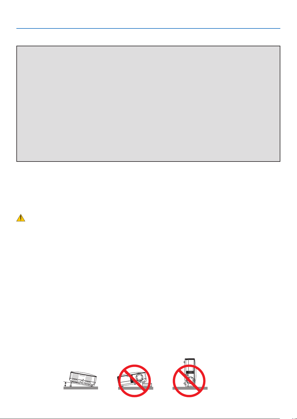
10˚
Place the projector in a horizontal position
The tilt angle of the projector should not exceed 10 degrees, nor should the projector be installed in any way other
than the desktop and ceiling mount, otherwise lamp life could decrease dramatically.

iv
Important Information
Fire and Shock Precautions
• Ensure that there is suf cient ventilation and that vents are unobstructed to prevent the build-up of heat inside
your projector. Allow at least 4 inches (10cm) of space between your projector and a wall.
• Do not try to touch the ventilation outlet as it can become heated while the projector is turned on.
• Prevent foreign objects such as paper clips and bits of paper from falling into your projector. Do not attempt to
retrieve any objects that might fall into your projector. Do not insert any metal objects such as a wire or screw-
driver into your project. If something should fall into your projector, disconnect it immediately and have the ob-
ject removed by a quali ed service personnel.
• Do not place any objects on top of the projector.
• Do not touch the power plug during a thunderstorm. Doing so can cause electrical shock or re.
• The projector is designed to operate on a power supply of 100-240V AC 50/60 Hz. Ensure that your power
supply ts this requirement before attempting to use your projector.
• Do not look into the lens while the projector is on. Serious damage to your eyes could result.
• Keep any items such as magnifying glass out of the light path of the projector. The light being projected from
the lens is extensive, therefore any kind of abnormal objects that can redirect light coming out of the lens, can
cause unpredictable outcome such as re or injury to the eyes.
• Do not cover the lens with the black lens cap or equivalent while the projector is on. Doing so can lead to melt-
ing of the cap and possibly burning your hands due to the heat emitted from the light output.
• Do not place any objects, which are easily affected by heat, in front of the projector lens or a projector exhaust
vent.
Doing so could lead to the object melting or getting your hands burned from the heat that is emitted from the
light output and exhaust.
• Handle the power cable carefully. A damaged or frayed power cable can cause electric shock or re.
- Do not use any power cables than the supplied one.
- Do not bend or tug the power cable excessively.
- Do not place the power cable under the projector, or any heavy object.
- Do not cover the power cable with other soft materials such as rugs.
- Do not heat the power cable.
- Do not handle the power plug with wet hands.
• Turn off the projector, unplug the power cable and have the projector serviced by a quali ed service personnel
under the following conditions:
- When the power cable or plug is damaged or frayed.
- If liquid has been spilled into the projector, or if it has been exposed to rain or water.
- If the projector does not operate normally when you follow the instructions described in this user’s manual.
- If the projector has been dropped or the cabinet has been damaged.
- If the projector exhibits a distinct change in performance, indicating a need for service.
• Disconnect the power cable and any other cables before carrying the projector
• Turn off the projector and unplug the power cable before cleaning the cabinet or replacing the lamp.
• Turn off the projector and unplug the power cable if the projector is not to be used for an extended period of
time.
• When using a LAN cable:
For safety, do not connect to the connector for peripheral device wiring that might have excessive voltage.

v
Important Information
CAUTION
• Do not use the tilt-foot for purposes other than originally intended. Misuses such as using the tilt foot to carry
or hang (from the wall or ceiling) the projector can cause damage to the projector.
• Do not send the projector in a soft case by parcel delivery service or cargo shipment. The projector inside
the soft case could be damaged.
• Select [HIGH] in Fan mode if you continue to use the projector for consecutive days. (From the menu, select
[SETUP] → [OPTIONS] → [FAN MODE] → [HIGH].)
• Do not unplug the power cable from the wall outlet or projector when the projector is powered on. Doing so
can cause damage to the AC IN connector of the projector and (or) the prong plug of the power cable.
To turn off the AC power supply when the projector is powered on, use a power strip equipped with a switch
and a breaker.
• Do not try to touch the ventilation outlet on the left front (when seen from the front) as it can become heated
while the projector is turned on and immediately after the projector is turned off.
• Do not turn off the AC power for 60 seconds after the lamp is turned on and while the POWER indicator is
blinking green. Doing so could cause premature lamp failure.
Remote Control Precautions
• Handle the remote control carefully.
• If the remote control gets wet, wipe it dry immediately.
• Avoid excessive heat and humidity.
• Do not heat, take apart, or throw batteries into re.
• If you will not be using the remote control for a long time, remove the batteries.
• Ensure that you have the batteries’ polarity (+/–) aligned correctly.
• Do not use new and old batteries together, or use different types of batteries together.
• Dispose of used batteries according to your local regulations.
Lamp Replacement
• To replace the lamp, follow all instructions provided on page
117.
• Be sure to replace the lamp when the message [THE LAMP HAS REACHED THE END OF ITS USABLE
LIFE. PLEASE REPLACE THE LAMP.] appears. If you continue to use the lamp after the lamp has reached
the end of its usable life, the lamp bulb may shatter, and pieces of glass may be scattered in the lamp case. Do
not touch them as the pieces of glass may cause injury.
If this happens, contact your dealer for lamp replacement.
A Lamp Characteristic
The projector has a high-pressure mercury lamp as a light source.
A lamp has a characteristic that its brightness gradually decreases with age. Also repeatedly turning the lamp on
and off will increase the possibility of its lower brightness.
CAUTION:
When removing the lamp from a ceiling-mounted projector, make sure that no one is under the projector. Glass
fragments could fall if the lamp has been burned out.

vi
Important Information
About High Altitude mode
• Set [FAN MODE] to [HIGH ALTITUDE] when using the projector at altitudes approximately 5500 feet/1600 me-
ters or higher.
• Using the projector at altitudes approximately 5500 feet/1600 meters or higher without setting to [HIGH ALTI-
TUDE] can cause the projector to overheat and the protector could shut down. If this happens, wait a couple
minutes and turn on the projector.
• Using the projector at altitudes less than approximately 5500 feet/1600 meters and setting to [HIGH ALTI-
TUDE] can cause the lamp to overcool, causing the image to icker. Switch [FAN MODE] to [AUTO].
• Using the projector at altitudes approximately 5500 feet/1600 meters or higher can shorten the life of optical
components such as the lamp.
About Copyright of original projected pictures:
Please note that using this projector for the purpose of commercial gain or the attraction of public attention in a
venue such as a coffee shop or hotel and employing compression or expansion of the screen image with the fol-
lowing functions may raise concern about the infringement of copyrights which are protected by copyright law.
[ASPECT RATIO], [SCREEN] setting, [KEYSTONE], [CONERSTONE], [PIP/SIDE BY SIDE], Magnifying feature
and other similar features.

vii
Table of Contents
Important Information
............................................................................................ i
1. Introduction
.......................................................................................................... 1
❶ What’s in the Box?......................................................................................................... 1
❷ Introduction to the Projector .......................................................................................... 2
Congratulations on Your Purchase of the Projector................................................. 2
Features you’ll enjoy : .............................................................................................. 2
About this user’s manual.......................................................................................... 3
❸ Part Names of the Projector .......................................................................................... 4
Front/Top ................................................................................................................. 4
Rear ......................................................................................................................... 4
Bottom...................................................................................................................... 5
Top Features............................................................................................................ 6
Terminal Panel Features.......................................................................................... 7
❹ Part Names of the Remote Control ............................................................................... 8
Battery Installation ................................................................................................... 9
Operating Range for Wireless Remote Control ....................................................... 9
Remote Control Precautions .................................................................................... 9
2. Installation and Connections
................................................................... 10
❶ Setting Up the Screen and the Projector ..................................................................... 10
Selecting a Location............................................................................................... 10
❷ Making Connections .................................................................................................... 11
Connecting Your PC or Macintosh Computer ........................................................ 11
Connecting an External Monitor............................................................................. 13
Connecting Your HDMI Compatible Equipment ..................................................... 14
Connecting Your DVD Player with Component Output .......................................... 15
Connecting Your VCR............................................................................................ 16
Connecting to a Network........................................................................................ 17
Connecting the Supplied Power Cable .................................................................. 19
3. Projecting an Image (Basic Operation)
.............................................. 20
❶ Turning on the Projector .............................................................................................. 20
Note on Startup screen (Menu Language Select screen) ...................................... 21
❷ Selecting a Source ...................................................................................................... 22
Selecting the computer or video source................................................................. 22
❸ Adjusting the Picture Size and Position ....................................................................... 23
Adjusting the focus (Focus ring) ............................................................................ 24
Finely adjusting the size of an image (Zoom lever) ............................................... 24
Adjusting the Tilt Foot ............................................................................................ 25
❹ Correcting Keystone Distortion .................................................................................... 26
❺ Optimizing an RGB Image Automatically .................................................................... 28
Adjusting the Image Using Auto Adjust.................................................................. 28
❻ Adjusting Volume Up & Down ..................................................................................... 28
❼ Turning off the Projector .............................................................................................. 29
❽ After Use......................................................................................................................30

viii
Table of Contents
4. Convenient Features
..................................................................................... 31
❶ Turning Off the Image and Sound ............................................................................... 31
❷ Freezing a Picture ....................................................................................................... 31
❸ Enlarging and Moving a Picture................................................................................... 31
❹ Changing Lamp Mode ................................................................................................. 32
❺ Getting Integrated Help ............................................................................................... 32
❻ Using a USB Mouse .................................................................................................... 33
Operate the Menus using the USB mouse ............................................................ 33
❼ Using the Optional Remote Mouse Receiver (NP01MR) ............................................ 34
❽ Correcting Horizontal and Vertical Keystone Distortion (Cornerstone) ....................... 36
Cornerstone ........................................................................................................... 36
❾ Displaying Two Pictures at the Same Time ................................................................. 39
Selecting the PIP or SIDE BY SIDE Mode [MODE] ............................................... 39
POSITION ............................................................................................................. 40
❿ Preventing Unauthorized Use of the Projector ............................................................ 41
Assigning a Keyword for the rst time.................................................................... 41
Checking If Security is enabled.............................................................................. 44
Disabling the Security ............................................................................................ 45
⓫ Limiting Access Level to Available Menu Items ........................................................... 46
⓬ Operation Using an HTTP Browser ............................................................................. 49
Overview ................................................................................................................ 49
Preparation Before Use ......................................................................................... 49
Handling of the Address for Operation via a Browser ............................................ 49
Structure of the HTTP Server ................................................................................ 50
⓭ Projecting Your Computer’s Screen Image from the Projector via a Network
[NETWORK PROJECTOR] ................................................................................... 52
⓮ Using the Projector to Operate Your Computer via a Network
[REMOTE DESKTOP] ........................................................................................... 56
5. Using the Viewer
............................................................................................. 61
❶ Making the Most out of the Viewer Function ............................................................... 61
Features ................................................................................................................. 61
Easy to use ............................................................................................................ 61
Simple utility software (for computer) ..................................................................... 61
❷ Saving data to a USB memory device ......................................................................... 61
Using Ulead Photo Explorer 8.0 (optional)............................................................. 61
Using Windows Explorer to save les .................................................................... 61
❸ Operating the Viewer Function from the Projector (playback) ..................................... 62
Projecting slides (Viewer) ...................................................................................... 62
Operating Viewer Menu ......................................................................................... 62
Setting Option for Viewer ....................................................................................... 64
THUMBNAILS menu .............................................................................................. 64
Exiting Viewer ........................................................................................................ 65
❹ Changing Background Logo ........................................................................................ 66

ix
Table of Contents
6. Using On-Screen Menu
................................................................................ 67
❶ Using the Menus.......................................................................................................... 67
Using ADVANCED menu and BASIC menu .......................................................... 68
Entering alphanumeric characters by using Software Keyboard ........................... 68
❷ Menu tree .................................................................................................................... 69
❸ Menu Elements............................................................................................................ 71
❹ Menu Descriptions & Functions [SOURCE] ................................................................ 72
COMPUTER 1 and 2 ............................................................................................. 72
HDMI ...................................................................................................................... 72
VIDEO .................................................................................................................... 72
S-VIDEO ................................................................................................................ 72
VIEWER ................................................................................................................. 72
NETWORK............................................................................................................. 72
ENTRY LIST .......................................................................................................... 72
❺ Menu Descriptions & Functions [ADJUST] .................................................................. 75
[PICTURE] ............................................................................................................. 75
[IMAGE OPTIONS] ................................................................................................ 78
[VIDEO] .................................................................................................................. 82
[AUDIO].................................................................................................................. 83
❻ Menu Descriptions & Functions [SETUP] .................................................................... 84
[BASIC] .................................................................................................................. 84
[MENU] .................................................................................................................. 92
[INSTALLATION(1)] ............................................................................................... 93
[INSTALLATION(2)] ............................................................................................... 95
[OPTIONS] ........................................................................................................... 108
❼ Menu Descriptions & Functions [INFO.] .................................................................... 110
[USAGE TIME] ..................................................................................................... 110
[SOURCE(1)] ....................................................................................................... 111
[SOURCE(2)] ....................................................................................................... 111
[WIRED LAN] ....................................................................................................... 112
[VERSION(1)] ...................................................................................................... 112
[VERSION(2)] ...................................................................................................... 112
❽ Menu Descriptions & Functions [RESET] .................................................................. 113
Returning to Factory Default ................................................................................ 113
7. Maintenance
.................................................................................................... 114
❶ Cleaning or Replacing the Filter ................................................................................ 114
❷ Cleaning the Cabinet and the Lens ........................................................................... 116
❸ Replacing the Lamp................................................................................................... 117

x
Table of Contents
8. Appendix
............................................................................................................. 120
❶ Troubleshooting ......................................................................................................... 120
Indicator Messages .............................................................................................. 120
❷ Speci cations ............................................................................................................ 123
❸ Cabinet Dimensions .................................................................................................. 125
❹ Screen Size and Projection Distance ........................................................................ 126
❺ Pin Assignments of D-Sub COMPUTER 1/2 Input Connector .................................. 128
Mini D-Sub 15 Pin Connector .............................................................................. 128
❻ Compatible Input Signal List ...................................................................................... 129
❼ PC Control Codes and Cable Connection ................................................................. 130
PC Control Codes ................................................................................................ 130
Cable Connection ................................................................................................ 131
PC Control Connector (D-SUB 9P) ...................................................................... 131
❽ Troubleshooting Check List ....................................................................................... 132
❾ TravelCare Guide ...................................................................................................... 134
1
1. Introduction
❶
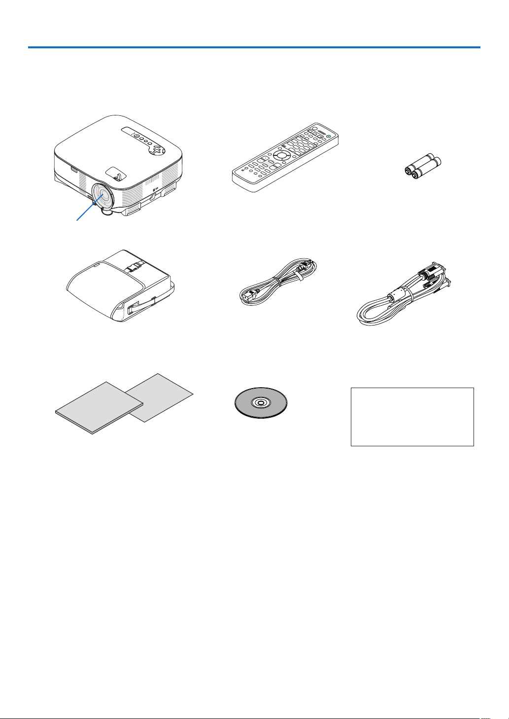
What’s in the Box?
Make sure your box contains everything listed. If any pieces are missing, contact your dealer.
Please save the original box and packing materials if you ever need to ship your Projector.
OF
F
COMPU
TE
R
VIDEO
AB
C
DEF
JKLGHI MNO
TUVPQRS WXYZ
.
@/
S-VIDEO
VIEWWRNETWORK
HDMI
PIP
MAGNIFY
VOLUME
PICTURE
LAMP MOD
E
ASPEC
T
AV-MUTE
3D REFORM
FREEZE
ID SET
LENS SHIFT
FOCUS/ZOOM
HELP
UP
DOWN
PAGE
CL
EAR
MENU
L-CLICKR-C
LICK
ENTER
EXI
T
1
123
4 56
7 8
0
9
2 3
COMPONENT
AUTO ADJ.
POWER
ID
ID
Lens cap
(24FU0141)
Remote control
(7N900811)
Batteries (AA x 2)
Power cable
(7N080204) US
(7N080011) EU
VGA signal cable
(7N520052)
CD-ROM
User’s manual
(7N951192)
For North America only
Registration card
Limited warranty
For Europe only
Guarantee policy
• Security sticker
• Important Infomation (7N8P8543)
• Quick Setup Guide (7N8P8531)
Projector
Soft Case
(24BS7851)

2
1. Introduction
❷
Introduction to the Projector
This section introduces you to the VT800 projector and describes key features and controls.
Congratulations on Your Purchase of the Projector
The VT800 is a sophisticated XGA projector that produces an enhanced display. With the VT800 you will be able
to project images up to 300" (measured diagonally). Enjoy crisp and sharp large screen display from your PC,
workstation or Macintosh computer, DVD player, VCR, satellite hookup, HDTV source, as well as images from your
USB storage device. The VT800 provides for enhanced security options to help deter projector theft and provides
for full projector control through the PC control port (D-Sub 9 Pin) and LAN support. With input and output exibil-
ity, long lamp life and a full function remote, the VT800 lets you enjoy larger than life viewing from a compact and
easy to setup and use projector.
Features you’ll enjoy :
• LCD projector with high resolution and high brightness
High resolution display - up to UXGA compatible, XGA native resolution.
• Direct Power Off & Auto Start
The projector has a feature called “Direct Power Off”. This feature allows the projector to be turned off (even
when projecting an image) using a power strip equipped with a switch and a breaker.
The AUTO POWER ON(AC) feature eliminates the need to always use the POWER button on the remote con-
trol or projector cabinet.
• Integrated RJ-45 connector for wired networking
An RJ-45 connector is equipped as standard features.
• Windows Vista standard functions Network Projector and Remote Desktop can be used
A Windows Vista-based computer can be operated using the projector over a network.
The projector supports the Network Projector function and the Remote Desktop function of Windows Vista.
• A variety of input ports and a comprehensive array of system control interfaces
This projector supports input signals on the following ports: HDMI, 15pin D-Sub, composite and S-video.
• Wall Color Correction
Built-in Wall Color Correction presets provide for adaptive color correction when projecting onto non-white
screen material (or a wall).
• Six picture preset modes for user adjustable picture and color settings
Each picture preset mode can be customized and memorized according to your preference.
• Silicon Optix HQV technology produces superior video processing
The technology produces superior video processing using pixel-based, motion-adaptive de-interlacing to re-
move undesirable motion artifacts typical of interlaced signals.
• Preventing unauthorized use of the projector
Enhanced smart security settings for password protection, cabinet control panel lock, and USB memory pro-
tection key to help prevent unauthorized access, adjustments and theft deterrence.

3
1. Introduction
About this user’s manual
The fastest way to get started is to take your time and do everything right the rst time. Take a few minutes now to
review the user’s manual. This may save you time later on. At the beginning of each section of the manual you’ll
nd an overview. If the section doesn’t apply, you can skip it.
4
1. Introduction
AC IN
VIDEO IN
AUDIO IN
USB
LAN
AUDIO IN
HDMI IN
AUD
IO IN
COMPUTER /
COMPON
ENT 2 IN
COMPUTER /
COMPON
ENT 1 IN
PC CONTROL
MONITOR OUT
AUDIO OUT
S-VIDEO
IN
AUDIO IN
L/MONO
L/MONO
R
R
USB
L
AMP
STATUS
SOURCE
AUTO ADJUST
3D REFORM
S
ELECT
USB
LAMP
STAT
US
SOURCE
AUTO AD
JUST
3D REFORM
SELECT
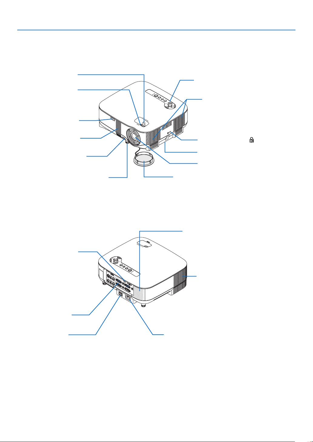
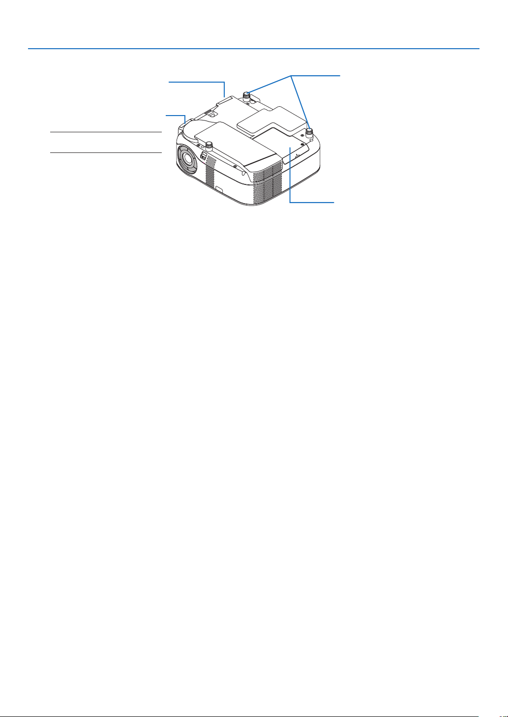
❸
Part Names of the Projector
Controls
(→ page 6)
Built-in Security Slot (
)*
Zoom Lever
(→ page 24)
Lens Cap
Remote Sensor
(→ page
9)
Focus Ring
(→ page 24)
Adjustable Tilt Foot Lever
(→ page
25)
* This security slot supports the MicroSaver® Security System. MicroSaver® is a registered trademark of Kens-
ington Microware Inc. The logo is trademarked and owned by Kensington Microware Inc.
Ventilation (inlet) / Filter
(→ page
114)
Adjustable Tilt Foot
(→ page 25)
Lens
Front/Top
Ventilation (inlet) / Filter
(→ page
114)
Speaker (5W monaural)
AC Input
Connect the supplied power cable’s three-pin plug here,
and plug the other end into an active wall outlet.
(→ page
19)
Main Power Switch
When you plug the supplied power cable into an ac-
tive wall outlet and turn on the Main Power switch, the
POWER indicator turns orange and the projector is in
standby mode.
(→ page 20)
Remote Sensor
(→ page 9)
Ventilation (outlet)
Heated air is exhausted from
here.
Rear
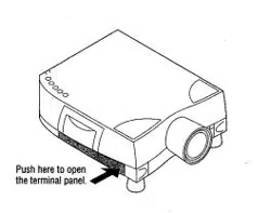
Terminal Panel
(→ page
7)
Security bar
6
1. Introduction
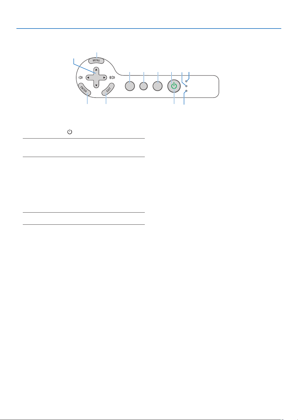
Top Features
1. POWER Button ( ) (→ page 20, 29)
NOTE: To turn on the projector, press and hold this button
for a minimum of two seconds. To turn off the projector,
press this button twice.
2. POWER Indicator (→ page
20, 29, 120)
3. STATUS Indicator (→ page 120)
4. LAMP Indicator (→ page
117, 120)
5. USB Indicator
Lights when a USB memory is inserted into the
USB port.
NOTE: The USB indicator will not light when non-USB stor-
age devices such as USB mouse devices are inserted.
6. SOURCE Button
7. AUTO ADJUST Button (→ page
28)
8. 3D REFORM Button (→ page 26, 36)
9. MENU Button
10. SELECT ▼▲◀ ▶ / Volume Buttons
11. ENTER Button
12. EXIT Button
USB
LAMP
STATUS
SOURCE
AUTO ADJUST
3D REFORM
SELECT
12
145
23
678
11
10
9
7
1. Introduction
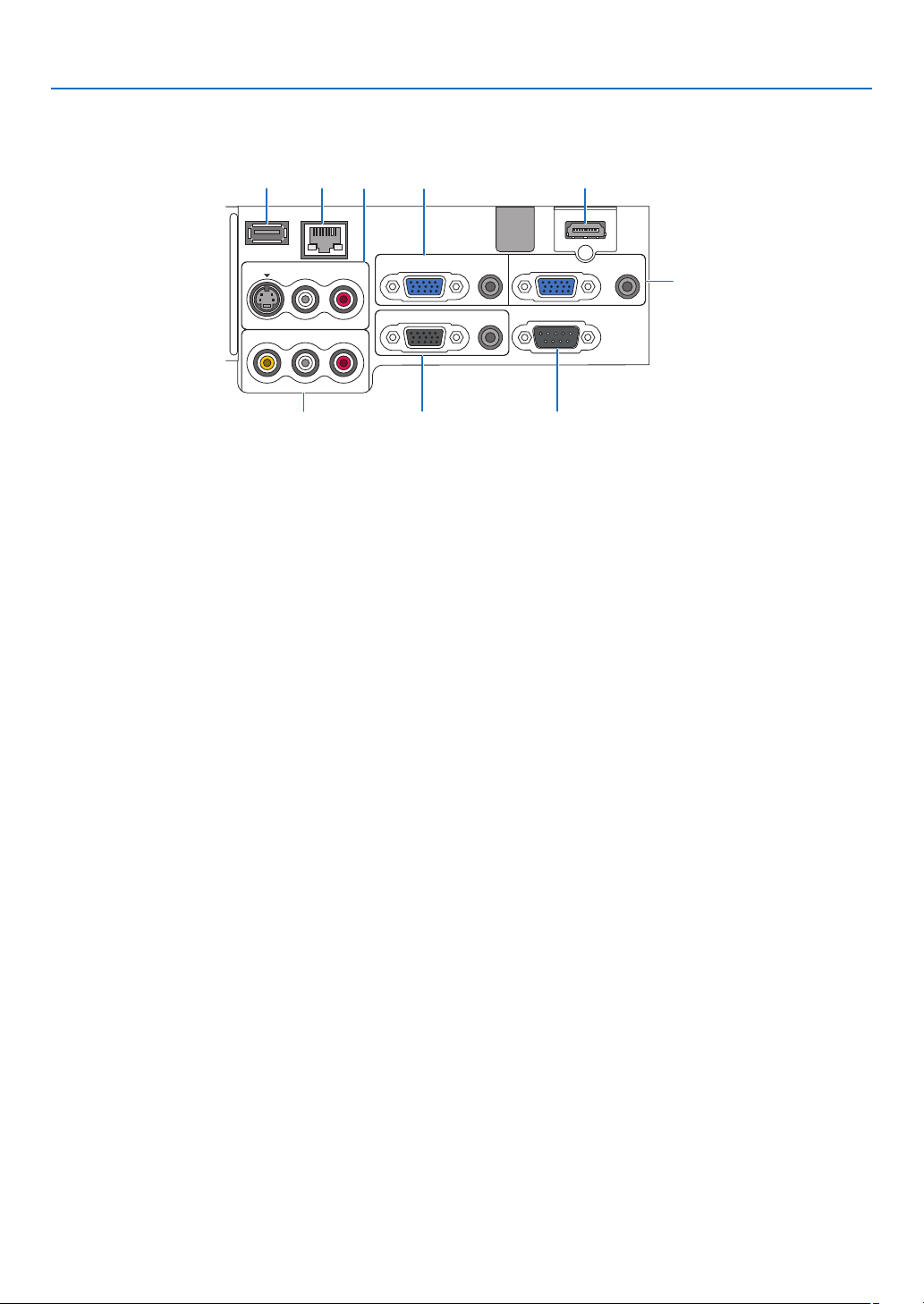
Terminal Panel Features
1. COMPUTER1 IN/COMPONENT 1 IN Connector
(Mini D-Sub 15 Pin)
(→ page
11, 13, 15)
AUDIO IN (Stereo Mini Jack)
(→ page 11, 13, 15)
2. COMPUTER2 IN/COMPONENT 2 IN Connector
(Mini D-Sub 15 Pin)
(→ page 11, 15)
AUDIO IN (Stereo Mini Jack)
(→ page 11)
3. HDMI IN (19 Pin HDMI Type A)
(→ page 12, 14)
4. S-VIDEO IN Connector (Mini DIN 4 Pin)
(→ page
16)
AUDIO L/MONO, R (RCA)
(→ page 16)
5. VIDEO IN Connector (RCA)
(→ page
16)
AUDIO L/MONO, R (RCA)
(→ page 16)
6. MONITOR OUT Connector (Mini D-Sub 15 Pin)
(→ page
13)
AUDIO OUT (Stereo Mini Jack)
(→ page
13)
7.
PC CONTROL Port (D-Sub 9 Pin)
(
→ p
age 130, 131)
Use this port to connect your PC or control system
to control your projector via a serial cable. This
enables you to control the projector using serial
communication protocol. A commercially available
RS232C cross cable is required to use this port.
You can also control the projector by using PC Con-
trol Utility 3.0 (downloadable from our website:http:
www.nec-pj.com). To do so you must rst have PC
Control Utility 3.0 installed on your PC. If you are
writing your own program, typical PC control codes
are on page 130.
8. USB Port (Type A)
(→ page 33)
9. LAN Port (RJ-45)
(→ page 18, 98)
The actual appearance of the terminal panel may differ slightly from that shown in the drawing, but this does not
affect the projector’s performance.
VIDEO IN
AUDIO IN
USB
LAN
AUDIO IN
HDMI IN
AUDIO IN
COMPUTER /
COMPONENT 2 IN
COMPUTER /
COMPONENT 1 IN
PC CONTROL
MONITOR OUT
AUDIO OUT
S-VIDEO IN
AUDIO IN
L/MONO
L/MONO
R
R
2
6 75
14
38 9
8
1. Introduction
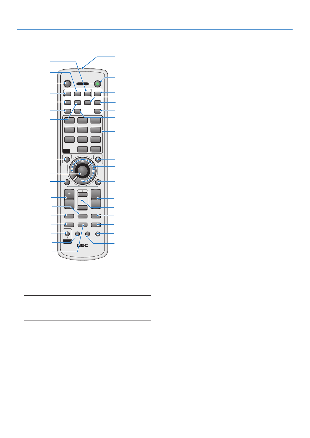
❹
Part Names of the Remote Control
1. Infrared Transmitter
2. POWER ON Button (→ page
20)
NOTE: To turn on the projector, press and hold the POWER
ON button for a minimum of two seconds.
3. POWER OFF Button (→ page
29)
NOTE: To turn off the projector, press the POWER OFF but-
ton twice.
4. COMPUTER1 Button (→ page
22)
5. COMPUTER2 Button (→ page 22)
6. COMPUTER 3 Button
(not available on this model)
7. AUTO ADJ. Button (→ page
28)
8. VIDEO Button (→ page
22)
9. S-VIDEO Button (→ page
22)
10. COMPONENT Button (→ page 22)
(not available on this model)
11. HDMI Button (→ page
22)
OFF ON
COMPUTER
VIDEO S-VIDEO
VIEWER
NETWORK
HDMI
PIP
MAGNIFYVOLUME
PICTURE
LAMP MODE
ASPECT
AV-MUTE
3D REFORM
FREEZE
ID SET
LENS SHIFT
RD 434E
FOCUS
/ZOOM
HELP
PAGE
MENU
L-CLICK
R-CLICK
EXIT
COMPONENT
AUTO ADJ.
1 32
4 65
7 98
0
CLEAR
ENTER
UP
DOWN
POWER
ID
ID
123
2
10
15
17
1
3
4
8
12
16
5
9
7
11
14
13
6
21
22
29
27
28
31
32
30
24
23
26
25
34
33
19
18
20
12. VIEWER Button (→ page 22, 62)
13. NETWORK Button (→ page
22)
14. PIP Button (→ page 40)
15. Numeric Keypad Button/CLEAR Button
(→ page 107)
16. MENU Button
17. SELECT ▲▼◀ ▶ Button
18. ENTER Button
19. EXIT Button
20. MOUSE R-CLICK Button (→ page
35)
21. MOUSE L-CLICK Button (→ page
35)
22. VOLUME +/– Buttons (→ page 28)
23. MAGNIFY +/– Buttons (→ page
31)
24. PAGE UP/DOWN Buttons (→ page
35)
25. FREEZE Button (→ page
31)
26. ASPECT Button (→ page
80)
27. PICTURE Button (→ page 75, 77)
28. AV-MUTE Button (→ page
31)
29. LAMP MODE Button (→ page
32)
30. 3D REFORM Button (→ page 26, 36)
31. ID SET Button (→ page
107)
32. LENS SHIFT Button
(not available on this model)
33. FOCUS/ZOOM Button
(not available on this model)
34. HELP Button (→ page
32)
9
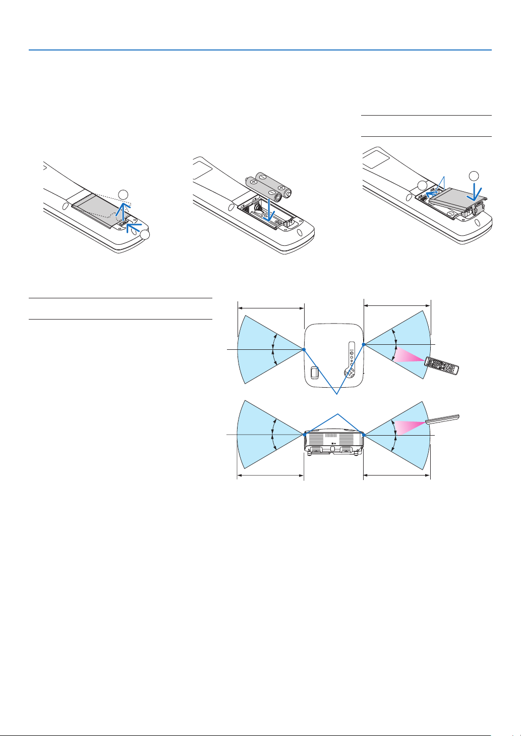
1. Introduction
Battery Installation
1
Press the catch and re-
move the battery cover.
2
Install new ones (AA). Ensure
that you have the batteries’ po-
larity (+/–) aligned correctly.
3
Slip the cover back over the bat-
teries until it snaps into place.
NOTE: Do not mix different types of
batteries or new and old batteries.
1
2
1
2
Remote Control Precautions
• Handle the remote control carefully.
• If the remote control gets wet, wipe it dry immediately.
• Avoid excessive heat and humidity.
• Do not heat, take apart, or throw batteries into re.
• If you will not be using the remote control for a long time, remove the batteries.
• Ensure that you have the batteries’ polarity (+/–) aligned correctly.
• Do not use new and old batteries together, or use different types of batteries together.
• Dispose of used batteries according to your local regulations.
Operating Range for Wireless Remote Control
30°
30°
30°
30°
30°
30°
30°
30°
Remote sensor on projector cabinet
7m/22 feet
7m/22 feet
Remote control
NOTE: Actual operating range may differ slightly
from that shown in the drawing.
TIP: You can determine which remote sensor on
the projector is enabled in wireless mode. The op-
tions are: front, rear or both. (→ page
106)
• The infrared signal operates by line-of-
sight up to a distance of about 22 feet/7
m and within a 60-degree angle of the
remote sensor on the projector cabinet.
• The projector will not respond if there are
objects between the remote control and
the sensor, or if strong light falls on the
sensor.
Weak batteries will also prevent the re-
mote control from properly operating the
projector.
7m/22 feet
7m/22 feet
Remote control
10
300"
240"
200"
150"
120"
100"
60"
80"
40"
1
3
2
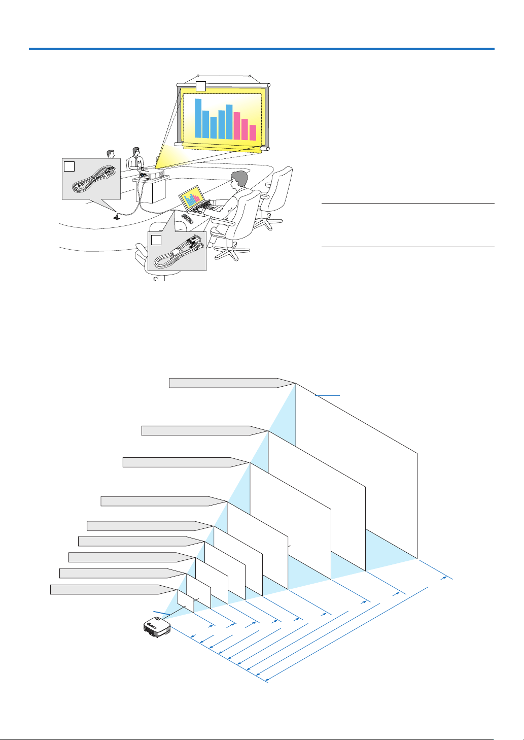
This section describes how to set up your projector and how to connect PCs, video and audio sources.
2. Installation and Connections
❶
Setting Up the Screen and the Projector
The further your projector is from the screen or wall, the larger the image. The minimum size the image can be
is 21 inches (0.53 m) measured diagonally when the projector is 29 inches (0.73 m) from the wall or screen. The
largest the image can be is 300 inches (7.62 m) when the projector is about 389 inches (9.9 m) from the wall or
screen. Use the drawing below as a guide.
Selecting a Location
Your projector is simple to set up and use.
But before you get started, you must rst:
z
Set up a screen and the projector.
x
Connect your computer or video
equip-ment to the projector. See pages
11, 13, 14, 15, 16, 17, 18.
c
Connect the supplied power cable.
See page
19.
NOTE: Ensure that the power cable and any oth-
er cables are disconnected before moving the
projector. When moving the projector or when
it is not in use, cover the lens with the lens cap.
TIP: The screen sizes above are intermediate values between tele (minimum display area) and wide (maximum display area). Im-
age size can be adjusted with the zoom adjustment up to a maximum of 10%.
For “Screen Size and Projection Distance”, see page
126.
Distance (Unit: m/inch)
1.3/
51.2
609.6 (W) x 457.2 (H) / 240 (W) x 180 (H)
2.0/
78.
7
2.6/
102.3
3.3
/
129.9
3.9
/
153.5
4.9
/
192.9
6.6
259.8
7.9/
310.9
9.8
385.7
487.7 (W) X 365.8 (H) / 192 (W) X 144 (H)
406.4 (W) X 304.8 (H) / 160 (W) X 120 (H)
304.8 (W) X 228.6 (H) / 120 (W) X 90 (H)
243.8 (W) X 182.9 (H) / 96 (W) X 72 (H)
203.2 (W) X 152.4 (H) / 80 (W) X 60 (H)
162.6 (W) X 122.0 (H) / 64 (W) X 48 (H)
121.9 (W) X 91.4 (H) / 48 (W) X 36 (H)
81.3 (W) X 61.0 (H) / 32 (W) X 24 (H)
Lens center
Screen Size
Screen Size (Unit: cm/inch)
11
2. Installation and Connections
WIRELESS
WIRELESS
USB
(
LAN
)
VIDEO IN
AUDIO IN
USB
LAN
AUDIO IN
HDMI IN
AUDIO IN
COMPUTER /
COMPONENT 2 IN
COMPUTER /
COMPONENT 1 IN
PC CONTROL
MONITOR OUT
AUDIO OUT
S-VIDEO IN
AUDIO IN
L/MONO
L/MONO
R
R
PHONE
COMPUTER/COMPONENT 2 IN
COMPUTER/COMPONENT 1 IN
PHONE
PHONE
AUDIO IN
AUDIO IN
❷
Making Connections
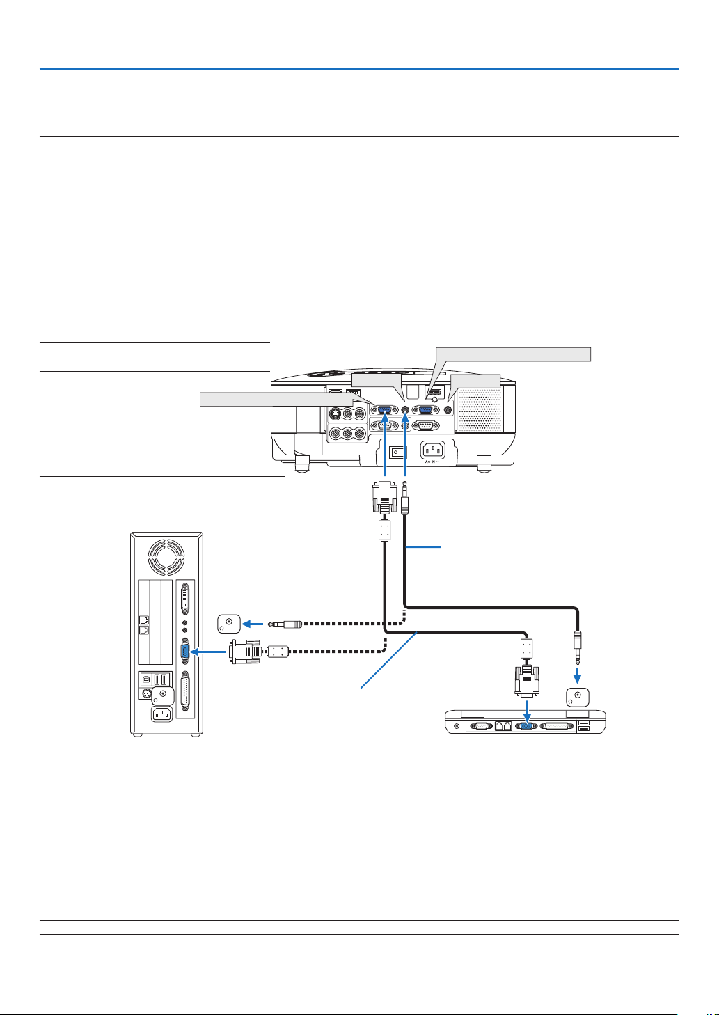
Connecting Your PC or Macintosh Computer
NOTE: When using with a notebook PC, be sure to connect the projector and notebook PC while the projector is in standby
mode and before turning on the power to the notebook PC.
In most cases the output signal from the notebook PC is not turned on unless connected to the projector before being powered up.
* If the screen goes blank while using your remote control, it may be the result of the computer’s screen-saver or power man-
agement software.
Enabling the computer’s external display
Displaying an image on the notebook PC’s screen does not necessarily mean it outputs a signal to the projector.
When using a PC compatible laptop, a combination of function keys will enable/disable the external display.
Usually, the combination of the ‘Fn” key along with one of the 12 function keys gets the external display to come
on or off. For example, NEC laptops use Fn + F3, while Dell laptops use Fn + F8 key combinations to toggle
through external display selections.
IBM VGA or Compatibles (Notebook
type) or Macintosh (Notebook type)
NOTE: The COMPUTER1 IN and COMPUTER2
IN connectors support Plug & Play (DDC2B).
NOTE: For older Macintosh, use a commercially
available pin adapter (not supplied) to connect to
your Mac’s video port.
• First turn off the computer and the projector before making connections.
• Turn down the volume on the computer before connecting an audio cable to the headphone jack of the com-
puter. After connecting the computer to the projector, you can adjust the sound level on the computer and the
projector to your preference.
• You are recommended to connect an audio cable to an audio out connector (mini jack type) if any.
NOTE: The VT800 is not compatible with video decoded outputs of either the NEC ISS-6020 or ISS-6010 switchers.
VGA signal cable (supplied)
To mini D-Sub 15-pin connector on the
projector. It is recommended that you
use a commercially available distribu-
tion amplifier if connecting a signal
cable longer than the one supplied.
Audio cable (not supplied)
12
2. Installation and Connections
NOTE: An image may not be displayed correctly when a Video or S-Video source is played back via a commercially available
scan converter.
This is because the projector will process a video signal as a computer signal at the default setting. In that case, do the following.
* When an image is displayed with the lower and upper black portion of the screen or a dark image is not displayed correctly:
Project an image to fi ll the screen and then press the AUTO ADJ button on the remote control or the AUTO ADJUST button on
the projector cabinet.
* When noise appears on the sides of the screen:
Use the Overscan feature to display the image correctly.
Be sure to change the Overscan to 0% before pressing the AUTO ADJ or AUTO ADJUST button, otherwise an image may be
displayed with its sides cut off.
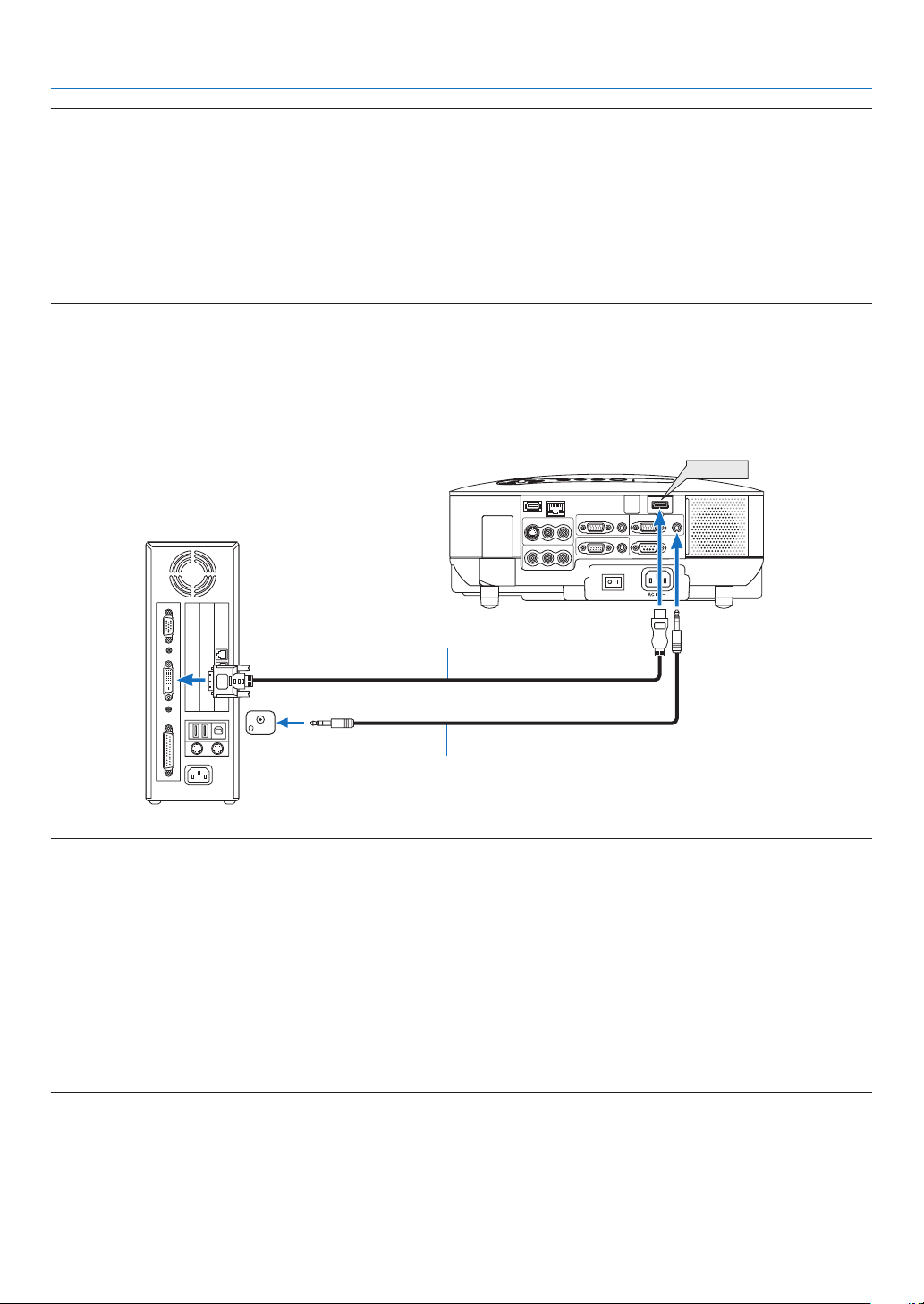
• If you have a PC with a DVI output, use a commercially available DVI-to-HDMI cable to connect the PC to the
HDMI IN connector of the projector. Only the digital signal is available. Connect the AUDIO output of the PC
to the COMPUTER/COMPONENT 2 AUDIO IN stereo mini jack, and in the menu select [HDMI SETTINGS] →
[AUDIO SELECT] → [COMPUTER2]. (→ page
109)
WIRELESS
WIRELESS
VIDEO IN
AUDIO IN
USB
LAN
AUDIO IN
HDMI IN
AUDIO IN
COMPUTER /
COMPONENT 2 IN
COMPUTER /
COMPONENT 1 IN
PC CONTROL
MONITOR OUT
AUDIO OUT
S-VIDEO IN
AUDIO IN
L/MONO
L/MONO
R
R
HDMI IN
PHONE
DVI to HDMI cable (not supplied)
Audio cable (not supplied)
NOTE: When Viewing a DVI Digital Signal
• Use a DVI-to-HDMI cable compliant with DDWG (Digital Display Working Group) DVI (Digital Visual Interface) revision 1.0
standard. The cable should be within 197"/5 m long.
• Turn off the projector and the PC before connecting the DVI-to-HDMI cable.
• To project a DVI digital signal: Connect the cables, turn the projector on, then select the HDMI input. Finally, turn on your PC.
Failure to do so may not activate the digital output of the graphics card resulting in no picture being displayed. Should this
happen, restart your PC.
• Some graphics cards have both analog RGB (15-pin D-Sub) and DVI (or DFP) outputs. Use of the 15-pin D-Sub connector may
result in no picture being displayed from the digital output of the graphics card.
• Do not disconnect the DVI-to-HDMI cable while the projector is running. If the signal cable has been disconnected and then
reconnected, an image may not be correctly displayed. Should this happen, restart your PC.
• The HDMI IN connector accepts VGA (640 x 480), SVGA (800 x 600), XGA (1024 x 768), 1152 x 864, WXGA (1280 x 768, 1280
x 800), WXGA+ (1440 x 900), SXGA (1280 x 1024 @ 60Hz), and SXGA+ (1400 x 1050 @ 60Hz).
13
2. Installation and Connections
AUDIO
IN
WIRELESS
WIRELESS
VIDEO IN
AUDIO IN
USB
LAN
AUDIO IN
HDMI IN
AUDIO IN
COMPUTER /
COMPONENT 2 IN
COMPUTER /
COMPONENT 1 IN
PC CONTROL
MONITOR OUT
AUDIO OUT
S-VIDEO IN
AUDIO IN
L/MONO
L/MONO
R
R
PHONE
AUDIO OUT
MONITOR OUT
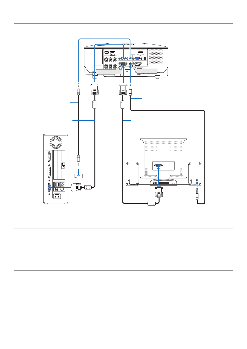
Connecting an External Monitor
You can connect a separate, external monitor to your projector to simultaneously view on a monitor the RGB ana-
log or component image you’re projecting.
NOTE:
• Daisy chain connection is not possible.
• The MONITOR OUT connector will not output video and sound (Digital signal) via the HDMI IN connector.
• When audio equipment is connected, the projector speaker is disabled.
• When [NORMAL] is selected from [STANDBY MODE], the MONITOR OUT connector outputs the last displayed video signal
and the AUDIO OUT jack outputs the last audio signal. The sound level remains the same as the last one.
• Selecting [POWER-SAVING] in [STANDBY MODE] stops outputting a video signal from the MONITOR OUT connector during
standby mode. This causes the AUDIO OUT jack to stop outputting sound.
VGA signal cable (supplied)
Audio cable (not supplied)
Audio cable (not supplied)
VGA signal cable (not supplied)
14
2. Installation and Connections
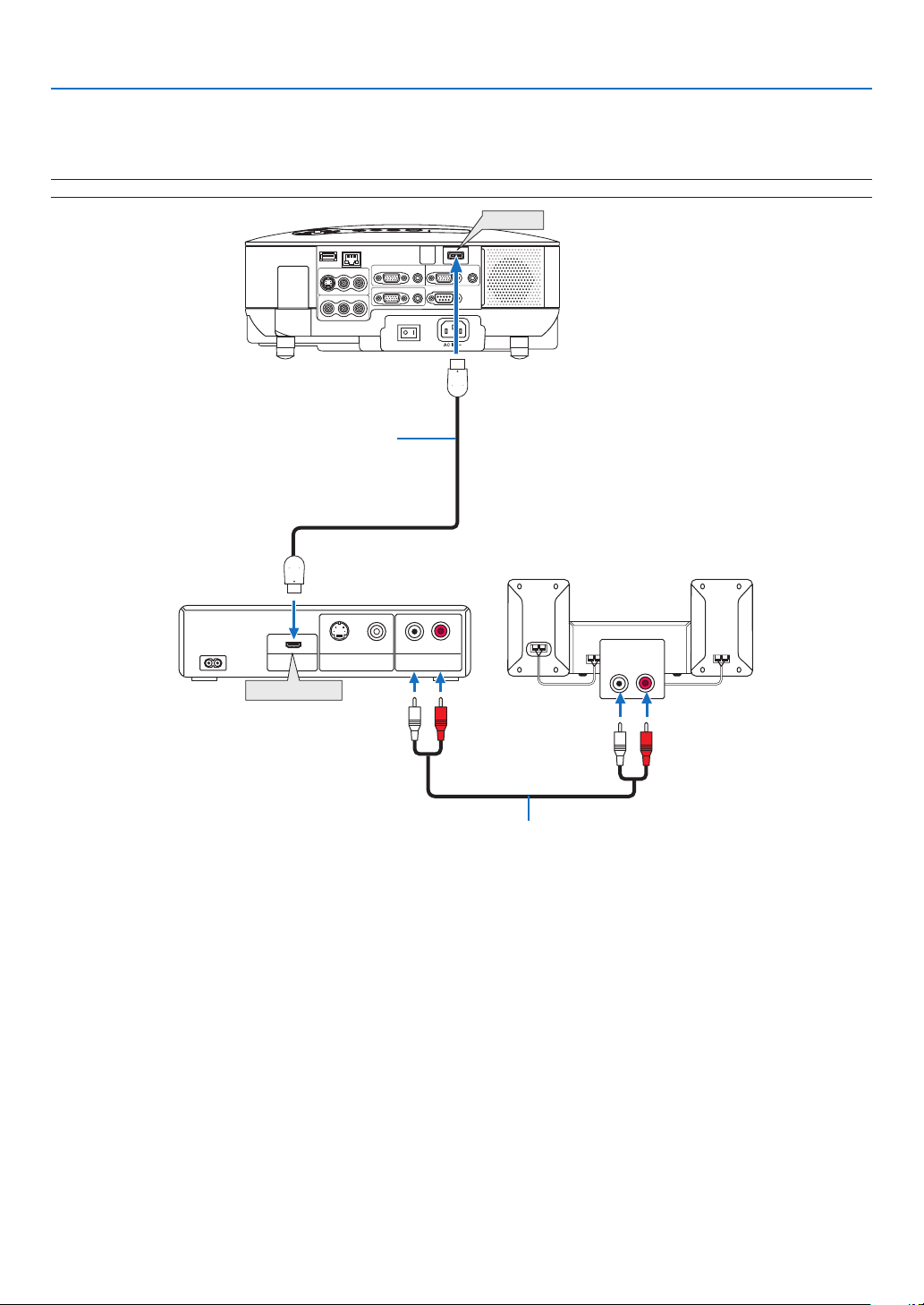
Connecting Your HDMI Compatible Equipment
You can connect the HDMI output of your DVD player, hard disk player, or notebook type PC to the HDMI IN con-
nector of your projector.
NOTE: The HDMI IN connector supports Plug & Play (DDC2B).
AUDIO IN
LR
AUDIO OUT
LR
VIDEO OUT
HDMI OUT
S-VIDEO VIDEO
WIRELESS
WIRELESS
VIDEO IN
AUDIO IN
USB
LAN
AUDIO IN
HDMI IN
AUDIO IN
COMPUTER /
COMPONENT 2 IN
COMPUTER /
COMPONENT 1 IN
PC CONTROL
MONITOR OUT
AUDIO OUT
S-VIDEO IN
AUDIO IN
L/MONO
L/MONO
R
R
HDMI Output
HDMI
HDMI
HDMI IN
Audio cable (not supplied)
HDMI cable (not supplied)
Use High Speed HDMI™ Cable.
TIP: For users of audio video equipment with an HDMI connector:
Select “Enhanced”rather than“Normal” if HDMI output is switchable between“Enhanced”and“Normal”.
This will provide improved image contrast and more detailed dark areas.
For more information on settings, refer to the instruction manual of the audio video equipment to be connected.
• When connecting the HDMI IN connector of the projector to the DVD player, the projector’s video level can be
made settings in accordance with the DVD player’s video level. In the menu select [HDMI SETTINGS] → [VIDEO
LEVEL] and make necessary settings.
• Acceptable signals are 480p, 576p, 720p, 1080i, and 1080p.
• The HDMI IN connector supports Deep Color (480p, 576p, 720p, 1080i).
The supported audio format is Linear PCM (32/44.1/48kHz and 16/20/24 bit).
• If the HDMI input sound cannot be heard, in the menu select [HDMI SETTINGS] → [AUDIO SELECT] → [HDMI].
What is HDCP/HDCP technology?
HDCP is an acronym for High-bandwidth Digital Content Protection. High bandwidth Digital Content Protection
(HDCP) is a system for preventing illegal copying of video data sent over a Digital Visual Interface (DVI).
If you are unable to view material via the HDMI input, this does not necessarily mean the projector is not function-
ing properly. With the implementation of HDCP, there may be cases in which certain content is protected with
HDCP and might not be displayed due to the decision/intention of the HDCP community (Digital Content Protec-
tion, LLC).
15
2. Installation and Connections
AUDIO IN
LR
AUDIO OUT
L R
Component
YCbCr
WIRELESS
WIRELESS
VIDEO IN
AUDIO IN
USB
LAN
AUDIO IN
HDMI IN
AUDIO IN
COMPUTER /
COMPONENT 2 IN
COMPUTER /
COMPONENT 1 IN
PC CONTROL
MONITOR OUT
AUDIO OUT
S-VIDEO IN
AUDIO IN
L/MONO
L/MONO
R
R
COMPUTER/COMPONENT 1 IN
COMPUTER/COMPONENT 2 IN
AUDIO IN
AUDIO IN
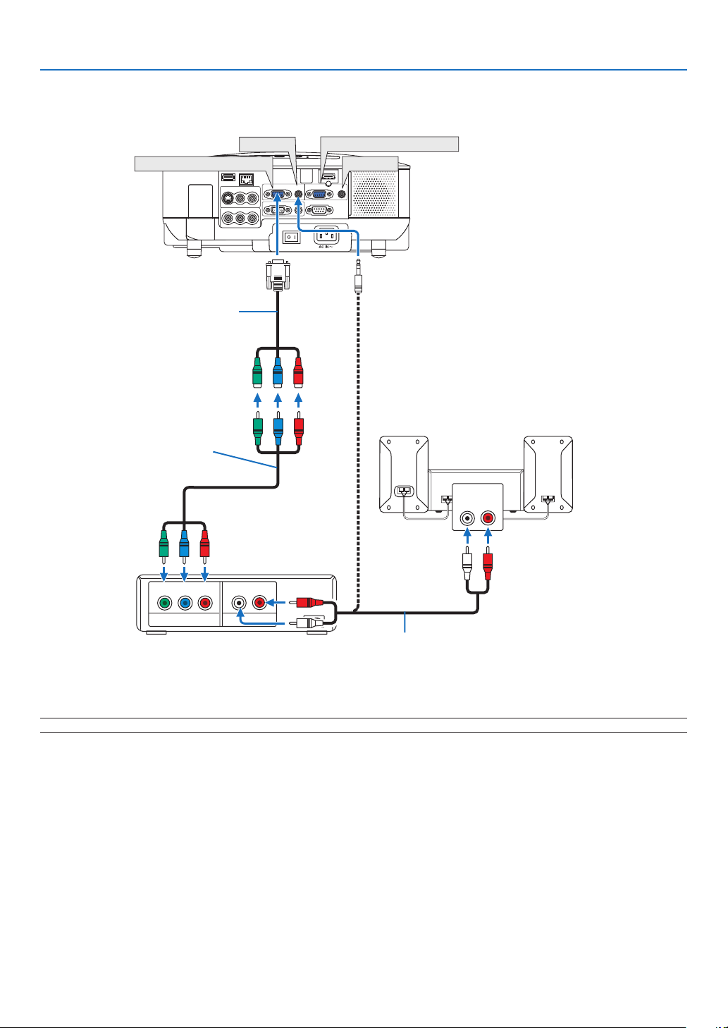
Connecting Your DVD Player with Component Output
DVD player
Audio Equipment
Audio cable (not supplied)
Component video RCAx3
cable (not supplied)
TIP: A component signal will be automatically displayed. If not, from the menu, select [SETUP] → [OPTIONS] → [SIGNAL SE-
LECT] → [COMPUTER1 (or 2)] → [COMPONENT].
NOTE: Refer to your DVD player’s owner’s manual for more information about your DVD player’s video output requirements.
Optional 15-pin - to - RCA (female) x 3
cable (ADP-CV1E)
16
2. Installation and Connections
AUDIO IN
LR
AUDIO OUT
L R
VIDEO OUT
S-VIDEO VIDEO
WIRELESS
WIRELESS
VIDEO IN
AUDIO IN
USB
LAN
AUDIO IN
HDMI IN
AUDIO IN
COMPUTER /
COMPONENT 2 IN
COMPUTER /
COMPONENT 1 IN
PC CONTROL
MONITOR OUT
AUDIO OUT
S-VIDEO IN
AUDIO IN
L/MONO
L/MONO
R
R
S-VIDEO IN
VIDEO IN
AUDIO IN
AUDIO IN
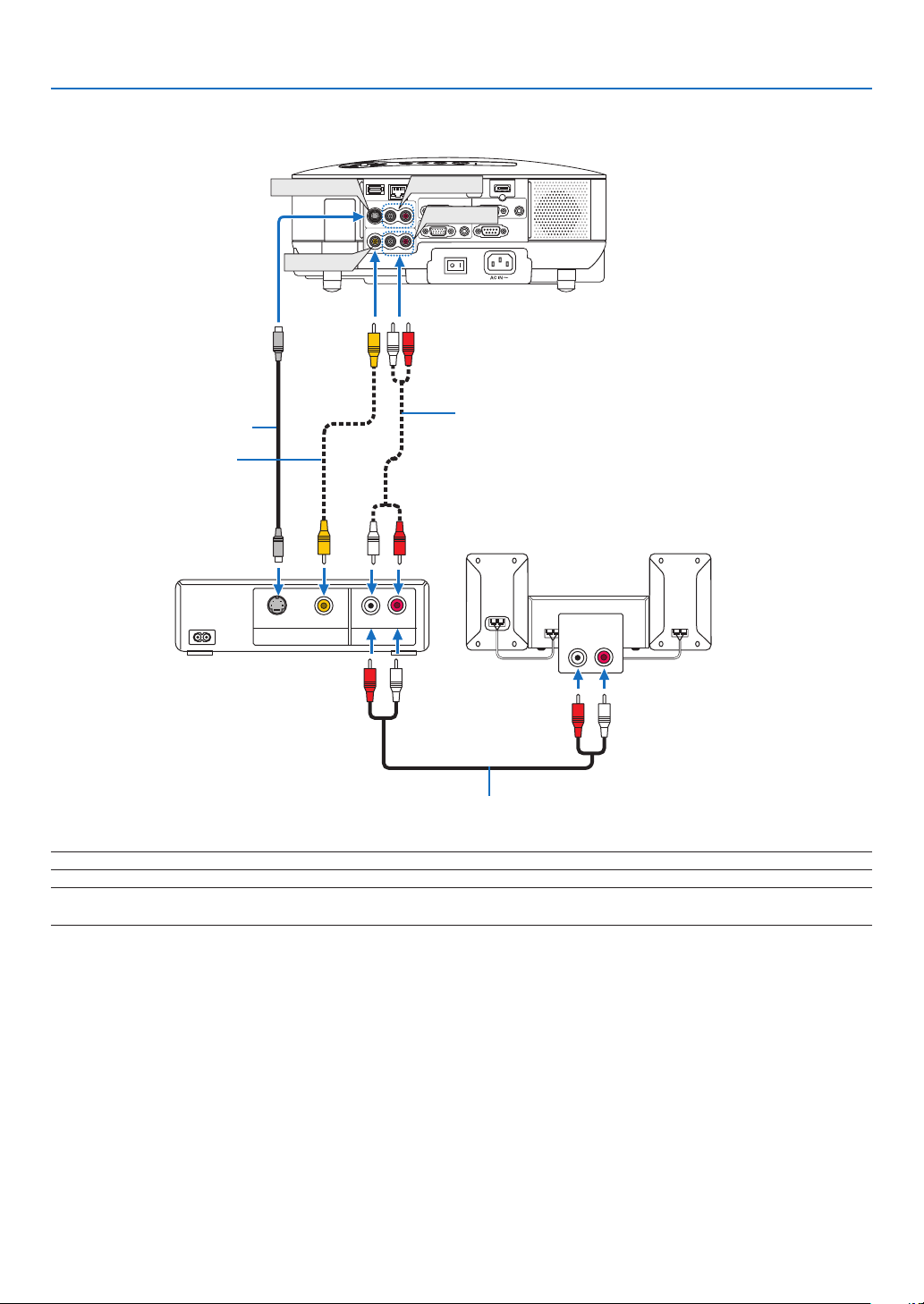
Connecting Your VCR
S-Video cable (not supplied)
Video cable (not supplied)
VCR
Audio equipment
Audio cable (not supplied)
NOTE: Refer to your VCR owner’s manual for more information about your equipment’s video output requirements.
NOTE: An image may not be displayed correctly when a Video or S-Video source is played back in fast-forward or fast-rewind via
a scan converter.
Audio cable (not supplied)

17
2. Installation and Connections
Connecting to a Network
The VT800 comes standard with a LAN port (RJ-45) which provides a LAN connection using a LAN cable. To use
a LAN connection, you are required to assign an IP address to the projector. For setting the NETWORK, see page
95. (From the menu, select [SETUP] → [INSTALLATION(2)] → [NETWORK SETTINGS])
With the LAN connection, two features are available: Projector control and Picture transmission.
Projector control feature
With the wired LAN connection, you can control (power on/off, input select, etc.) and receive information from the
projector over the network using a computer. The following three methods are available:
* Using the HTTP Server feature on the projector. (→ page 49)
* Using PC Control Utility 3.0*
1
* Using Image Express Utility 2.0*
1
Picture transmission feature (Using WindowsVista)
A Windows Vista-based computer can be operated using the projector over a network. The projector supports the
Network Projector function and the Remote Desktop function of Windows Vista. (→ page
52, 56)
Picture transmission feature (Using User Supportware)
With the wired LAN connection, you can send images and slides from a personal computer to the projector which
then can be projected on the screen. The following two methods are available:
* Using Image Express Utility 2.0*
1
* Using Ulead Photo Explorer 8.0*
2
With the USB mouse connected to the projector, you can also operate the desktop screen on your Windows PC
connected to the LAN.
* Using Desktop Control Utility 1.0*
1
• For the procedure to connect Windows Vista with the network (wired LAN), refer to the manual of Windows
Vista.
NOTE:
*
1
Software is downloadable from http://www.nec-pj.com
*
2
Ulead Photo Explorer 8.0 is included on the optional User Supportware 5 CD-ROM.
18
2. Installation and Connections
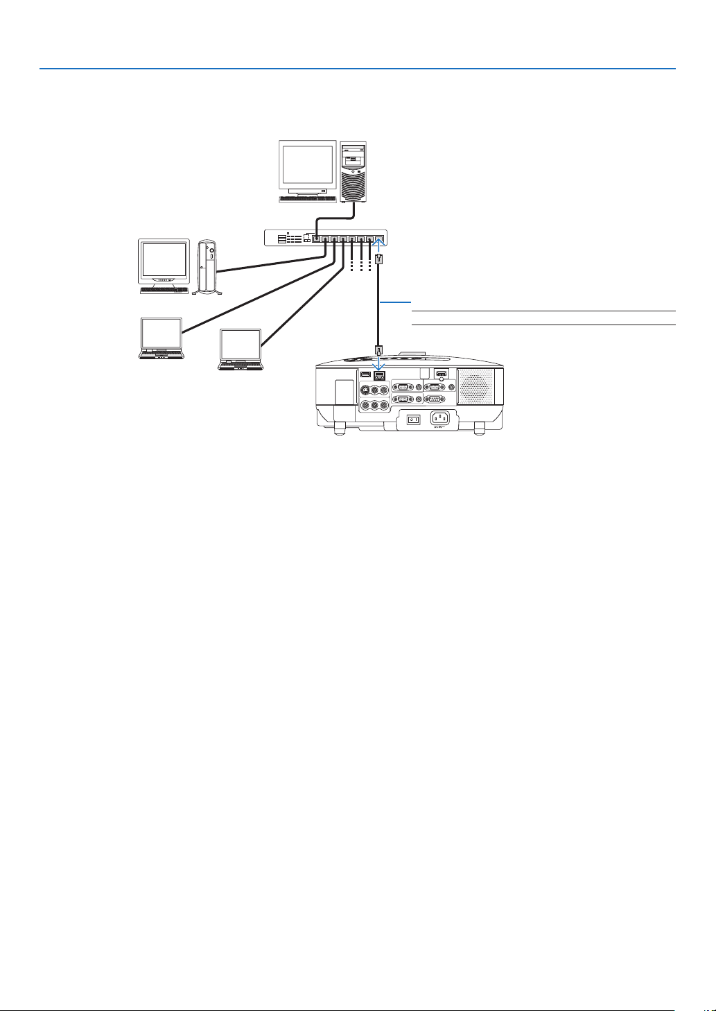
Example of LAN connection
Example of wired LAN connection
LAN
VIDEO IN
AUDIO IN
USB
LAN
AUDIO IN
HDMI IN
AUDIO IN
COMPUTER /
COMPONENT 2 IN
COMPUTER /
COMPONENT 1 IN
PC CONTROL
MONITOR OUT
AUDIO OUT
S-VIDEO IN
AUDIO IN
L/MONO
L/MONO
R
R
Server
Hub
LAN cable (not supplied)
NOTE: Use a Category 5 or higher LAN cable.
19
2. Installation and Connections
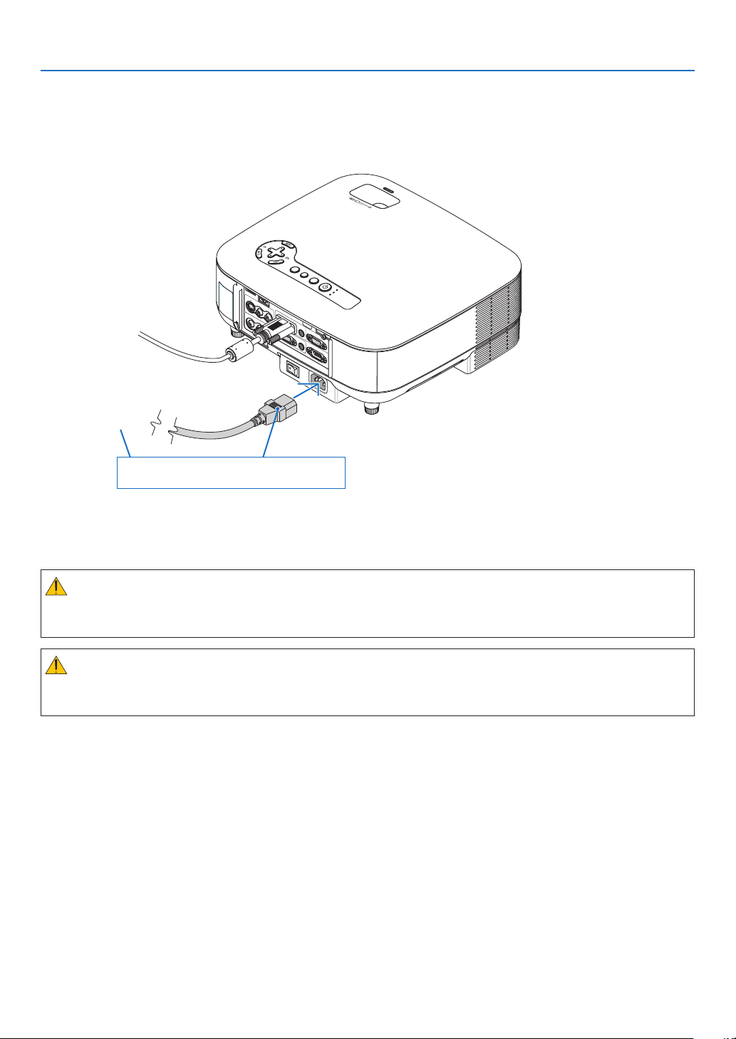
Connecting the Supplied Power Cable
Connect the supplied power cable to the projector.
First connect the supplied power cable’s three-pin plug to the AC IN of the projector, and then connect the other
plug of the supplied power cable in the wall outlet.
VIDEO IN
AUDIO IN
USB
LAN
AUD
IO IN
HDMI IN
AUDIO IN
COMPUTER /
COMPONEN
T 2 I
N
COMPUTER /
COMPONEN
T 1 IN
PC CONTROL
MONITOR OU
T
AUDIO OU
T
S-VIDEO
I
N
AUDIO IN
L/MONO
L/MONO
R
R
AC IN
USB
LAMP
STATUS
SOURCE
AUTO ADJUST
3D REFORM
SELECT
TIP: To turn off the AC power supply when the projector is powered on, use a power strip equipped with a switch and a breaker.
CAUTION:
Do not try to touch the ventilation outlet on the left front (when seen from the front) as it can become heated
while the projector is turned on and immediately after the projector is turned off.
CAUTION:
Do not unplug the power cable from the wall outlet or projector when the projector is powered on. Doing so can
cause damage to the AC IN connector of the projector and (or) the prong plug of the power cable.
About Direct Power Off
The projector has a feature called “Direct Power Off”. This feature allows the projector to be turned off (even when
projecting an image) using a power strip equipped with a switch and a breaker.
To wall outlet
Make sure that the prongs are fully insert-
ed into both the AC IN and the wall outlet.
20
COMPUTER
VIDEO S-VIDEO
VIEWER
NETWORK
HDMI
PIP
COMPONENT
AUTO ADJ.
1 32
4 65
7 98
POWER
123
OFF ON
USB
LAMP
STATUS
SOURCE
AUTO ADJUST
R
EFORM
3. Projecting an Image (Basic Operation)
This section describes how to turn on the projector and to project a picture onto the screen.
❶
Turning on the Projector
NOTE:
• The projector has two power switches: a main power switch and a POWER button (POWER ON and OFF on the remote con-
trol).
• When plugging in or unplugging the supplied power cable, make sure that the main power switch is pushed to the off (○)
position. Failure to do so may cause damage to the projector.
• The projector has a feature to prevent itself from being used by unauthorized individuals. To use this feature, register a key-
word. (→ page
41)
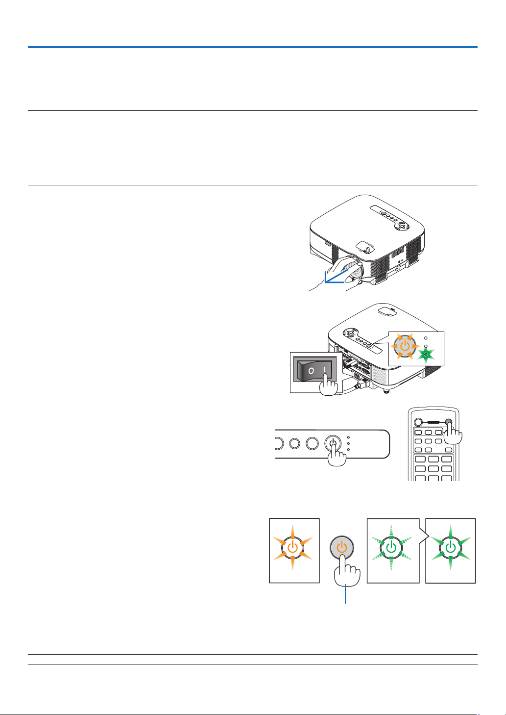
1. Remove the lens cap.
• Do not try to remove the lens cap by pulling on the
string. Doing so can cause damage.
2. To turn on the main power to the projector, press the
Main Power switch to the on position ( I ).
• The projector will go into standby mode. When in
standby mode, the POWER indicator will light orange
and the STATUS indicator will light green.
3. After making sure that the projector is in standby
mode, press the POWER or POWER (ON) button for
a minimum of 2 seconds when the STATUS indicator
goes off and the POWER indicator starts blinking.
When the POWER indicator turns a steady green,
and the projector is ready to use.
• After you turn on your projector, ensure that the com-
puter or video source is turned on and that your lens
cap is removed.
NOTE: When no signal is available, a blue, black or logo screen is displayed.
Standby Blinking Power On
Steady orange
light
Blinking green
light
Steady green
light
(→ page
120)
Press this button for a
minimum of 2 seconds.
VIDEO IN
AUDIO
IN
USB
LAN
AUDIO IN
HDMI IN
AUDIO IN
COMPUTER /
COMPONENT 2 IN
COMPUTER /
COMPONENT 1 IN
PC CONTROL
MONITOR OUT
AUDIO OUT
S-VIDEO IN
AUDIO IN
L/MONO
L/MONO
R
R
AC IN
USB
LAMP
STATUS
SOURCE
AUTO ADJUST
3D REF
OR
M
SELECT
USB
LAMP
STATUS
USB
LAMP
STATUS
SOURCE
AUTO ADJUST
3D REFORM
SELECT
21
3. Projecting an Image (Basic Operation)
ENTER
MAGNIFYVOLUME
PICTURE
LAMP MODE
ASPECT
AV-MUTE
3D REFORM
FREEZE
ID SET
LENS SHIFT
FOCUS
/ZOOM
HELP
PAGE
MENU
L-CLICK
R-CLICK
EXIT
0
CLEAR
UP
DOWN
ID
ID
MAGNIFYVOLUME
PICTURE
LAMP MODE
ASPECT
AV-MUTE
3D REFORM
FREEZE
ID SET
LENS SHIFT
FOCUS
/ZOOM
HELP
PAGE
MENU
L-CLICK
R-CLICK
EXIT
ENTER
UP
DOWN
ID
SO
AUTO ADJUST
3D REFORM
SELECT
SO
AUTO ADJUST
3D REFORM
SELECT
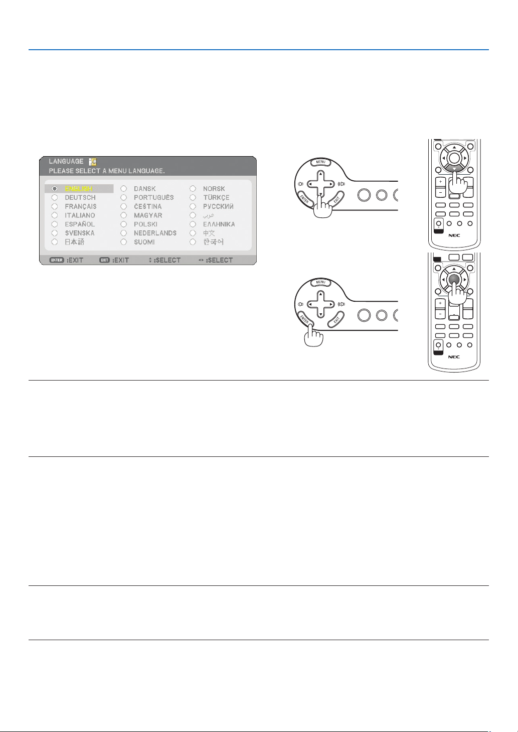
Note on Startup screen (Menu Language Select screen)
When you rst turn on the projector, you will get the Startup menu. This menu gives you the opportunity to select
one of the 21 menu languages.
To select a menu language, follow these steps:
1. Use the SELECT ▼ button to select one of the 21 lan-
guages for the menu.
2. Press the ENTER button to execute the selection.
After this has been done, you can proceed to the menu
operation.
If you want, you can select the menu language later. (→
[LANGUAGE] on page 91)
NOTE:
• The projector cannot be turned off for 60 seconds after the lamp is turned on and while the POWER indicator is blinking
green.
• If you turn on the projector immediately after the lamp is turned off or when the ambient temperature is high, the cooling fans
will run for a moment and then you will get an image on the screen.
• Immediately after turning on the projector, screen fl icker may occur. This is normal. Wait 3 to 5 minutes until the lamp light-
ing is stabilized.
• When the Lamp mode is set to Eco, the Lamp indicator will light green.
• If one of the following things happens, the projector will not turn on.
- If the internal temperature of the projector is too high, the projector detects abnormal high temperature. In
this condition the projector will not turn on to protect the internal system. If this happens, wait for the projec-
tor’s internal components to cool down.
- When the lamp reaches its end of usable life, the projector will not turn on. If this happens, replace the lamp.
(→ page
117)
- If the lamp fails to light, and if the STATUS indicator ashes on and off in a cycle of six times, wait a full min-
ute and then turn on the power.
NOTE: Turning the Main Power Switch Off then Back On
Allow a minimum of 5 seconds between turning off the main power switch and turning it back on again.
The same will be applied when a power strip equipped with a switch and a breaker is used.
Failing to do so could result in no power to the projector. (There will be no stand-by LED)
Should this happen, unplug the power cable and plug it in again. Turn on the main power switch.
22
3. Projecting an Image (Basic Operation)
USB
LAMP
STATUS
SOURCE
AUTO ADJUST
R
EFORM
❷
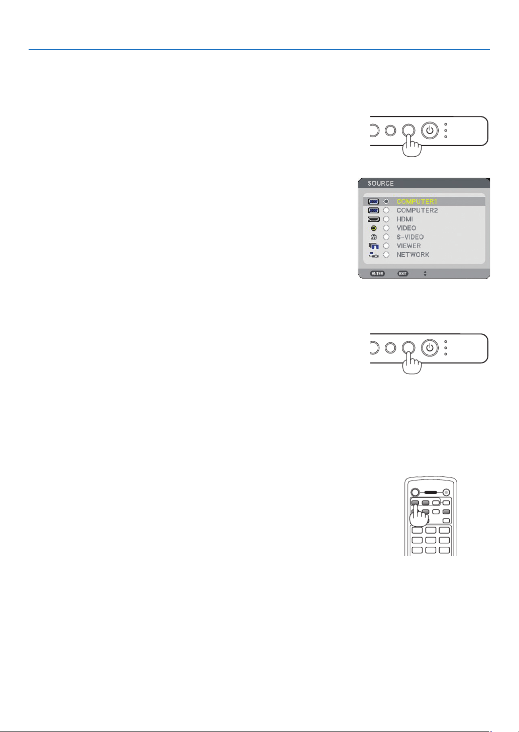
Selecting a Source
Selecting the computer or video source
Detecting the Signal Automatically
Press and hold the SOURCE button for a minimum of 1 second, the projector
will search for the next available input source. Each time you press and hold
the SOURCE button for a minimum of 1 second, the input source will change
as follows:
COMPUTER1 → COMPUTER2 → HDMI → VIDEO → S-VIDEO → VIEWER →
COMPUTER1 → ...
If no input signal is present, the input will be skipped. When the input source
you wish to project is displayed, release the button.
Using the Remote Control
Press any one of the COMPUTER1/2, HDMI, VIDEO, S-VIDEO, VIEWER or
NETWORK buttons.
Selecting from Source List
Press and quickly release the SOURCE button on the projector cabinet to
display the Source list. Each time the SOURCE button is pressed, the input
source will change as follows: “COMPUTER1/2”, “HDMI”, “VIDEO” (VCR), “S-
VIDEO”, “VIEWER” (slides on a USB memory) or “NETWORK” (LAN port
[RJ-45]).
To display the selected source, press the ENTER button.
USB
LAMP
STATUS
SOURCE
AUTO ADJUST
R
EFORM
VIEWER
NETWORK
HDMI
312
OFF ON
COMPUTER
VIDEO S-VIDEO
VIEWER
NETWORK
HDMI
PIP
COMPONENT
AUTO ADJ.
1 32
4 65
7 98
POWER
23
3. Projecting an Image (Basic Operation)
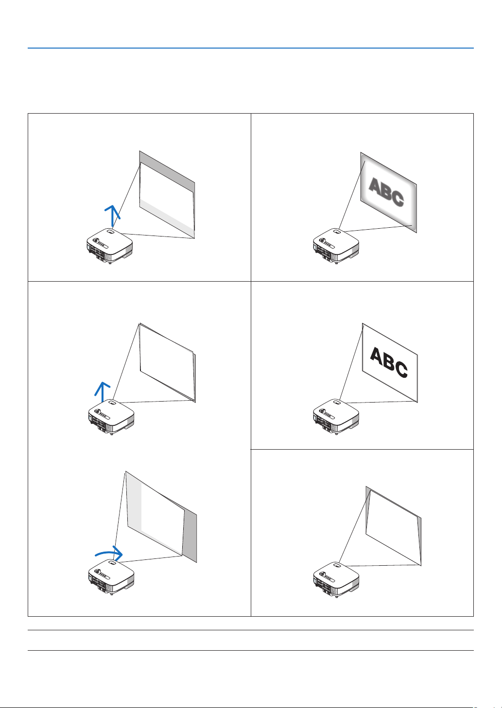
Use the adjustable tilt foot lever, the zoom lever or the focus ring to adjust the picture size and position.
❸
Adjusting the Picture Size and Position
NOTE*: See “
❹
Correcting Keystone Distortion” on page
26 for Keystone.
* In the above drawings, cables are omitted for clarity.
Adjusting the focus
[Focus ring]
Adjusting the throw angle (the height of an image)
[Tilt foot]
Finely adjusting the size of an image
[Zoom lever]
Adjusting the left and right tilt of an image
[Rear foot]
Adjusting the keystone correction
[Keystone] *
(→ page 25)
24
3. Projecting an Image (Basic Operation)
Adjusting the focus (Focus ring)
• Rotate the focus ring to make focus adjustment.
VIDEO
IN
AUDIO IN
USB
LAN
AUDIO IN
HDMI IN
AUDIO IN
COMPUTER /
COMPONENT 2 IN
COMPUTER /
COMPONENT 1 IN
PC CONTRO
L
MONITOR OUT
AUDIO OU
T
S-VID
EO I
N
AUDIO IN
L/MONO
L/MONO
R
R
AC I
N
USB
LAMP
STATUS
SOURCE
AUTO ADJUST
3D REFORM
SELECT
Finely adjusting the size of an image (Zoom lever)
• Rotate the zoom lever to adjust the image size on the screen.
VIDEO IN
AUDIO IN
USB
LAN
AUDIO IN
HDMI IN
AUDIO IN
COMPUTER /
COMPONENT 2 IN
COMPUTER /
COMPONENT 1 IN
PC CONTROL
MONITOR OUT
AUDIO OU
T
S-VIDEO IN
AUDIO IN
L/MONO
L/MONO
R
R
AC I
N
USB
LAMP
STATUS
SOURCE
AUTO
ADJUST
3D REFORM
SELECT
25
3. Projecting an Image (Basic Operation)
A
UT
3D
REFORM
1
2
Adjusting the Tilt Foot
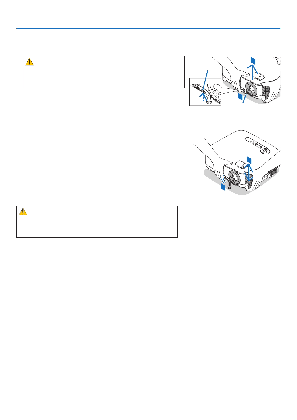
1. Lift the front edge of the projector.
CAUTION:
Do not try to touch the ventilation outlet during Tilt Foot adjustment
as it can become heated while the projector is turned on and during
its cool down period after it is turned off.
2.
Push up the Adjustable Tilt Foot Lever on the front of the projector
to extend the adjustable tilt feet (maximum height).
3. Lower the front of the projector to the desired height.
4.
Release the Adjustable Tilt Foot lever to lock the Adjustable tilt foot.
There is approximately 10 degrees (up) of adjustment for the front of
the projector.
TIP: For operating the [KEYSTONE] screen, see “❹ Correcting Keystone Dis-
tortion” on page
26.
NOTE: Your “Keystone” correction data can be reset by pressing and holding
the 3D REFORM button for a minimum of 2 seconds.
CAUTION:
Do not use the tilt-foot for purposes other than originally intended.
Misuses such as using the tilt foot to carry or hang (from the wall or
ceiling) the projector can cause damage to the projector.
The rear foot height can be adjusted up to 0.5 inch/13 mm.
Rotate the rear foot to the desired height in order to square the image on
the projection surface, but the vertical distance from the bottom to the
desk or oor should be 0.5 inch /13mm to make the projector horizontal
on the at surface.
Adjustable Tilt
Foot Lever
USB
LAMP
STATUS
SOURCE
AUT
O ADJUST
3
D REFORM
SELECT
4
3
Adjustable Tilt Foot
26
3. Projecting an Image (Basic Operation)
❹
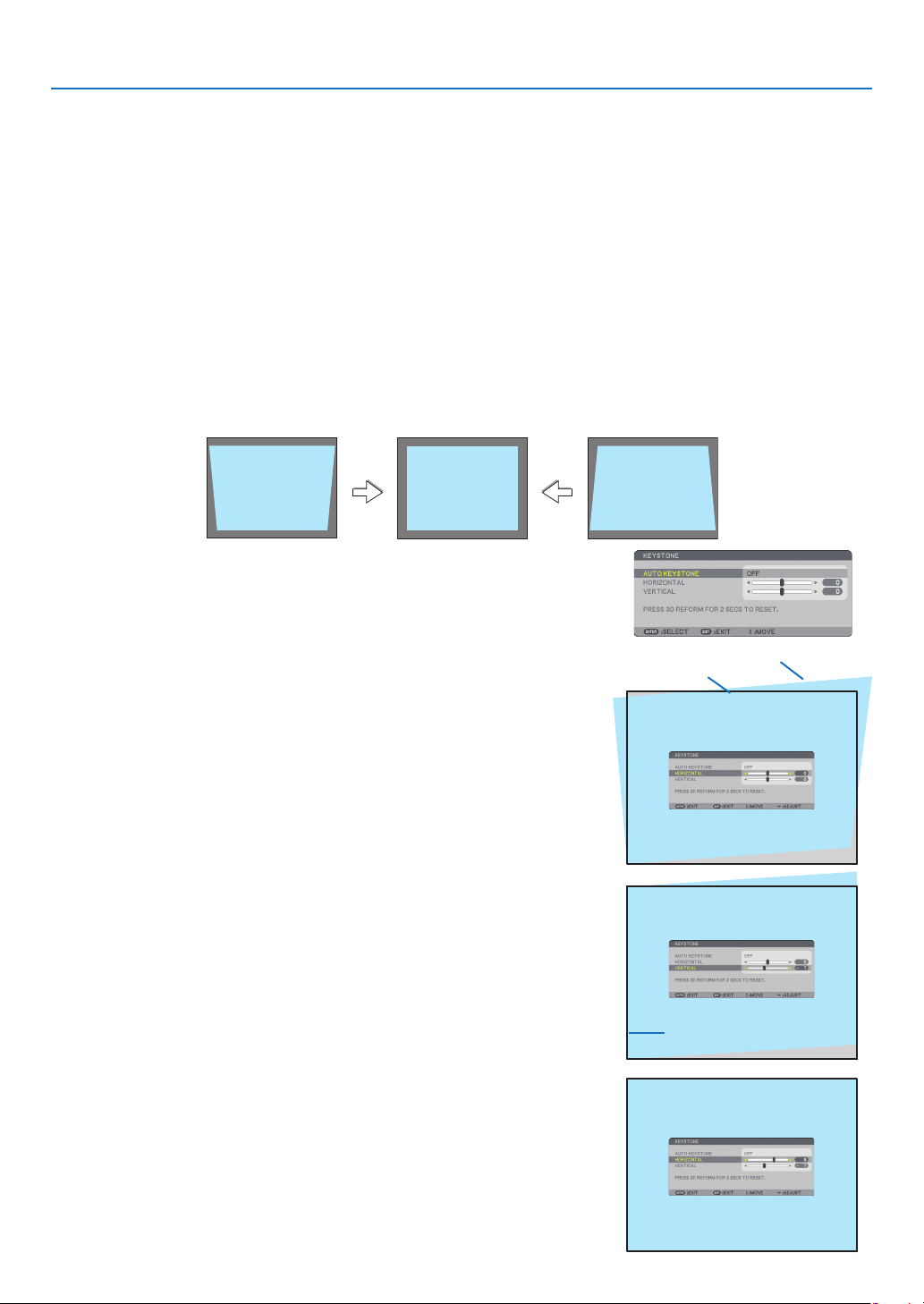
Correcting Keystone Distortion
When the projector is not exactly perpendicular to the screen, keystone distortion occurs. To overcome it, you can
use the “Keystone” function, a digital technology that can adjust for keystone-type distortion, resulting in a crisp,
square image.
The following procedure explains how to use the [KEYSTONE] screen from the menu to correct trapezoidal distor-
tions.
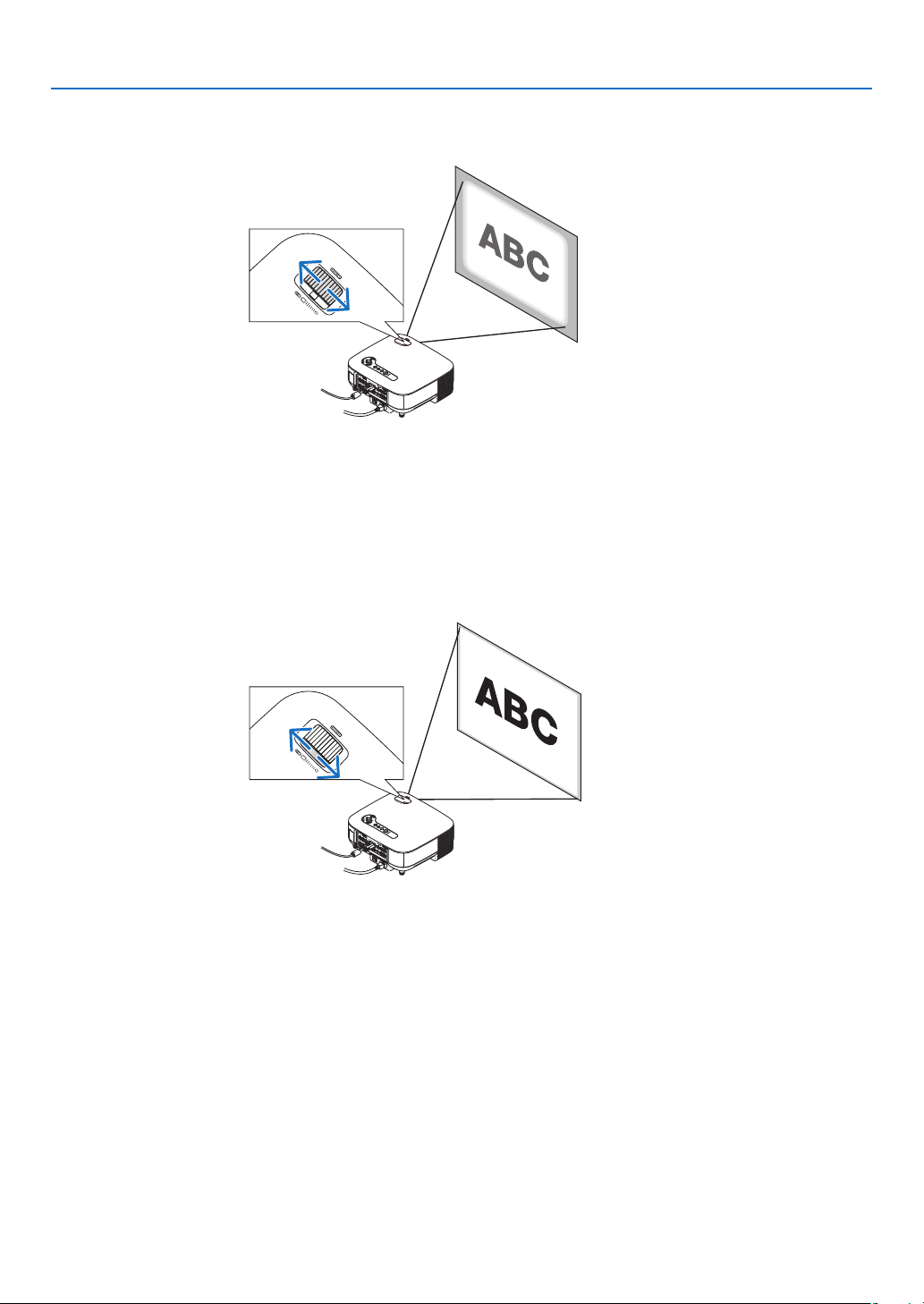
When the projector is set up at an angle in relation to the screen, adjust the Horizontal option of the Keystone
menu so that the top and bottom of sides of the projected image are parallel.
Auto Keystone Correction
The Auto Keystone correction feature will correct vertical distortion of a projected image on the screen. No special
operation required. Just put the projector on a at surface.
To use the Auto Keystone function, rst you must select [AUTO KEYSTONE] in [KEYSTONE] from the menu.
Manual Keystone Correction
1. Press the 3D REFORM button on the remote control or the projec-
tor cabinet.
The Keystone screen will be displayed on the screen.
2. Press the SELECT ▼ button to select [VERTICAL] and then use the
SELECT ◀ or ▶ so that the left and right sides of the projected im-
age are parallel.
* Adjust the vertical keystone distortion.
3. Align the left (or right) side of the screen with the left (or right)
side of the projected image.
• Use the shorter side of the projected image as the base.
• In the right example, use the left side as the base.
4. Press the SELECT ▲ button to select [HORIZONTAL] and then use
the SELECT ◀ or ▶ so that the top and bottom sides of the pro-
jected image are parallel.
• Adjust the horizontal keystone distortion.
Screen frame
Projected area
Align left side

27
3. Projecting an Image (Basic Operation)
NOTE:
• If the projection angle is the same as in the last use, the previous correction setting values are retained in the memory.
To use the previous correction setting values after changing projection angle, select [ON] in [AUTO KEYSTONE] from the
menu.
(→ page 84)
• When doing Step 2, adjust the position of image so that the screen is smaller than the area of the projected area.
• To reset the 3D Reform correction setting values, press and hold the 3D REFORM button for a minimum of 2 seconds.
• Each time the 3D REFORM button is pressed, the item will change as follows: KEYSTONE → CORNERSTONE → None → KEY-
STONE → ...
For information on [CORNERSTONE], see “Correcting Horizontal and Vertical Keystone Distortion (CORNERSTONE)” on page 36.
• The Cornerstone adjustment will not be available during the Keystone adjustment. To perform the Cornerstone adjustment,
press and hold the 3D REFORM button for a minimum of 2 seconds to reset the Keystone correction setting values. The Key-
stone adjustment will not be available during the Cornerstone adjustment. To perform the Keystone adjustment, press and
hold the 3D REFORM button for a minimum of 2 seconds to reset the Cornerstone correction setting values.
• The 3D Reform feature can cause an image to be slightly blurred because the correction is made electronically.
5. Repeat steps 2 and 4 to correct keystone distortion.
6. After completing Keystone correction, press the EXIT button.
The Keystone screen will disappear.
• To perform Keystone correction again, press the 3D REFORM but-
ton to display the Keystone screen and repeat above steps 1 to 6.
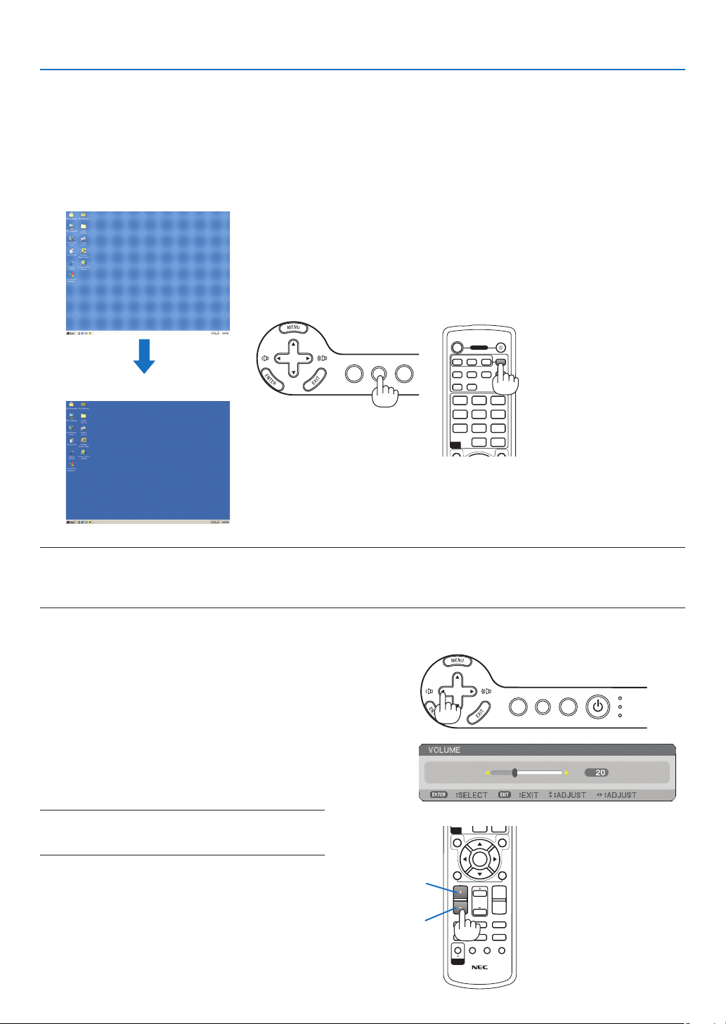
28
3. Projecting an Image (Basic Operation)
MAGNIFYVOLUME
PICTURE
LAMP MODE
ASPECT
AV-MUTE
3D REFORM
FREEZE
ID SET
LENS SHIFT
FOCUS
/ZOOM
HELP
PAGE
MENU
L-CLICK
R-CLICK
EXIT
0
CLEAR
ENTER
UP
DOWN
ID
ID
OFF ON
COMPUTER
VIDEO S-VIDEO
VIEWER
NETWORK
HDMI
PIP
MENU
EXIT
COMPONENT
AUTO ADJ.
1 32
4 65
7 98
0
CLEAR
POWER
ID
123
SOURCE
AUTO ADJUST
3D REFORM
SELECT
❺
Optimizing an RGB Image Automatically
Adjusting the Image Using Auto Adjust
Optimizing an RGB image automatically.
Press the AUTO ADJUST button to optimize an RGB image automatically.
This adjustment may be necessary when you connect your computer for the rst time.
[Poor picture]
[Normal picture]
Sound level from the speaker and the AUDIO
OUT jack (Stereo mini) on the projector can be
adjusted.
Another way to adjust volume is to use the menu.
Select [ADJUST] → [AUDIO] → [VOLUME] from
the menu.
NOTE: Volume control is not available with the SELECT
◀ or ▶ button when an image is enlarged by using the
MAGNIFY (+) button or when the menu is displayed.
NOTE:
• Some signals may take time to display or may not be displayed correctly.
• The Auto Adjust function does not work for component, video signals.
• If the Auto Adjust operation cannot optimize the RGB signal, try to adjust Clock and Phase manually. (→ page 78)
❻
Adjusting Volume Up & Down
Increase volume
Decrease volume
USB
LAMP
STATUS
SOURCE
AUTO ADJUST
3D REFORM
SELECT
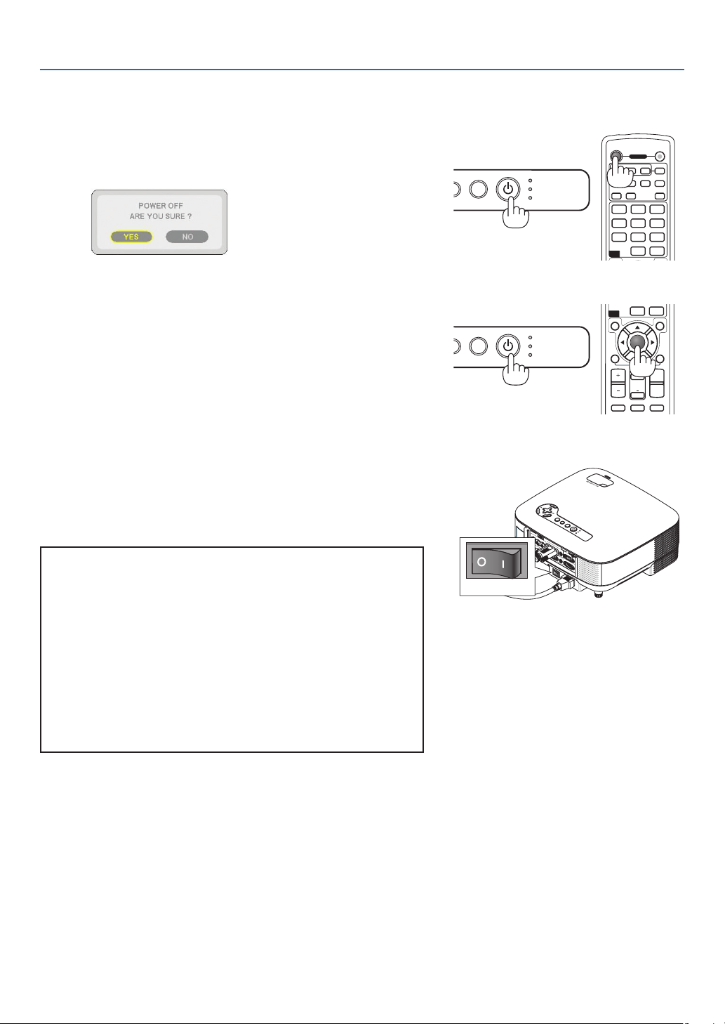
29
3. Projecting an Image (Basic Operation)
OFF ON
COMPUTER
VIDEO S-VIDEO
VIEWER
NETWORK
HDMI
PIP
MENU
EXIT
COMPONENT
AUTO ADJ.
1 32
4 65
7 98
0
CLEAR
POWER
ID
123
USB
LAMP
STATUS
SOURCE
A
DJUST
❼
Turning off the Projector
To turn off the projector:
1. Press the POWER button on the projector cabinet or the
POWER OFF button on the remote control. The [POWER
OFF / ARE YOU SURE?] message will appear.
2. Press the ENTER button
After the projector turns off, the cooling fans keep operating
for a while (Cooling-off time).
The cooling fans stop operating when the projector turns off
and goes into standby mode.
When in standby mode, the POWER indicator will light orange
and the STATUS indicator will light green.
3.
After making sure that the projector is in standby mode, turn
off the Main Power switch. The power indicator will go out.
About Direct Power Off
The projector has a feature called “Direct Power Off”. This fea-
ture allows the projector to be turned off (even when projecting
an image) using a power strip equipped with a switch and a
breaker.
CAUTION
• Do not unplug the power cable from the wall outlet or projec-
tor when the projector is powered on. Doing so can cause
damage to the AC IN connector of the projector and (or)
the prong plug of the power cable. To turn off the AC power
supply when the projector is powered on, use a power strip
equipped with a switch and a breaker.
• Do not turn off the AC power supply within 10 seconds
of making adjustment or setting changes and closing the
menu.
Doing so can cause loss of adjustments and settings and
return to default.
VIDEO IN
AUDIO IN
USB
LAN
AUDIO IN
HDMI IN
AUDIO IN
COMPUTER /
COMPONENT 2 IN
COMPUTER /
COMPONENT 1 IN
PC CONTROL
MONITOR OUT
AUDIO OUT
S-VIDEO IN
AUDIO
I
N
L/MONO
L/MONO
R
R
AC IN
USB
LA
M
P
STATUS
SOURCE
AUTO ADJUST
3D REFORM
SELECT
USB
LAMP
STATUS
SOURCE
A
DJUST
ENTER
MAGNIFYVOLUME
PICTURE
LAMP MODE
ASPECT
PAGE
MENU
L-CLICK
R-CLICK
EXIT
0
CLEAR
UP
DOWN
ID
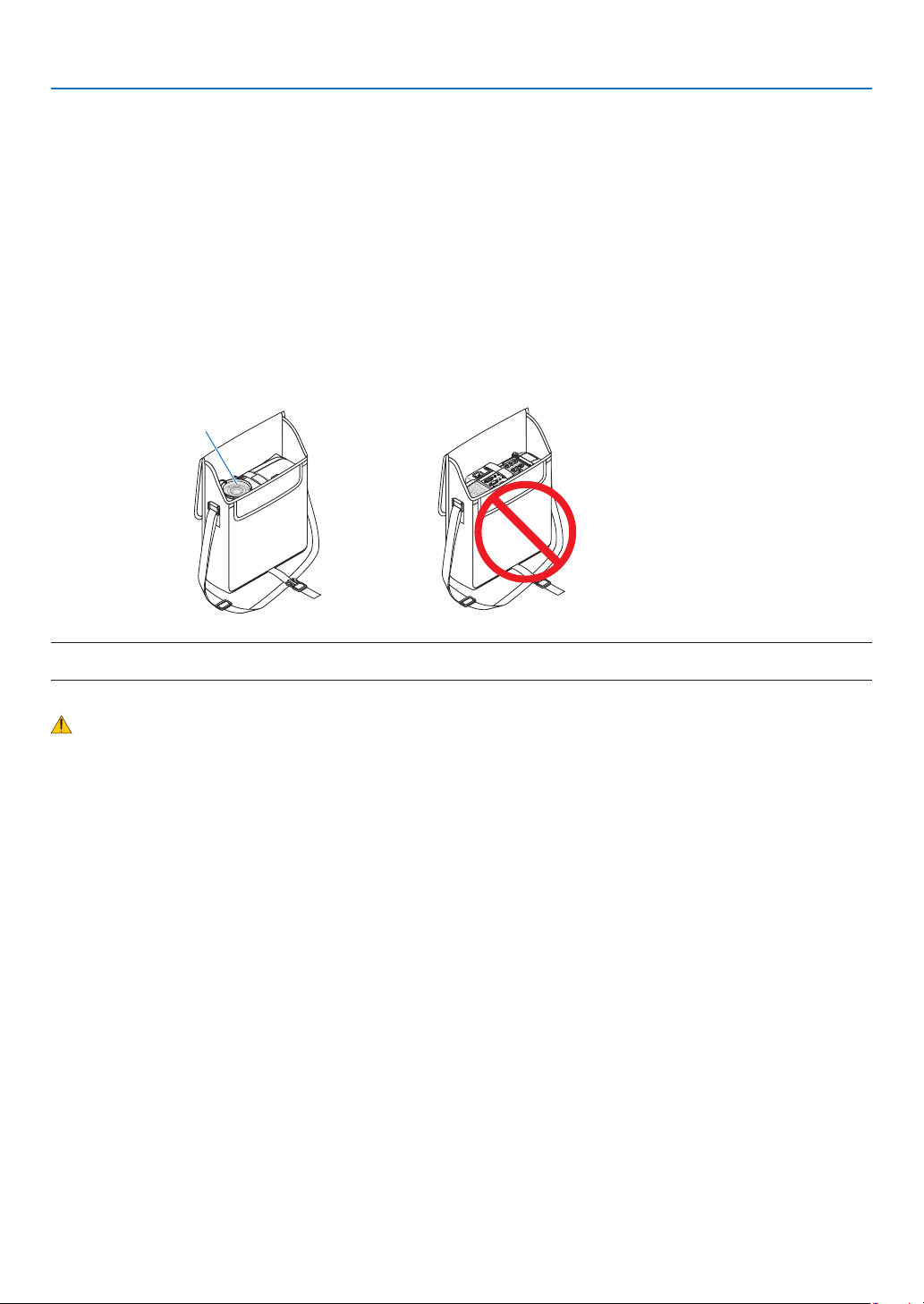
30
3. Projecting an Image (Basic Operation)
❽
After Use
Preparation: Make sure that the main power is turned off.
1. Unplug the power cable.
2. Disconnect any other cables.
3. Retract adjustable tilt feet if extended.
4. Cover the lens with the lens cap.
5. Put the projector and accessories in the supplied soft case.
Place the projector in the soft case with the lens facing upward as shown below. This is to prevent the lens
from damage.
Insert the projector with
the lens facing upward
NOTE: When placing the projector in the soft case, retract the tilt foot and the rear feet. Failure to do so may case damage to the
projector.
CAUTION:
Use caution when putting the projector in the soft case immediately after the projector has been operating. The
projector cabinet is hot.
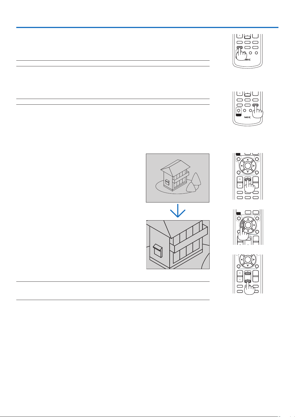
31
PICTURE
LAMP MODE
ASPECT
AV-MUTE
3D REFORM
FREEZE
ID SET
LENS SHIFT
FOCUS
/ZOOM
HELP
DOWN
ID
4. Convenient Features
❶
Turning Off the Image and Sound
Press the AV-MUTE button to turn off the image and sound for a short period of
time. Press again to restore the image and sound.
NOTE: Even though the image is turned off, the menu still remains on the screen.
❷
Freezing a Picture
Press the FREEZE button to freeze a picture. Press again to resume motion.
NOTE: The image is frozen but the original video is still playing back.
❸
Enlarging and Moving a Picture
You can enlarge the area you want up to 400 percent.
To do so:
1. Press the MAGNIFY (+) button.
Each time the MAGNIFY (+) button is pressed,
the image is magnified.
* Image can be magnified up to 400%
2. Press the SELECT ▲▼◀ ▶ button.
The area of the magnified image will be moved
3. Press the MAGNIFY (-) button.
Each time the MAGNIFY (-) button is pressed,
the image is reduced.
MAGNIFYVOLUME
PAGE
MENU
L-CLICK
R-CLICK
EXIT
0
CLEAR
ENTER
UP
DOWN
ID
PICTURE
LAMP MODE
ASPECT
AV-MUTE
3D REFORM
FREEZE
ID SET
LENS SHIFT
FOCUS
/ZOOM
HELP
DOWN
ID
MAGNIFYVOLUME
PICTURE
LAMP MODE
ASPECT
AV-MUTE
3D REFORM
FREEZE
FOCUS
PAGE
MENU
L-CLICK
R-CLICK
EXIT
0
CLEAR
ENTER
UP
DOWN
ID
MAGNIFYVOLUME
PICTURE
LAMP MODE
ASPECT
AV-MUTE
3D REFORM
FREEZE
FOCUS
PAGE
L-CLICK
R-CLICK
ENTER
UP
DOWN
NOTE:
• The image will be displayed at the center of the screen.
• Displaying the menu will return the image size to the default.
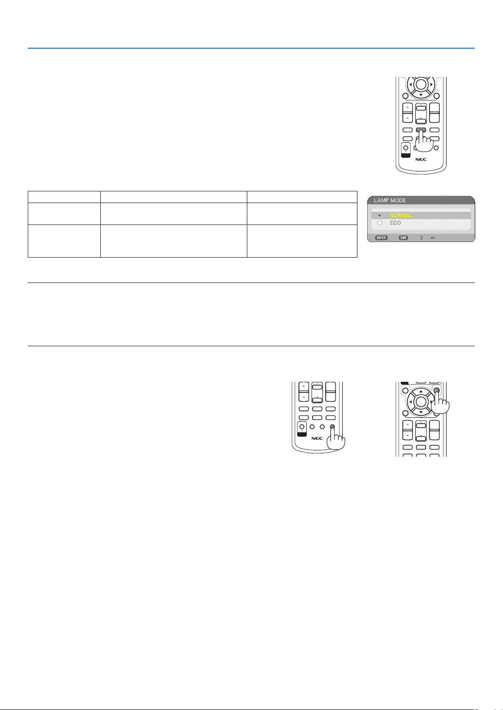
32
4. Convenient Features
PICTURE
LAMP MODE
ASPECT
AV-MUTE
3D REFORM
FREEZE
ID SET
LENS SHIFT
FOCUS
/ZOOM
HELP
UP
DOWN
ID
4. Convenient Features
❺
Getting Integrated Help
You get the contents about Help in English, German and Japa-
nese.
1. Press the HELP button on the remote control.
• When no menus appear, the “How to Use Help” screen will
be displayed.
•
When menus appear, the screen will be displayed, explain-
ing the function of a highlighted item.
2. Use the SELECT ▲ or ▼ button to scroll the viewing area.
3. Press the EXIT button.
• The Help will be closed.
Display Help
Exit Help
❹
Changing Lamp Mode
The lamp life can be extended by using the Eco mode.
To change to the [ECO] mode, do the following:
1. Press the LAMP MODE button to display [LAMP MODE] screen.
2. Use the SELECT ▲ or ▼ button to select [ECO] mode.
3. Press the ENTER button.
To cancel it, press the EXIT button.
To change from [ECO] to [NORMAL], Go back to Step 2 and select [NORMAL].
Repeat Step 3.
Lamp Mode Description Status of LAMP indicator
NORMAL
This is the Default setting
(100% Brightness).
Off
ECO
Select this mode to increase the
lamp life (approx. 80% Brightness
light output)
Steady Green light
NOTE:
• The projector is always in [NORMAL] for one minute after the lamp is turned on and while the POWER indicator is blinking
green. The lamp condition will not be affected even when [LAMP MODE] is changed.
• After a lapse of one minute from when the projector displays a blue, black or logo screen, [LAMP MODE] will automatically
switch to [ECO].
The projector will return to the [NORMAL] once a signal is accepted.
MAGNIFYVOLUME
PICTURE
LAMP MODE
ASPECT
AV-MUTE
3D REFORM
FREEZE
PAGE
MENU
L-CLICK
R-CLICK
EXIT
ENTER
UP
DOWN
ID
MAGNIFYVOLUME
PICTURE
LAMP MODE
ASPECT
AV-MUTE
3D REFORM
FREEZE
ID SET
LENS SHIFT
FOCUS
/ZOOM
HELP
PAGE
L-CLICK
R-CLICK
ENTER
UP
DOWN
ID
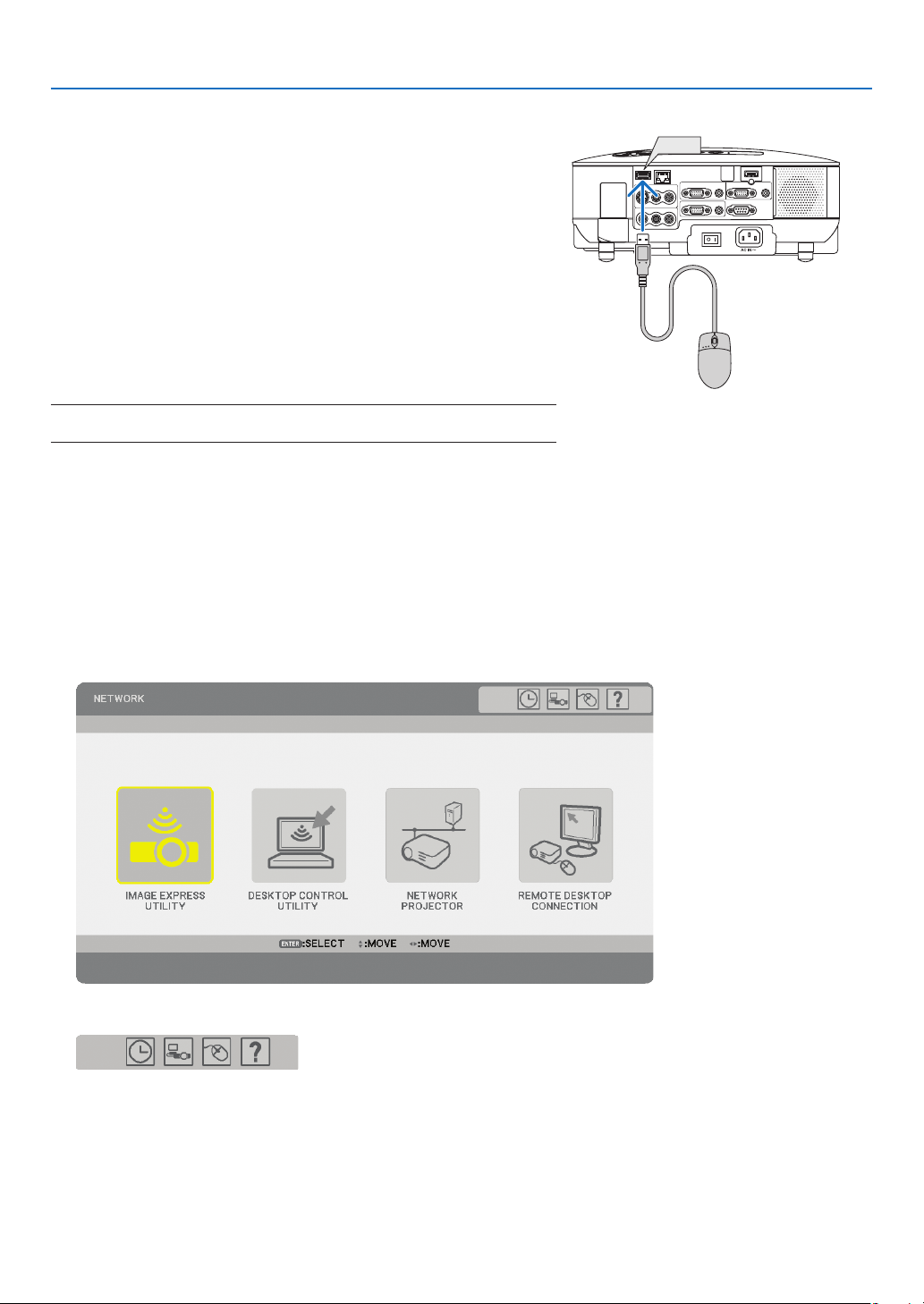
33
4. Convenient Features
Operate the Menus using the USB mouse
Mouse Cursor
When connecting a USB mouse to the projector, you get a mouse cursor on the screen.
Unless you use your USB mouse within 10 seconds, the mouse cursor disappears.
Adjusting and Setting Display
You can select a menu item and click with the left mouse button to make adjustments and settings.
With the middle button you can use a scroll bar in the menu or the help.
Icons on the top right of the menu
• Click [Clock] symbol to display the [DATE, TIME PRESET] menu.
• Click [Network] symbol to display the [NETWORK SETTINGS] menu. (→ page
95)
• Click [Mouse] symbol to display the [MOUSE] menu.
• Click [?] to display a selection of the selected menu item.
❻
Using a USB Mouse
Using a USB mouse gives you a smooth operation. A commercially
available USB mouse can be used.
Menu items that can be operated with your USB mouse are:
• VIEWER
• NETWORK
• ENTRY LIST
• TOOLS
• SECURITY SETTINGS
• NETWORK SETTINGS
• CORNERSTONE
NOTE: We do not warrant that the USB port of the projector will support all
USB mouse devices in the market.
WIRELESS
WIRELESS
VIDEO IN
AUDIO IN
USB
LAN
AUDIO IN
HDMI IN
AUDIO IN
COMPUTER /
COMPONENT 2 IN
COMPUTER /
COMPONENT 1 IN
PC CONTROL
MONITOR OUT
AUDIO OUT
S-VIDEO IN
AUDIO IN
L/MONO
L/MONO
R
R
USB
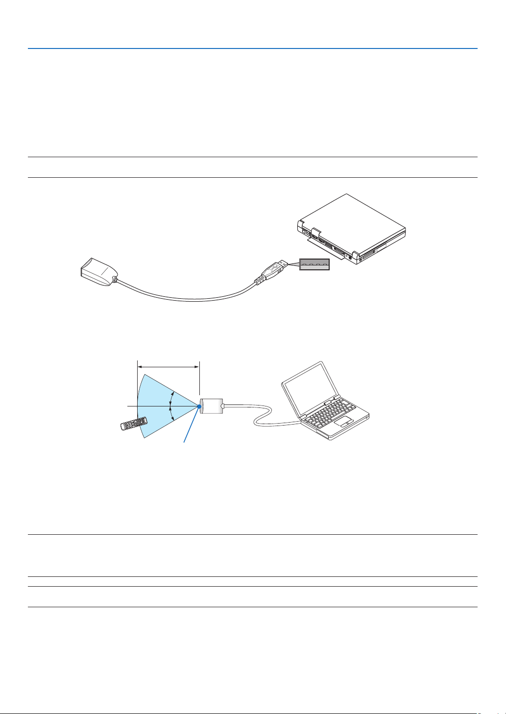
34
4. Convenient Features
❼
Using the Optional Remote Mouse Receiver (NP01MR)
The optional remote mouse receiver enables you to operate your computer’s mouse functions from the remote
control. It is a great convenience for your computer-generated presentations.
Connecting the remote mouse receiver to your computer
If you wish to use the remote mouse function, connect the mouse receiver and computer.
The mouse receiver can be connected directly to the computer’s USB port (type A).
NOTE: Depending on the type of connection or OS installed on your computer, you may have to restart your computer or change
your computer settings.
30°
30°
Remote mouse receiver
Computer
To USB port of PC or Macintosh
When operating a computer via the remote mouse receiver
Remote sensor on the remote mouse receiver
22 feet/7 m
When connecting using the USB port
For PC, the mouse receiver can only be used with a Windows 98/Me/XP*, Windows 2000, Windows Vista, or
Mac OS X 10.0.0 or later operating system.
* NOTE: In SP1 or older version of Windows XP, if the mouse cursor will not move correctly, do the following:
Clear the Enhance pointer precision check box underneath the mouse speed slider in the Mouse Properties dialog box [Pointer
Options tab].
• The PAGE UP and DOWN buttons do not work with PowerPoint for Macintosh.
NOTE: Wait at least 5 seconds after disconnecting the mouse receiver before reconnecting it and vice versa. The computer may
not identify the mouse receiver if it is repeatedly connected and disconnected in rapid intervals.

35
4. Convenient Features
Operating your computer’s mouse from the remote control
You can operate your computer’s mouse from the remote control.
PAGE UP/DOWN Button ..................scrolls the viewing area of the window or to move to the previous or next slide in Pow-
erPoint on your computer.
SELECT ▲▼◀ ▶ Button ..................moves the mouse cursor on your computer.
MOUSE L-CLICK Button ..................works as the mouse left button.
MOUSE R-CLICK Button .................works as the mouse right button.
NOTE:
• When you operate the computer using the SELECT ▲▼◀ ▶ button with the menu displayed, both the menu and the mouse
pointer will be affected. Close the menu and perform the mouse operation.
• The PAGE UP and DOWN buttons do not work with PowerPoint for Macintosh.
About Drag Mode:
By pressing the MOUSE L-CLICK or R-CLICK button for 2 or 3 seconds then releasing, the drag mode is set and
the drag operation can be performed simply by pressing the SELECT ▲▼◀ ▶ button. To drop the item, press the
MOUSE L-CLICK (or R-CLICK) button. To cancel it, press the MOUSE R-CLICK (or L-CLICK) button.
TIP: You can change the Pointer speed on the Mouse Properties dialog box on the Windows. For more information, see the user
documentation or online help supplied with your computer.
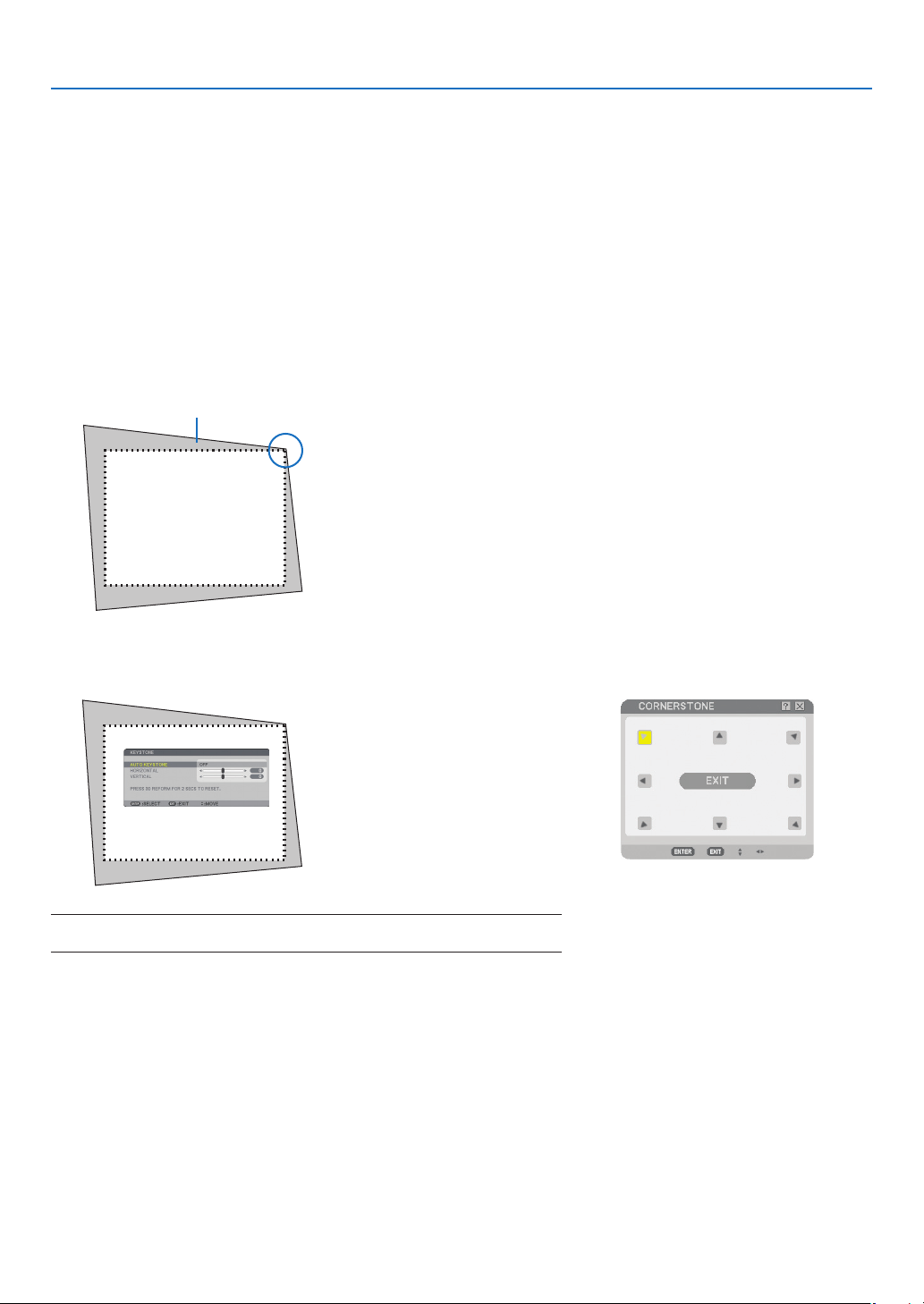
36
4. Convenient Features
❽
Correcting Horizontal and Vertical Keystone Distortion (Cornerstone)
Use the 3D Reform feature to correct keystone (trapezoidal) distortion to make the top or bottom and the left or
right side of the screen longer or shorter so that the projected image is rectangular.
Projected image
Cornerstone
1. Press and hold the 3D REFORM button for a minimum of 2 seconds to reset current adjustments.
Current adjustments for [KEYSTONE] or [CORNERSTONE] will be cleared.
2. Project an image so that the screen is smaller than the area of the raster.
3. Pick up any one of the corners and align the corner of the image with a corner of the screen.
The drawing shows the up-
per right corner.
4. Press the 3D REFORM button twice.
The Cornerstone adjustment screen is displayed.
5. Use the SELECT ▲▼◀ ▶ button to select one icon (▲) which points in the direction you wish to move the
projected image frame.
6. Press the ENTER button.
Screen
NOTE: When the [CORNERSTONE] screen is displayed, the background will
temporarily turn black and a frame will appear as an adjusting guide.
TIP: If you are adjusting [KEYSTONE], [CORNERSTONE] will not be available. If
this happens, press and hold the 3D REFORM button for a minimum of 2 sec-
onds to reset the [KEYSTONE] adjustments.
The drawing shows the upper
left icon (
) is selected.
▼
TIP: When [WIDE SCREEN] is selected from [SCREEN TYPE], lines
that show "16:9" will be displayed both at the top and bottom. Click
the outer corners.
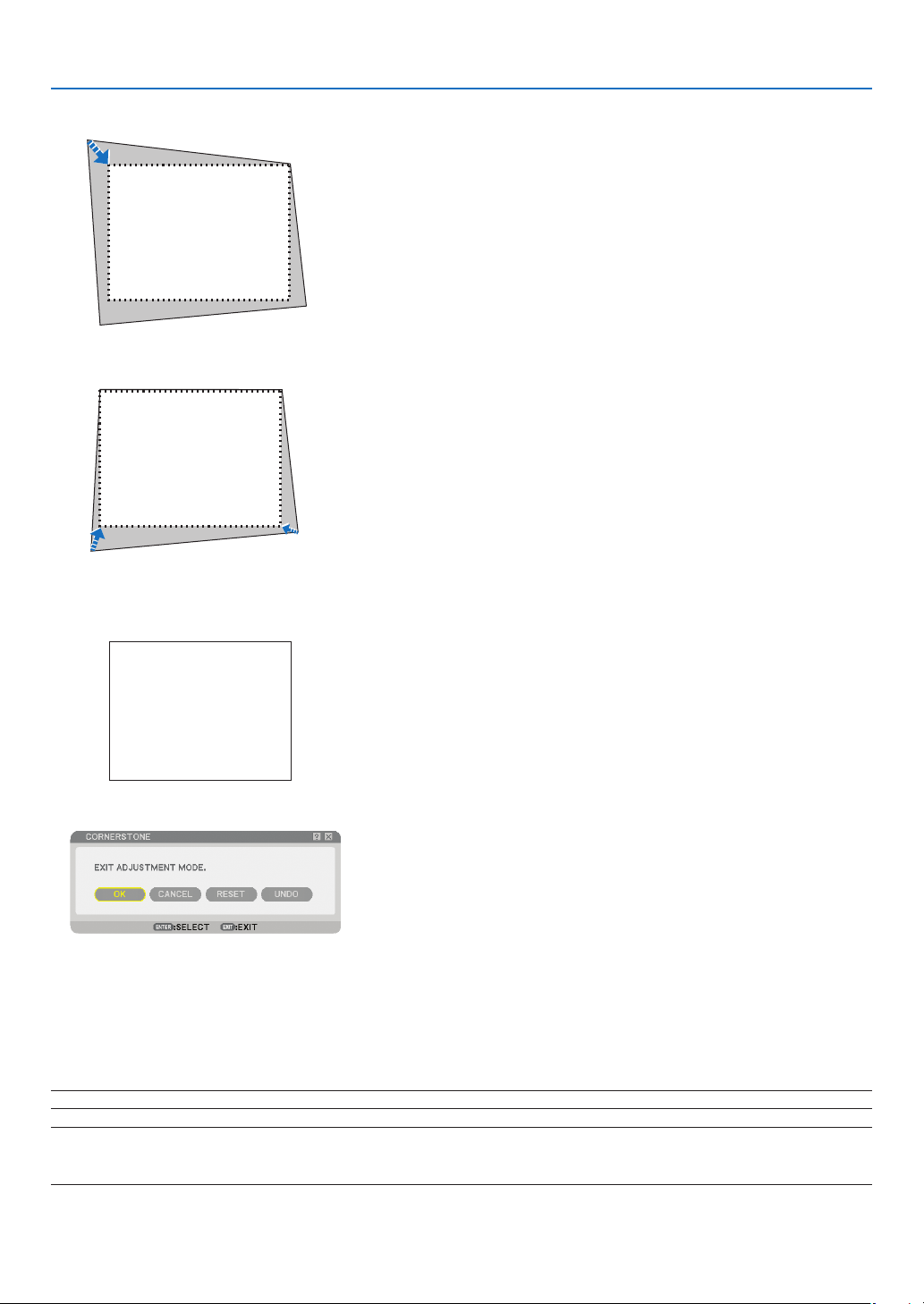
37
4. Convenient Features
8. Press the ENTER button.
10
. Press the SELECT ◀ or ▶ button to highlight the [OK] and press the ENTER button.
This completes the Cornerstone correction.
Selecting [CANCEL] will return to the adjustment screen without saving changes (Step 3).
Selecting [RESET] will return to the factory default.
Selecting [UNDO] will exit without saving changes.
NOTE: To reset the 3D Reform correction setting values, press and hold the 3D REFORM button for a minimum of 2 seconds.
NOTE: During 3D Reform adjustment, [ASPECT RATIO] and [SCREEN] may not be available. Should this happen, fi rst reset the
3D Reform data and then do each setting. Second repeat the 3D Reform adjustment. Changing [ASPECT RATIO] and/or [SCREEN]
setting can limit 3D REFORM in its adjustable range.
Screen
9. Use the SELECT ▲▼◀ ▶ button to select another icon which points in the direction.
On the Cornerstone adjustment screen, select [EXIT] or press the EXIT button on the remote control.
The confirmation screen is displayed.
7. Use the SELECT ▲▼◀ ▶ button to move the projected image frame as shown on the example.
Screen
Screen

38
4. Convenient Features
* The following are conditions under which the maximum angle is achieved:
• Image is projected in Wide (Zoom lever to the maximum)
NOTE:
• Even when the projector is turned on, the last used correction values are applied.
• Turning on the projector will reset the previous correction setting values and correct distortion anew if the projection angle is
changed from the last use.
If the projection angle is the same as in the last use, the previous correction setting values are retained in the memory.
• The range of keystone correction is not the maximum tilt angle of projector.
NOTE: Using 3D Reform correction can cause the image to be slightly blurred because the correction is made electronically.
The adjustable ranges for 3D Reform are as follows:
HORIZONTAL VERTICAL
CORNERSTONE
KEYSTONE
Max. +/– 30° approx.Max. +/– 40° approx.
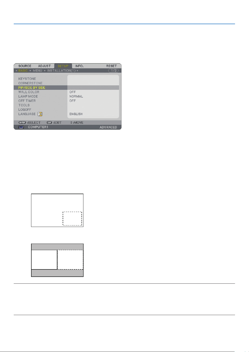
39
4. Convenient Features
❾
Displaying Two Pictures at the Same Time
The projector has a feature that allows you to view two different signals simultaneously. You have two modes: PIP
mode and Side by Side mode.
From the menu you can select [SETUP] → [BASIC] → [PIP/SIDE BY SIDE].
The [PIP/SIDE BY SIDE] menu item has the following three options: MODE, POSITION, and SOURCE.
Use the SELECT ▲ or ▼ button to select [MODE], [POSITION] or [SOURCE] and press the ENTER button.
Selecting the PIP or SIDE BY SIDE Mode [MODE]
This option allows you to select two modes: PIP and SIDE BY SIDE.
Use the SELECT ▲ or ▼ button to select [PIP] or [SIDE BY SIDE] and press the ENTER button.
PIP: This option allows you to view a sub picture in the main picture.
SIDE BY SIDE: This allows you to view two pictures side by side.
NOTE:
• The main picture will be displayed on the left side and the sub picture on the right side.
• The main picture signal supports the COMPUTER 1 IN/COMPONENT 1 IN and the COMPUTER 2 IN/COMPONENT 2 IN con-
nectors.
The sub picture signal supports the VIDEO IN and S-VIDEO IN connectors.
• The main picture supports an RGB signal with a resolution of 1280 x 1024 pixels or less.
Main picture
Sub
picture
Main picture Sub picture
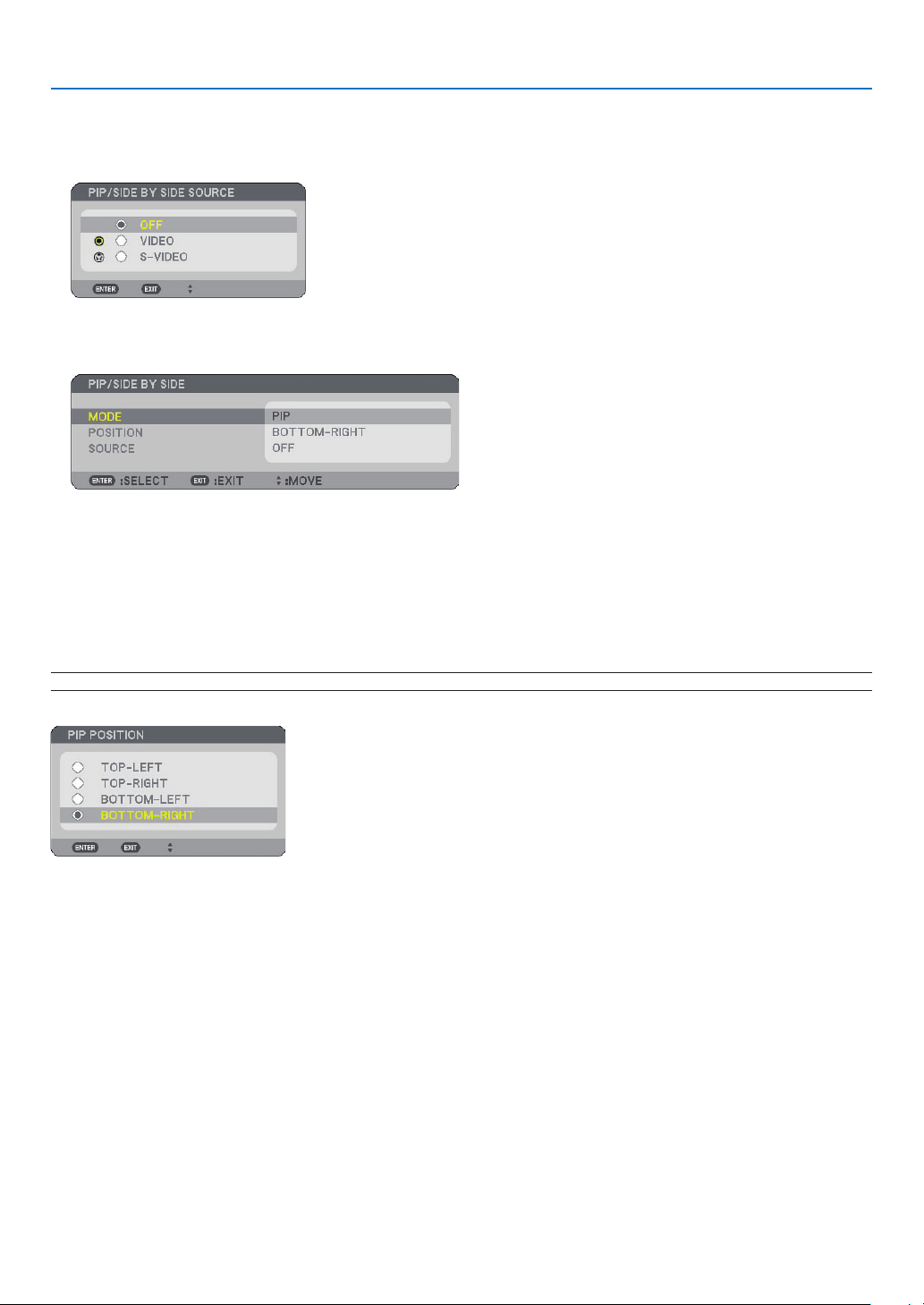
40
4. Convenient Features
Viewing Two Pictures
1. Press the PIP button on the remote control.
The PIP/SIDE BY SIDE source screen will be displayed.
2. Use the SELECT ▲ or ▼ button to select the source and press the ENTER button.
The PIP screen or SIDE BY SIDE screen will be displayed, depending on which was selected in the [MODE]
setting screen.
3. Press the PIP button again to return to the normal screen (single picture).
TIP:
• Selecting another source will return to the normal screen.
• Selecting a source not supported for the main picture or the sub picture will return to the normal screen.
POSITION
This option allows you to select the position of a sub picture in the main picture.
NOTE: The default setting is [BOTTOM-RIGHT].
Use the SELECT ▲ or ▼ button to select the sub picture’s position and press the ENTER button.
The options are: TOP-LEFT, TOP-RIGHT, BOTTOM-LEFT, and BOTTOM-RIGHT.
The following adjustments and settings are available for the main picture only.
- Adjusting picture and sound
- Magnifying a picture
The following operations are available for both the main and sub pictures.
- Picture and audio mute
- Freezing a moving picture
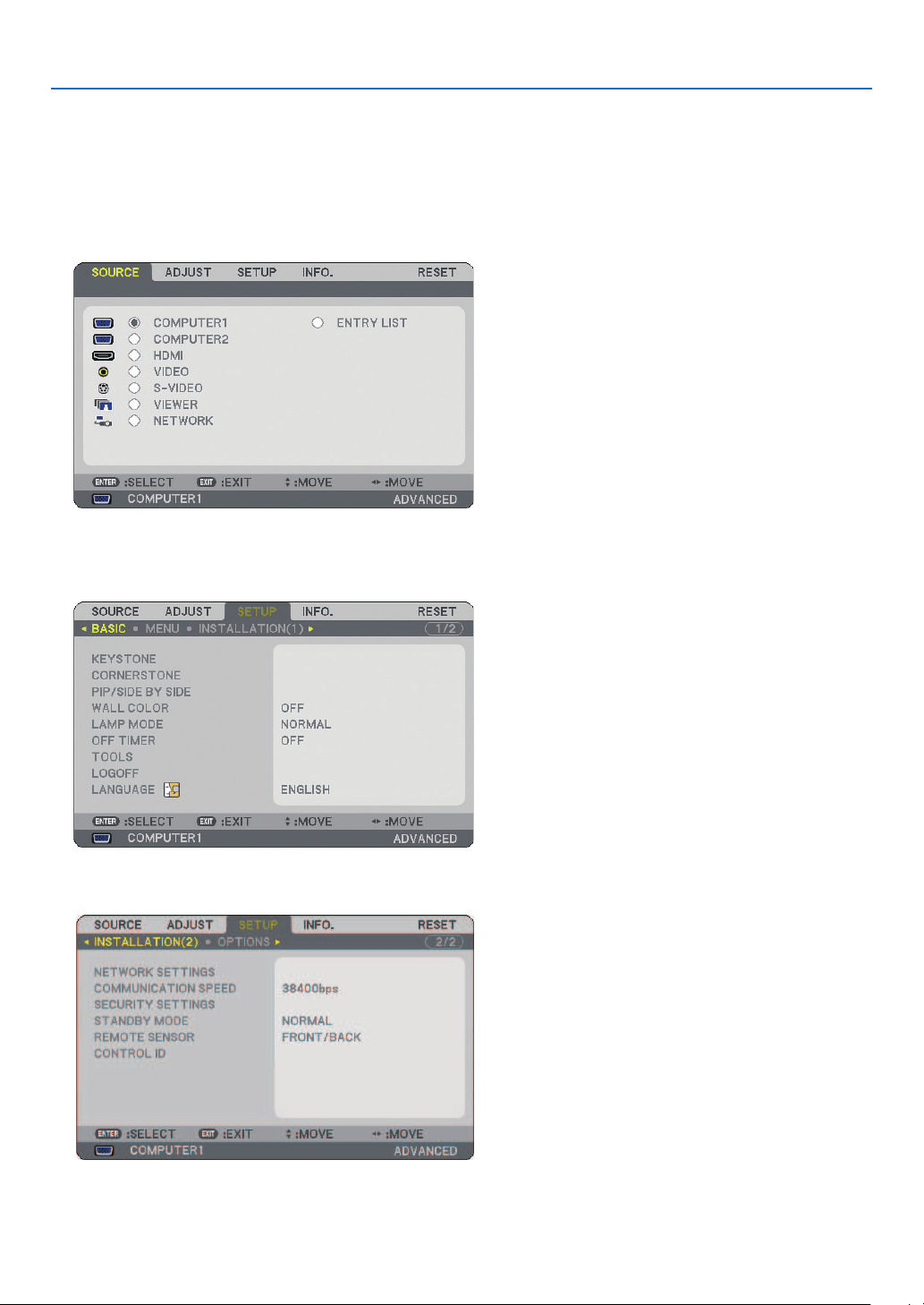
41
4. Convenient Features
❿
Preventing Unauthorized Use of the Projector
Assigning a keyword prevents the projector from being used by unauthorized individuals.
Turning on the Security function by assigning a keyword for the fi rst time
1. Press the MENU button.
The menu will be displayed.
2. Press the SELECT ▶ button to highlight the [SETUP] submenu and press the ENTER button.
The page tab [BASIC] will be highlighted.
3. Press the SELECT ▶ button three times to highlight the page tab [INSTALLATION(2)].
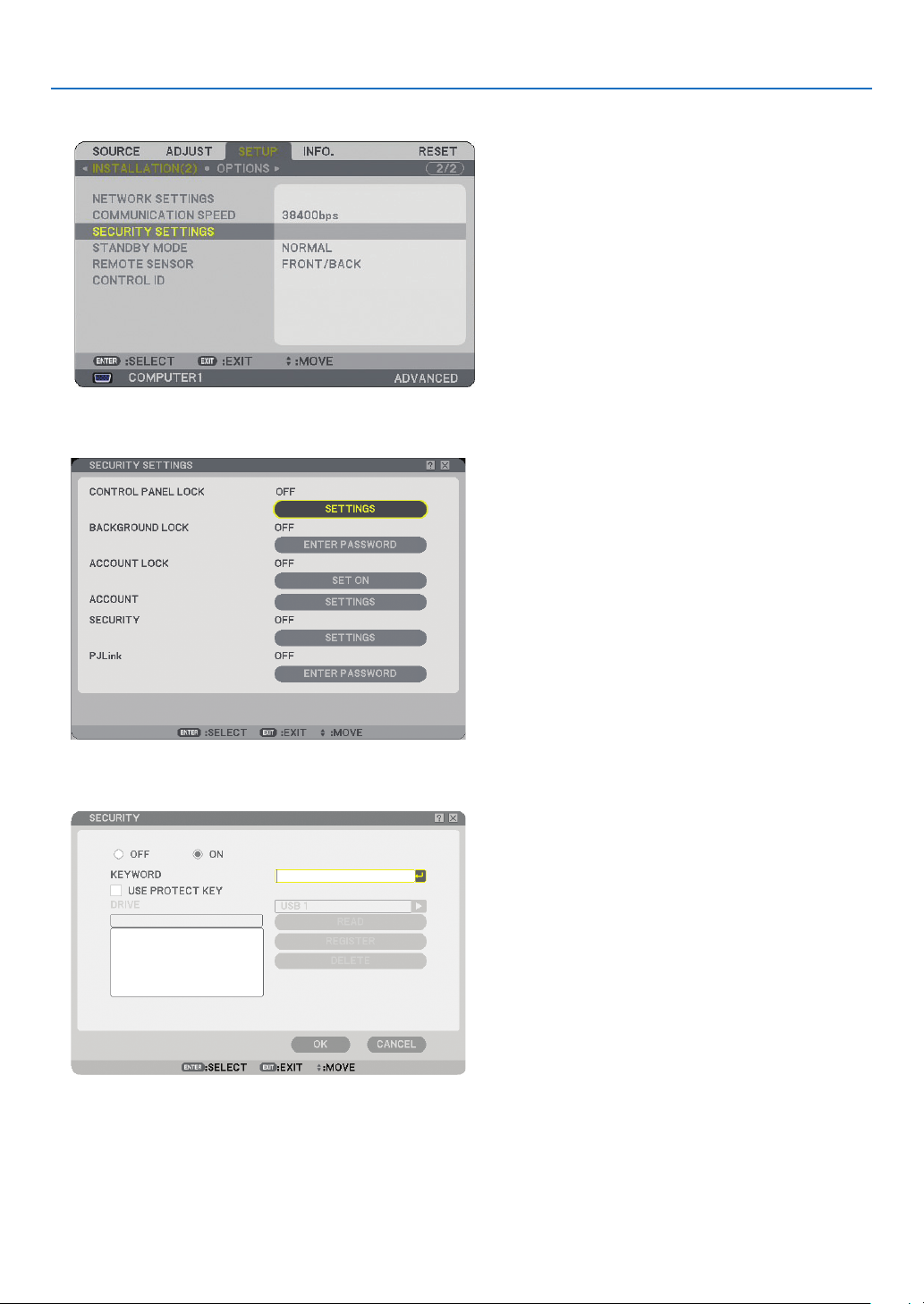
42
4. Convenient Features
4. Press the SELECT ▼ button three times to highlight [SECURITY SETTINGS].
5. Press the ENTER button to display the SECURITY SETTINGS menu.
6.
Press the SELECT ▼ button four times to highlight [SECURITY SETTINGS] and press the ENTER button.
The Security screen will be displayed.
7. Press the SELECT ▼ button once to highlight the Keyword entry box and press the ENTER button.
The Software keyboard will be displayed.
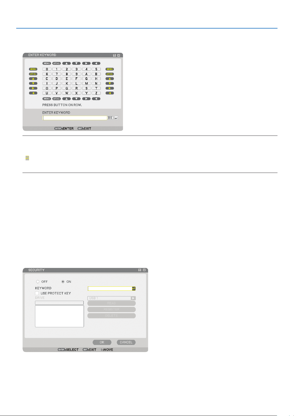
43
4. Convenient Features
8. Enter an alphanumeric keyword using the Software keyboard.
For example, to enter “1234”, follow the steps 8-1 to 8-4 below.
NOTE:
• When using your USB mouse, click each number or alphabet.
BS: Delete the character before the cursor or highlight.
: Confi rm the keyword and close the Software keyboard.
• The keyword must be 1 to 10 characters long.
• Please make a note of your keyword.
Enter a keyword by using the remote control.
8-1. Press the MENU button and the AUTO ADJ. button to enter “1”.
The asterisk “*” will be displayed in the keyword entry box.
8-2. Press the MENU button and the SELECT ▲ button to enter “2”.
The asterisk “**” will be displayed in the keyword entry box.
8-3. Press the MENU button and the SELECT ▼ button to enter “3”.
The asterisk “***” will be displayed in the keyword entry box.
8-4. Press the MENU button and the SELECT ▶ button to enter “4”.
The asterisk “****” will be displayed in the keyword entry box.
8-5. Press the ENTER button.
9. Press the SELECT ▲ button once to highlight [OFF] and press the SELECT ▶ button to highlight [ON].
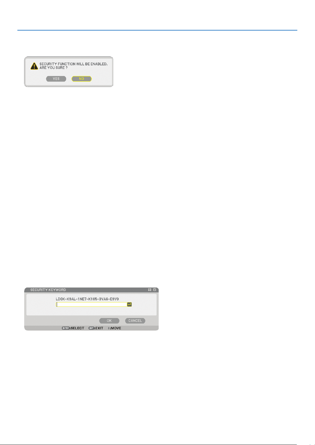
44
4. Convenient Features
10
. Press the SELECT ▼ button to highlight [OK] and press the ENTER button.
The confirmation screen will be displayed.
11
. Press the SELECT ◀ or ▶ button to highlight [YES] and press the ENTER button.
The Security Function will take effect when the projector is turned on next time.
Checking If Security is enabled
Turn off the projector and turn it back on to check if the Security function is enabled.
1. Press the POWER button.
The [POWER OFF / ARE YOU SURE?] message will appear.
Press the ENTER button or the POWER or the POWER OFF button again.
The lamp lights off and the POWER indicator flashes orange. Please wait until the POWER indicator changes
from flashing to steady light.
2. When the POWER indicator lights steady orange, push the Main POWER switch to the off position (○).
The projector will turn off.
3. Push the Main POWER switch to the on position (I).
The POWER indicator lights orange. The projector is in standby condition.
4. Press and hold the POWER button for a minimum of two seconds.
The projector will turn on. The [PROJECTOR IS LOCKED! ENTER YOUR KEYWORD.] message will be dis-
played at the bottom of the screen.
5. Press the MENU button.
The Keyword entry screen will be displayed
6. Press the ENTER button.
The Software keyboard will be displayed.
7. Use the same procedures as steps 1 to 8 described in the “Assigning a Keyword for the first time” sec-
tion to enter “1234”.
Each time one number is entered, an “*” (asterisk) will appear. Keyword appears as asterisks so the real key-
word is hidden.
8. After entering your keyword, highlight [OK] and press the ENTER button.
The Software keyboard will disappear. This will allow you to operate the projector.
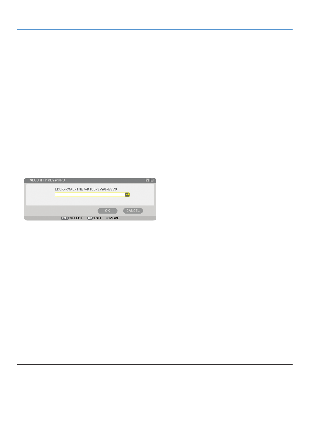
45
4. Convenient Features
Disabling the Security
1. Press the MENU button.
The menu will be displayed.
NOTE: Immediately after the projector has been turned on and the “PROJECTOR IS LOCKED! ENTER YOUR KEYWORD.” mes-
sage is displayed at the bottom of the screen, pressing the MENU button will display the Keyword entry will be displayed. At
this time, pressing the MENU button will display the menu.
2. Press the SELECT ▶ button to highlight [SETUP] and press the ENTER button.
The page tab [BASIC] will be highlighted.
3. Press the SELECT ▶ button twice to highlight the page tab [INSTALLATION(2)].
4. Press the SELECT ▼ button three times to highlight [SECURITY SETTINGS] and press the ENTER button.
5. Press the SELECT ▼ button four times to highlight [SECURITY] → [SETTINGS] and press the ENTER but-
ton.
The Keyword entry screen will be displayed
6. Press the ENTER button.
The Software keyboard will be displayed.
7. Use the same procedures as steps 1 to 8 described in the “Assigning a Keyword for the first time” sec-
tion to enter “1234”.
Each time one number is entered, an “*” (asterisk) will appear. Keyword appears as asterisks so the real key-
word is hidden.
8. After entering your keyword, highlight [OK] and press the ENTER button.
The Software keyboard will disappear. The Security screen will be displayed.
9. Highlight [ON] and press the SELECT ◀ button to highlight [OFF].
10
. Press the SELECT ▼ button to highlight [OK] and press the ENTER button.
The Security Function will be disabled when the projector is turned on next time.
NOTE: Do not forget your keyword. However, if you forget your keyword, NEC or your dealer will provide you with your Release
Code upon proof of ownership.

46
4. Convenient Features
⓫
Limiting Access Level to Available Menu Items
The Account function allows you to manage available menu items by user level.
The projector has two menu modes: the ADVANCED menu and the BASIC menu.
ADVANCED menu .. This is the menu that contains all the available menus and commands. Users with an ADMINISTRATOR
or ADVANCED account can access the ADVANCED menu.
BASIC menu .......... This is the basic menu that contains minimum essentials of menus and commands. Users with a BA-
SIC account can access the BASIC menu.
See page
47 for settings available to ADVANCED and BASIC menus.
NOTE:
• A user with an ADMINISTRATOR account that has no password set is registered at the factory.
This will allow the user to access the ACCOUNT items without password entry.
Logging On
Logging on your projector
When a user is registered, trying to display the menu will display the LOGON screen, prompting the user to select
the user and to enter the password.
NOTE: If one user logs on to the projector, any other user cannot log on.
1. Enter a user name.
2. Enter the registered password if you have it.
3. Select [OK].
NOTE: Do not forget your password. If you forget your password, ask your administrator. If your administrator forget the pass-
word, ask NEC or your dealer. NEC or your dealer will provide you with your Release Code (24 character length) upon proof of
ownership.
Logging Off
Logging off your projector
Logging off your projector will prevent an unauthorized user from operating your projector.
1. From the menu, select [SETUP] → [BASIC] → [LOGOFF].
2. Select [YES].
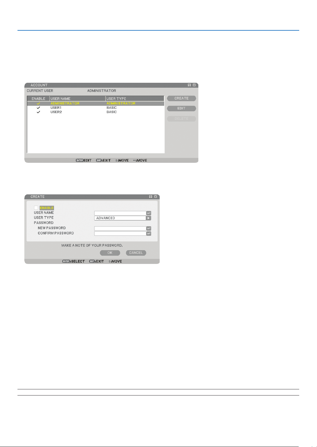
47
4. Convenient Features
Creating or Adding a User
1. From the menu, select [SETUP] → [INSTALLATION(2)] → [SECURITY SETTINGS].
2. Select [ACCOUNT] → [SETTINGS].
The [ACCOUNT] setting screen will be displayed.
3. Select [CREATE].
The [ACCOUNT] create screen will be displayed.
4. Enter a user name, user type, and password.
• A user name must be 16 alphanumeric characters or less (case sensitive).
• User type has two options: [ADVANCED] and [BASIC].
• Use the software keyboard to enter a password in the NEW PASSWORD entry eld.
A password must be 10 alphanumeric characters or less. If no password is set, the user is registered without
a password.
• After entering a password, enter the same password in [CONFIRM PASSWORD] input screen again.
• Make a note of your password.
5. Place a checkmark on [ENABLE].
The account will be made available.
6. Select [OK].
This will complete adding a user.
NOTE: Up to 12 user names can be created.

48
4. Convenient Features
Editing a User (Changing Account Settings)
1. From the menu, select [SETUP] → [INSTALLATION(2)] → [SECURITY SETTINGS].
NOTE: A user with an ADMINISTRATOR account is recommended to change the account settings.
2. Select [ACCOUNT] → [SETTINGS].
The [ACCOUNT] setting screen will be displayed.
3. Select a user name you wish to edit.
4. Select [EDIT].
The [EDIT] screen will be displayed.
Enter your password and press the ENTER button.
If no password is set, simply press the ENTER button without entering any password.
5. Change the settings and select [OK].
Deleting a User
1. From the menu, select [SETUP] → [INSTALLATION(2)] → [SECURITY SETTINGS].
NOTE: A user with an ADMINISTRATOR account is recommended to delete the account settings.
2. Select [ACCOUNT] → [SETTINGS].
The [ACCOUNT] setting screen will be displayed.
3. Select a user name you wish to delete.
4. Select [DELETE].
The [DELETE] screen will be displayed.
Enter your password and press the ENTER button.
The confirmation screen will be displayed.
5. Select [YES].
This will complete deleting the user.
NOTE: Do not forget your password. If you forget your password, ask your administrator. If your administrator forget the pass-
word, ask NEC or your dealer. NEC or your dealer will provide you with your Release Code (24 character length) upon proof of
ownership.

49
4. Convenient Features
⓬
Operation Using an HTTP Browser
Overview
The use of HTTP server functions will allow control of the projector from a web browser without the installation of
special software. Please be sure to use “Microsoft Internet Explorer 4.x” or a higher version for the web browser.
(This device uses “JavaScript” and “Cookies” and the browser should be set to accept these functions. The setting
method will vary depending on the version of browser. Please refer to the help les and the other information pro-
vided in your software.)
Access is gained to the HTTP server functions by specifying
http:// <the projector’s IP address> /index.html
in the entry column of the URL.
NOTE:
• The display’s or button’s response can be slowed down or operation may not be accepted depending the settings of your net-
work. Should this happen, consult your network administrator.
The projector may not respond if its buttons are repeatedly pressed in rapid intervals. Should this happen, wait a moment and
repeat. If you still can’t get any response, turn off and back on the projector.
• Do not use the HTTP Server functions and PC Control Utility 3.0 included on the optional CD-ROM. Using both at the same
time may result in a connection failure or slow response.
Preparation Before Use
Make network connections and set up the projector and con rm that it is complete before engaging in browser op-
erations. (→ [NETWORK SETTINGS] on page
95)
Operation with a browser that uses a proxy server may not be possible depending on the type of proxy server and
the setting method. Although the type of proxy server will be a factor, it is possible that items that have actually
been set will not be displayed depending on the effectiveness of the cache, and the contents set from the browser
may not be re ected in operation. It is recommended that a proxy server not be used unless it is unavoidable.
Handling of the Address for Operation via a Browser
Regarding the actual address that is entered for the address or entered to the URL column when operation of the
projector is via a browser, the host name can be used as it is when the host name corresponding to the IP address
of the projector has been registered to the domain name server by a network administrator, or the host name cor-
responding to the IP address of the projector has been set in the “HOSTS” le of the computer being used.
Example 1: When the host name of the projector has been set to “pj.nec.co.jp”,
http://pj.nec.co.jp/index.html
is speci ed for the address or the entry column of the URL.
Example 2: When the IP address of the projector is “192.168.73.1”, access is gained to the
HTTP server functions by specifying
http://192.168.73.1/index.html
for the address or the entry column of the URL.
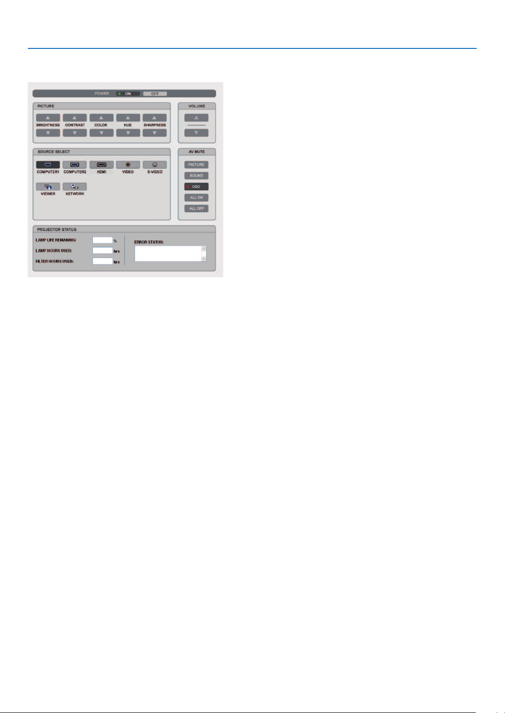
50
4. Convenient Features
Structure of the HTTP Server
POWER: This controls the power of the projector.
ON .....................................Power is switched on.
OFF ...................................Power is switched off.
VOLUME: This controls the volume of the projector.
▲ .....................................Increases the volume adjustment value.
▼ .....................................Decreases the volume adjustment value.
AV-MUTE: This controls the mute function of the projector.
PICTURE ON ....................Mutes the video.
PICTURE OFF ..................Cancels the video muting.
SOUND ON .......................Mutes the audio.
SOUND OFF .....................Cancels the audio muting.
OSD ON ............................Mutes the on-screen display.
OSD OFF ..........................Cancels the muting of the on-screen display.
ALL ON .............................Mutes each of the video, audio, and on-screen display functions.
ALL OFF ............................Cancels the muting of each of the video, audio, and on-screen display functions.
PICTURE: Controls the video adjustment of the projector.
BRIGHTNESS ▲ .............Increases the brightness adjustment value.
BRIGHTNESS ▼ ..............Decreases the brightness adjustment value.
CONTRAST ▲ .................Increases the contrast adjustment value.
CONTRAST ▼ .................Decreases the contrast adjustment value.
COLOR ▲ ........................Increases the color adjustment value.
COLOR ▼ ........................Decreases the color adjustment value.
HUE ▲ ..............................Increases the hue adjustment value.
HUE ▼ ..............................Decreases the hue adjustment value.
SHARPNESS ▲ ...............Increases the sharpness adjustment value.
SHARPNESS ▼ ...............Decreases the sharpness adjustment value.
•
The functions that can be controlled will vary depending on the signal being input to the projector. (→ page
77)

51
4. Convenient Features
SOURCE SELECT: This switches the input connector of the projector.
COMPUTER1 ....................Switches to the COMPUTER1 IN connector.
COMPUTER2 ....................Switches to the COMPUTER2 IN connector.
HDMI .................................Switches to the HDMI IN connector.
VIDEO ...............................Switches to the VIDEO IN connector.
S-VIDEO ............................Switches to the S-VIDEO IN connector.
VIEWER ............................Switches to the data on the USB memory device.
NETWORK ........................Switches to a LAN signal.
PROJECTOR STATUS: This displays the condition of the projector.
LAMP LIFE REMAINING
....Displays the remaining life of the lamp as a percentage.
LAMP HOURS USED ......Displays how many hours the lamp has been used.
FILTER HOURS USED ....Displays how many hours the lter has been used.
ERROR STATUS ..............Displays the status of errors occurring within the projector.
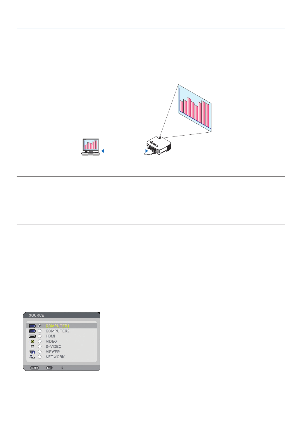
52
4. Convenient Features
⓭
Projecting Your Computer’s Screen Image from the Projector
via a Network [NETWORK PROJECTOR]
A Windows Vista-based computer can be operated using the projector over a network. The projector supports the
Network Projector function and the Remote Desktop function of Windows Vista.
By selecting the projector connected to the same network as that of your PC, the PC screen image can be pro-
jected to the screen via network. There is no need of connection using the VGA signal cable.
The projector supports the Network Projector function and the Remote Desktop function of Windows Vista.
Operation Environment
Applicable OS Windows Vista (32-bit version) Home Premium
Windows Vista (32-bit version) Business
Windows Vista (32-bit version) Ultimate
Windows Vista (32-bit version) Enterprise
(Note) These functions are not available on Windows Vista Home Basic.
Hardware speci cations The speci cations recommended by Microsoft as the operation environment for
Windows Vista should be satis ed.
Network Environment Wired LAN environment that supports TCP/IP is required.
Screen color High Color (16 bits)
True Color (24 bits and 32 bits)
* Setting with 256 colors or less is not available.
Setting the Projector to Network Projector Input Mode
1. With the projector turned on, press the SOURCE button.
The input selection window appears.
Another way to display the input selection window is to press the NETWORK button on the remote control. The
NETWORK screen will be displayed. Go to step 3.
VIDEO IN
AUDIO
I
N
USB
LA
N
AUDIO
IN
HDMI I
N
AUDIO IN
COMPUTER /
COMPONENT 2 IN
COMPUTER
/
COMPONENT 1 IN
PC CONTRO
L
MONITOR OUT
AUDIO OUT
S-VIDEO I
N
AUDIO I
N
L/MON
O
L/MON
O
R
R
AC IN
U
S
B
L
A
MP
S
TA
TUS
SOURCE
AUTO ADJUST
3D REFORM
SELECT
(
LAN
)
USB
WIRELESS
WIRELESS
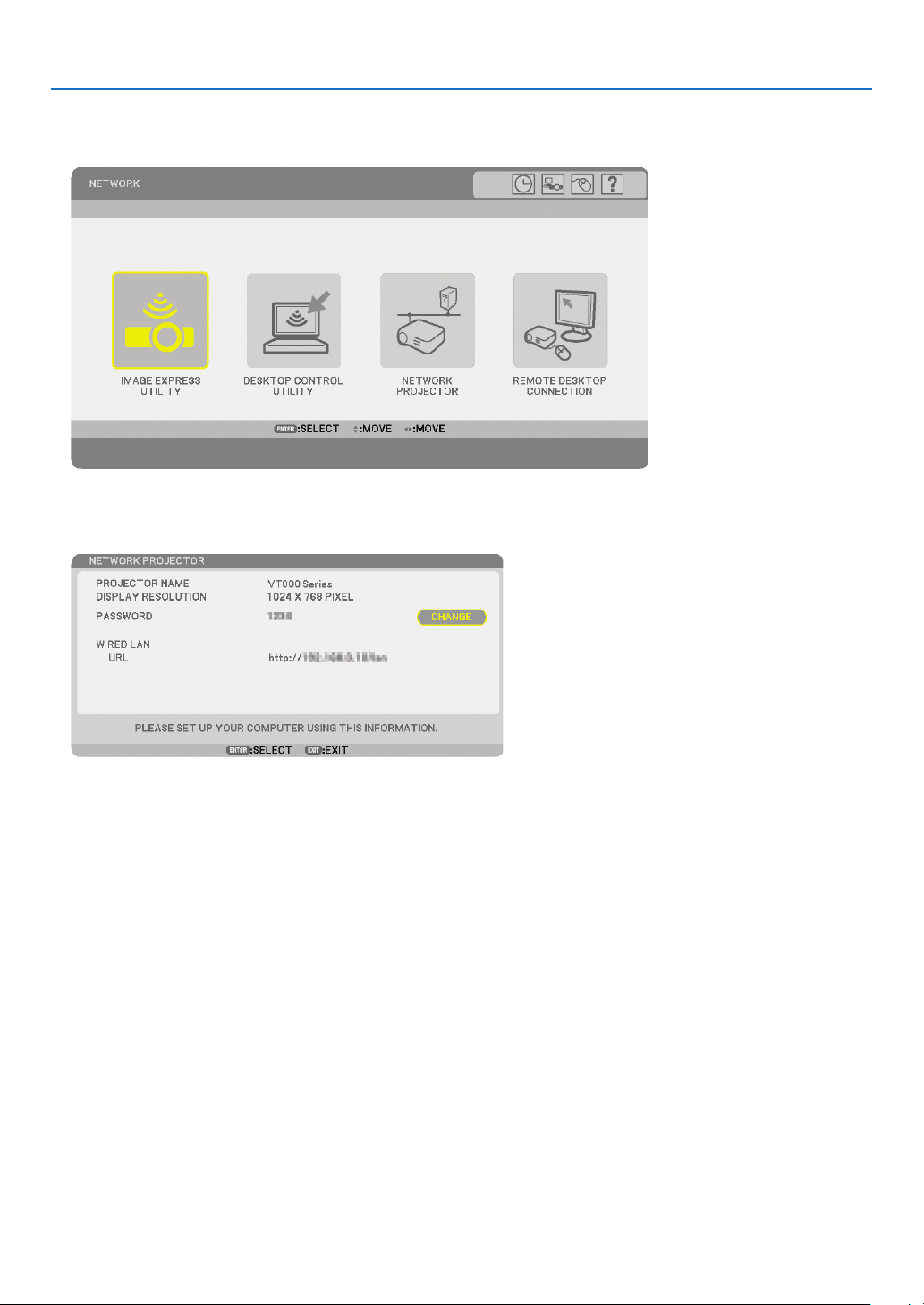
53
4. Convenient Features
2. Press the SELECT ▼ or ▲ button to select [NETWORK] and press the ENTER button.
In the screen, the [NETWORK] menu is displayed.
3. From the [NETWORK] menu, select [NETWORK PROJECTOR].
The [PROJECTOR NAME/DISPLAY RESOLUTION/PASSWORD/URL] will be displayed.
TIP:
• To change the default password “1234”, select [CHANGE] and press the ENTER button.
The [ENTER PASSWORD] screen will be displayed, Enter a numeric password. The password must be eight characters or less.
The changed password stored in the projector will be displayed in the [NETWORK PROJECTOR] screen next time.
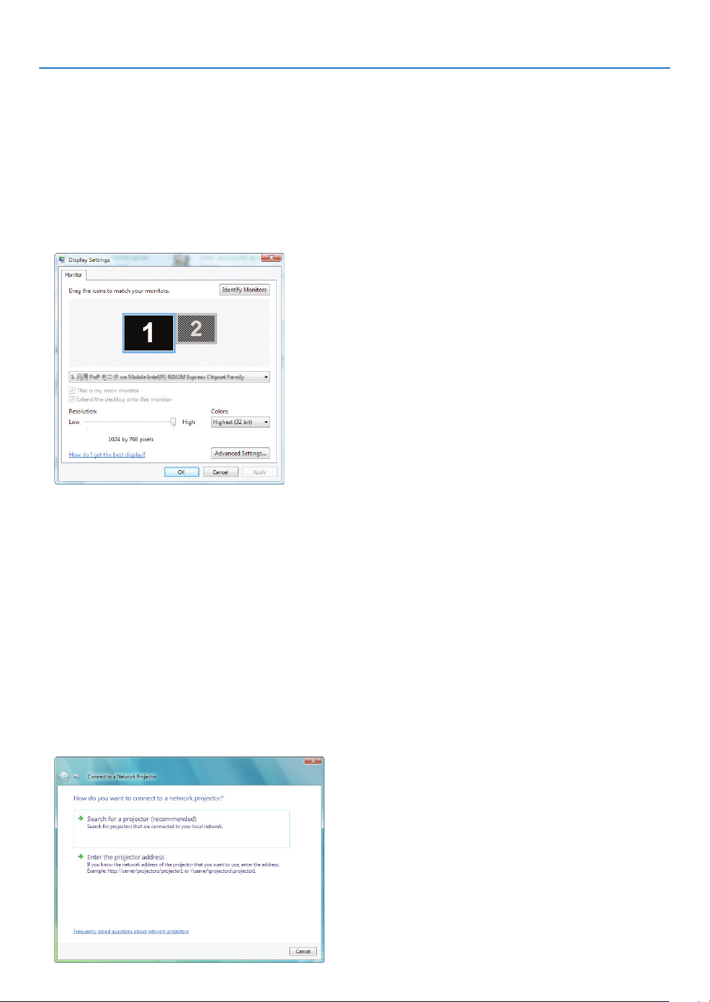
54
4. Convenient Features
Changing the resolution of Windows Vista screen to the information on [DISPLAY RESOLUTION]
in the NETWORK PROJECTOR screen.
• When using Windows Vista Service Pack 1(SP1), skip the following steps and go on to "Projecting the Image
with Network Projector" below.
1. Click [Start] from the desktop of Windows Vista.
2. Click [Control Panel].
3. Click [Adjust screen resolution] displayed under [Appearance and Personalization].
4. Operate [Resolution] slide bar to change the resolution to the resolution displayed on [DISPLAY RESO-
LUTION] in the NETWORK PROJECTOR screen.
5. Click [OK].
The message “Do you keep this screen setting?” is displayed.
6. Click [Yes].
The resolution of Windows Vista screen is changed to the resolution displayed on [DISPLAY RESOLUTION] in
the NETWORK PROJECTOR screen.
Projecting the Image with Network Projector
1. Click [Start] from the desktop of Windows Vista.
2. Click [All Programs].
3. Click [Accessories].
4. Click [Connect to a Network Projector].
When the [Permission Connect to a Network Projector] window appears,click [Yes.].
The “Connect to a Network Projector” window appears.
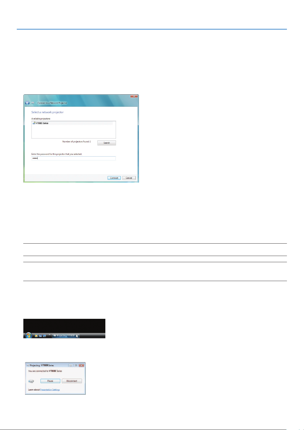
55
4. Convenient Features
5. Click [→ Search for a projector (recommended)].
In the “Available projectors” box, your projector model name is displayed.
6. Click your projector model name.
The message “Enter the password for the projector that you selected.” is displayed at the bottom of the win-
dow.
7. Check the password displayed in the screen projected by the projector.
8. Input the password displayed by the operation at Step 3 on page 53.
9. Click [Connect].
The network projector function works and the screen of Windows Vista is projected from the projector.
• On Windows Vista Service Pack 1(SP1), if the resolution of Windows Vista screen is different from the
projector's screen resolution, changing the resolution of Windows Vista will display a message for prompt-
ing the user to change the resolution of Windows Vista screen. Selecting [Yes] will change the resolution of
Windows Vista screen and proceed to the step of operating the network projector. Selecting [No] will can-
cel operating the network projector.
NOTE: When the network projector function works, the background color of the desktop changes to black. When the network
projector function is stopped, the original background color is restored.
Reference: If the projector cannot be found at Step 5, click [ → Enter the projector address]. Then, input the “Network ad-
dress” (Input example: http://10.32.97.61/lan) and “Projectorpassword” (Input example: 82291627) displayed in the screen
projected from the projector.
Exiting the Network Projector Operation
1. Click [Projecting: your projector model name] in the Windows Vista task bar.
2. Click [Disconnect].
The Network Projector function is stopped.
3. Press the MENU button of the projector to display the menu. From the menu, select an input terminal
other than [NETWORK].
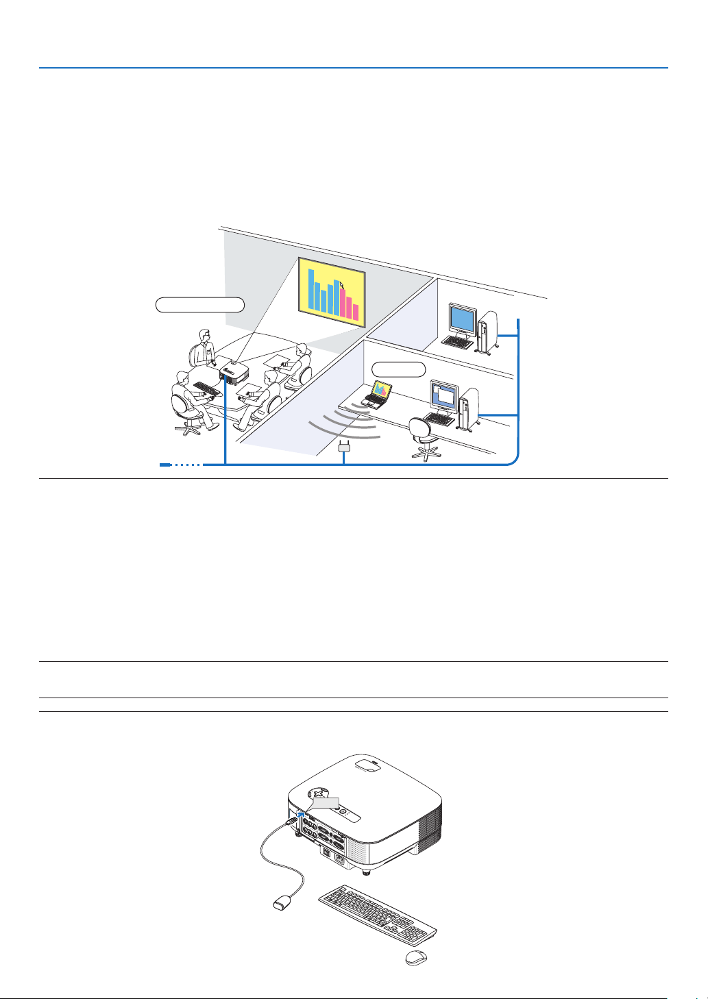
56
4. Convenient Features
⓮
Using the Projector to Operate Your Computer via a Network
[REMOTE DESKTOP]
• By selecting the PC connected to the same network as that of the projector, the PC screen image can be pro-
jected to the screen via network.
Then, by operating the keyboard connected to the projector, you can operate Windows Vista on the PC con-
nected with the network.
• With the Remote Desktop function, you can remotely operate the PC placed at a distance from the projector.
NOTE:
• Available versions of Windows Vista are provided on page
52. Windows Vista Home Premium is not available for REMOTE
DESKTOP.
• In this user’s manual this feature is described using Windows Vista as an example, but the following Windows XP will also
work with this feature.
Windows XP Professional Service Pack 2 (SP2) or later
• A keyboard is required to use the Remote Desktop function.
• The Remote Desktop function can be operated with a keyboard only. Using a wireless mouse with a wireless keyboard is more
useful for operating.
Use a commercially available wireless keyboard, a wireless mouse, and a USB wireless receiver.
Use a commercially available USB keyboard and USB mouse.
• A USB keyboard with a built-in USB hub cannot be used with the projector.
• A wireless keyboard or mouse that supports Bluetooth cannot be used with the projector.
Prepare a commercially available wireless keyboard (US layout version).
NOTE: We do not warrant that the USB port of the projector will support all USB keyboards in the market.
Connect the USB wireless receiver to the USB port (Type A) of the projector. Make all necessary settings for your
wireless keyboard and mouse.
VIDEO IN
AUDIO IN
USB
LAN
AUDIO IN
HDMI IN
AUDIO IN
COMPUTER /
COMPONENT 2 IN
COMPUTER /
COMPONENT 1 IN
PC CONTROL
MONITOR OUT
AUDIO OUT
S-VIDEO IN
AUDIO IN
L/MONO
L/MONO
R
R
AC IN
USB
LAMP
S
TATUS
SOURCE
AUTO ADJUST
3D R
EFOR
M
SELECT
USB
Meeting room
Office
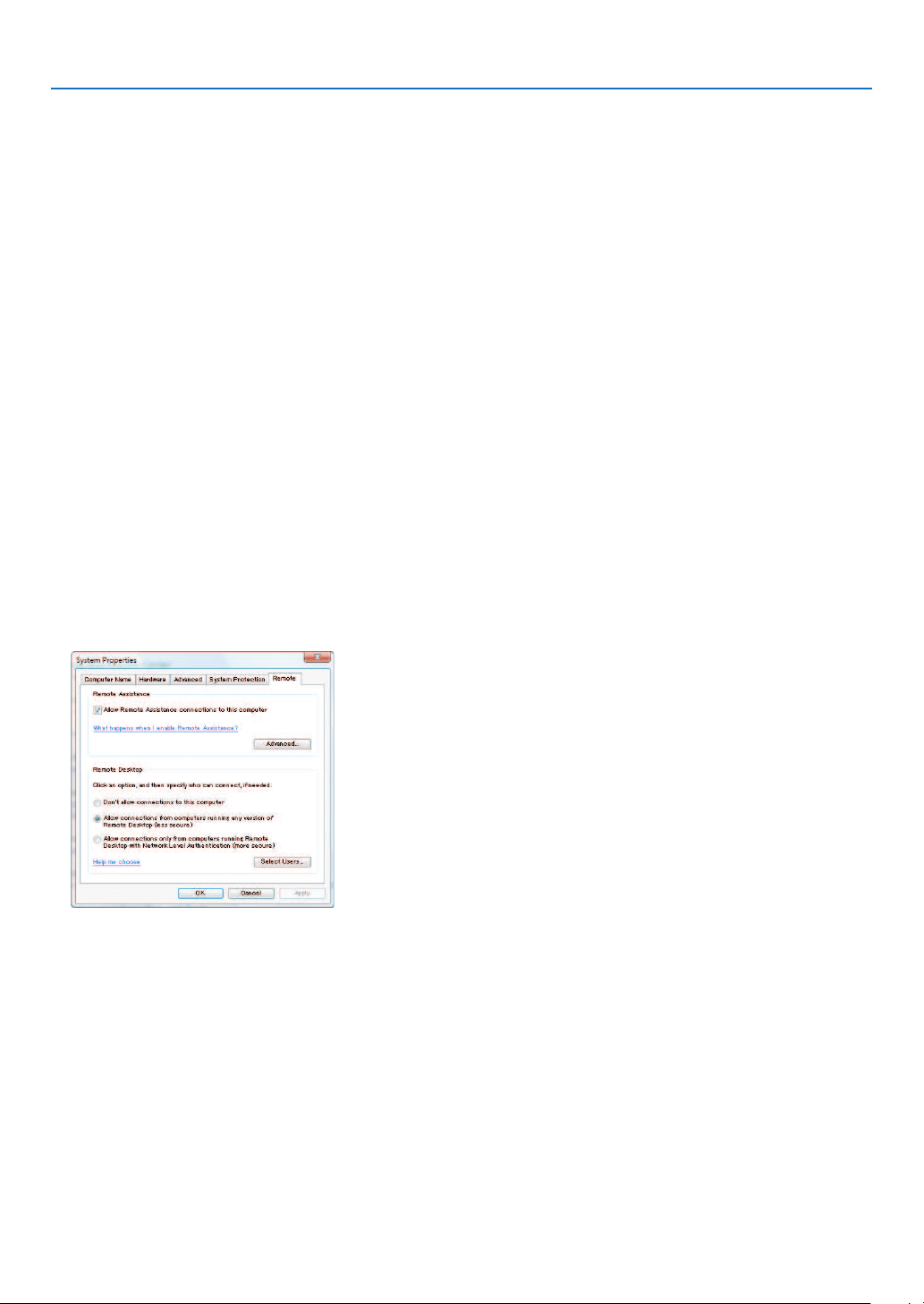
57
4. Convenient Features
Setting the password to the user account of Windows Vista
TIP: If a password has been set for an account, the steps 1 to 9 can be skipped.
1. Click [Start] from the desktop of Windows Vista.
2. Click [Control Panel].
3. Click [Add or remove user accounts] displayed under [User Accounts].
4. When the [User Account Control] confirmation window appears, click [Continue].
5. Click [Administrator].
6. Click [Create a password].
7. Input the password to the [New password] box.
8. Input the same password as that at Step 7 to the [Confirm new password] box.
9. Click [Create a password].
The Administrator is changed to [Password Protection].
Setting the Remote Access
1. Click [Start] from the desktop of Windows Vista.
2. Click [Control Panel].
3. Click [System and Maintenance].
4. Click [Allow remote access] displayed under [System].
5. When the [User Account Control] confirmation window appears, click [Continue].
The [System Properties] window appears.
6. Click [Allow connections from computers running any version of Remote Desktop (less secure)] in the
Remote Desktop box and click [OK].
Checking the IP address on Windows Vista
1. Click [Start] from the desktop of Windows Vista.
2. Click [Control Panel].
3. Click [View network status and tasks] displayed under [Network and Internet].
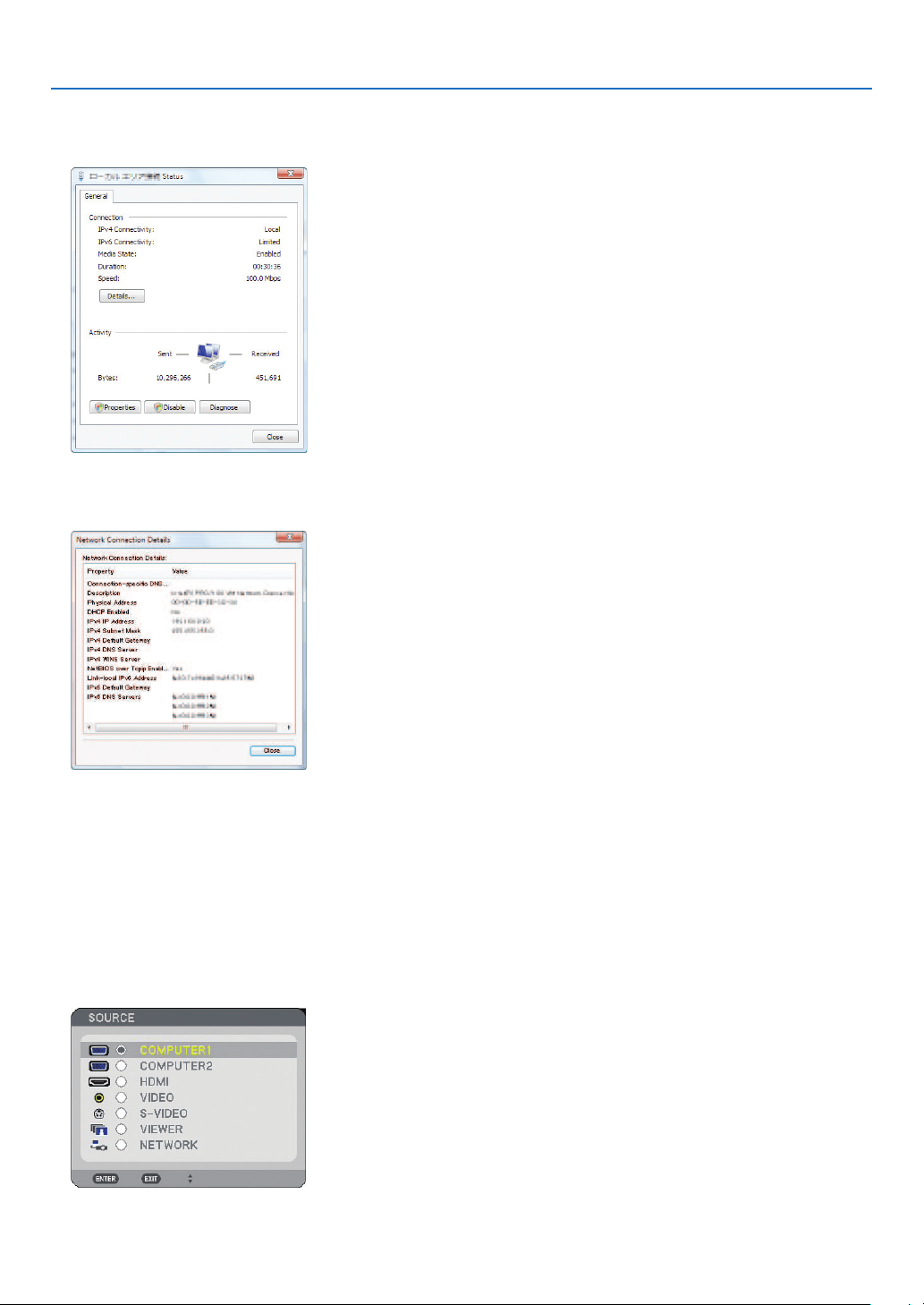
58
4. Convenient Features
4. Click [View status] displayed in blue on the right of [Local Area Connection] in the window.
The [Local Area Connection Status] window appears.
5. Click [Details...].
Write down the value for “IPv4 IP Address” (xxx.xxx.xxx.xxx) displayed.
6. Click [Close].
7. Click [X] at the upper right of the window.
The system goes back to the desktop.
Starting the Remote Desktop
1. With the projector turned on, press the SOURCE button.
The input selection window appears.
Another way to display the input selection window is to press the NETWORK button on the remote control. The
NETWORK screen will be displayed. Go to step 3.
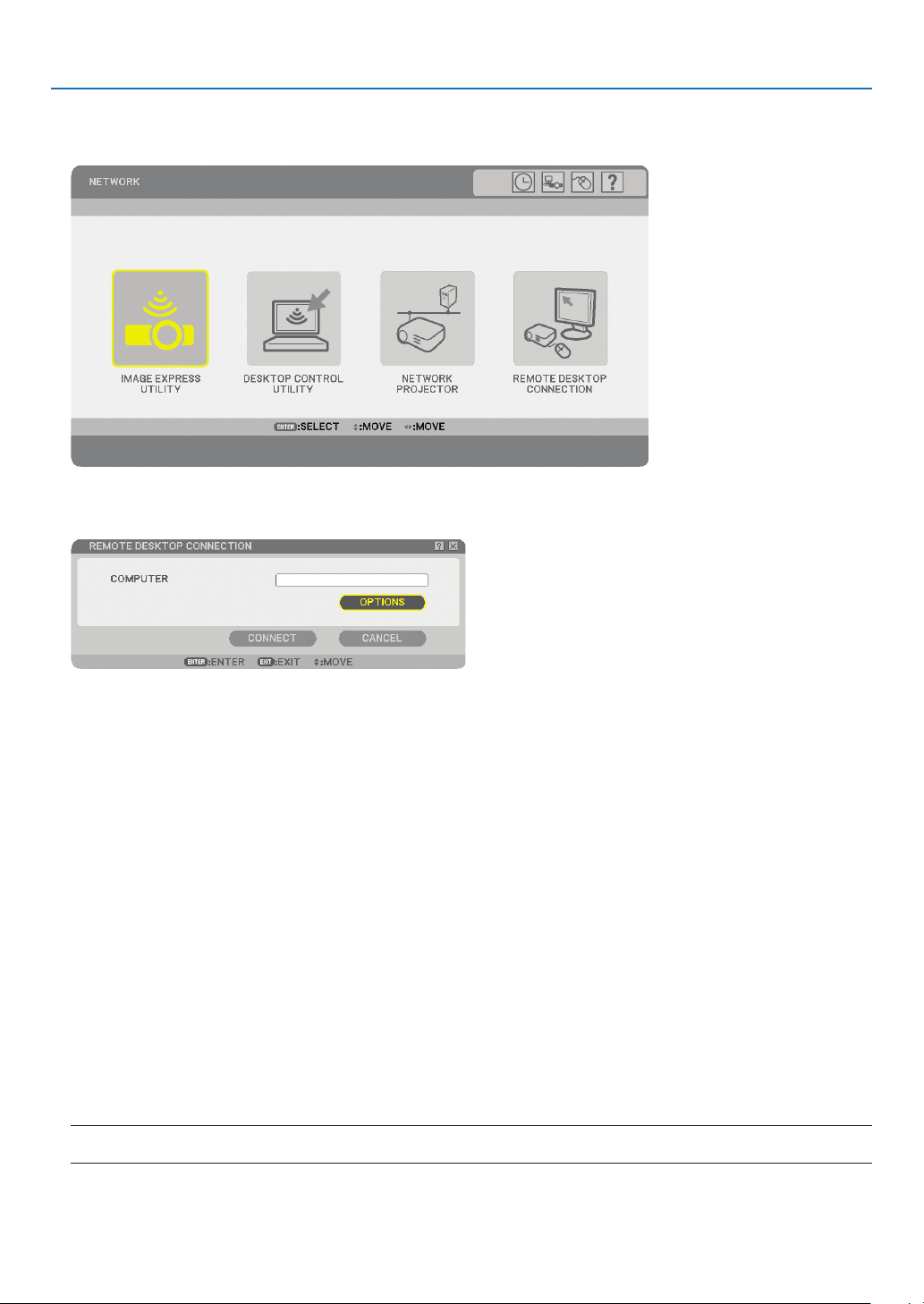
59
4. Convenient Features
2. Press the SELECT ▼ or ▲ button to select [NETWORK] and press the ENTER button.
The [NETWORK] menu will be displayed.
3. From the [NETWORK] menu, use the wireless keyboard to select [REMOTE DESKTOP CONNECTION].
The [REMOTE DESKTOP CONNECTION] window appears.
TIP:
Setting [OPTIONS] in REMOTE DESKTOP
Clicking [OPTIONS] displays the [PERFORMANCE] screen.
Making settings to [OPTIONS] will allow you to display the desktop background, or to enable the window animation function
during the Remote Desktop operation. However, doing this will cause the display’s or mouse’s response to slow down.
If the display’s or mouse’s response is slowed down, try one or more of the following:
DESKTOP BACKGROUND: Clear the check mark to display the desktop background in monochrome.
MENU AND WINDOW ANIMATION: Clear the check mark to disable menu and window animation.
THEMES: Clear the check mark not to use Themes.
SHOW CONTENTS OF WINDOW WHILE DRAGGING: Clear the check mark to show only the window pane
while dragging.
4. Operate the wireless keyboard to input the IP address of Windows Vista and click [CONNECT].
The log-on screen of Windows Vista is displayed in the screen projected by the projector.
5. Operate the wireless keyboard to input the user’s password and press [ENTER].
The remote desktop function is started.
Windows Vista desktop is displayed in the screen projected by the projector.
Log out the computer.
Use the wireless keyboard connected to the projector to operate Windows Vista.
NOTE: When the projection is made with the remote desktop function, the background color of the desktop is changed to
black.

60
4. Convenient Features
Exiting the Remote Desktop
1. Operate the keyboard to click [Start] from the desktop screen projected by the projector.
2. Click [X] on the right of the start menu.
The remote desktop function is stopped.
3. Press the SOURCE button of the projector to select an input terminal other than [NETWORk].
When using the remote control, press a button other than the NETWORK button.

61
5. Using the Viewer
❶
Making the Most out of the Viewer Function
Features
The Viewer feature allows you to view slides stored on a USB memory on the projector. Even if no computer is
available, presentations can be conducted simply with the projector. This feature is convenient for holding presen-
tations at meetings and in of ces, as well as for playing images taken on digital cameras.
Easy to use
• Presentations can be made by inserting a USB memory (not supplied)
• Easy slide switching
• Remote control operation
• Jumping to a list of slides or any speci c slide
Simple utility software (for computer)
• Ulead Photo Explorer 8.0SE Basic operable.
• Control screen for displaying lists of slides and editing.
TIP:
• To use the Viewer, fi rst you need to create presentation materials on your PC (JPEG, BMP, GIF*
1
, PNG*
1
, Index*
2
).
For creating presentation materials using the Ulead Photo Explorer 8.0, see the On-line help in Ulead Photo Explorer 8.0.
*
1
Both PNG and GIF format support non-interlaced images only.
*
2
“Index” fi le is a fi le created using the Ulead Photo Explorer 8.0 contained on the optional NEC User Supportware 5 CD-
ROM.
NOTE:
• Use commercially available USB memory devices.
• We do not warrant that the USB port of the projector will support all USB memory devices in the market.
• The projector does not support NTFS formatted USB memory device.
Be sure to use a USB memory device formatted with the FAT32, FAT16 or FAT fi le system.
To format your USB memory device in your computer, refer to the document or help fi le that comes with your Windows.
❷
Saving data to a USB memory device
There are two ways to save your data to a USB memory device.
Using Ulead Photo Explorer 8.0 (optional)
Install Ulead Photo Explorer 8.0 from the User Supportware 5 to your computer. Use Ulead Photo Explorer 8.0 to
create graphic data on your computer and save the les to a USB memory device.
Using Windows Explorer to save fi les
Supported le format for Viewer are JPEG, BMP, PNG, GIF and Index.
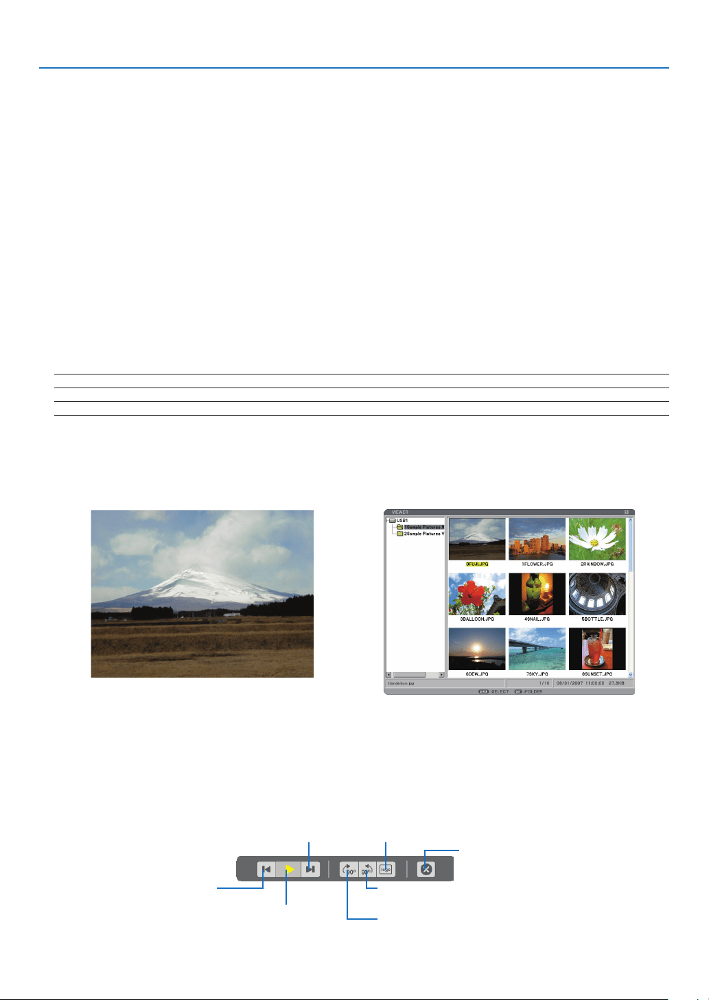
62
5. Using the Viewer
❸
Operating the Viewer Function from the Projector (playback)
This section describes the operation for showing slides created using the Viewer function with the projector. It is
also possible to make slides directly from the images projected with the projector.
Projecting slides (Viewer)
Preparation: Store JPEG or BMP les (JPEG, BMP, non-interlaced GIF or non-interlaced PNG les) in a USB
memory inserted into your PC.
To start the Viewer, press the SOURCE button on the cabinet to select [VIEWER]. (→ page
22)
Viewer screen will be displayed. (A slide will be displayed at the factory default.)
• You can use the VIEWER button on the remote control to select [VIEWER].
Operating Viewer Menu
1. Insert a USB memory into the USB port of the projector.
The USB indicator lights.
2. Press the VIEWER button on the remote control or select the [VIEWER] from the source list.
An image stored in the USB memory will be displayed.
NOTE: When [SHOW THUMBNAILS] is turned on in the OPTIONS menu, the thumbnail screen will be displayed. (→ page
64)
NOTE: Pressing the EXIT button during slide playback will display the thumbnail screen.
Slide and Thumbnail
When VIEWER is selected, one of the two screens is displayed.
One is a slide and the other is a thumbnail screen.
[SLIDE] [THUMBNAILS]
TIP: To switch from [SLIDE] to [THUMBNAILS], press the EXIT button.
The Control Bar
Pressing the MENU button during slide playback will display the control bar which allows you to operate a slide-
show. Press the EXIT button to close the control bar.
The control bar contains the following icon buttons:
Returns to the
previous image.
Plays back slides.
Stops Auto Play while you
are playing back slides.
Advances to the next image.
Rotates the image 90 degrees
clockwise.
Rotates the image 90 degrees
counterclockwise.
Selects the currently
displayed image for
your background logo.
Quits slide playback and
then returns to the thumb-
nail screen.
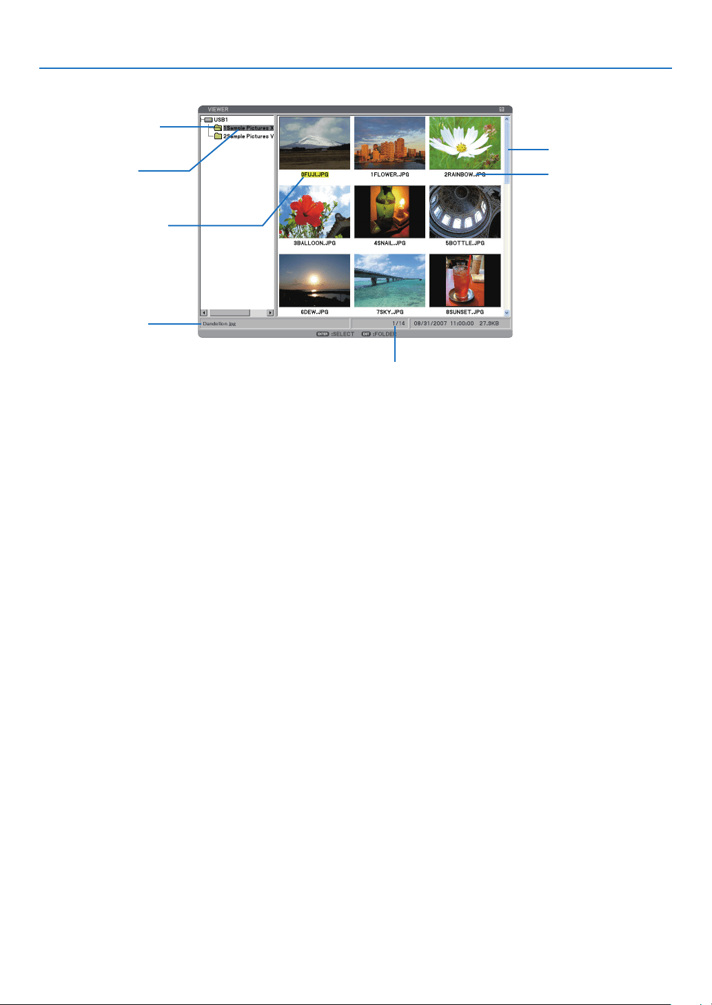
63
5. Using the Viewer
Highlight ................................... Indicates the selected folder or drive.
List of folders ...........................Indicates folders contained on a USB memory.
Information............................... Indicates information of the selected fi le or folder.
Folder: folder name, number of fi les, creation date (month/day/year), creation time (hour:min-
ute:second).
File: fi le name, slide number/number of displayable slides in a folder, creation date (month/day/
year), creation time (hour:minute:second), fi le size.
Number of fi les .........................Indicates number of displayable slides in the selected folder. The maximum number of images
recognized as slides within one directory is about 250.
Thumbnail/fi le name ................Indicates thumbnails and names contained in a folder.
Cursor .......................................Indicates the selected slide.
Scroll bar ..................................Used to view folders or fi les not visible in the window.
Highlight
List of folders
Information
Number of files
Thumbnail/file name
Scroll bar
Cursor (yellow)
Thumbnail screen
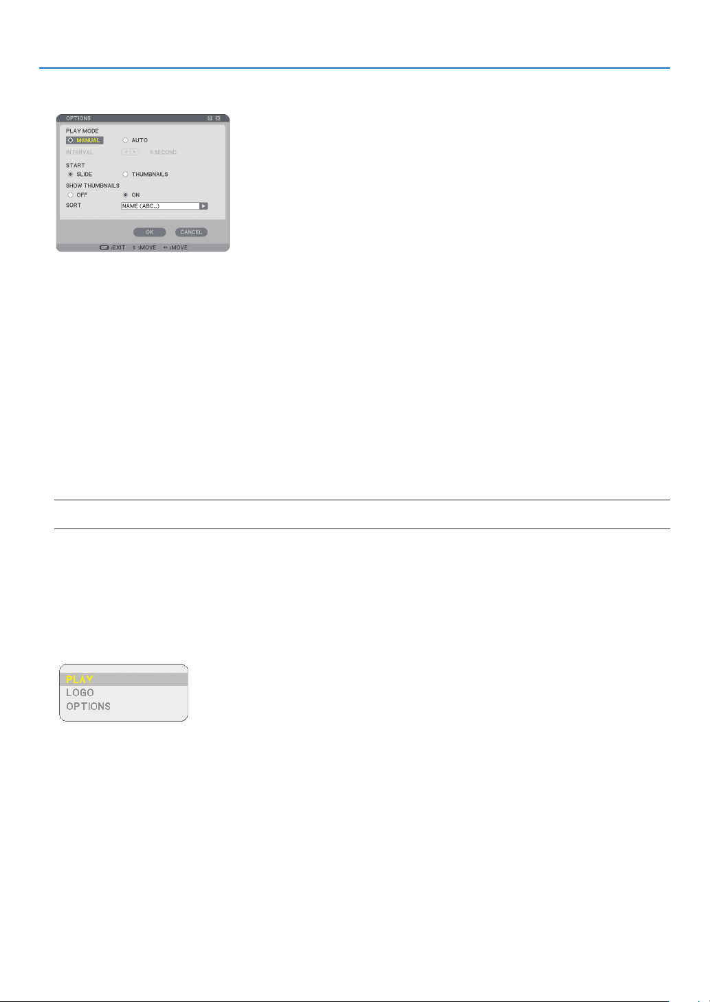
64
5. Using the Viewer
Setting Option for Viewer
PLAY MODE:
MANUAL ............... Views a slide manually when the Viewer source is selected.
AUTO ..................... Plays back slides automatically when the Viewer source is selected.
INTERVAL:
Speci es interval time between 5 and 300 seconds.
START:
Speci es start screen when the Viewer source is selected.
SHOW THUMBNAILS:
Selecting the Viewer source will display a list of thumbnails of graphic les stored in the USB memory when [ON]
is selected. Selecting the Viewer source will display a list of icons of graphic les stored in the USB memory
when [OFF] is selected.
SORT:
Rearranges the slides or thumbnails by name, extension, date or size.
NOTE: This setting is not available for the following folders:
* Folders created with the “Output Viewer” feature of Ulead Photo Explorer 8.0 or with Viewer PPT Converter 3.0
OK/CANCEL:
To close the Options menu with saving changes, select [OK] and press the ENTER button.
To close the Options menu without saving changes, select [CANCEL] and press the ENTER button.
THUMBNAILS menu
The THUMBNAILS menu will appear when you press the MENU button on the remote control or the projector
cabinet. To close the THUMBNAILS menu, press the EXIT button.
The THUMBNAILS menu includes the following commands:
PLAY .................. Plays back automatically or manually depending on the setting in Options. This allows you to move on
to the next slide when [MANUAL] is selected in the [PLAY MODE].
LOGO ................. Replace the default background logo with another logo in JPEG, BMP, non-interlaced GIF or non-inter-
laced PNG format.
OPTIONS ........... Displays the Viewer setting options.

65
5. Using the Viewer
Exiting Viewer
To exit Viewer, switch to another input such as COMPUTER1, COMPUTER2, HDMI, VIDEO, S-VIDEO or NET-
WORK.
* To switch to another input, there are two ways:
• Press the COMPUTER1, COMPUTER2, HDMI, VIDEO, S-VIDEO or NETWORK button on the remote con-
trol.
• Press the MENU button on the remote control to display the Viewer menu. Press the MENU button again to
display the main menu and select the input from the [SOURCE] submenu.
With this function it is possible to switch directly to a slide when the picture of a VCR or computer is being project-
ed.
Example: When conducting presentations using a combination of slides and moving pictures from a VCR, etc., it is
possible to switch from a Viewer slide to the video picture then back to the Viewer slide simply by using the Viewer
button.
NOTE: Even if you switch the current Viewer source to another source, the current slide is retained. When you return back to the
Viewer, you will get the slide that has been retained.
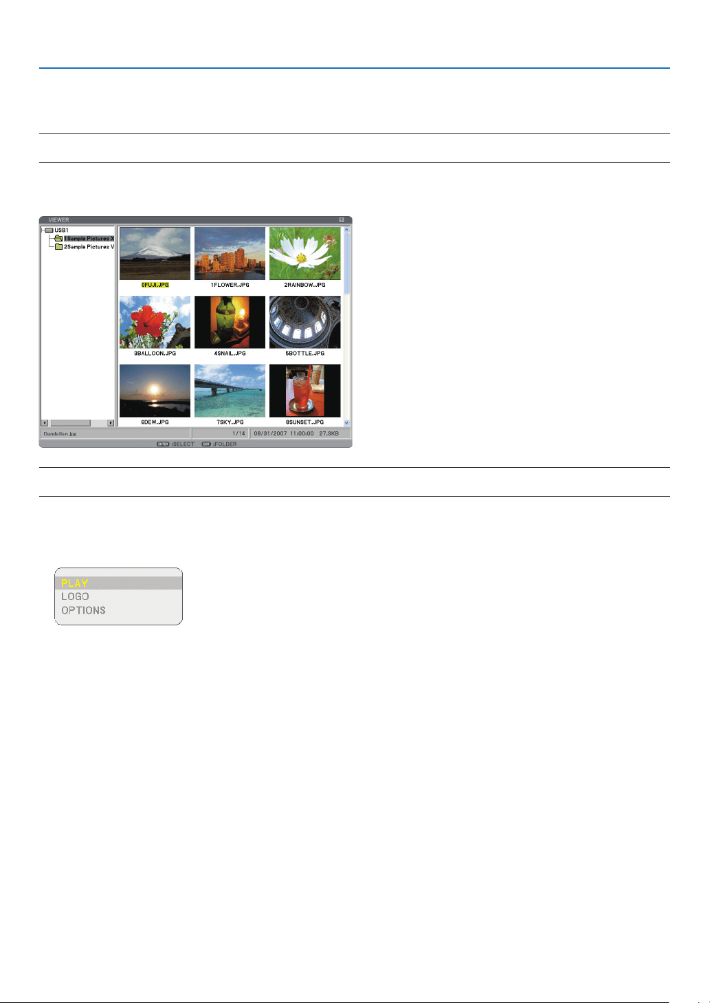
66
5. Using the Viewer
❹
Changing Background Logo
You can change the default background logo using the Viewer feature.
NOTE: File size must be 256KB or less. Maximum fi le resolution is 1024 x 768. File formats other than JPEG, BMP, non-inter-
laced GIF or non-interlaced PNG are not available.
Preparation: Store JPEG or BMP les (JPEG, BMP, non-interlaced GIF or non-interlaced PNG les) in a USB
memory into the projector’s USB port.
NOTE: To change highlight from the Thumbnails screen (right window) to a directory tree (left window) , press the EXIT button.
To return highlight to the Thumbnails screen, press the ENTER button.
1. Use the SELECT ▲▼◀ ▶ button to select a file (slide) for your background logo when displaying the
Thumbnail screen.
2. Press the MENU button to display the THUMBNAILS menu.
3. Use the SELECT ▼ button to select [LOGO] and then press the ENTER button.
A confirmation dialog box will be displayed.
4. Use the SELECT ◀ button to select [YES] and press the ENTER button. This completes changing a logo
for the background.
* Once you have changed the background from the NEC logo to another, you cannot return the logo to back-
ground even by using [RESET]. To put the NEC logo back in the background logo, repeat the above steps. The
NEC logo le is included on PC Control Utility 3.0 which is downloadable from our web site:
http://www.nec-pj.com
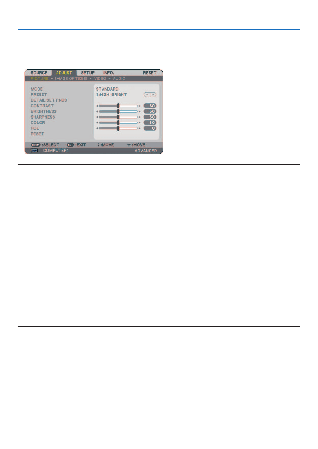
67
❶
Using the Menus
1. Press the MENU button on the remote control or the projector cabinet to display the menu.
NOTE: The commands such as ◀▶
,
ENTER, EXIT in the bottom show available buttons for your operation.
2. Press the SELECT ◀▶ buttons on the remote control or the projector cabinet to display the submenu.
3. Press the ENTER button on the remote control or the projector cabinet to highlight the top item or the
first tab.
4. Use the SELECT ▲▼ buttons on the remote control or the projector cabinet to select the item you want
to adjust or set.
You can use the SELECT ◀▶ buttons on the remote control or the projector cabinet to select the tab you
want.
5. Press the ENTER button on the remote control or the projector cabinet to display the submenu window.
6. Adjust the level or turn the selected item on or off by using the SELECT ▲▼◀ ▶ buttons on the remote
control or the projector cabinet.
Changes are stored until you adjust it again.
7. Repeat steps 2 -6 to adjust an additional item, or press the EXIT button on the remote control or the pro-
jector cabinet to quit the menu display.
NOTE: When a menu or message is displayed, several lines of information may be lost, depending on the signal or settings.
8. Press the MENU button to close the menu.
To return to the previous menu, press the EXIT button.
6. Using On-Screen Menu
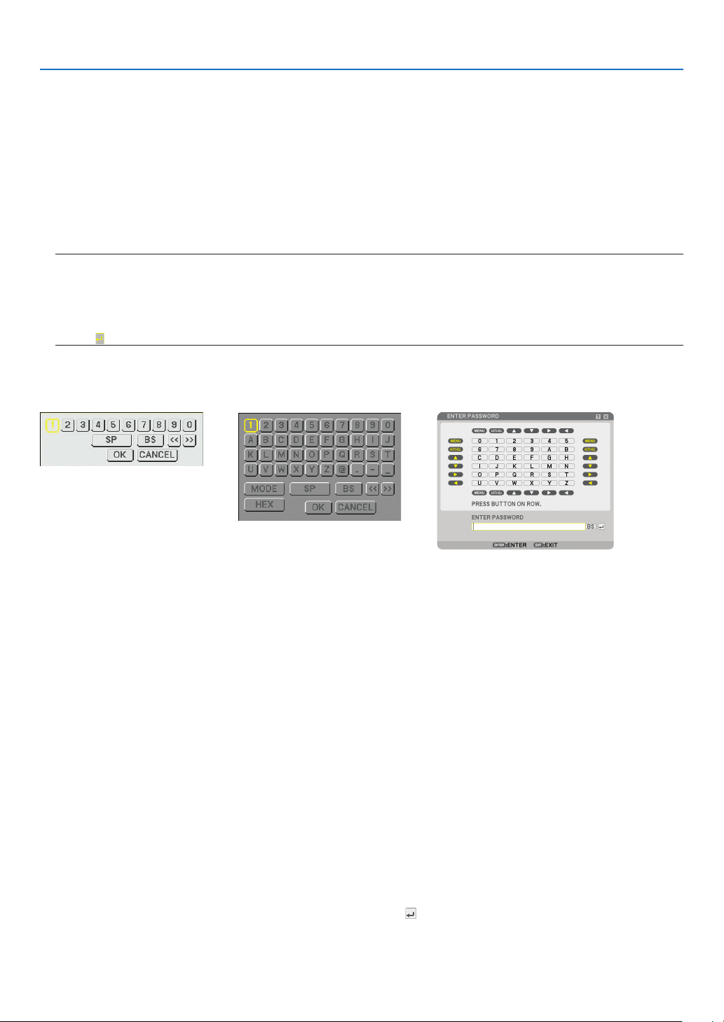
68
6. Using On-Screen Menu
Using ADVANCED menu and BASIC menu
The projector has two menu modes: the ADVANCED menu and the BASIC menu.
ADVANCED menu .. This is the menu that contains all the available menus and commands. Users with an ADMINISTRAOR
or ADVANCED account can access the ADVANCED menu.
BASIC menu .......... This is the basic menu that contains minimum essentials of menus and commands. Users with a BA-
SIC account can access the BASIC menu.
See page
47 for settings available to ADVANCED and BASIC menus.
NOTE:
• A user with an ADMINISTRATOR account that has no password set is registered at the factory.
This will allow the user to access the ACCOUNT items without password entry.
• When using your USB mouse, click each number or alphabet.
BS: Delete the character before the cursor or highlight.
OK/[
]
: Confi rm the password and close the Software keyboard.
Entering alphanumeric characters by using Software Keyboard
[IP ADDRESS, PASSWORD] [USER NAME, PROJECTOR NAME] [PASSWORD OR KEYWORD]
1 to 0 and Characters
.............................. Use to type in password or key-
word.
MODE .................... Selects one of three modes for
numbers, alphabet and special
characters.
SP .......................... Inserts a space
BS .......................... Deletes one character backward
<< ......................... Returns to the previous
>> ......................... Advances to the next
OK.......................... Executes the selection
CANCEL ................. Cancels the selection
When using the remote control:
1. Press the MENU, AUTO ADJ, SELECT ▲, SE-
LECT ▼, SELECT ▶ or SELECT ◀ button to se-
lect a character in the row.
Example: To enter “C”, press the SELECT ▲ but-
ton.
2. Press the MENU, AUTO ADJ, SELECT ▲, SE-
LECT ▼, SELECT ▶ or SELECT ◀ button to se-
lect a character in the column.
Example: To enter “C”, press the MENU button.
EXIT ....................... Deletes a character.
ENTER ................... Makes your input take effect and
closes the input screen.
When using the mouse:
Point to a character and click it.
[BS] ....................... Deletes a character.
[
] ........................ Makes your input take effect and
closes the input screen.
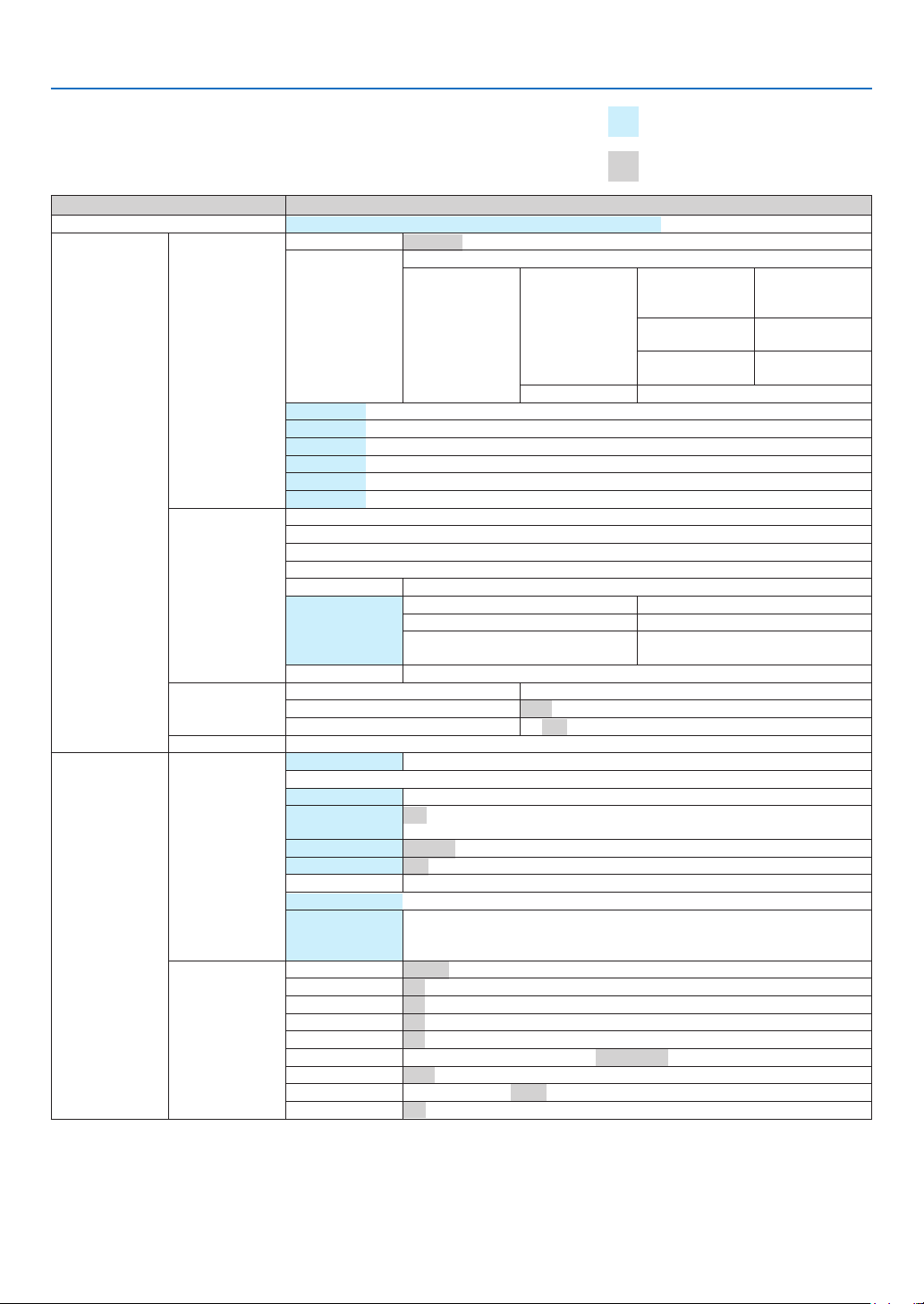
69
6. Using On-Screen Menu
Menu tree
Basic menu items are indicated by
shaded area.
Factory default settings are indi-
cated by the gray shaded area.
Menu Item
Source COMPUTER1, COMPUTER2, HDMI, VIDEO, S-VIDEO, VIEWER, NETWORK, ENTRY LIST
ADJUST
PICTURE
MODE STANDARD, PROFESSIONAL
PRESET
1 to 6
DETAIL SETTINGS
GENERAL
REFERENCE
HIGH-BRIGHT, PRESEN-
TATION, VIDEO, MOVIE,
GRAPHIC, sRGB
GAMMA CORREC-
TION
DYNAMIC, NATURAL,
BLACK DETAIL
COLOR TEMPERA-
TURE
5000, 6500, 7800,
8500, 9300, 10500
WHITE BALANCE CONTRAST RGB, BRIGHTNESS RGB
CONTRAST
BRIGHTNESS
SHARPNESS
COLOR
HUE
RESET
IMAGE OPTIONS
CLOCK
PHASE
HORIZONTAL POSITION
VERTICAL POSITION
OVERSCAN 0%, 5%, 10%
ASPECT RATIO
RGB 5:4, 4:3, 16:9, 16:10, 15:9
4:3 SCREEN (COMPONENT)/VIDEO/S-VIDEO 4:3, LETTERBOX, WIDE SCREEN, ZOOM
WIDE SCREEN (COMPONENT)/VIDEO/
S-VIDEO
4:3 WINDOW, LETTERBOX, WIDE SCREEN,
4:3 FILL
RESOLUTION AUTO, NATIVE
VIDEO
NOISE REDUCTION RANDOM NR, MOSQUITO NR, BLOCK NR
DEINTERLACE AUTO, VIDEO, FILM
3D Y/C SEPARATION OFF, ON
AUDIO VOLUME, BASS, TREBLE, BALANCE, 3D SURROUND (OFF, ON)
SETUP
BASIC
KEYSTONE AUTO KEYSTONE, HORIZONTAL, VERTICAL
CORNERSTONE
PIP/SIDE BY SIDE MODE, POSITION, SOURCE
WALL COLOR
OFF, BLACKBOARD, BLACKBOARD (GRAY), LIGHT YELLOW, LIGHT GREEN, LIGHT BLUE,
SKY BLUE, LIGHT ROSE, PINK
LAMP MODE NORMAL, ECO
OFF TIMER OFF, 0:30, 1:00, 2:00, 4:00, 8:00, 12:00, 16:00
TOOLS PROGRAM TIMER, CORNERSTONE, ENTRY LIST, [DATE, TIME PRESET], [MOUSE], [HELP]
LOGOFF
LANGUAGE
ENGLISH, DEUTSCH, FRANÇAIS, ITALIANO, ESPAÑOL, SVENSKA, 日本語 , DANSK,
PORTUGUÊS, ČEŠTINA, MAGYAR, POLSKI, NEDERLANDS, SUOMI, NORSK,
TÜRKÇE, РУССКИЙ , عربي, ΕΛΛΗΝΙΚΑ , 中文 , 한국어
MENU
COLOR SELECT COLOR, MONOCHROME
SOURCE DISPLAY ON, OFF
MESSAGE DISPLAY ON, OFF
TIME DISPLAY ON, OFF
ID DISPLAY ON, OFF
MENU DISPLAY TIME MANUAL, AUTO 5 SEC, AUTO 15 SEC, AUTO 45 SEC
BACKGROUND BLUE, BLACK, LOGO
FILTER MESSAGE OFF, 100[H], 200[H], 500[H], 1000[H]
CLOSED CAPTION OFF, CAPTION 1-4, TEXT 1-4
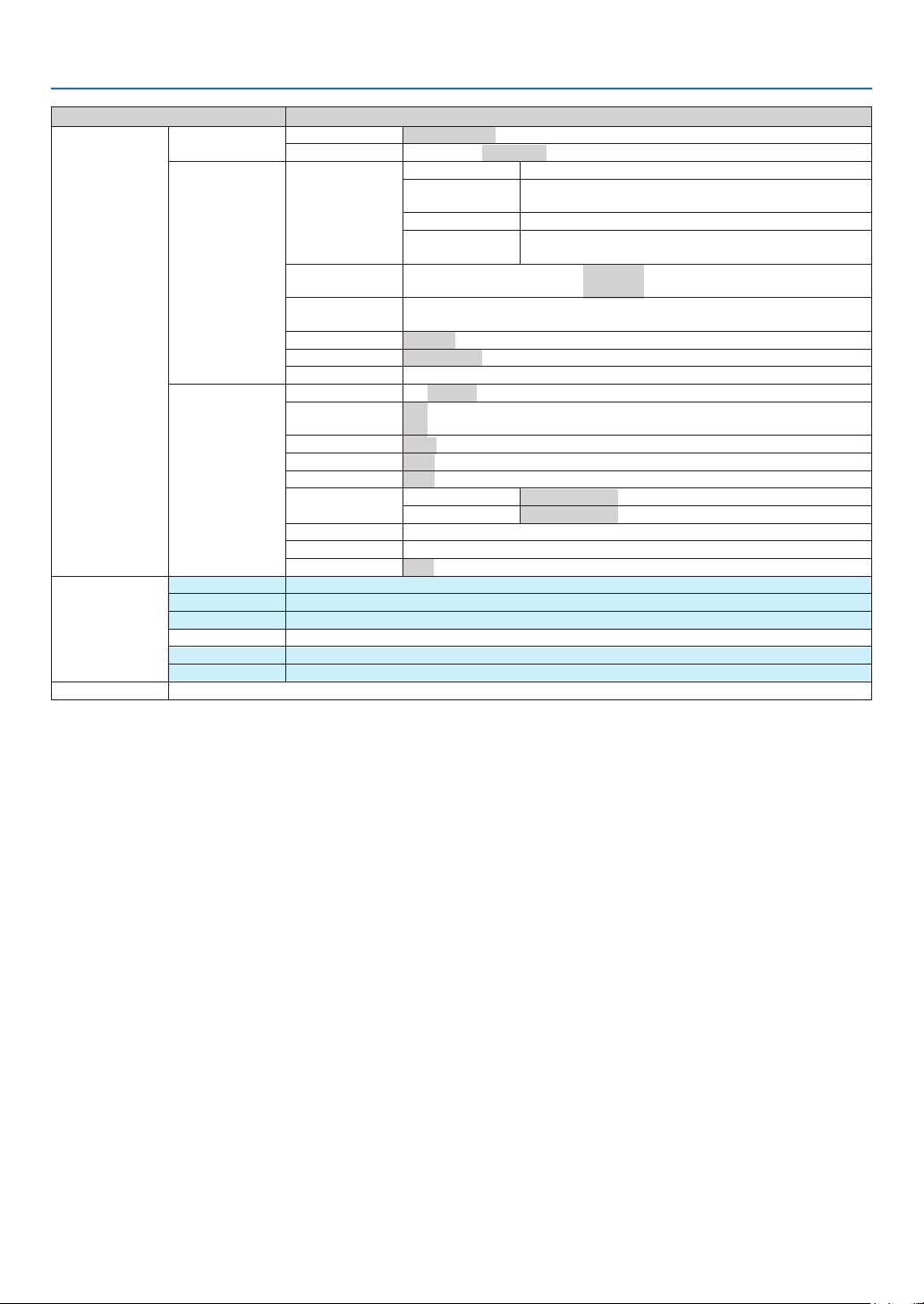
70
6. Using On-Screen Menu
Menu Item
SETUP
INSTALLATION(1)
ORIENTATION DESKTOP FRONT, CEILING REAR, DESKTOP REAR, CEILING FRONT
SCREEN SCREEN TYPE: 4:3 SCREEN, WIDE SCREEN / POSITION
INSTALLATION(2)
NETWORK SETTINGS
GENERAL: PROJECTOR NAME, WIRED LAN
WIRED:
PROFILES, DHCP, IP ADDRESS, SUBNET MASK, GATEWAY,
DNS CONFIGURATION, RECONNECT
DOMAIN: HOST NAME, DOMAIN NAME
MAIL:
ALERT MAIL, SENDER’S ADDRESS, SMTP SERVER NAME
RECIPIENT’S ADDRESS 1-3, TEST MAIL
COMMUNICATION
SPEED
4800 BPS, 9600 BPS, 19200 BPS, 38400 BPS
SECURITY SETTINGS
CONTROL PANEL LOCK, BACKGROUND LOCK, ACCOUNT LOCK, ACCOUNT, SECURITY,
PJLINK
STANDBY MODE NORMAL / POWER-SAVING
REMOTE SENSOR FRONT / BACK, FRONT, BACK
CONTROL ID CONTROL ID NUMBER, CONTROL ID
OPTIONS
AUTO ADJUST OFF, NORMAL, FINE
AUTO POWER ON
(AC)
OFF, ON
AUTO POWER OFF OFF, 0:05, 0:10, 0:20, 0:30
FAN MODE AUTO, HIGH, HIGH ALTITUDE
DEFAULT SOURCE SELECT
LAST, AUTO, COMPUTER1, COMPUTER2, HDMI, VIDEO, S-VIDEO, VIEWER, NETWORK
SIGNAL SELECT
COMPUTER1 RGB/COMPONENT, RGB, COMPONENT
COMPUTER2 RGB/COMPONENT, RGB, COMPONENT
COLOR SYSTEM VIDEO, S-VIDEO
HDMI SETTINGS VIDEO LEVEL, AUDIO SELECT
OUT TERMINAL LAST, COMPUTER1, COMPUTER2
INFO.
USAGE TIME
LAMP LIFE REMAINING, LAMP HOURS USED, FILTER HOURS USED
SOURCE(1) INPUT TERMINAL, SIGNAL TYPE, VIDEO TYPE, SOURCE NAME, ENTRY NO.
SOURCE(2) HORIZONTAL FREQUENCY, VERTICAL FREQUENCY, SYNC TYPE, SYNC POLARITY, SCAN TYPE
WIRED LAN IP ADDRESS, SUBNET MASK, GATEWAY, MAC ADDRESS
VERSION(1) PRODUCT, SERIAL NUMBER
VERSION(2) FIRMWARE, DATA, FIRMWARE2, DATA2
RESET CURRENT SIGNAL, ALL DATA, ALL DATA (INCLUDING ENTRY LIST), CLEAR LAMP HOURS, CLEAR FILTER HOURS
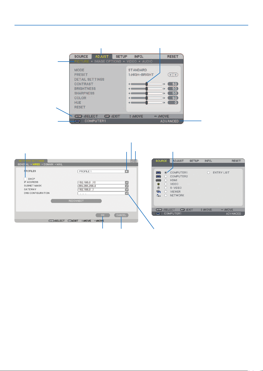
71
6. Using On-Screen Menu
Menu Elements
Slide bar
Solid triangle
Highlight
Tab
Radio button
Check box
Cancel button
OK button
Menu windows or dialog boxes typically have the following elements:
Highlight ................ Indicates the selected menu or item.
Solid triangle ......... Indicates further choices are available. A highlighted triangle indicates the item is active.
Tab ......................... Indicates a group of features in a dialog box. Selecting on any tab brings its page to the front.
Radio button ......... Use this round button to select an option in a dialog box.
Check box .............. Place a check mark in the square box to turn the option On.
Slide bar ................ Indicates settings or the direction of adjustment.
OK button .............. Press to confi rm your setting. You will return to the previous menu.
Cancel button ........ Press to cancel your setting. You will return to the previous menu.
Close button .......... Click to close the window and saving changes (USB mouse only).
Help button ........... Indicates that help about that feature is available (USB mouse only). Press the HELP button on the re-
mote control to display help.
Return symbol ...... Indicates the software keyboard is available.
Help button
Close button
Currently se-
lected source
Available buttons
Currently se-
lected user
Return symbol
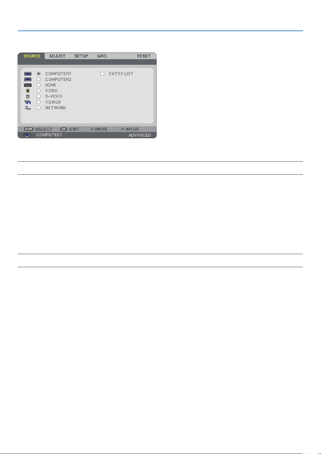
72
6. Using On-Screen Menu
쐏
Menu Descriptions & Functions [SOURCE]
COMPUTER1 and 2
Selects the computer connected to your COMPUTER1 or COMPUTER2 input connector signal.
NOTE: When the component input signal is connected to the COMPUTER 1 IN/COMPONENT 1 IN or COMPUTER 2 IN/COMPO-
NENT 2 IN connector, select [COMPUTER1] or [COMPUTER2] respectively.
HDMI
Selects the HDMI compatible equipment connected to your HDMI IN connector.
VIDEO
Selects what is connected to your VIDEO input-VCR, DVD player or document camera.
S-VIDEO
Selects what is connected to your S-VIDEO input-VCR or DVD player.
NOTE: A frame may freeze for a brief period of time when a video is played back in fast-forward or fast-rewind with a Video or
S-Video source.
VIEWER
This feature enables you to make presentations using a USB memory that contains captured images and slides
created with the exclusive Ulead Photo Explorer 8.0 for NEC contained on the optional User Supportware 5 CD-
ROM. (→ page
61 “5. Using the Viewer”)
NETWORK
Selects a signal from the LAN port (RJ-45).
When a source connected on a network is not made settings, the [NETWORK] menu will be displayed.
(→ page
95)
ENTRY LIST
Displays a list of signals. (→ page
73)
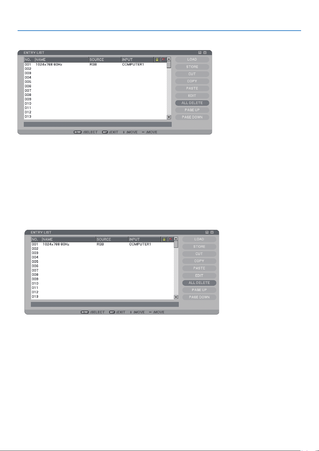
73
6. Using On-Screen Menu
[ENTRY LIST]
Using the Entry List
When any source adjustments are made, the adjustments are automatically registered in the Entry List. The (ad-
justment values of) registered signals can be loaded from the Entry List whenever necessary.
However, only up to 100 patterns can be registered in the Entry List. When 100 patterns have been registered in
the Entry List, an error message is then displayed and no additional patterns can be registered. You should thus
delete (adjustment values of) signals that are no longer needed.
Entering the Currently Projected Signal into the Entry List
1. Display the Entry List.
2. Use the SELECT ▲ or ▼ button on your remote control or the projector cabinet to select any number.
3. Use the SELECT ▶ button to select [STORE] and press the ENTER button.
You can edit signals on the [ENTRY LIST].
LOAD ..................... Enables you to select a signal from the list.
STORE ................... Enables you to store the currently projected signal.
CUT ....................... Enables you to remove a selected signal from the list and place it on the “clipboard” in the projector.
COPY ..................... Enables you to copy a selected signal from the list and place it on the “clipboard” in the projector.
PASTE ................... Enables you to paste the signal placed on the “clipboard” to any other line of the list.
EDIT ....................... Enables you to change SOURCE NAME, INPUT TERMINAL, LOCK, and SKIP.
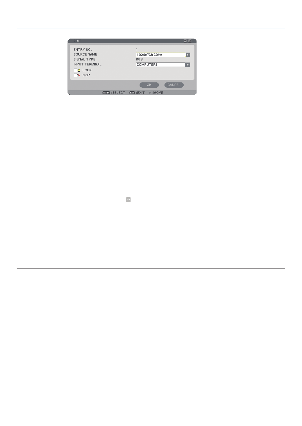
74
6. Using On-Screen Menu
SOURCE NAME:
Enter a signal name. Up to 18 alphanumeric characters can be used.
INPUT TERMINAL:
Change the input terminal.
LOCK:
Set so that the selected signal cannot be deleted when [ALL DELETE] is executed. After executing [LOCK],
the changes cannot be saved.
SKIP:
Set so that the selected signal will be skipped during auto search.
When complete, select OK and press ENTER. To exit without storing the setting, select Cancel. Select
[SOURCE NAME] and press ENTER to display the Source Name Edit window. You can change source
name on this window. Press
to display the software keyboard, which you can enter alphanumeric
characters.
ALL DELETE ........... This feature enables you to delete all the registered signals in the Entry List.
PAGE UP/ PAGE DOWN
... Enables you to go to the next page or the previous page.
The following buttons are not available for the currently projecting signals:
1) The Cut and Paste buttons on the [ENTRY LIST] screen
2) The Input Terminal button on the [ENTRY EDIT] screen
NOTE: When all the signals in the [ENTRY LIST] are deleted, the currently projected signal will be also deleted except locked sig-
nals.
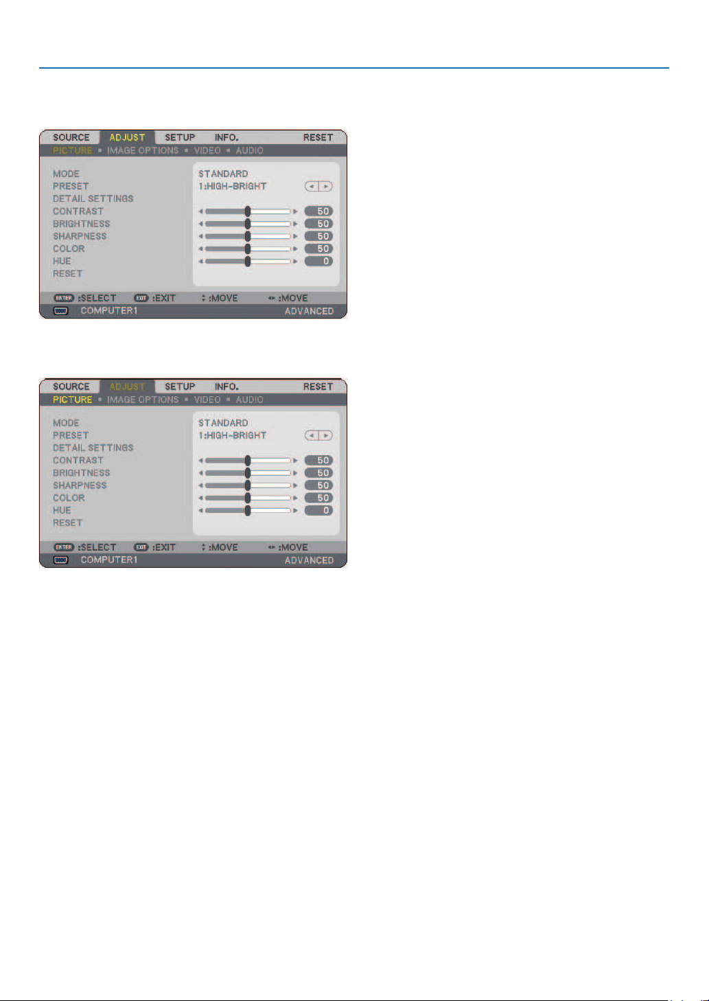
75
6. Using On-Screen Menu
❺
Menu Descriptions & Functions [ADJUST]
[PICTURE]
[MODE]
This function allows you to determine how to save settings for [DETAIL SETTINGS] of [PRESET] for each input.
STANDARD............ Saves settings for each item of [PRESET] (PRESET 1 through 6)
PROFESSIONAL .... Saves all the settings of [PICTURE] for each input.
[PRESET]
This option allows you to adjust neutral tint for yellow, cyan or magenta. There are six factory presets optimized for
various types of images, you can set user adjustable settings.

76
6. Using On-Screen Menu
[DETAIL SETTINGS]
This will provide you with two pages of menus that provide more detailed settings.
[GENERAL]
Selecting Reference Setting [REFERENCE]
This feature allows you to use color correction or gamma values as reference data to optimize for various
types of images. You can select one of the following six settings.
HIGH-BRIGHT ....................Recommended for use in a brightly lit room.
PRESENTATION .................Recommended for making a presentation using a PowerPoint fi le.
VIDEO .................................Recommended for typical TV program viewing.
MOVIE ................................Recommended for movies.
GRAPHIC ............................Recommended for graphics.
sRGB ..................................Standard color values.
Selecting Gamma Correction Mode [GAMMA CORRECTION]
Each mode is recommended for:
DYNAMIC ...........................Creates a high-contrast picture.
NATURAL ...........................Natural reproduction of the picture.
BLACK DETAIL ...................Emphasizes detail in dark areas of the picture.
Adjusting Color Temperature [COLOR TEMPERATURE]
This option allows you to select the color temperature of your choice.
NOTE:
• When [PRESENTATION] or [HIGH-BRIGHT] is selected in [REFERENCE], this function is not available.
• When [WHITE BALANCE] settings has been changed, the color temperature value on screen does not refl ect the real color
temperature.
[WHITE BALANCE]
Adjusting White Balance [WHITE BALANCE]
This allows you to adjust the white balance. Contrast for each color (RGB) to adjust the white level of the
screen; Brightness for each color (RGB) is used to adjust the black level of the screen.

77
6. Using On-Screen Menu
[CONTRAST]
Adjusts the intensity of the image according to the incoming signal.
[BRIGHTNESS]
Adjusts the brightness level or the back raster intensity.
[SHARPNESS]
Controls the detail of the image for Video. (not valid for RGB and digital signals).
[COLOR]
Increases or decreases the color saturation level (not valid for RGB and digital signals).
[HUE]
Varies the color level from +/- green to +/-blue. The red level is used as reference. This adjustment is only valid for
Video, Component and TV standard inputs (not valid for RGB and digital signals).
Input signal
CONTRAST BRIGHTNESS SHARPNESS COLOR HUE
Computer/HDMI (RGB) Yes Yes No No No
Computer/HDMI (Component) Yes Yes Yes Yes Yes
Video, S-Video Yes Yes Yes Yes Yes
Viewer, Network Yes Yes No No No
Yes=Adjustable, No=Not adjustable
[RESET]
The settings and adjustments for [PICTURE] will be returned to the factory settings with the exception of the follow-
ing; Preset numbers and [REFERENCE] within the [DETAIL SETTINGS] screen when [STANDARD] is selected in
[MODE].
The settings and adjustments under [DETAIL SETTINGS] within the [PRESET] screen that are not currently se-
lected will not be reset.
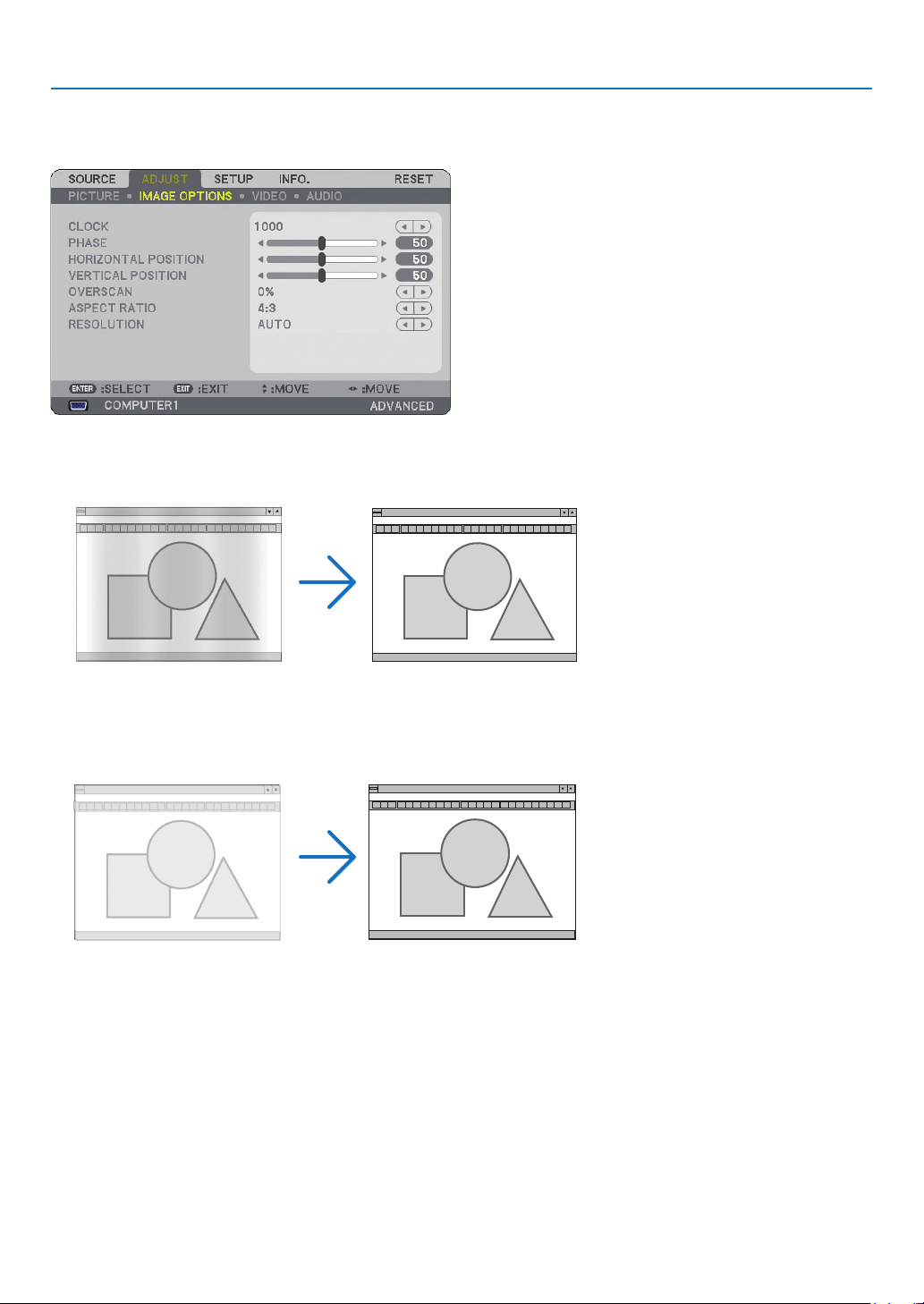
78
6. Using On-Screen Menu
[IMAGE OPTIONS]
Adjusting Clock and Phase [CLOCK/PHASE]
This allows you to manually adjust Clock and Phase.
CLOCK ................... Use this item to fi ne tune the computer image or to remove any vertical banding that might appear.
This function adjusts the clock frequencies that eliminate the horizontal banding in the image.
This adjustment may be necessary when you connect your computer for the fi rst time.
PHASE ................... Use this item to adjust the clock phase or to reduce video noise, dot interference or cross talk. (This is
evident when part of your image appears to be shimmering.)
Use [PHASE] only after the [CLOCK] is complete.
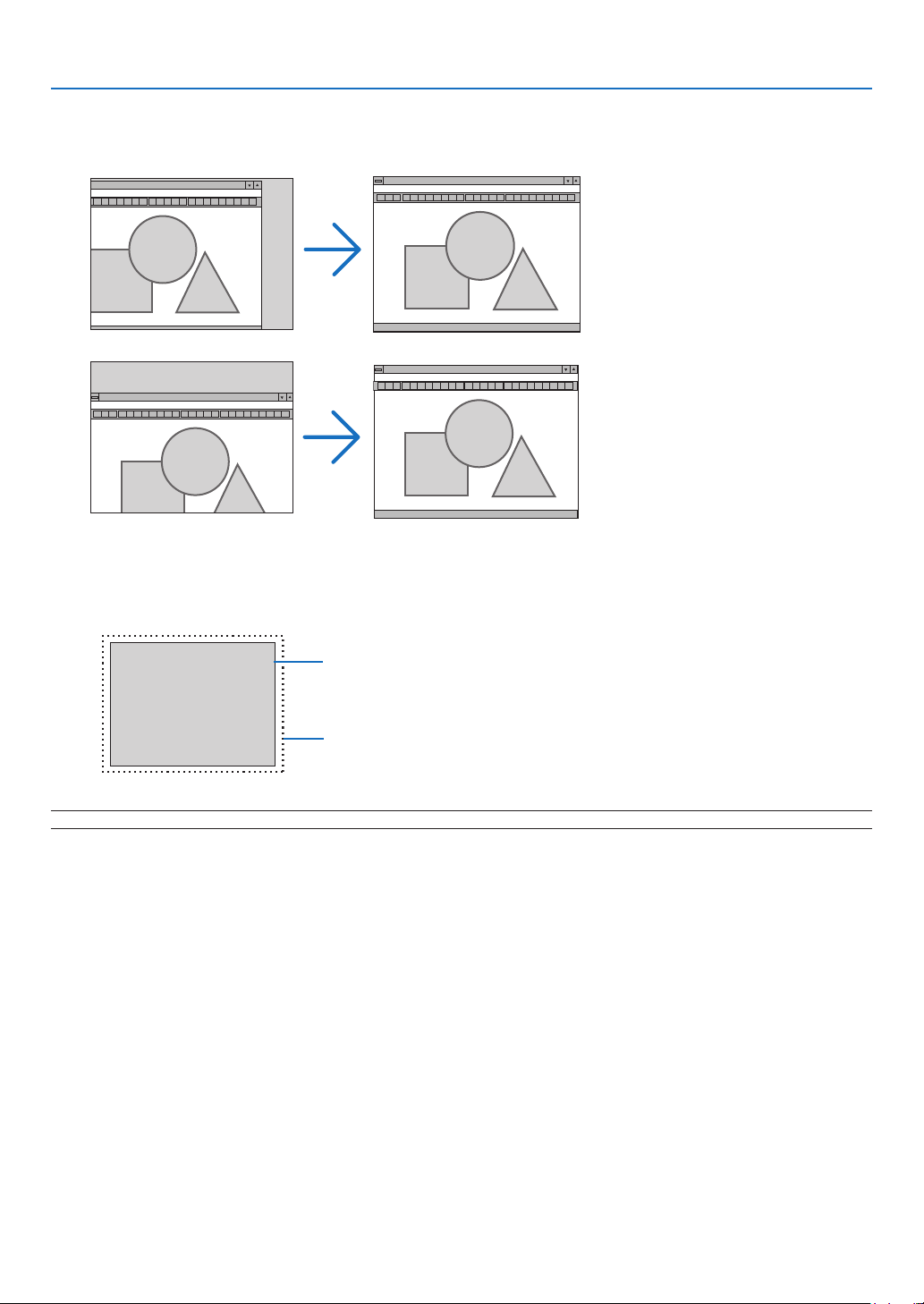
79
6. Using On-Screen Menu
Adjusting Horizontal/Vertical Position [HORIZONTAL/VERTICAL POSITION]
Adjusts the image location horizontally and vertically.
Selecting Overscan Percentage [OVERSCAN]
Select overscan percentage (0%, 5% and 10%) for signal.
Projected image
Overscaned by 10%
NOTE: When [NATIVE] is selected in [RESOLUTION], [OVERSCAN] is not available.
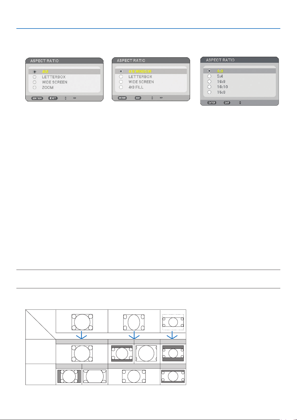
80
6. Using On-Screen Menu
Selecting Aspect Ratio [ASPECT RATIO]
Screen Type 4:3 SCREEN (VIDEO) Screen Type WIDE SCREEN (VIDEO) RGB
Aspect Ratio allows you to select the best Aspect mode to display your source image.
When screen type 4:3 SCREEN is selected for the source, the following selections will display:
For VIDEO
4:3 ......................... Standard 4:3 aspect
LETTERBOX .......... Reduced to display the true aspect with black borders on top and bottom
WIDE SCREEN ....... Left & Right stretched with black borders on top and bottom
ZOOM .................... Left & Right stretched. Left & Right sides cut. Available for 4:3 only.
When screen type WIDE SCREEN is selected for the source, the following selections will display:
For VIDEO
4:3 WINDOW ......... Reduced to display the true aspect with black borders on right and left
LETTERBOX .......... Standard 16:9 aspect
WIDE SCREEN ....... Left and right stretched to display the true aspect
4:3 FILL ................. Stretched to display in 16:9 aspect ratio
For RGB
4:3 ......................... For a video signal with an aspect ratio of 4:3
5:4 ......................... For a video signal with an aspect ratio of 5:4
16:9 ....................... For a video signal with an aspect ratio of 16:9
16:10 ..................... For a video signal with an aspect ratio of 16:10
15: 9 ...................... For a video signal with an aspect ratio of 15:9
NOTE:
• You can adjust image position vertically for a source with black borders on top and bottom. (→ page
94)
• When [NATIVE] is selected in [RESOLUTION], [ASPECT RATIO] is not available.
VIDEO
Input
Signal
Screen
Type
4:3
SCREEN
WIDE
SCREEN
4:3
SQUEEZE
LETTERBOX
4:3
WIDE SCREEN
ZOOM
LETTERBOX
LETTERBOX
WIDE SCREEN
4:3 WINDOW 4:3 Fill
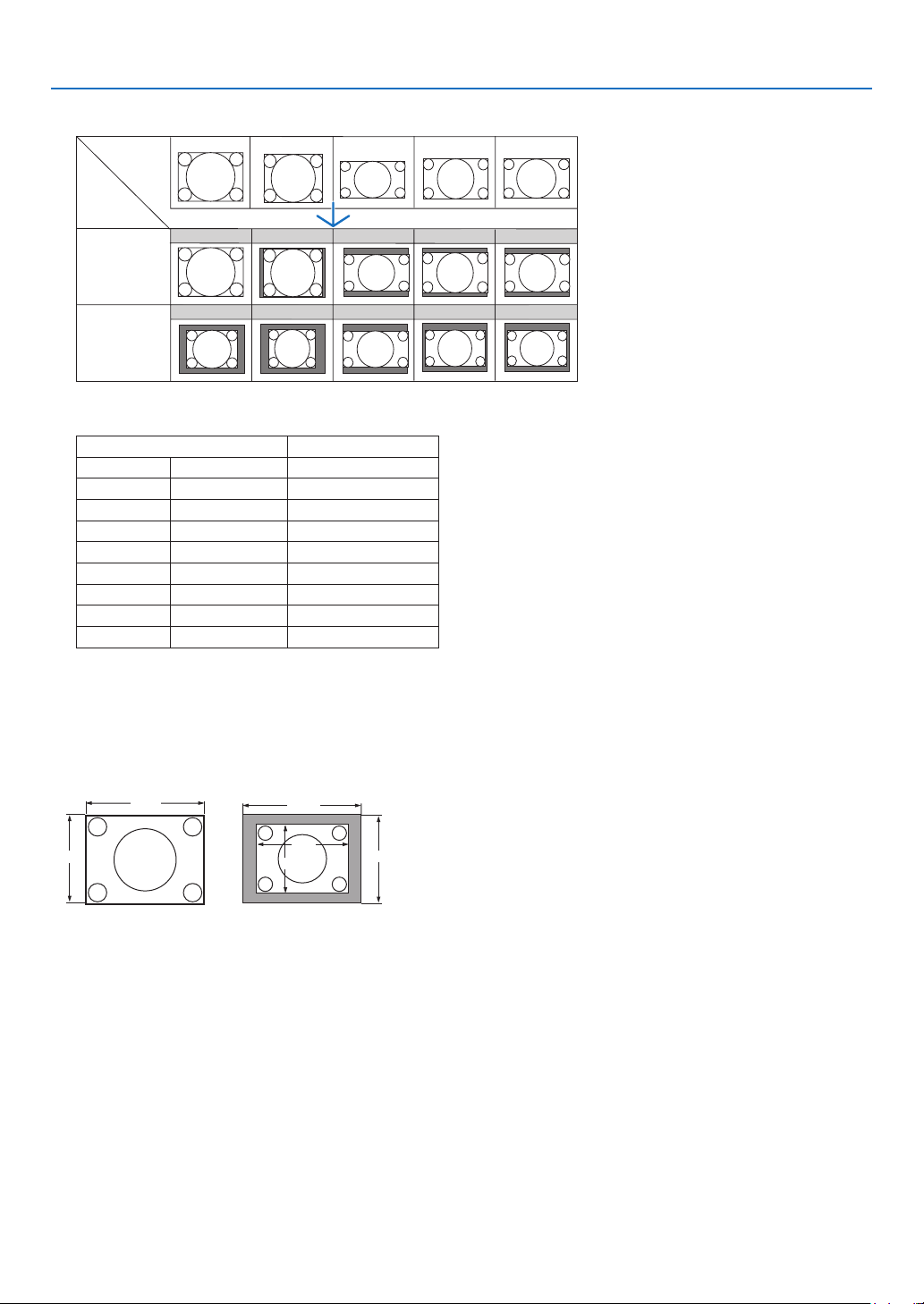
81
6. Using On-Screen Menu
RGB (HDMI included)
Typical resolutions and aspect ratios for computer screens.
Resolution Aspect Ratio
VGA 640 x 480 4:3
SVGA 800 x 600 4:3
XGA 1024 x 768 4:3
WXGA 1280 x 768 15:9
WXGA 1280 x 800 16:10
WXGA+ 1440 x 900 16:10
SXGA 1280 x 1024 5:4
SXGA+ 1400 x 1050 4:3
UXGA 1600 x 1200 4:3
Selecting Resolution [RESOLUTION]
[AUTO] : Displays an RGB signal to t the screen in the projector’s native resolution (1024 x 768 pixels).
[NATIVE] : Displays an RGB signal in its true resolution.
Example: When a source with 800 x 600 pixels is selected using the VT800:
1024
768
1024
768
600
800
• When [NATIVE] is selected, [OVERSCAN] and [ASPECT] is not available.
• [RESOLUTION] is not available under the following conditions:
- When [SCREEN TYPE] is set for the resolution other than the projector’s native resolution.
- When a signal other than RGB is selected.
- When a signal with a higher resolution than the projector’s native resolution is displayed.
Input
Signal
Screen
Type
4:3
SCREEN
WIDE
SCREEN
4:3
4:3 5:4 16:10
4:3 5:4
5:4 16:9 16:10
16:9
16:1016:9
15:9
15:9
15:9
[NATIVE][AUTO]
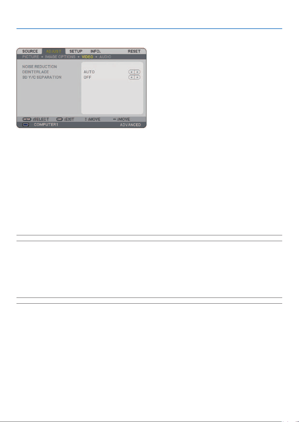
82
6. Using On-Screen Menu
[VIDEO]
Using Noise Reduction [NOISE REDUCTION]
This function is used to reduce video noise.
RANDOM NR ......... Reduces fl ickering random noise in an image.
MOSQUITO NR ...... Reduces mosquito noise that appears around the edges of an image during DVD playback.
BLOCK NR ............. Reduces block noise or mosaic-like patterns by selecting ON.
Selecting Interlaced Progressive Conversion Process Mode [DEINTERLACE]
This function allows you to select an interlaced-to-progressive conversion process for video signals.
AUTO ..................... Determines an appropriate interlaced-to-progressive conversion process automatically.
VIDEO .................... Applies a normal interlaced-to-progressive conversion process.
FILM ...................... Applies the automatic detection mode for telecine signals. This option is recommended for a movie
picture.
NOTE: This function is not available with RGB signals.
Turning On or Off the 3D Dimensional Separation [3D Y/C SEPARATION]
When projecting an image from a VIDEO input, set to ON to project the highest quality image.
OFF ........................ Turns off the 3 dimensional separation feature.
ON ......................... Turns on the 3 dimensional separation feature.
NOTE: Only available for NTSC 3.58 video signals.
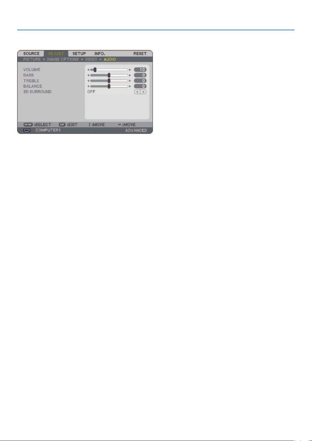
83
6. Using On-Screen Menu
[AUDIO]
Controlling Sound [VOLUME/BASS/TREBLE/BALANCE]
Adjusts the volume, bass and treble level, left and right balance of the projector speaker and AUDIO OUT (Stereo
Mini Jack).
Enabling 3D Surround [3D SURROUND]
Turn on or off the 3D surround effect.
If the AUDIO OUT stereo mini jack of the projector is connected to external equipment, adjusting the sound on the
external equipment can cause sound to be distorted or cracked, depending on the bass, treble or 3D Surround
adjustment. If this happens, return the adjustments of the projector to the factory default (BASS: 0, TREBLE: 0, 3D
SURROUND: OFF).
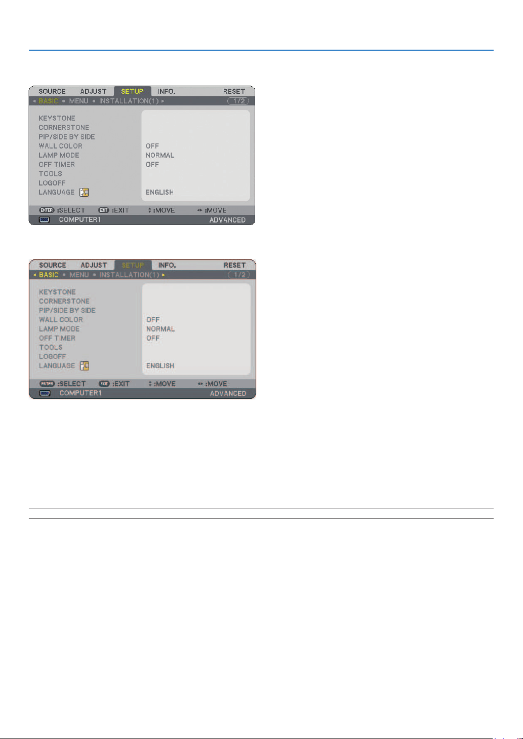
84
6. Using On-Screen Menu
❻
Menu Descriptions & Functions [SETUP]
[BASIC]
Selecting Keystone Mode [KEYSTONE]
This feature allows you to correct keystone distortion.
Selecting this item will display the Keystone setting menu.
[AUTO KEYSTONE] will turn on the auto keystone feature.
Changes will be saved even when you turn off the projector.
You can correct vertical distortion manually from the menu. (→ page
26)
To do do, select [OFF] on the [AUTO KEYSTONE] screen.
NOTE: When [CORNERSTONE] is selected, [KEYSTONE] is not available.

85
6. Using On-Screen Menu
Selecting Cornerstone Mode [CORNERSTONE]
This option allows you to correct trapezoidal distortion.
Selecting this item will display the Cornerstone adjustment screen. (→ page 36)
NOTE: When [KEYSTONE] is selected, [CORNERSTONE] is not available.
Using the PIP/SIDE BY SIDE Function
This function allows you to view two different signals simultaneously. (→ page
39)
MODE:
This option allows you to select two modes: PIP and Side by Side.
PIP: This option allows you to view a sub picture in the main picture.
SIDE BY SIDE: This allows you to view two pictures side by side.
POSITION:
When [PIP] is selected for [MODE], this option allows you to select the position of a sub picture in the main
picture.
The options are: top-left, top-right, bottom left, and bottom right.
NOTE: The [POSITION] cannot be selected when [SIDE BY SIDE] is selected.
SOURCE:
This option allows you to select a sub picture signal.
The options are: OFF, VIDEO and S-VIDEO.
Selecting [OFF] will cancel the PIP/SIDE BY SIDE mode and return to the normal screen.
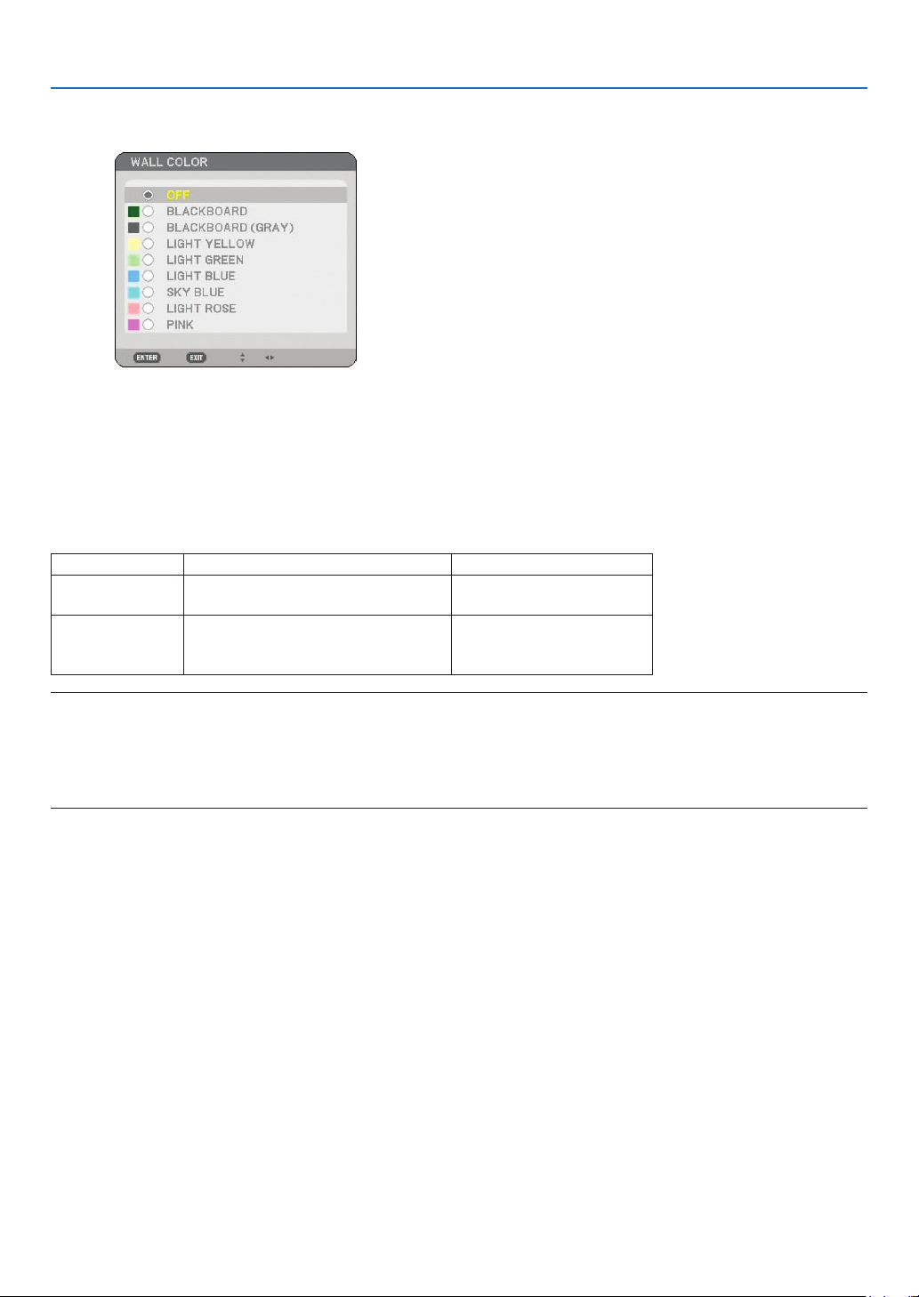
86
6. Using On-Screen Menu
Using the Wall Color Correction [WALL COLOR]
This function allows for quick adaptive color correction in applications where the screen material is not white.
The following nine options are available.
Setting Lamp Mode to Normal or Eco [LAMP MODE]
This feature enables you to select two brightness modes of the lamp: NORMAL and ECO modes. The lamp life
can be extended by using the ECO mode. Selecting ECO mode decreases fan noise when compared to NORMAL
mode.
Lamp Mode Description Status of LAMP indicator
NORMAL
This is the Default setting
(100% Brightness).
Off
ECO
Select this mode to increase the
lamp life (approx. 80% Brightness
light output)
Steady Green light
NOTE: If the projector is overheated in NORMAL mode, there may be a case where the LAMP MODE will be forced into the ECO
mode to protect the projector. This mode is called “forced ECO mode”.
When the projector is in forced ECO mode, the picture brightness decreases. The LAMP indicator’s steady green light indicates
the lamp is in ECO mode.
When the projector comes back to normal temperature, the LAMP MODE returns to NORMAL mode.
In the forced ECO mode, changing [LAMP MODE] setting in the menu will not affect the actual LAMP MODE.
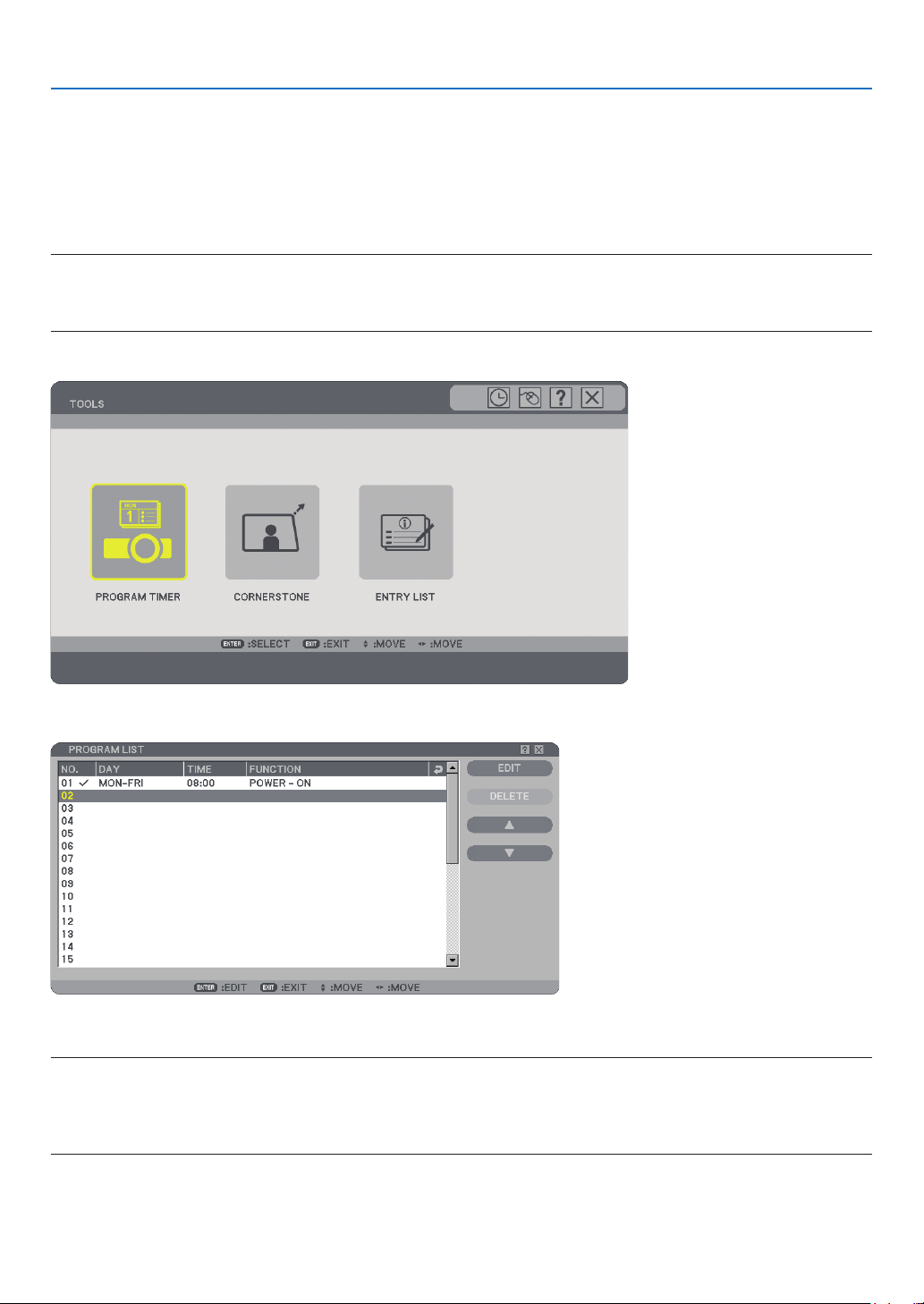
87
6. Using On-Screen Menu
Using Off Timer [OFF TIMER]
1. Select your desired time between 30 minutes and 16 hours: OFF, 0:30, 1:00, 2:00, 4:00, 8:00, 12:00,
16:00.
2. Press the ENTER button on the remote control.
3. The remaining time starts counting down.
4. The projector will turn off after the countdown is complete.
NOTE:
• To cancel the preset time, set [OFF] for the preset time or turn off the power.
• When the remaining time reaches 3 minutes before the projector is turned off, the [THE PROJECTOR WILL TURN OFF WITHIN
3 MINUTES] message will be displayed on the bottom of the screen.
[TOOLS]
Using Program Timer [PROGRAM TIMER]
This option turns on/off the projector and changes video signals automatically at a speci ed time.
NOTE:
• Before setting the Program Timer, make sure that the [DATE, TIME PRESET] feature is set. (→ page
90)
• Make sure that the projector is in the stand by condition with the Main Power Switch on.
• The projector has a built-in clock. The clock will keep working for about two weeks after the main power is turned off. If the
main power is not supplied to the projector for two weeks or more, the built-in clock stops working.
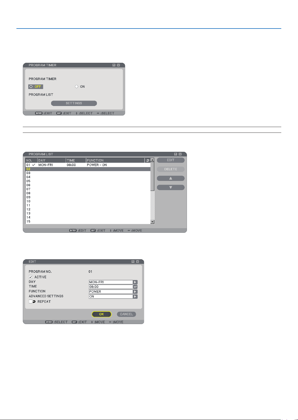
88
6. Using On-Screen Menu
Setting a new program timer
1. On the PROGRAM TIMER screen, use the SELECT ▲ or
왔
button to select [SETTINGS] and press the EN-
TER button.
The [PROGRAM LIST] screen will be displayed.
NOTE: When the Program Timer is turned on, the [PROGRAM LIST] cannot be edited.
2. Select a blank program number and press the ENTER button.
The [EDIT] screen will be displayed.
3. Make settings for each item as required.
ACTIVE .................. Place a check mark to enable the program.
DAY ....................... Select days of the week for the program timer. To execute the program from Monday to Friday, select
[MON-FRI].To execute the program in everyday basis, select [EVERYDAY].
TIME ...................... Set the time to execute the program. Enter time in 24-hour format.
FUNCTION ............. Select a function to be executed. Selecting [POWER] will allow you to turn on or off the projector by
setting [ADVANCED SETTINGS]. Selecting [SOURCE] will allow you to select a video source by setting
[ADVANCED SETTINGS].
ADVANCED SETTINGS
. Select power on/off or a type of video source for the selected item in [FUNCTION].
REPEAT ................. Place a check mark to repeat the program continuing basis . To use the program this week only, clear
the check mark.

89
6. Using On-Screen Menu
4. Select [OK] and press the ENTER button.
This will complete the settings.
You will be returned to the [PROGRAM LIST] screen.
NOTE:
• Up to 30 different timer settings can be programmed.
• When [PROGRAM TIMER] is turned on, the [STANDBY MODE] setting is ignored.
• The Program Timer is executed on a set time basis, not in a program basis.
• Once the program not marked with a check in [REPEAT] has been executed, the check mark in the [ACTIVE] check box will be
cleared automatically and the program will be disabled.
• When the on-time and the off-time set for the same time, the off-time setting will take preference.
• Two different sources are set for the same time, the larger program number will take preference.
• The on-time setting will not be executed while the cooling fans are running or an error is occurring.
• If the off-time setting is expired under the condition in which the power off is not possible, the off-timer setting will not be ex-
ecuted until the power off becomes possible.
• Programs not marked with a check mark in [ACTIVE] of the [EDIT] screen will not be executed even if the Program Timer is en-
abled.
• When the projector is turned on by using the program timer and if you want to turn off the projector, set the off-time or do it
manually so as not to leave the projector on for a long period of time.
Activating the program timer
1. Select [ON] on the [PROGRAM TIMER] screen and press the ENTER button.
The [ON] will be activated.
2. Press the EXIT button.
The [PROGRAM TIMER] screen will be changed to the [TOOL] screen.
NOTE:
• Selecting [OFF] will disable the Program Timer even when a program is marked with a check mark on [PROGRAM LIST]
screen.
• When the [ON] is turned on, the [PROGRAM LIST] cannot be edited. To edit the programs, select [OFF] to turn off the Program
Timer.
Changing the programmed settings
1. On the [PROGRAM LIST] screen, select a program you want to edit and press the ENTER button.
2. Change the settings on the [EDIT] screen.
3. Select [OK] and press the ENTER button.
The programmed settings will be changed.
You will be returned to the [PROGRAM LIST] screen.
Changing the order of programs
1. On the [PROGRAM LIST] screen, select a program whose order you want to change and press the SE-
LECT ▶ button.
2. Press the SELECT ▼ button to select
왖
or ▼.
3. Press the ENTER button a few times to select a row to which you wish to move the program.
The order of the programs will be changed.

90
6. Using On-Screen Menu
Deleting the programs
1. On the [PROGRAM LIST] screen, select a program number you want to delete and press the SELECT ▶
button.
2. Press the SELECT ▼ button to select [DELETE].
3. Press the ENTER button.
The confirmation screen will be displayed.
4. Select [YES] and press the ENTER button.
The program will be deleted.
This will complete deleting the program.
Using [CORNERSTONE]
(→ page
36)
Using [ENTRY LIST]
(→ page 73)
Setting the Current Date and Time [DATE, TIME PRESET]
You can set the current time, month, date, and year.
NOTE: The projector has a built-in clock. The clock will keep working for about 2 weeks after the main power is turned off. If the
main power is off for 2 weeks or more, the built-in clock will cease. If the built-in clock ceases, set the date and time again. The
built-in clock will not cease while in the standby mode.
TIME ZONE: Select your time zone.
DAYLIGHT SAVING TIME: Place a check mark to adjust the clock for daylight saving changes.
INTERNET TIME SERVER: Place a check mark to turn on clock synchronization. When this option is turned on,
the projector’s built-in clock will be synchronized with an Internet timer server in every 24 hours and at the time of
projector’s start up.
UPDATE button: Synchronizes the projector’s built-in clock immediately.
The UPDATE button is not available unless the INTERNET TIME SERVER check box is turned on.
Setting Mouse Pointer, Button and Sensitivity [MOUSE]
This option lets you to change your USB mouse settings. The mouse settings feature is available for USB mouse
only. Choose the settings you want:
MOUSE BUTTON ................[RIGHT HAND] or [LEFT HAND]
MOUSE SENSITIVITY ........[FAST], [MEDIUM] or [SLOW]
Using [HELP]
(→ page 32)
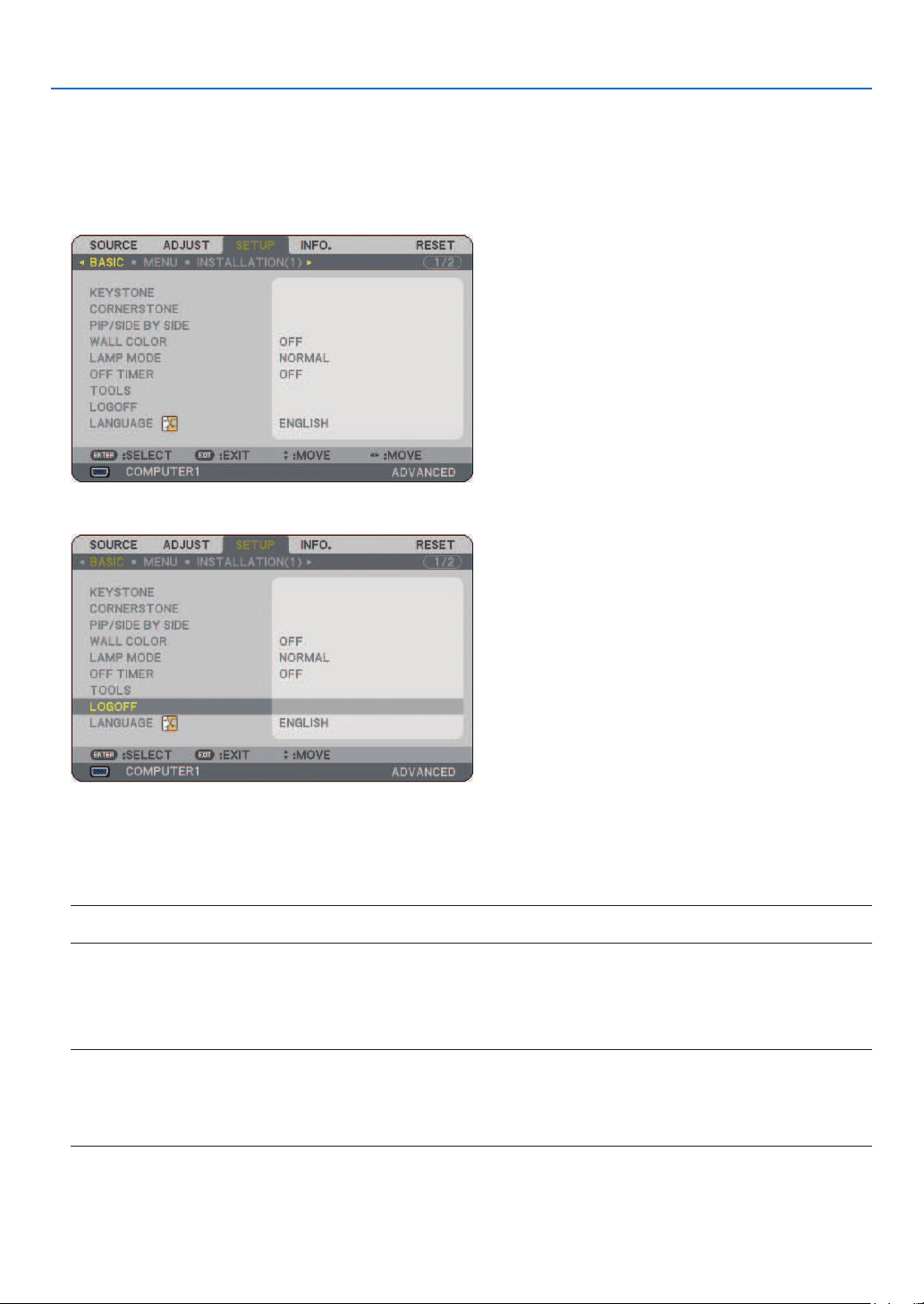
91
6. Using On-Screen Menu
Logging Off Your Projector [LOGOFF]
This feature allows you to log off your projector without turning it off.
Logging off your projector will prevent an unauthorized user from operating your projector.
To log off your projector, follow the steps below.
1. Press the MENU button and use the SELECT ▶ button to highlight [SETUP].
2. Use the SELECT ▼ or the ENTER button to highlight [BASIC].
3. Use the SELECT ▼ button to highlight [LOGOFF], and press the ENTER button.
The [LOG OFF PROJECTOR. /ARE YOU SURE?] message will be displayed.
4. Select [YES] and press the ENTER button to log off your projector and close the menu, and then the
LOGON screen will be displayed.
NOTE:
• When selecting [NO] and press the ENTER button, you will return to the Logoff screen in Step 2.
To log on your projector, select a user name, then enter your password and select [OK] and press the ENTER
button.
The LOGON screen will close. Logging on your projector is done.
NOTE:
The default LOGON screen will be shown as follows:
USER NAME → ADMINISTRATOR
PASSWORD → No setting
See “Limiting Access Level to Available Menu Items” on page
47 for entering a user name and assigning a password.
Selecting Menu Language [LANGUAGE]
You can choose one of 21 languages for on-screen instructions.
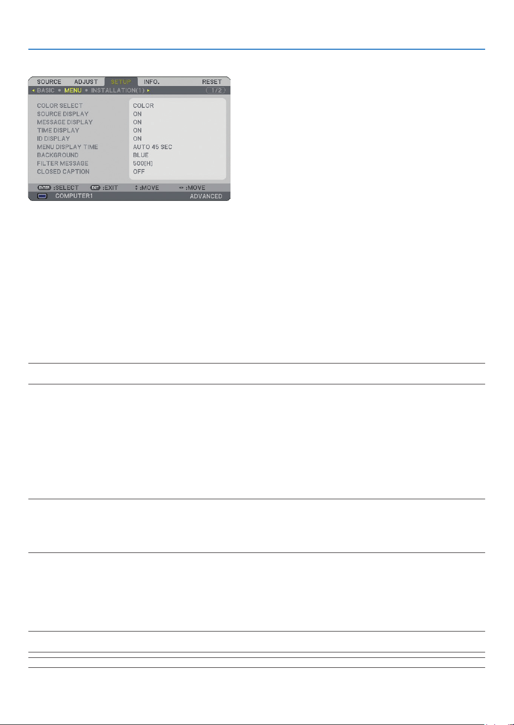
92
6. Using On-Screen Menu
[MENU]
Selecting Menu Color [COLOR SELECT]
You can choose between two options for menu color: COLOR and MONOCHROME.
Turning On / Off Source Display, Message and Time [SOURCE DISPLAY], [MESSAGE DISPLAY],
[TIME DISPLAY], [ID DISPLAY]
SOURCE DISPLAY ....... This option turns on or off input name display such as COMPUTER1, COMPUTER2, HDMI, VIDEO,
and No Input to be displayed on the top right of the screen.
MESSAGE DISPLAY .... This option turns on or off messages. Even though selecting [OFF], the following message will ap-
pear.
• “PROJECTOR IS LOCKED”. When the projector security is unlocked, the message will disappear.
TIME DISPLAY ............ This option turns on or off the current time displayed on the top left of the screen.
ID DISPLAY .................This option turns on or off the ID number which is displayed when the ID SET button on the remote
control is pressed.
NOTE: The source and current time will be displayed for the time specifi ed in [MENU DISPLAY TIME]. When [MANUAL] is se-
lected in [MENU DISPLAY TIME], the source and current time will be always displayed.
Selecting Menu Display Time [MENU DISPLAY TIME]
This option allows you to select how long the projector waits after the last touch of a button to turn off the menu.
The preset choices are [MANUAL], [AUTO 5 SEC], [AUTO 15 SEC], and [AUTO 45 SEC]. The [AUTO 45 SEC] is
the factory preset.
Selecting a Color or Logo for Background [BACKGROUND]
Use this feature to display a blue/black screen or logo when no signal is available. The default background is blue.
You can change the logo screen using the Viewer feature. (→ page
66)
NOTE:
• Your setting will not be affected even when [RESET] is done from the menu.
• When the BACKGROUND LOCK in [SECURITY SETTINGS] is turned on, the background cannot be changed.
• When the HDMI IN input is selected with no signal applied, the blue screen is displayed regardless if [LOGO] is selected in
[BACKGROUND] of the menu.
Selecting Interval Time for Filter Message [FILTER MESSAGE]
This option allows you to select the time preference between displaying the message for cleaning the lters. Clean
the lter when you get the message “PLEASE CLEAN FILTER.” (→ page
114)
Five options are available: OFF, 100[H], 200[H], 500[H], 1000[H]
The default setting is 500[H].
NOTE: The message for fi lter cleaning will be displayed for one minute when the projector is turned on or off. To cancel the
message, press any button on the projector cabinet or the remote control.
NOTE: Your setting will not be affected even when [RESET] is done from the menu.
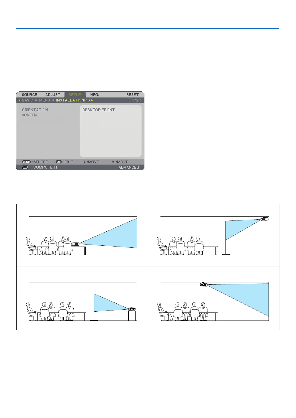
93
6. Using On-Screen Menu
Setting Closed Caption [CLOSED CAPTION]
This option sets several closed caption modes that allow text
to be superimposed on the projected image of VIDEO or S-VIDEO.
OFF ..............................This exits the closed caption mode.
CAPTION 1-4 ...............Text is superimposed.
TEXT 1-4 .....................Text is displayed in full screen.
[INSTALLATION(1)]
Selecting Projector Orientation [ORIENTATION]
This reorients your image for your type of projection. The options are: DESKTOP FRONT, CEILING REAR, DESK-
TOP REAR, and CEILING FRONT projection.
DESKTOP FRONT
CEILING REAR
DESKTOP REAR
CEILING FRONT
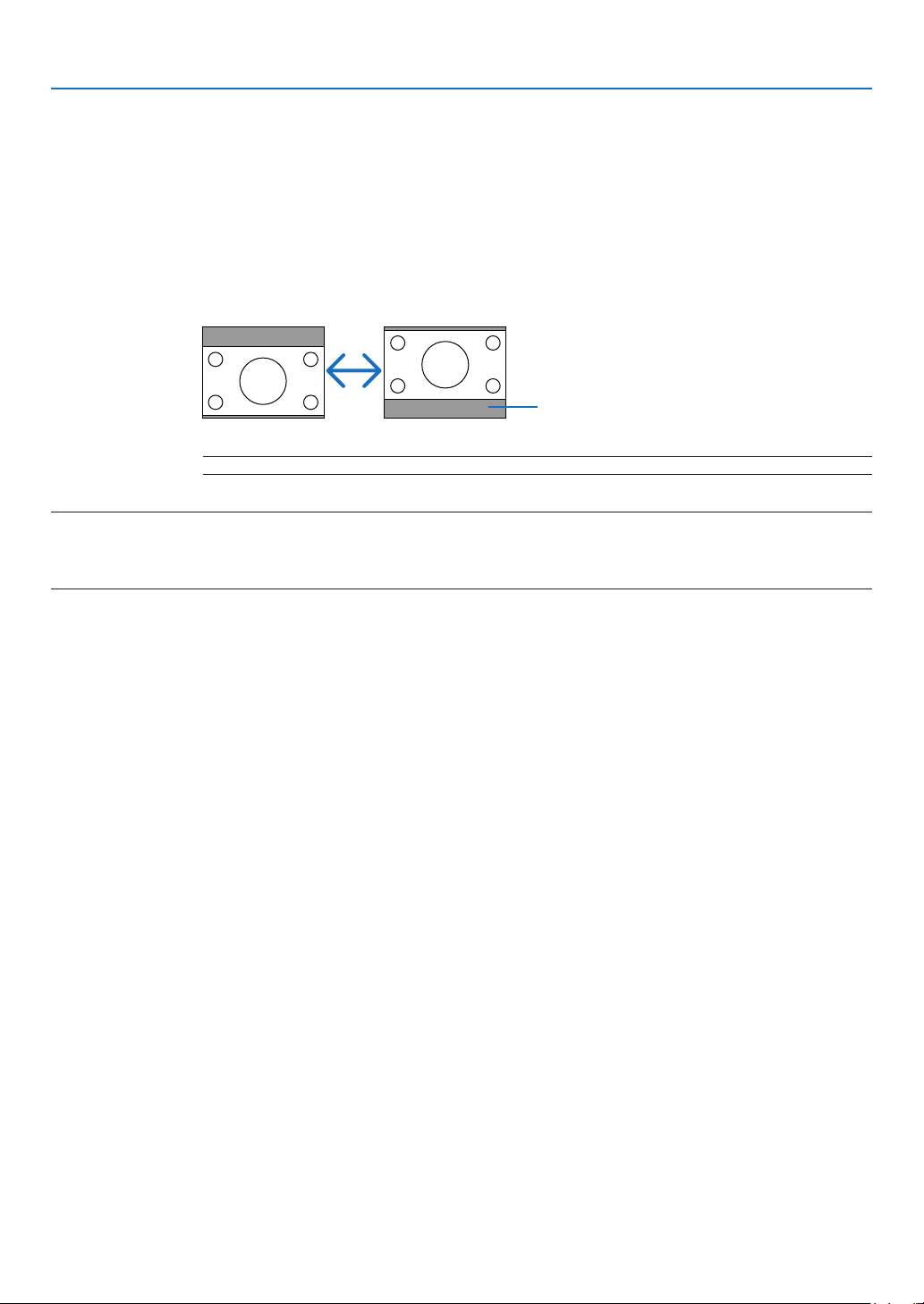
94
6. Using On-Screen Menu
Selecting Aspect Ratio and Position for Screen [SCREEN]
SCREEN TYPE ....... Select one of two options: 4:3 SCREEN or WIDE SCREEN for the screen to be used. See also [ASPECT
RATIO].
(→ page
80)
POSITION .............. This feature allows you to adjust the vertical position of the image when WIDE SCREEN has been se-
lected for the screen type.
When WIDE SCREEN has been selected there is no-signal area above and below the image.
NOTE: This option is available only when [WIDE SCREEN] is selected in [SCREEN TYPE].
NOTE:
• After changing the screen type, check the setting of [ASPECT RATIO] in the menu. (→page
80)
• [POSITION] is not available when [4:3 SCREEN] is selected for [SCREEN TYPE] or when [LETTERBOX] is selected for [Aspect
Ratio].
Blanking area or no-signal area

95
6. Using On-Screen Menu
[INSTALLATION(2)]
[NETWORK SETTINGS]
This feature allows you to set various setting items when the projector is used on your network.
CAUTION
• Consult with your network administrator about these settings.
Hints on How to Set Up LAN Connection
To con gure the projector to communicate on the network using the LAN port (RJ-45):
1. Select the [WIRED] tab for the LAN port (RJ-45).
2. On the [WIRED] tab, select a number from the [PROFILES] list for your LAN settings.
Two settings can be stored in memory for the LAN port.
3. On the [WIRED] tab, turn on or off [DHCP], specify IP address, Subnet Mask, Gateway and DNS Con-
figuration. Select [OK] and press the ENTER button.
(→ page
98)
To recall the settings from memory:
After selecting the [WIRED] tab, select the number from the [PROFILES] list.
Select [OK] and press the ENTER button. (→ page 98)
To connect a DHCP server:
On the [WIRED] tab, select [DHCP] and press the ENTER button. A check mark will be placed. Select again
and press the ENTER button. The check box will be cleared.
When setting an IP address without using a DHCP server, clear the check box for [DHCP]. (→ page 98)
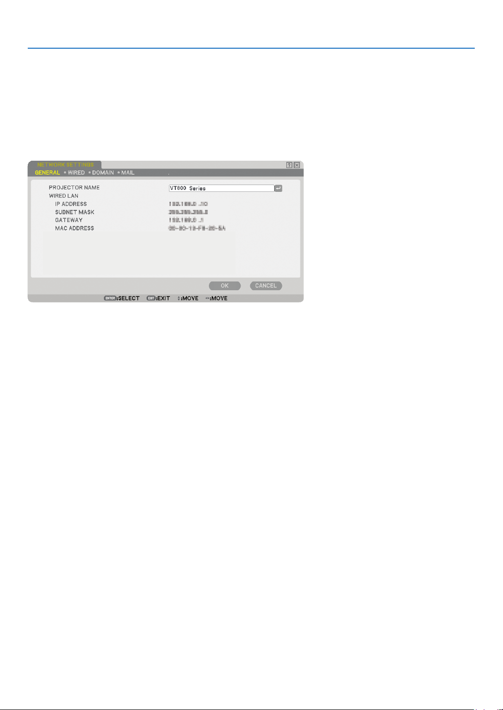
96
6. Using On-Screen Menu
To receive error messages or information on the remaining lamp life via e-mail:
1. On the [MAIL] tab, select [ALERT MAIL] and press the ENTER button. A check mark will be placed.
2. Set [SENDER’S ADDRESS], [SMTP SERVER NAME] and [RECIPIENT’S ADDRESS]. Select [OK] and
press the ENTER button.
(→ page
100)
[GENERAL]
This page allows you to specify a unique projector name and to check the current status of the LAN settings.
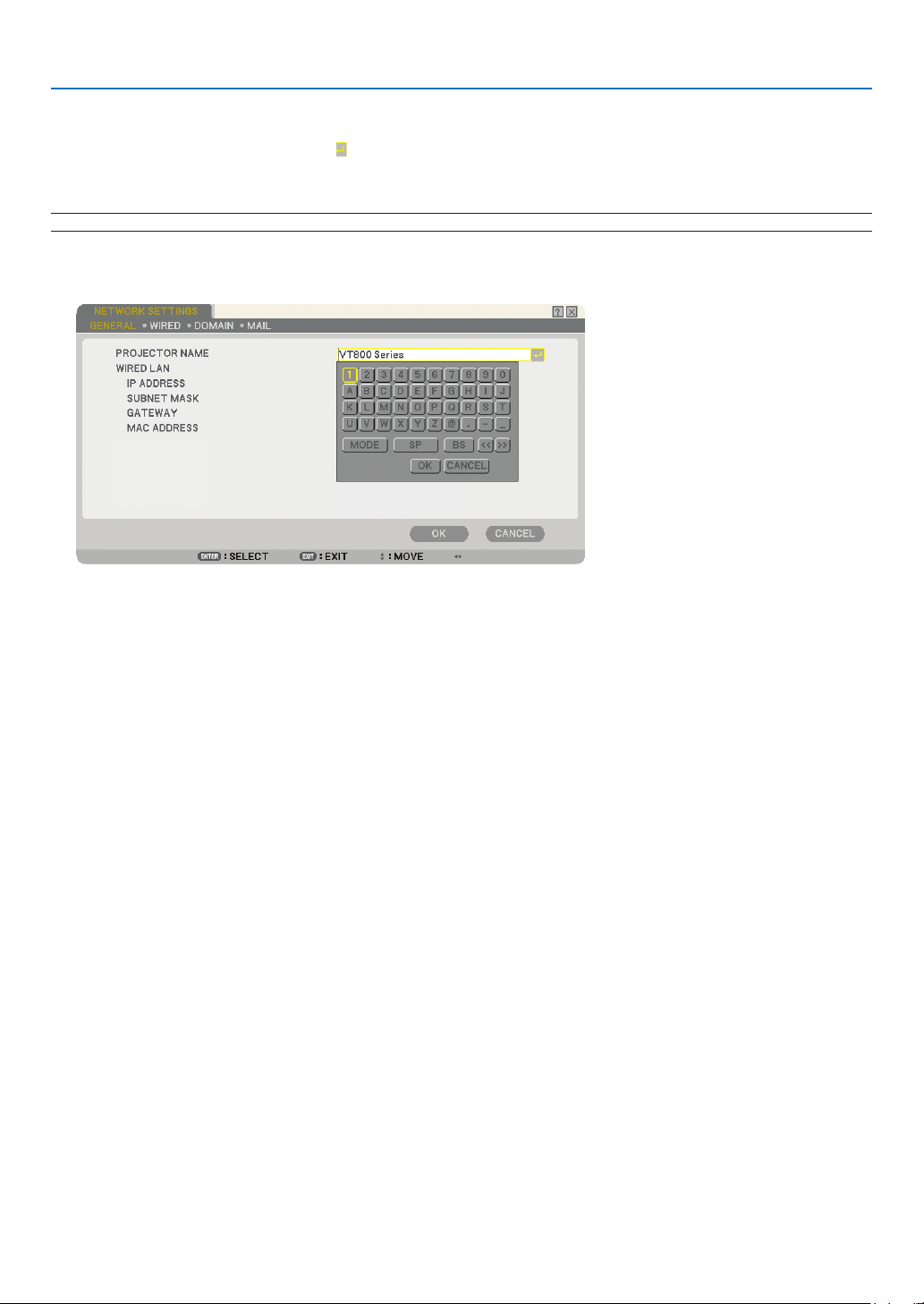
97
6. Using On-Screen Menu
[PROJECTOR NAME]
Specify a unique projector name. Press
to display the software keyboard and type in. Up to 16 alphanumeric
characters, signs and symbols can be used. After entering a name, select [OK] and press the ENTER button.
NOTE: The [PROJECTOR NAME] will not be affected even when [RESET] is done from the menu.
Using Software Keyboard
1 to 0 and
Characters ....... Use to type in password or keyword.
MODE .................... Selects one of three modes for numbers, alphabet and special characters.
SP .......................... Inserts a space
BS .......................... Deletes one character backward
<< ......................... Returns to the previous
>> ......................... Advances to the next
OK .......................... Executes the selection
CANCEL ................. Cancels the selection
(→ page
68)
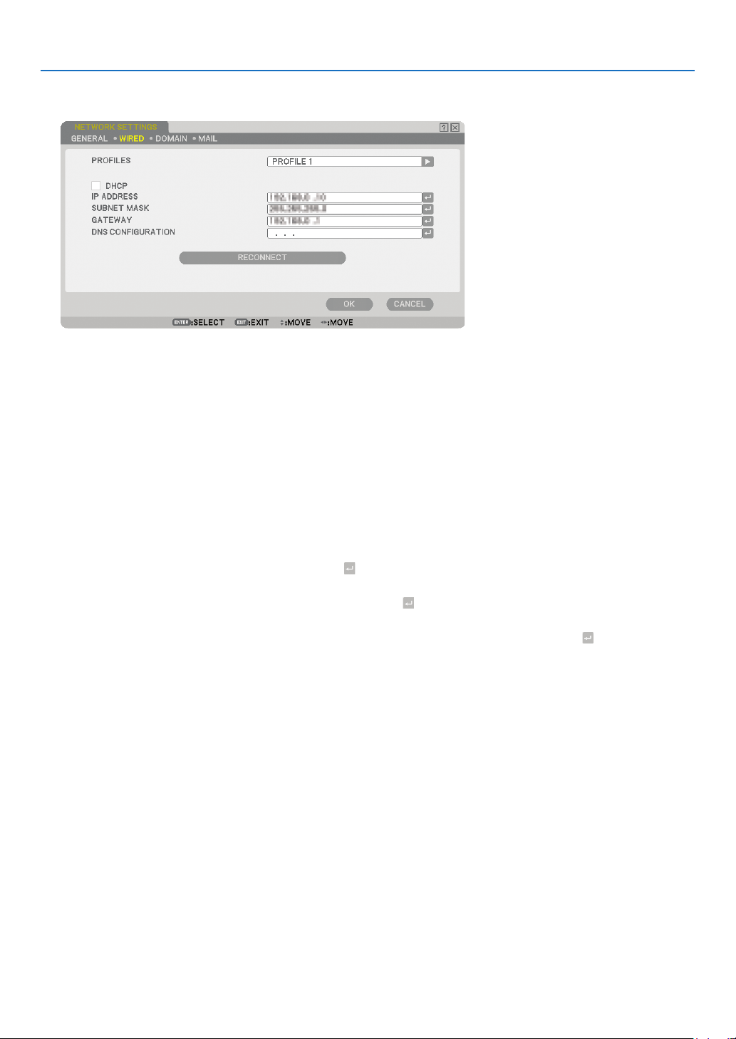
98
6. Using On-Screen Menu
[WIRED]
PROFILES (for LAN port [RJ-45]):
Up to two settings for the LAN port (RJ-45) can be stored in memory of the projector.
Select [PROFILE 1] or [PROFILE 2] and then do settings for [DHCP] and the other options.
After doing this, select [OK] and press the ENTER button. This will store your settings in memory.
To recall the settings from memory:
After selecting the [WIRED] tab, select the [PROFILE 1] or [PROFILE 2] from the [PROFILES] list.
Select [OK] and press the ENTER button.
DHCP:
Enabling this option automatically assigns an IP address to the projector from your DHCP server.
Disabling this option allows you to register the IP address or subnet mask number obtained from your network
administrator.
IP ADDRESS .......................Set your IP address. Press to display the software keyboard and type in 12 numeric charac-
ters.
SUBNET MASK...................Set your subnet mask number. Press
to display the software keyboard and type in 12 nu-
meric characters.
GATEWAY ...........................Set the default gateway of the network connected to the projector. Press
to display the soft-
ware keyboard and type in 12 numeric characters.
DNS CONFIGURATION .......Type in the IP address of DNS server on the network connected to the projector. 12 numeric
characters are used.
RECONNECT .......................Use this button to retry to connect the projector to a network. Try this if you have changed
[PROFILES].
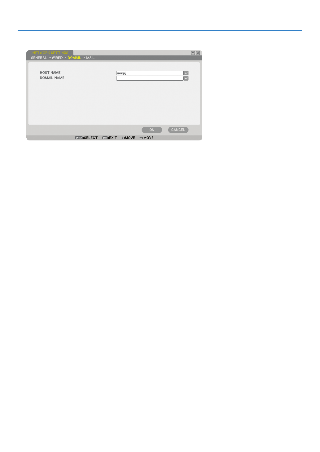
99
6. Using On-Screen Menu
[DOMAIN]
HOST NAME .......... Type in a hostname. Up to 15 alphanumeric characters can be used.
DOMAIN NAME ..... Type in domain name of the network connected to the projector. Up to 60 alphanumeric characters can
be used.
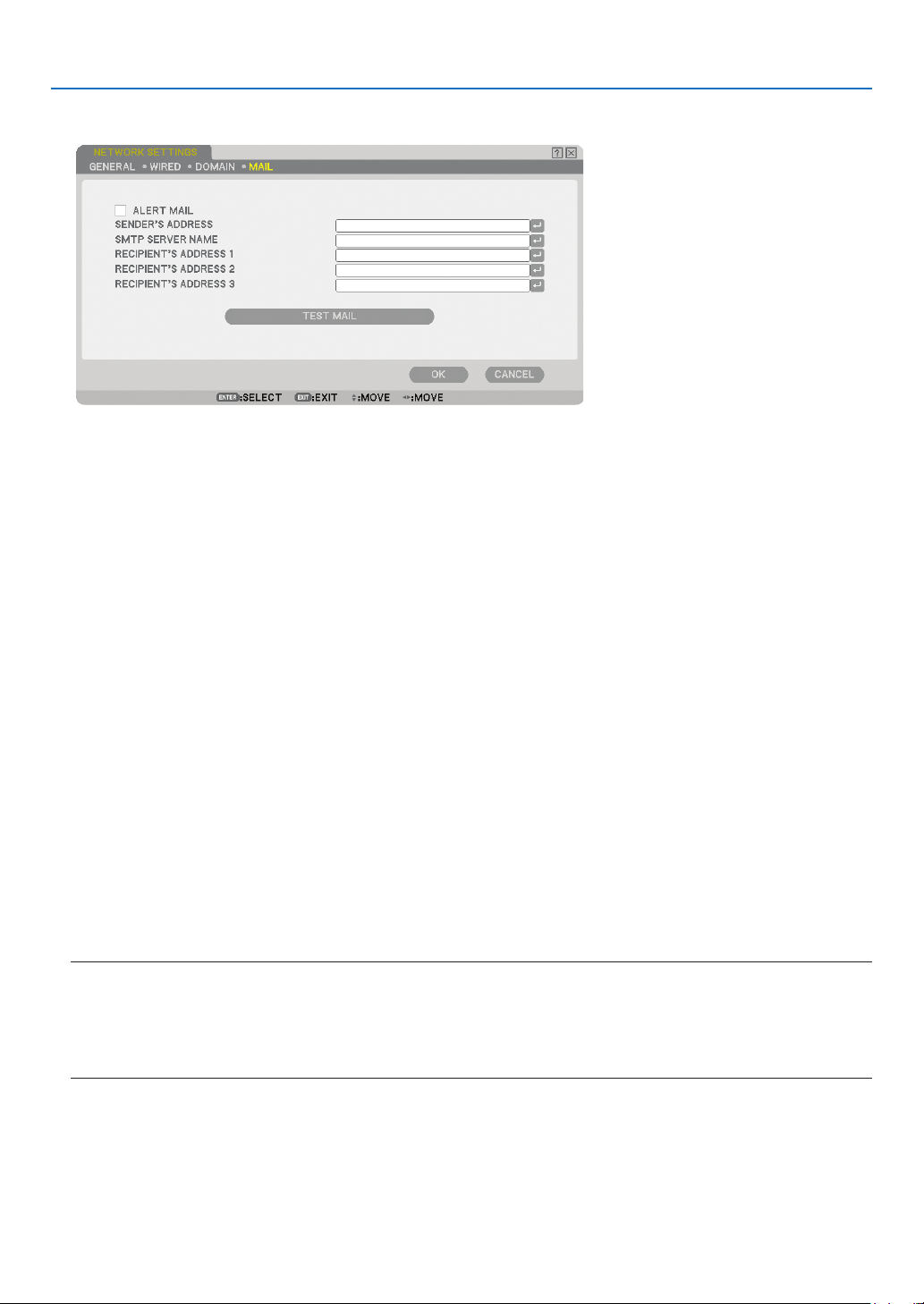
100
6. Using On-Screen Menu
[MAIL]
ALERT MAIL:
Checking this box enables Alert Mail feature.
This option noti es your computer of an error message via e-mail when using wired LAN. The error message
will be noti ed when the projector lamp has reached the end of its usable life or an error occurs in the projec-
tor.
Sample of a message sent from the projector:
The lamp is at the end of its usable life. Please replace the lamp.
Projector Name: X X X X
Lamp Hours Used: xxxx [H]
SENDER’S ADDRESS:
Specify the senders address. Use the Software keyboard. Up to 60 alphanumeric and symbols characters can
be used. See “Using Software Keyboard” in Appendix for more details.
SMTP SERVER NAME:
Type in the SMTP server name to be connected to the projector. Up to 60 alphanumeric characters can be
used.
RECIPIENT’S ADDRESS 1 to 3:
Type in your recipient’s address. Up to 60 alphanumeric and symbols characters can be used.
TEST MAIL:
Send a test mail to check if your settings are correct.
NOTE:
• If you entered an incorrect address in a test, you may not receive an Alert mail. Should this happen, check if the Recipi-
ent’s Address is correctly set.
• Unless any one of the [SENDER’S ADDRESS], [SMTP SERVER’S NAME] or [RECIPIENT’S ADDRESS 1-3] is selected, [TEST
MAIL] is not available.
• Be sure to highlight [OK] and press the ENTER button before executing [TEST MAIL].
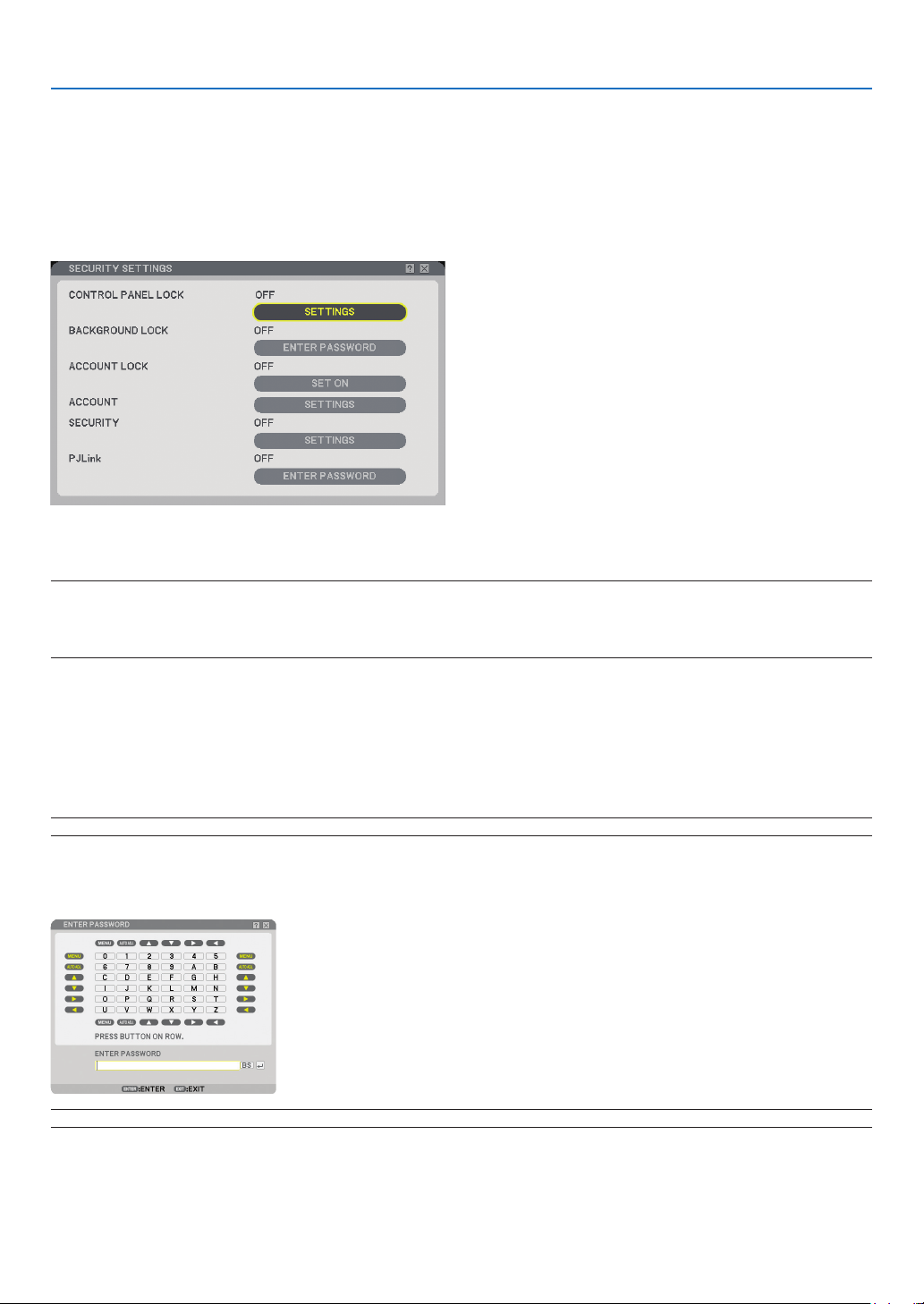
101
6. Using On-Screen Menu
Selecting Communication Speed [COMMUNICATION SPEED]
This feature sets the baud rate of the PC Control port (D-Sub 9 Pin). It supports data rates from 4800 to 38400
bps. The default is 38400 bps. Select the appropriate baud rate for your equipment to be connected (depending
on the equipment, a lower baud rate may be recommended for long cable runs).
Your selected communication speed will not be affected even when [RESET] is done from the menu.
Setting Security [SECURITY SETTINGS]
Disabling the Cabinet Buttons [CONTROL PANEL LOCK]
This option turns on or off the Control Panel Lock function.
NOTE:
• This Control Panel Lock does not affect the remote control functions.
• When the control panel is locked, pressing and holding the EXIT button on the projector cabinet for about 10 seconds will
change the setting to [OFF].
Setting a Password [BACKGROUND LOCK]
A password can be set for your projector to avoid operation by an unauthorized person.
When [BACKGROUND LOCK] is set, changing the background data in the USB memory will display the Password
input screen.
NOTE: When [BACKGROUND LOCK] is turned on, [BACKGROUND] cannot be selected from the menu.
[ENTRY]
To assign your password:
NOTE: Up to 10 alphanumeric characters can be assigned.
1. Type a password.
Select the [ENTER PASSWORD] entry box and press the ENTER button. (→ page
68)
An asterisk will be displayed.

102
6. Using On-Screen Menu
The Software keyboard appears. Use the Software keyboard to type a password on the [ENTER PASS-
WORD] screen and press the ENTER button.
The [CONFIRM PASSWORD] screen will be displayed.
2. Type the same password again and press the ENTER button.
Your password will be assigned.
[DELETE]
To delete your password:
1. Select [DELETE PASSWORD] and press the ENTER button.
2. Enter your password.
An asterisk will be displayed.
3. Press the ENTER button.
Your password will be deleted.
NOTE:
• Do not forget your password. However, if you forget your password, consult with your dealer.
• The [BACKGROUND LOCK] will not be affected even when [RESET] is done from the menu.
ACCOUNT LOCK
When [ACCOUNT LOCK] is set to [ON], you can set it to [OFF].
When [ACCOUNT LOCK] is set to [OFF], you can set it to [ON].
The [ACCOUNT] setting is available only when [ACCOUNT LOCK] is set to [OFF].
NOTE: Do not forget your password. However, if you forget your password, use the projector's ADMINISTRATOR account to log
on and set [ACCOUNT LOCK] to [OFF].
ACCOUNT
See page
47.
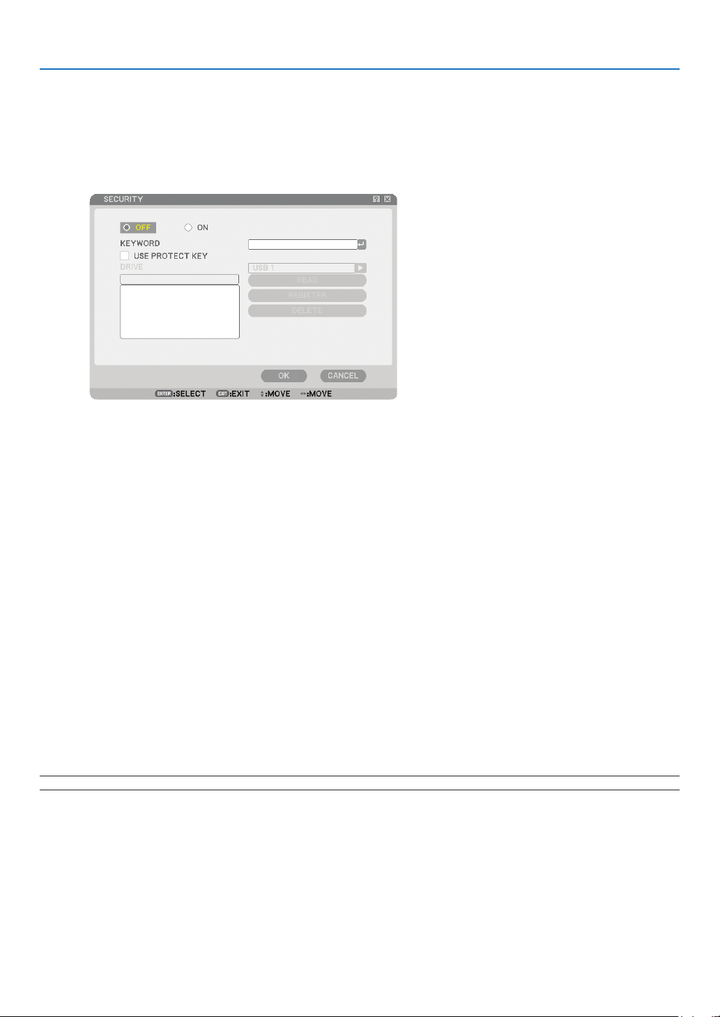
103
6. Using On-Screen Menu
[SECURITY]
The Security function enables you to protect your projector so that the projector will not project a signal unless
you enter a keyword. There is also an option to lock the projector by using a registered USB memory* as a protect
key. Once you have registered your USB memory as a protect key, you are required to insert the registered USB
memory into the USB port of the projector each time you turn on the projector. You can enable the Security func-
tion by using a keyword only. (→ page
41)
* The projector does not support NTFS formatted USB memory device.
Be sure to use a USB memory device formatted with the FAT32, FAT16 or FAT le system.
To format your USB memory device in your computer, refer to the document or help le that comes with your
Windows.
ON/OFF ...............................This turns the Security function on or off. This setting will take effect when the projector is
turned on next time. This setting will take effect when the projector is turned on next time.
KEYWORD..........................Enter an appropriate keyword when you use the Security function. (Up to 10 characters can be
used.) The Security function is available only when your password is entered.
USE PROTECT KEY
..............Check this box to lock your projector when using a USB memory. To use a keyword without a
USB memory, do not check this box.
READ ..................................Reads data from a USB memory.
REGISTER ..........................Registers data from the USB memory. The Security function is not available unless at least one
USB memory is registered. (if the [USE PROTECT KEY] check box is selected) Up to 5 USB
memory devices can be registered.
DELETE ..............................Deletes data of a registered USB memory.
To set up a keyword to enable the Security function without using a registered USB memory.
1.
Use the SELECT ▲ or ▼ button to select [KEYWORD] and use the software keyboard to enter a keyword.
NOTE: Please make a note of your keyword.
2. Use the SELECT ▲ or ▼ button to select [OFF] and then use the SELECT ◀ or ▶ to select [ON].
3. Use the SELECT ▲ or ▼ button to select [OK] , then press the ENTER button.
The [ARE YOU SURE?] message will appear.
4. Use the SELECT ◀ or ▶ button to select [YES] and press the ENTER button.
The Security function takes effect.

104
6. Using On-Screen Menu
To register a USB memory device as a protect key.
Preparation: Insert the USB memory device into the USB port (type A) of the projector.
1. Use the SELECT ▲ or ▼ button to select [USE PROTECT KEY] and press the ENTER button.
2. Use the SELECT ▲ or ▼ button to select [READ] and press the ENTER button.
Data of the USB memory will be read into the projector.
3. Use the SELECT ▲ or ▼ button to select [REGISTER] and press the ENTER button.
Downloaded data will be registered and be displayed in the list window.
4.
Use the SELECT ▲ or ▼ button to select [KEYWORD] and use the software keyboard to enter a keyword.
NOTE: Please make a note of your keyword.
5. Use the SELECT ▲ or ▼ button to select [OFF] and then use the SELECT ◀ or ▶ to select [ON].
6. Use the SELECT ▲ or ▼ button to select [OK] , then press the ENTER button.
The [ARE YOU SURE?] message will appear.
7. Use the SELECT ◀ or ▶ button to select [YES] and press the ENTER button.
The Security function takes effect.
To turn on the projector when Security is enabled (when using your keyword only).
1. Press and hold the POWER button for a minimum of two seconds.
The projector will be turned on and a message to the effect that the projector is security-protected will
be displayed.
2. Press the MENU button.
The Release Code input screen will be displayed.
3. Enter your keyword in the Release Code input screen.
You can view the projected image.
NOTE: Do not forget your keyword. However, if you forget your keyword, NEC or your dealer will provide you with your Release
Code. See more information at the end of this section.
To turn on the projector when Security is enabled (when using USB memory device as a protect key).
Preparation: Insert the registered USB memory device into the USB port (type A) of the projector.
Press and hold the POWER button for a minimum of two seconds.
The projector will turn on and then recognize the USB memory device. Once the image has been projected, it will
stay on without the USB memory device.
• The projector does not support NTFS formatted USB memory device.
Be sure to use a USB memory device formatted with the FAT32, FAT16 or FAT le system.
To format your USB memory device in your computer, refer to the document or help le that comes with your
Windows.
• We do not warrant that the USB port of the projector will support all USB memory devices in the market.
• When the projector is turned on, if the registered USB memory device is not inserted into the projector, no
signal will be displayed with a message to the effect that the projector is security-protected. To turn off the
security protection, insert the registered USB memory device into the projector.

105
6. Using On-Screen Menu
• The security disable mode is maintained until the main power is turned off (by setting the main power switch
to “O” or unplugging the power cord). In the following cases you will be asked to check the protect key or in-
put the password:
(1) When [OK] is selected at an image for which security is set and the power is turned off then back on
(2) When the main power is turned off then back on while the security function is enabled
(3) When you attempt to display an image for which security is set while the security function is enabled
• Blanks (spaces) cannot be used in the Keyword section.
To delete USB memory data you registered.
1.
Use the SELECT ▲ or ▼ button to select [DELETE] and use the SELECT ◀ button to select the list window.
2. Use the SELECT ▲ or ▼ button to select the information on the USB memory device you wish to delete.
3. Press the SELECT ▶ button to select [DELETE] and press the ENTER button.
The information on the USB memory device will be deleted.
If you’ve lost your registered USB memory, proceed as follows:
1. Press and hold the POWER button for a minimum of two seconds.
The projector will be turned on and display a message to the effect that the projector is security-protected.
2. Press the MENU button.
The Release Code input screen will be displayed as well as your Request Code (24 alphanumeric char-
acters).
NOTE: NEC or your dealer will provide you with your Release Code in exchange for your registered keyword and Request Code.
3. Enter your Release Code in the Release Code Input screen.
The security protection will be turned off.
NOTE:
• Some brands of USB memory devices cannot be used as a protect key.
• You should register one or more USB memory devices in case your registered USB memory device is damaged or stolen. Up
to 5 pieces can be registered.
• Once the registered USB memory device has been formatted, the USB memory device cannot be recognized as your regis-
tered protect key.
The Security will not be disabled by using [RESET].

106
6. Using On-Screen Menu
Setting a Password for PJLink [PJLink]
This option allows you to set a password when you use the PJLink feature.
Password: Enter a password (up to 32 characters)
To set and delete a password, repeat steps described in [BACKGROUND LOCK].
NOTE: Do not forget your password. However, if you forget your password, consult with your dealer.
NOTE: What is PJLink?
PJLink is a standardization of protocol used for controlling projectors of different manufacturers. This standard protocol is es-
tablished by Japan Business Machine and Information System Industries Association (JBMIA) in 2005.
The projector supports all the commands of PJLink Class 1.
Setting of PJLink will not be affected even when [RESET] is done from the menu.
Selecting Power-saving in [STANDBY MODE]
The projector has two standby modes: [NORMAL] and [POWER-SAVING].
Power-saving mode is the mode that allows you to put the projector in the power-saving condition which con-
sumes
less power than the Normal mode. The projector is preset for Normal mode at the factory.
NOTE:
• The HTTP server functions are not available during POWER-SAVING mode.
• The MONITOR OUT function is not available during POWER-SAVING mode.
• Control through the PC Control connector and LAN mode is not available during POWER-SAVING mode. For PC control and
LAN mode of the projector it is recommended to leave the projector in the Normal mode.
• When [PROGRAM TIMER] is turned on, the [STANDBY MODE] setting is ignored.
• Your setting will not be affected even when [RESET] is done from the menu.
NORMAL ............... Power indicator: Orange light/Status indicator: Green light
POWER-SAVING ... Power indicator: Orange light/Status indicator: Off
Turning On or Off Remote Sensor [REMOTE SENSOR]
This option determines which remote sensor on the projector is enabled in wireless mode.
The options are: FRONT/BACK, FRONT, and BACK.
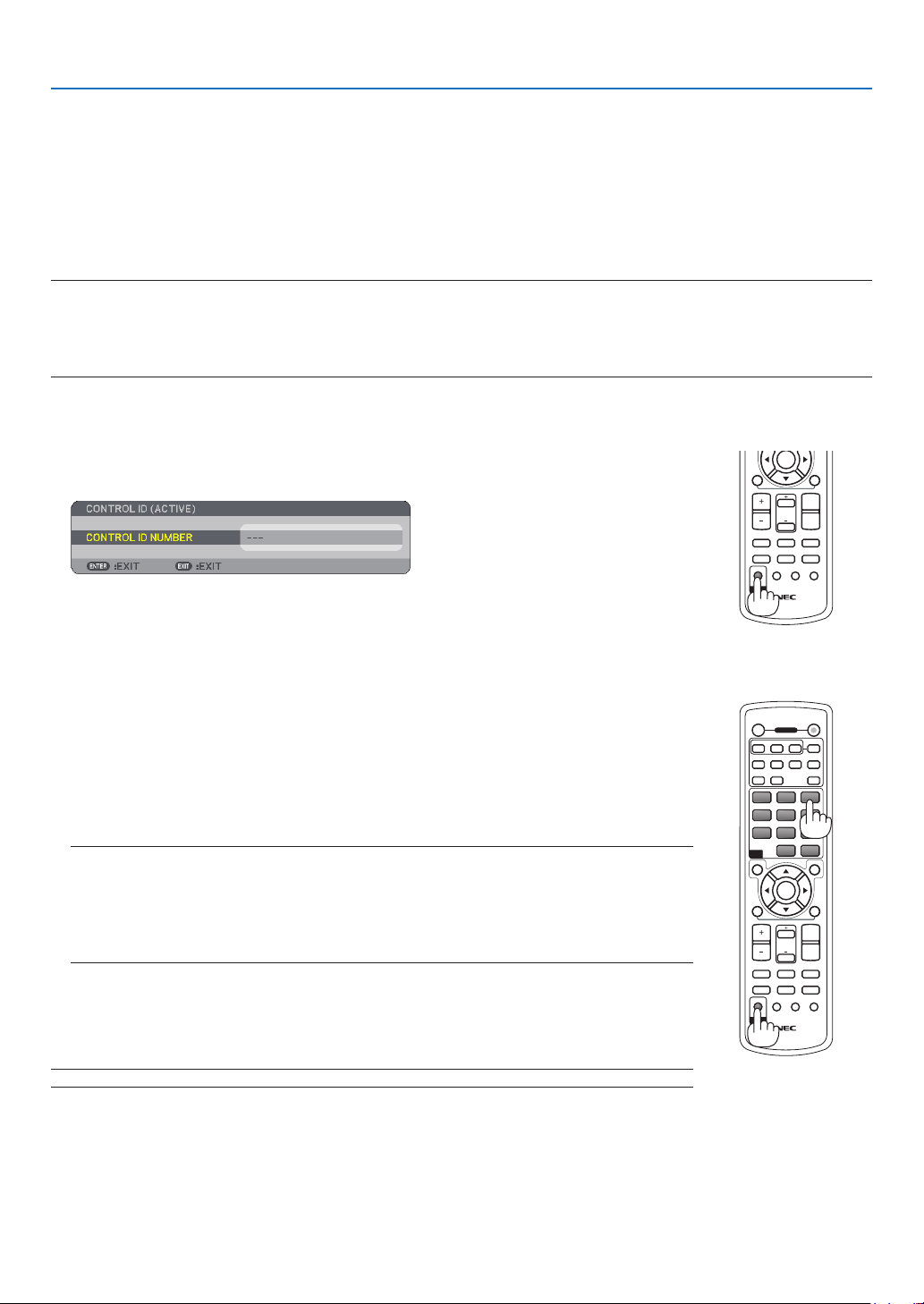
107
6. Using On-Screen Menu
Setting ID to the Projector [CONTROL ID]
You can operate multiple projectors separately and independently with the same single remote control. To do so,
you have to assign an ID number to each projector.
CONTROL ID NUMBER ......Select a number from 1 to 254 you wish to assign to your projector.
CONTROL ID ......................Select [OFF] to turn off the CONTROL ID setting and select [ON] to turn on the CONTROL ID
setting.
NOTE:
• If you select [ON] for [CONTROL ID], you cannot operate the projector from the remote control with a different CONTROL ID.
The buttons on the projector cabinet can be used. Neither can you operate the projector by using the optional remote control
NP01RC that does not has the CONTROL ID function.
• Your setting will not be affected even when [RESET] is done from the menu.
Using the Remote Control to change IDs
1. Press the ID SET button on the remote control.
The CONTROL ID screen will be displayed.
If the projector can be operated with the current remote control ID, the [ACTIVE] will
be displayed. If the projector cannot be operated with the current remote control ID,
the [INACTIVE] will be displayed. To operate the inactive projector, assign the ID by
using the following procedure (Step 2).
2. Press one of 0 to 9 buttons while pressing and holding the ID SET button on the
remote control.
The range of IDs is from 1 to 254.
To clear the ID:
Press the CLEAR button while pressing the ID SET button.
NOTE:
• Setting "0 (zero)" means to clear the ID.
• You cannot operate the projector using the remote control if the remote ID is not the same as
the projector ID.
• No ID means that all the projectors can be operated together with a single remote control. To
set "No ID", enter "000" or press the CLEAR button.
3. Release the ID SET button.
The updated CONTROL ID screen will be displayed.
NOTE: The IDs can be cleared for a few days after the batteries are run down or removed.
MAGNIFYVOLUME
PICTURE
LAMP MODE
ASPECT
AV-MUTE
3D REFORM
FREEZE
ID SET
LENS SHIFT
FOCUS
/ZOOM
HELP
PAGE
L-CLICK
R-CLICK
ENTER
UP
DOWN
ID
OFF ON
COMPUTER
VIDEO S-VIDEO
VIEWER
NETWORK
HDMI
PIP
MAGNIFYVOLUME
PICTURE
LAMP MODE
ASPECT
AV-MUTE
3D REFORM
FREEZE
ID SET
LENS SHIFT
FOCUS
/ZOOM
HELP
PAGE
MENU
L-CLICK
R-CLICK
EXIT
COMPONENT
AUTO ADJ.
ENTER
UP
DOWN
POWER
ID
ID
123
1 32
4 65
7 98
0
CLEAR
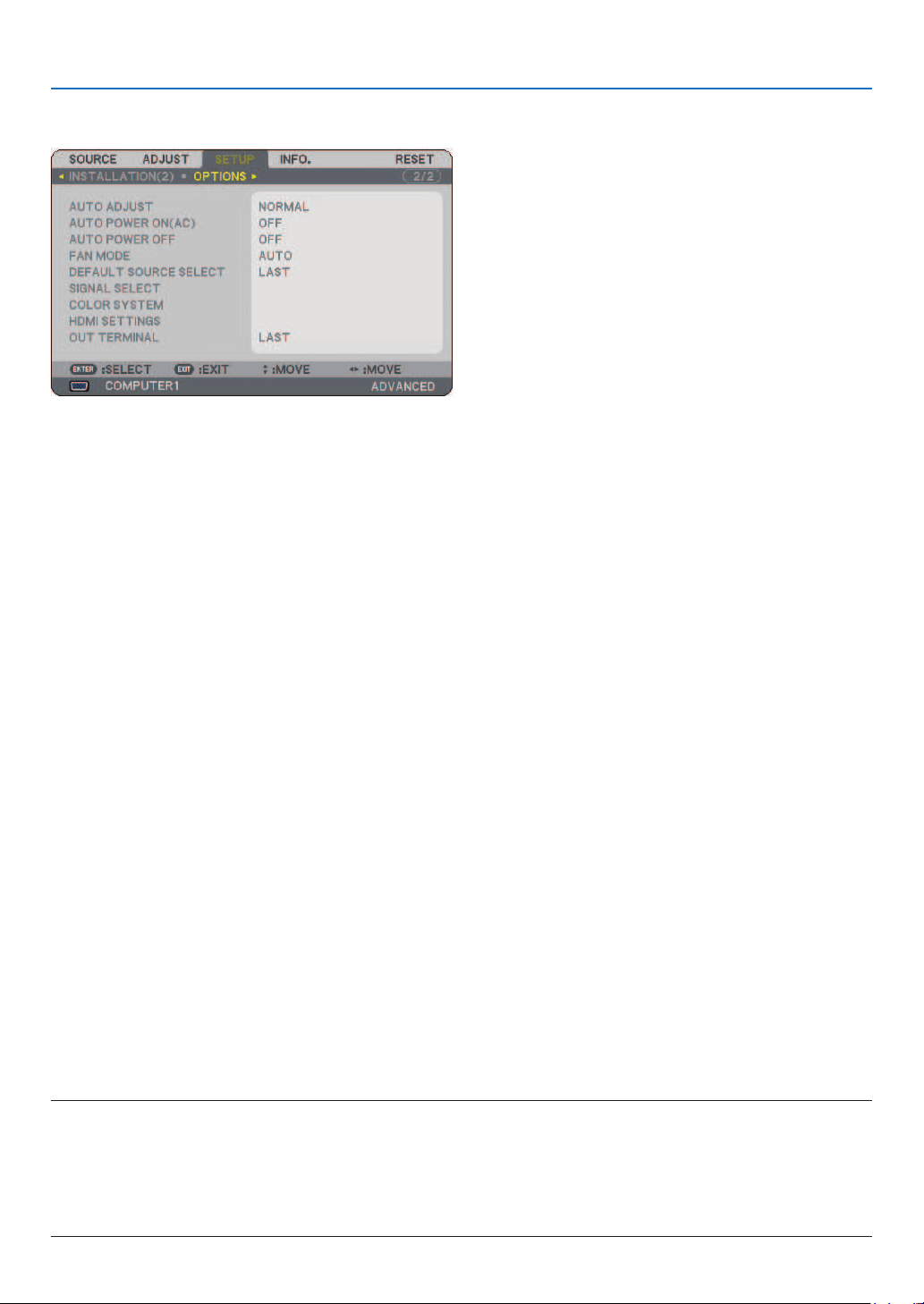
108
6. Using On-Screen Menu
[OPTIONS]
Setting Auto Adjust [AUTO ADJUST]
This feature sets the Auto Adjust mode so that the RGB image can be automatically or manually adjusted for
noise and stability. You can automatically make adjustment in two ways: [NORMAL] and [FINE].
OFF ........................ The RGB image will not be automatically adjusted.
You can manually optimize the RGB image.
NORMAL ............... Default setting. The RGB image will be automatically adjusted. Normally select this option.
FINE ....................... Select this option if fi ne adjustment is needed. It takes more time to switch to the source than when
[NORMAL] is selected.
Enabling Auto Power On [AUTO POWER ON (AC)]
Turns the projector on automatically when the power cable is inserted into an active power outlet and the main
power switch is turned on. This eliminates the need to always use the POWER button on the remote control or
projector cabinet.
To use the AUTO POWER ON (AC) function, you must rst press the main power switch to the position “On” be-
fore plugging in the power cable.
Enabling Power Management [AUTO POWER OFF]
When this option is selected you can enable the projector to automatically turn off (at the selected time: 5min.,
10min., 20min., 30min.) if there is no signal received by any input.
Enabling High Speed Fan Mode [FAN MODE]
This option allows you to select three modes for fan speed: AUTO mode, HIGH speed mode, and HIGH ALTI-
TUDE mode.
AUTO ..................... The built-in fans automatically run at a variable speed according to the internal temperature.
HIGH ...................... The built-in fans run at high speed.
HIGH ALTITUDE .... The built-in fans run at a high speed. Select this option when using the projector at altitudes approxi-
mately 5500 feet/1600 meters or higher.
When you wish to cool down the temperature inside the projector quickly, select [HIGH].
NOTE:
• It is recommended that you select High speed mode if you use the projector non-stop for consecutive days.
• Using the projector at altitudes approximately 5500 feet/1600 meters or higher without setting to [HIGH ALTITUDE] can cause
the projector to overheat and the protector could shut down. If this happens, wait a couple minutes and turn on the projector.
• Using the projector at altitudes less than approximately 5500 feet/1600 meters and setting to [HIGH ALTITUDE] can cause the
lamp to overcool, causing the image to fl icker. Switch [FAN MODE] to [AUTO].
• Your setting will not be affected even when [RESET] is done from the menu.

109
6. Using On-Screen Menu
Selecting Default Source [DEFAULT SOURCE SELECT]
You can set the projector to default to any one of its inputs each time the projector is turned on.
LAST ..................... Sets the projector to default to the previous or last active input each time the projector is turned on.
AUTO ..................... Searches for an active source in order of COMPUTER1 → COMPUTER2 → HDMI → VIDEO → S-VIDEO
→ VIEWER → COMPUTER1 and displays the fi rst found source.
COMPUTER1 ......... Displays the RGB source from the COMPUTER1 IN connector every time the projector is turned on.
COMPUTER2 ......... Displays the RGB source from the COMPUTER2 IN connector every time the projector is turned on.
HDMI ..................... Displays the digital source from the HDMI IN connector every time the projector is turned on.
VIDEO .................... Displays the Video source from the VIDEO IN connector every time the projector is turned on.
S-VIDEO ................ Displays the Video source from the S-VIDEO IN connector every time the projector is turned on.
VIEWER ................. Displays slides from the USB memory device every time the projector is turned on.
NETWORK ............. Displays a signal from LAN port (RJ-45).
Selecting Signal Format [SIGNAL SELECT]
COMPUTER1/2
Allows you to set [COMPUTER1] and [COMPUTER2] to automatically detect an incoming RGB or component
source such as a computer or DVD player. However there may be some RGB and component signals that the
projector is unable to detect. In this case, select [RGB].
Selecting [COLOR SYSTEM]
This feature enables you to select video standards manually.
Normally select [AUTO]. Select the video standard from the pulldown menu. This must be done for Video and
S-Video Connectors separately.
Setting HDMI [HDMI SETTINGS]
Make the settings for video level and audio level when connecting HDMI equipment such as a DVD player.
VIDEO LEVEL ........ Select [NORMAL] to disable the [ENHANCED] feature of your HDMI equipment. Select [ENHANCED] to
improve image contrast and increase detail in the dark areas.
AUDIO SELECT ...... Select [HDMI] to switch the HDMI IN digital audio signal and select [COMPUTER2] to switch the COM-
PUTER2 input audio signal.
Setting MONITOR OUT Connector [OUT TERMINAL]
This option allows you to determine which RGB or component source is output from the MONITOR OUT and the
AUDIO OUT connectors during Standby mode.
LAST ..................... The video and audio signal from the last COMPUTER1 or COMPUTER2 input will be output to the MON-
ITOR OUT connector.
COMPUTER1, 2 ..... The video and audio signal from the COMPUTER1 or COMPUTER2 input will be output to the MONITOR
OUT connector.
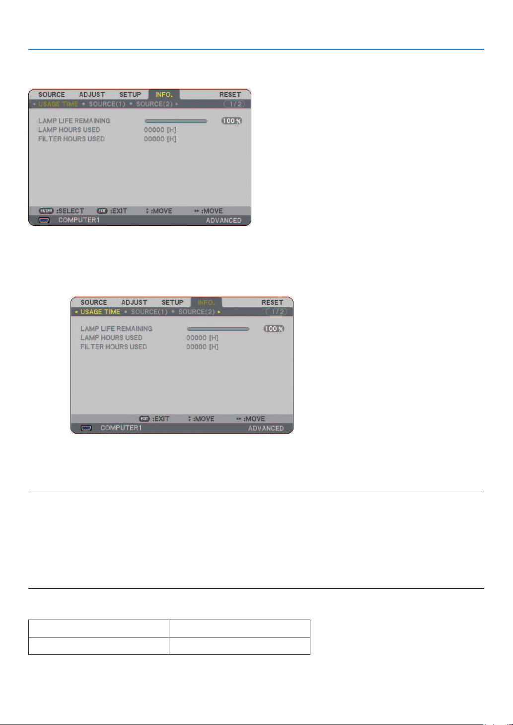
110
6. Using On-Screen Menu
❼
Menu Descriptions & Functions [INFO.]
Displays the lamp usage hours, the status of the current signal and settings, NETWORK settings and version.
The information included are as follows:
[USAGE TIME]
LAMP LIFE REMAINING (%)
LAMP HOURS USED (H)
FILTER HOURS USED (H)
NOTE: The progress indicator shows the percentage of remaining lamp life. The value informs you of the amount of lamp and
fi lter usage respectively.
• When the remaining lamp time reaches 0, the Lamp Life Remaining bar indicator changes from 0% to 600 Hours and the
countdown starts.
If lamp life remaining time reaches 0 hours, the projector will not turn on regardless of whether the lamp mode is set to Nor-
mal or Eco.
•
The message to the effect that the lamp should be replaced will be displayed for one minute when the projector is turned on or
off.
To dismiss this message, press any button on the projector or the remote control.
Lamp Life
NORMAL ECO
2500 Hours (Min.) 3500 Hours (Max.)
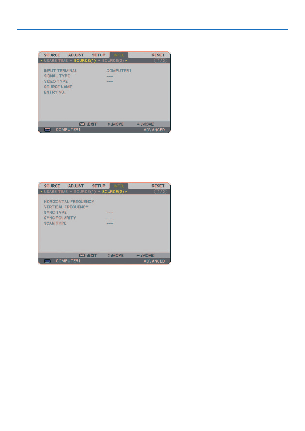
111
6. Using On-Screen Menu
[SOURCE(1)]
INPUT TERMINAL SIGNAL TYPE
VIDEO TYPE SOURCE NAME
ENTRY NO.
[SOURCE(2)]
HORIZONTAL FREQUENCY
VERTICAL FREQUENCY
SYNC TYPE SYNC POLARITY
SCAN TYPE
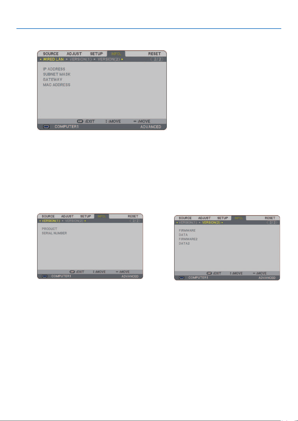
112
6. Using On-Screen Menu
[WIRED LAN]
This page shows information on settings for the LAN port (RJ-45)
IP ADDRESS .......... Indicates the IP address of the projector when the LAN port (RJ-45) is used.
SUBNET MASK...... Indicates the subnet mask of the projector when the LAN port (RJ-45) is used.
GATEWAY .............. Indicates the gateway of the network connected to the projector when the LAN port (RJ-45) is used.
MAC ADDRESS ..... Indicates the MAC address of the LAN port (RJ-45).
[VERSION(1)]
PRODUCT
SERIAL NUMBER
CONTROL ID (optional)
[VERSION(2)]
FIRMWARE
DATA
FIRMWARE2
DATA2
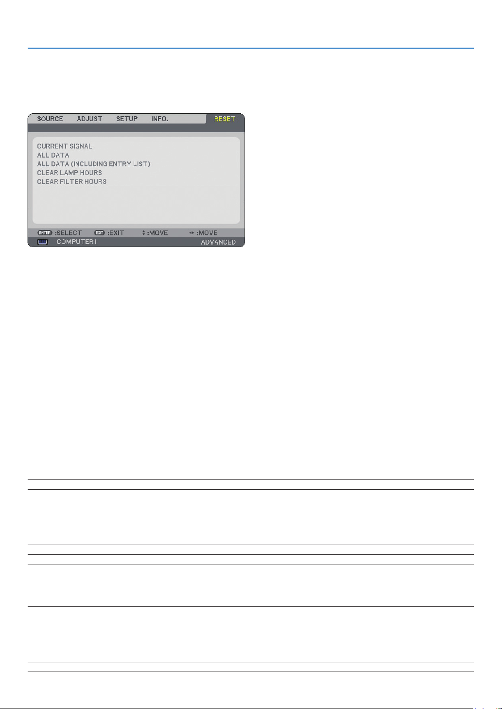
113
6. Using On-Screen Menu
❽
Menu Descriptions & Functions [RESET]
Returning to Factory Default
The Reset feature allows you to change adjustments and settings to the factory preset for sources by the following
methods:
[CURRENT SIGNAL]
Resets the adjustments for the current signal to the factory preset levels.
All the items in [ADJUST] can be reset.
[ALL DATA]
Reset all the adjustments and settings for all the signals to the factory preset except [ENTRY LIST], [LAN-
GUAGE], [BACKGROUND], [FILTER MESSAGE], [SECURITY SETTINGS], [NETWORK SETTINGS], [COM-
MUNICATION SPEED], [STANDBY MODE], [CONTROL ID], [FAN MODE], [DATE, TIME PRESET], [LAMP
LIFE REMAINING], [LAMP HOURS USED] and [FILTER HOURS USED].
[ALL DATA (INCLUDING ENTRY LIST)]
Reset all the adjustments and settings for all the signals to the factory preset except [LANGUAGE], [BACK-
GROUND], [FILTER MESSAGE], [SECURITY SETTINGS], [NETWORK SETTINGS], [COMMUNICATION
SPEED], [STANDBY MODE], [CONTROL ID], [FAN MODE], [DATE, TIME PRESET], [LAMP LIFE REMAIN-
ING], [LAMP HOURS USED] and [FILTER HOURS USED].
Also deletes all the signals in the [ENTRY LIST] and returns to the factory preset.
NOTE: Locked signals in Entry List cannot be reset.
Clearing Lamp Hour Meter [CLEAR LAMP HOURS]
Resets the lamp clock back to zero.
NOTE: Elapsed time of the lamp use will not be affected even when [RESET] is done from the menu.
NOTE: The projector will turn off and go into standby mode when you continue to use the projector for another 600 hours after
the lamp has reached the end of its life. In this condition you cannot clear the lamp hour meter on the menu. If this happens,
press the HELP button on the remote control for 10 seconds to reset the lamp clock back to zero. Do this only after replacing the
lamp.
Resetting the Filter Usage Hours [CLEAR FILTER HOURS]
Resets the lter usage back to zero.
NOTE: Elapsed time of the fi lter use will not be affected even when [RESET] is done from the menu.
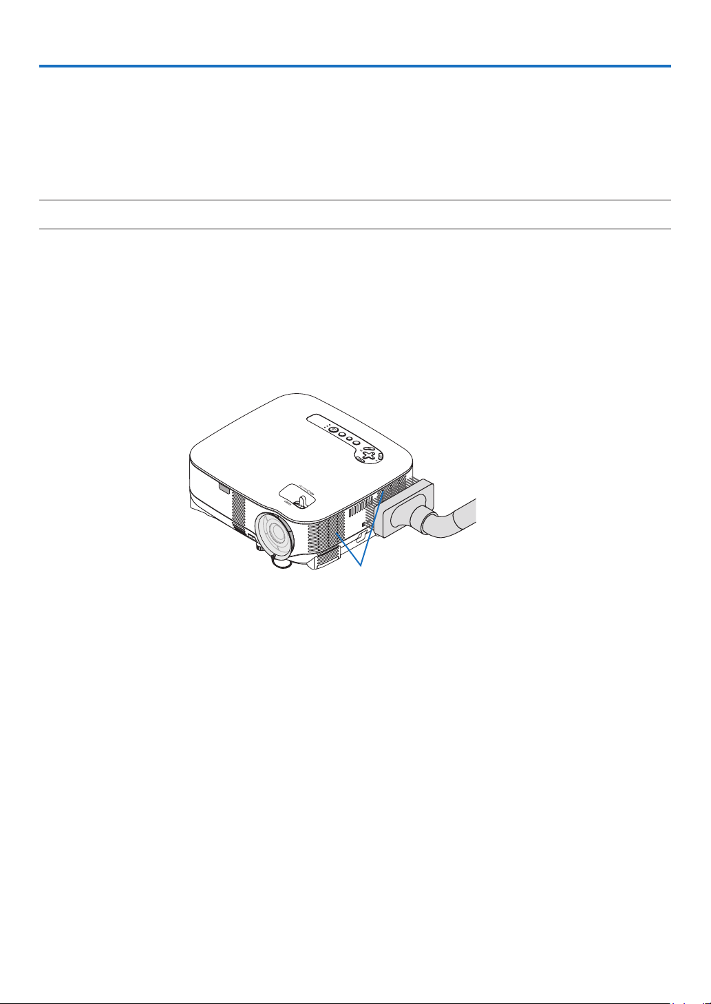
114
7. Maintenance
This section describes the simple maintenance procedures you should follow to clean the lters and replace the
lamp.
❶
Cleaning or Replacing the Filter
The air- lter sponge keeps dust and dirt from getting inside the projector and should be frequently cleaned. If the
lter is dirty or clogged, your projector may overheat.
NOTE: The message for fi lter cleaning will be displayed for one minute when the projector is turned on or off.
To cancel the message, press any button on the projector cabinet or the remote control.
CAUTION
• Turn off the projector, turn off the main power switch and unplug the projector before replacing the lter.
• Only clean the outside of the lter cover with a vacuum cleaner.
• Do not attempt to operate the projector without the lter cover.
To clean the air- lter:
Vacuum the lter-through the lter cover.
To reset the lter usage time, from the menu, select [RESET] → [CLEAR FILTER HOURS].
(→ page
113 for resetting the lter usage time)
USB
LA
MP
S
TATUS
SOURCE
AUTO ADJUST
3D REFORM
SELECT
Filter
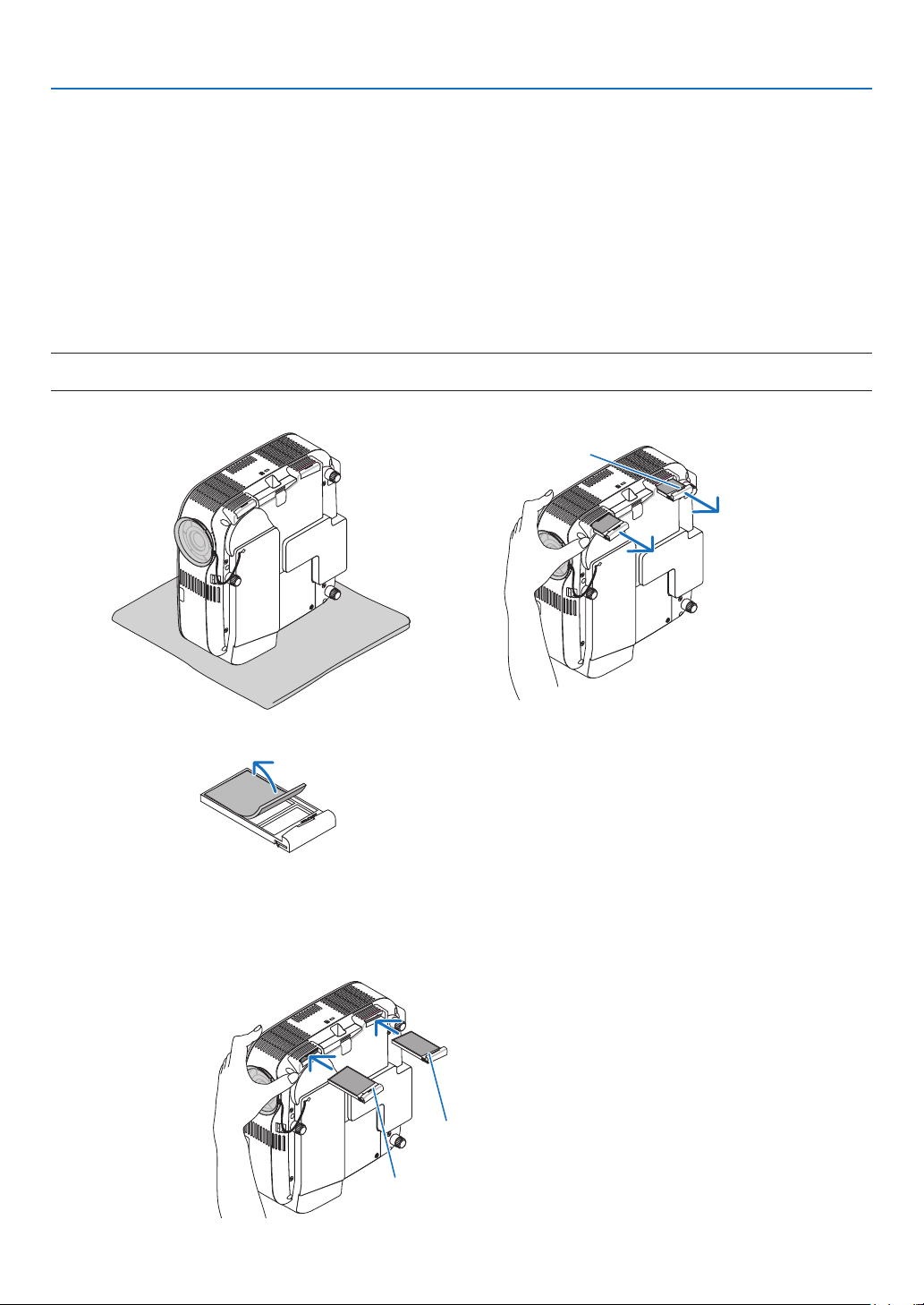
115
7. Maintenance
To replace the lter (sponge):
CAUTION
• Replace both lters at the same time.
• Before replacing the lters, remove dust and dirt from the projector cabinet.
• The projector contains high-precision parts. Keep out dust and dirt during lter replacement.
• Do not wash the lter with water. Water will damage the lter membrane.
• Reattach the lter cover correctly. Failure to do so may cause projector malfunction.
Preparation: Replace the lamp before replacing the lters.
NOTE: When you replace the lamp, it is also wise to replace the fi lter. The fi lter comes in the same package with your replacement
lamp.
1. Remove the filter cover by pushing down on the catch of the cover until you feel it detach.
Catch
2. Gently peel off the filter (sponge) and replace it with the new one.
The filter is attached with self-adhesive tape. Peel off the release paper before use.
3. Reinstall the new filter cover.
• Slip the lter cover back until it snaps into place.
Front
Rear
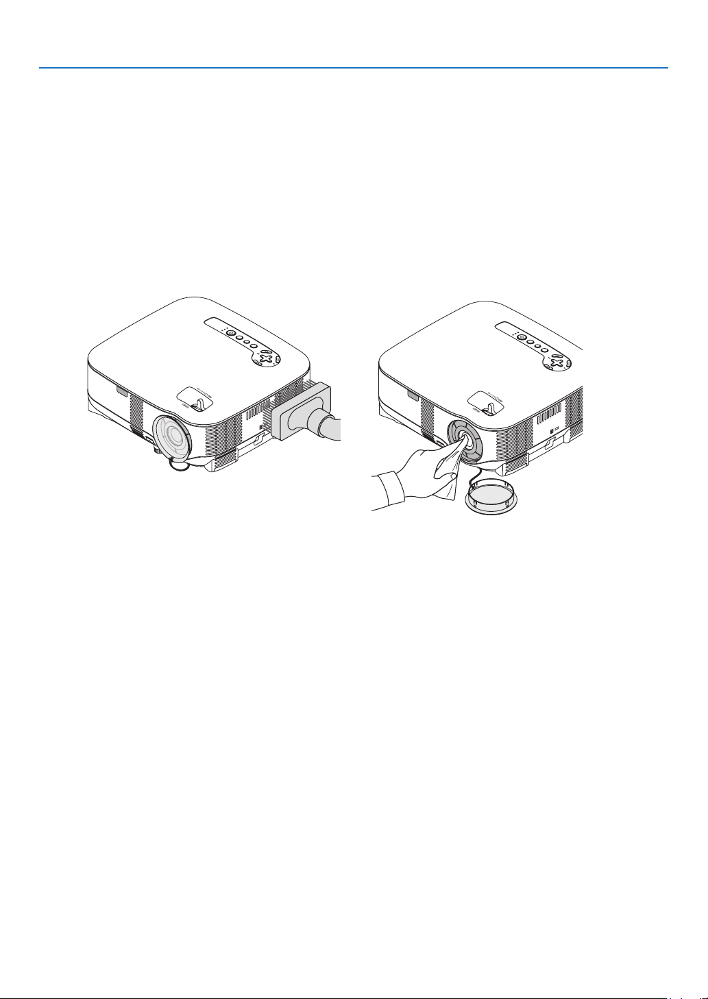
116
7. Maintenance
USB
LAMP
STATUS
SOUR
CE
AUTO ADJUST
3D REFORM
SELEC
T
USB
LAMP
STA
TUS
SOURCE
AUTO ADJUST
3D REFORM
SELECT
❷
Cleaning the Cabinet and the Lens
1. Turn off the projector before cleaning.
2. Clean the cabinet periodically with a damp cloth. If heavily soiled, use a mild detergent. Never use
strong detergents or solvents such as alcohol or thinner.
3. Use a blower or lens paper to clean the lens, and be careful not to scratch or mar the lens.
4. Connect the supplied power cable, turn on the Main Power switch and turn on the projector.
5. Finally, select the menu → [RESET] → [CLEAR FILTER HOURS] to reset the filter usage hours.
(→ page
113 for resetting the filter usage time)
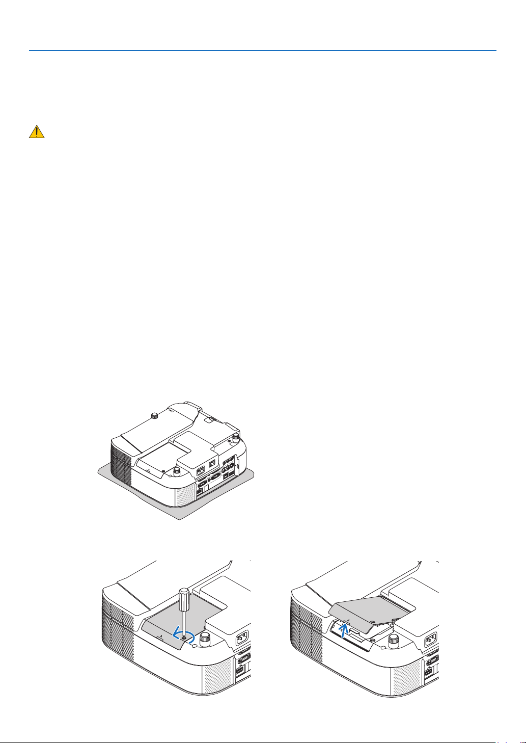
117
7. Maintenance
❸
Replacing the Lamp
When the lamp reaches the end of its life, the LAMP indicator in the cabinet will blink red. Even though the lamp
may still be working, replace the lamp to maintain the optimal projector performance. After replacing the lamp, be
sure to clear the lamp hour meter. (→ page
113)
CAUTION
• DO NOT TOUCH THE LAMP immediately after it has been used. It will be extremely hot. Turn the projector off,
wait 30 seconds, turn off the main power switch and then disconnect the power cable. Allow at least one hour
for the lamp to cool before handling.
• DO NOT REMOVE ANY SCREWS except one lamp cover screw and two lamp housing screws. You could re-
ceive an electric shock.
• Do not break the glass on the lamp housing.
Keep nger prints off the glass surface on the lamp housing. Leaving nger prints on the glass surface might
cause an unwanted shadow and poor picture quality.
•
The projector will turn off and go into standby mode when you continue to use the projector for another 600 hours
after the lamp has reached the end of its life. If this happens, be sure to replace the lamp. If you continue to use
the lamp after the lamp reaches the end of its life, the lamp bulb may shatter, and pieces of glass may be scat-
tered in the lamp case. Do not touch them as the pieces of glass may cause injury. If this happens, contact your
NEC dealer for lamp replacement.
To replace the lamp:
Optional lamp and tools needed for replacement:
• Replacement lamp NP05LP
• Phillips screwdriver or equivalent
1. Place the projector on a soft cloth and turn it over to access the lamp cover on the bottom.
VIDEO IN
AUDIO IN
USB
LAN
AUDIO IN
HDMI IN
AUDIO IN
COMPUTER /
COMPONENT 2 IN
COMPUTER /
COMPONENT 1 IN
PC CONTROL
MONITOR OUT
AUDIO OUT
S-VIDEO IN
AUDIO IN
L/MONO
L/MONO
R
R
2. Use a Philips screwdriver to loosen the lamp cover screw and remove the lamp cover.
AUDIO IN
HDMI IN
COMPUTER /
COMPONENT 2 IN
PC CONTROL
AUDIO IN
HDMI IN
COMPUTER /
COMPONENT 2 IN
PC CONTROL
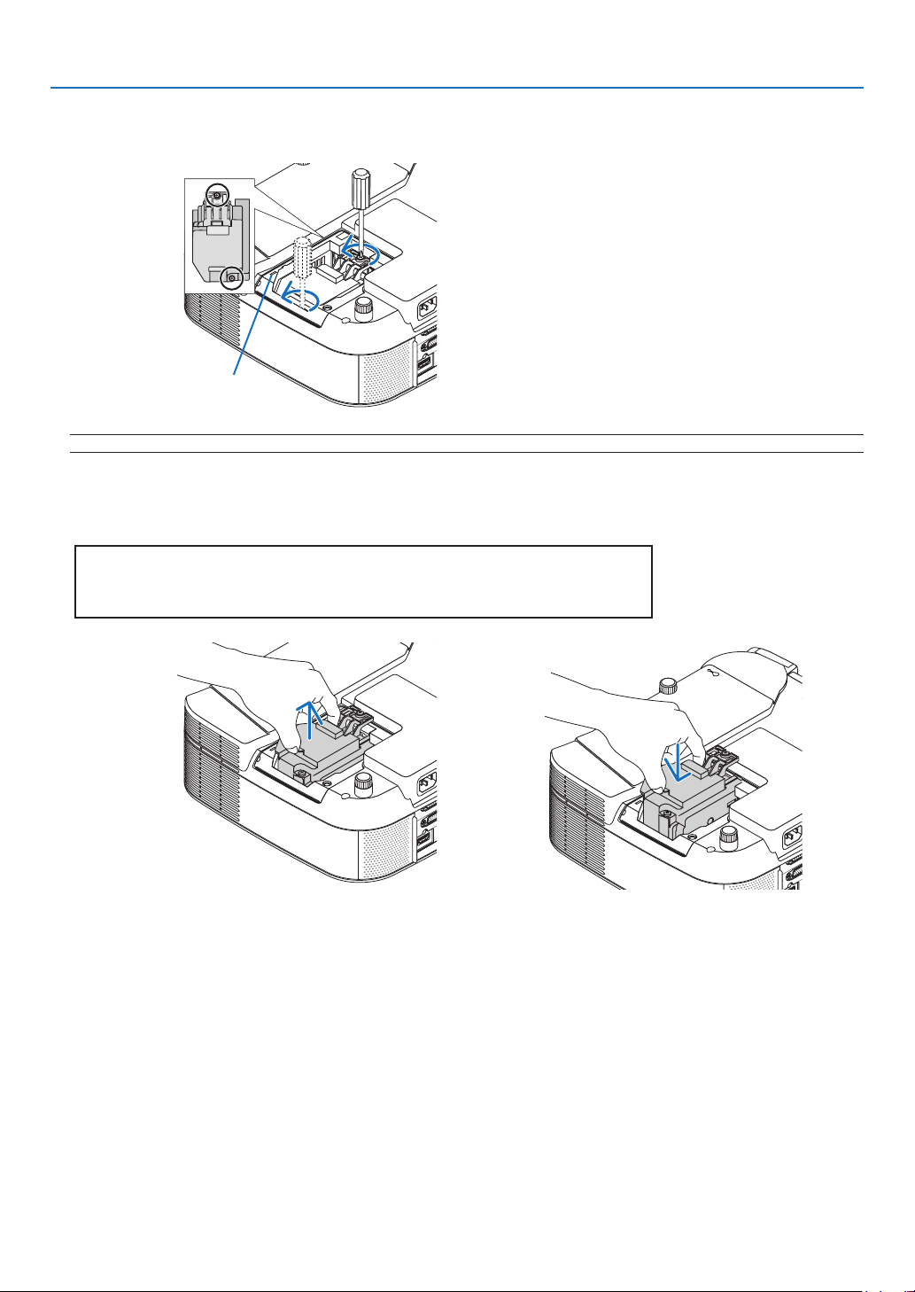
118
7. Maintenance
3. Loosen the two screws securing the lamp housing until the phillips screwdriver goes into a freewheel-
ing condition. The two screws are not removable.
NOTE: There is an interlock on this case to prevent the risk of electrical shock. Do not attempt to circumvent this interlock.
AUDIO IN
HDMI IN
O
MPUTER /
M
PONENT 2 IN
C
CONTROL
Interlock
AUDIO IN
HDMI IN
O
MPUTER /
M
PONENT 2 IN
C
CONTROL
AUD
IO
IN
O
MPUTER /
M
PONENT 2 IN
C
CONTROL
4. Remove the lamp housing by holding it.
Insert a new lamp housing until the lamp housing is plugged into the socket.
CAUTION
Do not use a lamp other than the NEC replacement lamp NP05LP.
Order this from your NEC dealer.
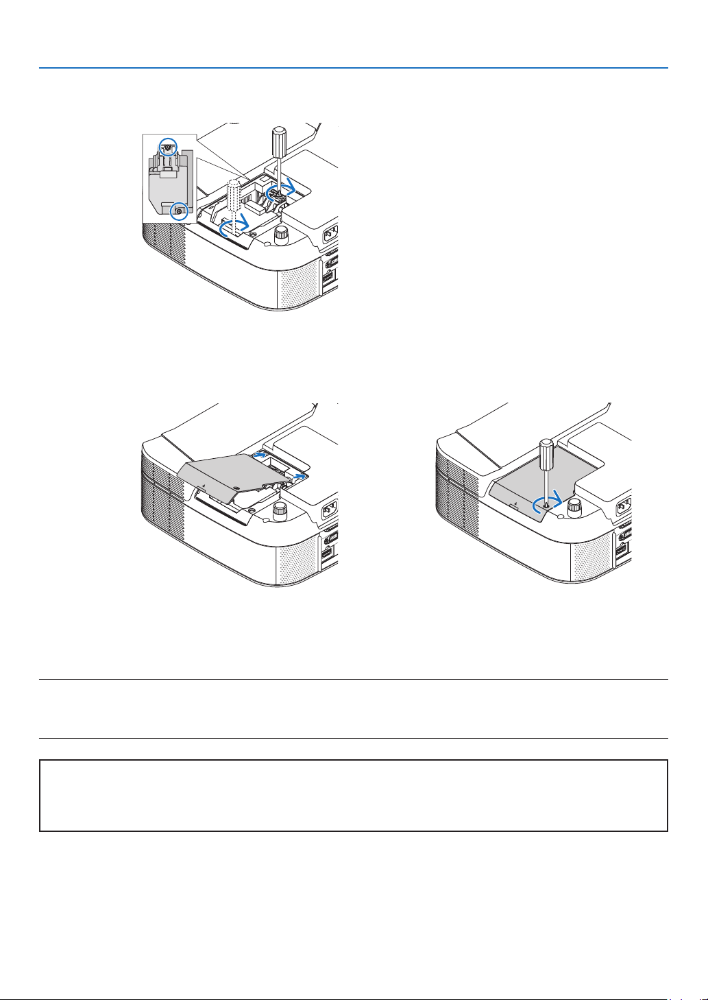
119
7. Maintenance
7. Connect the supplied power cable, turn on the Main Power switch and turn on the projector.
8. Finally, select the menu → [RESET] → [CLEAR LAMP HOURS] to reset the lamp life remaining and lamp
usage hours.
NOTE: When you continue to use the projector for another 600 hours after the lamp has reached the end of its life, the projector
cannot turn on and the menu is not displayed.
If this happens, press the HELP button on the remote control for 10 seconds to reset the lamp clock back to zero.
When the lamp time clock is reset to zero, the LAMP indicator goes out.
5. Secure it in place with the two screws.
Be sure to tighten the screws.
Note for US Residents
The lamp in this product contains mercury. Prease dispose according to Local,
State or Federal Laws.
AUDIO IN
HDMI IN
O
MPUTER /
M
PONENT 2 IN
C
CONTROL
AUDIO IN
HDMI IN
COMPUTER /
O
MPONENT 2 IN
PC CONTROL
6. Reattach the lamp cover.
Slip the lamp cover back until it snaps into place.
Tighten the lamp cover screw.
Be sure to tighten the screw.
AUDIO IN
HDMI IN
OMPUTER /
M
PONENT 2 IN
C
CONTROL
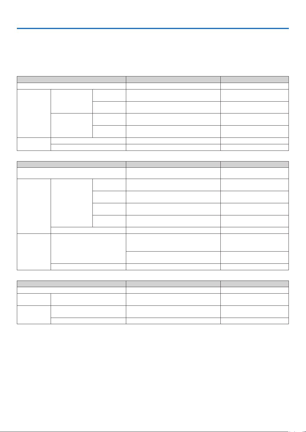
120
8. Appendix
❶
Troubleshooting
This section helps you resolve problems you may encounter while setting up or using the projector.
Indicator Messages
Power Indicator
Indicator Condition Projector Condition Note
Off The main power is off. –
Blinking light
Green
0.5 sec On,
0.5 sec Off
The projector is getting ready to turn on. Wait for a moment.
2.5 sec On,
0.5 sec Off
Off Timer (Off Time) is activated. –
Orange
0.5 sec On,
0.5 sec Off
The projector is cooling down. Wait for a moment.
2.5 sec On,
0.5 sec Off
The Program Timer is activated. –
Steady light
Green The projector is turned on. –
Orange The projector is in Standby. –
Status Indicator
Indicator Condition Projector Condition Note
Off
Normal or Standby ([POWER-SAVING] for [STANDBY
MODE])
–
Blinking light
Red
1 cycle (0.5 sec
On, 2.5 sec Off)
Lamp cover error
Reattach the lamp cover correctly.
(→ page
119)
2 cycle (0.5 sec
On, 0.5 sec Of)
Temperature error
The projector is overheated. Move
the projector to a cooler location.
4 cycle (0.5 sec
On, 0.5 sec Off)
Fan error Fans will not work correctly.
6 cycle (0.5 sec
On, 0.5 sec Off)
Lamp error
Lamp fails to light. Wait a full min-
ute and then turn on again.
Green Re-fi ring the lamp The projector is re-fi ring.
Steady light
Orange
Control Panel Lock is on
You have pressed cabinet button
when Control Panel Lock is on.
(→ page
101)
CONTROL ID error
Remote control ID and projector ID
are not matched.
Green
Standby ([NORMAL] for [STANDBY MODE])
–
Lamp Indicator
Indicator Condition Projector Condition Note
Off Normal –
Blinking light Red
Lamp has reached its end of life. Lamp replace-
ment message will be displayed.
Replace the lamp.
(
→
page 117)
Steady light
Red
Lamp has been used beyond its limit. The projec-
tor will not turn on until the lamp is replaced.
Replace the lamp.
(
→
page 117)
Green Lamp is in Eco mode –
Over-Temperature Protection
If the temperature inside the projector rises too high, the over-temperature protector will automatically turn off the
lamp with the STATUS indicator blinking (2-cycle On and Off.)
Should this happen, do the following:
• Unplug the power cable after the cooling fans stop.
• Move the projector to a cooler location if the room where you are presenting is particularly too warm.
• Clean the ventilation holes if they are clogged with dust.
• Wait about 60 minutes until the inside of the projector becomes cool enough.
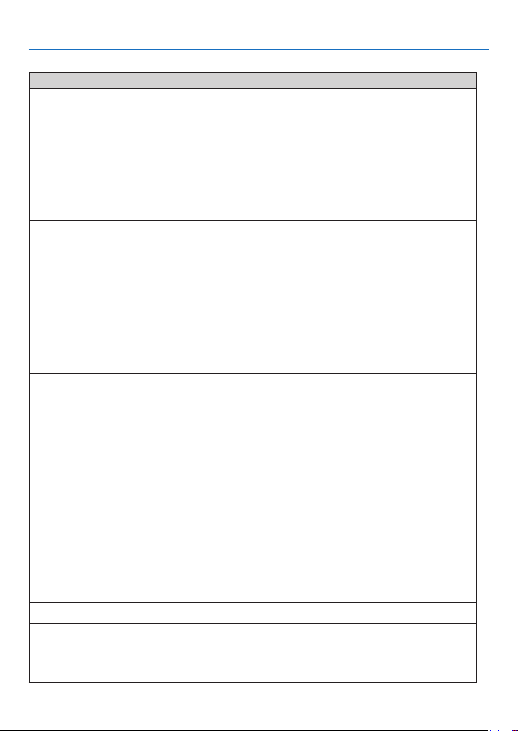
121
8. Appendix
Common Problems & Solutions (→ “Power/Status/Lamp Indicator” on page
120)
Problem Check These Items
Does not turn on • Check that the power cable is plugged in and that the power button on the projector cabinet or the remote
control is on. (→ page
19, 20)
• Ensure that the lamp cover is installed correctly. (→ page 119)
• Check to see if the projector has overheated. If there is insuffi cient ventilation around the projector or if the
room where you are presenting is particularly warm, move the projector to a cooler location.
• Check to see if you continue to use the projector for another 600 hours after the lamp has reached the end
of its life. If so, replace the lamp.
After replacing the lamp, reset the lamp hours used. (→ page 113)
• The lamp may fail to light. Wait a full minute and then turn on the power again.
• Set [FAN MODE] to [HIGH ALTITUDE] when using the projector at altitudes approximately 5500 feet/1600
meters or higher. Using the projector at altitudes approximately 5500 feet/1600 meters or higher without
setting to [HIGH ALTITUDE] can cause the projector to overheat and the projector could shut down. If this
happens, wait a couple minutes and turn on the projector. (→ page 108)
Also when the lamp is turned off, the projector internal temperature is hot. If the power is turned on before
the projector has cooled down, the fan will run a short time before the lamp will turn on.
Will turn off •
Ensure that the [OFF TIMER], [PROGRAM TIMER] or [AUTO POWER OFF] is off
. (→ page
87, 108)
No picture • Use the SOURCE button on the projector cabinet or the VIDEO, the S-VIDEO, the COMPUTER1, the COM-
PUTER2, the HDMI, the VIEWER or the NETWORK button on the remote control to select your source. (→
page
22)
• Ensure your cables are connected properly.
• Use menus to adjust the brightness and contrast. (→ page 77)
• Check to see if the image is muted. (→ page 31)
• Remove the lens cap.
• Reset the settings or adjustments to factory preset levels using the Reset in the Menu. (→ page 113)
• Enter your registered keyword if the Security function is enabled. (→ page 41)
• Be sure to connect the projector and notebook PC while the projector is in standby mode and before turn-
ing on the power to the notebook PC.
In most cases the output signal from the notebook PC is not turned on unless connected to the projector
before being powered up.
* If the screen goes blank while using your remote control, it may be the result of the computer’s screen-
saver or power management software.
• See also the next page.
Color tone or hue is
unusual
•
Check if an appropriate color is selected in [WALL COLOR]. If not, select an appropriate option. (→ page 86)
• Adjust [HUE] in [ADJUST]. (→ page 77)
Image isn’t square to
the screen
• Reposition the projector to improve its angle to the screen. (→ page
23)
• Use the 3D Reform function to correct the trapezoid distortion. (→ page 26)
Picture is blurred • Adjust the focus. (→ page
24)
• Reposition the projector to improve its angle to the screen. (→ page 23)
• Ensure that the distance between the projector and screen is within the adjustment range of the lens. (→
page 126)
• Condensation may form on the lens if the projector is cold, brought into a warm place and is then turned
on. Should this happen, let the projector stand until there is no condensation on the lens.
Flicker appears on
screen
• Set [FAN MODE] to other than [HIGH ALTITUDE] mode when using the projector at altitudes approximately
5500 feet/1600 meters or lower. Using the projector at altitudes less than approximately 5500 feet/1600
meters and setting to [HIGH ALTITUDE] can cause the lamp to overcool, causing the image to flicker.
Switch [FAN MODE] to [AUTO]. (→ page
108)
Image is scrolling
vertically, horizontally or
both
• Use the SOURCE button on the projector cabinet or the VIDEO, the S-VIDEO, the COMPUTER1, the COM-
PUTER2, the HDMI, the VIEWER or the NETWORK button on the remote control to select your source (Video,
S-Video, Computer, Component, Viewer or NETWORK). (→ page
22)
•
Adjust the computer image manually with the [CLOCK]/[PHASE] in [ADJUST] → [IMAGE OPTIONS]. (→ page 78)
Remote control does
not work
• Install new batteries. (→ page 9)
• Make sure there are no obstacles between you and the projector.
• Stand within 22 feet (7 m) of the projector. (→ page 9)
• Check if one or more remote sensors are enabled. Select [SETUP] → [INSTALLATION(2)] → [REMOTE
SENSOR] from the menu. (→ page 106)
• Make sure that the remote control’s ID corresponds with the projector’s ID.
Indicator is lit or blink-
ing
• See the POWER/STATUS/LAMP Indicator. (→ page
120)
Vertical stripes in RGB
mode
• Press the AUTO ADJUST button on the projector cabinet or the AUTO ADJ. button on the remote control. (→
page
28)
•
Adjust the computer image manually with the [CLOCK]/[PHASE] in [ADJUST] → [IMAGE OPTIONS]. (→ page 78)
USB mouse does not
work
• Make sure that your USB mouse is properly connected to the projector. (→ page 33)
The projector may not support some brands of a USB mouse.
• Some menu items cannot be operated with a USB mouse.
For more information contact your dealer.

122
8. Appendix
If there is no picture, or the picture is not displayed correctly.
• Power on process for the projector and the PC.
Be sure to connect the projector and notebook PC while the projector is in standby mode and before turning
on the power to the notebook PC.
In most cases the output signal from the notebook PC is not turned on unless connected to the projector be-
fore being powered up.
NOTE: You can check the horizontal frequency of the current signal in the projector’s menu [SOURCE(2)] under Information.
If it reads “0kHz”, this means there is no signal being output from the computer. See page
111 or go to next step.
• Enabling the computer’s external display.
Displaying an image on the notebook PC’s screen does not necessarily mean it outputs a signal to the projec-
tor. When using a PC compatible laptop, a combination of function keys will enable/disable the external dis-
play. Usually, the combination of the ‘Fn” key along with one of the 12 function keys gets the external display
to come on or off. For example, NEC laptops use Fn + F3, while Dell laptops use Fn + F8 key combinations to
toggle through external display selections.
• Non-standard signal output from the computer
If the output signal from a notebook PC is not an industry standard, the projected image may not be displayed
correctly. Should this happen, deactivate the notebook PC’s LCD screen when the projector display is in use.
Each notebook PC has a different way of deactivate/reactivate the local LCD screens as described in the pre-
vious step. Refer to your computer’s documentation for detailed information.
• Image displayed is incorrect when using a Macintosh
When using a Macintosh with the projector, set the DIP switch of the Mac adapter (not supplied with the pro-
jector) according to your resolution. After setting, restart your Macintosh for the changes to take affect.
For setting display modes other than those supported by your Macintosh and the projector, changing the DIP
switch on a Mac adapter may bounce an image slightly or may display nothing. Should this happen, set the
DIP switch to the 13” xed mode and then restart your Macintosh. After that, restore the DIP switches to a dis-
playable mode and then restart the Macintosh again.
NOTE: A Video Adapter cable manufactured by Apple Inc. is needed for a PowerBook which does not have a mini D-Sub
15-pin connector.
• Mirroring on a PowerBook
* When using the projector with a Macintosh PowerBook, output may not be set to 1024 x 768 unless “mirroring”
is off on your PowerBook. Refer to owner’s manual supplied with your Macintosh computer for mirroring.
• Folders or icons are hidden on the Macintosh screen
Folders or icons may not be seen on the screen. Should this happen, select [View] → [Arrange] from the Apple
menu and arrange icons.
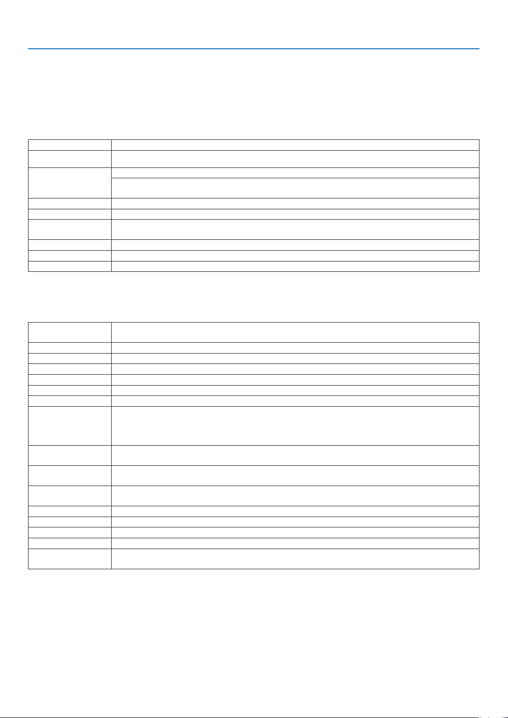
123
8. Appendix
❷
Specifi cations
This section provides technical information about the projector’s performance.
Model Number VT800
Optical
LCD Panel 0.63 inch LCD with Micro Lens Array (Aspect Ratio 4:3)
Resolution 1024 x 768 pixels*
Lens
Manual zoom and focus
Zoom Ratio= 1-1.2
F1.70 - 2.07 f= 18.9 - 22.7 mm
Lamp 210W AC (172W in ECO Mode)
Light Output 2700 lumens (approx. 80% in ECO Mode)
Contrast Ratio
(full white: full black)
500:1
Image Size (Diagonal) 21" - 300"/ 0.53 m - 7.62 m
Projection Distance 29 - 424 inches/0.73 - 10.8 m
Projection Angle Tele: 8.3° - 8.6°/Wide: 9.9° - 10.3°
* Effective pixels are more than 99.99%.
Electrical
Inputs
2 Analog RGB (Mini D-Sub 15P), 1 HDMI (19P)**, 1 S-Video (Mini DIN 4P), 1 Video (RCA),
2 Stereo Mini Audio, 2 (L/R) RCA Audio
Outputs 1 RGB (Mini D-Sub 15P), 1 Stereo Mini Audio
PC Control 1 PC Control Port (D-Sub 9P)
USB Port 1 A Type
LAN Port RJ-45
External Control RS232, IR, LAN
Color Reproduction 10-bit signal processing (1.07 billion)
Compatible Signals***
Analog: VGA/SVGA/XGA/WXGA/WXGA+/SXGA/SXGA+/UXGA
480i/480p/576i/576p/720p/1080i/1080p
Digital: VGA/SVGA/XGA/WXGA/WXGA+/SXGA/SXGA+
480p/576p/720p/1080i/1080p
Video Bandwidth
Analog: 165MHz (max.)
Digital: 150MHz (max.)
Horizontal Resolution
540 TV lines: NTSC/NTSC4.43/PAL/PAL-M/PAL-N/PAL60
300 TV lines: SECAM
Scan Rate
Horizontal: 15 kHz to 108 kHz (RGB: 24 kHz or over)
Vertical: 48 Hz to 120 Hz
Sync Compatibility Separate Sync / Composite Sync / Sync on G
Built-in Speaker 5W (monaural)
Power Requirement 100 - 240V AC, 50/60Hz
Input Current 3.7 - 1.5A
Power Consumption
310W in Lamp NORMAL Mode/260W in Lamp ECO Mode/18W in STANDBY Mode/3W in POWER-
SAVING Mode
** HDMI™ (V.1.3 with Deep Color, Lip Sync) with HDCP
*** An image with higher or lower resolution than the projector’s native resolution (1024 x 768) will be displayed
with scaling technology.
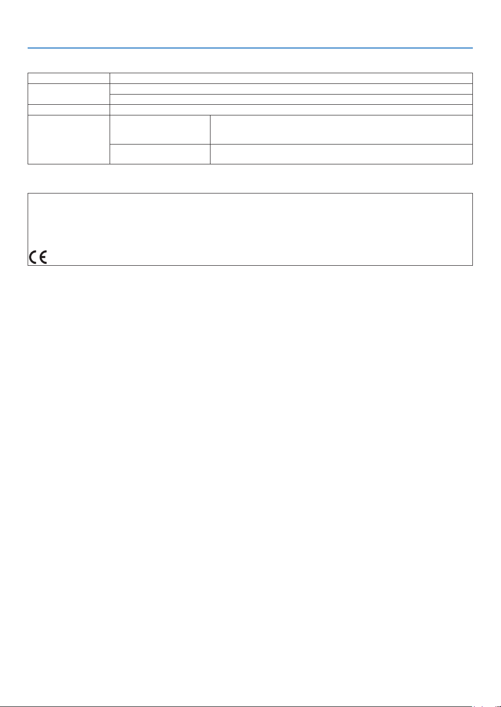
124
8. Appendix
Mechanical
Installation Orientation: Desktop/Front, Desktop/Rear, Ceiling/Front, Ceiling/Rear
Dimensions
12.2"(W) x 4.9"(H) x 11.4"(D) (not including protrusions)
310 mm (W) x 125 mm (H) x 289 mm (D) (not including protrusions)
Weight 8.2 lbs/3.7 kg
Environmental
Considerations
Operational Temperatures :
41° to 104°F / 5° to 40°C,
(Eco mode selected automatically at 95° to 104°F/35° to 40°C), 20% to
80% humidity (non-condensing)
Storage Temperatures :
14° to 122°F (-10° to 50°C), 20% to 80% humidity
(non-condensing)
Regulations
UL/C-UL Approved (UL 60950-1, CSA 60950-1)
Meets DOC Canada Class B requirements
Meets FCC Class B requirements
Meets AS/NZS CISPR.22 Class B
Meets EMC Di rect ive (EN55022, EN55024, EN61000-3-2, EN61000-3-3)
Meets Low Voltage Directive (EN60950-1, TÜV GS Approved)
For additional information visit:
US : http://www.necdisplay.com/
Europe : http://www.nec-display-solutions.com/
Global : http://www.nec-pj.com/
For information on our optional accessories, visit our website or see our brochure.
The speci cations are subject to change without notice.
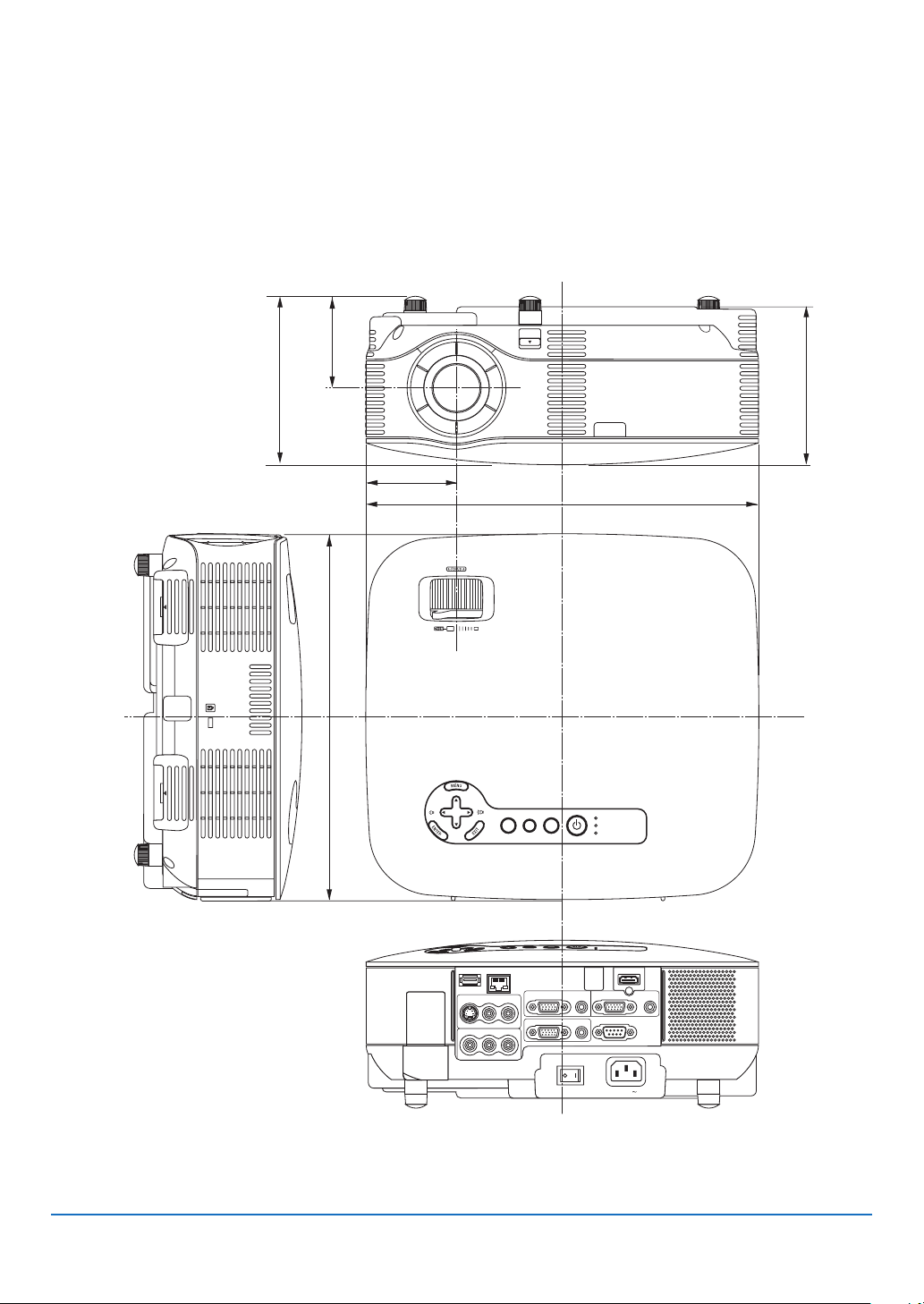
125
8. Appendix
❸
Cabinet Dimensions
WIRELESS
WIRELESS
USB
LAMP
STATUS
SOURCE
AUTO ADJUST
3D REFORM
SELECT
VIDEO IN
AUDIO IN
USB
LAN
AUDIO IN
HDMI IN
AUDIO IN
COMPUTER /
COMPONENT 2 IN
COMPUTER /
COMPONENT 1 IN
PC CONTROL
MONITOR OUT
AUDIO OUT
S-VIDEO IN
AUDIO IN
L/MONO
L/MONO
R
R
AC IN
289 (11.4)
125 (4.9)
310 (12.2)
71.4 (2.8)
72.3 (2.8)
133 (5.2)
Unit: mm (inch)
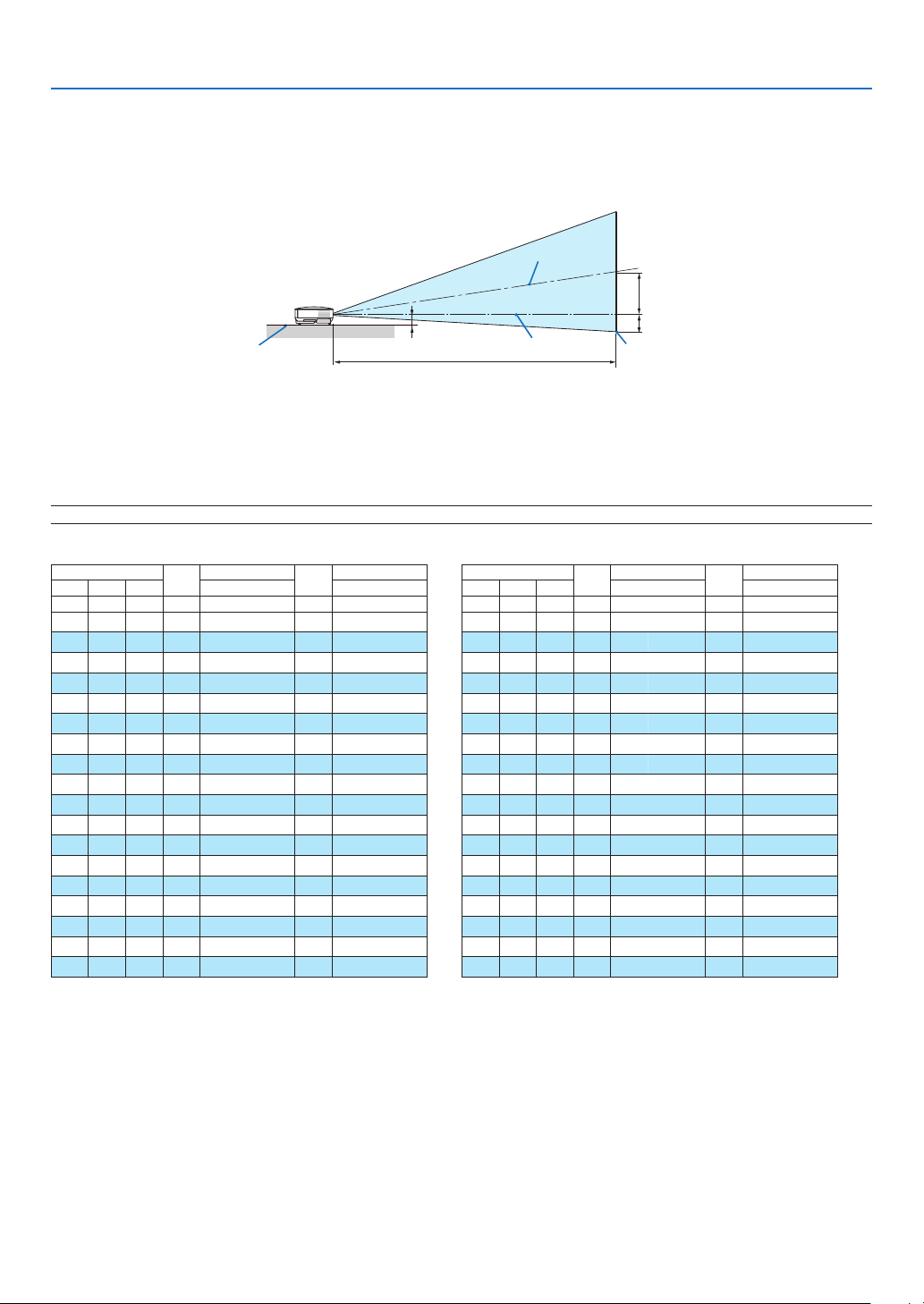
126
8. Appendix
❹
Screen Size and Projection Distance
Throw Distance and Screen Size
The following shows the proper relative positions of the projector and screen. Refer to the table to determine the
position of installation.
D
B
C
Projector bottom
2.85"/72.3 mm
Lens center Screen bottom
Screen center
Distance Chart
B = Vertical distance between lens center and screen center
C = Throw distance
D = Vertical distance between lens center and screen bottom (top of screen for ceiling application)
α = Throw angle
NOTE: The values in the tables are design values and may vary.
Screen Size
B
C
D
a
Diagonal Width Height Wide – Tele Wide – Tele
inch inch inch inch inch inch degree
21 17 13 4 – – 29 -2 – – 8.6
25 20 15 5 28 – 34 -2 10.3 – 8.6
30 24 18 6 34 – 41 -3 10.2 – 8.5
40 32 24 8 46 – 56 -4 10.1 – 8.4
60 48 36 12 70 – 84 -6 10.1 – 8.4
72 58 43 15 84 – 101 -7 10.0 – 8.4
80 64 48 17 93 – 112 -8 10.0 – 8.4
84 67 50 17 98 – 118 -8 10.0 – 8.4
90 72 54 19 105 – 126 -8 10.0 – 8.4
100 80 60 21 117 – 141 -9 10.0 – 8.3
120 96 72 25 141 – 169 -11 10.0 – 8.3
150 120 90 31 176 – 211 -14 10.0 – 8.3
180 144 108 37 211 – 254 -17 10.0 – 8.3
200 160 120 41 235 – 282 -19 10.0 – 8.3
210 168 126 43 247 – 296 -20 10.0 – 8.3
240 192 144 50 282 – 339 -23 9.9 – 8.3
270 216 162 56 318 – 381 -25 9.9 – 8.3
300 240 180 62 353 – 424 -28 9.9 – 8.3
Screen Size
B
C
D
a
Diagonal Width Height Wide – Tele Wide – Tele
mm mm mm mm mm mm degree
533 427 320 110 –– 730 -50 –– 8.6
635 508 381 130 720 – 870 -60 10.3 – 8.6
762 610 457 160 870 – 1050 -70 10.2 – 8.5
1016 813 610 210 1170 – 1410 -100 10.1 – 8.4
1524 1219 914 310 1770 – 2130 -140 10.1 – 8.4
1829 1463 1097 380 2130 – 2560 -170 10.0 – 8.4
2032 1626 1219 420 2370 – 2850 -190 10.0 – 8.4
2134 1707 1280 440 2490 – 2990 -200 10.0 – 8.4
2286 1829 1372 470 2670 – 3210 -210 10.0 – 8.4
2540 2032 1524 520 2970 – 3570 -240 10.0 – 8.3
3048 2438 1829 630 3570 – 4290 -290 10.0 – 8.3
3810 3048 2286 790 4470 – 5370 -360 10.0 – 8.3
4572 3658 2743 940 5370 – 6450 -430 10.0 – 8.3
5080 4064 3048 1050 5970 – 7170 -480 10.0 – 8.3
5334 4267 3200 1100 6270 – 7530 -500 10.0 – 8.3
6096 4877 3658 1260 7170 – 8610 -570 9.9 – 8.3
6858 5486 4115 1410 8070 – 9690 -640 9.9 – 8.3
7620 6096 4572 1570 8970 – 10770 -710 9.9 – 8.3
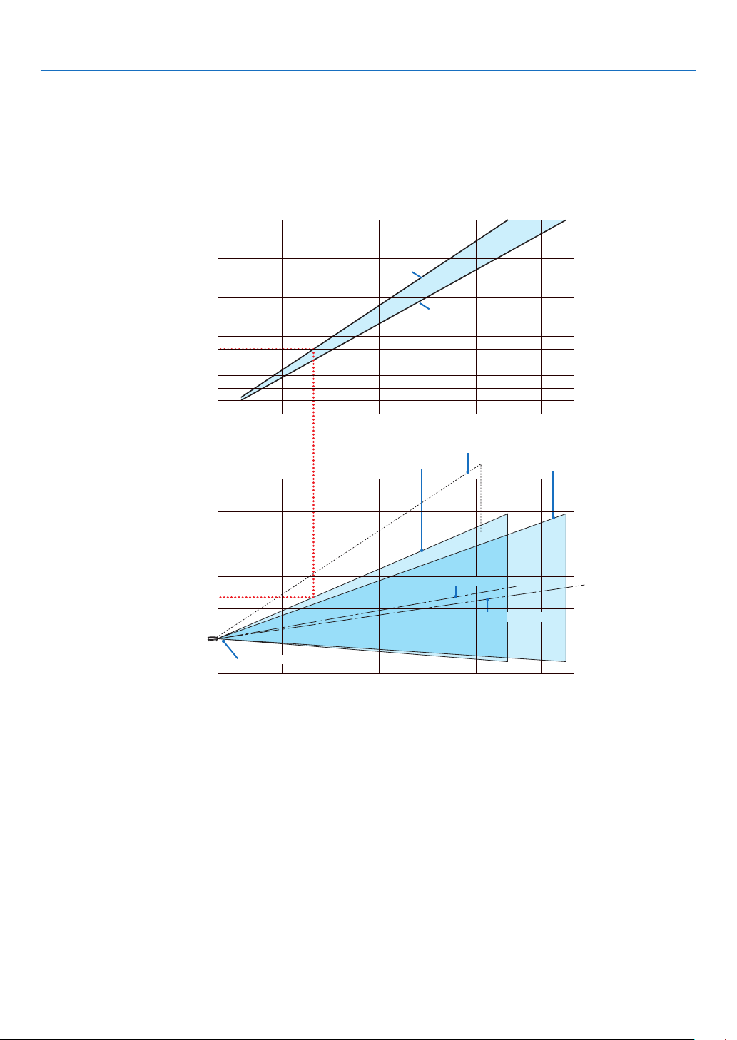
127
8. Appendix
This section should be used when considering the distance to the screen and the screen size.
Available projection distances are 0.73 m/29 inches for 21" screen to 10.8 m/424 inches for 300" screen, accord-
ing to the chart.
Using the Chart
Example for 100" screen:
The projection distance is approximately 3.0 m (120") according to the upper chart.
The lower chart shows that the vertical distance between the projector foot and the screen top is approximately 1.35
m (53"). The projection angle can be adjusted up to 10°. (The lower chart shows that the projector is placed in a
horizontal position)
Throw distance
21
01234567891011(m)
0
1
-1
2
3
4
5
12345678910
11(m)
(m)
40
30
60
80
100
120
150
180
200
240
300
Vertical distance
between projector
foot and screen top
Screen size
(Diagonal)
(Model)
When tilted at an angle 10 in Wide
Tele
Tele
Wide
Screen center line (Wide)
Projector foot
Screen center line (Tele)
Wide

128
8. Appendix
Mini D-Sub 15 Pin Connector
❺
Pin Assignments of D-Sub COMPUTER1/2 Input Connector
Signal Level
Video signal : 0.7Vp-p (Analog)
Sync signal : TTL level
1115 1214 13
6
54321
10 798
Pin No. RGB Signal (Analog) YCbCr Signal
1 Red Cr
2 Green or Sync on Green Y
3 Blue Cb
4 Ground
5 Ground
6 Red Ground Cr Ground
7 Green Ground Y Ground
8 Blue Ground Cb Ground
9 No Connection
10 Sync Signal Ground
11 No Connection
12 Bi-directional DATA (SDA)
13 Horizontal Sync or Composite Sync
14 Vertical Sync
15 Data Clock

129
8. Appendix
❻
Compatible Input Signal List
Signal Resolution
(Dots)
Frequency H.
(kHz)
Refresh Rate
(Hz)
NTSC/PAL60 * 15.73 59.94
PAL * 15.63 50.00
PAL60 * 15.73 60.00
SECAM * 15.63 50.00
VESA 640 × 480 31.47 59.94
MAC 13" 640 × 480 35.00 66.67
VESA 640 × 480 37.86 72.81
VESA 640 × 480 37.50 75.00
IBM 640 × 480 39.38 75.00
VESA 640 × 480 43.27 85.01
VESA 800 × 600 35.16 56.25
VESA 800 × 600 37.88 60.32
VESA 800 × 600 48.01 72.19
VESA 800 × 600 46.88 75.00
VESA 800 × 600 53.67 85.06
MAC 16" 832 × 624 49.72 74.55
VESA 1024 × 768 48.36 60.00
VESA 1024 × 768 56.48 70.07
MAC 19" 1024 × 768 60.24 74.93
VESA 1024 × 768 60.02 75.03
VESA 1024 × 768 68.68 85.00
VESA 1152 × 864 54.35 60.05
VESA 1152 × 864 63.99 70.02
VESA 1152 × 864 67.50 75.00
VESA 1152 × 864 77.49 85.06
MAC 21" 1152 × 870 68.68 75.06
SUN 1152 × 900 61.80 65.95
SGI 1152 × 900 71.74 76.05
VESA 1280 × 768 47.78 59.87
VESA 1280 × 768 60.29 74.89
VESA 1280 × 768 68.63 84.84
VESA 1280 × 800 49.70 59.81
VESA 1280 × 800 62.80 74.93
VESA 1280 × 800 71.55 84.88
VESA 1280 × 960 60.00 60.00
VESA 1280 × 960* 75.00 75.00
VESA 1280 × 960* 85.94 85.00
VESA 1280 × 1024 63.98 60.02
MAC 23" 1280 × 1024 69.87 65.18
VESA 1280 × 1024* 79.98 75.02
VESA 1280 × 1024* 91.15 85.02
VESA 1400 × 1050 65.32 60.00
VESA 1400 × 1050* 82.28 74.87
VESA 1440 × 900 55.94 59.89
VESA 1440 × 900* 70.64 74.98
VESA 1440 × 900* 80.43 84.84
VESA 1600 × 1200* 75.00 60.00
VESA 1600 × 1200* 81.25 65.00
VESA 1600 × 1200* 87.50 70.00
VESA 1600 × 1200* 93.75 75.00
VESA 1680 × 1050* 65.29 59.95
HDTV (1080p /60) 1920 × 1080 67.50 60.00 Progressive
HDTV (1080p /50) 1920 × 1080 56.25 50.00 Progressive
HDTV (1080i /60) 1920 × 1080 33.75 60.00 interlace
HDTV (1080i /50) 1920 × 1080 28.13 50.00 interlace
HDTV (750p) 1280 × 720 45.00 60.00 Progressive
SDTV (480p) 720 × 480 31.47 59.94 Progressive
SDTV (576p) 720 × 576 31.25 50.00 Progressive
DVD YCbCr 720 × 480* 15.73 59.94 interlace
DVD YCbCr 720 × 576* 15.63 50.00 interlace
DVD Progressive 720 × 480 31.47 59.94 Progressive
DVD Progressive 720 × 576 31.25 50.00 Progressive
* Images above agged with "*" are not supported by digital signal.
NOTE:
• An image with higher or lower resolution than the
projector’s native resolution (1024 x 768) will be dis-
played with scaling technology.
• Some composite sync signals may not be displayed
correctly.
Signals other than those specifi ed in the table above
may not be displayed correctly. If this should hap-
pen, change the refresh rate or resolution on your
PC. Refer to Display Properties help section of your
PC for procedures.

130
8. Appendix
❼
PC Control Codes and Cable Connection
PC Control Codes
Function Code Data
POWER ON 02H 00H 00H 00H 00H 02H
POWER OFF 02H 01H 00H 00H 00H 03H
INPUT SELECT COMPUTER1 02H 03H 00H 00H 02H 01H 01H 09H
INPUT SELECT COMPUTER2 02H 03H 00H 00H 02H 01H 02H 0AH
INPUT SELECT HDMI 02H 03H 00H 00H 02H 01H 1AH 22H
INPUT SELECT VIDEO 02H 03H 00H 00H 02H 01H 06H 0EH
INPUT SELECT S-VIDEO 02H 03H 00H 00H 02H 01H 0BH 13H
INPUT SELECT VIEWER 02H 03H 00H 00H 02H 01H 1FH 27H
PICTURE MUTE ON 02H 10H 00H 00H 00H 12H
PICTURE MUTE OFF 02H 11H 00H 00H 00H 13H
SOUND MUTE ON 02H 12H 00H 00H 00H 14H
SOUND MUTE OFF 02H 13H 00H 00H 00H 15H
ON SCREEN MUTE ON 02H 14H 00H 00H 00H 16H
ON SCREEN MUTE OFF 02H 15H 00H 00H 00H 17H
ASPECT RATIO (4:3 Screen)
4:3 03H 10H 00H 00H 05H 18H 00H 00H 00H 00H 30H
LETTERBOX 03H 10H 00H 00H 05H 18H 00H 00H 01H 00H 31H
WIDESCREEN 03H 10H 00H 00H 05H 18H 00H 00H 02H 00H 32H
ZOOM 03H 10H 00H 00H 05H 18H 00H 00H 03H 00H 33H
ASPECT RATIO (16:9 Screen)
4:3 WINDOW 03H 10H 00H 00H 05H 18H 00H 00H 00H 00H 30H
LETTERBOX 03H 10H 00H 00H 05H 18H 00H 00H 01H 00H 31H
WIDESCREEN 03H 10H 00H 00H 05H 18H 00H 00H 02H 00H 32H
4:3 FILL 03H 10H 00H 00H 05H 18H 00H 00H 04H 00H 34H
ASPECT RATIO (RGB)
4:3 03H 10H 00H 00H 05H 18H 00H 00H 00H 00H 30H
16:9 03H 10H 00H 00H 05H 18H 00H 00H 02H 00H 32H
5:4 03H 10H 00H 00H 05H 18H 00H 00H 0BH 00H 3BH
16:10 03H 10H 00H 00H 05H 18H 00H 00H 0CH 00H 3CH
15:9 03H 10H 00H 00H 05H 18H 00H 00H 0DH 00H 3DH
AUTO ADJUST 02H 0FH 00H 00H 02H 05H 00H 18H
NOTE: Contact your local dealer for a full list of PC Control Codes if needed.
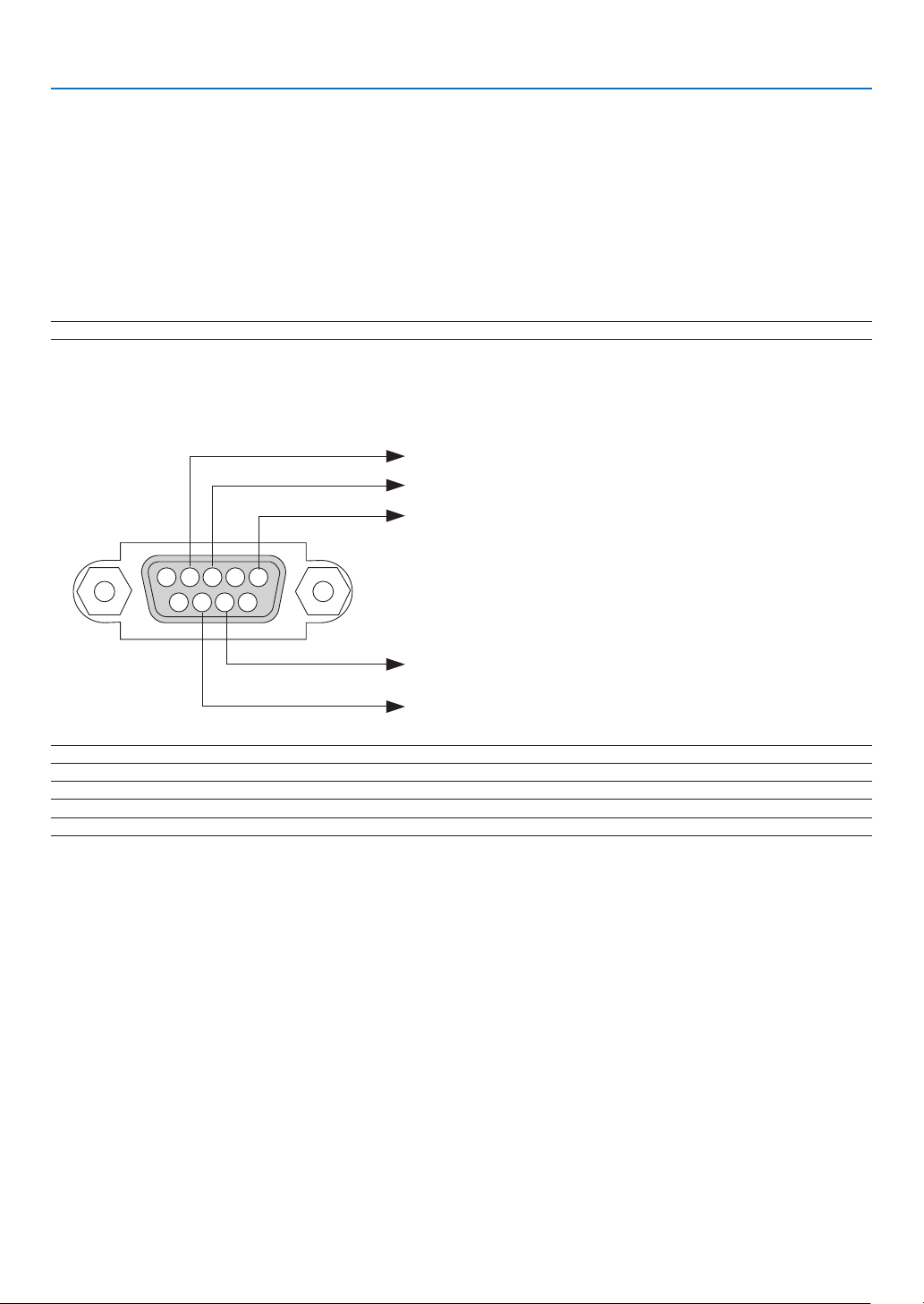
131
8. Appendix
NOTE 1: Pins 1, 4, 6 and 9 are not used.
NOTE 2: Jumper “Request to Send” and “Clear to Send” together on both ends of the cable to simplify cable connection.
NOTE 3: For long cable runs it is recommended to set communication speed within projector menus to 9600 bps.
15243
67 98
To GND of PC
To RxD of PC
To TxD of PC
To RTS of PC
To CTS of PC
PC Control Connector (D-SUB 9P)
Cable Connection
Communication Protocol
Baud rate ......................................... 38400 bps
Data length ...................................... 8 bits
Parity ............................................... No parity
Stop bit ............................................ One bit
X on/off ............................................ None
Communications procedure ............ Full duplex
NOTE: Depending on the equipment, a lower baud rate may be recommended for long cable runs.

132
8. Appendix
No image is displayed from your PC or video equipment to the
projector.
Still no image even though you connect the projector to the
PC fi rst, then start the PC.
Enabling your notebook PC’s signal output to the projector.
• A combination of function keys will enable/disable the
external display. Usually, the combination of the “Fn” key
along with one of the 12 function keys turns the external
display on or off.
No image (blue background, logo, no display).
Still no image even though you press the AUTO ADJUST
button.
Still no image even though you carry out [RESET] in the
projector’s menu.
Signal cable’s plug is fully inserted into the input connector
A message appears on the screen.
()
The source connected to the projector is active and available.
Still no image even though you adjust the brightness and/
or the contrast.
Input source’s resolution and frequency are supported by
the projector.
❽
Troubleshooting Check List
Before contacting your dealer or service personnel, check the following list to be sure repairs are needed also by
referring to the “Troubleshooting” section in your user’s manual. This checklist below will help us solve your prob-
lem more ef ciently.
* Print the following pages.
Frequency of occurrence □ always □ sometimes (How often? ) □ other ( )
Power
No power (POWER indicator does not light green) See also
“Status Indicator (STATUS)”.
Power cable’s plug is fully inserted into the wall outlet.
Main power switch is pressed to the ON position.
Lamp cover is installed correctly .
Lamp Hours Used (lamp operation hours) was cleared after
lamp replacement.
No power even though you press and hold the POWER but-
ton for a minimum of 2 seconds.
Shut down during operation.
Power cable’s plug is fully inserted into the wall outlet.
Lamp cover is installed correctly .
[AUTO POWER OFF] is turned off (only models with the
[AUTO POWER OFF] function).
[OFF TIMER] is turned off (only models with the [OFF
TIMER] function ).
[PROGRAM TIMER] is turned off (only models with the
[PROGRAM TIMER] function.)
Video and Audio
Image is too dark.
Remains unchanged even though you adjust the brightness
and/or the contrast.
Image is distorted.
Image appears to be trapezoidal (unchanged even though
you carry out the [KEYSTONE] adjustment).
Parts of the image are lost.
Still unchanged even though you press the AUTO ADJUST
button.
Still unchanged even though you carry out [RESET] in the
projector’s menu.
Image is shifted in the vertical or horizontal direction.
Horizontal and vertical positions are correctly adjusted on
a computer signal.
Input source’s resolution and frequency are supported by
the projector.
Some pixels are lost.
Image is fl ickering.
Still unchanged even though you press the AUTO ADJUST
button.
Still unchanged even though you carry out [RESET] in the
projector’s menu.
Image shows fl ickering or color drift on a computer signal.
Still unchanged even though you change [FAN MODE] from
[HIGH ALTITUDE] to [AUTO].
Image appears blurry or out of focus.
Still unchanged even though you checked the signal’s resolu-
tion on PC and changed it to projector’s native resolution.
Still unchanged even though you adjusted the focus.
No sound.
Audio cable is correctly connected to the audio input of the
projector.
Still unchanged even though you adjusted the volume level.
AUDIO OUT is connected to your audio equipment (only
models with the AUDIO OUT connector).
Other
Remote control does not work.
No obstacles between the sensor of the projector and the
remote control.
Projector is placed near a fl uorescent light that can disturb
the infrared remote controls.
Batteries are new and are not reversed in installation.
If present on the remote control, projector selector switch
is not used.
Buttons on the projector cabinet do not work ( only models
with the
[CONTROL PANEL LOCK]
function).
[CONTROL PANEL LOCK] is not turned on or is disabled in the
menu.
Still unchanged even though you press and hold the EXIT
button for a minimum of 10 seconds.
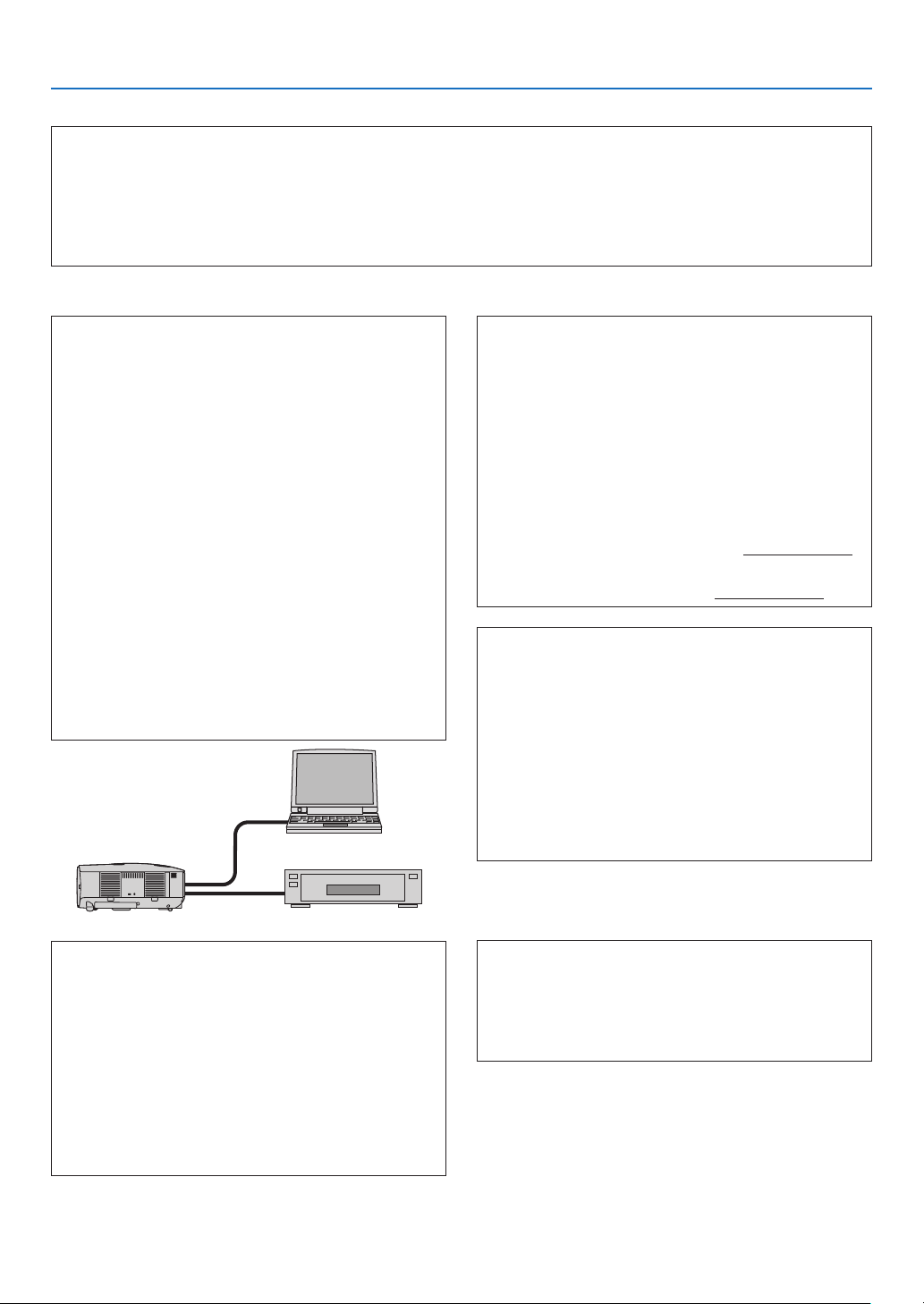
133
8. Appendix
In the space below please describe your problem in detail.
Information on application and environment where your projector is used
Projector
Model number:
Serial No.:
Date of purchase:
Lamp operating time (hours):
Lamp Mode: □ Normal □ Eco
Information on input signal:
Horizontal synch frequency [ ] kHz
Vertical synch frequency [ ] Hz
Synch polarity H □ (+) □ (–)
V □ (+) □ (–)
Synch type □ Separate □ Composite
□ Sync on Green
STATUS Indicator:
Steady light □ Orange □ Green
Flashing light [ ] cycles
Remote control model number:
Signal cable
NEC standard or other manufacturer’s cable?
Model number: Length: inch/m
Distribution amplifi er
Model number:
Switcher
Model number:
Adapter
Model number:
Projector
PC
DVD player
Installation environment
Screen size: inch
Screen type: □ White matte □ Beads □ Polarization
□ Wide angle □ High contrast
Throw distance: feet/inch/m
Orientation: □ Ceiling mount □ Desktop
Power outlet connection:
□ Connected directly to wall outlet
□ Connected to power cord extender or other (the
number of connected equipment
)
□ Connected to a power cord reel or other (the num-
ber of connected equipment )
Computer
Manufacturer:
Model number:
Notebook PC □ / Desktop □
Native resolution:
Refresh rate:
Video adapter:
Other:
Video equipment
VCR, DVD player, Video camera, Video game or other
Manufacturer:
Model number:

134
8. Appendix
쐎
TravelCare Guide
TravelCare - a service for international travelers
This product is eligible for “TravelCare”, NEC’s unique international
warranty.
Please note that TravelCare coverage differs in part from coverage
under the warranty included with the product.
Services offered with TravelCare
This warranty allows customers to receive service on their product at
the NEC and NEC-designated service stations in the countries listed
herein when temporarily traveling internationally for business or plea-
sure.
For details on services offered by the different service stations, please
refer to the “List of TravelCare Outlets” below.
1 Repair services
The product will be repaired and delivered within 10 business days,
not including shipping time.
During the term of warranty, the cost of maintenance parts, labor
costs for repairs and shipping costs within the service station’s cov-
erage area are covered by the warranty.
2 Replacement product rental service
If the customer desires, he or she can rent a replacement product
while the original product is being repaired.
Fee: US$200 for 12 days
This fee must be paid at the local service station in cash or credit
card.
The US$200 rental fee is non-refundable even if the customer rents
it less than 12 days before returning.
The replacement product will be delivered within 3 business days.
If the customer did not return the replacement product within 12
days, the customer will be charged the price of the unit.
If the customer returned the replacement product in a faulty or
damaged condition, the repair cost will be charged to the customer.
Note that this service is not offered in all countries and regions.
Please refer to the “List of TravelCare Outlets”.
In addition, this replacement product rental service is not offered
after the product’s warranty has expired.
Term of warranty
1
a. Upon presentation of the warranty or receipt received upon
purchase:
Valid for the term indicated on the warranty or the normal term
of warranty for the country of purchase.
b. When only the product is brought in:
Valid for a period of within 14 months of the date of manufac-
ture indicated by the serial number attached to the product.
2 When a product whose term of warranty is expired is brought in:
Repairs will be offered for a fee. In this case the customer is not
eligible for the replacement product rental service.
3 In the following cases, repairs may be charged, even if the product’
s warranty is still in effect:
1) If the term of warranty, model name, serial number and name
of the store of purchase are not indicated on the warranty or
have been altered.
2) Problems or damage caused by dropping or shocks during
shipment or movement by the customer or by improper han-
dling by the customers.
3) Problems or damage caused by improper usage or unwarrant-
able alterations or repairs by the customer.
4) Problems or damage caused by fi re, salt damage, gas dam-
age, earthquakes, lightning damage, storm or fl ood damage or
other natural disasters or such external factors as dust, ciga-
rette smoke, abnormal voltage, etc.
5) Problems or damage caused by use in hot or humid places, in
vehicles, boats or ships, etc.
6) Problems or damage caused by expendable supplies or de-
vices connected to the product other than those designated by
NEC.
7) Problems caused by natural consumption, wear or deteriora-
tion of parts under normal usage conditions.
8) Problems or damage to lamps and other expendable supplies,
included parts or optional parts.
9) Other conditions stipulated in the warranty included with the
product also apply.
NOTE: The product can be used overseas with voltages of 100 to 120V and
200 to 240V by using a power cable suited for the standards and power source
voltage of the country in which the product is being used.
List of TravelCare Outlets
This list applies as of July 1, 2008.
For the most up-to-date information, please refer to the websites of
the service stations in the various countries on the List of TravelCare
Outlets or to the NEC website at http://www.nec-pj.com.
In Europe
NEC Europe, Ltd. / European Technical Centre
Address: Unit G, Stafford Park 12, Telford TF3 3BJ, U.K.
Telephone: +44 1952 237000
Fax Line: +44 1952 237006
Email Address: [email protected]
WEB Address: http://www.neceur.com
(Regions Covered)
EU:
Austria*, Belgium*, Denmark*, Finland*, France*, Germany*,
Greece*, Ireland*, Italy*, Luxembourg*, The Netherlands*,
Portugal*, Spain*, Sweden* and the United Kingdom*
EEA: Norway*, Iceland and Liechtenstein
In North America
NEC Display Solutions of America, Inc.
Address: 500 Park Boulevard, Suite 1100
Itasca, Illinois 60143, U.S.A.
Telephone: +1 800 836 0655
Fax Line: +1 800 356 2415
Email Address: [email protected]
WEB Address: http://www.necdisplay.com/
(Regions Covered)
U.S.A. *, Canada*
In Oceania
NEC Australia Pty., Ltd.
Address:
New South Wales;
Sydney
184 Milperra Road, Reversby NSW 2212
Telephone: 131 632
Newcastle
120 Parry Street Newcastle West NSW 2302
Telephone: 131 632
Victoria;
Melbourne
Unit 1/6 Garden Road, Clayton VIC 3168
Telephone: 131 632
Queensland;
Brisbane
Unit 4/305 Montague Road West End QLD 4101
Telephone: 131 632
Southport
Shop1 48 Ferry Road Southport QLD 4215
Telephone: 131 632
South Australia;
Adelaide
84A Richmond Road, Keswick SA 5035
Telephone: 131 632
Western Australia;
Perth
45 Sarich Court Osborne Park WA 6017
Telephone: 131 632
WEB Address:
http://www.nec.com.au
(Regions Covered)
Australia*, New Zealand

135
8. Appendix
Hyosung ITX Co., Ltd.
Address: 1st Fl., Ire B/D. #2, 4Ga, Yangpyeng-Dong,
Youngdeungpo-Gu, Seoul, Korea 150-967
Telephone: +82 2 2163 4193
Fax Line: +82 2 2163 4196
Email Address: [email protected]
(Regions Covered)
South Korea
Lenso Communication Co., Ltd.
Address:
292 Lenso House 4, 1st Floor, Srinakarin Road,
Huamark, Bangkapi, Bangkok 10240, Thailand
Telephone: +66 2 375 2425
Fax Line: +66 2 375 2434
Email Address: [email protected]
WEB Address: http://www.lensocom.com/
(Regions Covered)
Thailand
ABBA Electronics L.L.C.
Address: Tariq Bin Ziyad Road, P.O.Box 327, Dubai,
United Arab Emirates
Telephone: +971 4 371800
Fax Line: +971 4 364283
Email Address: [email protected]
(Regions Covered)
United Arab Emirates
Samir Photographic Supplies
Address: P.O.Box 599, Jeddah 21421, Saudi Arabia
Telephone: +966 2 6828219
Fax Line: +966 2 6830820
Email Address: [email protected]
Riyadh
Address: P.O.Box 5519, Riyadh 11432, Saudi Arabia
Telephone: +966 1 4645064
Fax Line: +966 1 4657912
Email Address: [email protected]
Alkhobar
Address: P.O.Box 238, Alkhobar 31952, Saudi Arabia
Telephone: +966 3 8942674
Fax Line: +966 3 8948162
Email Address: [email protected]
(Regions Covered)
Saudi Arabia
NOTE: In countries designated with an asterisk(*), replacement product rental
service are offered.
In Asia and Middle East
NEC Display Solutions, Ltd.
Address: 686-1, Nishioi, Oi-Machi, Ashigarakami-Gun,
Kanagawa 258-0017, Japan
Telephone: +81 465 85 2369
Fax Line: +81 465 85 2393
Email Address: [email protected]
WEB Address:
http://www.nec-pj.com
(Regions Covered)
Japan*
NEC Solutions (China) Co.,Ltd.
Address: Rm 1903, Shining Building, 35 Xueyuan Rd,
Haidian District Beijing 100083, P.R.C.
Telephone: +8610 82317788
Fax Line: +8610 82331722
Email Address: [email protected]
WEB Address: http://www.necsl.com.cn
(Regions Covered)
China
NEC Hong Kong Ltd.
Address:
25/F.,The Metropolis Tower, 10 Metropolis
Drive,
Hunghom, Kowloon, Hong Kong
Telephone: +852 2369 0335
Fax Line: +852 2795 6618
Email Address: [email protected]
WEB Address: http://www.nec.com.hk
(Regions Covered)
Hong Kong
NEC Taiwan Ltd.
Address:
7F, No.167, SEC.2, Nan King East Road, Tai-
pei,
Taiwan, R.O.C.
Telephone: +886 2 8500 1700
Fax Line: +886 2 8500 1420
Email Address: [email protected]
WEB Address: http://www.nec.com.tw
(Regions Covered)
Taiwan
NEC Asia Pte.Ltd.
Address: 401 Commonwealth Drive, #07-02, Haw Par
Technocentre, Singapore 149598
Telephone: +65 6 273 8333
Fax Line: +65 6 274 2226
Email Address: [email protected]
WEB Address: http://www.nec.com.sg/ap
(Regions Covered)
Singapore
NEC Corporation of Malaysia Sdn. Bhd.
Address:
33rd Floor, Menara TA One, 22, Jalan P. Ramlee,
50250 Kuala Lumpur, Malaysia
Telephone: +6 03 2178 3600 (ISDN)
Fax Line: +6 03 2178 3789
Email Address: [email protected]
WEB Address: http://www.necarecenter.com
(Regions Covered)
Malaysia

136
8. Appendix
TO: NEC or NEC’s Authorized Service Station:
FM:
(Company & Name with signature)
Dear Sir (s),
I would like to apply your TravelCare Service Program based on attached registration and quali cation sheet and agree with
your following conditions, and also the Service fee will be charged to my credit card account, if I don’t return the Loan units
within the speci ed period. I also con rm following information is correct. Regards.
Application Sheet for TravelCare Service Program
P-1/ ,
Country,
product purchased :
User’s Company Name :
User’s Company Address :
Phone No., Fax No. :
User’s Name :
User’s Address :
Phone No., Fax No. :
Local Contact of ce :
Local Contact of ce Address :
Phone No., Fax No. :
User’s Model Name :
Date of Purchase :
Serial No. on cabinet :
Problem of units per User :
Required Service : (1) Repair and Return (2) Loan unit
Requested period of Loan unit :
Payment method : (1) Credit Card (2) Travelers Cheque (3) Cash
In Case of Credit Card :
Card No. w/Valid Date :
Date: / / ,

137
8. Appendix
5. Loan Service Charges and Conditions:
Upon acceptance of this NEC Projector, Customer agrees to assume
liability for this loan unit.
The current cost of use of this loan unit is $200.00 USD for 12 calen-
dar days.
If Customer does not return the unit within the 12 calendar days, Cus-
tomer will be charged the next highest cost up to and including the full
list price to Credit Cards, which price will be informed by NEC Autho-
rized Service Stations. Please see the attached listing of contacts for
each country to arrange for pickup of the loan unit.
If you return to their country of origin with the loan unit, you will be
charged additional freight to return the unit to the loaning country.
Thank you for your understanding of this program.
Condition of your TravelCare Service Program
Enduser is requested to understand following condition of TravelCare
Service Program and complete the necessary information on the ap-
plication sheet.
1. Service Options:
There are 3 types of “Service” available. Enduser has to understand
following condition and is required to ll in the Application Sheet.
1) Repair and Return:
The ’Faulty unit’ is sent or collected from the customer. It is re-
paired and returned within 10 days to the customer, excluding
transport time.
There may have a case, repair and return can’t be done by NEC
Authorized Service Station, because of shortage of spare parts due
to same model is not sold in the territory.
2) Repair and Return with Loan: (This service is limited to some Ser-
vice Stations)
This service is offered to the Enduser, who cannot wait until their
unit is repaired.
The customer can borrow a unit for $200 up to 12 days. Customer
then sends in inoperable unit to nearest NEC Authorized Service
Station for service. In order to prevent collection problem, Enduser
is required to ll in Application Sheet.
Enduser needs to con rm the availability of the Service to NEC Au-
thorized Service Stations.
3) Loan Only:
For this service, NEC Authorized Service Station supplies the cus-
tomer with a loan unit for US$200 up to 12 days. Customer keeps
the inoperable unit and when customer returns home, customer
arranges to have the projector serviced in the home country.
2. Warranty Exclusions:
This program does not apply if the Projector’s serial number has been
defaced, modi ed or removed.
If, in the judgement of NEC Authorized Service Station or its agent the
defects or failures result from any cause other than fair wear and tear
or NEC neglect, or fault including the following without limitation:
1) Accidents, transportation, neglect, misuse, abuse, water, dust,
smoke or default of or by the Customer its employees or agents or
any third party;
2) Failure or uctuation of electrical power, electrical circuitry, air con-
ditioning, humidity control or other environmental conditions such
as use it in smoking area;
3) Any fault in the attachments or associated products or components
(whether or not supplied by NEC or its agents which do not form
part of the Product covered by this warranty);
4) Any act of God, re, ood, war, act of violence or any similar occur-
rence;
5) Any attempt by any person other than any person authorized by
NEC to adjust, modify, repair, install or service the product.
6) Any Cross-border charges such as, duty, insurance, tax etc.
3. Charges for Warranty Exclusions and Out of Warranty Case:
In case faulty unit is under warranty exclusions case or under Out of
Warranty period, NEC Authorized Service Station will Inform estima-
tion of actual service cost to the Enduser with reason.
4. Dead on Arrival (DOA):
Enduser must take this issue up with their original supplier in the
country of purchase.
NEC Authorized Service Station will repair the DOA unit as a War-
ranty repair, but will not exchange DOA unit with new units.

© NEC Display Solutions, Ltd. 2008 7N951192