Ed :
Rev: Cod :
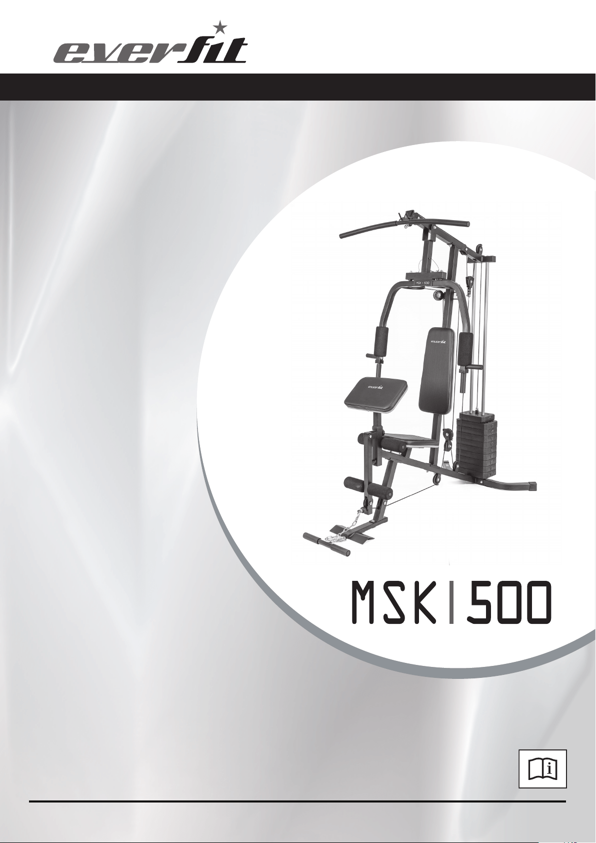
INSTRUCTION
08/18 GRLDEVEFTK500
00
3
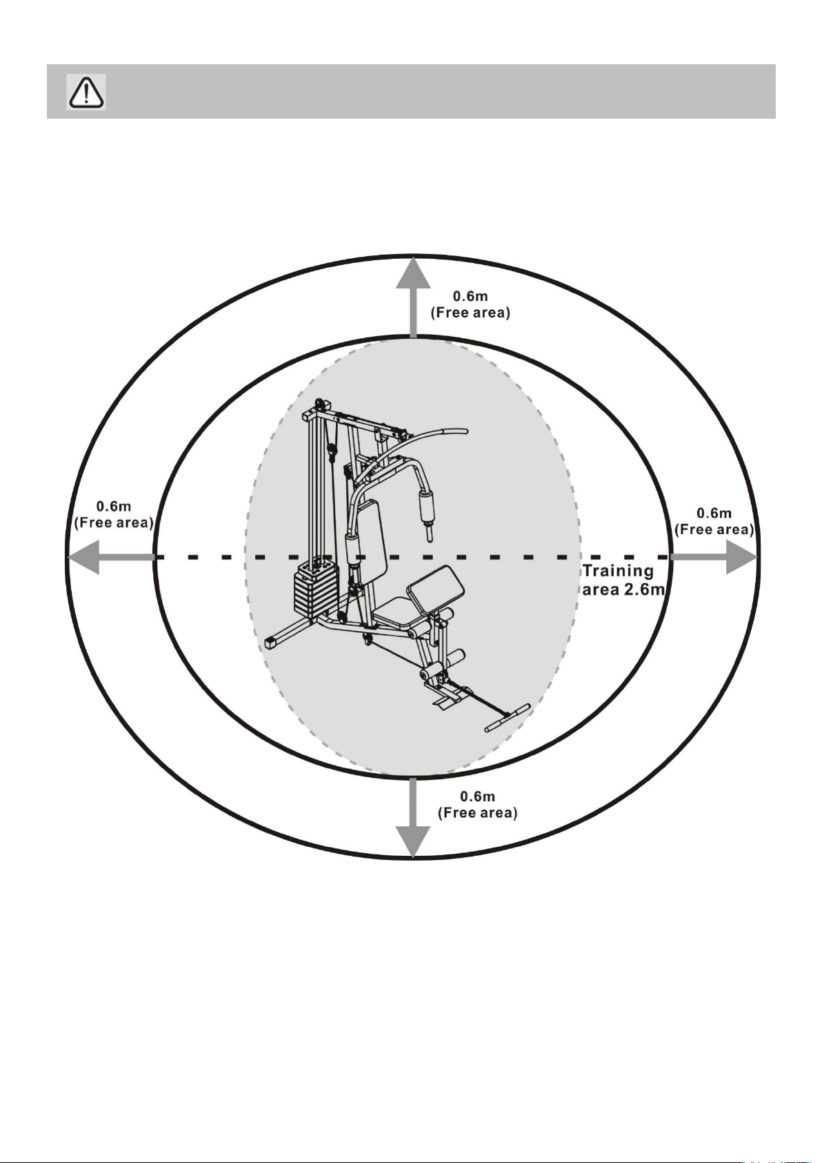
• Free area shall be not less than 0.6m greater than the training area in the directions from which
the equipment is accessed. The free area must also include the area for emergency dismount.
Where equipment is positioned adjacent to each other the value of the free area may be shared.
Keep unsupervised children away from the equipment.
Safety Information

MUST read all instructions before using any fitness equipment. Argos assumes no responsibility for
personal injury or property damage sustained by or through the use of this product.
Note: Some of the smaller components may be pre-fitted to larger components. Please check carefully
before contacting us regarding any missing components.
Components - Parts
4
Please check you have all parts listed below
1. Base frame × 1
2. Upper frame × 1
4. Rear stabilizer × 1
5. Leg developer holder × 1
3. Vertical frame × 1
6. Front press base × 1
7. Right butterfly × 1
8. Left butterfly × 1
9. Preacher pad
support × 1
10. Floating pulley
bracket × 1
11. Angle double
pulley bracket × 1
12. Swivel pulley
bracket × 2
13. Select rod × 1
14. Lat bar × 1
15. Leg developer × 1
16. Front stabilizer × 1
Note: Some of the smaller components may be pre-fitted to larger components. Please check carefully
before contacting us regarding any missing components.
Components - Parts
5
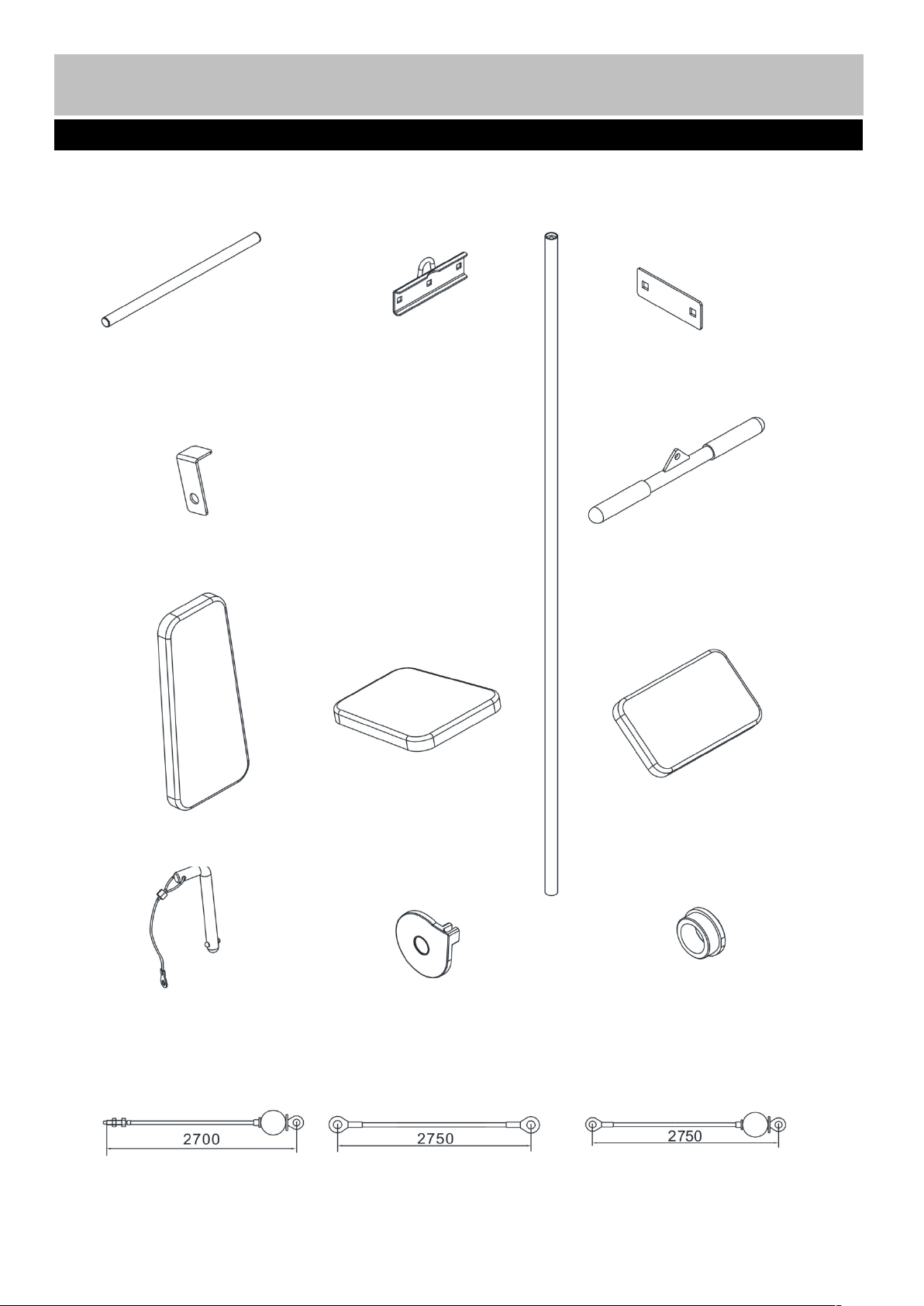
Please check you have all parts listed below
17. Foam roll tube × 2
19. Rear U-shaped
bracket × 1
20. 120mm Bracket × 3
22. L-shaped separation
blade × 2
18. Guide rod × 2
→
23. Pull bar × 1
24. Backrest pad × 1
25. Seat pad × 1
26. Preacher pad × 1
43. Seated press lock
pin × 2
46. Pulley cover × 6
48. Ø25mm × 31mm
Bushing × 2
49. 2700mm Upper
cable × 1
50. 2750mm Butterfly
cable × 1
51. 2750mm Lower
cable × 1
Note: Some of the smaller components may be pre-fitted to larger components. Please check carefully
before contacting us regarding any missing components.
Components - Parts
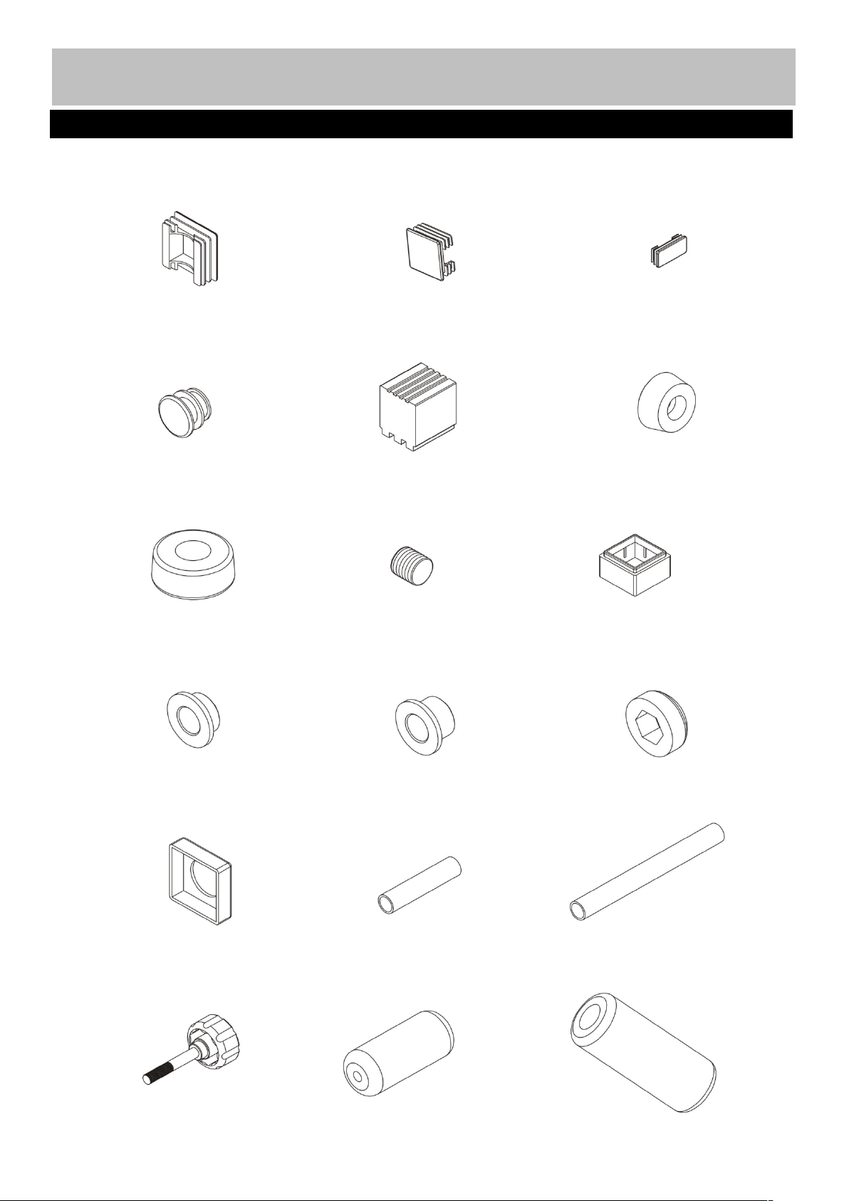
Please check you have all parts listed below
52. 45mm End cap × 5
53. 38mm End cap × 4
54. 25× 50mm
End cap × 4
55. Ø19mm End
cap× 4
56. Rear stabilizer end
cap × 2
57. Ø37mm
Rubber bumper × 1
58. Ø61mm Rubber
bumper × 2
59. 30mm Rubber
bumper × 1
60. 45mm ×38mm
Sleeve × 1
62. Ø22 × 11mm
Pulley bushing × 2
63. Ø22 × 15mm
Pulley bushing × 6
65. Ø26mm × 38mm
Hollow sleeve × 2
64. M10 Nut cap × 1
67. Lat pull handle grip × 2
68. Lock knob × 1
69. Ø17mm Foam
roll × 4
70. Ø45mm Foam roll × 2
66. Front press handle
Grip Ø25×130 × 4
6
Note: Some of the smaller components may be pre-fitted to larger components. Please check carefully
before contacting us regarding any missing components.
7
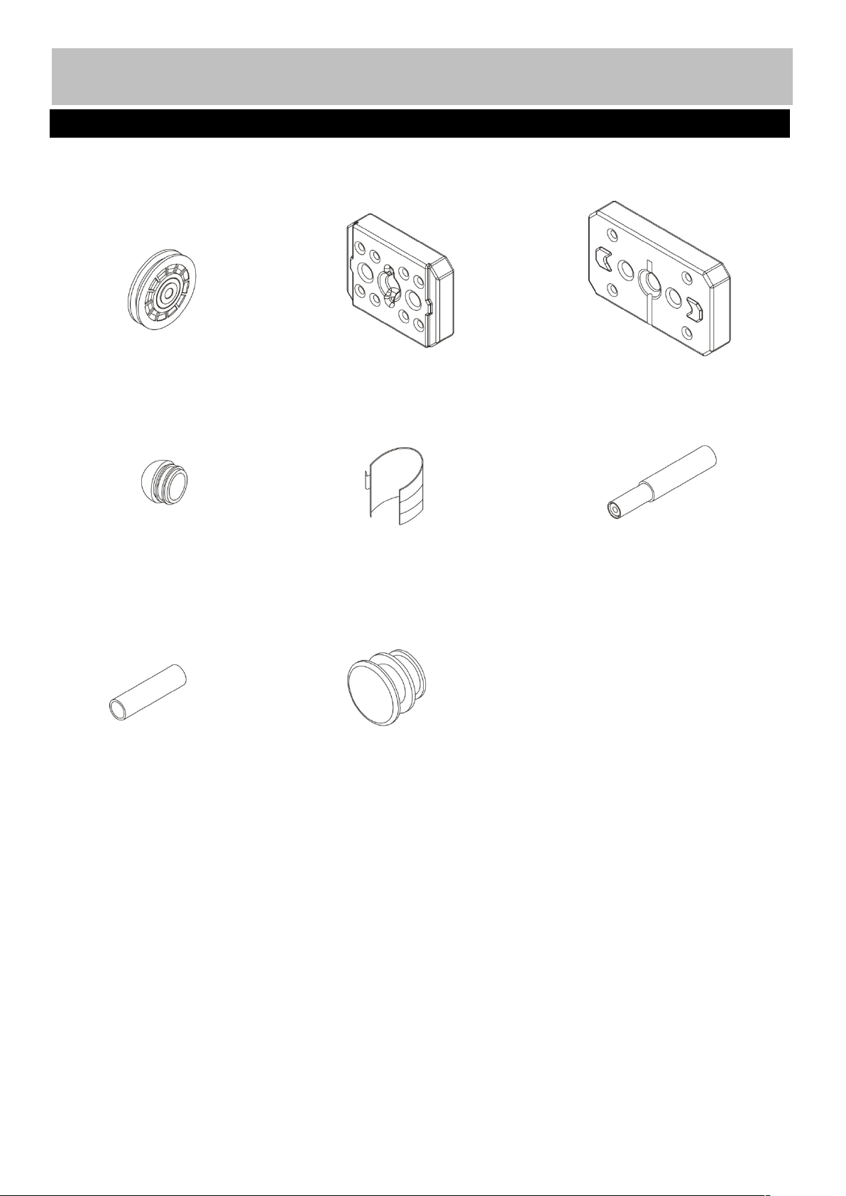
71. Ø78mm Pulley
× 12
72. 8LBS Select
plate × 1
73. 10LBS Weight
plate × 9
74. Ø25mm End cap × 1
76. Ankle strap × 1
Components - Parts
Please check you have all parts listed below
77. Front press handle × 2
78. Front press handle
Grip Ø25×110 × 2
79. Ø25mm End cap × 8
Note: The quantities below are the correct amount to complete the assembly. In some cases more
hardware may be supplied than is actually required. Some of the smaller components may be pre-fitted to
the larger components.
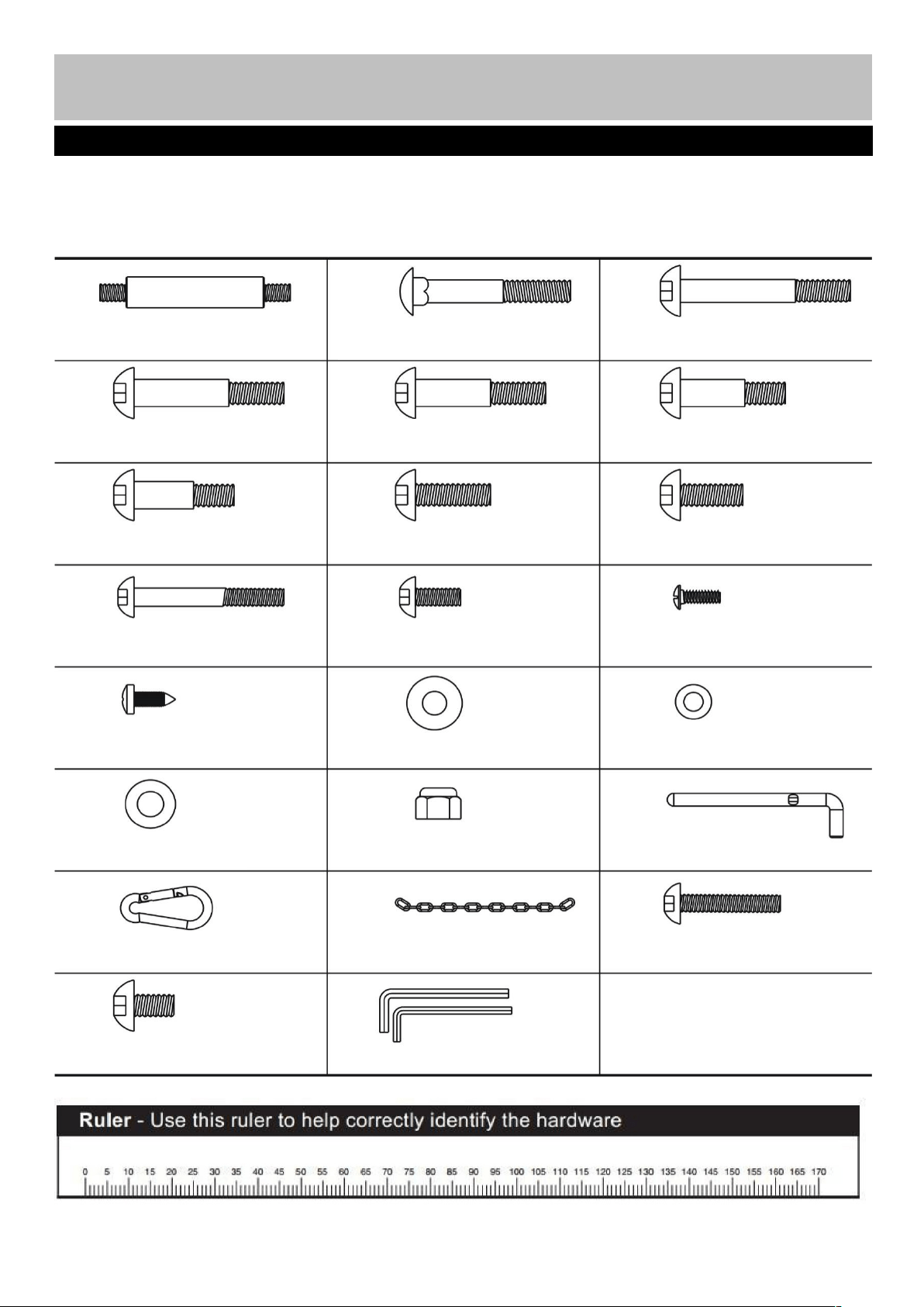
Components - Fixings
8
Please check you have all fixings listed below
M10 × 103mm Axle ×
1
21
M10 × 65mm Carriage bolt × 8
M10 × 65mm Allen bolt × 2
M10 × 60mm Allen bolt × 4
M10 × 55mm Allen bolt × 1
M10 × 42mm Allen bolt × 2
M10 × 40mm Allen bolt × 6
M10 × 30mm Allen bolt × 1
M10 × 25mm Allen bolt × 6
M8 × 18mm Allen bolt × 2
Ø25 x Ø 11 × 1.5 Washer × 4
M6 × 16mm Phillips screw × 1
ST4.8 Phillips screw × 2
M8 × 60mm Allen bolt × 2
Ø 8mm Washer × 6
Ø10 Washer × 40
M10 Aircraft nut × 28
Stack select pin × 1
6# Clip hook × 2
15 Joint chain × 1
M8 × 40mm Allen bolt × 2
27
28
29
30
31
32
33
34
35
36
37
39
38
40
44
42
41
45
47
61
75
M10 × 16mm Allen bolt × 2
Allen Key 5、6mm
Assembly instructions
9
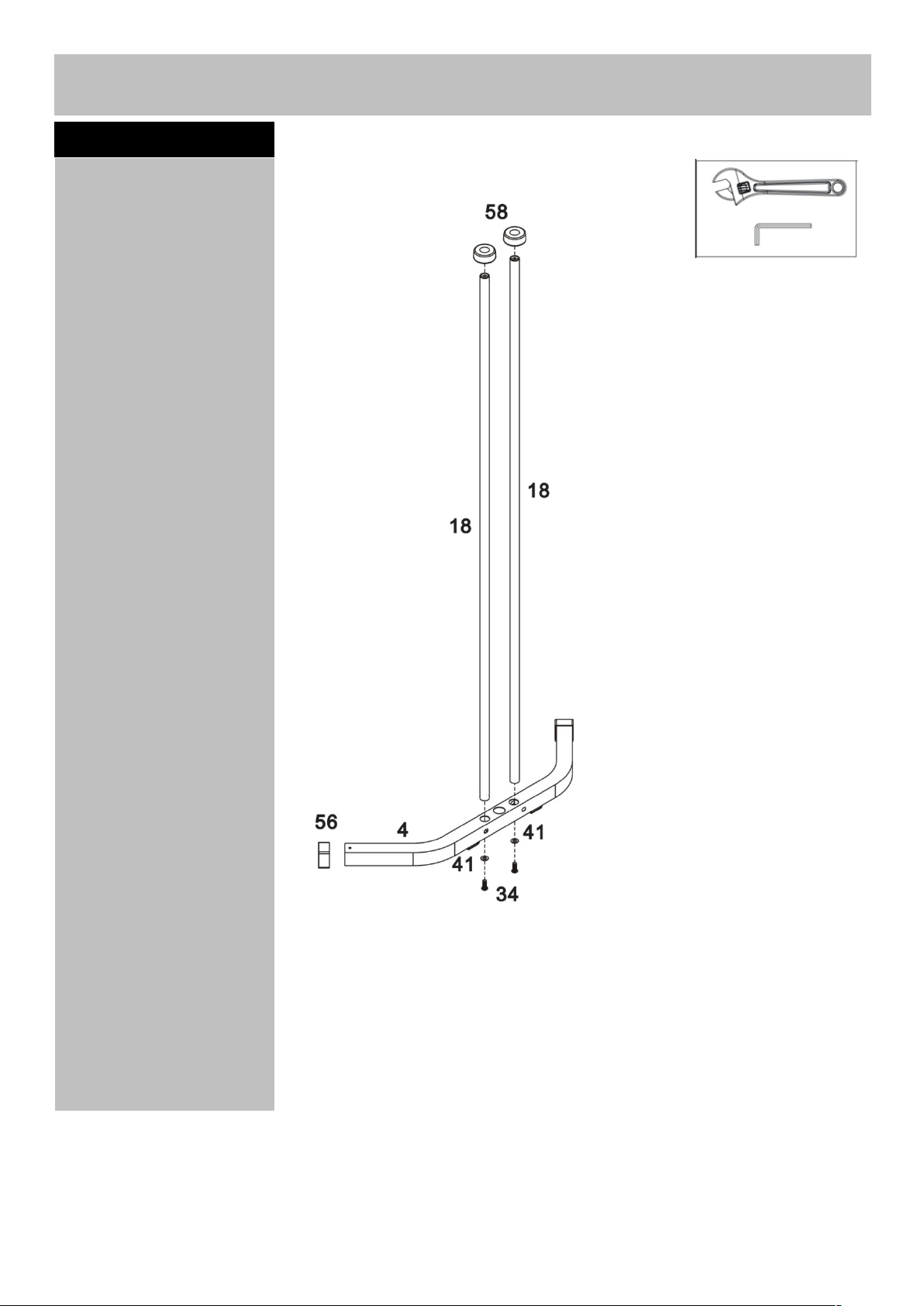
Step 1
a. Insert the Guide rods
(18) into the holes on the
Rear stabilizer (4). Fi
x
using 2 x M10 x 25mm
Allen bolts (34) and 2 x
Ø10mm Washers (41).
b. Slide 2 x Ø61mm
Rubber bumpers (58
)
down onto Guide rods
(18).
Note: (56) was fixed in
the factory.
]
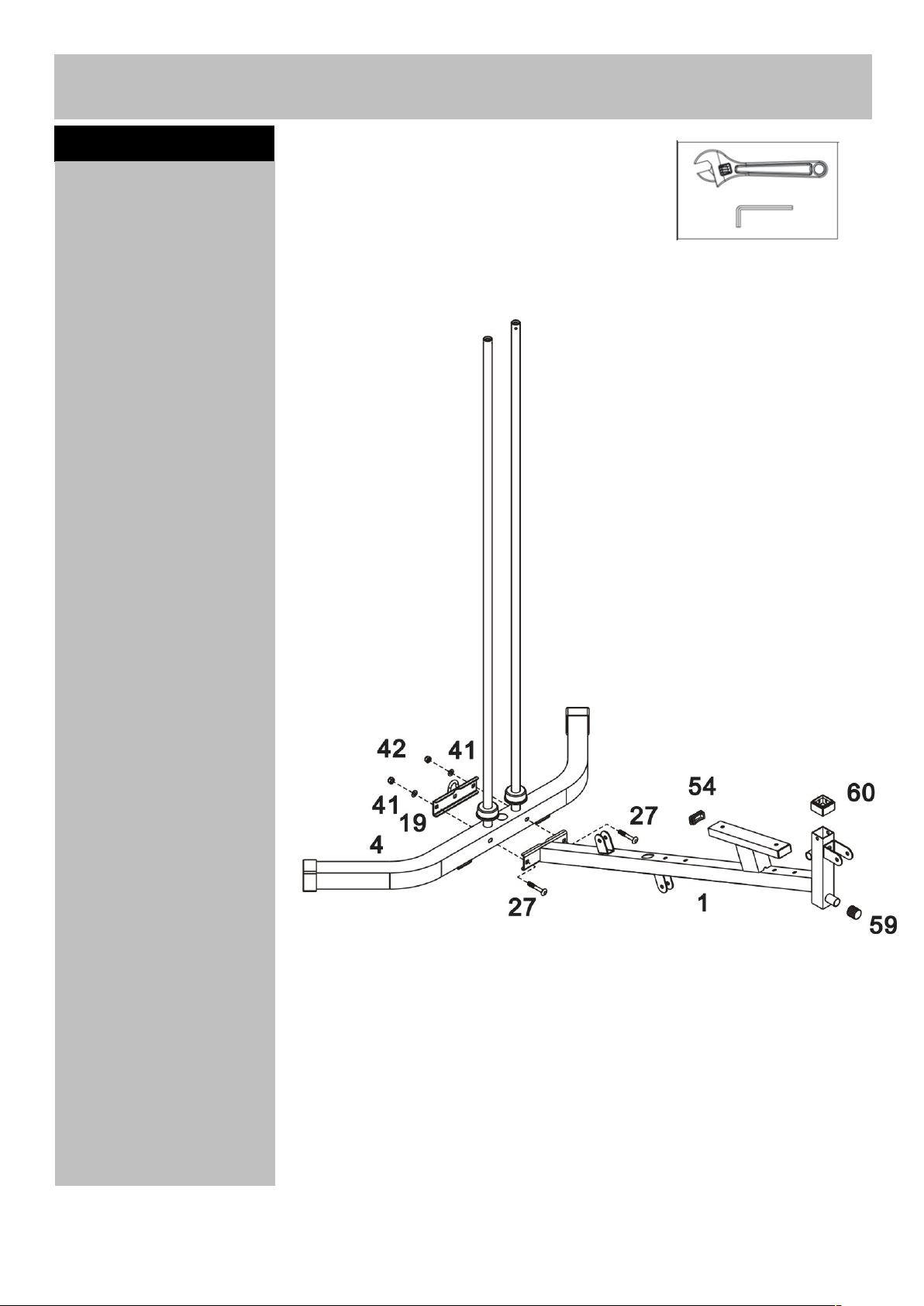
Step 2
Attach the Base frame (1)
to the Rear stabilizer (4).
Fix using 2 x M10x 65mm
Carriage bolts (27), the
Rear U-shaped bracket
(19), 2 x Ø10mm
Washers (41) and 2 x
M10 Aircraft nuts (42).
Assembly instructions
10
11
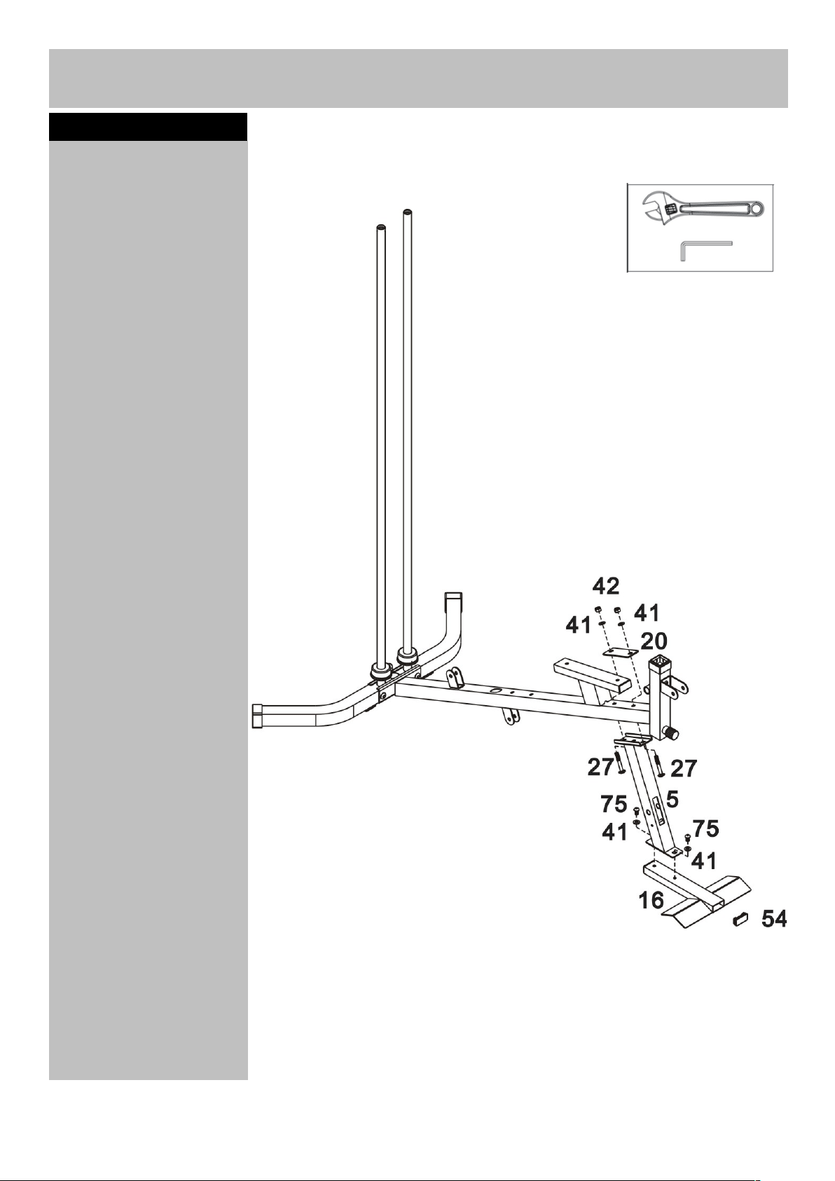
Assembly instructions
a. Attach the Front
stabilizer (16) to the Leg
developer holder (5), fi
x
using 2 x M10 x 16mm
Allen bolts (75), 2
x
Ø10mm Washers (41).
b. Attach the Leg
developer holder (5) to
the Base frame (1) fi
x
using 120mm Bracket
(20), 2 x M10 x 65mm
Carriage bolts (27), 2
x
Ø10mm Washers (41)
and 2 x M10 Aircraft Nut
s
(42).
Note: (54) was fixed in
the factory.
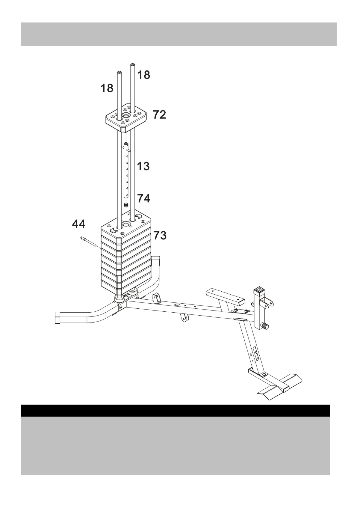
Step 3
Assembly instructions
a. Carefully slide 9x 10LBS Weight plates (73) down Guide rods (18), insert the Select rod (13) into the
Weight plates (73), and then slide 1 x 8LBS Select plate (72) down Guide rods (18)
b. Select the desired training weight by inserting the Stack select pin (44) into the deep grooves under
the Weight plates and into the Select rod.
Note: (74) was fixed in the factory.
Step 4
12
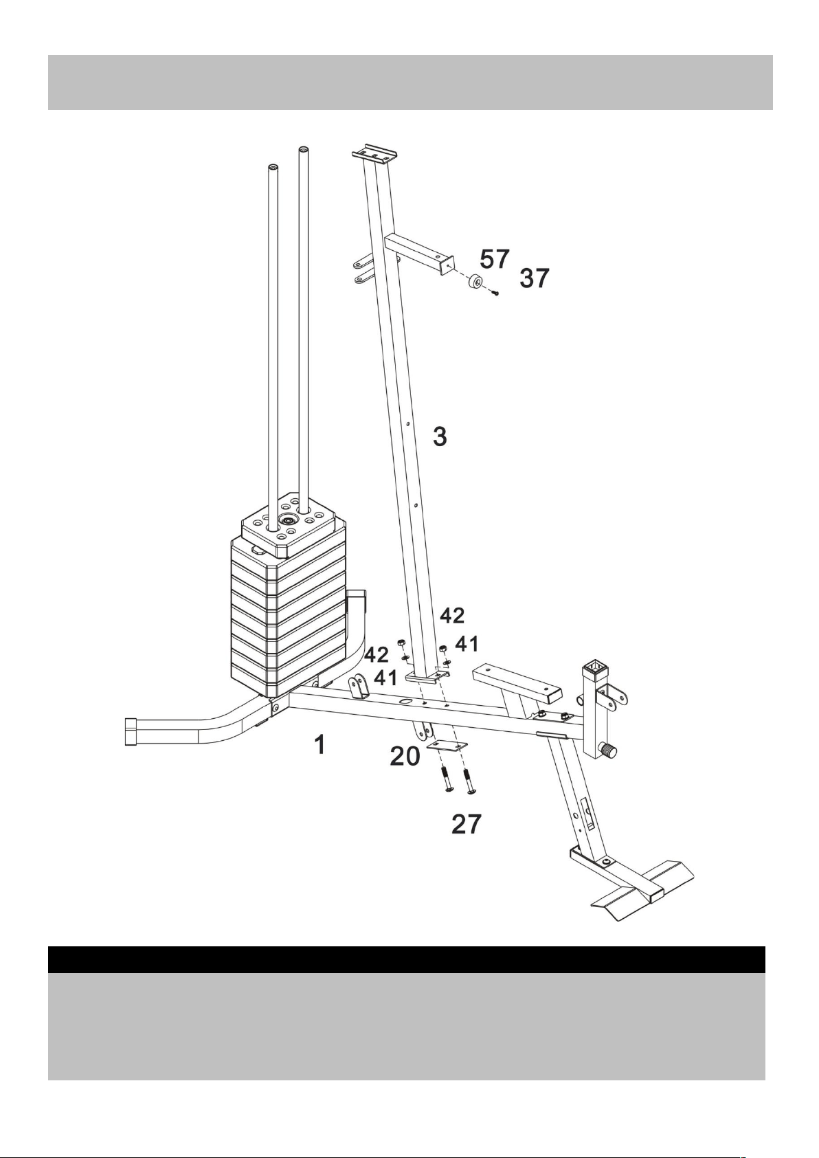
Attach the Vertical frame (3) to the Base frame (1). Fix using 2 x M10 x 65mm Carriage bolts (27),
120mm Bracket (20), 2 x Ø10mm Washers (41) and 2 x M10 Aircraft nuts (42).
Note: (37/57) was fixed in the factory.
Step 5
Assembly instructions
13
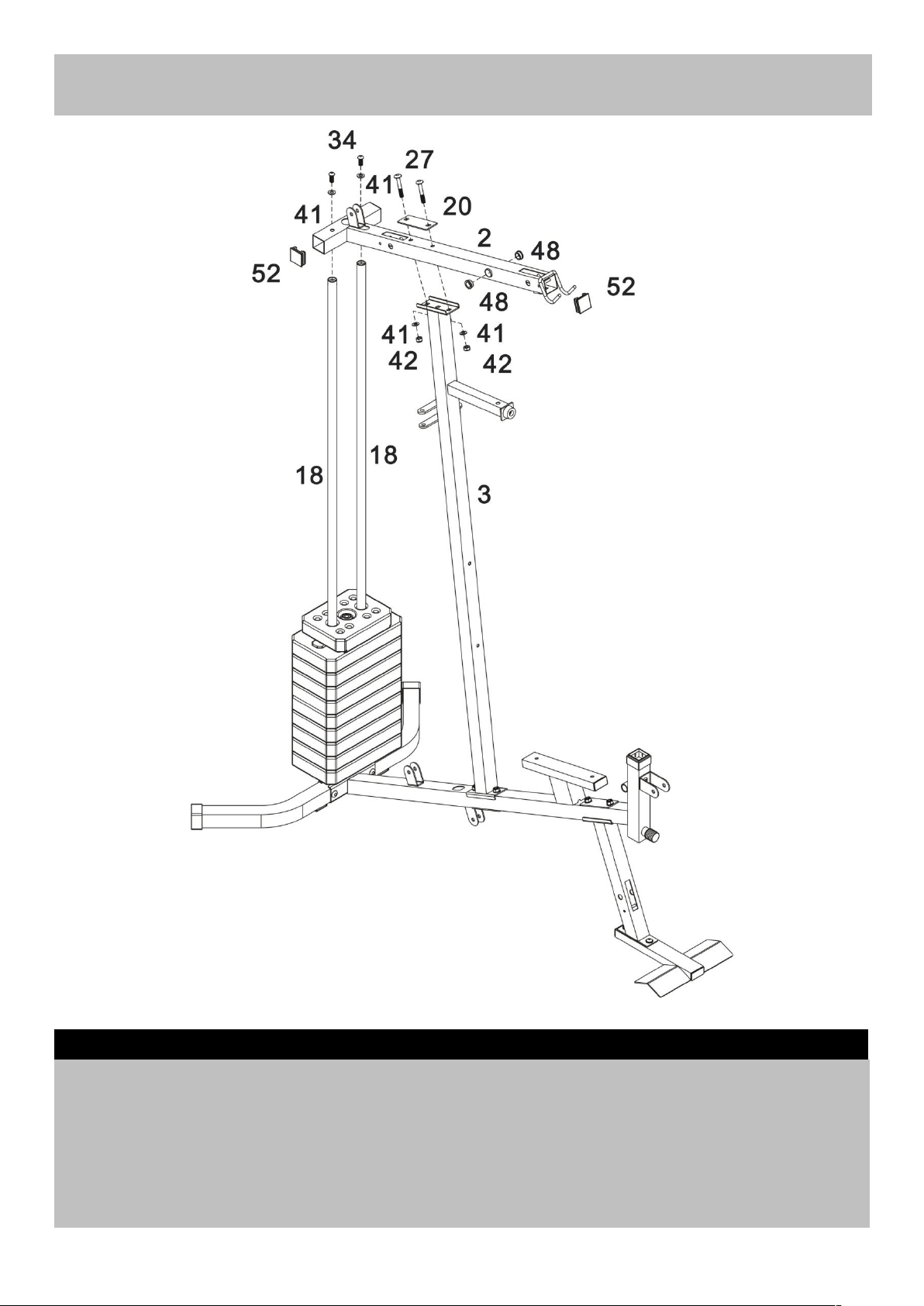
a. Attach Upper frame (2) to Guide rods (18) fix using 2 x M10 x 25mm Allen bolts (34) and 2 x Ø10mm
Washers (41).
b. Attach Upper frame (2) to the Vertical frame (3) fix using 2 x M10 x 65mm Carriage bolts (27)
,
120mm Bracket (20), 2 x Ø10mm Washers (41) and 2 x M10 Aircraft nuts (42),
Note: (52/48) was fixed in the factory.
Step 6
Assembly instructions
14
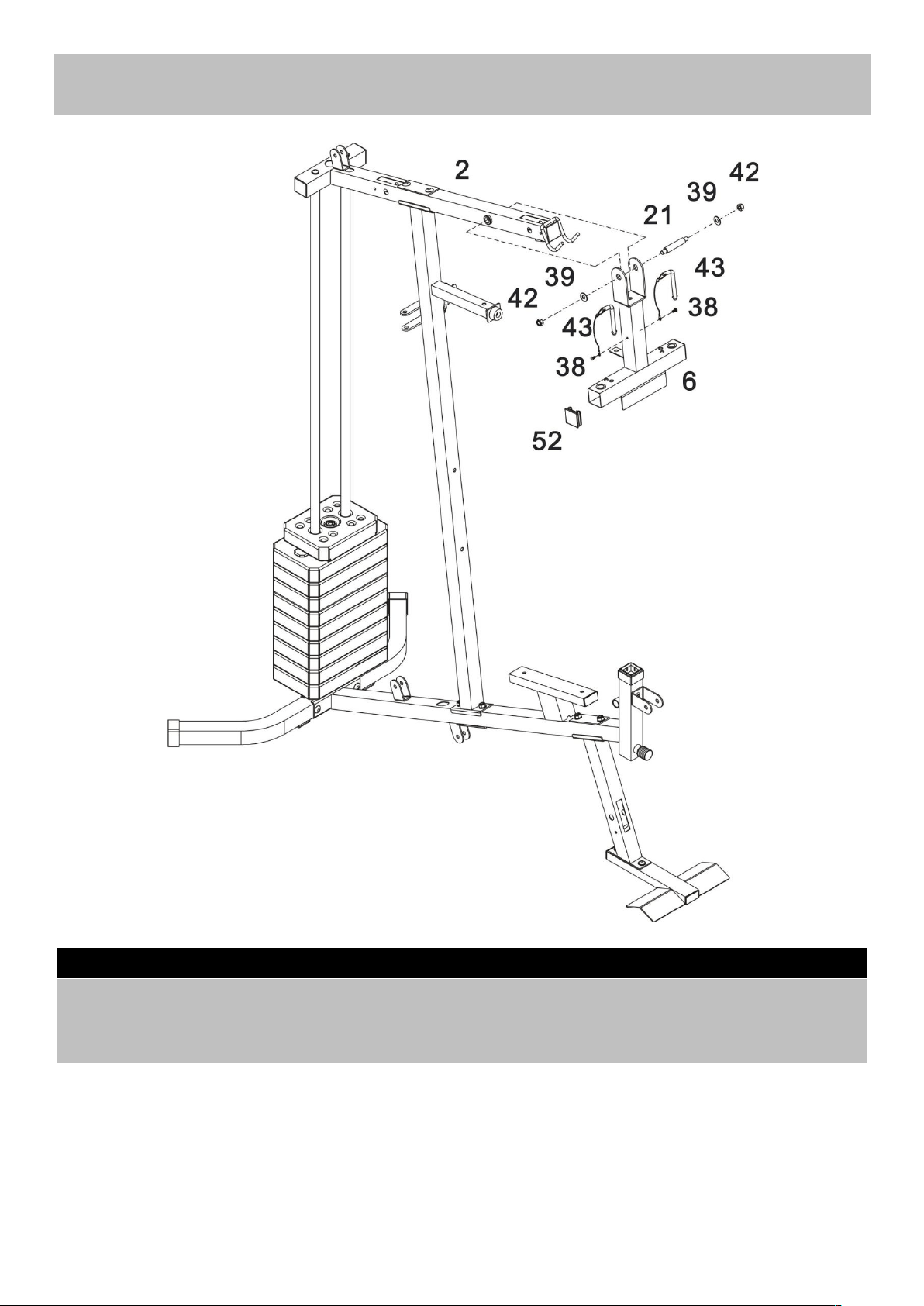
Attach the Front press base (6) to the Upper frame (2) using the M10 x 103mm Axle (21). Secure using
2 x Ø25 x Ø11x1.5 Washers (39) and 2 x M10 Aircraft nuts (42).
Note: (38/43/52) were fixed in the factory.
Step 7
Assembly instructions
15
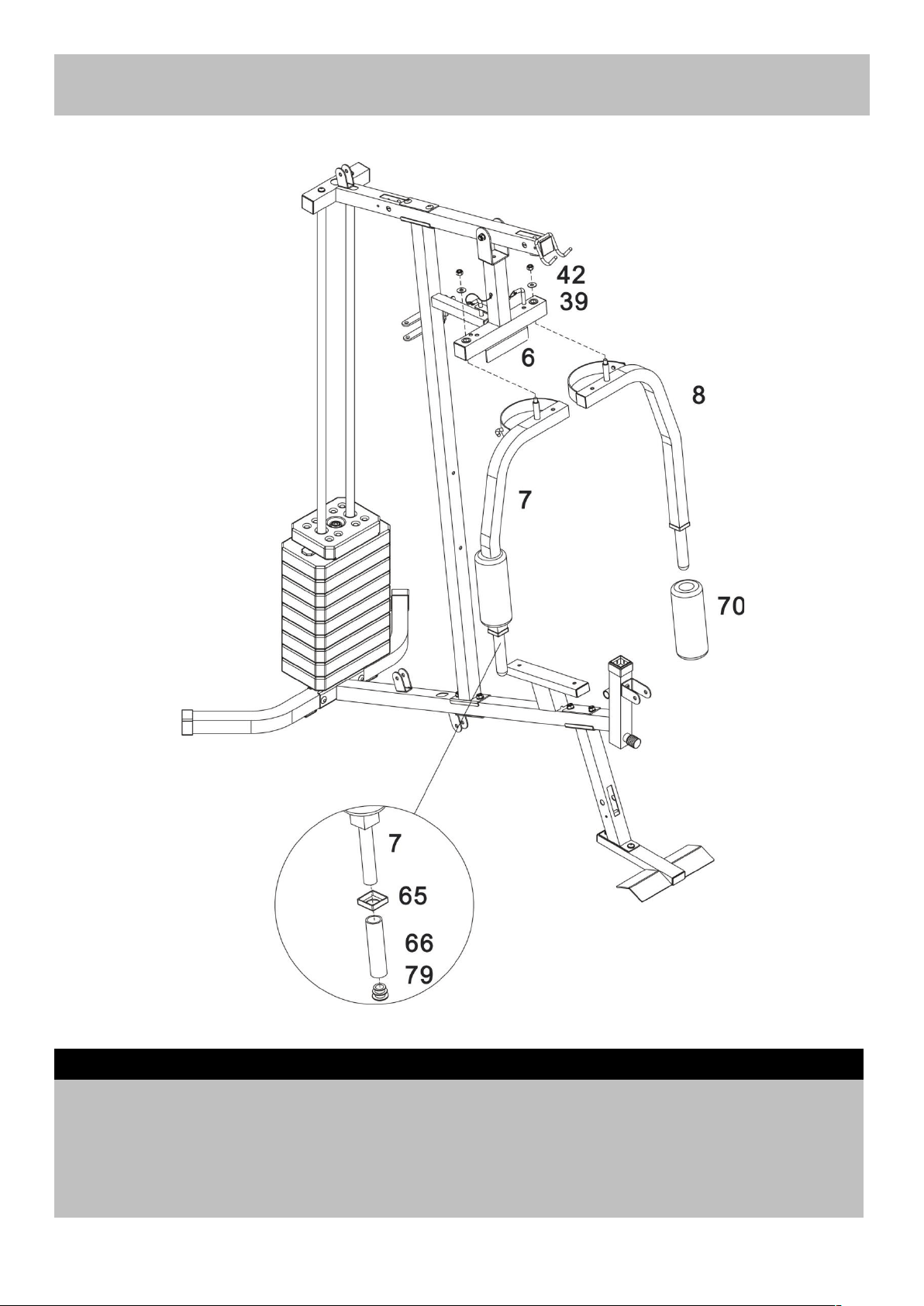
a. Attach the ‘pivots’ on the Right and Left Butterfly’s (7 & 8) to the Front press base (6) using 2 x Ø25 x
Ø11 x 1.5 Washers (39) and 2 x M10 Aircraft nuts (42).
b. Slide the 2 x Ø45mm Foam rolls (70) over the end of the Butterfly’s (7 & 8)
.
Note: (65/66) were fixed in the factory.
Step 8
Assembly instructions
16
Pivot
Pre-fitted
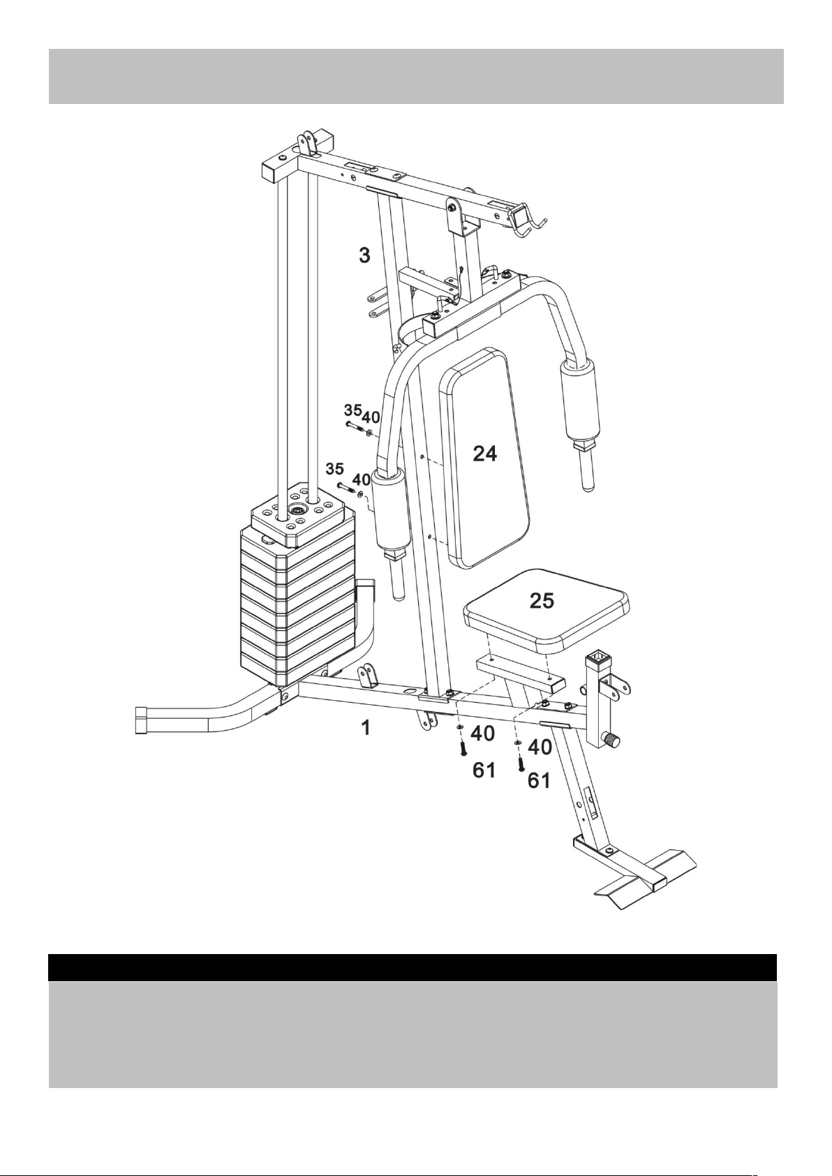
Step 8
a. Attach the Backrest pad (24) to the Vertical frame (3) using 2 x M8 x 60mm Allen bolts (35) and 2 x
Ø8mm Washers (40).
b. Attach the Seat pad (25) to the Base frame (1) using 2 x M8 x 40mm Allen bolts (61) and 2 x Ø8mm
Washers (40).
Assembly instructions
17
Step 9
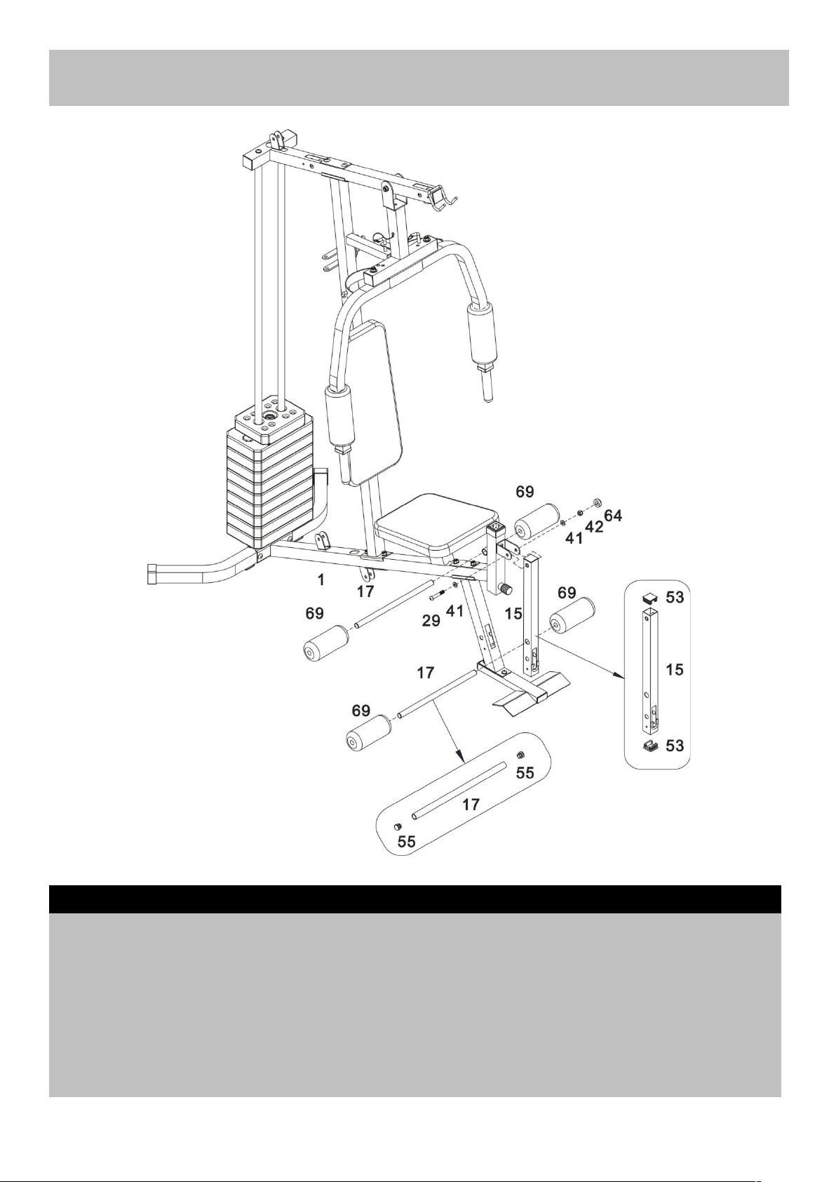
a. Slide the Foam roll tube (17) into the hole on the Base frame (1). Push 2 x Ø17mm Foam rolls (69)
onto each side of the Foam roll tube (17).
b. Attach the Leg developer (15) to the Base frame (1) using M10 x 60mm Allen bolts (29) and 2
x
Ø10mm Washers (41), M10 Aircraft nut (42) and M10 Nut cap (64).
c. Slide the Foam roll tube (17) into the hole on the Leg developer (15). Push 2 x Ø17mm Foam roll
s
(69) onto each side of the Foam roll tube (17).
Note: (53/55) were fixed in the factory.
Step 10
Assembly instructions
18
Pre-fitted
Pre-fitted
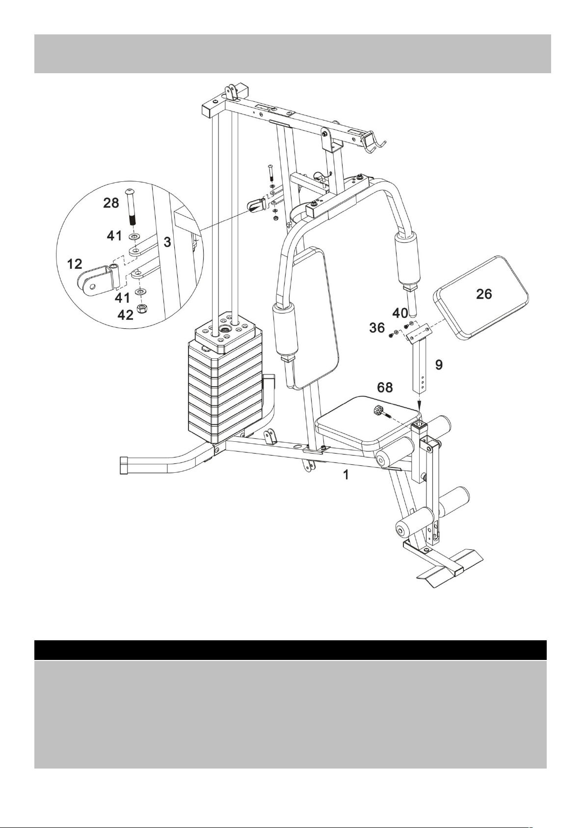
a. Attach the Preacher pad (26) to the Preacher pad stand (9). Secure using 2 x M8 x 18mm Allen bolts
(36) and 2 x Ø8mm Washers (40).
b. Insert the Preacher pad assembly into the Base frame (1). Select the desired height and secure using
the Lock knob (68).
c. Attach 2 x Swivel pulley brackets (12) to the two sides of open bracket on the Vertical frame (3). Fi
x
using 2 x M10 x 65mm Allen bolts (28), 4 x Ø10mm Washers (41) and 2 x M10 Aircraft nuts (42).
Step 11
Assembly instructions
19
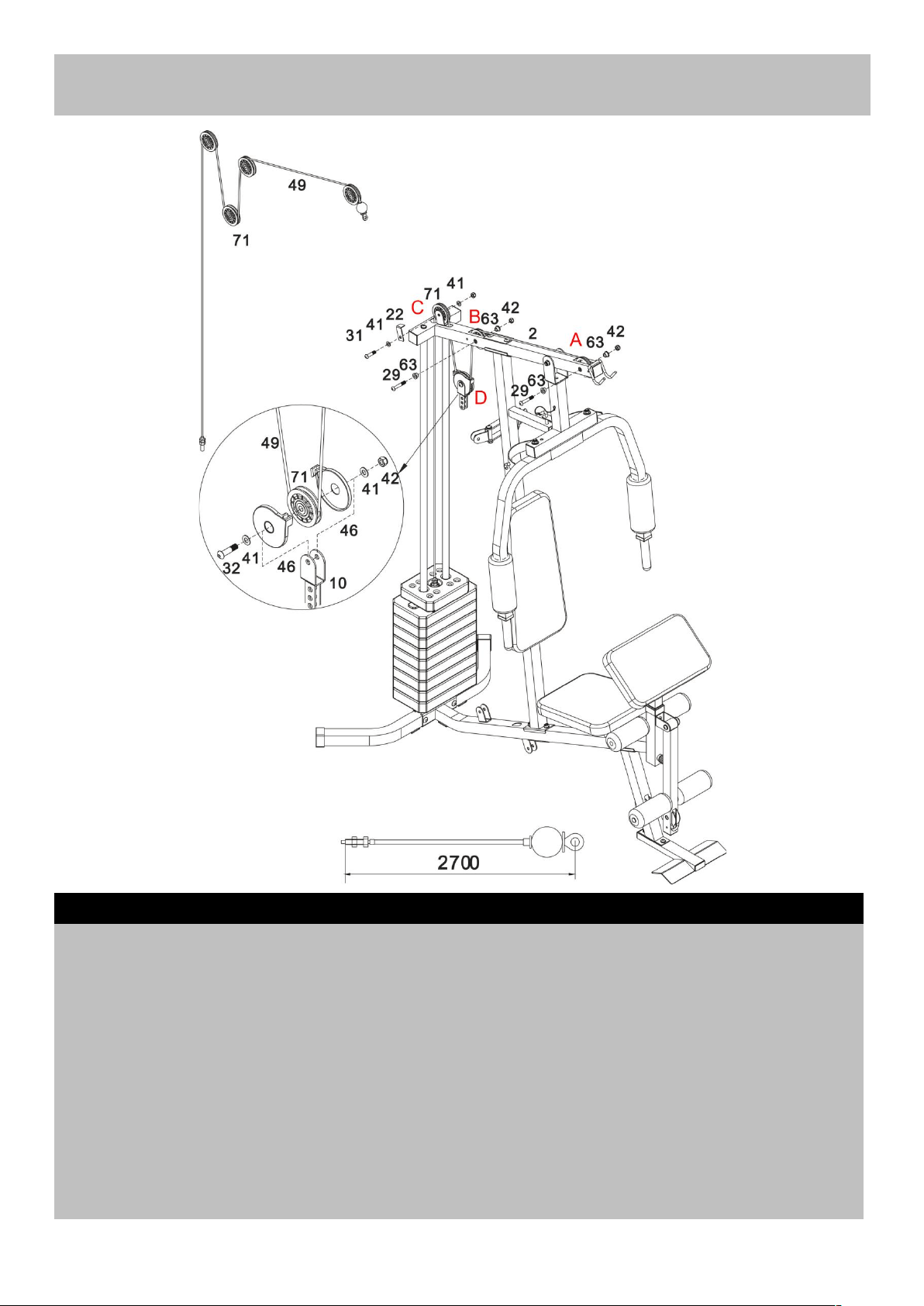
Important: Study and follow the diagram carefully.
a. Feed the bolt end of the 2700mm Upper cable (49) up through opening in Upper frame (2). Insert Ø22
x 15mm Pulley bushings (63) into holes and attach 1st Pulley (71) using M10 x 60mm Allen bolt (29)
and M10 Aircraft nut (42).
b. Repeat procedure for 2nd Pulley, feeding cable up through opening in Upper frame (1).
c. Attach 3rd Pulley to Upper frame (2) using a M10 x 42mm Allen bolt (31), 2 x Ø10mm Washers (41)
,
M10 Aircraft nut (42) and 1 x L-Shaped separation blade (22).
d. Place 4th Pulley (71) onto the cable and fit Pulley covers (46) over Pulley and cable. Attach Pulle
y
assembly to Floating pulley bracket (10) using a M10 x 40mm Allen bolt (32), 2 x Ø10mm Washers (41)
and M10 Aircraft nut (42).
Step 12
Assembly instructions
20
31
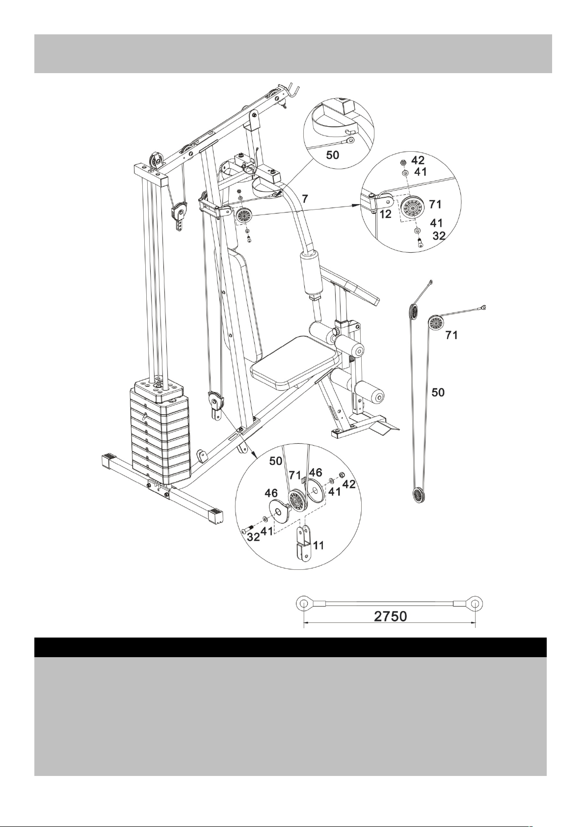
a. Hook one end of the 2750mm Butterfly cable (50) to Right butterfly (7).
Place a Ø77mm Pulley (71) under the cable, position the pulley into the Swivel pulley brackets (12). Fi
x
using M10 x 40mm Allen bolts (32), 2 x Ø10mm Washers (41) and M10 Aircraft nut (42).
b. Repeat “a” to attach the left side.
c. Place a Ø77mm Pulley (71) onto the cable and fit Pulley covers (46) over Pulley and cable. Attach
Pulley assembly to Angle double pulley bracket (11) using M10 x 40mm Allen bolt (32), 2 x Ø10mm
Washers (41) and M10 Aircraft nut (42).
Step 13
Assembly instructions
21
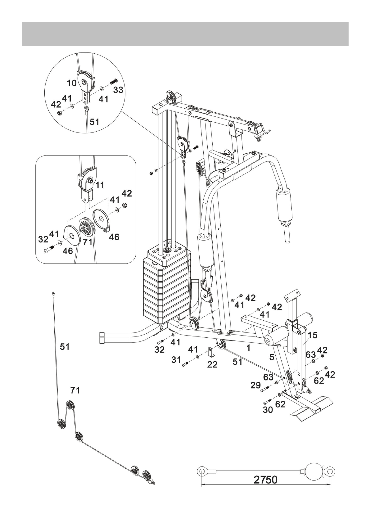
Assembly instructions
22

Important: Study and follow the diagram carefully.
a. Feed the loop end of 2750mm Lower cable (51) through opening in the Leg developer (15). Insert 2 x
Ø22 x 11mm Pulley bushings (62) into holes and attach 1st Pulley using M10 x 53mm Allen bolt (30) an
d
M10 Aircraft nut (42).
b. Insert 2 x Ø22 x 15mm Pulley bushings (63) into holes and attach 2nd Pulley using M10 x 60
mm
Allen bolt (29) and M10 Aircraft nut (42).
c. Attach 3rd Pulley to Base frame (1) using a M10 x 42mm Allen bolt (31), 2 x Ø10mm Washers (41)
,
M10 Aircraft nut (42) and 1 x L-Shaped separation blade (22).
d. Place 4th Pulley onto the cable and fit Pulley covers (46) over Pulley and cable. Attach Pulley
assembly to the other end of the Angled double pulley bracket (11) using M10 x 40mm Allen bolt (32), 2
x Ø10mm Washers (41) and M10 Aircraft nut (42).
e. Attach 5th Pulley to Base frame (1) using M10 x 40mm Allen bolt (32), 2 x Ø10mm Washers (41) an
d
M10 Aircraft nut (42).
f. Secure the end of the Lower cable (51) to the Floating pulley bracket (10) using M10 x 30mm Allen bolt
(33), 2 x Ø10mm Washers (41) and M10 Aircraft nut (42).
Step 14
23
Assembly instructions
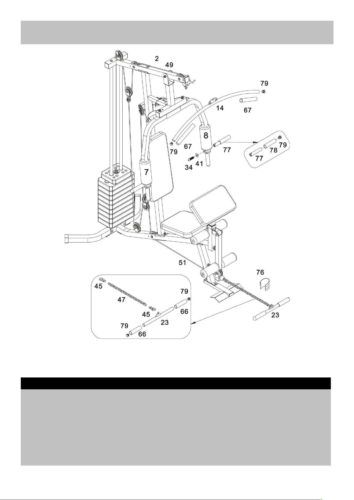
Important: Now fully tighten the fixings ensuring that all of the pulleys and brackets can move freely.
Attach the Lat bar (14) onto the Upper frame (2) hooks.
Connect the Pull bar (23) to the end of Lower cable (51) using 2 x Clip hooks (45) and 15 Joint chain
(47).
Attach 2 x Front press handle (77) to the Right/Left butterfly (7&8). Fix using 2 x M10 x 25mm Allen
bolt (34) and 2 x Ø10mm Washers (41).
Note: (66/67) was fixed in the factory.
Step 15
Assembly instructions
24

Part
Description
Qty.
Part
Description
Qty.
1
Base frame
1
22
L-Shaped separation blade
2
2
Upper frame
1
23
Pull bar
1
3
Vertical frame
1
24
Backrest pad
1
4
Rear stabilizer
1
25
Seat pad
1
5
Leg developer holder
1
26
Preacher pad
1
6
Front press base
1
27
M10 x 65mm Carriage bolt
8
7
Right butterfly
1
28
M10 x 65mm Allen bolt
2
8
Left butterfly
1
29
M10 x 60mm Allen bolt
4
9
Preacher pad support
1
30
M10 x 55mm Allen bolt
1
10
Floating pulley bracket
1
31
M10 x 42mm Allen bolt
2
11
Angle double pulley bracket
1
32
M10 x 40mm Allen bolt
6
12
Swivel pulley bracket
2
33
M10 x 30mm Allen bolt
1
13
Select rod
1
34
M10 x 25mm Allen bolt
6
14
Lat bar
1
35
M8 x 60mm Allen bolt
2
15
Leg developer
1
36
M8 x 18mm Allen bolt
2
16
Front stabilizer
1
37
M6 x16mm Phillips screw
1
17
Foam roll tube
2
38
ST4.8 Philips screw
2
18
Guide rod
2
39
Ø25 x Ø11 x 1.5 Washer
4
19
Rear U-shaped bracket
1
40
Ø8mm Washer
6
20
120mm Bracket
3
41
Ø10mm Washer
40
21
M10 x 95mm Axle
1
42
M10 Aircraft nut
28
Exploded Parts List
33

43
Seated press lock pin
2
62
Ø22mm x 11mm Pulley bushing
2
44
Stack select pin
1
63
Ø22mm x 15mm Pulley bushing
6
45
6# Clip hook
2
64
M10 Nut cap
1
46
Pulley cover
6
65
Ø26mm x 38mm Hollow sleeve
2
47
15 Joint chain
1
66
Front press handle grip Ø25×130
4
48
Ø25mm ×31mm Bushing
2
67
Lat pull handle grip
2
49
2700mm Upper cable
1
68
Lock knob
1
50
2750mm Butterfly cable
1
69
Ø17mm Foam roll
4
51
2750mm Lower cable
1
70
Ø45mm Foam roll
2
52
45mm End cap
5
71
Ø77mm pulley
12
53
38mm End cap
4
72
8LBS Select plate
1
54
25×50mm End cap
4
73
10LBS Weight plate
9
55
Ø19mm End cap
4
74
Ø25mm End cap
1
56
Rear stabilizer end cap
2
75
M10×16mm Allen Bolt
2
57
Ø37mm Rubber bumper
1
76
Ankle strap
1
58
Ø61mm Rubber bumper
2
77
Front press handle
2
59
30mm Rubber bumper
1
78
Front press handle grip Ø25×110
2
60
45mm x 38mm Sleeve
1
79
Ø25mm End cap
8
61
M8 x 40mm Allen bolt
2
Exploded Parts List
34

GARLANDO SPA
Via Regione Piemonte, 32 - Zona Industriale D1
15068 - Pozzolo Formigaro (AL) - Italy
www.evert.it - info@evert.it