Loading ...
Loading ...
Loading ...
Pr
ocedure Illustration
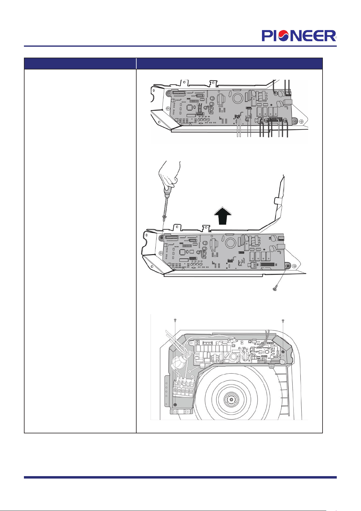
3) Disconnect the connectors of
PCB (see Figure 8).
4) Remove 2 screws of main
control board and remove PCB (see
Figure 9).
5) Remove 2 screws of electronic
control box and remove electronic
control box (see Figure 10).
Figure 8
Figure 9
Figure 10
Note: This section is for r
eference only. Actual unit appearance may vary.
Page 5
Loading ...
Loading ...
Loading ...