Loading ...
Loading ...
Loading ...
ASSEMBLY INSTRUCTIONS
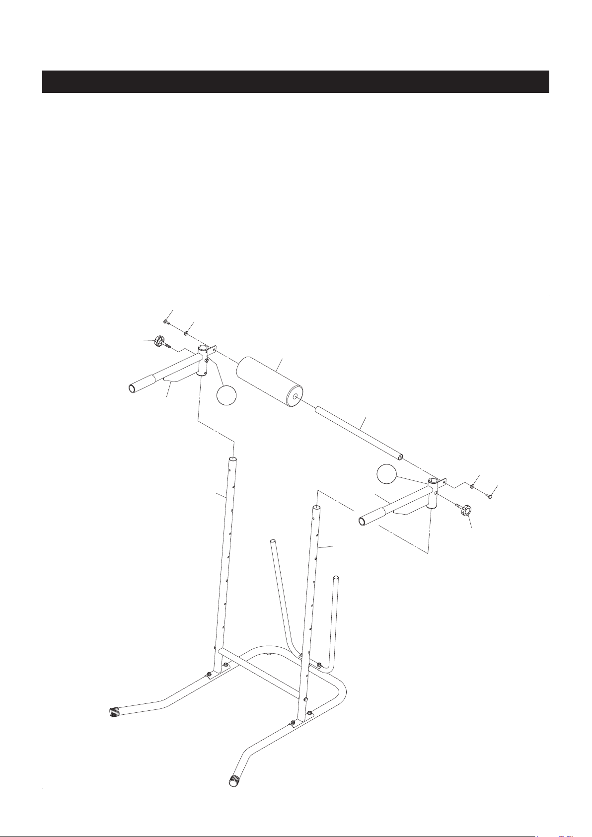
STEP 3
There is an “R” decal on the RIGHT DIP ARM(9), and an “L” decal on the LEFT DIP ARM(10). Insert
the LEFT DIP ARM(10) onto the LOWER UPRIGHT(3) on the left side and lock in position with the
ADJUSTMENT KNOB(19). Repeat on other side. Make sure to set the RIGHT and LEFT DIP ARMS
(9, 10) to the same height.
STEP 4
Insert the FOAM TUBE(12) through the FOAM PAD(22), then attach the assembly to the RIGHT and
LEFT DIP ARMS(9, 10) with HEX BOLTS(M10x1.5x25mm)(34) and WASHERS(M10)(39).
NOTE: There are seven adjustment holes on the LOWER UPRIGHTS(3) for attaching the DIP ARMS
(9, 10) to dierent heights. Remove the ADJUSTMENT KNOBS(19) to adjust.
8
9
12
10
19
19
22
34
34
39
39
3
3
RIGHT
LEFT
L
R
Loading ...
Loading ...
Loading ...