Loading ...
2 JL AUDIO 12W6v3-D4
SUBWOOFER 12W6v3-D4
Free Air Resonance (Fs): 26.919 Hz
Electrical “Q” (Qes): 0.487
Mechanical “Q” (Qms): 9.365
Total Speaker “Q” (Qts): 0.463
Equivalent Compliance (Vas):
1.920 ft
3
54.37 liters
One-way, Linear Excursion
(Xmax)*:
0.75 in
19 mm
Efficiency (1W/1m)**: 85.4 dB SPL
Effective Piston Area (Sd):
75.338 in
2
0.0486 m
2
DC Resistance (Re)***: 6.493 ohm
Nominal Impedance:
Dual 4-ohm
voice coils
Power Handling (continuous): 600 W
A
B
E
D
C
12W6v3 SUBWOOFER
PHYSICAL SPECIFICATIONS
Nominal Diameter:
12.0 in
300 mm
Overall Diameter (A):
12.50 in
318 mm
Mounting Hole Diameter (B):
11.02 in
280 mm
Bolt Hole Circle (C):
11.86 in
301 mm
Magnet Diameter (D):
7.0 in
178 mm
Mounting Depth (E):
7.52 in
191 mm
Required Pole-Vent Clearance:
0.50 in
12.5 mm
Net Weight:
25.6 lbs
11.6 kg
Driver Displacement:
0.105 ft
3
2.97 liters
JL AUDIO 12W6v3-D4
U.S. PATENTS: 6,535,613 #6,118,884 #6,219,431 #6,229,902 #6,501,844 • Other U.S. & Foreign Patents Pending
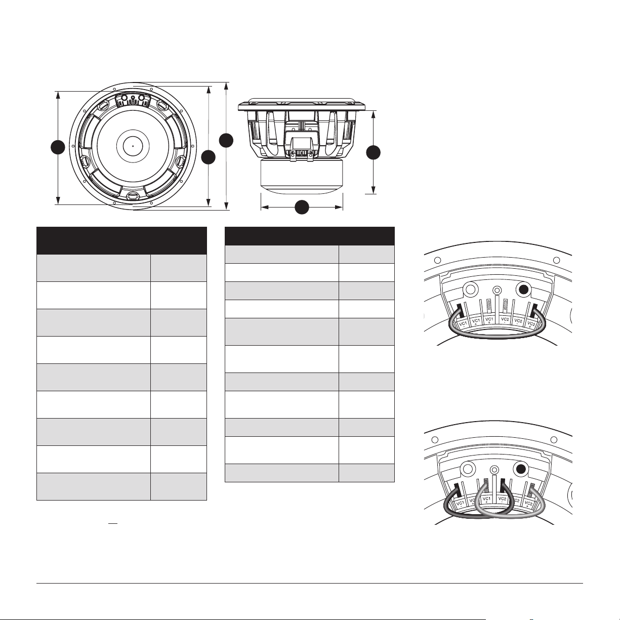
W6v3 Terminal Jumper System
Please note that the W6v3 is a dual voice coil driver.
BOTH voice coils must be connected to the amplifier
(in series or parallel) for the speaker to operate
properly. To accomplish this, each W6v3 features a
pair of main input connection push-terminals and
four voice coil configuration tab terminals. These are
located behind the main input connectors and are
used to interconnect the dual voice coils in one of
two ways: Diagram A shows a series connection
(8Ω nominal impedance per speaker). Diagram B
shows a parallel connection (2Ω nominal impedance
per speaker) and is the way the speaker is configured
at the factory. After verifying that the tabs are
properly configured using the supplied jumper(s),
connect the amplifier’s output wires to the W6v3s
main input push-terminals and install the speaker
into the enclosure.
All specifications are subject to change without notice.
Diagram A: Series Connection (8Ω):
Use one jumper from “VC1–” to “VC2+”
Warning! Failure to properly connect the
configuration tabs will result in no output and
may damage the speaker.
Diagram B: Parallel Connection (2Ω):
Use two jumpers... one from “VC1–” to “VC2–” and
one from “VC1+ to “VC2+”.
* Xmax specifications are derived via one-way voice coil overhang method with no correction factors applied.
** Efficiency (1W/1m) is not an accurate indicator of a subwoofer’s output capability and should not be used as a comparison to
other subwoofers to determine which one is “louder” !
*** Re (DC resistance) is measured with the voice coils in series, for parallel-wired specification divide Re by 4. All other
specifications remain the same.
Loading ...
Loading ...