As instrument products have many functions and frequent software and hardware updates, the manual may be updated at any time,please be aware.Please get the latest update information on the official website.
2. Overview
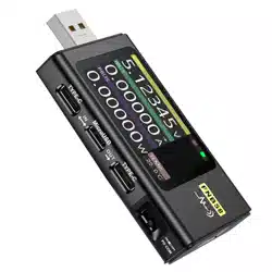
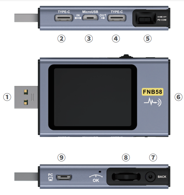
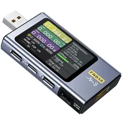
The FNB58USB tester is a high-reliability, high-safety USB voltage and current detection meter and a mobile communication terminal fast charging trigger.It has a 2.0-inch full-color ultra-wide viewing angle TFT LCD display, integrated USB-A, Micro-USB, Type-C interface. Use external 16-bit ADC, PD protocol physical chip. It can be used to measure the power supply or power consumption of products such as USB interfaces, mobile phone chargers, and U disks; it can be used to measure the charging power of mobile phones and the input and output of mobile power supplies; it can be used to test the fast charging protocol of chargers.
This instruction manual includes relevant safety information,warning tips and solutions to common abnormal situations. Please read the relevant content carefully and strictly abide by all warnings and precautions.
3. Safety precautions
Do not connect the monitoring interface to a power supply exceeding 28V;
Do not connect the PC connection port to a power source exceeding 16v;
Only one pair of monitoring interfaces (one input port,one out put port) can work at the same time. When there is a pair of monitoring interfaces working, it is forbidden to connect to the equipment onother monitoring interfaces. (Except the PC connection port, the PCport can be connected to an external power supply)
When using the fast charge trigger module,please do not connect equipment that cannot withstand high voltage to any monitoring interface;
After using the PD trigger/monitor/conversion/read E-Marker cable function,please turn the PD communication switch in the lower right corner back to the OFF position;
Do not charge the phone after the fast charge is triggered, Therefore,the phone is damaged,the manufacturer is not responsible for any damage to the phone.
4. Performance description
4.0.1 Voltage and Current
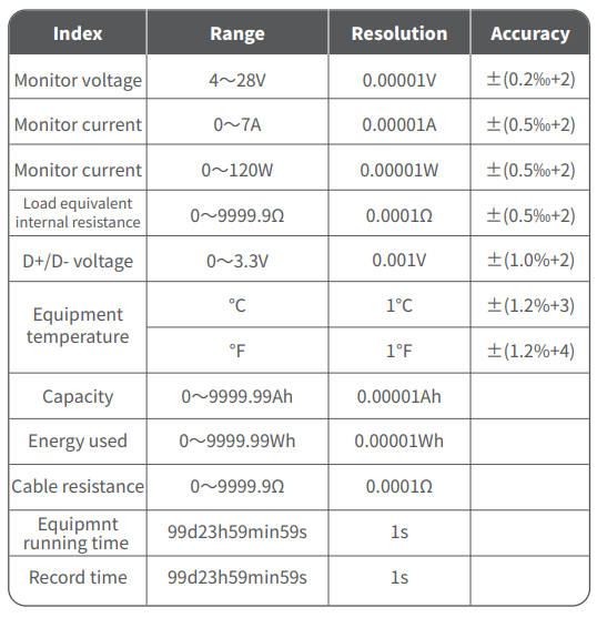
1.The highest six-digit display of voltage,current and power,the highest resolution is 0.00001 (V/A/W).
2. 10 sets of switchable capacity,power,and time statistics;
3. l set of voltage and current curve records,maximum support 9 hours
Except for special instructions,the left and right buttons switch pages/menus,the middle button confirms,and the BACK button cancels/returns.
Long press the BACK button to turn off the screen backlight, all pages are valid.
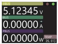
7.0.1 Concise page
Only the three key parameters of voltage,current and power are displayed,indicates the direction of current.
Middle-click to toggle between Run and Pause.
Temperature display (onboard temperature).
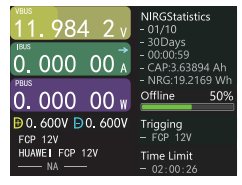
7.0.2 monitoring page
Press the middle button to enter the recallable function menu
-Previous group -Next group -Start recording offline -Clear offline records -Start the time limit
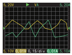
7.0.3 Waveform page
Long press the left button: time base minus.
Long press the right button: time base plus
Click the middle button: start/pause drawing the curve.
Long press the middle button: switch modes.
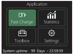
7.0.4 Application page
Application
Fast Charge
Statistics
Toolbox
Settings
8. Fast Charge
In the application interface, press the middle button to enter the fast charging application. When entering the fast charging application, a warning will pop up. Please read carefully and press the middle button to confirm the entry.
After entering, use the left and right keys to select options as follows:
1.Automatic detection
2.PD Trigger
3.QC2.0
4.QC3.0
5.FCP
6.SCP
7.AFC
8.VOOC/WARP
9.SVOOC 1.0
10.SVOOC 2.0
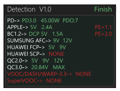
8.0.1Automatic detection
In the fast charging interface, select automatic detection and press the middle button to enter
In this mode, The meter tries to trigger various protocols in turn, Display the test results on the screen,Red is not supported,Green issupport, In the process of testing, Such as measuring PD chargers,It is normal to restart and continue testing.
During the test, it is forbidden toconnect to any equipment at the back end.
It does not respond to any key operation during the test. If you wantto exit during the test,please unplug the meter directly.
After the testis completed,click the middle button to start the test again; click theBACK button to return to the previous page.
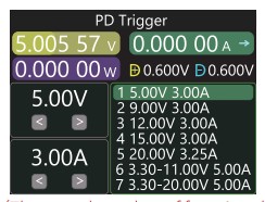
8.0.2 PD Trigger
(The actual number of functional files of the product shall prevail)
In the fast charge interface, select PD trigger and press the middle button to enter
Switch the PD communication switch to ON to enter the PD protocol trigger mode. After exiting the PD trigger, please switch the PD communication switch to OFF.
Press the middle button to select the adjustment window (the window border turns green).
Take the picture as an example, the picture shows a charger sending a message, a total of 7 files, its the 1st, 2nd, 3rd, 4th, and 5th gears are fixed voltage gears, currently adjustable the window is gear adjustment, you can select the gear by the left and right keys, such as when in the voltage/current window, the voltage/current can be adjusted.
Click BACK to pop up the exit/return menu selection window.
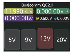
8.0.3 QC 2.0 Trigger
In the fast charge interface, select QC2.0 and press the middle button to enter
In QC2.0 trigger mode,use the left and right keys to select the trigger voltage,click the middle button to confirm the trigger voltage, and click BACK to pop up the exit/return menu selection window.
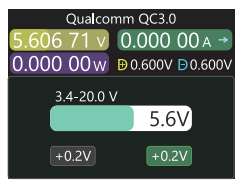
8.0.4 QC 3.0 Trigger
In the fast charge interface, select QC3.0 and press the middle button to enter
In QC3.0 trigger mode, use the left and right keys to decrease/increase Add trigger voltage, click BACK to pop up the exit/return menu Single selection window.
Press the left/right button to quickly decrease/increase the voltage.
8.0.5 FCP Trigger
The operation method is the same as QC2.0 trigger.
8.0.6 SCP Trigger
The operation mode is the same as QC3.0 trigger
8.0.7 AFC Trigger
The operation method is the same as QC2.0 trigger.
8.0.8 VOOC/WARP Trigger
The operation mode is the same as QC3.0 trigger
8.0.9 SVOOC 1.0/SVOOC 2.0 Trigger
Super vooc requires a load greater than 500mA on the back end to deceive, And Super Vooc only has a voltage of 10.5V, Therefore,you can only press BACK to return /exit the page ,and there is no other operation.
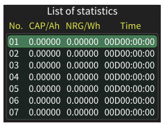
9. Energy statistics
In the application interface, select energy statistics and press the middle button to enter the statistics page. The function options are as follows, and the left and right buttons are used to select Press the middle button to enter each function option
From left to right are the group number, capacity, energy, the selected The group is displayed in green, and time is the statistical time.
Press the left and right keys to switch the group number, press the middle key to choose to set it as "record Record/Clear".
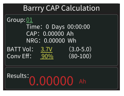
9.0.2 Battery capacity calculation
1. Set the battery voltage and energy conversion efficiency to calculate the battery capacity. Click the middle button to move the green color among the three items of group number, battery voltage and conversion efficiency. Which item is green, and the value of which item can be changed by clicking the left/right button. Each item is explained below.
2. The group number is the statistical group selected for calculation. The instrument can be selected from 1-10 groups. The time, capacity and energy are counted and displayed in order from top to bottom on the right side of the selected group number.
3. The battery voltage, the default is 3.7V, this parameter can be selected from 3.0-5.0V, the actual value please refer to the relevant information.
4. Conversion efficiency is energy conversion efficiency, the default is 90%, this parameter can be selected from 80%-100%, the actual value should be set according to the actual conversion efficiency of the battery.
5. The red letter is the calculation result. If you want to get the result in mAh, please convert it by x1000
9.0.3 Offline recording
After pressing the middle button to enter, press the middle button again to select "Start Offline Recording/Clear Offline Recording"
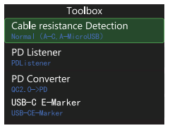
10. Toolbox
In the application interface, select the toolbox and press the middle button to enter the toolbox page. The function options are as follows. Select the left and right buttons and press the middle button to enter each function option.
Cable resistance detection
PD listener
PD converter
USB-C electronic label (e-marker detection)
Read DASH cable
Simulated DASH
Analog APPLE 2.4A
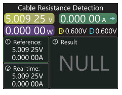
10.0.1Cable resistance detection
FNB58 uses the differential pressure method to measure the internal resistance of the cable, which needs to be used with a constant current load. Click the middle button: use the current voltage and current value as the reference value.
Measurement steps
1. Connection method: charger + FNB58 + constant current load (the current is adjusted to about 0.5-1A), press the middle button to record the reference value.
2. Connection method: charger + cable + FNB58 + constant current load (the current should be adjusted to about 0.5-1A, which should be similar to the current when the reference value was recorded), the system automatically calculates the internal resistance of the cable.
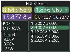
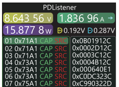
10.0.2 PD Listener
When using PD listener, Need to turn the PD communication switch to ON, And use a power supply not greater than 16V (usually 5V) and a Micro-USB cable,Connect the PC online port,Provide external power.
Use the PD listener function, Need 2 C-C cables,Connect the charger and PD electrical appliances from the Type-CIN interface and Type-COUT interface respectively. When the connection is normal and the PD protocol triggered by the PD consumer is captured,The page is represented as shown below.
When the PD charger cannot be powered,Because the C-C cablehas only one-sided CC,And the 2 CCs are not connected,So you can flip one of the C-C cable connectors,Solve the problem.
The figure below,The charger is a 65W PD charging head,The current PD appliance chooses the second gear,Trigger the target voltage 9V,Maximum current 3A.
Note:
1 Open the settings menu -> trigger -> block PDCRC, you can turn off the monitoring of CRC.
2 For the meaning of various messages in the PD protocol, please refer to the relevant information.
10.0.3 PD Converter
This function is used for only QC2.0 charger, But want to supply power to PD appliances.
Before use, Switch the PD communication switch to ON, Then enter the PD protocol conversion mode,after entering,Plug in PD appliances, You can performPD fast charge.
In this mode,C1ick the middle button and use the left and right buttons to change the maximum power of packets sent by the PD.When changing power,Becareful not to exceed the charger power to avoid unnecessary damage. After changing the power, you must click the middle button to confirm.
Set 5v when no device is connected,Avoid high-voltage damage to mobile phones that do not support high-voltage when plugged in.
QC2.0 only B type charger supports 20v trigger, So when the PD appliance requests 20V voltage, The tester will detect whether the charger successfully triggers QC2.0-20V,If it does not reach 20V, The tester will cancel the 20V gear,And resend the Caps broadcast.
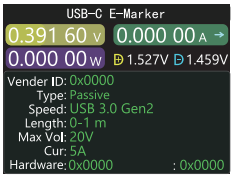
10.0.4 USB-C-E-Marker
E-Marker cable refers to a cable with an E-Marker chip in the Type-C interface,If the interface does not contain E-Marker chip, The packets from the PD charging head cannot exceed 3A current, And only use the E-Marker cable to trigger the PD protocol, The current can exceed 3A.
When using the USB-C electronic label,Except that the Type-C interface cannot be used for power supply,PC port,USB-A,Micro-USB interface can all be used for power supply.The PD communication switch needs to be turned ON.
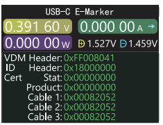
After entering this function,From the output Type-C interface,Plug in the cable,You can read the message,As shown below:
Click the middle button to switch to the figure below:
The two pictures above,The picture shows the parsed data,The second picture is the original data,Users can consult the relevant information of the PD agreement by themselves, Do your.
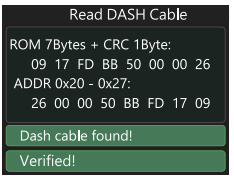
10.0.5 Read DASH cable
Enter this function,Plug in the DASH cable,You can read the chip-related data,As shown below
10.0.6 Soft DASH Cable
This function is used without DASH cable.
The USB-A head of the DASH cable will have one more data pin than the ordinary USB-A data cable.And one more chip,Used to identify and start VOOC/WARP flash charge.
If,The phone normally needs to use a USB-A->Type-C DASH cable,But there is no such thread in hand,Only FNB48 tester and a C-C cable,But want to trigger VOOC/WARP flash charge,At this time, the function of simulating DASH cable can be started,And use the C-C cable to connect to the phone, You can perform VOOC/WARP flash charging.
Note: Since this method does not use the original data cable for charging, The charging power is largely affected by the C-C line,If the impedance of the C -C line is high,Then the charging power will be reduced a lot.
10.0.7 Soft APPLE 2.4A accelerator
When the Apple device detects that the charging head D+ and D- are2.7V,To charge at 5V-2.4A,This function sets D+ and D- to 2.7V.
11. Settings
In the application interface, select the toolbox and press the middle button to enter the toolbox page. The function options are as follows. Select the left and right buttons and press the middle button to enter each function option.
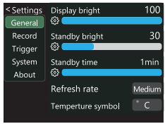
11.0.1 General
Left and right keys to select and press the middle key to enter various function options.
●Display brightness:Set the screen brightness, the adjustable range is 1-100.
●Standby brightness:Set the standby screen brightness,Adjustable range 0-100 level, when set to 0,Enter the standby state and turn off the screen directly.
●Standby time:Set the standby time, the last time you operate the button to start timing,Reach the standby time,Enter the standby state
●Refresh rate: select slow-medium-fast.
●Temperature symbol:The onboard temperature can be displayed as°C/℉.
●Language:Currently only Chinese/English is supported. Due to the character size problem, English will be displayed in the Chinese system, which is abnormal phenomenon.
●Gravity direction recognition:Turn on to automatically rotate the screen.
●Boot page:Turn on/off the boot page.
●Key Tone: Turn on/off the key tone.
11.0.2 Record
Left and right keys to select and press the middle key to enter various function options.
●Curve recording time:Set the recording time of the voltage and current curve, Maximum 9 hours,Set to no time record.Every time you change the configuration,the curve will be cleared to 0.
●Statistical current threshold:When the current ≥ the threshold,To carry out statistics on capacity, energy, and time,Setting range 0-7A.
●Energy statistics time:Set to no time,No time limit,Until the statistics reach the maximum value. After setting the time,When the statistical time reaches the set value, the statistics will automatically stop.
●Clear all records:Clear all recorded data,Including offline curves,Energy statistics.
11.0.3 Trigger
Left and right keys to select and press the middle key to enter various function options.
●Trigger time:Set the time to manually trigger the protocol.
●Monitor mask PD CRC: After opening,When PD is monitoring,CRC messages can be masked,Off by default.
●Boot simulation DASH:After it is turned on, turn on the analog DASH cable function at boot, which is turned off by default
●Boot analog Apple 2.4A accelerator:After opening,Turn on the Apple 2.4A acceleration function when booting,Off by default.
11.0.4 System
Factory reset.
11.0.5 About
Check the version number and other related information.
12. Upgrade firmware instructions
1. Open the host computer software
2. When the meter is off, press the middle button, use the data cable with data transmission to connect to the PC online port, and the computer displays the main page of the host computer software, which means the connection is successful.
3. Click System--Click Folder--Select Firmware.
4. Click the upgrade symbol to start the firmware upgrade. After the upgrade is completed, the meter will automatically restart and enter the main interface.
Production information
Manufacturer: Shenzhen FNIRSI Technology Co., Ltd
Address: 8th Floor, West of Building C, Weihuada Industrial Park, Dalang Street, Longhua District, Shenzhen, Guangdong Province