OWNER’S MANUAL
G-Series Reach-In & Pass Thru
Refrigerator, Freezer & Hot Holding
*For equipment produced after 05-2023 only.
Hours Of Operation: Monday - Friday 7:30 a.m. - 4:30 p.m.
(CST)
4401 Blue Mound Road Fort Worth, Texas 76106 (USA)
Phone: 800.825.8220 | Service Fax: 817.740.6757 | E-mail: [email protected] | Website: traulsen.com
Quality Refrigeration
TABLE OF CONTENTS
1. THE SERIAL TAG
B.a-Ventilated Area Page 6
B.b-Cabling Page 6
B.c-Detection of Flammable Refrigerants Page 6
C-Removal & Evacuation Page 7
D-Spare Parts Page 7
E-Warranty Registration Page 7
7. MICROPROCESSOR CONTROL
A-Control Features Page 7
B-Control Panel Page 8
C-Parts Assembly Page 8
D-Notes To The User Page 9
E-Enter The Customer Password Page 9
F-Enter The Technician Password Page 10
G-Service Parameters Page 11
H-Adjust The Set Point Page 12
I-AdjustTheSetPointDierential Page12
J-Change The Temperature Scale Page 12
K-Set Date & Time Page 13
L-Set Daylight Savings Page 13
M-Start A Defrost Page 14
N-Set Defrost Mode Page 14
O-Set Defrost Schedule Page 14
P-View The Sensor Temperatures Page 15
Q-Hot Food-Unlocking The Keypad Page 16
R-Hot Food-Adjust The Set Point Page 16
S-Hot Food-Change The Temperature Set Point
(Short Cut) Page 16
T-HotFood-TurnTheUnitO Page16
8. SPARE & REPLACEMENT PARTS LISTING Page 17
9. TROUBLESHOOTING GUIDE Page 18
1. THE SERIAL TAG Page 1
2. RECEIPT INSPECTION Page 2
3. INSTALLATION
A-Location Page 2
B-Packaging Page 2
C-Installing Legs or Casters Page 2
D-Shelf Pins Page 3
E-Removing The Doors & Hardware Page 3
F-Cord & Plug Page 3
G-Power Supply Page 3
H-Wiring Diagram Page 3
I-Clearance Page 4
J-Installing Optional Interior Kits Page 4
K-ON/OFF Switch Page 4
4. OPERATION
A-Refrigerators Page 4
B-Freezers Page 4
C-Light Switches Page 5
D-TurnOTemperatureDisplay-MainDisplay
Short Cut Page 5
5. CARE & MAINTENANCE
A-Cleaning The Condenser Page 5
B-Hinge Replacement Page 5
C-Replacing The Gaskets Page 5
D-Cleaning The Exterior Page 6
E-Cleaning The Interior Page 6
F-Adjusting The Shelves Page 6
6. OTHER
A-Service Information Page 6
FORT WORTH, TX. USA
SERIAL MODEL
VOLTS Hz PH
TOTAL CURRENT AMPS
MINIMUM CIRCUIT AMPS
MAXIMUM OVERCURRENT PROTECTION AMPS
LIGHTS WATTS
HEATERS AMPS
REFRIGERANT TYPE OZ
DESIGN PRESSURE HIGH LOW
REFRIGERANT TYPE OZ
DESIGN PRESSURE HIGH LOW
370-60294-00 REV (A)
READING THE SERIAL TAG
• Serial = The permanent ID# of your Traulsen
• Model = The model # of your Traulsen
• Volts = Voltage
• Hz = Cycle
• PH = Phase
• Total Current = Maximum amp draw
• Minimum Circuit = Minimum circuit ampacity
• Lights = Light wattage
• Heaters = Heater amperage (Hot Food units only)
• Refrigerant = Refrigerant type used
• Design Pressure = High & low side operating
pressures and refrigerant charge
• Agency Labels = Designates agency listings
The serial tag is a permanently affixed label upon
which is recorded vital electrical and refrigeration data
about your Traulsen product, as well as the model
and serial number. This tag is located in the upper
right interior compartment on all Traulsen G-Series
refrigerator and freezer models.
G SERIES
Page 1
3. INSTALLATION (cont’d)
during manufacturing, shipping and installation. After the unit
is installed in place of service, remove and discard the covering
from all surfaces. If at all possible we suggest that the cabinet
remain bolted to the pallet during all transportation to the point
of nal installation. To remove the wooden pallet, the bolts
can then be removed with a 3/4” socket wrench. Avoid laying
the unit on its front, side or back for removal of the pallet.
NOTE: DO NOT LAY THE UNIT ON ITS SIDE DURING
TRANSPORTATION OR INSTALLATION.
3C - INSTALLING CASTERS OR LEGS:
A set of four (4) 6” high casters and sixteen (16) bolts are sup-
plied standard for all Traulsen G-Series units. These are shipped
from the factory packed inside a cardboard box which is strapped
inside the cabinet to the lower shelf.
Legs in lieu of casters are available as an optional accessory
kit for the same models. These are shipped inside a separate
cardboard box. Inside it should contain four (4) legs and sixteen
(16) bolts.
WARNING: THE CABINET MUST BE BLOCKED AND STA-
BLE BEFORE INSTALLING LEGS OR CASTERS.
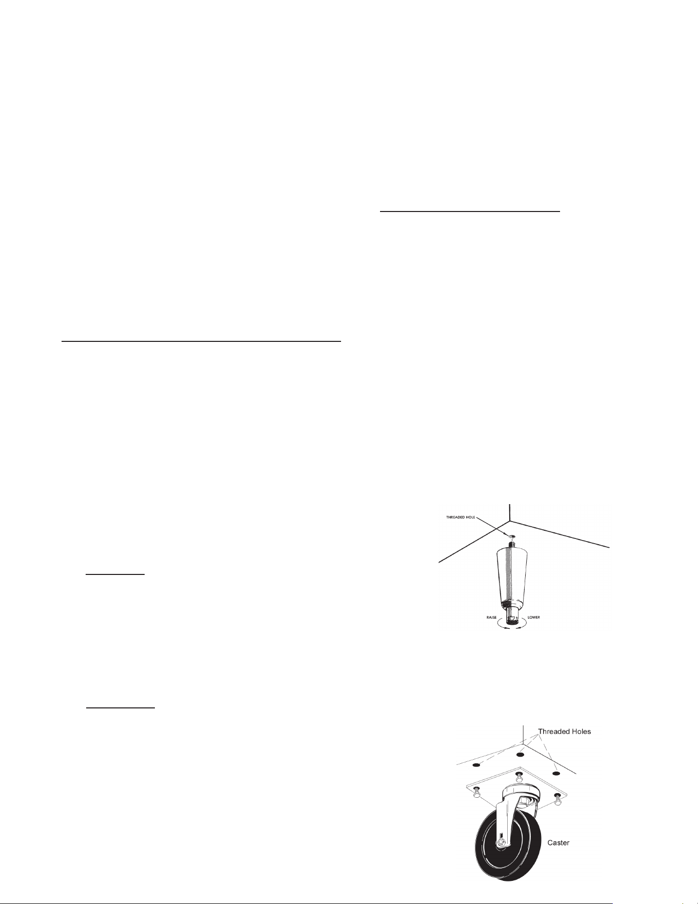
Toinstallthelegsorcasters,rstraiseandblockthereach-ina
minimumof7”fromtheoor.Forinstallinglegs,threadthelegs
intothethreadedholesonthebottomofthecabinet(seegure
1). Be certain that all legs are tightly secured. When the unit
issetinitsnalposition,itisimportantforproperoperationthat
the unit be level. The legs are adjustable for this purpose, turn
the bottom of the leg counterclockwise to raise it, clockwise to
lower it. Level the unit from front to back as well as side to side
in this manner.
Please note that Traulsen units are not designed to be moved
while on legs. If the unit requires moving, a pallet jack or forklift
should be used to prevent damage. For installing casters, the
casters are a “plate” type, and require the use of four (4) bolts
eachtosecurethemrmlytothecabinetbottomateachcorner
(seegure2).Thecasterboltsaretightenedusinga1/2”socket
wrench.
Fig. 2
Fig. 1
2. RECEIPT INSPECTION
All Traulsen products are factory tested for perfor- mance
and are free from defects when shipped. The utmost
care has been taken in crating this product to protect
againstdamageintransit.Allinteriorttingshavebeen
carefully secured and the casters/legs are boxed and
strapped inside to prevent damage. Door keys will be
attached to the handle with a nylon strip. The handle
is protected by an easily removable nylon netting.
You should carefully inspect your Traulsen unit for
damage during delivery. If damage is detected, you
should save all the crating materials and make note on
the carrier’s Bill Of Lading describing this. A freight claim
shouldbeledwithin5days.Ifdamageissubsequently
noted during or immediately after installation, contact
the respective carrier and le a freight claim. Under
no condition may a damaged unit be returned to
Traulsen without rst obtaining written permission
(return authorization). You may contact Traulsen
customer care at (800) 333-7447 to request a return.
SYSTEMS USING REFRIGERANT R-290 (PROPANE)
Traulsen has selected propane as the refrigerant for
many of their products.
In addition to its low global warming potential and impact
on the environment, propane is an ideal refrigerant. It is
aammablerefrigerant,however,whichiswhyyouwill
seea“ammablerefrigerant”stickerapplicableproducts.
Traulsen products using propane as the refrigerant are
UL approved and are safe to use in accordance with
this Owner’s Manual and general industry practices for
commercial cooking environments.
Please check with local codes or regulations for any
restrictions to products using hydrocarbon refrigerants.
3. INSTALLATION
3A - LOCATION:
Select a proper location for your Traulsen unit, away
from extreme heat and allow proper clearance for
air circulation (see page 4). Allow enough clearance
between the unit and the side wall in order to make
use of the door stay open feature at 120° (self-
closing feature operates up to 90°). The door(s)
must be able to open a minimum of 90° in order to
make use of the maximum clear door width available.
3B - PACKAGING:
All Traulsen units are shipped from the factory bolted
to a sturdy wooden pallet and packaged in a durable
Styrofoam backed cardboard wrap.
Most exterior stainless steel and aluminum surfaces
have a protective vinyl covering to prevent scratching
G SERIES
Page 2
3D - SHELF PINS:
The unit is supplied with shelves and shelf pins installed. Check
all shelf pins to assure they are tightened down as they may have
come loose during shipping. Rotate the pins clockwise until they
are secured against the side of the cabinet.
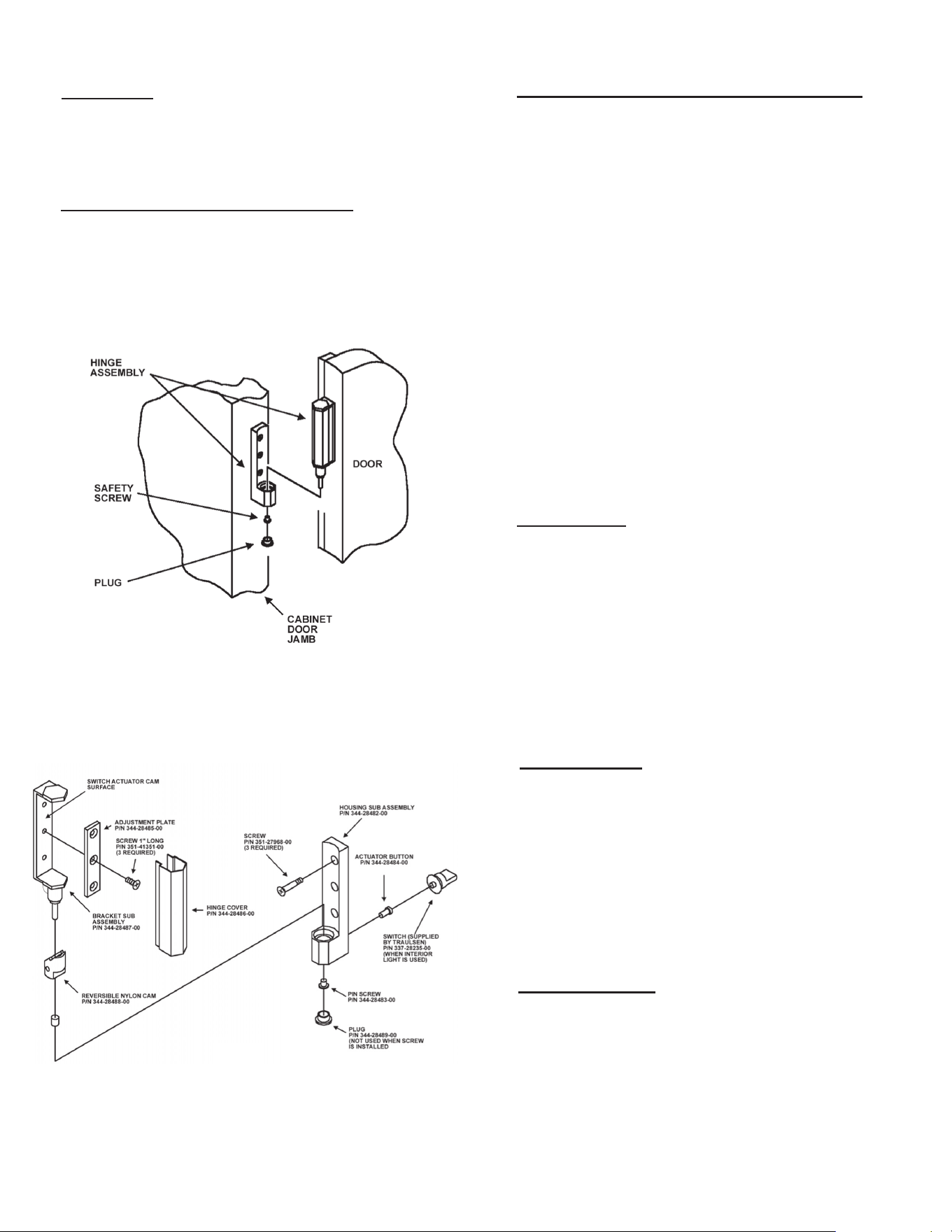
3E - REMOVING THE DOORS & HARDWARE:
Inordertotthroughnarrow(lessthan35”)doorways,itmaybe
necessary to remove the door(s), and/or hinges. To remove any
solid door, begin by removing the plug at the bottom of the top
hinge. Inside the hinge there is a small screw which secures the
doorinplace.Removethiswithaatheadscrewdriverandthe
doorcanthenbeliftedothehinges(seegure3).
After removing the door, it maybe necessary to remove the hinge
assembly and hardware from the door itself.
3. INSTALLATION (cont’d)
3E - REMOVING THE DOORS & HARDWARE
(cont’d)
:
If it is necessary to remove the hinge hardware from the
cabinet, begin by removing the three Phillips head screws
which hold it in place. Set these components aside for
later reassembly. Pay special attention not to loose the
door switch actuator button controls evaporator fan and
interiorlightoperation(seegure4).
NOTE: All solid door units include a microswitch for
controlling the interior lighting in the top hinge(s).
Special care should be taken to not damage the wiring
for this during the hinge removal process.
The lock keeper may also require removal in order to
reduce the overall cabinet depth to 32”.
Next remove the lock keeper bracket by removing the two
(2)atheadscrewswhichsecureitinplace.Setthese
components aside for later reassembly.
To re-install the door and/or hinges, please reverse the
appropriate sections of the preceding procedure.
3F - CORD & PLUG:
All G-Series models are supplied with a cord & plug
attached. It is shipped coiled at the top of the cabinet,
secured by a nylon strip. For your safety and protection,
all units supplied with a cord and plug include a special
three-prong grounding plug on the service cord. Select
only a dedicated electrical outlet with grounding plug for
power source.
NOTE: Do not under any circumstances, cut or re-
move the round grounding prong from the plug, or
use an extension cord.
3G - POWER SUPPLY:
The supply voltage should be checked prior to connection
to be certain that proper voltage for the cabinet wiring is
available (refer to the serial tag to determine correct unit
voltage). Make connections in accordance with local
electricalcodes.Usequaliedelectricians.
Use of a separate, dedicated circuit is required. Size wir-
ing to handle indicated load and provide necessary over
current protector in circuit (see amperage requirements
on the unit’s serial tag).
3H - WIRING DIAGRAM:
Refer to the wiring diagram located on the exterior back
of the cabinet for any service work performed on the
unit. Should you require one, please contact Traulsen
Service at (800) 825-8220, and provide the model and
serial number of the unit involved.
Fig. 3
Fig. 4
G SERIES
Page 3
4B - FREEZERS:
During normal operation, a freezer continuously circulates below
freezing cabinet air through the evaporator coil. The coil requires
a periodic defrosting for proper operation. This is accomplished
by an automatic, time activated, temperature/time terminated,
defrost program. The controller is preset at the factory for six
equally spaced defrost cycles within each 24-hour period.
The evaporator fan(s) cycle o with each door opening. The
evaporatorfan(s)willcycleon(15seconds)ando(45seconds)
duringthecompressorocycle.Duringthecompressoroncycle
the evaporator fan(s) will run continuously.
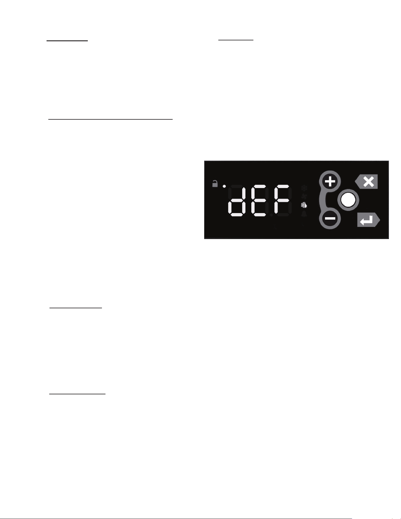
At the start of a refrigerator or freezer defrost cycle, both the com-
pressorandevaporatorfansareo.Themicroprocessorcontrol
willread“dEF”(seegure5).
The electric heater (attached to the coil) is energized. When the
temperature sensor axed to the coil senses 45°F, the coil is
fully defrosted and the compressor operation is resumed, defrost
heatersareautomaticallyturnedo.Theevaporatorcoilfansare
delayed from starting at the termination of a defrost cycle. Fan
operation is automatically resumed, after a short time or temp
delay(whichevercomesrst).Aftercompletion,thetotalrefrigera-
tion system operation is then resumed. During defrost operation,
heatisconnedtothecoilenclosuretopreventanysignicant
rise in temperature within the food zone. The fan delay control
function upon termination of a defrost cycle is two-fold. First, to
prevent blowing warm air into the food storage area. Second, to
prevent any condensation on the defrost coil from being blown
into the food storage area.
The microprocessor control is set from the factory to terminate
defrost at 25 minutes for refrigerators and 30 minutes for freez-
ers in the event of a sensor failure. This setting should never be
tamperedwith,withoutrstconsultingthefactory.
4A - REFRIGERATORS:
Both refrigerators and freezers do not require manual
defrosting. During normal operation, a refrigerator con-
tinuously circulates above freezing cabinet air through the
evaporator coil. An electric defrost occurs every 8 hours
for a maximum length of 25 minutes to melt any frost which
may accumulate on the coil during the compressor “ON”
cycle. With standard holding refrigerators, high relative
humidity is also maintained to prevent dehydration of
stored product.
3I - CLEARANCE:
In order to assure optimum performance, the condensing
unit of your Traulsen unit MUST have an adequate sup-
ply of air for cooling purposes. Therefore, the operating
location must either have a minimum of 12” clearance
overhead of the condensing unit or allow for unrestricted
airowatthebackoftheunit.Clearanceofatleast12”
above is required in order to perform certain maintenance
tasks.
3J - INSTALLING OPTIONAL INTERIOR KITS:
In addition to their standard interiors, G-Series models
alsooertheoptionforadditionalshelvesortrayslides.
If ordered, these are shipped as kits along with the unit,
packaged in a separate cardboard box which contains all
the necessary parts and hardware for on-site installation.
Toinstalladditionalshelves,rstremovethewhiteplastic
covers from inside the cabinet. These are located along
the same vertical line as the pins already in place on the
interior side walls, back and center mullion (two and three-
section models). This exposes threaded holes in which
you may position the new shelves. Next insert the gray
plastic shelf pins into these holes and tighten by turning
clockwisewithyourngers.Afterallfourpinsareinplace,
the new shelf should be placed to rest on top of them.
The unused plastic covers may be discarded or saved
for future changes to the cabinet interior.
Installation of optional tray slides varies with each cabi-
net, and with each type of tray slide ordered. To install
optional tray slides, follow the directions packaged inside
the kit carton.
3K - ON/OFF SWITCH:
An ON/OFF toggle switch for the power supply is pro-
vided. It is located on top of the unit, mounted to the
side of the evaporator housing. This is shipped from the
factory in the ON position.
3. INSTALLATION (cont’d)
4. OPERATION
4. OPERATION (cont’d)
Fig. 5
G SERIES
Page 4
5A - CLEANING THE CONDENSER (cont’d):
Vacuum or brush any dirt, lint or dust from the nned
condenser coil, the compressor and other cooling system
parts. If signicant dirt is clogging the condenser ns,
use compressed air to blow this clear. Care should be
takennottobendanyofthecondenserns,asthiswill
reduce performance and compressor life. Lower louver
assembly and replace screws to hold it in place.
SYSTEMS USING REFRIGERANT R-290 (PROPANE)
Remove any ignition source (arc, ame, heat) before
cleaning the condenser coil. If the condenser coil is
inadvertently damaged during cleaning to the point of
causing a refrigerant leak, immediately ventilate the area
and call for service.
5B - HINGE REPLACEMENT:
To remove the door, remove the plug at the bottom of the
top hinge. Behind this is a screw which secures the door
inplace.Removethiswithaatheadscrewdriverand
thenliftthedoorothehinge.Toremovethedoorportion
ofthehinge,liftothehingecoverandthenremovethe
3 Phillips head screws which secure the hinge in place.
To remove the cabinet portion of the hinge, remove the 3
Phillips head screws which hold it in place. On solid door
units, the top hinge(s) contains a switch for controlling the
lights.To reassemble the hinge reverse the procedure.
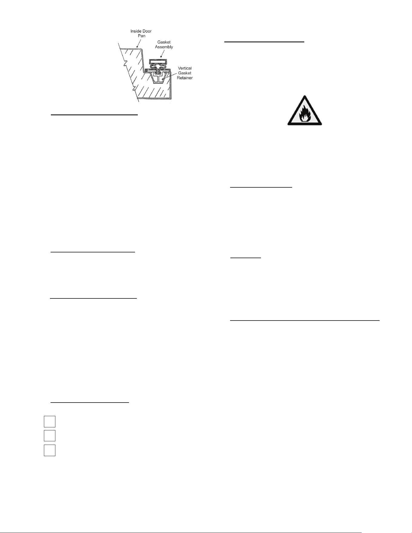
5C - REPLACING THE GASKETS:
Toremovethegaskettobereplaced,graspitrmlyby
one corner and pull it out. Before attempting to install a
new gasket, both the unit and gasket must be at room
temperature.Insertthefourcornersrstbyusingarub-
ber mallet (or hammer with a block of wood). After the
corners are properly inserted, work your way towards the
center from both ends by gently hitting with a mallet until
thegasketiscompletelyseatedinplace(seegure7for
proper gasket placement).
4C - LIGHT SWITCHES:
All G-Series models include a concealed door switch mounted in
the top door hinge(s), which automatically activates the interior
light when the door is opened. When the door is closed, the lights
are not operating.
In addition, on hinged glass door models, an exterior mounted,
illuminated red switch is included for manual light control. In the
ON position, the lights are illuminated whether the doors are open
or not. In the OFF position, the lights are controlled by the hinge
switchasdescribedintherstparagraph.’
4D - TURN OFF TEMPERATURE DISPLAY-MAIN DISPLAY
SHORT CUT: There is a short cut to disable the external tempera-
ture display. Note that before doing so you must install an interior
mounted thermometer in order to conform with local health codes.
• Press the Unlock Key twice
within a second in order to unlock
the keypad (think “tap-tap”).
• The Keypad Unlock LED will
turn on to indicate the keypad
is now live.
• Press and hold the Unlock Key for 3 seconds until the
temperature display goes blank.
To restore the temperature display, press any key except the
Unlock Key:
• Press the Unlock Key twice within a second in order to unlock
the keypad (think “tap-tap”).
• The Keypad Unlock LED will turn on to indicate the keypad is
now live.
• Press any key except the Unlock Key to restore the
temperature display.
5. CARE & MAINTENANCE
WARNING: DISCONNECT ELECTRICAL POWER SUPPLY
BEFORE CLEANING ANY PARTS OF THE UNIT.
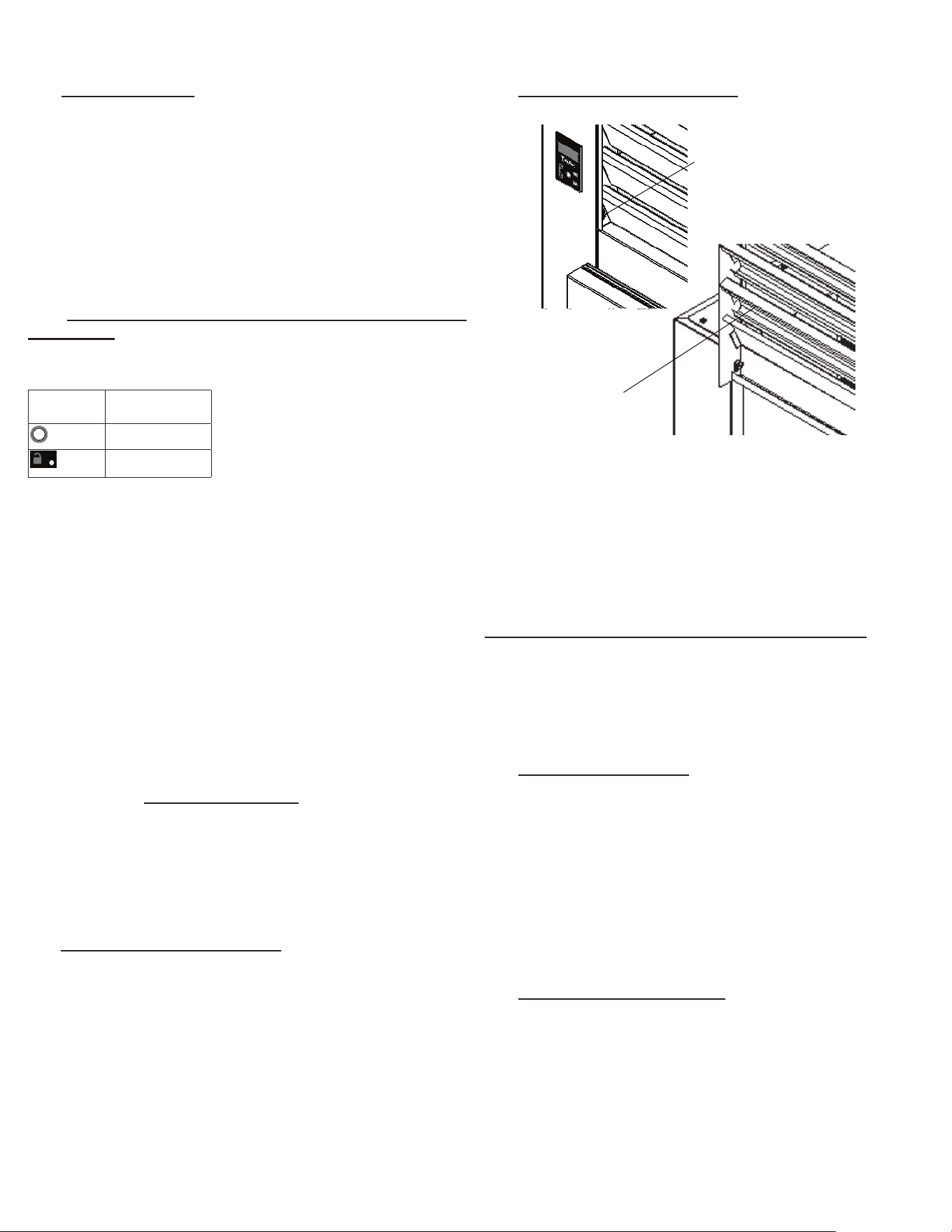
5A - CLEANING THE CONDENSER:
The most important thing you can do to insure a long, reliable ser-
vice life for your Traulsen is to regularly clean the condenser coil.
The condensing unit requires regularly scheduled cleaning to
keepthennedcondensercleanoflintanddustaccumulation.
Keeping the condenser clean allows the cabinet to operate more
eciently anduse less energy. To cleanthecondenser, rst
disconnect electrical power to the cabinet and lift up the front
louver assembly. To lift this, remove the two screws located on
bothsidesatthebottomofthelouverassembly(seegure5).
Once the screws are removed, the panel can be pivoted upwards
allowingfullaccesstothefrontfacingcondenser(seegure6).
5. CARE & MAINTENANCE (cont’d)
4. OPERATION (cont’d)
Fig. 6
Lift-Up Louver
Assembly
Fig. 5
Remove
Screws
G SERIES
Page 5
DISPLAY
SYMBOL
DISPLAY
DESCRIPTION
Unlock Key
Keypad Unlock
LED
5D - CLEANING THE EXTERIOR:
Exterior stainless steel and aluminum should be cleaned
with warm water, mild soap and a soft cloth. Apply with
a dampened cloth and wipe in the direction of the metal
grain.
Avoid the use of strong detergents and gritty, abrasive
cleaners as they may tend to mar and scratch the surface.
Do NOT use cleansers containing chlorine, this may
promote corrosion of the stainless steel.
Care should also be taken to avoid splashing the unit with
water, containing chlorinated cleansers, when mopping
theooraroundtheunit.
For stubborn odor spills, use baking soda and water
(mixed to a 1 TBSP baking soda to 1 pint water ratio).
5E - CLEANING THE INTERIOR:
For cleaning anodized aluminum interiors, the use of bak-
ing soda as described in section “V. d” is recommended.
Use on breaker strips as well as door gaskets. All interior
ttingsareremovablewithouttoolstofacilitatecleaning.
5F - ADJUSTING THE SHELVES:
For shelves mounted on pins, rst select the desired
location and remove the white plastic covers in the inte-
rior back and sides by rotating them counterclockwise.
Remove the shelf pins by rotating them counterclockwise.
Install the pins in the desired location by rotating clock-
wise. Make sure the pin is securely tightened down. Do
not over tighten. Slide the shelf into its new position, and
replace the white plastic covers into the holes vacated
by the shelf pins.
6. OTHER
6A - SERVICE INFORMATION:
Before calling for service, please check the following:
Is the electrical cord plugged in?
Is the fuse OK or circuit breaker on?
Is the power switch “ON”?
If after checking the above items and the unit is still
not operating properly, please contact an authorized
Traulsen service agent. You may obtain the name of a
service agent from the Service tab of our website: www.
traulsen.com.
6A - SERVICE INFORMATION (cont’d):
If service is not satisfactory, please contact our in-house service
department at: Traulsen
4401 Blue Mound Road Fort Worth, TX 76106
(800) 825-8220
Traulsenreservestherighttochangespecicationsordiscontinue
models without notice.
Fig. 7
5. CARE & MAINTENANCE (cont’d) 6. OTHER (cont’d)
NOTE: The gasket may
appear too large, but if it
is installed as indicated
above it will slip into
place.
G SERIES
Page 6
This appliance is marked with the ISO 7010-W021
warning label to indicate the presence of FLAMMABLE
REFRIGERANTS. Prior to beginning work on systems
containing FLAMMABLE REFRIGERANTS, safety checks are
necessary to ensure that the risk of ignition is minimized.
6B.a - VENTILATED AREA
Ensure that the area is in the open or that it is adequately
ventilated before breaking into the system or conducting any
hot work. A degree of ventilation shall continue during the
period that the work is carried out. The ventilation should
safely disperse any released refrigerant and preferably expel it
externally into the atmosphere.
6B.b - CABLING
Check that cabling will not be subject to wear, corrosion, exces-
sive pressure, vibration, sharp edges, or any other adverse
environmentaleects.Thecheckshallalsotakeintoaccount
theeectsofagingorcontinualvibrationfromsourcessuchas
compressors or fans.
6B.c - DETECTION OF FLAMMABLE REFRIGERANTS
Under no circumstances shall potential sources of ignition be
used in the searching for or detection of refrigerant leaks. A
halidetorch(oranyotherdetectorusinganakedame)shall
not be used.
The following leak detection methods are deemed acceptable
for all refrigerant systems. Electronic leak detectors may
be used to detect refrigerant leaks but, in the case of
FLAMMABLE REFRIGERANTS, the sensitivity might not be
adequate, or might need recalibration. (Detection equipment
shall be calibrated in a refrigerant-free area.) Ensure that the
detector is not a potential source of ignition and is suitable for
the refrigerant used. Leak detection equipment shall be set at a
percentage of the LFL of the refrigerant and shall be calibrated
to the refrigerant employed, and the appropriate percentage of
gas(25%maximum)isconrmed.
Leakdetectionuidsarealsosuitableforusewithmost
refrigerants but the use of detergents containing chlorine shall
be avoided as the chlorine can react with the refrigerant and
corrode the copper pipe-work.
6. OTHER (cont’d)
6B.c - DETECTION OF FLAMMABLE REFRIGERANTS
(cont’d)
NOTE:Examplesofleakdetectionuidsare
- bubble method
-uorescentmethodagents
Ifaleakissuspected,allnakedamesshallberemoved/
extinguished.
If a leakage of refrigerant is found which requires brazing,
all of the refrigerant shall be recovered from the system,
orisolated(bymeansofshutovalves)inapartofthe
system remote from the leak. Removal of refrigerant shall
be according to Section 6C below.
6C - REMOVAL & EVACUATION
When breaking into the refrigerant circuit to make repairs-
or for any other purpose - conventional procedures shall
beused.However,forammablerefrigerantsitisimportant
thatbestpracticebefollowed,sinceammabilityisa
consideration. The following procedure shall be adhered to:
a) safely remove refrigerant following local and national
regulations;
b) purge the circuit with inert gas;
c) evacuate
d) purge with inert gas;
e) open the circuit by cutting or brazing.
The refrigerant charge shall be recovered into the correct
recovery cylinders if venting is not allowed by local and
nationalcodes.Forappliancescontainingammable
refrigerants, the system shall be purged with oxygen-
freenitrogentorendertheappliancesafeforammable
refrigerants. This process might need to be repeated
several times. Compressed air or oxygen shall not be used
for purging refrigerant systems.
Forappliancescontainingammablerefrigerants,
refrigerants purging shall be achieved by breaking the
vacuum in the system with oxygen-free nitrogen and
continuingtolluntiltheworkingpressureisachieved,
thenventingtoatmosphere,andnallypullingdowntoa
vacuum. This process shall be repeated until no refrigerant
iswithinthesystem(optionalforA2L).Whenthenal
oxygen-free nitrogen charge is used, the system shall be
vented down to atmospheric pressure to enable work to
take place.
Ensure that the outlet for the vacuum pump is not close
to any potential ignition sources and that ventilation is
available.
6D - SPARE PARTS:
Spare or replacement parts may be obtained through a parts
supplier or one of our authorized service agents (see page
17-18 for parts listing). A list of authorized service agents is
postedonourcompany’socialwebsiteServicetabatwww.
traulsen.com.
6E - WARRANTY REGISTRATION:
The warranty for your new Traulsen unit may be registered
with us by completing warranty information online, via our
website www.traulsen.com click on Service Tab or calling us
direct at 800-825-8220.
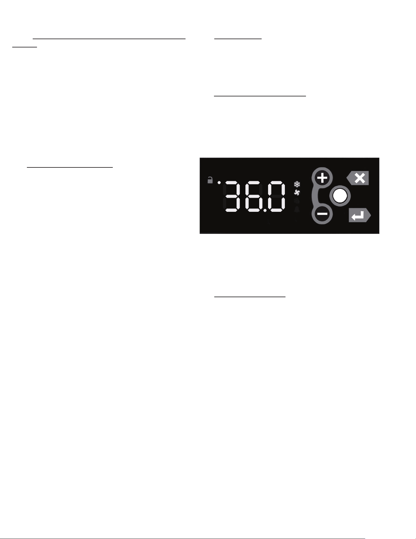
7. MICROPROCESSOR CONTROL
Your new Traulsen G-Series Refrigerator, Freezer or Hot
Food is equipped with an electronic microprocessor control,
which precisely regulates operation. It is supplied from the
factory completely ready for use. See pages 6 thru 14 for
more information.
7A - CONTROL FEATURES:
Internal Time Clock
• Eliminates defrost time clock (refrigerator and freezer
models only).
• See “Setting The 24-Hour Clock” on Page 11. (Also required
at “Start Up”)
Parameter/Service Levels
• See “Customer/Service Parameters” on Page 8 - 9.
Defrost - See “Setting Defrost” on page 12
•Customerscansetupto6dierentdefrostschedules.The
defrost schedule allows the customer to decide when defrosts
will take, preventing a defrost cycle during peak kitchen use.
NOTE: The 24-hour clock must be set for this feature to
operate correctly.
G SERIES
Page 7
7. MICROPROCESSOR CONTROL (cont’d)
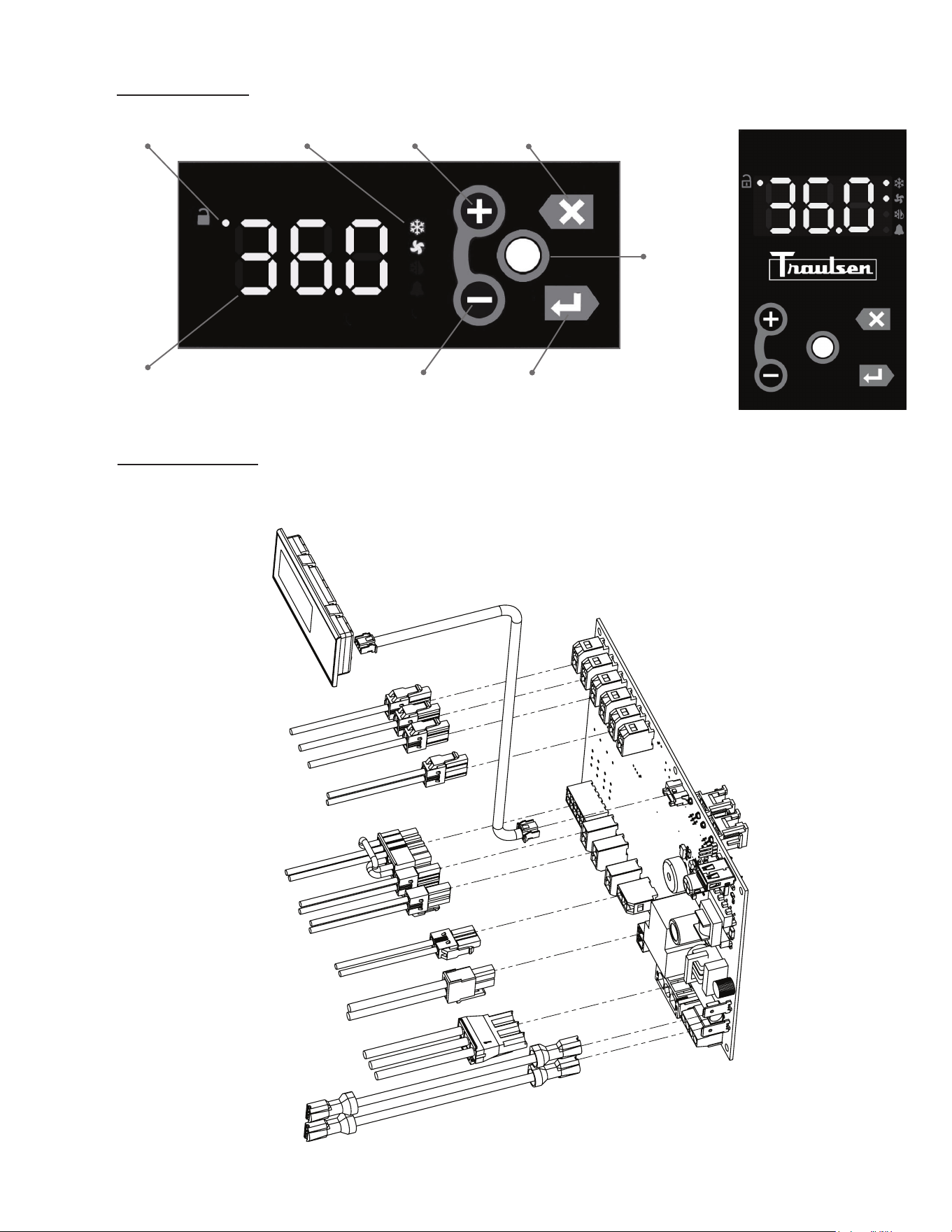
7B - CONTROL PANEL:
7C - PARTS ASSEMBLY:
NOTE: Parts can be ordered separately by calling Traulsen at 800-825-8220. Requires unit model and serial to
place order. Please contact factory direct for hot food control drawing if required.
Unlock Symbol Status Icons + or Next Key Esc or Back Key
Cabinet Temp
- or Previous Key
Display or Enter
Key
Unlock or
Modify
Key
PN: 000-90000-XX REV: A
NEXT GEN CONTROL - G
CONTROL BOARD
950-60509-00
CONTROL CABLE
333-60523-00
CONTROL DISPLAY
950-60510-00
BLACK - SWITCH
GREEN - GROUND
BLACK - LINE
WHITE - NEUTRAL
BLUE/WHITE - COMPRESSOR
ORANGE/WHITE - DOOR HEATERS
GRAY/WHITE - EVAPORATOR FANS
PURPLE/WHITE - DEFROST
BLACK/YELLOW - DOOR SWITCH
YELLOW - LIQUID LINE
GREEN - CABINET
YELLOW/WHITE - LIGHTS
BLUE - COIL
BLACK - SWITCH
(Display can be
horizontal or vertical)
G SERIES
Page 8
7. MICROPROCESSOR CONTROL (cont’d)
7D - NOTES TO THE USER:
You only have 3 minutes between button pushes. If you take longer than 3 minutes, the keypad
will lock. The Menu System has a 10 minute timeout. After 10 minutes of inactivity, the controller
will revert back to displaying the cabinet temperature. You can exit the Menu System at any time
by pressing the Esc Key until the cabinet temperature is displayed. If you are making changes
and the keypad locks, press the Unlock Key twice within a second in order to unlock the keypad
(think “tap-tap”).
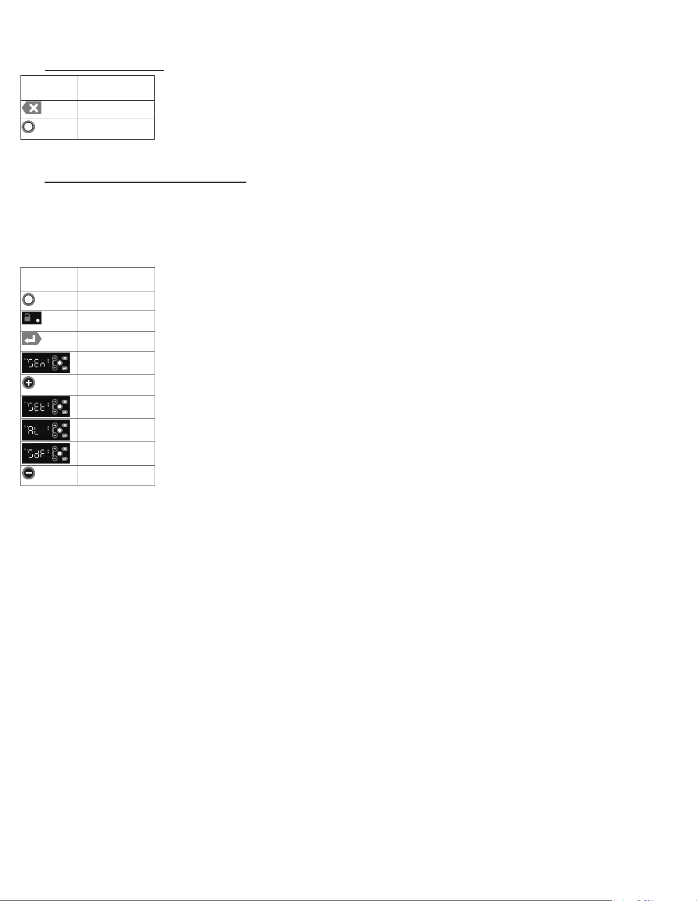
7E - ENTER THE CUSTOMER PASSWORD:
Inordertoaccessthemenusystem,theusermustenterapasswordrst.Oncethepasswordisentered,itremainsineect
until the user returns to the Main Display (the cabinet temperature). If the user does not exit the menu system, the controller
will time-out after 10 minutes of inactivity. The keypad must be unlocked to access the menu system.
• Press the Unlock Key twice within a second in order to unlock the keypad (think “tap-tap”)
• The Keypad Unlock LED will turn on to indicate the keypad is now live
• To enter the Menu System, press the Enter Key
• The display will show “SEn”
• Press the Plus Key to scroll through the menu system. The choices are:
o “SEn” for the Sensors submenu
o “SEt” for the Settings submenu
o “AL” for the Alarm submenu
o “SdF” to start a defrost
• Enter Key to select the desired submenu
•Thedisplaywillshow“000”.Therst“0”willash.
• Use the Plus Key or the Minus Keytomodifytheashingdigituntilitreads“1”.
• Press the Enter Key to accept the value
• Repeat for the 2nd and 3rd digits until the displays shows “111”.
• Press the Enter Key to enter the desired submenu.
DISPLAY
SYMBOL
DISPLAY
DESCRIPTION
ESC Key
Unlock Key
DISPLAY
SYMBOL
DISPLAY
DESCRIPTION
Unlock Key
Keypad Unlock
LED
Enter Key
SEn
Plus (+)
/Next Key
SEt/Settings
AL
SdF
Minus (-)
/Previous Key
G SERIES
Page 9
7. MICROPROCESSOR CONTROL (cont’d)
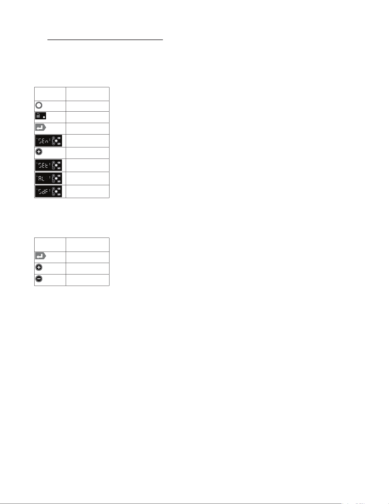
7F - ENTER THE TECHNICIAN PASSWORD:
Inordertoaccessthemenusystem,theusermustenterapasswordrst.Oncethepasswordisentered,itremainsineect
until the user returns to the Main Display (the cabinet temperature). If the user does not exit the menu system, the controller
will time-out after 10 minutes of inactivity. The keypad must be unlocked to access the menu system.
• Press the Unlock Key twice within a second in order to unlock the keypad (think “tap-tap”).
• The Keypad Unlock LED will turn on to indicate the keypad is now live.
• To enter the Menu System, press the Enter Key.
• The display will show “SEn”.
• Press the Plus Key to scroll through the menu system. The choices are:
o “SEn” for the Sensors submenu
o “SEt” for the Settings submenu
o “AL” for the Alarm submenu
o “SdF” to start a defrost
• Enter Key to select the desired submenu.
•Thedisplaywillshow“000”.Therst“0”willash.
• Use the Plus Key or the Minus Keytomodifytheashingdigituntilitreads“5”.
• Press the Enter Key to accept the value
• Repeat for the 2nd and 3rd digits until the displays shows “555”.
• Press the Enter Key to enter the desired submenu.
DISPLAY
SYMBOL
DISPLAY
DESCRIPTION
Unlock Key
Keypad Unlock
LED
Enter Key
SEn
Plus (+)
/Next Key
SEt
AL
SdF
DISPLAY
SYMBOL
DISPLAY
DESCRIPTION
Enter Key
Plus (+)
/Next Key
Minus (-)
/Previous Key
G SERIES
Page 10
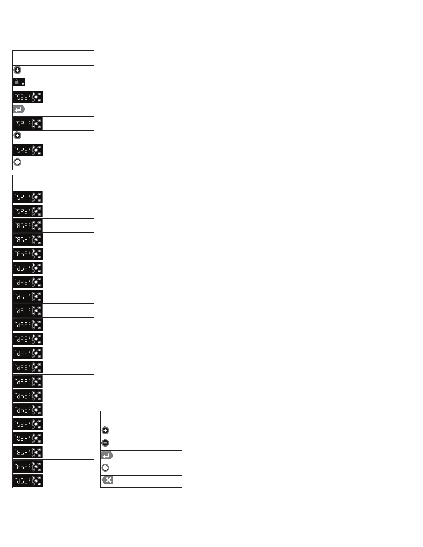
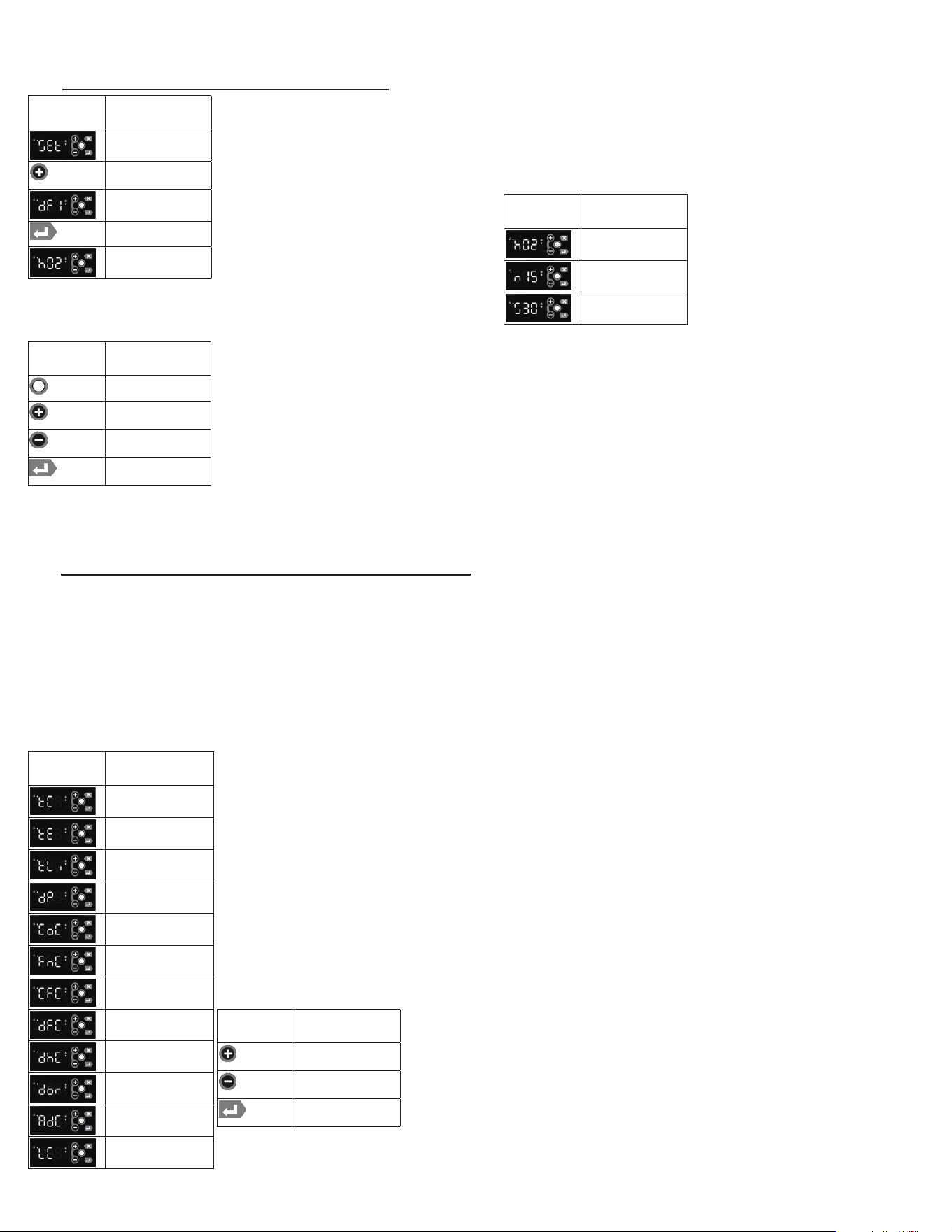
7G - SERVICE PARAMETERS-MENU SYSTEM:
7. MICROPROCESSOR CONTROL (cont’d)
Listed below are the available parameters in the order they appear, use the Plus Key on the
controller to sequence through menu system. The Keypad must be Unlocked to access the
menu system.
• Follow the instructions to enter the technician password (see page 9).
• Use the Plus Key to move to the Settings submenu.
• Press the Enter Key to enter the Settings submenu.
•TherstparameterdisplayedwillbetheSet Point parameter is displayed.
• Press the Enter Key to display the value of the Set Point.
• Use the Plus Key to move to the next parameter (Set Point Dierential).
• Press the Enter Key to display the value of the Set Point Dierential.
• Press the Modify Keytochangeasetting.Thevaluewillash,indicating
itisbeingmodied.
• Use the Plus Key to move through the settings parameters.
The following parameters are available:
o Cabinet Set Point
oSetPointDierential
o Aux Device Set Point
oAuxDeviceSetPointDierential
o Cabinet Fan Door Action
o Defrost Set Point
o Defrost Mode
o Defrost Interval
o Defrost Time1
o Defrost Time2
o Defrost Time3
o Defrost Time4
o Defrost Time5
o Defrost Time6
o Door Heater Mode
o Door Heater Delay
o Serial Number
o Software Version
o Temp Units
o Time Zone
o Daylight Savings Flag
In General:
• Use the Plus Key and the Minus Key to move through the Menu System.
• Press the Enter Key to display the value of the selected parameter.
• Press the Modify Key to change a setting. The value will
ash,indicatingitisbeingmodied.
•Oncethevalueisashing,usethePlus Key and the Minus
Key to change the setting.
• When the display shows the desired setting, press the Enter
Key to accept the value.
• Press the Esc Key to abort an edit operation.
DISPLAY
SYMBOL
DISPLAY
DESCRIPTION
Plus (+)
/Next Key
Keypad Unlock
SEt/Settings
Enter Key
Set Point
Plus (+)
/Next Key
Set Point
Dierential
Modify Key
DISPLAY
SYMBOL
DISPLAY
DESCRIPTION
Set Point
Set Point
Dierential
Aux Device Set
Point
Aux Device Set
PointDierential
Cabinet Fan Door
Action
Defrost Set Point
Defrost Mode
Defrost Interval
Defrost Time1
Defrost Time2
Defrost Time3
Defrost Time4
Defrost Time5
Defrost Time6
Door Heater Mode
Door Heater
Delay
Serial Number
Software Version
Temp Units
Time Zone
Daylight Savings
Flag
DISPLAY
SYMBOL
DISPLAY
DESCRIPTION
Plus (+)
/Next Key
Minus (-)
/Previous Key
Enter Key
Modify Key
Esc Key
G SERIES
Page 11
7. MICROPROCESSOR CONTROL (cont’d)
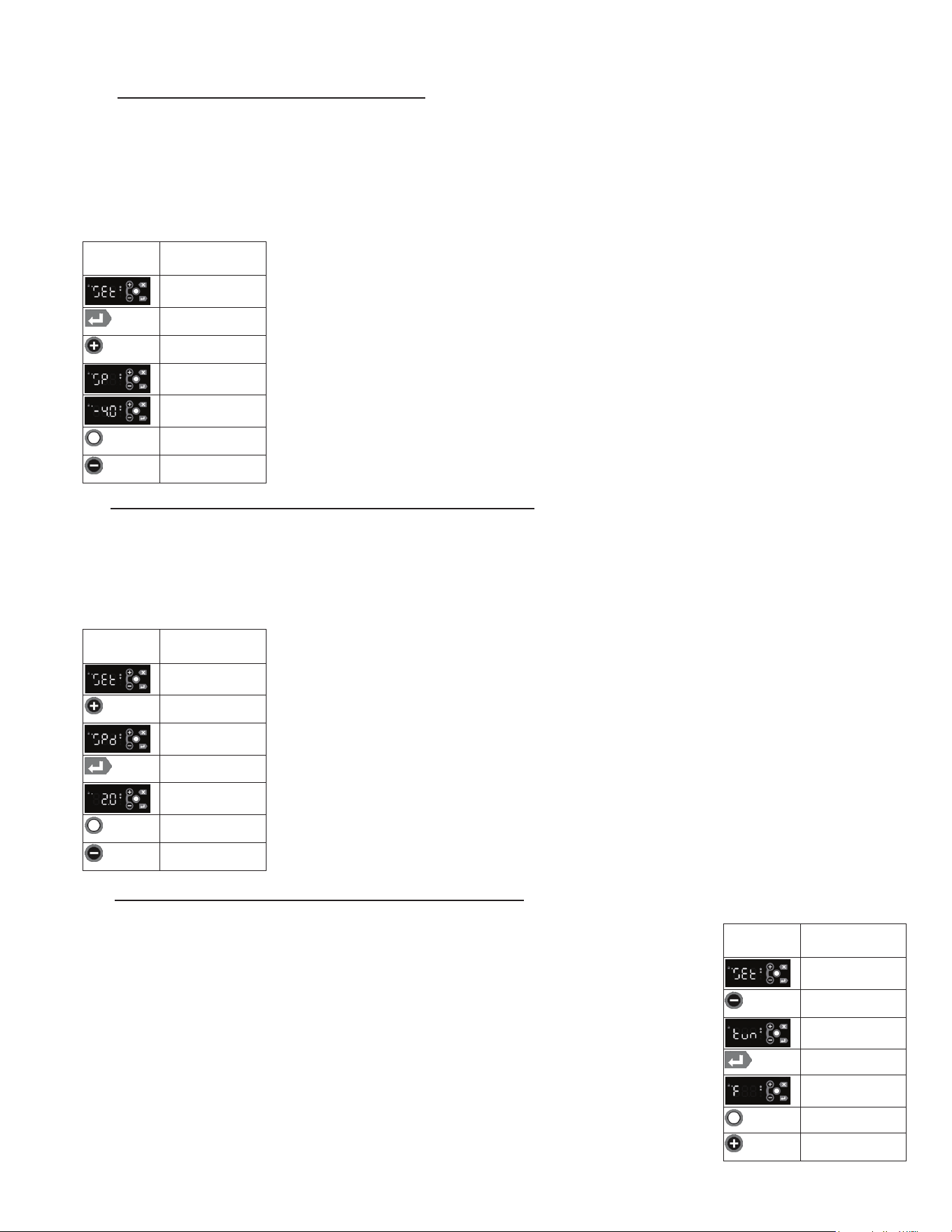
7H - ADJUST THE SETPOINT - MENU SYSTEM:
Thisparametersetsthelowpointofthedesiredcabinettemperaturerange.ThesetpointcanbeconguredfromtheMain
Display using the short cut (see section 75), or from the Menu System.
Typically, freezers will range from -3° F to 0° F (-19° C to -18° C) and refrigerators will range from 35° F to 38° F (2° C to
4° C) for this parameter setting. This parameter is preset at the factory and does not require adjustment unless the cus-
tomer chooses to do so. The setpoint for the unit can be changed from the Menu System. There will be a minimum and
maximum value allowed for the set point. The keypad must be unlocked to access the menu system.
• Follow the instructions to enter the customer password and Settings submenu.
• Press the Enter Key to enter the Settings submenu.
• Use the Plus Key until the Setpoint parameter is displayed
• Press the Enter Key to display the value of the setpoint.
• Press the Modify Keyandthevaluewillash,indicatingitisbeingmodied
• To raise the setpoint, press the Plus Key to increment to the set point.
Press the Minus Key to lower the setpoint.
• When the desired value is reached, press the Enter Key to lock in the value.
7I - ADJUST THE SETPOINT DIFFERENTIAL - MENU SYSTEM:
This parameter sets the number of degrees the air temp will rise above set point before the refrigeration system will cycle
on.Thesetpointdierentialissetat2forbothrefrigeratorandfreezermodelswhichwillallowtheairtemperaturetorise
2 degrees above SP (set point) setting before cycling refrigeration on. This parameter is preset at the factory and does not
requireadjustmentunlessthecustomerchoosestodoso.ThesetpointdierentialcanbechangedfromtheMenuSys-
tem.Therewillbeaminimumandmaximumvalueallowedforthesetpointdierential.Thekeypadmustbeunlockedto
access the menu system.
• Follow the instructions to enter the technician password and Settings submenu.
• Use the Plus Key until the Setpoint Dierent parameter is displayed
• Press the Enter Key to display the value of the set point 2.0.
• Press the Modify Keyandthevaluewillash,indicatingitisbeingmodied
•Toraisethesetpointdierential,pressthePlus Key to increment to the set point
dierential.PresstheMinus Keytolowerthesetpointdierential.
• When the desired value is reached, press the Enter Key to lock in the value.
7J - CHANGE THE TEMPERATURE SCALE - MENU SYSTEM:
The temperature scale determines if the temperature displayed will be in degrees Fahrenheit or degrees Celsius.
The keypad must be unlocked to access the menu system.
• Follow the instructions to enter the technician password and Settings submenu.
• Use the Minus Key until the Temperature Units parameter is displayed.
• Press the Enter Key to display the value of the temperature units.
• Press the Modify Keyandthevaluewillash,indicatingitisbeingmodied.
• To change the temperature units, press the Plus Key to step through the list of choices:
Fahrenheit or Celsius.
• When the desired setting is reached, press the Enter Key to lock in the value.
DISPLAY
SYMBOL
DISPLAY
DESCRIPTION
SEt/Settings
Enter Key
Plus (+)
/Next Key
Set Point
Value Of Set Point
Modify Key
Minus (-)
/Previous Key
DISPLAY
SYMBOL
DISPLAY
DESCRIPTION
SEt/Settings
Plus (+)
/Next Key
Set Point
Dierential
Enter Key
2.O Set Point
Value
Modify Key
Minus (-)
/Previous Key
DISPLAY
SYMBOL
DISPLAY
DESCRIPTION
SEt/Settings
Minus (-)
/Previous Key
Temp Units
Enter Key
Value Of
Temp Units
Modify Key
Plus (+)
/Next Key
G SERIES
Page 12
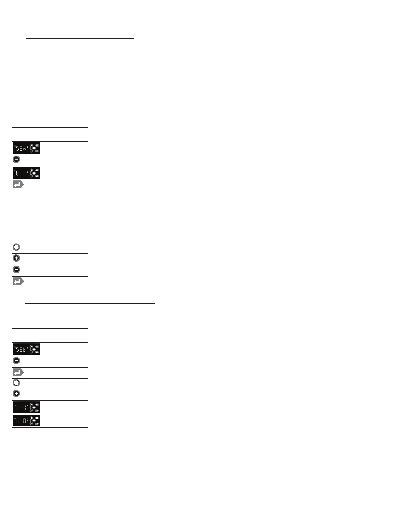
7K - SET DATE & TIME - MENU SYSTEM:
The internal timeclock must be set in order to allow defrost schedule feature to occur at the correct time of day. If the
clock is not set, the control assumes the time is 12 a.m. at the time power is supplied to the unit. The hours on a 24-hour
timeclock read the following way:
h01 = 1:00 a.m. h07 = 7:00 a.m. h13 = 1:00 p.m. h19 = 7:00 p.m.
h02 = 2:00 a.m. h08 = 8:00 a.m. h14 = 2:00 p.m. h20 = 8:00 p.m.
h03 = 3:00 a.m. h09 = 9:00 a.m. h15 = 3:00 p.m. h21 = 9:00 p.m.
h04 = 4:00 a.m. h10 = 10:00 a.m. h16 = 4:00 p.m. h22 = 10:00 p.m.
h05 = 5:00 a.m. h11 = 11:00 a.m. h17 = 5:00 p.m. h23 = 11:00 p.m.
h06 = 6:00 a.m h12 = 12:00 p.m. h18 = 6:00 p.m. h24 = 12:00 a.m.
• Follow the instructions to enter the technician password and Sensor submenu.
• Use the Minus Key until the Time parameter is displayed.
• Press and hold the Enter Key to display the current time in the controller. The Month will
bedisplayedrst,followedbytheDayandthentheYear.TheHours,Minutesand
Seconds will be displayed next. Continue to hold the Enter Keytodisplayalleldsin
theDateandTime.Theeldsareidentiedbytherstcharacter:
o Month
o Day
o Year
o Hours
o Minutes
o Seconds
• Press the Modify KeyandtheMonthseldwillash,indicatingitisbeingmodied.
•TochangeaparticularDate/Timeeld,pressthePlus Key or the Minus Key to set the
eldtothedesiredvalue.
•WhenaDate/Timeeldisacceptable,presstheEnter Key to use the value.
•YoumuststepthroughallsixDate/Timeeldstochangeanyoneeld.
7L - SET DAYLIGHT SAVINGS - MENU SYSTEM:
This parameter is used to adjust the 24-hour clock for Daylight Savings Time. Daylight Savings does not automatically
adjust and must be set manually. The keypad must be unlocked to access the menu system.
• Follow the instructions to enter the technician password and Settings submenu.
• Use the Minus Key until the Daylight Savings Time Flag is displayed.
• Press the Enter Key to display the value of the Daylight Savings Time Flag.
• Press the Modify Keyandthevaluewillash,indicatingitisbeingmodied
• To change the temperature units, press the Plus Key to step through the list of choices:
daylight savings time or daylight standard time.
• When the desired setting is reached, press the Enter Key to lock in the value.
7. MICROPROCESSOR CONTROL (cont’d)
DISPLAY
SYMBOL
DISPLAY
DESCRIPTION
Sensor
Minus Key
Time Parameter
Enter Key
DISPLAY
SYMBOL
DISPLAY
DESCRIPTION
Modify Key
Plus Key
Minus Key
Enter Key
DISPLAY
SYMBOL
DISPLAY
DESCRIPTION
SEt/Settings
Minus (-)
/Previous Key
Enter Key
Modify Key
Plus (+)
/Next Key
Daylight Savings
Time
Daylight Standard
Time
G SERIES
Page 13
G SERIES
Page 14
7. MICROPROCESSOR CONTROL (cont’d)
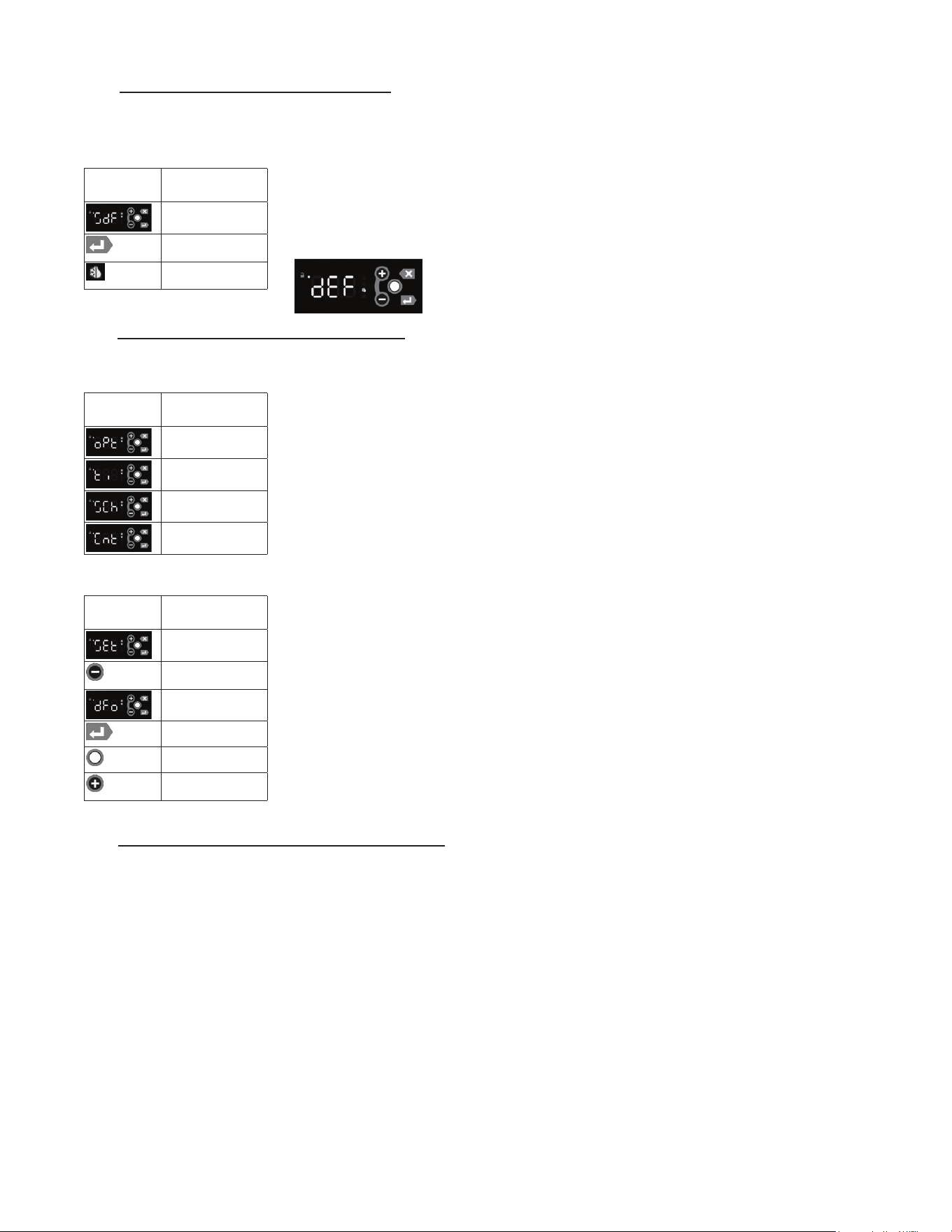
7M - START A DEFROST - MENU SYSTEM:
Defrost can be initiated from the Menu System. Defrost can also be initiated from the Menu System using the short cut
(see section below). The keypad must be unlocked to access the menu system.
• Follow the instructions to enter the customer password and Defrost submenu.
• Press the Enter Key to start the defrost operation.
• The Defrost Symbolwillilluminatelettingyouknowdefrostisineect.
• Depending on the settings, the unit may also show “dEF” (see below).
7N - SET DEFROST MODE - MENU SYSTEM:
TheDefrostModeisusedtocongurethewayinwhichthecontrollerdetermineswhentodefrost.Thepossiblesettings
are:
• Optimize – Defrost based on the ambient conditions (temp & rH)
• Time–DefrosteveryXhours(xedinterval)
• Schedule–Defrostatspecictimes
• Count – Defrost every X compressor cycles
Note 1:Theuserassumesfullresponsibilityforproperlyconguringthedefrostoperation
when using the Defrost Schedule feature. The keypad must be unlocked to access the menu
system.
• Follow the instructions to enter the technician password and Settings submenu.
• Use the Minus Key until the Defrost Mode parameter is displayed.
• Press the Enter Key to display the value of the Defrost Mode parameter.
• Press the Modify Keyandthevaluewillash,indicatingitisbeingmodied.
• To change the Defrost Mode, press the Plus Key to step through the list of choices:
Optimize, Time, Schedule or Count (see above).
• When the desired setting is reached, press the Enter Key to lock in the value.
7O - SET DEFROST SCHEDULE - MENU SYSTEM:
TheDefrostScheduleparametersallowthecustomertocongurethecontrollertodefrosttheunitatspecictimes.Cus-
tomers can set up to six defrost times. They are all programmed the same way. The parameters set the time the defrost
is to start. The options are similar to the 24-hour clock settings. Note 1: the user assumes full responsibility for properly
conguringthedefrostoperationwhenusingtheDefrostSchedulefeature.Note 2: The 24-hour clock must be set for this
feature to operate at the correct time of day. See “Set Date & Time” on page 11. Note 3: The Defrost Mode must be set
to “Schedule” to use the Defrost Schedule feature. See “Set Defrost Mode” on page 12. The keypad must be unlocked
to access the menu system.
DISPLAY
SYMBOL
DISPLAY
DESCRIPTION
Defrost Submenu
Enter Key
Defrost Symbol
DISPLAY
SYMBOL
DISPLAY
DESCRIPTION
Optimize
Time
Schedule
Count
DISPLAY
SYMBOL
DISPLAY
DESCRIPTION
SEt/Settings
Minus (-)
/Previous Key
Defrost Mode
Enter Key
Modify Key
Plus (+)
/Next Key
7. MICROPROCESSOR CONTROL (cont’d)
7O - SET DEFROST SCHEDULE - MENU SYSTEM: (cont’d)
• Follow the instructions to enter the technician password and Settings submenu.
• Use the Plus Key until the Defrost Time 1 is displayed.
• Press and hold the Enter Key to display the value of the defrost time in the controller.
TheHourswillbedisplayedrst,followedbytheMinutesandthentheSeconds.Continueto
hold the Enter Key todisplayalleldsintheDateandTime.Theeldsareidentiedbythe
rstcharacter:
o Hours
o Minutes
o Seconds
• Press the Modify KeyandtheHourseldwillash,indicatingitisbeingmodied.
•TochangeaparticularTimeeld,pressthePlus Key or the Minus Keytosettheeldto
the desired value.
•WhenaTimeeldisacceptable,presstheEnter Key to use the value.
•YoumuststepthroughallthreeTimeeldstochangeanyoneeld.
• When the desired setting is reached, press the Enter Key to lock in the value.
• Use the Plus Key until the Defrost Time 2 is displayed .
• Repeat the steps to program Defrost 2 – Defrost 6
A time of 00:00:00 disables the defrost time (it is not used). To program midnight, enter 24:00:00. The Defrost Times 1 –
6 can be entered in any order. As few as one or as many as six Defrost Times may be entered.
7P - VIEW THE SENSOR TEMPERATURES - MENU SYSTEM:
These parameters allow a service technician or customer to view the temperatures of all sensors within the unit. The tem-
peratures cannot be adjusted. The keypad must be unlocked to access the menu system.
• Follow the instructions to enter the customer password and Sensors submenu.
• Press the Enter Key to enter the Sensors submenu.
•TherstparameterdisplayedwillbetheCabinet Temp (TC = TempCab).
• Press the Enter Key to display the value of the Cabinet Temp.
• Use the Plus Key to move to the next parameter (Evaporator Temp).
• Press the Enter Key to display the value of the Evaporator Temp.
• Use the Plus Key to move through the sensor parameters. The following parameters are available:
o Cabinet Temp
o Evaporator Temp
o Liquid Line Temp
o Dew Point
o Compressor Command
o Evaporator Fan Command
o Condenser Fan Command
o Defrost Heater Command
o Door Heater Command
o Door Switch Status
o Aux Device Command
o Light Command
In General:
• Use the Plus Key and the Minus Key to move through the
Menu System.
• Press the Enter Key to display the value of the selected
parameter.
DISPLAY
SYMBOL
DISPLAY
DESCRIPTION
SEt/Settings
Plus (+)
/Next Key
Defrost Time 1
Enter Key
Hours (value of
defrost trime)
DISPLAY
SYMBOL
DISPLAY
DESCRIPTION
Hours
Minutes
Seconds
DISPLAY
SYMBOL
DISPLAY
DESCRIPTION
Modify Key
Plus (+)
/Next Key
Minus (-)
/Previous Key
Enter Key
DISPLAY
SYMBOL
DISPLAY
DESCRIPTION
Cabinet Temp
Evaporator Temp
Liquid Line Temp
Dew Point
Compressor
Command
Evaporator Fan
Command
Condenser Fan
Command
Defrost Heater
Command
Door Heater
Command
Door Switch
Status
Aux Device
Command
Light Command
DISPLAY
SYMBOL
DISPLAY
DESCRIPTION
Plus (+)
/Next Key
Minus (-)
/Previous Key
Enter Key
G SERIES
Page 15
G SERIES
Page 16
7. MICROPROCESSOR CONTROL (cont’d)
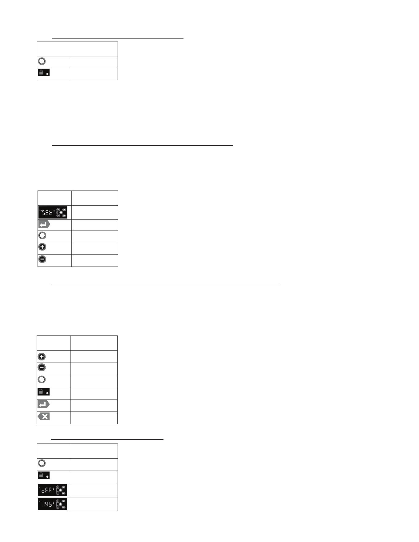
7Q - HOT FOOD - UNLOCKING THE KEYPAD:
Normally, the keypad is locked to prevent inadvertent changes to settings. The Unlock Key is
a white dot on the right side of the display, centered between the other 4 keys.
• Press the Unlock Key twice within a second in order to unlock the keypad (think “tap-tap”).
• The Keypad Unlock LED will turn on to indicate the keypad is now live.
Thekeypadlockisdierentfromthemenupassword.Thekeypadislockedtopreventaccidentalchanges.Oncethe
keypad is unlocked, it is possible to access the menu system. The menu system is password protected. It is necessary to
enter a password in order to view or modify parameters.
The keypad will stay unlocked until there is 3 minutes of inactivity, at which time the controller will automatically lock the
keypad.
7R - HOT FOOD - ADJUST THE SETPOINT - MENU SYSTEM:
This parameter sets the desired cabinet temperature. Please note that hot food units are delivered from the factory set to
the ON position. This parameter is preset at the factory to 145 °F and should set to meet the customer’s requirements.
The setpoint for the unit can be changed from the Menu System. There will be a minimum and maximum value allowed
for the set point. The keypad must be unlocked to access the menu system.
• Follow the instructions to enter the customer password and Settings submenu.
• Press the Enter Key to enter the Settings submenu.
• Use the Plus Key until the Setpoint parameter is displayed.
• Press the Enter Key to display the value of the setpoint .
• Press the Modify Keyandthevaluewillash,indicatingitisbeingmodied
• To raise the setpoint, press the Plus Key to increment to the set point.
Press the Minus Key to lower the setpoint.
• When the desired value is reached, press the Enter Key to lock in the value.
7S - HOT FOOD - CHANGE THE TEMPERATURE SET POINT (SHORT CUT):
The simplest way to change the temperature set point is using the short cut from the Main Display. The set point can also
beconguredfromtheMenuSystem(seepage10).Thesetpointtotheunitcanbechangedbypressingandholdingthe
Plus Key or the Minus Key.Theirwillbeaslightdelayatrsttopreventanaccidentalchange,soitwillbenecessary
toholdthekeyfor2–3secondsuntilthevaluestartstoash.Theashingvalueindicatesthesettingisbeingmodied.
The keypad must be unlocked in order to change the setpoint using the shortcut method.
• Press the Unlock Key twice within a second in order to unlock the keypad (think “tap-tap”).
• The Keypad Unlock LED will turn on to indicate the keypad is now live.
• To raise the setpoint, press and hold the Plus Key to increment to the set point.
Press the Minus Key to lower the setpoint.
•Thevalueonthedisplaywillash.
• When the desired value is reached, press the Enter Key to lock in the value.
• Pressing the Esc Key at any step will abort the process (before the Enter Key is pressed).
7T - HOT FOOD - TURN THE UNIT OFF:
After the temperature has been set, the customer can continuously turn the unit OFF and then
back ON to the same temperature. The keypad must be unlocked in order to de-activate the
hot food unit.
• Press the Unlock Key twice within a second in order to unlock the keypad (think “tap-tap”).
• The Keypad Unlock LED will turn on to indicate the keypad is now live.
• Press and hold the Unlock Key until the display shows “oFF”.
• To turn the unit ON, press the Unlock Key until the display shows the temperature.
DISPLAY
SYMBOL
DISPLAY
DESCRIPTION
Plus (+)
/Next Key
Minus (-)
/Previous Key
Unlock Key
Keypad Unlock
LED
Enter Key
ESC Key
DISPLAY
SYMBOL
DISPLAY
DESCRIPTION
Unlock Key
Keypad Unlock
LED
oFF
Temperature
DISPLAY
SYMBOL
DISPLAY
DESCRIPTION
Unlock Key
Keypad Unlock
LED
DISPLAY
SYMBOL
DISPLAY
DESCRIPTION
SEt/Settings
Enter Key
Modify Key
Plus (+)
/Next Key
Minus (-)
/Previous Key
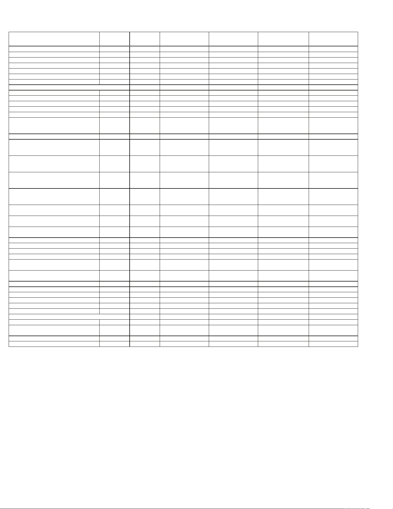
8. SPARE & REPLACEMENT PARTS LISTING
ITEM/DESCRIPTION
G100/G110
1SECREF
G120XX
1SECFZR
G200/G210
2SECREF
G220XX
2SECFZR
G300/G320
3SECREF
G313XX/G310XX
3SECFZR
DOORS
FullHeightGlassDoor 200-60954-01 callfactory allmodels notavailable allmodels notavailable
HalfHightGlassDoor 200-60953-00 callfactory allmodels notavailable allmodels notavailable
HalfHeightGlassDoor 200-60953-01 callfactory allmodels notavailable allmodels notavailable
GASKETS
FullHeightDoor SVC-60256-00 allmodels allmodels allmodels allmodels allmodels
HalfHeightDoor SVC-60257-00 allmodels allmodels allmodels allmodels allmodels
LOCK
Lockkeeper 358-60707-00 allmodels allmodels allmodels allmodels allmodels
LockCylinder 358-13186-42 allmodels allmodels allmodels allmodels allmodels
LockCylinderAssywithKey SER-13186-42 allmodels allmodels allmodels allmodels allmodels
SHELVES/TRAYSLIDES
EpoxyCoatedShelf(withPins&Clips) G1ACC-SHLF5 G1ACC-SHLF5
LFTSEC:G23ACC-SHLF9
RHTSEC:G23ACC-SHLF11
LFTSEC:G23ACC-SHLF9
RHTSEC:G23ACC-SHLF11
LFTSEC:G23ACC-SHLF9
CENSEC:G3ACC-SHLF15
RHTSEC:G23ACC-SHLF11
LFTSEC:G23ACC-SHLF9
CENSEC:G3ACC-SHLF15
RHTSEC:G23ACC-SHLF11
ShelfPin 358-24759-02 allmodels allmodels allmodels allmodels allmodels
3EpoxyCoatedShelves(withPins) G1ACC-SHLF3 G1ACC-SHLF3
LFTSEC:G23ACC-SHLF1
RHTSEC:G23ACC-SHLF5
LFTSEC:G23ACC-SHLF1
RHTSEC:G23ACC-SHLF5
LFTSEC:G23ACC-SHLF1
CENSEC:G3ACC-SHLF5
RHTSEC:G23ACC-SHLF5
LFTSEC:G23ACC-SHLF1
CENSEC:G3ACC-SHLF5
RHTSEC:G23ACC-SHLF5
3EpoxyCoatedShelves(withPilasters&Clips) G1ACC-SHLF2 G1ACC-SHLF2
LFTSEC:G23ACC-SHLF2
RHTSEC:G23ACC-SHLF6
LFTSEC:G23ACC-SHLF2
RHTSEC:G23ACC-SHLF6
LFTSEC:G23ACC-SHLF2
CENSEC:G3ACC-SHLF6
RHTSEC:G23ACC-SHLF6
LFTSEC:G23ACC-SHLF2
CENSEC:G3ACC-SHLF6
RHTSEC:G23ACC-SHLF6
3PlatedShelves(WithPins) G1ACC-SHLF3 G1ACC-SHLF3
LFTSEC:G23ACC-SHLF3
RHTSEC:G23ACC-SHLF7
LFTSEC:G23ACC-SHLF3
RHTSEC:G23ACC-SHLF7
LFTSEC:G23ACC-SHLF3
CENSEC:G3ACC-SHLF7
RHTSEC:G23ACC-SHLF7
LFTSEC:G23ACC-SHLF3
CENSEC:G3ACC-SHLF7
RHTSEC:G23ACC-SHLF7
3PlatedShleves(withPilasters&Clips) G1ACC-SHLF4 G1ACC-SHLF4
LFTSEC:G23ACC-SHLF4
RHTSEC:G23ACC-SHLF8
LFTSEC:G23ACC-SHLF4
RHTSEC:G23ACC-SHLF8
LFTSEC:G23ACC-SHLF4
CENSEC:G3ACC-SHLF8
RHTSEC:G23ACC-SHLF8
LFTSEC:G23ACC-SHLF4
CENSEC:G3ACC-SHLF8
RHTSEC:G23ACC-SHLF8
#1TraySlides-8Pairs(withPilasters) G1ACC-TK1 G1ACC-TK1 LFT/RHTSEC:G23ACC-TK1LR LFT/RHTSEC:G23ACC-TK1LR
LFT/RHTSEC:G23ACC-TK1LR
CENSEC:G3ACC-TK1C
LFT/RHTSEC:G23ACC-TK1LR
CENSEC:G3ACC-TK1C
#4TraySlides-2Pair(withPilasters) G1ACC-TK2 G1ACC-TK2 LFT/RHTSEC:G23ACC-TK2LR LFT/RHTSEC:G23ACC-TK2LR
LFT/RHTSEC:G23ACC-TK2LR
CENSEC:G3ACC-TK2C
LFT/RHTSEC:G23ACC-TK2LR
CENSEC:G3ACC-TK2C
UniversalTraySlides-7Pairs(withPilasters) G1ACC-TK4 G1ACC-TK4 LFT/RHTSEC:G23ACC-TK4LR LFT/RHTSEC:G23ACC-TK4LR
LFT/RHTSEC:G23ACC-TK4LR
CENSEC:G3ACC-TK4C
LFT/RHTSEC:G23ACC-TK4LR
CENSEC:G3ACC-TK4C
LEGS/CASTERS
Legs6"high(setof4) LK1 allmodels allmodels allmodels allmodels allmodels
LOUVERASSY SK-500-60827-00 SK-500-60827-00 SK-500-60827-02 SK-500-60827-02 SK-500-60827-03 SK-500-60827-03
SENSORS
CabinetSensor 334-60083-01 334-60083-01 334-60083-02 334-60083-02 334-60083-03
G313:334-60083-03
G310:334-60405-02
CoilSensor 334-60084-01 334-60084-01 334-60084-02 334-60084-02 334-60084-03
G313:334-60084-03
G310:334-60406-02
LIGHT
LightBuld-LED 358-60691-00 allmodels allmodels allmodels allmodels allmodels
EVAPORATOR
ExpansionValve 325-60080-37 325-60080-25 325-60080-37 325-60080-26 325-60080-38 325-60080-34
EvaporatorMotorAssy(SheetmetalBoxandFanAssy) SK-600-61081-00 SK-600-61081-00 SK-600-61081-00 SK-600-61081-01 SK-600-61081-01 SK-600-61081-01
EvaporatorMotorAssy(MotorAndBladeAssy) 338-60061-00 allmodels allmodels allmodels allmodels allmodels
ExteriorLightSwitch 337-20265-00 notavailable 337-20265-00 notavailable 337-20265-00 notavailable
HotGassLoop 315-60307-00 315-60307-00 315-60307-00 315-60310-00
G300:315-60310-00
G320:315-10041-02
315-10041-02
Relay callfactory callfactory callfactory callfactory callfactory callfactory
StartCapacitor callfactory callfactory callfactory callfactory callfactory callfactory
Note:SameGasketsonbothsolidandglassdoors
Note:Fanbladeandmotorbracketarenolongerneeded
G SERIES
Page 17
G SERIES
Page 18
9. TROUBLE SHOOTING GUIDE
PROBLEM REMEDY
1. Condesning unit fails to start.
a. Check if cord has been disconnected.
b. Check control temperature setting.
2. Condensing unit operates for
prolonged periods or continuously.
a. Are doors closing properly?
b. Dirty condenser lter. Clean properly.
c. Evaporator coil iced. Needs to defrost. See instructions for setting a
manual defrost cycle on page 13.
3. Food compartment is too warm.
a. Check door(s) & gasket(s) for proper seal.
b. Perhaps a large quantity of warm food has recently been added or the door
was kept open for a long period of time. In both cases, allow adequate time
for the cabinet to recover its normal operating temperature.
c. Control setting too high, re-adjust per instructions on page 10.
d. Check that condensing coil is clean.
4. Food compartment is too cold.
a. Perhaps a large quantitiy of very cold or frozen food has recently been
added. Allow adequate time for the cabinet to recover its normal operating
temperature.
b. Adjust the control to a warmer setting, see page 10.
5.Condensation on the exterior surface.
a. Check door alignment & gaskets for proper seal.
b. Condensation on the exterior surface of the unit is perfectly normal during
periods of high humidity.
6. Compressor hums but does not start. a. Call for service.
7. No power to unit.
a. Check if cord & plug has been disconnected.
b. Check power supply breaker.
c. Check ON/OFF switch.

Quality Refrigeration
Form Number: TR35748 | Part Number: 375-60184-00 | Revision Date: 02-2024
Traulsen © All Rights Reserved
4401 Blue Mound Road Fort Worth, Texas 76106 (USA)
Phone: 800.825.8220 | Service Fax: 817.740.6757 | E-mail: [email protected] | Website: traulsen.com