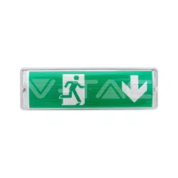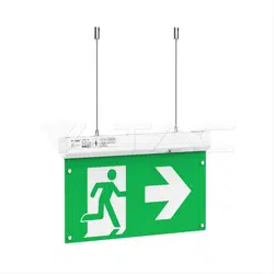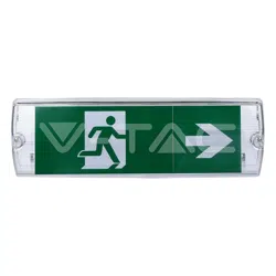
LED EMERGENCY EXIT LIGHT
INTRODUCTION & WARRANTY
Thank you for selecting and buying V-TAC product. V-TAC will serve you the best. Please read these instructions
carefully before starting the installation and keep this manual handy for future reference. If you have any
another query, please contact our dealer or local vendor from whom you have purchased the product. They are
trained and ready to serve you at the best. The warranty is valid for 3 years from the date of purchase. The
warranty does not apply to damage caused by incorrect installation or abnormal wear and tear. The company
gives no warranty against damage to any surface due to incorrect removal and installation of the product. This
product is warranted for manufacturing defects only.
WARNING:
• Please make sure to turn off the power before starting the installation.
• The light source of this luminaire is not replaceable; when the light source reaches its end of life the whole
luminaire shall be replaced.
• Installation should only be done by a certified electrician.
• Proper grounding should be ensured throughout the installation.
• The device must be connected to the main power supply through a fuse dependent by the total amount of
the line’s power load.
• Installation should be carried out in accordance with the latest edition of the wiring regulations and taking
into consideration the latest building regulations.
• Ensure that all electrical connections are tight with no loose strands, including factory made connections.
• Ensure there is adequate free air circulation of at least 100mm around the luminaire. It is the installer’s
responsibility to consider fire risk and take appropriate precautions.
• A seperate enclosure may be required if this unit is to be used in dusty and wet environments.
• The luminaire contains no user replaceable components other than the battery pack contained in emergency
versions.
• The battery has a 2 years warranty provided it is operatedand & maintained by regular testing, as detailed
in this Usermanual. Failure to maintain or change the battery may result in reduced duration in emergency
mode.
• Please make sure to turn off the power before starting the installation.
• Connect the wires as per the wiring diagram. Keep the switch live off, and battery plugged on.
(The green charging indicator on, Faulty indicator off)
• Press the test button, The charging indicator off, and emergency function actived
• Unplugged the battery, charging indicator OFF, the faulty indicator flash in 1HZ.
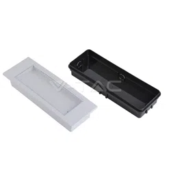
ITEM PARTS
EMERGENCY FUNCTION TEST BEFORE INSTALLATION
INSTALLATION DIAGRAM
3
YEARS
WARRANTY
*
IN CASE OF ANY QUERY/ISSUE WITH THE PRODUCT, PLEASE REACH OUT TO US AT: SUPPORT@V-TAC.EU
FOR MORE PRODUCTS RANGE, INQUIRY PLEASE CONTACT OUR DISTRIBUTOR OR NEAREST
DEALERS. V-TAC EUROPE LTD. BULGARIA, PLOVDIV 4000, BUL.L.KARAVELOW 9B
PACKAGE LIST
The polycarbonate
base
The Spring
Inner Core PCB
The polycarbonate
Cover
The direction Legend
The silcon ring
N
Emergency
Live
N
E
Earth
L
• The mains have to be off during the installation or maintenance.
• Keep the product far from heat sources and in a well ventilated area.
LUMINIAIRE MAY BE LIVE
EVEN IF LAMPS ARE NOT
OPERATING.
ISOLATE MAINS
AND DISCONNECT
BATTERY BEFORE
MAINTENANCE
• Switch off the power before starting the installation.
• Knock out the cable hole
• Install the base on the wall
• Fix the cable by M20
• Connect the cable to the driver
• Connect the battery pack
• Chose right work mode by dip switch
• Fix the middle plate
• Fix the diffuser
• Switch on the power and test the light
INSTALLATION INSTRUCTION
MAINTENANCE INFORMATION
If the above sequence did not apply then the battery will discharge on a certain limit until the battery
protection operation starts.
Minimum recommended test schedule:
• Daily: check that the green indicators is active and the red error indicator is inactive.
• Monthly: check that the green indicators is active and the red error indicator is inactive
(After the monthly self-test).
• Annually: check that the green indicators is active and the red error indicator is inactive
(After the monthly self-test).
ΝΟΤΕ: If red error indicator is activated after any of the above or if the luminaire does not work as
described in this document, contact the installer.
PARTS:
• The luminaire contains no user replaceable components other than the battery pack contained in emergency
versions.
BATTERY:
• It is operated and maintained by regular tests, as described in detail in this document.
• The battery must be replaced in case it cannot support the minimum duration autonomy of 3 hours.
Suspension of product operation: in case of not using the product for a period of the installer must execute
the following steps:
1. Disconnect the main power supply.
2. Press the test button one time.
3. After button is pressed the LED will stop emitting and the operation of battery protection will start.
EMERGENCY LUMINAIRE DESIGNATION
X 1 A*C*E 180
Green charging indicator
LED Chips
TEST button
Battery Pack
LUMINIAIRE MAY BE LIVE
EVEN IF LAMPS ARE NOT
OPERATING.
ISOLATE MAINS
AND DISCONNECT
BATTERY BEFORE
MAINTENANCE
IP65
RATING
This marking indicates that this
product should not be disposed
of with other household wastes.
Caution, risk of electric shock.
MULTI-LANGUAGE
MANUAL QR CODE
Please scan the QR code
to access the manual in
multiple languages.
TECHNICAL DATA
MAINTAINED & NON-MAINTAINED CHANGEOVER
b) Non-Maintained modea) Maintained mode
MAINTAINED & NON-MAINTAINED WORK MODE
a) Dip switch ON. It works in
maintained mode;
b) Or it works in non-maintained
mode.
ON
ON
• Switch off the power before starting the
installation.
• Cut the battery tie and take off the fault
battery.
• Replace with the new battery and tie it
securely. Connect the battery and VH3.96
battery plug properly
• Check if the installation is properly done
before putting back the base cover.
BATTERY REPLACEMENT DIAGRAM
BATTERY REPLACEMENT
INSTRUCTION
Fault Battery
NEW Battery
NEW Battery
20
PAP
GENERAL INSTRUCTIONS
Model VT-996
Emergency Watts >1.2 Watts
Emergency Operation time >3 Hours
Lumen 130lm
Battery Charging Current 150mA
Battery Type LiFePO4, 3.2V 1.5Ah
Test Button Included
Tes t with manual test button
Charging indicate Green LED
Battery protection circuit Included
Low Voltage inspection Inculded
Inhibit mode Inculded
Lamp Type Emergency Bulkhead
Watts maintained mode 3.0W
Non-maintained mode 1.5W
CCT 6400K
CRI >80
Voltage 200-240VAC 50/60Hz
Beam angle 120°
Dimensions L350 * W110 * H56mm
Viewing Distance 22 Meters
Stickers 4 Ways different legends
Material 100% Polycarbonate
LED Chips 18pcs 2835
Warm up time <0.1S
Standard 60598-2-22:2014
Charging time 24 hours
Standard of Legend ISO7010 & ISO3864-1/4
LED lifespan 50,000 Hours
Faulty indicator N/A
Non-maintained mode
If AC supply normal EM LED ON - 130LM
If AC supply failure EM LED OFF - 130LM
Maintained mode
If AC supply normal EM LED ON - 130LM
If AC supply failure EM LED OFF - 0LM
Dimension 110x350x56mm