Loading ...
Loading ...
Loading ...
4 5
However, it must be realised that what is being used
here is the acoustic impedance, not a transfer function.
To take an electrical analogy, consider a passive,
constant-resistance network such as that of gure 6.
While the individual low- (V1) and high-pass (V2)
transfer functions are minimum phase, the sum of the
transfer functions (V1+V2) is not. It is a 2nd-order all-
pass. However, the total input impedance (Zin), is a
pure resistance, R. As such, it is minimum phase. There
is no all-pass (gure 7).
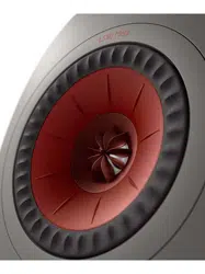
To illustrate that the absorber is indeed minimum-
phase and introduces no time smearing, gure 8 shows
the impulse response of the tweeter dome movement
overlaid with an ideal, minimum phase response.
There is virtually no difference.
The tweeter dome movement was chosen because it
can be measured close-to, which increases the signal
to noise ratio. As it is only valid well below the rst
break-up mode of the dome and the absorber only
works above a certain frequency, both signals were
equally band limited to avoid errors.
Coupling the Absorber to the
Tweeter Dome
The absorber sits at the rear of the Uni-Q™ driver
and is coupled to the tweeter dome by a slightly
tapered conical duct, which acts as a waveguide. This
waveguide passes through the centre poles of both the
tweeter and bass/midrange drivers and has involved a
complete redesign of the tweeter magnet assembly
to accommodate the wider diameter required for the
duct to work properly. The difference in the motor
assemblies is shown in gure 9.
A small amount of porous material is placed in the duct,
which has the dual effects of reducing the amount of
ripple at high frequencies and ne-tuning the knee
of the absorption spectrum. Figure 10 shows the
absorption spectrum immediately behind the dome.
Tangerine Waveguide
Many acoustic engineers would be so pleased at
designing the almost perfect tweeter absorber that
they would have rested on their laurels. But speaker
design is rather like peeling an onion - remove one
layer and there is another one exposed. So it is with the
removal of colouration caused by the rear radiation
not being totally absorbed. It exposed a lesser, but still
important layer of residual colouration. It turned out
that the tangerine waveguide and the dome surround
support - both plastic mouldings - were physically
deforming at high frequencies. (gure 11)
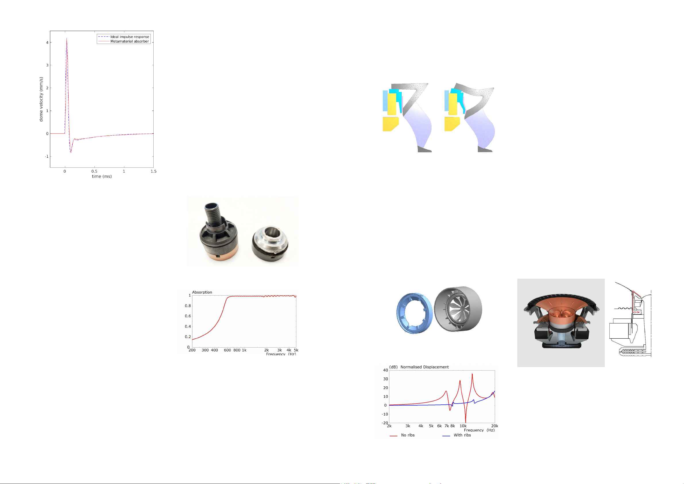
Strengthening ribs were added to both components,
which reduced the deformation. Figure 12 shows
the actual modied parts (viewed from the rear) and
gure 13 illustrates the reduction in displacement.
It should be noted that the modied parts have an
area comparable to the tweeter dome itself and any
movement will add audible colouration to the overall.
For the basic operation of the tangerine waveguide,
featured in previous models, see Appendix 3.
Tweeter Gap Damper
One of the problems with constructing a combination
driver array like Uni-Q is dealing with the gaps that
separate the constituent parts. There is a narrow
channel – an annular gap – between the moving
midrange voice coil and the static start of the tweeter
waveguide. This channel acts as an organ-pipe-like
resonator, and is excited by the tweeter output. The
resonances modify the response of the tweeter, adding
a series of glitches that are not present if the gap is
closed off – simulating a perfectly smooth waveguide.
Obviously, this annular gap is necessary to allow the
LF/MF cone and voice coil to move, so the solution was
to create a cavity between the midrange and tweeter
magnets to which this annular gap connected (gure
14). Adding damping to this newly-created cavity was
found to be effective in taming the resonances in the
annular gap and the removal of the response glitches
was immediately apparent as an improvement in
detail clarity (gure 15).
This feature - the tweeter gap damper - was rst
introduced through the R Series (2018), and was
a major development that led to birth of the 12th
Generation Uni-Q. The addition of MAT and the
change in tweeter system structure for LS50 Meta,
however, necessitated a redesign of the tweeter gap
damper. Additional work was carried out in regards
to the shape of the cavity and the placement of the
wadding material - now comprising of two rings - to
further improve performance.
Figure 8
Impulse response of tweeter dome velocity (red), overlaid with
ideal response (dotted blue)
Figure 10
Absorption at the entrance of the conical duct, immediately
behind the dome diaphragm.
Figure 9
LS50 (left) and LS50 Meta (right) tweeter motor assemblies.
Figure 11
FEA simulation of exaggerated deformation of tangerine
waveguide and surround support at 12kHz
Figure 12
Modied surround support and tangerine waveguide viewed
from the rear to show added ribs
Figure 14
Uni-Q driver with damped, optimised gap
Figure 13
Simulated displacement of tangerine waveguide
Loading ...
Loading ...
Loading ...