IMPORTANT SAFETY INSTRUCTIONS
Carefully read the following important information regarding
installation safety and maintenance.
Keep these instructions for future reference.
0/29/201 MAAN1403-
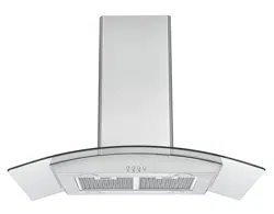
RANGE HOOD
USER INSTRUCTIONS
MODEL:
BREZZA ISLAND 30
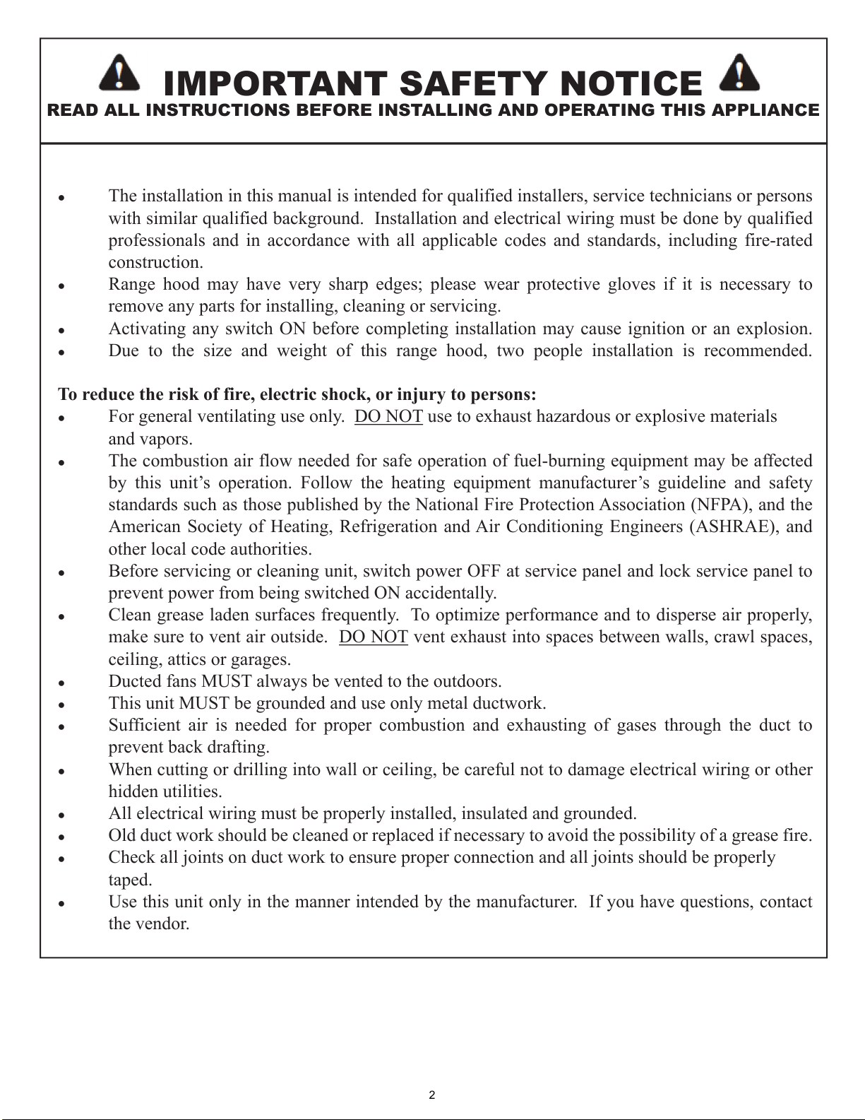
IMPORTANT SAFETY NOTICE
READ ALL INSTRUCTIONS BEFORE INSTALLING AND OPERATING THIS APPLIANCE
● The installation in this manual is intended for qualified installers, service technicians or persons
with similar qualified background. Installation and electrical wiring must be done by qualified
professionals and in accordance with all applicable codes and standards, including fire-rated
construction.
● Range hood may have very sharp edges; please wear protective gloves if it is necessary to
remove any parts for installing, cleaning or servicing.
● Activating any switch ON before completing installation may cause ignition or an explosion.
● Due to the size and weight of this range hood, two people installation is recommended.
To reduce the risk of fire, electric shock, or injury to persons:
● For general ventilating use only. DO NOT use to exhaust hazardous or explosive materials
and vapors.
● The combustion air flow needed for safe operation of fuel-burning equipment may be affected
by this unit’s operation. Follow the heating equipment manufacturer’s guideline and safety
standards such as those published by the National Fire Protection Association (NFPA), and the
American Society of Heating, Refrigeration and Air Conditioning Engineers (ASHRAE), and
other local code authorities.
● Before servicing or cleaning unit, switch power OFF at service panel and lock service panel to
prevent power from being switched ON accidentally.
● Clean grease laden surfaces frequently. To optimize performance and to disperse air properly,
make sure to vent air outside. DO NOT vent exhaust into spaces between walls, crawl spaces,
ceiling, attics or garages.
● Ducted fans MUST always be vented to the outdoors.
● This unit MUST be grounded and use only metal ductwork.
● Sufficient air is needed for proper combustion and exhausting of gases through the duct to
prevent back drafting.
● When cutting or drilling into wall or ceiling, be careful not to damage electrical wiring or other
hidden utilities.
● All electrical wiring must be properly installed, insulated and grounded.
● Old duct work should be cleaned or replaced if necessary to avoid the possibility of a grease fire.
● Check all joints on duct work to ensure proper connection and all joints should be properly
taped.
● Use this unit only in the manner intended by the manufacturer. If you have questions, contact
the vendor.
2
IMPORTANT SAFETY NOTICE
READ ALL INSTRUCTIONS BEFORE INSTALLING AND OPERATING THIS APPLIANCE
To reduce the risk of stove top grease fire:
●
●
●
●
●
●
●
Note: * if included with your model
To reduce the risk of injury to persons in the event of a stove top grease fire:
●
● L PICK UP A P
P MAL AWAY
ACUA CALL PA
● WA
● LY
Y C
Y
To reduce the risk of injury to persons in the event of a gas leaks:
●
●
●
Y We
3
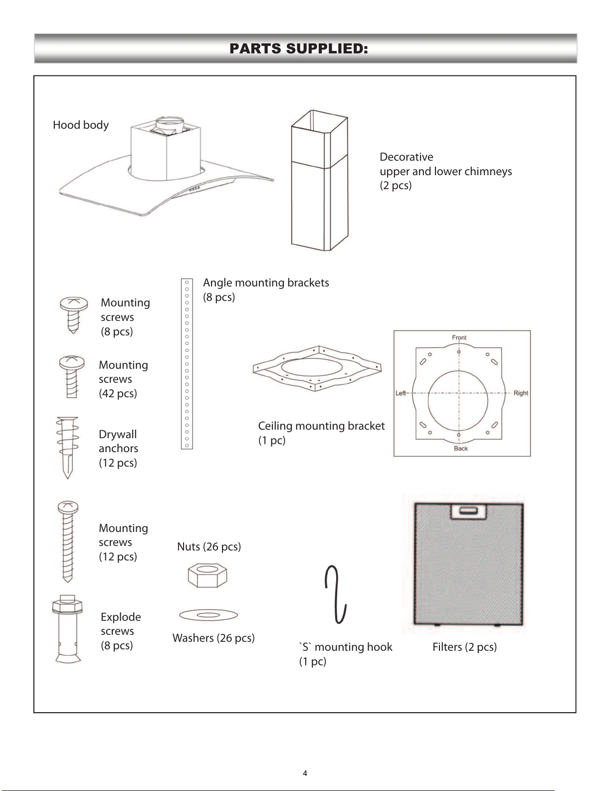
PARTS SUPPLIED:
Decorative
upper and lower chimneys
(2 pcs)
Hood body
Angle mounting brackets
(8 pcs)
Ceiling mounting bracket
(1 pc)
Filters (2 pcs)`S` mounting hook
(1 pc)
Washers (26 pcs)
Nuts (26 pcs)
Explode
screws
(8 pcs)
Mounting
screws
(12 pcs)
Drywall
anchors
(12 pcs)
Mounting
screws
(42 pcs)
Mounting
screws
(8 pcs)
4
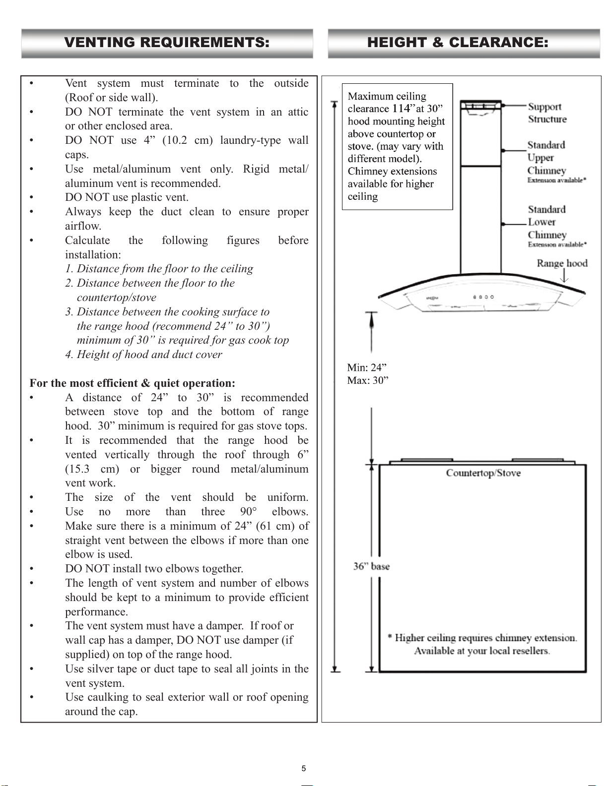
Vent system must terminate to the outside
(Roof or side wall).
DO NOT terminate the vent system in an attic
or other enclosed area.
DO NOT use 4” (10.2 cm) laundry-type wall
caps.
Use metal/aluminum vent only. Rigid metal/
aluminum vent is recommended.
DO NOT use plastic vent.
Always keep the duct clean to ensure proper
airflow.
Calculate the following figures before
installation:
1. Distance from the floor to the ceiling
2. Distance between the floor to the
countertop/stove
3. Distance between the cooking surface to
the range hood (recommend 24” to 30”)
minimum of 30” is required for gas cook top
4. Height of hood and duct cover
For the most efficient & quiet operation:
A distance of 24” to 30” is recommended
between stove top and the bottom of range
hood. 30” minimum is required for gas stove tops.
It is recommended that the range hood be
vented vertically through the roof through 6”
(15.3 cm) or bigger round metal/aluminum
vent work.
The size of the vent should be uniform.
Use no more than three 90° elbows.
Make sure there is a minimum of 24” (61 cm) of
straight vent between the elbows if more than one
elbow is used.
DO NOT install two elbows together.
The length of vent system and number of elbows
should be kept to a minimum to provide efficient
performance.
The vent system must have a damper. If roof or
wall cap has a damper, DO NOT use damper (if
supplied) on top of the range hood.
Use silver tape or duct tape to seal all joints in the
vent system.
Use caulking to seal exterior wall or roof opening
around the cap.
VENTING REQUIREMENTS: HEIGHT & CLEARANCE:
5
IMPORTANT:
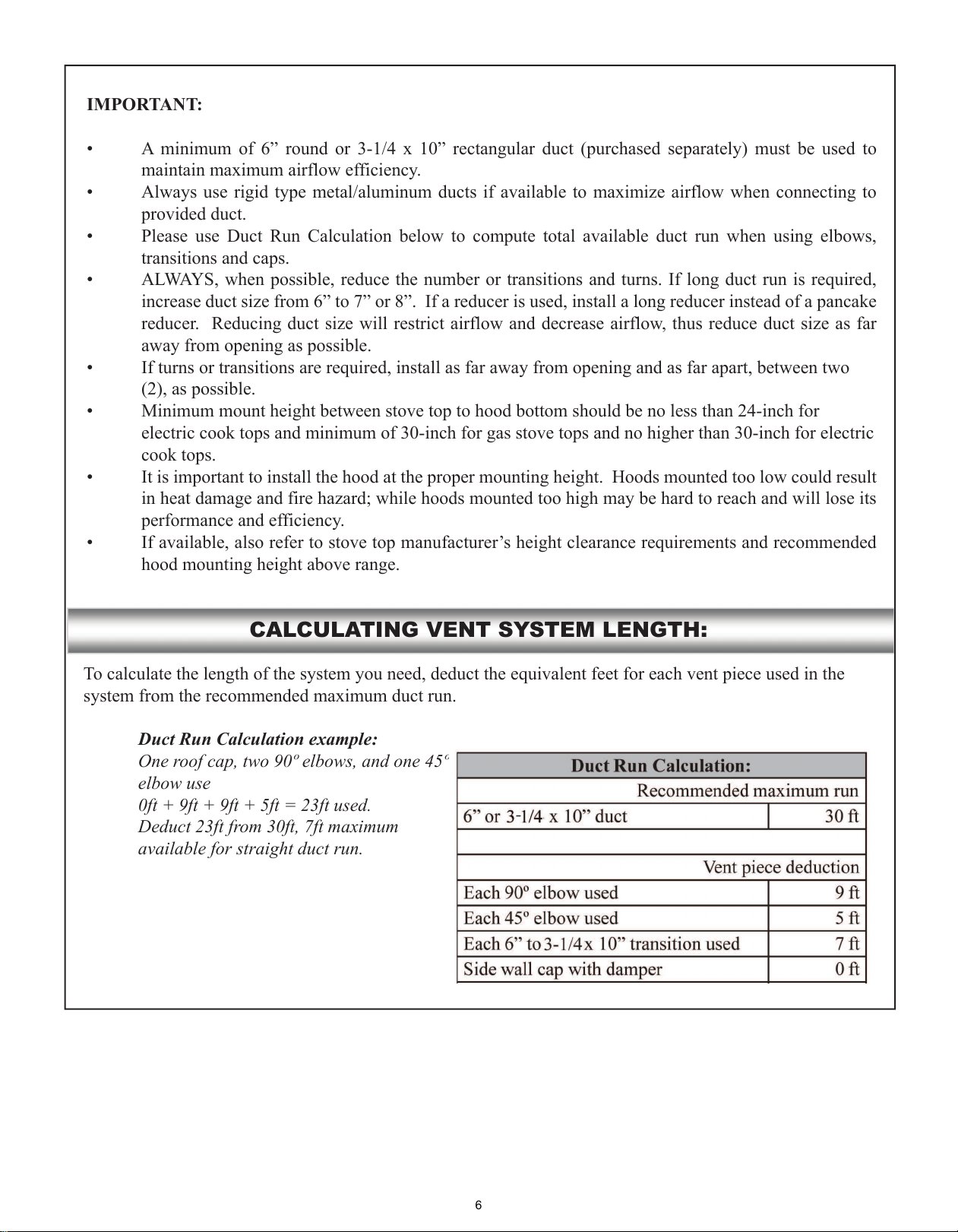
CALCULATING VENT SYSTEM LENGTH:
Duct Run Calculation example:
One roof cap, two 90º elbows, and one 45º
elbow use
0ft + 9ft + 9ft + 5ft = 23ft used.
Deduct 23ft from 30ft, 7ft maximum
available for straight duct run.
-
6
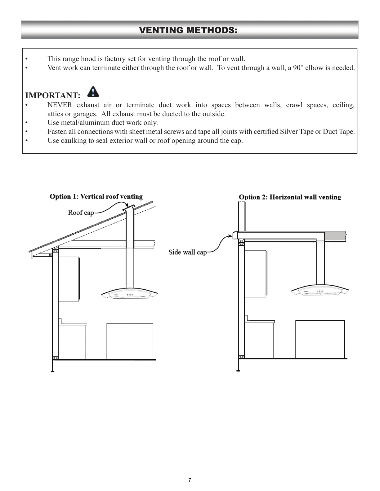
This range hood is factory set for venting through the roof or wall.
Vent work can terminate either through the roof or wall. To vent through a wall, a 90° elbow is needed.
IMPORTANT:
NEVER exhaust air or terminate duct work into spaces between walls, crawl spaces, ceiling,
attics or garages. All exhaust must be ducted to the outside.
Use metal/aluminum duct work only.
Fasten all connections with sheet metal screws and tape all joints with certified Silver Tape or Duct Tape.
Use caulking to seal exterior wall or roof opening around the cap.
VENTING METHODS:
7
IMPORTANT:
Observe all governing codes and ordinances.
It is the customer’s responsibility to contact a qualified electrical installer.
If codes permit and a separate ground wire is used, it is recommended that a qualified electrician determine
that the ground path is adequate.
A 120-Volt, 60 Hz, AC-only, fused electrical supply is required on a separate 15-amp circuit, fused on both
sides of the line.
DO NOT ground to a gas pipe.
Check with a qualified electrician if you are not sure that the range hood is properly grounded.
DO NOT have a fuse in the neutral or ground circuit.
IMPORTANT: Save this Installation Guide for electrical inspector’s use.
The range hood must be connected with copper wire/plug only.
The range hood should be connected directly to the fused disconnect (or circuit breaker) box through
flexible armored or non-metallic sheathed copper cable. UL/CSA listed strain relief must be provided at
each end of the power supply cable.
ELECTRICAL REQUIREMENTS:
8
Advanced Preparations:
Range Hood Operations
Range Hood Operations
Preparations:
NOTE: To avoid damage to your hood, prevent debris from entering the vent opening.
CAUTION
If moving the cooking range is necessary to install the hood, turn OFF the power on an electric range at
the main electrical box. SHUT OFF THE GAS BEFORE MOVING A GAS RANGE
PREPARATIONS:
9
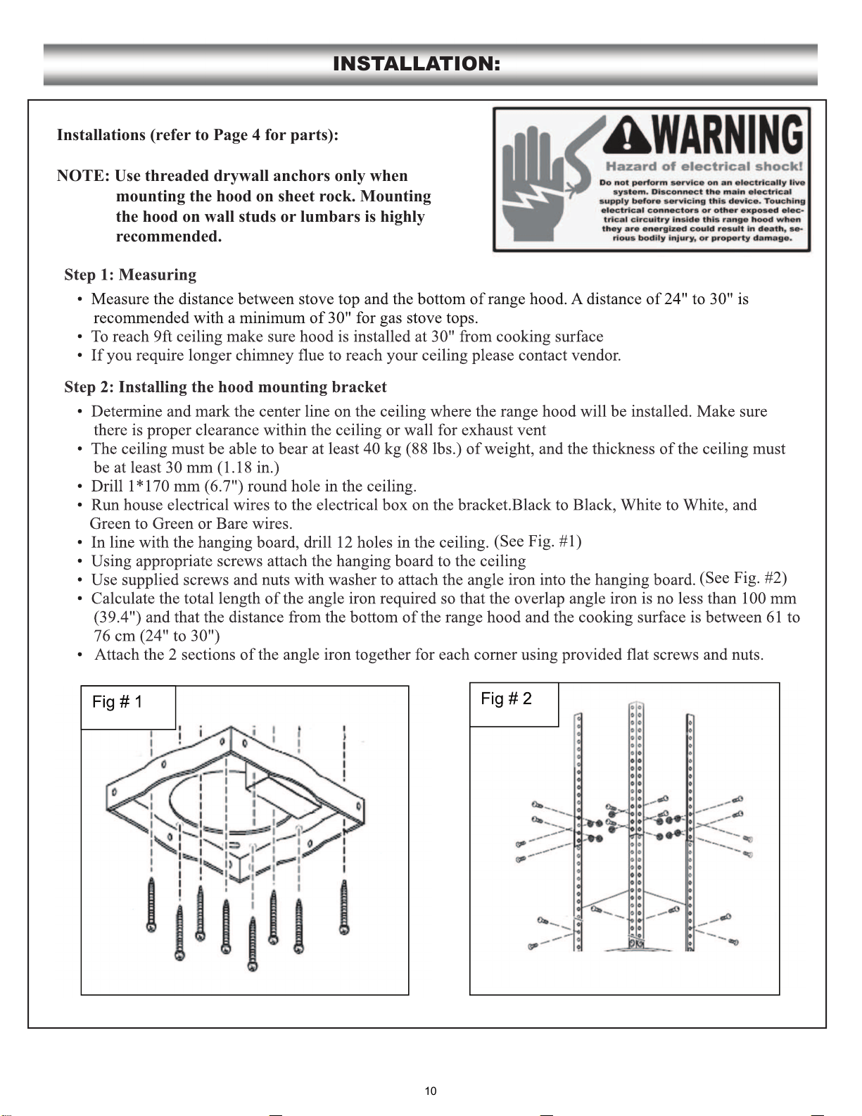
Installations (refer to Page 4 for parts):
NOTE: Use threaded drywall anchors only when
mounting the hood on sheet rock. Mounting
the hood on wall studs or lumbars is highly
recommended.
INSTALLATION:
(See Fig. #1)
(See Fig. #2)
10
INSTALLATION CONTINUE:
Fig # 6
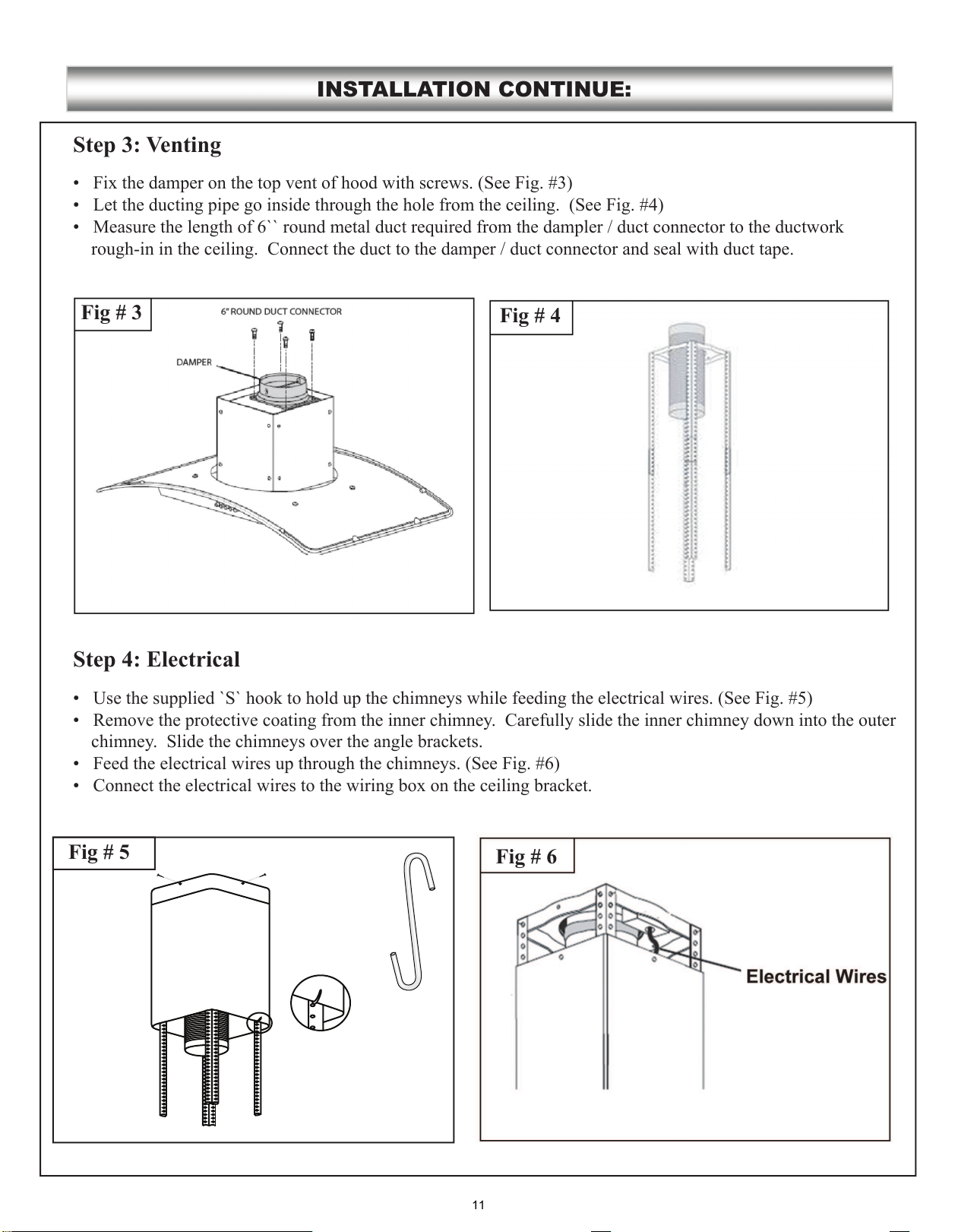
Step 3: Venting
Step 4: Electrical
Fig # 4
Fig # 3
Fig # 5
.................
.................
11
INSTALLATION CONTINUE:
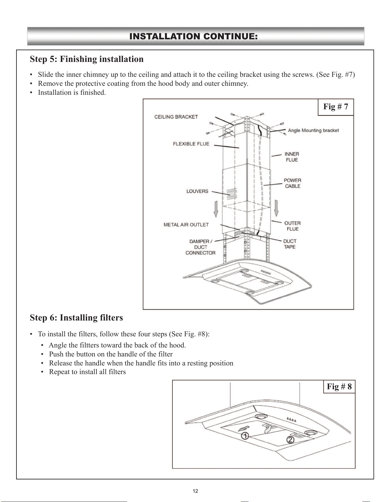
Step 5: Finishing installation
Step 6: Installing filters
Fig # 8
Fig # 7
12
CONTROL PANEL OPERATION:
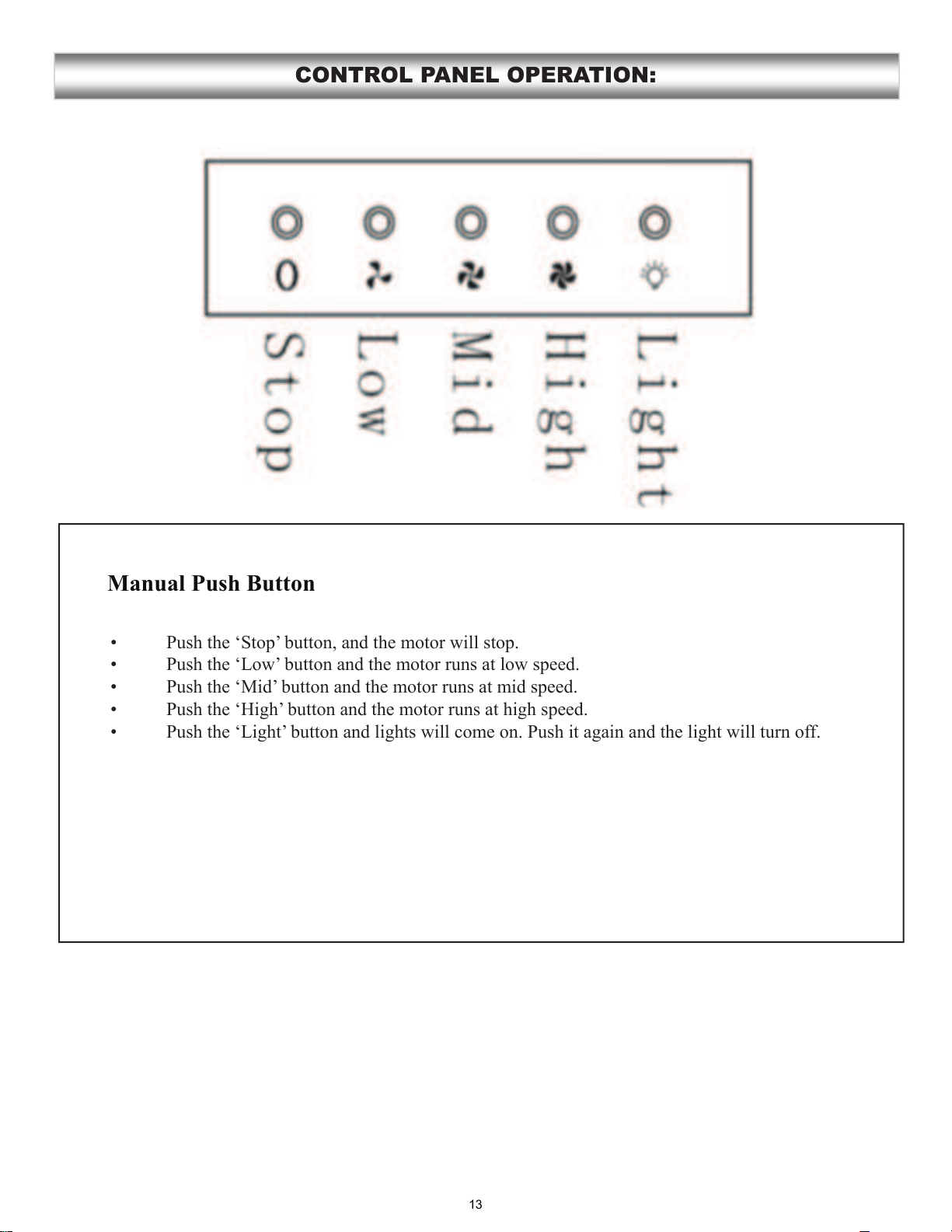
Manual Push Button
13
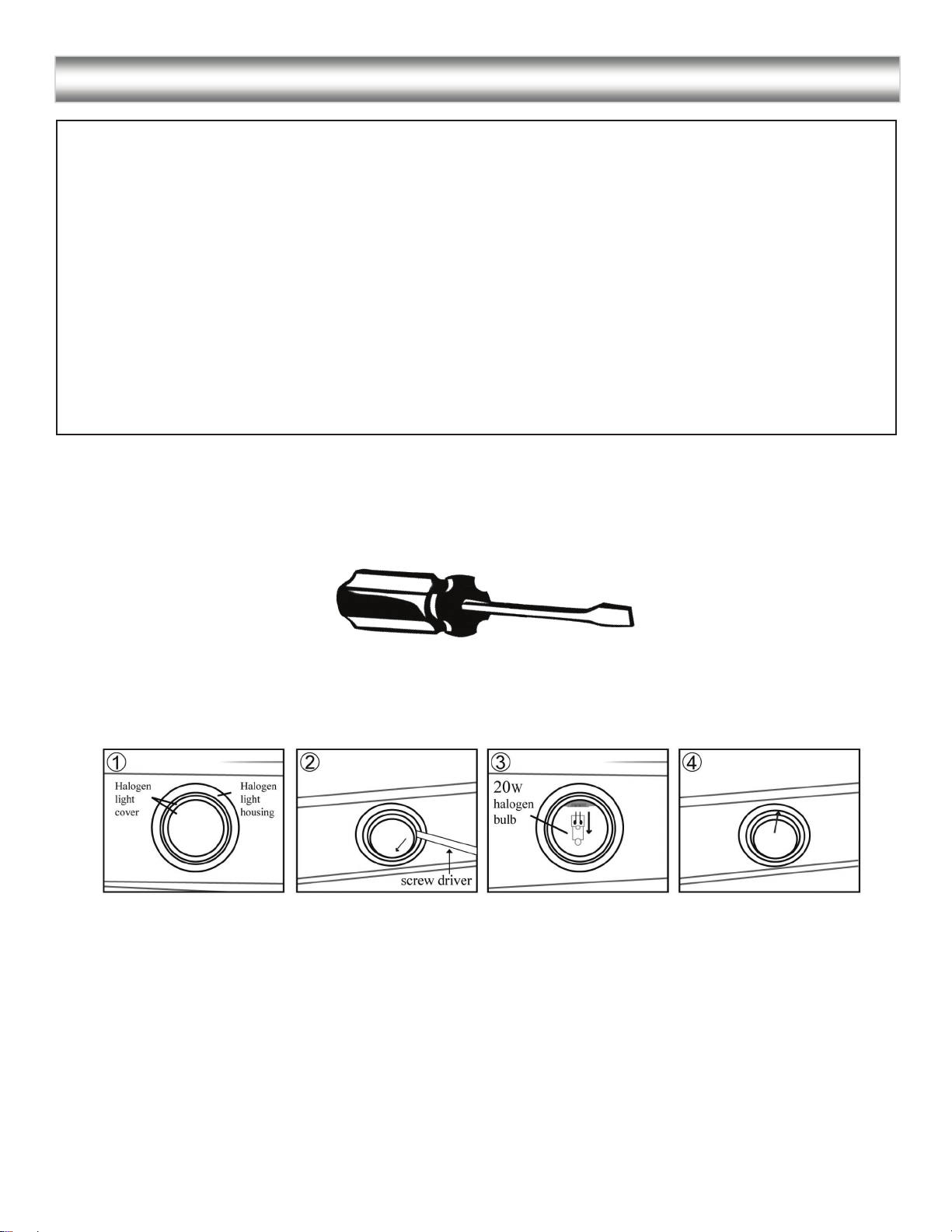
REPLACING THE BULBS:
Replacing the light bulbs:
NOTE:
14
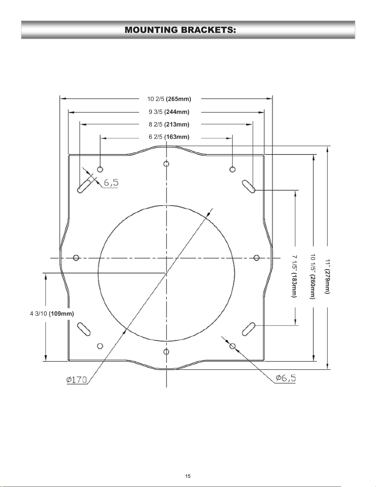
MOUNTING BRACKETS:
15
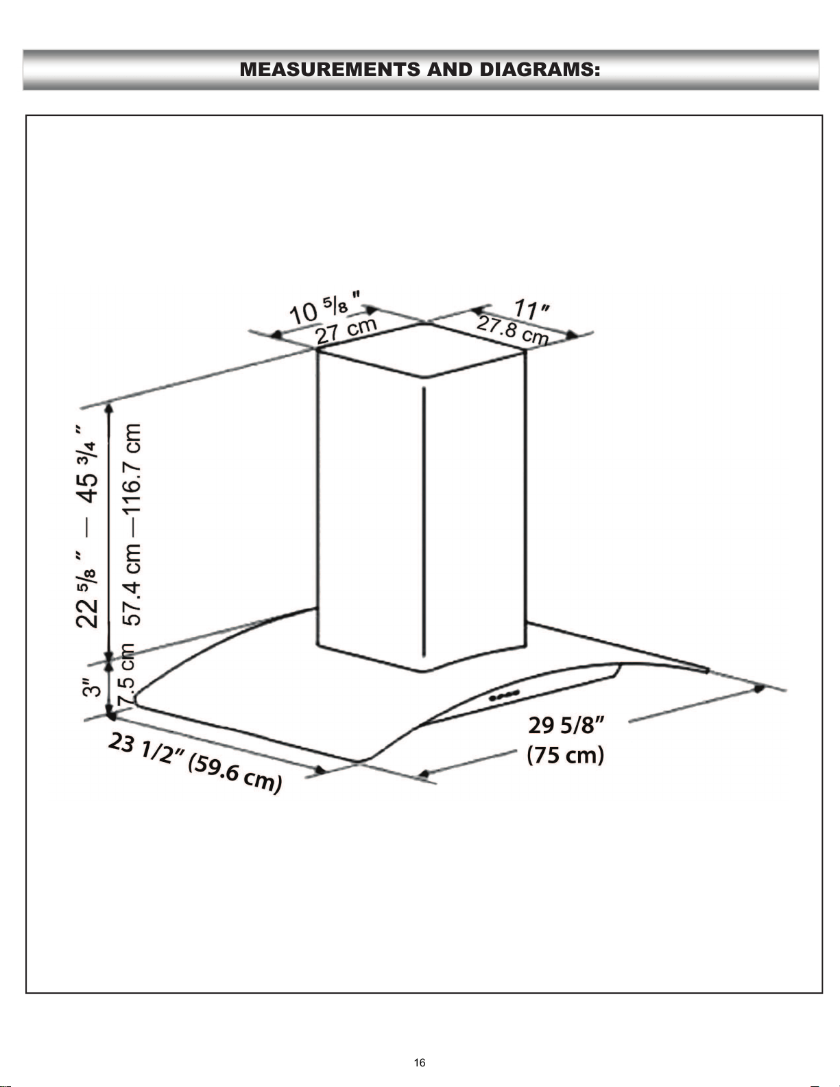
MEASUREMENTS AND DIAGRAMS:
16
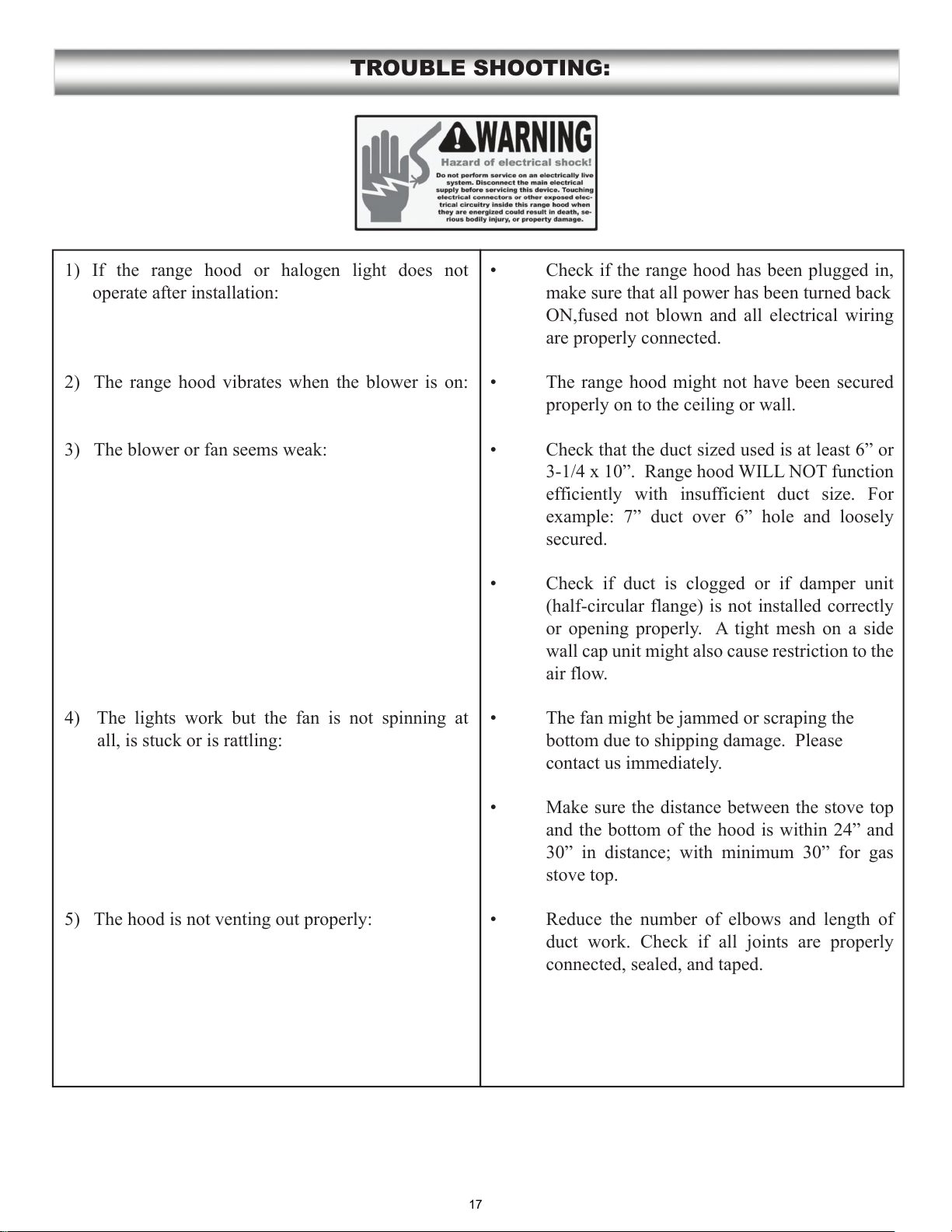
1) If the range hood or halogen light does not
operate after installation:
2) The range hood vibrates when the blower is on:
3) The blower or fan seems weak:
4) The lights work but the fan is not spinning at
all, is stuck or is rattling:
5) The hood is not venting out properly:
TROUBLE SHOOTING:
make sure that all power has been turned back
ON,fused not blown and all electrical wiring
are properly connected.
properly on to the ceiling or wall.
secured.
(half-circular flange) is not installed correctly
or opening properly. A tight mesh on a side
wall cap unit might also cause restriction to the
air flow.
bottom due to shipping damage. Please
contact us immediately.
stove top.
connected, sealed, and taped.
17

RANGE HOOD ASSEMBLY:
No. Part Qty
24 Filter 2
23 Screws 1
22 Lights 4
21 Switch panel 1
20 Push button 1
19 Switch box 1
18 Glass 1
17 Motor 1
16 Wheel 1
15 Blower 1
14 Grill 2
13 Power cord 1
12 Housing 1
11 Air outlet 1
10 Base of plastic box 1
9Connector 1
8Transformer 1
7Capacitor 1
6PCB box 1
5Duct tube (not included) 1
4Lower chimney 1
3Mounting angle 1
2Upper chimney 1
1Mounting plate 1
18
SPECIFICATIONS:
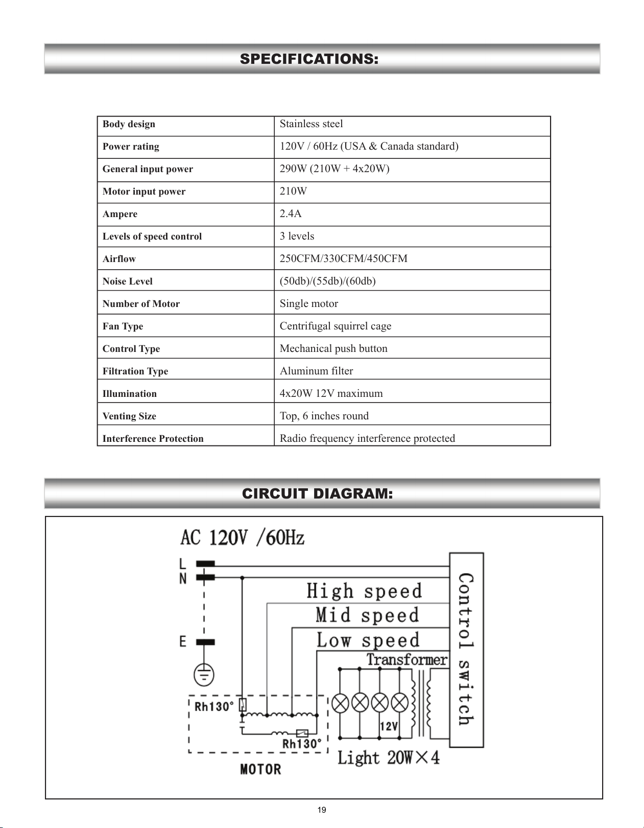
CIRCUIT DIAGRAM:
Body design
Power rating
General input power
Motor input power
Ampere
Levels of speed control
Airflow
Noise Level
Number of Motor
Fan Type
Control Type
Filtration Type
Illumination
Venting Size
Interference Protection
Stainless steel
120V / 60Hz (USA & Canada standard)
290W (210W + 4x20W)
210W
2.4A
3 levels
250CFM/330CFM/450CFM
(50db)/(55db)/(60db)
Single motor
Centrifugal squirrel cage
Mechanical push button
Aluminum filter
4x20W 12V maximum
Top, 6 inches round
Radio frequency interference protected
19
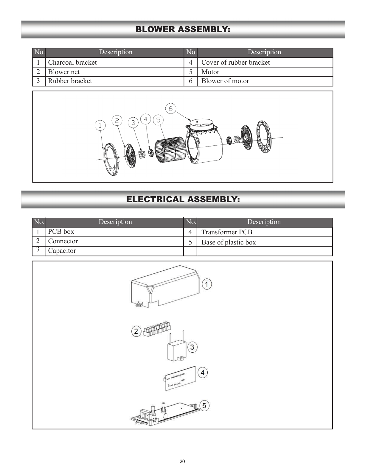
BLOWER ASSEMBLY:
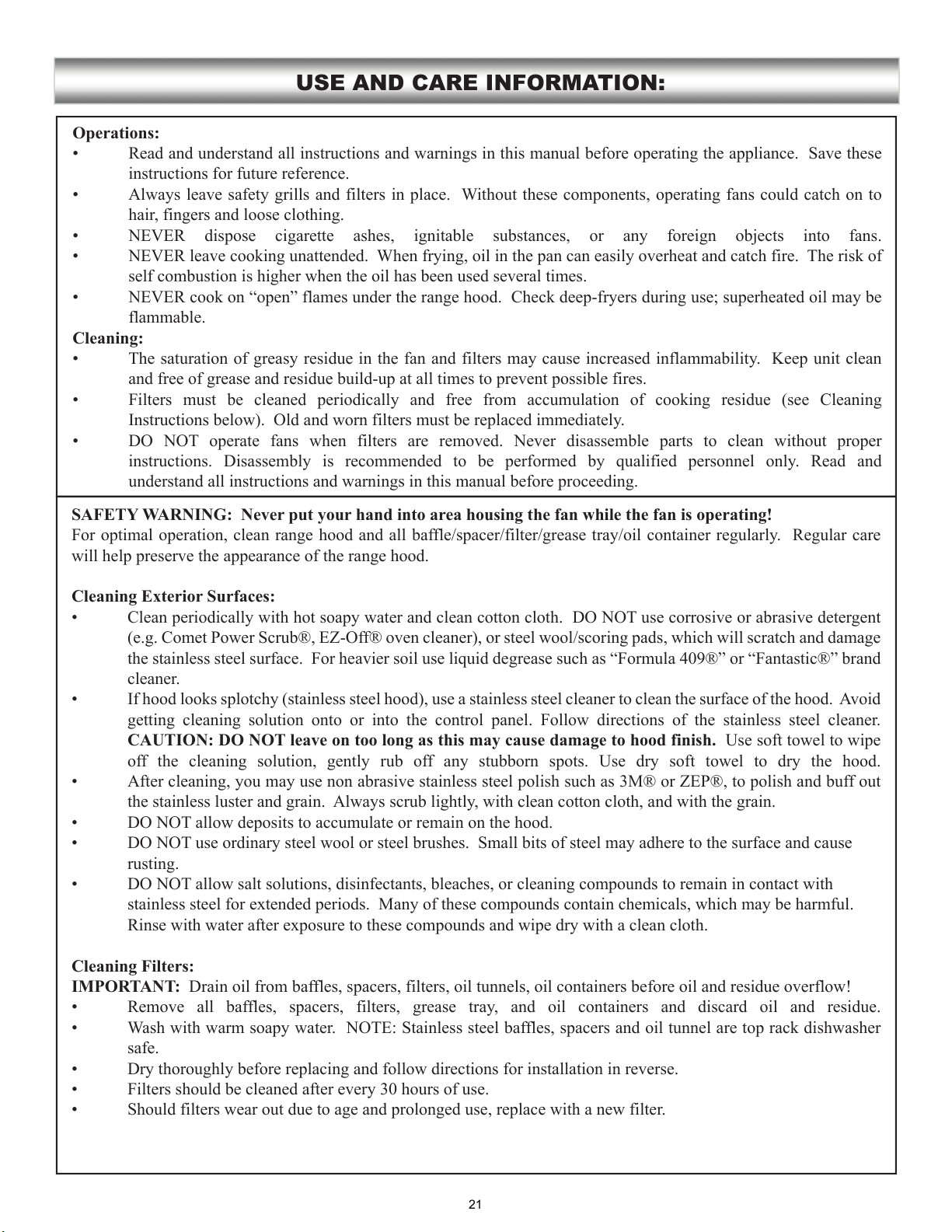
ELECTRICAL ASSEMBLY:
No. No.Description Description
1
2
3
4
5
6
No. No. Description
1
2
3
4
Charcoal bracket
Blower net
Rubber bracket
Cover of rubber bracket
Motor
Blower of motor
Description
PCB box
Connector
Capacitor
Transformer PCB
20
5 Base of plastic box
USE AND CARE INFORMATION:
Operations:
Cleaning:
SAFETY WARNING: Never put your hand into area housing the fan while the fan is operating!
Cleaning Exterior Surfaces:
CAUTION: DO NOT leave on too long as this may cause damage to hood finish.
Cleaning Filters:
IMPORTANT:
21
LIMITED PRODUCT WARRANTY
Subject to the limitations, exclusions and disclaimers hereof, AMS warrants exclusively to the original purchaser (the “Purchaser”) of this
Ancona Range hood product (the “Product”) that it shall be free from defects in material or workmanship (the “Limited Product
Warranty”). The duration of the Limited Product Warranty is 12 months from the date of original purchase (the “Warranty Period”).
The Limited Product Warranty does not extend to commercial or institutional use or installation and to residential or domestic use or
installation outside of Canada and the USA. It is not transferable or assignable to any person.
Any failure of the Product that is not traceable to a defect in material or workmanship is not covered by the Limited Product Warranty. These
non-warrantable items include, but are not limited to: (i) consumable and accessory parts; such as light bulbs or filters; (ii) service outside of
Canada and the USA; (iii) damage caused during shipping, handling or installation; (iv) labour costs related to installation, removal,
reinstallation costs or other contingent expense; or (v) routine replacement of parts due to normal wear and tear of the Product.
If the Purchaser discovers within the Warranty Period a defect in material or workmanship, the Purchaser shall promptly notify AMS in
accordance with the Warranty Claim Procedure set forth below. Within a reasonable time after such notification, AMS shall, at no charge to
the Purchaser: (i) perform any repair or replacement of parts that it determines is necessary or useful to correct any defect in material or
workmanship; or (ii) replace the original Product with a new Product, the whole at AMS’ sole and absolute discretion. The remedy provided
above shall be the Purchaser’s sole and exclusive remedy and AMS' sole and exclusive obligation under the Limited Product Warranty.
Products or parts that are new or reconditioned to perform as new, shall be exchanged by AMS upon receipt of the original Product or parts
from the Purchaser and, upon the completion of such exchange, the original Product or parts shall become AMS’ property. The Warranty
Period shall not be extended due to suspension of the use of the Product because of repair, replacement, examination or for any other reason.
Subject to the Purchaser’s compliance with the Warranty Claim Procedure set forth below, transportation and installation of warranty
replacements shall be performed at AMS’ cost, and AMS shall bear the risk of loss or damage to returned Product or parts while in transit.
AMS’ Limited Product Warranty shall be automatically void if: (i) any repair, alteration, modification, customization, disassembling,
addition or any other work is performed on the Product by any person not authorized by AMS to do so; (ii) any alleged material defect,
including deterioration or wear, is a result of failure to observe the manufacturer’s instructions or guidelines, abuse, misuse, improper
operation, care or maintenance, unusual physical or electrical stress and/or power surges, brown-out, chemical abrasion or improper chemical
or environmental conditions, leaking, fire, lightning, force majeure or superior force, accident, error, negligence, or is a result of use for non-
domestic or non-residential purposes or for any purpose other than the Product’s intended purpose; (iii) the Product is operated in conjunction
with accessories, other products, ancillaries or peripheral equipments or substances that have not been previously approved in writing or
validated by AMS; or (iv) Purchaser fails to comply with the Warranty Claim Procedure set forth below.
THE LIMITED PRODUCT WARRANTY IS EXCLUSIVE AND IN LIEU OF ALL OTHER WARRANTIES OR CONDITIONS
INCLUDING, BUT NOT LIMITED TO, IMPLIED WARRANTIES OR CONDITIONS OF MERCHANTABILITY, FITNESS FOR A
PARTICULAR PURPOSE AND NON-INFRINGEMENT OF THIRD PARTY RIGHTS OF ANY KIND, MADE OR INTENDED BY
AMS OR ITS AUTHORIZED DISTRIBUTORS.
IN NO EVENT SHALL AMS BE LIABLE FOR DAMAGES IN EXCESS OF THE PURCHASE PRICE PAID BY THE PURCHASER
FOR THE PRODUCT, OR FOR ANY INDIRECT, INCIDENTAL, SPECIAL, CONSEQUENTIAL, PUNITIVE, EXEMPLARY OR
OTHER SIMILAR DAMAGES, WHETHER FORESEEABLE OR UNFORESEEABLE, ARISING OUT OF OR IN CONNECTION WITH
THE USE OF THE PRODUCT, INCLUDING THE ABILITY OR THE INABILITY TO USE THE PRODUCT.
The terms hereof and any action in connection therewith, regardless of form, shall be interpreted and construed in accordance with the laws
of the Province of Québec and the laws of Canada applicable therein, without giving effect to principles of conflicts of laws. If a provision of
this Limited Product Warranty is determined to be invalid, illegal or unenforceable, all other provisions will remain in full force and effect.
WARRANTY CLAIM PROCEDURE
In the event a claimable defect occurs, the Purchaser shall call AMS’ customer service department at 1-800-350-4562 in order to obtain a
return authorization number and shipping instructions (the “Authorized Shipping Instructions”).
The Purchaser shall then promptly ship the Product, in accordance with the Authorized Shipping Instructions with the following
documentation/information:
the name and address of the Purchaser;
the Product model number;
the date and location of the purchase of the Product;
the original sales receipt of the Product;
the complete description of the problem;
the name and address of the installer of the Product.
Claims must be filled out in writing and received by AMS within six months of the appearance of the claimable defect.
For service and assistance, please call: 1-800-350-4562, or email us at: info@anconahoods.com
22