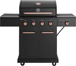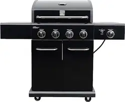

PG-40409S0LB
Item/Artículo :
PG-40409S0LB-1 (Black Chrome)
PG-40409S0LB-2 (Copper Plated)
P/N 4 0 9 0 0 4 9 9
Liquid Propane Gas Grill
User & Care Guide
Manual de Uso y Cuidado
English / Español
Parrilla a gas de propano líquido
Model/Modelo :
If you smell gas:
Please Contact Permasteel Customer Service
For Help & Parts
Product Record
IMPORTANT: Fill out the product record information below.
Model Number ______________________________
Serial Number _______________________________
See rating label on grill for serial number.
Date Purchased ______________________________
DANGER
WARNING
1. Do not store or use gasoline or other
flammable liquid or vapors in the vicinity
of this or any other appliance.
2. An LP tank not connected for use shall
not be stored in the vicinity of this or any
other appliance.
For residential use only. Do not use
for commercial cooking.
CAUTION
CAUTION: Indicates a potentially hazardous situation or
unsafe practice which, if not avoided, may result in minor
or moderate injury.
CAUTION
WARNING: Indicates a potentially hazardous situation
which, if not avoided, could result in death or serious injury.
WARNING
DANGER: Indicates an imminently hazardous situation
which, if not avoided, will result in death or serious injury.
DANGER
Installation Safety Precautions
• Please read this User’s Manual in its entirety before using
the grill.
• Failure to follow the provided instruction can result in
seriously bodily injury and / or property damage.
• Some parts of this grill may have sharp edges. Please wear
suitable protective gloves.
• Use grill, as purchased, only with LP (propane) gas and the
regulator/valve assembly supplied.
• Grill installation must conform with local codes, or in their
absence of local codes, with either the National Fuel Gas
Code, ANSI Z223.1/ NFPA 54, Natural Gas and Propane
Installation Code, CSA B149.1, or Propane Storage and
Handling Code, B149.2, or the Standard for Recreational
Vehicles, ANSI A 119.2/NFPA 1192, and CSA Z240 RV
Series, Recreational Vehicle Code, as applicable.
• All electrical accessories (such as rotisserie) must be
electrically grounded in accordance with local codes, or
National Electrical Code, ANSI / NFPA 70 or Canadian
Electrical Code, CSA C22.1. Keep any electrical cords
and/or fuel supply hoses away from any hot surfaces.
• This grill is safety certified for use in the United States
and/or Canada only. Do not modify for use in any other
location. Modification may result in a safety hazard and
will void the warranty for this grill.
1. Shut off gas to the appliance.
2. Extinguish any open flame.
3. Open lid.
4. If odor continues, keep away from the
appliance and immediately call your gas
supplier or your fire department.
Or visit us at Kenmoregrill.com
If you have any questions or need assistance during
assembly, please call
1-888-287-0735. M-F 8:00AM –
5:00PM PST. You will be speaking to a Representative of the
grill manufacturer.
Safety Symbols
The symbols and boxes shown below explain what each
heading means. Read and follow all of the messages found
throughout the manual.
IMPORTANT: This grill is intended for outdoor use only and is
not intended to be installed in or on recreational vehicles or
boats.
2
NOTE TO INSTALLER: Leave this User’s Manual with the
customer after delivery and / or installation.
NOTE TO CONSUMER: Leave this User’s Manual in a
convenient place for future reference.
TABLE OF CONTENTS
3
WARNING
Combustion by products produced when using this
product include carbon monoxide, a chemical
known to the State of California to cause birth
defects or other reproductive harm. For more
information go to www.P65Warnings.ca.gov
For Your Safety . . . . . . . . . . . . . . . . . . . . . . . . . . . . . . . . . . . . . . . . . . . . . . . . . . . . . . . . . . . . . . . . . . . . . . .
Grill Service Center . . . . . . . . . . . . . . . . . . . . . . . . . . . . . . . . . . . . . . . . . . . . . . . . . . . . . . . . . . . . . . . . . . .
Product Record Information . . . . . . . . . . . . . . . . . . . . . . . . . . . . . . . . . . . . . . . . . . . . . . . . . . . . . . . . . . . . .
Installation Safety Precautions . . . . . . . . . . . . . . . . . . . . . . . . . . . . . . . . . . . . . . . . . . . . . . . . . . . . . . . . . .
Safety Symbols . . . . . . . . . . . . . . . . . . . . . . . . . . . . . . . . . . . . . . . . . . . . . . . . . . . . . . . . . . . . . . . . . . . . . . .
Kenmore Grill Warranty . . . . . . . . . . . . . . . . . . . . . . . . . . . . . . . . . . . . . . . . . . . . . . . . . . . . . . . . . . . . . . .
Use and Care . . . . . . . . . . . . . . . . . . . . . . . . . . . . . . . . . . . . . . . . . . . . . . . . . . . . . . . . . . . . . . . . . . . . . .
Parts List . . . . . . . . . . . . . . . . . . . . . . . . . . . . . . . . . . . . . . . . . . . . . . . . . . . . . . . . . . . . . . . . . . . . . . . . . .
Parts Diagram . . . . . . . . . . . . . . . . . . . . . . . . . . . . . . . . . . . . . . . . . . . . . . . . . . . . . . . . . . . . . . . . . . . . . . . .
Before Assembly . . . . . . . . . . . . . . . . . . . . . . . . . . . . . . . . . . . . . . . . . . . . . . . . . . . . . . . . . . . . . . . . . . .
Assembly . . . . . . . . . . . . . . . . . . . . . . . . . . . . . . . . . . . . . . . . . . . . . . . . . . . . . . . . . . . . . . . . . . . . . . . . .
Troubleshooting . . . . . . . . . . . . . . . . . . . . . . . . . . . . . . . . . . . . . . . . . . . . . . . . . . . . . . . . . . . . . . . . . . .
2
2
2
2
2
4
5-11
12-13
14
15-17
18-28
29-31

4
WARRANTY
KENMORE LIMITED WARRANTY
WITH PROOF OF SALE: the following warranty coverage applies when this appliance is correctly installed,
operated and maintained according to all supplied instructions. Note: Consumer is responsible for Shipping
&handling of all warranty replacement parts.
FOR ONE YEAR: from the date of sale this grill is warranted against defects in material or workmanship,
consumer will receive free replacement parts with proof of purchase, consumer is responsible for Shipping &
Handling cost.
All warranty coverage excludes ignitor batteries and grill part paint loss, discoloration or surface rusting, which
are either expendable parts that can wear out from normal use within the warranty period, or are conditions
that can be the result or normal use, accident or improper maintenance.
All warranty coverage is void if this appliance is ever used for other than private household purposes.
For warranty coverage details to obtain replacement parts, visit the web page: Kenmoregrill.com
This warranty covers ONLY defects in material and workmanship, and will NOT pay for:
1. Service calls to correct appliance installation, or to repair problems with house fuses, circuit breakers, house
wiring, and plumbing or gas supply systems resulting from such installation.
2. Service to an appliance if the model and serial plate is missing, altered, or cannot easily be determined to
have the appropriate certification logo.
3. Expendable items that can wear out from normal use within the warranty period, including but not limited to
batteries, screw-in base light bulbs and surface coatings or finishes.
4. A service technician to clean or maintain this appliance, or to instruct the user in correct appliance installation,
operation and maintenance.
5. Damage to or failure of this appliance resulting from installation, including installation that was not in accord
with electrical, gas or plumbing codes.
6. Damage to or failure of this appliance, including discoloration or surface rust, if it is not correctly operated
and maintained according to all supplied instructions.
7. Damage to or failure of this appliance, including discoloration or surface rust, resulting from accident,
alteration, abuse, misuse or use for other than its intended purpose.
8. Damage to or failure of this appliance, including discoloration or surface rust, caused by the use of
detergents, cleaners, chemicals or utensils other than those recommended in all instructions supplied with the
product.
9. Damage to or failure of this appliance resulting from natural or other catastrophe, such as flood, fire or storm.
10. Damage to or failure of parts or systems resulting from unauthorized modifications made to this appliance.
Disclaimer of implied warranties; limitation of remedies
Customer’s sole and exclusive remedy under this limited warranty shall be product repair or replacement as
provided herein. Implied warranties, including warranties of merchantability or fitness for a particular purpose,
are limited to one year on the appliance and five years on the burners, or the shortest period allowed by law.
Seller shall not be liable for incidental or consequential damages. Some states and provinces do not allow the
exclusion or limitation of incidental or consequential damages, or limitation on the duration of implied warranties
of merchantability or fitness, so these exclusions or limitations may not apply to you.
This warranty gives you specific legal rights, and you may also have other rights which may vary from state to state.
FOR FIVE YEARS: from the date of sale, any stainless-steel burner that rusts through or burns through will be
replaced, proof of purchase must be provided, consumer is responsible for Shipping & Handling cost.
Product distributed by Permasteel, 100 Exchange Place, Pomona, CA 91768. Made in China.
5
USE AND CARE
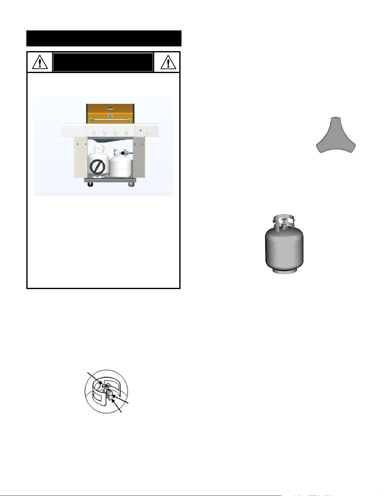
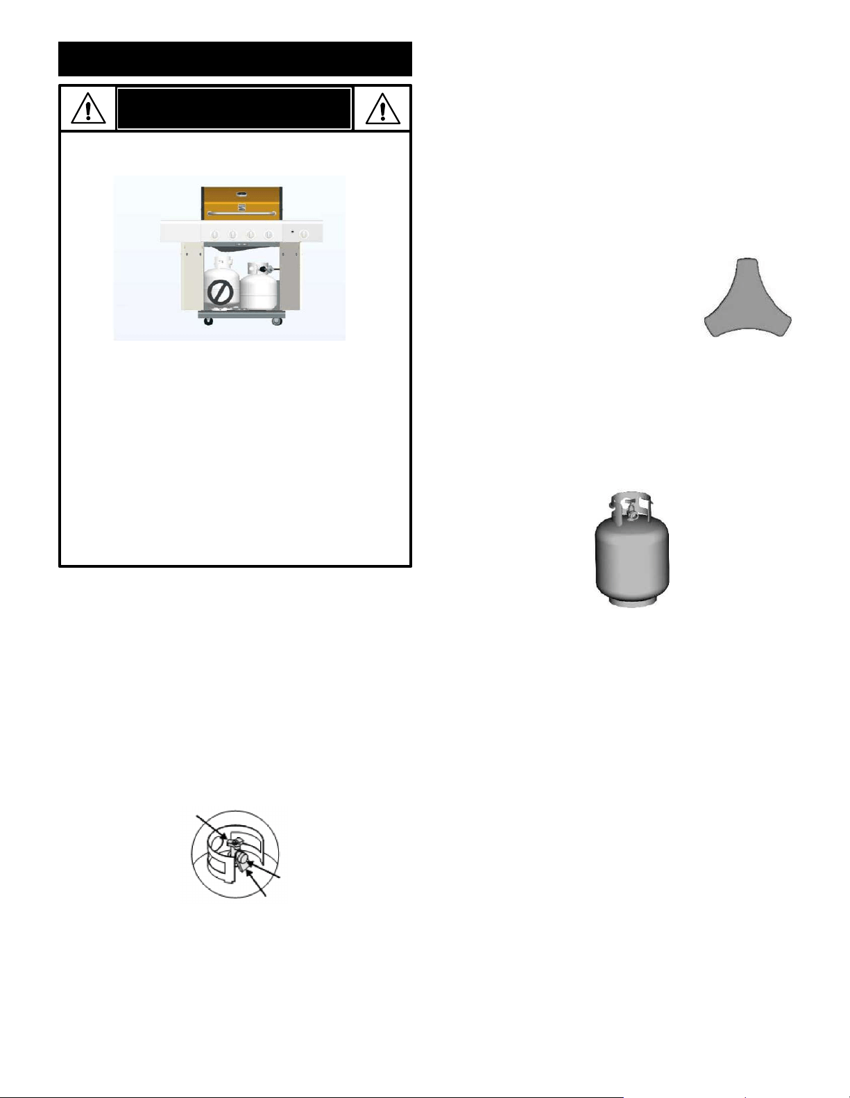
• NEVER store a spare LP tank under or near
the appliance or in an enclosed area.
DANGER
• Never fill a tank beyond 80% full.
• If the information in the two points above is not
followed exactly, a fire causing death or serious
injury may occur.
• An overfilled or improperly stored tank is a
hazard due to possible gas release from the
safety relief valve. This could cause an intense
fire with risk of property damage, serious injury
or death.
• If you see, smell or hear gas escaping,
immediately get away from the LP tank and
appliance and call your fire department.
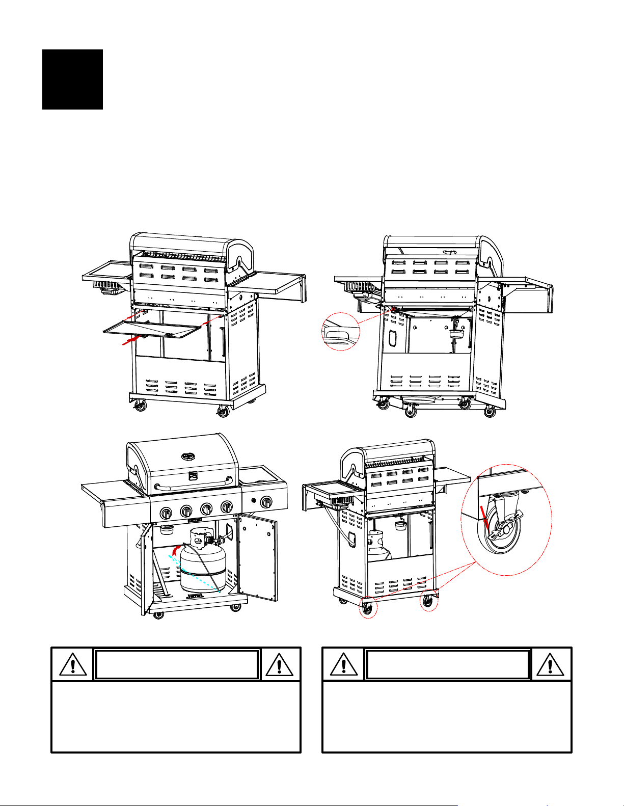
LP Tank Removal, Transport and Storage
• Turn OFF all control knobs and the LP tank valve. Turn
coupling nut counterclockwise by hand only - do not use
tools to disconnect. Lift LP tank retainer strap upward off
the LP tank collar, then lift the LP tank up and off of the
support bracket. Install the safety cap onto the LP tank
valve. Always use cap and strap supplied with the valve.
Failure to use safety cap as directed may result in
serious personal injury and/or property damage.
• A disconnected LP tank in storage or being transported must
have a safety cap installed (as shown). Do not store an LP
tank in enclosed spaces such as a carport, garage, porch,
covered patio or other building. Never leave an LP tank
inside a vehicle which may become overheated by the sun.
• Do not store an LP tank in an area where children play.
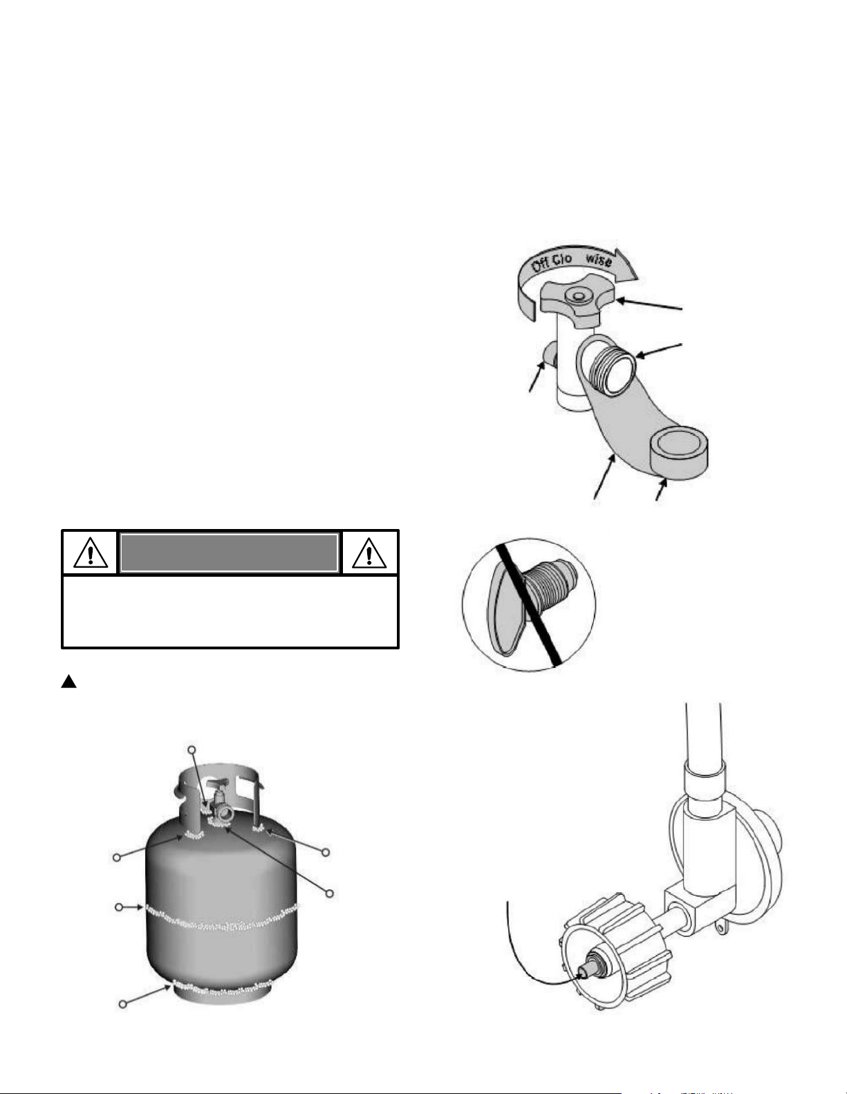
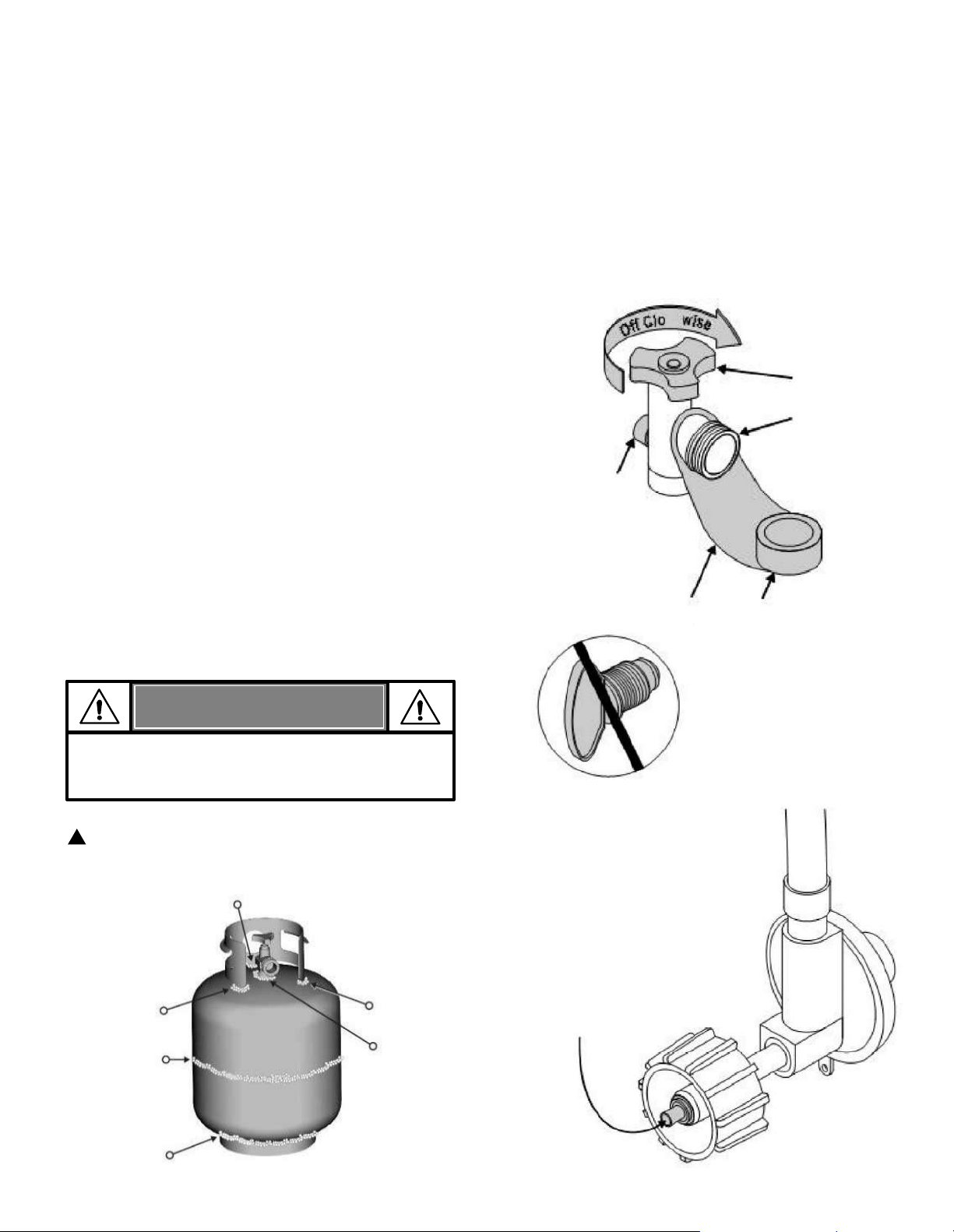
LP Tank Valve
Safety Cap
Retainer Strap
•
The LP tank used with your grill must meet the following
requirements:
• Use LP tank only with these required measurements: 12"
(30.5cm) (diameter) x 18" (45.7 cm) (tall) with 20 lb. (9 kg.)
Capacity maximum.
• LP tank must be constructed and marked in accordance with
specifications for the LP tank of the U.S. Department of
Transportation (DOT) or for Canada, CAN/ CSA-B339,
tanks, spheres and tubes for transportation of dangerous
goods. Transport Canada (TC). See LP tank collar for
marking.
• LP tank valve must have:
• The LP tank must be arranged for vapor withdrawal and
include collar to protect LP tank valve. Always keep the LP
tanks in an upright position during use, transit or storage.
• Type 1 outlet compatible
with regulator or grill.
• Safety relief valve.
•
UL listed Overfill Protection
Device (OPD). This OPD safety
feature is identified by a unique
triangular hand wheel. Only use
the LP tanks equipped with this type of valve.
LP Tank
OPD Hand Wheel
LP (Liquefied Petroleum Gas)
• LP gas is nontoxic, odorless and colorless when produced.
For Your Safety, LP gas has been given an odor (similar to
rotten cabbage) so that it can be smelled.
• LP gas is highly flammable and may ignite unexpectedly
when mixed with air.
LP Tank Filling
• Use only licensed and experienced dealers.
•
LP dealer must purge new tank before filling.
• Dealer should NEVER fill the LP tank more than 80% of LP
tank volume. Volume of propane in tank will vary by
temperature.
• A frosty regulator indicates gas overfill. Immediately close
the LP tank valve and call your local LP gas dealer for
assistance.
• Do not release the liquid propane (LP) gas into the
atmosphere. This is a hazardous practice.
• To remove gas from the LP tank, contact a LP dealer or call
a local fire department for assistance. Check the telephone
directory under “Gas Companies” for your nearest certified
LP dealers.
LP tank in the upright position for vapor withdrawal
6
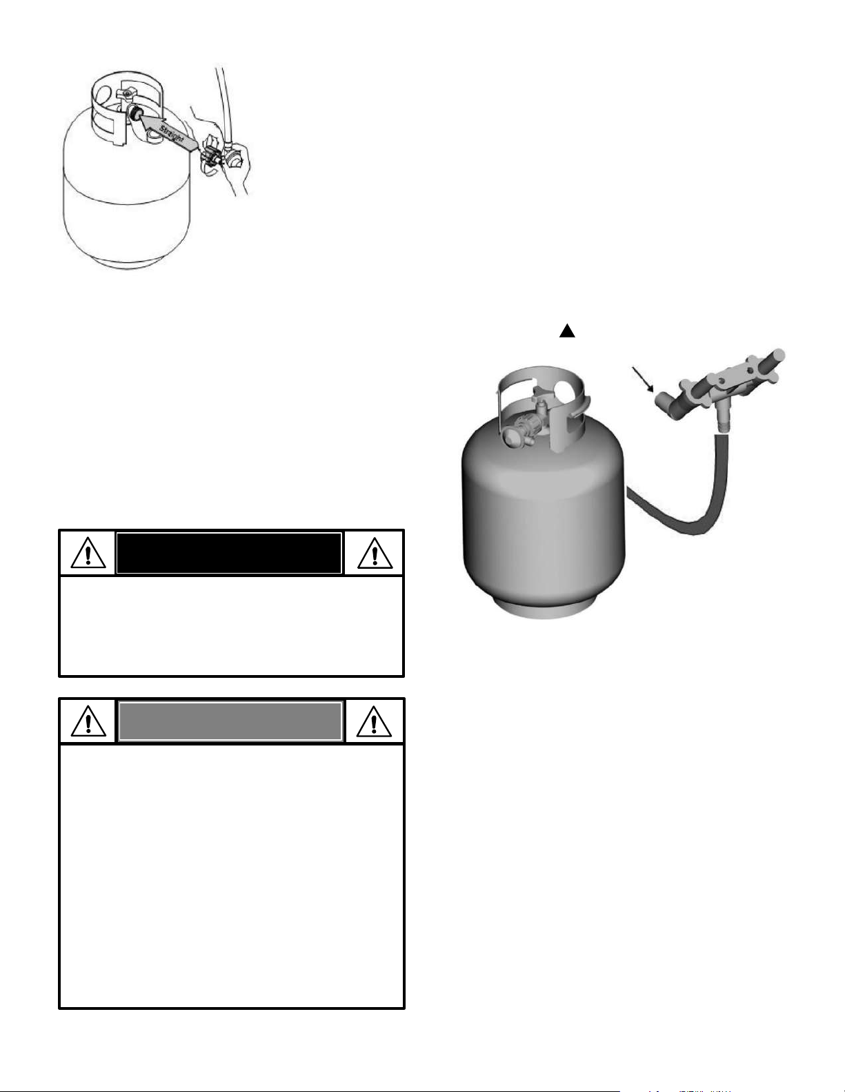
Connecting Regulator to the LP Tank
LP Tank Exchange
1. The LP tank must be properly secured onto the grill. (Refer
to assembly section.)
2. Turn all control knobs to the OFF position.
3. Turn the LP tank OFF by turning the OPD hand wheel
clockwise to a full stop.
4. Remove the protective cap from the LP tank valve. Always
use cap and strap supplied with the valve.
Do not use household cleaning agents. Using Cleaning
agents can result in damage to the gas train
components (valve/hose/regulator).
Nipple has to
be centered into
the LP tank
valve.
5. Hold the regulator and insert the
nipple into LP tank valve. Hand-
tighten the coupling nut, holding
the regulator in a straight line with
the LP tank valve so as not to
cross-thread the connection.
•
Many propane retailers offer the option of replacing
your empty LP tank through an exchange service. Only
use reputable exchange companies that inspect,
precision fill, test and certify their tanks.
Exchange your
tank only for an OPD safety feature-equipped tank as
described in the "LP Tank" section of this manual.
• Always keep your new and exchanged LP tanks in the
upright position during use, transportation or storage.
•
Leak test new and exchanged LP tanks BEFORE
connecting to the grill.
LP Tank Leak Test
• Leak test must be repeated each time a LP tank is
exchanged or refilled.
• Do not smoke during a leak test.
• Do not use an open flame to check for gas leaks.
• The grill must be leak tested outdoors in a well-
ventilated area, away from ignition sources such as gas
or electrical appliances. During the leak test, keep the
grill away from open flames or sparks.
• Use a clean paintbrush and a 50/50 mild soap and
water solution. Brush soapy solution onto areas
indicated by arrows in figure below. Leaks are indicated
by growing bubbles.
For your safety:
WARNING
If “growing” bubbles appear, do not
use or move the LP tank. Contact a LP
gas supplier or your fire department!
Safety Relief Valve
Strap and Cap
Type 1 outlet with
thread on the
outside
OPD Hand
Wheel
Do not insert a POL
transport plug (plastic part
with external threads) into
the type 1 valve outlet. It
will remove the Safety
relief valve feature.
(OFF Clockwise)
7
Leak Testing Valves, Hose and Regulator
1. Turn all grill control knobs to OFF.
2. Be sure regulator is tightly connected to the LP tank.
3. Completely open the LP tank valve by turning the OPD
hand wheel counterclockwise. If you hear a rushing sound,
turn the gas off immediately. There is a major leak at the
connection.
Correct before proceeding. Call for
replacement parts at 1-888-287-0735.
4. Brush soapy solution onto areas where bubbles are.
Never remove threaded
orifice at end of valve
5.
If “growing” bubbles appear, there is a leak. Close the
LP tank valve immediately and retighten connections. If
leaks cannot be stopped do not try to repair. Call for
replacement parts at
1-888-287-0735.
6. Always close the LP tank valve after performing the
leak test by turning hand wheel clockwise.
• If you cannot complete the connection, disconnect the
regulator and repeat steps 5 and 6. If you are still unable
to complete the connection, do not use this regulator!
•
Call for replacement parts at 1-888-287-0735.
NOTE:
WARNING
• Outdoor gas appliance is not intended to be
installed in or on a boat.
• Outdoor gas appliance is not intended to be
installed in or on an RV.
• Never attempt to attach this grill to a self-
contained LP gas system of a camper trailer or
motor home.
• Do not use the grill until a leak test is performed.
• If a leak is detected at any time, STOP and call the
fire department.
• If you cannot stop a gas leak, immediately close
the LP tank valve and call a LP gas supplier or your
fire department!
Hold the coupling nut and
regulator as shown for proper
connection to LP tank valve.
6. Turn the coupling nut clockwise until it is fully tightened.
The regulator will seal on the back-check feature in
the LP tank valve, resulting in some resistance. An
additional one-half to three-quarters turn is required
to complete the connection. Tighten by hand only - do
not use tools.
DANGER
• Do not insert any tools or foreign objects into the
valve outlet or safety relief valve. You may
damage the valve and cause a leak. Leaking
propane may result in an explosion, fire, severe
personal injury, or death.
8
Safety Tips
Before opening the LP tank valve, check the coupling nut for
tightness.
When the grill is not in use, turn off all control knobs and LP
tank valve.
Never move the grill while in operation or still hot.
Use long-handled barbecue utensils and oven mitts to avoid
burns and splatters.
The maximum load for the side burner and side shelf is 10 lbs.
The drip tray must be inserted into the grill and emptied after
each use. Do not remove the drip tray until the grill has
completely cooled.
Clean the grill OFTEN, preferably after each cookout. If a
bristle brush is used to clean any of the grill cooking surfaces,
ensure no loose bristles remain on the cooking surfaces prior
to grilling. It is not recommended to clean cooking surfaces
while the grill is hot.
If you notice grease or other material dripping from the grill;
determine the cause correct it, then clean and inspect the
valve. Keep ventilation openings and tank enclosure (grill
cart) free and clear of debris.
Do not store objects or materials inside the grill cart
enclosure that would block the flow of combustion air to the
underside of either the control panel or the firebox bowl.
The regulator may make a humming or whistling noise during
operation. This will not affect safety or use of the grill.
If you have a grill problem, see the "Troubleshooting Section".
If the regulator frosts, turn off the grill and LP tank valve
immediately. This indicates a problem with the tank, and it
should not be used on any product. Return to supplier!
1. Open the lid during lighting.
2. Turn ON the gas valve on the tank.
3. To ignite, turn the Ignition Burner knob to HI.
4. Push and hold the electronic ignition button.
5. If ignition does not occur in 5 seconds, turn the burner
controls OFF, wait 5 minutes, and repeat the lighting
procedure.
6. To ignite other main burners after the Ignition Burner is lit,
turn a control knob that is adjacent to a lit burner to HI.
Ignite the far left burner last.
7. Once burners are lit, adjust the knobs to the desired flame
setting. To extinguish an individual burner, turn its knob to
OFF.
8. To ignite the Searing Burner, follow steps 3-5 using the
Searing Burner knob.
If the igniter does not work, follow the Match Lighting instructions
on page 9.
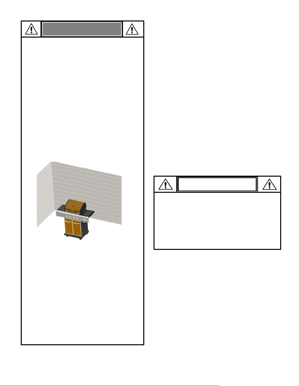
WARNING
• Do not let children operate or play near the grill.
• Keep the grill area clear and free from materials that
burn.
• Do not block the holes on the insides and back of the
grill.
• Use the grill only in well-ventilated space. NEVER use
the grill in an enclosed space such as a carport,
garage, porch, covered patio, or under an overhead
structure of any kind.
• Do not use charcoal or ceramic briquettes in a gas
grill.
• Use the grill at least 3 ft. from any wall or surface.
Maintain 10 ft. clearance to objects that can catch
fire, or to sources of ignition etc.
For Safe Use of Your Grill and to Avoid Serious
Injury:
Check with management to learn the requirements
and fire codes for using an LP gas grill in your
apartment complex. If allowed, use outside on the
ground floor with a three (3) foot clearance from
walls or rails. Do not use on or under balconies.
•
Apartment Dwellers:
• NEVER attempt to light burner with the lid closed.
A buildup of non-ignited gas inside a closed grill is
hazardous.
• Never operate the grill with a LP tank out of position
specified in the assembly instructions.
• Always close the LP tank valve and remove coupling
nut before moving the LP tank from specified
operation position.
▲
▲
▲
▲
▲
▲
▲
▲
▲
▲
▲
▲
Electronic Ignition Lighting Instructions
▲
Do not lean over the grill while lighting.
• Putting out drip fires by closing the lid is not possible.
Grills are well ventilated for safety reasons.
• Do not use water on a drip fire. Personal injury may
result. If a drip fire develops, turn knobs and LP tank
off.
• Do not leave the grill unattended while preheating or
burning off food residue on HI. If the grill has not
been regularly cleaned, a drip fire can occur that
may damage the product.
CAUTION
9
WARNING
Turn your controls, gas source or tank
OFF when not in use.
▲
Do not lean over the grill while lighting.
If ignition does NOT occur in 5 seconds, turn the
burner controls OFF, wait 5 minutes and repeat the
lighting procedure. If the burner does not ignite with
the valve open, gas will continue to flow out of the
burner and could accidently ignite with risk of injury.
CAUTION
Match Lighting Instructions
1. Open the lid during lighting.
2. Place the match into the match holder (hanging on the
left of the side panel).
3. Light the match and insert the match holder through the
lighting hole in the left side of the firebox. Align the lit
match with the first burner on the left.
4. Turn the knob of the first left burner to HI position. Be
sure the burner lights and stays lit. Withdraw the match
holder from the firebox and extinguish the match
5. To light the other burners, turn each knob in succession
to HI.
6. Once the burners are lit, adjust the knobs to the desired
flame setting. To extinguish any individual burner, turn
its knob to OFF.
Searing Burner Match Lighting
1. Open the searing burner lid. Turn on the LP tank.
2. Place the lit match near the burner.
3. Turn the searing burner knob to HI. Be sure the
burner lights and stays lit.
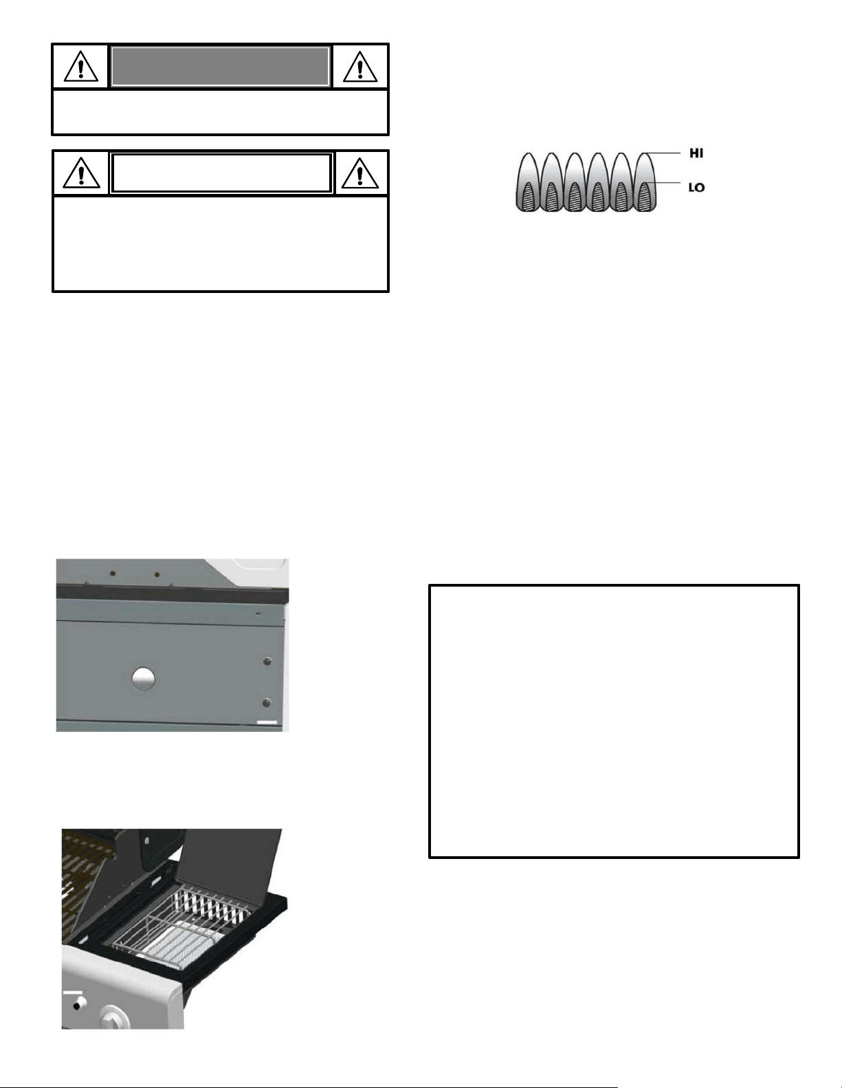
Burner Flame Check
• Remove the cooking grates and heat diffusers. Light the burners
and rotate the knobs from HIGH to LOW. You should see a
smaller flame on the LOW setting and a higher flame on the HI
setting. Always check the flame prior to each use. If only low
flame is seen, refer to the "Sudden drop or low flame" in the
Troubleshooting Section on page 30.
Turning Grill Off
• Turn all knobs to the OFF position. Turn the LP tank off. When you
are finished grilling, raise the grill lid to allow the grill to fully
cool. If the grill lid is closed while the grill is cooling,
condensation may occur on the interior grill surfaces which can
cause the interior parts to rust.
Igniter Check
• Turn the LP tank off. Press and hold the electronic igniter button.
"Click" should be heard and sparks should be seen each time
between the collector box or burner and electrode. See the
Troubleshooting Section on pages 29-31 if there are no clicks or
sparks.
Valve Check
• Important: Be sure the gas in the LP tank is turned off before
checking the valve and the knobs are in the Off Setting. To check
the valves, first push in the knobs and release. The knobs should
spring back. If the knobs do not spring back, replace the valve
assembly before using the grill. Turn the knobs to the LOW
position then turn back to the OFF position. Valves should turn
smoothly.
Hose Check
• Before each use, check to see if hose is cut or worn. Replace
damaged hose before using the grill. Only use the
valve/hose/regulator as specified in the parts list of this Use &
Care Guide.
General Grill Cleaning
• Do not mistake brown or black accumulation of grease and
smoke for paint. Interiors of the gas grills are not painted at the
factory
(and should never be painted). Apply a strong solution
of detergent and water or use a grill cleaner with a scrub brush
to clean the inside of the grill. Rinse and allow the grill to
completely dry.
Do not apply a caustic grill/oven cleaner to the
painted surfaces.
• Porcelain surfaces: Because of the glass-like composition, most
residue can be wiped away with baking soda/water solution or
a specially formulated cleaner. Use a nonabrasive scouring
powder for stubborn stains.
Cast Iron Grate Seasoning (if applicable)
First Use –Before your first use, season your cast iron grates as
follows: Rinse the cast iron grates with hot water. Do not use soap. Dry
the grates thoroughly with a cloth towel. Coat the grates with the
vegetable oil or any non-stick cooking spray. Place the grates in the
grill. Start the grill and slowly raise the temperature to 350° - 400° F.
Heat the grates for one hour. Turn off the grill and allow the grates to
cool completely before using to cook.
Cleaning – Do not use soap when cleaning the grates. Clean the
grates with a stiff brush and hot water. Dry grates thoroughly with a
cloth towel.
Re-seasoning – Re-season the grates when rust spots appear on the
grate surface. When re-seasoning the grates, soap may be used with
hot water to clean the grates. After cleaning, dry the grates
thoroughly with a cloth towel. Coat the grates with vegetable oil or
any non-stick cooking spray. Place the grates in the grill. Start the grill
and slowly raise the temperature to 350° - 400° F. Heat the grates for
one hour. Turn off the grill and allow the grates to cool completely
before using again.
10
Storing Your Grill
• Clean the cooking grates.
• Store in dry location.
• When the LP tank is connected to the grill, store outdoors in a
well-ventilated space and out of reach from children.
• Cover the grill if stored outdoors. Choose from a variety of
grill covers offered by the manufacturer. Available at
Kenmoregrill.com.
• Store the grill indoors ONLY if the LP tank is turned off and
disconnected. Remove the LP tank from the grill and store the
cylinder outdoors.
• When removing the grill from storage, follow the “Cleaning
the Burner Assembly” instructions before starting the grill.
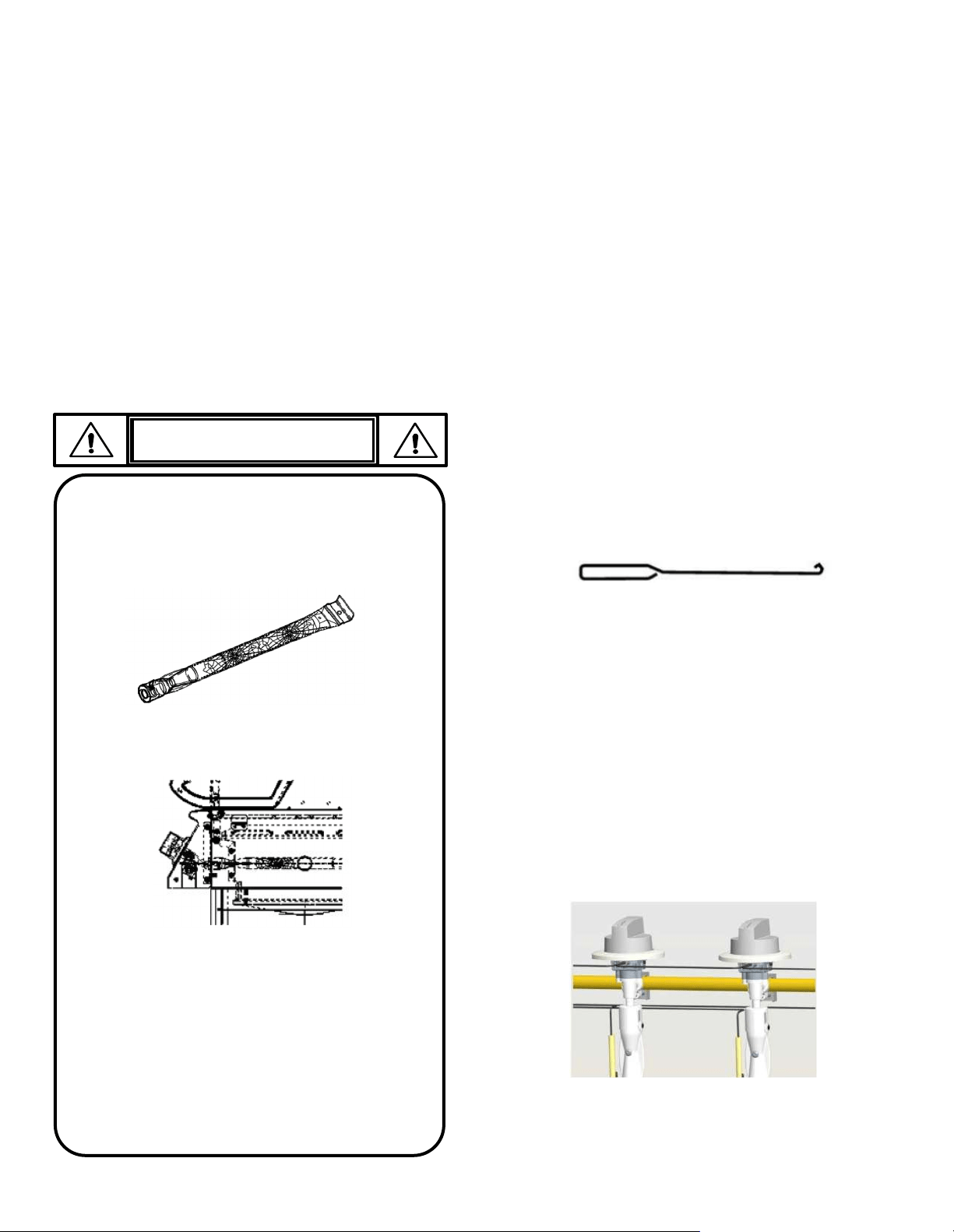
IMPORTANT: Always ensure that the venturi burner
tubes are clean. A venturi burner tube has a narrow area
in which spiders tend to build nests.
CAUTION
SPIDER ALERT!
• Painted surfaces: Wash with a mild detergent or
nonabrasive cleaner and warm soapy water. Wipe dry
with a soft nonabrasive cloth.
• Stainless steel surfaces: To maintain your grill’s high-
quality appearance, wash with a mild detergent and
warm soapy water. Then wipe dry with a soft cloth.
Baked-on grease deposits may require the use of an
abrasive plastic cleaning pad. Use only in direction of
brushed finish to avoid damage. Do not use the abrasive
pad on areas with graphics.
• Cooking surfaces: If a bristle brush is used to clean any of
the grill cooking surfaces, ensure no loose bristles remain
on the cooking surfaces prior to grilling. It is not
recommended to clean the cooking surfaces while the
grill is hot.
• Drip Tray and Cup: When the grill has completely
cooled down after use, remove the drip tray and drip
cup for cleaning.
v
If you notice that your grill is getting hard to light or that
the flame isn’t as strong as it should be, take the time to
check and clean the venturi’s.
Spiders or small insects have been known to create
“flashback” problems. The spiders spin webs, build nests
and lay eggs in the grill’s venturi tube(s), obstructing the
flow of gas to the burner. The backed-up gas can ignite in
the venturi behind the control panel. This is known as a
flashback, and it can damage your grill and even cause
injury.
To prevent flashbacks and ensure good performance the
burner and venturi assembly should be removed from the
grill and cleaned before use whenever the grill has been
idle for an extended period.
Cleaning the Burner Assembly
Follow these instructions to clean and/or replace parts of the
burner assembly or if you have trouble igniting the grill.
1. Turn the gas OFF by turning the control knobs to the off setting
and close the valve of the LP tank.
2. Remove the cooking grates and heat diffusers.
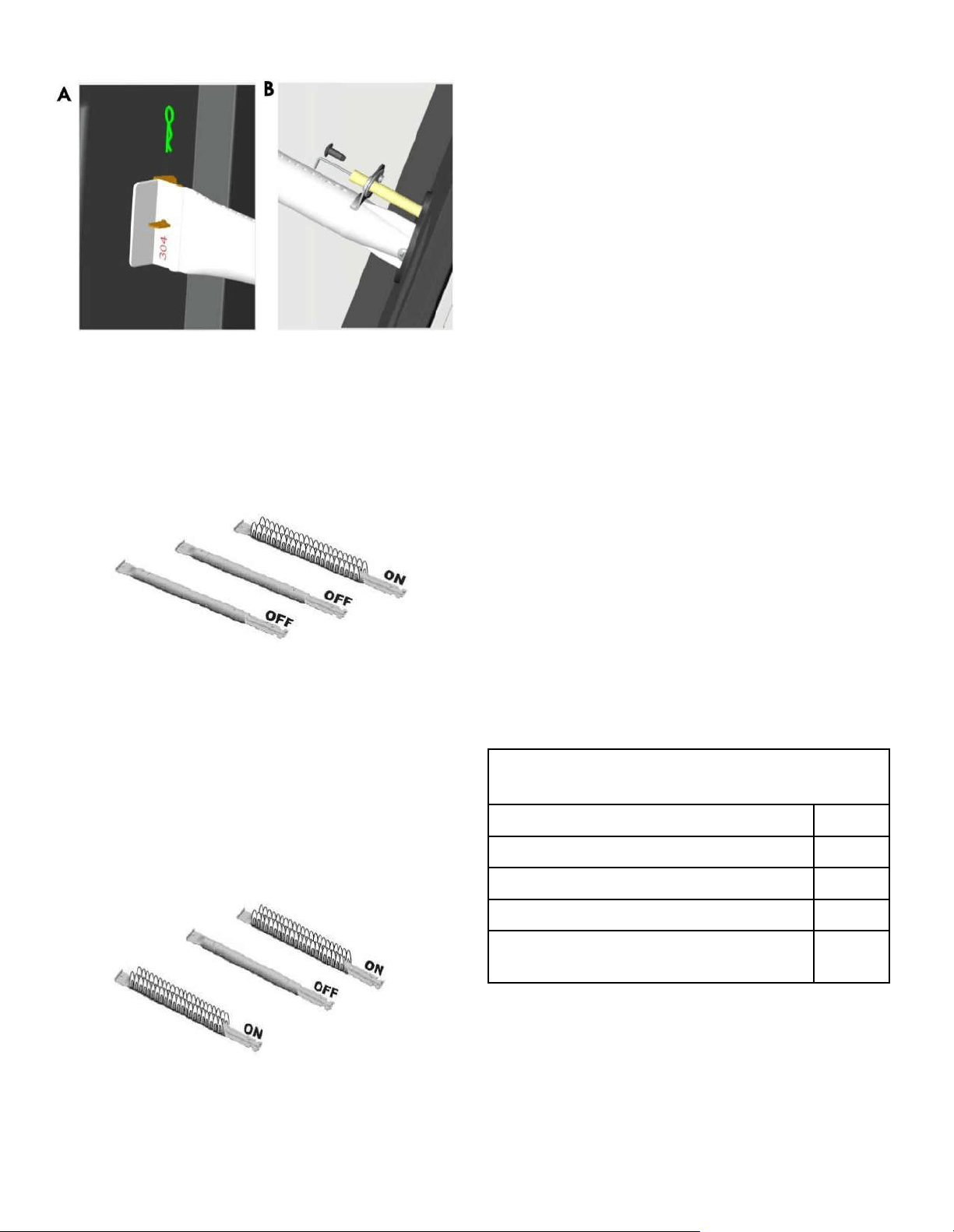
3. Remove the attachment cotter pin from the rear of each
burner. See Fig A on page 11.
4. Carefully lift each burner up and away from valve openings.
We suggest three ways to clean the burner tubes. Use the one
easiest for you.
5. Use a wire brush to scrub the entire outer surface of the
burner to remove food residue and dirt.
6. Clean any blocked ports with a stiff wire such as an open
paper clip.
7. Check the burner for damage. Due to normal wear and
corrosion, some holes may become enlarged. If there are any
large cracks or holes found on the burner, please replace
them.
8. Carefully replace the burners. See Fig. A and B on page 11.
9. Attach the rear of each burner to the bracket and reconnect
the cotter pin. See Fig. A on page 11.
10. Replace the heat diffusers and cooking grates.
(A) Bend a stiff wire (a lightweight coat hanger works well)
into a small hook. Run the hook through each burner tube
several times.
(B) Use a narrow bottle brush with a flexible handle (do not
use a brass wire brush) and run the brush through each
burner tube several times.
(C) Wear eye protection: Use an air hose to force air into
the burner tube and out the burner ports. Check each
port to make sure air comes out of each hole.
VERY IMPORTANT: Burner tubes must re-engage the
valve openings. See illustrations below.
11
Food Safety
Food safety is a very important part of enjoying the outdoor
cooking experience. To keep food safe from harmful bacteria,
follow these four basic steps:
• Clean: Wash hands, utensils, and surfaces with hot soapy
water before and after handling raw meat and poultry.
• Separate: Separate raw meats and poultry from ready-to-
eat foods to avoid cross contamination. Use a clean platter
and utensils when removing cooked foods.
• Cook: Cook meat and poultry thoroughly to kill bacteria.
Use a thermometer to ensure proper internal food
temperatures.
• Chill: Refrigerate prepared foods and leftovers promptly.
For more information call: USDA Meat and Poultry Hotline at
1-800- 535-4555 (In Washington, DC (202) 720-3333, 10:00
am 4:00 pm EST).
How to Tell if Meat is Grilled Thoroughly
• Meat and poultry cooked on a grill often browns very fast
on the outside. Use a meat thermometer to be sure food
has reached a safe internal temperature and cut into the
food to check for visual signs of doneness.
• Whole poultry should reach 180° F; breasts, 170° F. Juices
should run clear, and the flesh should not be pink.
• Hamburgers made of any ground meat or poultry should
reach 160° F and be brown in the middle with no pink
juices. Beef, veal and lamb steaks, roasts and chops can be
cooked to 145° F. All cuts of pork should reach 160° F.
• NEVER partially grill meat or poultry and finish cooking
later. Cook food completely to destroy harmful bacteria.
• When reheating takeout foods or fully cooked meats like
hot dogs, grill to 165° F, or until steaming hot.
WARNING: To ensure that it is safe to eat, food must be
cooked to the minimum internal temperatures listed in the table
below.
Indirect Cooking
Poultry and large cuts of meat cook slowly to perfection on
the grill by indirect heat. Place food over the unlit burner(s);
the heat from the lit burners circulates gently throughout the
grill, cooking the meat or poultry without the touch of a
direct flame. This method greatly reduces flare-ups when
cooking extra fatty cuts because there is no direct flame to
ignite the fats and juices that drip during cooking.
Indirect Cooking Instructions
• Always cook with the lid closed.
• Once the burners are lit, extinguish any individual burner
by turning its knob to OFF.
• Due to weather conditions, cooking times may vary.
During cold and windy conditions, the temperature setting
may need to be increased to insure sufficient cooking
heat.
• Place food over unlit burner(s).
1 Burner Cooking
Consumes less fuel.
2 Burner Cooking
Great indirect cooking on low. Produces
slow and even heating. Ideal for slow
roasting and baking.
* United States Department of Agriculture
** Allow meat to rest for three minutes before carving or
consuming.
USDA *Recommended Safe Minimum Internal
Temperatures
Beef, Veal, Lamb, and Pork: Whole Cuts** 145°F
Fish 145°F
Beef, Veal, Lamb, and Pork: Ground 160°F
Egg Dishes 160°F
Turkey, Chicken, and Duck: Whole, Pieces, and
Ground
165°F
12
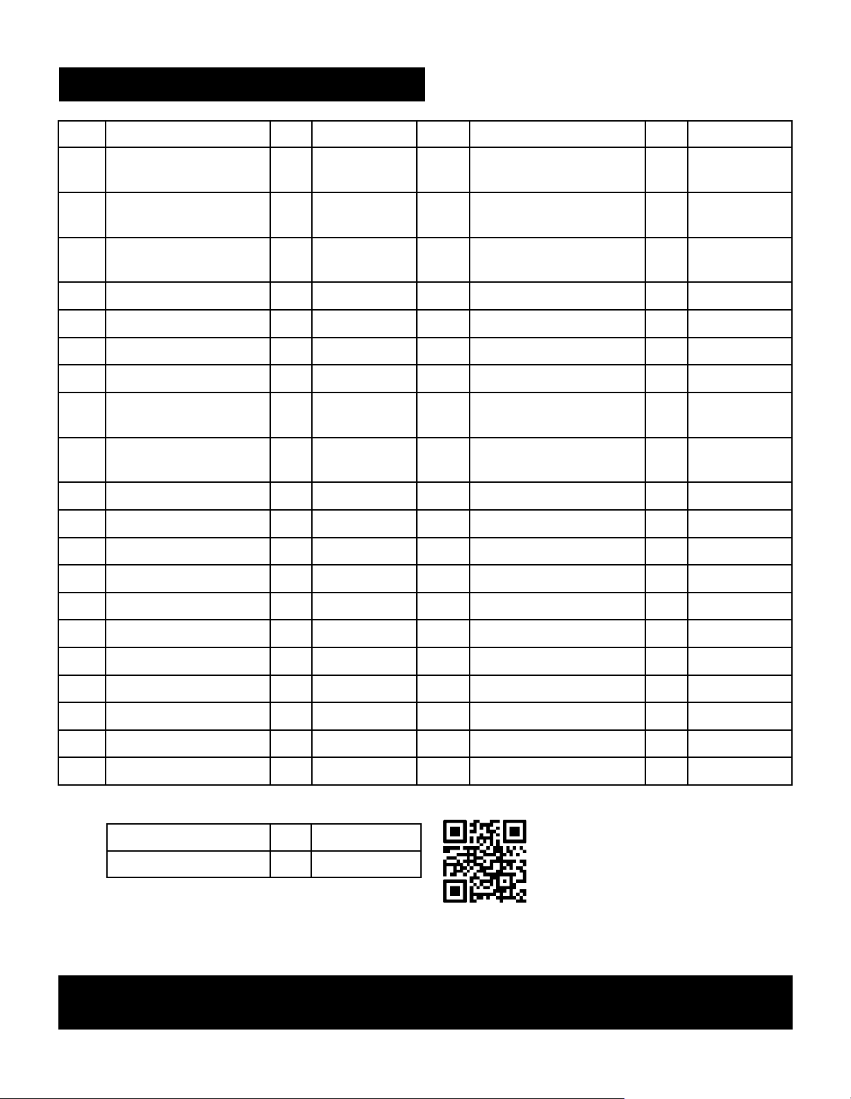
NOTE: Some grill parts shown in the assembly steps may differ slightly in appearance from those on
your particular grill. However, the method of assembly remains the same.
Key Description Qty Part Number Key Description Qty Part Number
1 Side Burner Lid 1 40200500 18 Regulator 1 40800115
2 Rotate Rod, Side Burner Lid 1 40900221 19-A
Control Knob Bezel
(Matte Black)
5 40920036
3 Side Burner Grid 1 40900222 19-B
Control Knob Bezel
(Black Chrome)
5 40900502
4 Searing Burner 1 40900142 20-A
Control Knob, Main Burner
(Copper Chrome)
4 40920206
5 Searing Burner Wire 1 40900220 20-B
Control Knob, Main Burner
(Black Chrome)
4 40900517
6 Searing Burner Base 1 40900114 21-A
Control Knob, Searing Burner
(Copper Chrome)
1 40920224
7 Drip Box, Searing Burner 1 40900116 21-B
Control Knob, Searing Burner
(Black Chrome)
1 40900505
8 Right Side Shelf 1 40900506 22 Bottom Shelf 1 40900516
9 Fascia, Right Side Shelf 1 40920046 23 Standard Caster 1 40900214
10
Side Shelf Support Angle
Bar
2 40900109 24 Swivel Caster 1 40900213
11-A
Electronic Ignition Module
(Black)
1 40820122 25 Swivel Caster With Brake 2 40900212
11-B
Electronic Ignition Module
(Black Chrome)
1 40800123 26 Door Magnet Box 1 40200072
12 Control Panel 1 40900507 27 Door Magnet 4 40200094
13 Gas Valve, Main Burner 4 40900205 28 Hole Bushing 1 40400005
14 Side Burner Hose 1 40900216 29 Right Side Panel 1 40900508
15 Gas Valve, Searing Burner 1 40900219 30 Tank Baffle 1 40200070
16 Manifold, Searing Burner 1 40200045 31 Tank Holder 1 40800130
17 Manifold, Main Burner 1 40800037 32 Right Door (Black) 1 40920132
Not Pictured
Hardware Pack 1 40900350
Manual 1 40900499
PARTS LIST (1/2)
If you are missing hardware or have
damaged parts after unpacking grill,
call 1-888-287-0735 for
replacement.
To order replacement parts after
using grill, call 1-888-287-0735.
Or visit Kenmoregrill.com
13
Key Description Qty Part Number Key Description Qty Part Number
33-A
Door Handle
(Copper Chrome)
2 40920076
52
Silicone Rubber Bumper 2 50300205
33-B
Door Handle
(Black Chrome)
2 40900503
53-A
Temperature Gauge
(Copper Chrome)
1 40920218
34
Left Door (Black) 1 40920127
53-B
Temperature Gauge
(Black Chrome)
1 40900201
35
Cotter Pin 8 110050
54-A
Logo (Black Chrome) 1 407F10106
36 Cart Support Angle Bar 2 40900509
54-B
Logo (Black Chrome) 1 407F10106
37 Left Side Panel 1 40900510
55
Rotate Rod, Lid 2 50300207
38 Back Panel 1 40900511
56
Insulation Spacer, Lid 2 40700022
39 Match Holder 1 40800128
57-A
Bezel, Lid Handle
(Matte Black)
2 40900013
40 Match Holder Bracket 1 40800129
57-B
Bezel, Lid Handle
(Black Chrome)
2 40900501
41 Lighting Rod Chain 1 41100105
58
Lid (Black) 1 40700500
42 Door Bracket 1 40900512
59-A
Lid Handle (Copper Chrome) 1 40920012
43 Right Door Bracket 1 40200126
59-B
Lid Handle (Black Chrome) 1 40900500
44 Left Door Bracket 1 40200125
60
Warming Rack 1 40900203
45 Back Rail 1 40900513
61
Cooking Grate 2 40900204
46 Drip Cup 1 40800026
62
Heat Diffuser 4 40800023
47 Drip Cup Clip 1 40800131
63
Flame Carry Over Tube 3 40800022
48 Drip Tray 1 40900106
64
Firebox 1 40900104
49 Fascia, Left Side Shelf 1 40900514
65
Electrode, Main Burner 1 40900207
50 Left Side Shelf 1 40900515
66
Main Burner 4 40900030
51 Silicone Rubber Bumper 2 40700103
67
Hole Grommet 4 40900225
PARTS LIST (2/2)
Not Pictured
Hardware Pack 1 40900350
Manual 1 40900499
NOTE: Some grill parts shown in the assembly steps may differ slightly in appearance from those on
your particular grill. However, the method of assembly remains the same.
If you are missing hardware or have
damaged parts after unpacking grill,
call 1-888-287-0735 for
replacement.
To order replacement parts after
using grill, call 1-888-287-0735.
Or visit Kenmoregrill.com

14
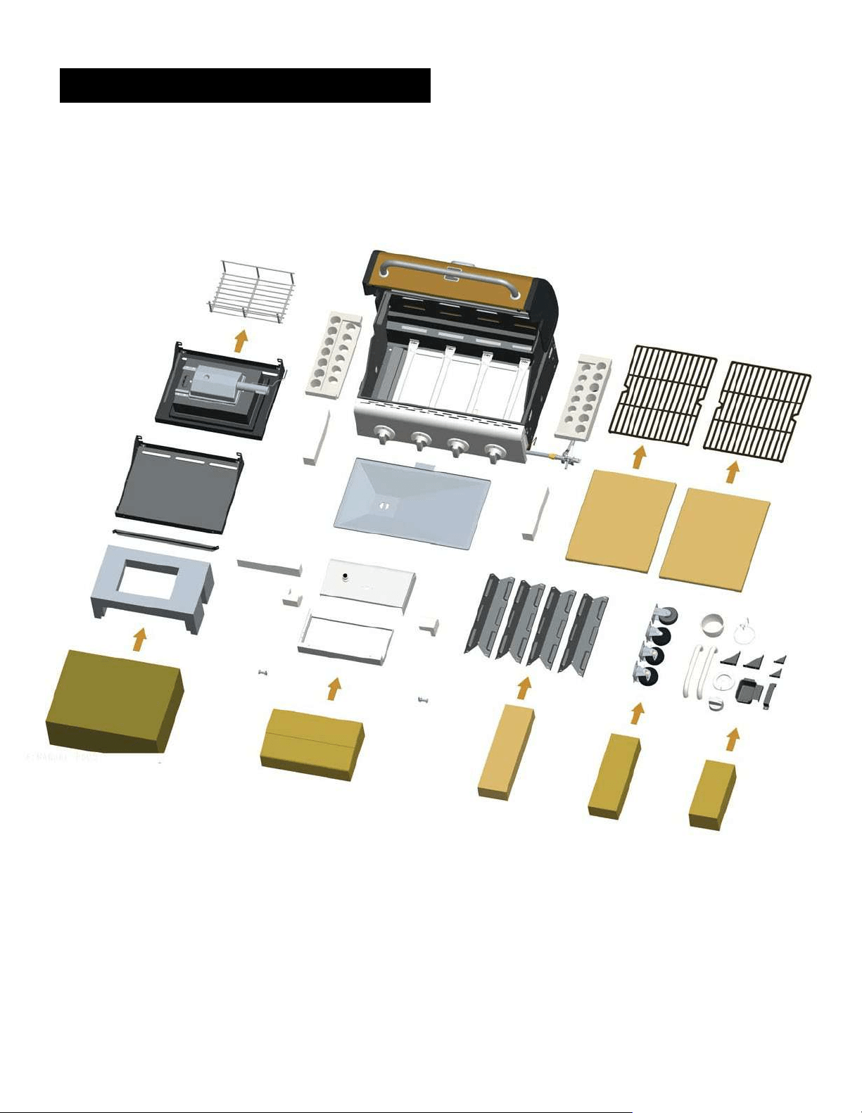
PARTS DIAGRAM

15
BEFORE ASSEMBLY
NOTICE: Once you have unpacked the grill, check all grill parts against the pictures on page 15-1 7.
If any parts are missing or damaged, call 1-888-287-0735.
16
BEFORE ASSEMBLY
17
BEFORE ASSEMBLY
18
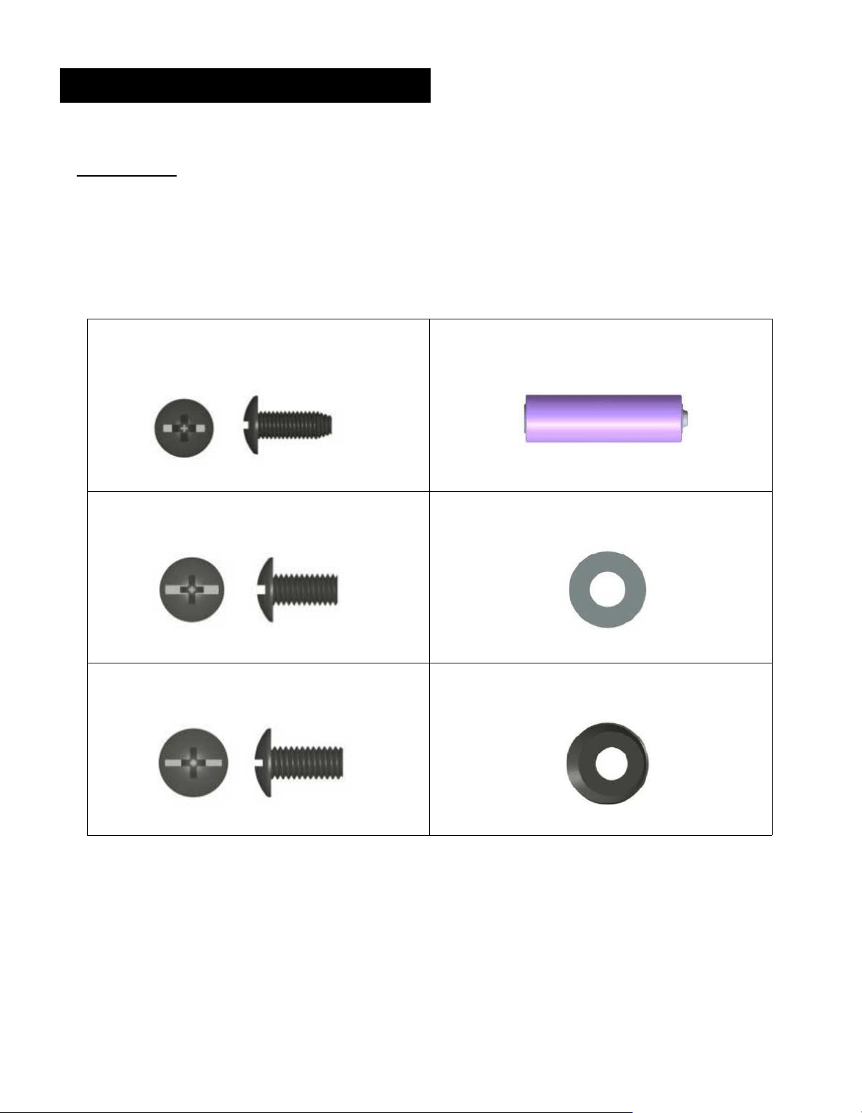
CAREFULLY READ AND PERFORM ALL ASSEMBLY INSTUCTIONS ON THE FOLLOWING PAGES.
Tools Required:
• Adjustable wrench (not provided)
• Screwdriver (not provided)
• The following hardware is provided in the blister pack for convenient use.
ASSEMBLY
M4 x 10 Screw
Qty: 36 pcs
AA Battery
Qty: 1 pc
M5 x 10 Screw
Qty: 4 pcs
M5 Flat Washer
Qty: 4 pcs
M6 x 13 Screw
Qty: 32 pcs
M6 Compression Washer
Qty: 8 pcs
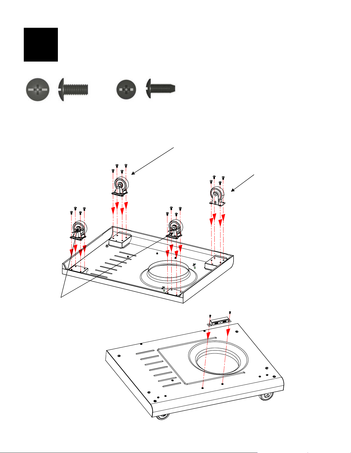
19
Bottom Shelf
Turn the bottom shelf upside down. Attach the casters to the bottom shelf with (16) M6x13 screws.
Note: Install each caster into the correct position as shown in the figure below. The standard caster
(non-swiveling) will only install in one direction.
Turn the bottom shelf right side up. Attach the door magnets to the bottom shelf with (2) M4x10 screws.
M6x13 Screw
Qty: 16 pcs
1
M4x10 Screw
Qty: 2 pcs
Swivel Caster
(Part No.: 40900213)
Standard Caster
(Part No.: 40900214)
Swivel Caster with Brake
(Part No.: 40900212)
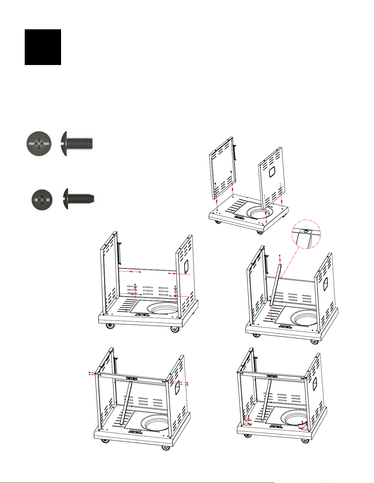
20
Cart
To attach the side panels, align the side panel holes with the leg holes on each side of the bottom shelf.
Note: Left side panel has the match holder attachment.
Attach the left and right side panels to the sides of the bottom shelf with (4) M6x13 screws. (A)
Attach the back panel to the bottom shelf and the two side panels with (6) M4x10 screws. (B)
Attach the tank baffle bar to the back panel and bottom shelf with (2) M4x10 screws. (C)
Align the door bracket holes with the holes on the side panels. Attach the door bracket to the side
panels with (4) M4x10 screws. (D) Note: Attach the bracket so that magnets are on top.
The tank baffle bar will be found underneath the left side shelf (40900515).
Align the holes in the cart support angle bars with the holes on the bottom shelf and the side panels.
Attach the angle bars with (8) M4x10 screws. (E)
2
A
M6x13 Screw
Qty: 4 pcs
M4x10 Screw
Qty: 20 pcs
B
C
D
E
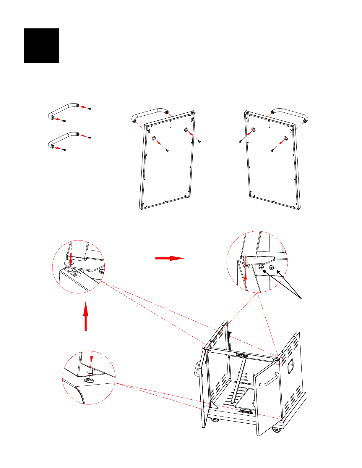
21
Front Door
Remove the (4) M5x15 screws pre-assembled from the door handle ends, and use them to attach the
handles to the doors. (A)
Insert the pin at the bottom of each door into the hole on the bottom panel. Insert the pin at the top of
each door through the hole in the door bracket hinge. (B)
IMPORTANT: If the doors do not line up when closed or do not close freely, the hinges may need to
be adjusted. Loosen the hinge screws, adjust the hinge position as necessary, and retighten the screws.
3
A
B
Hinge Screws
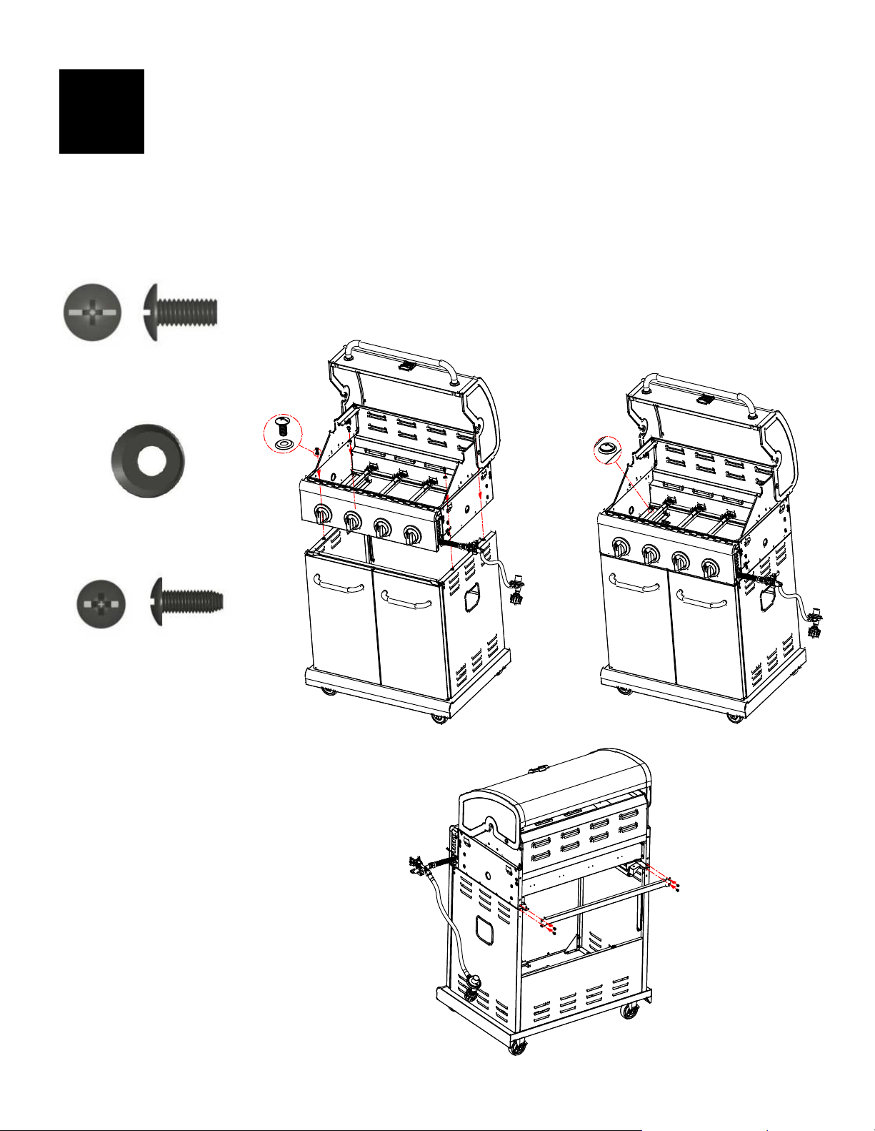
22
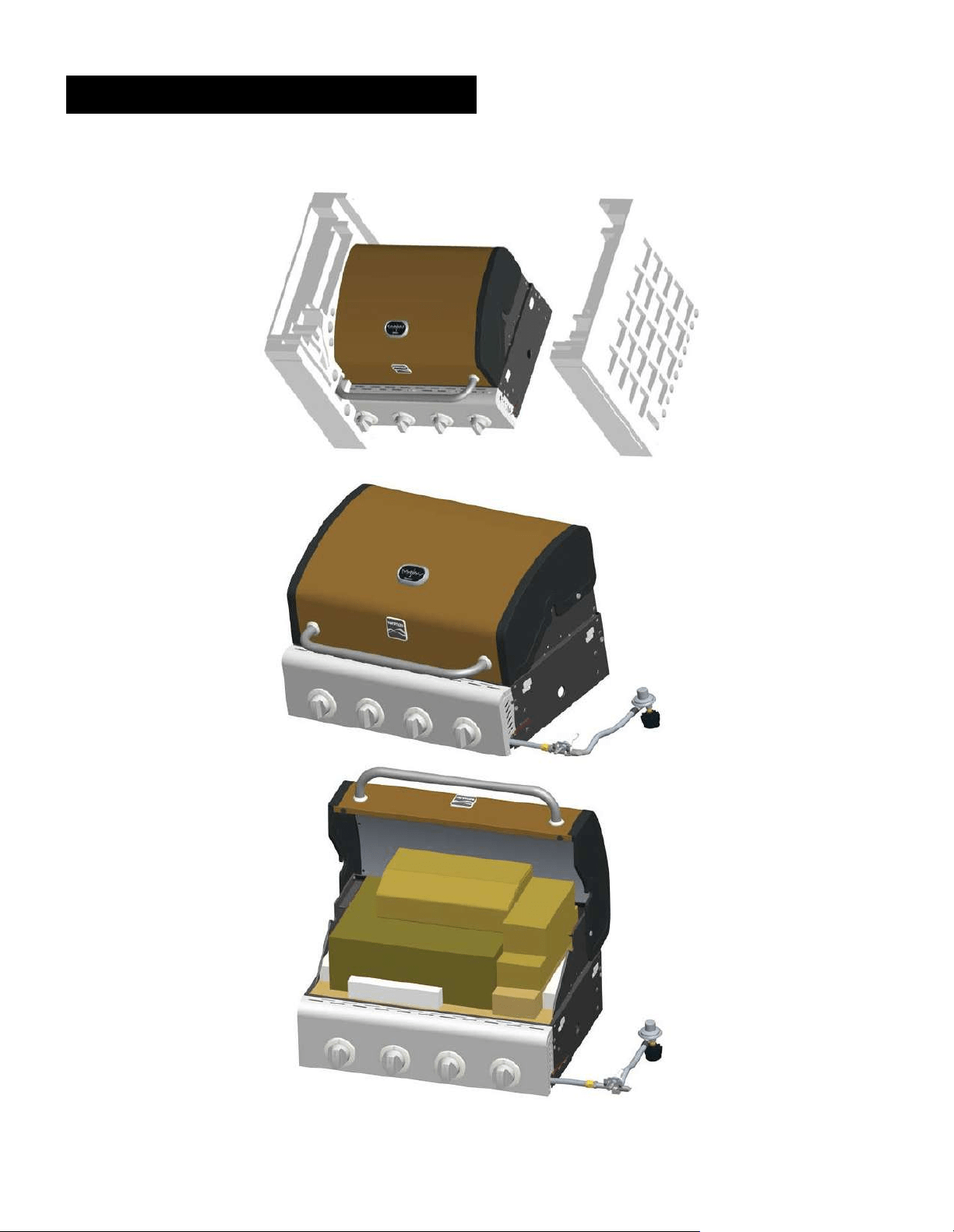
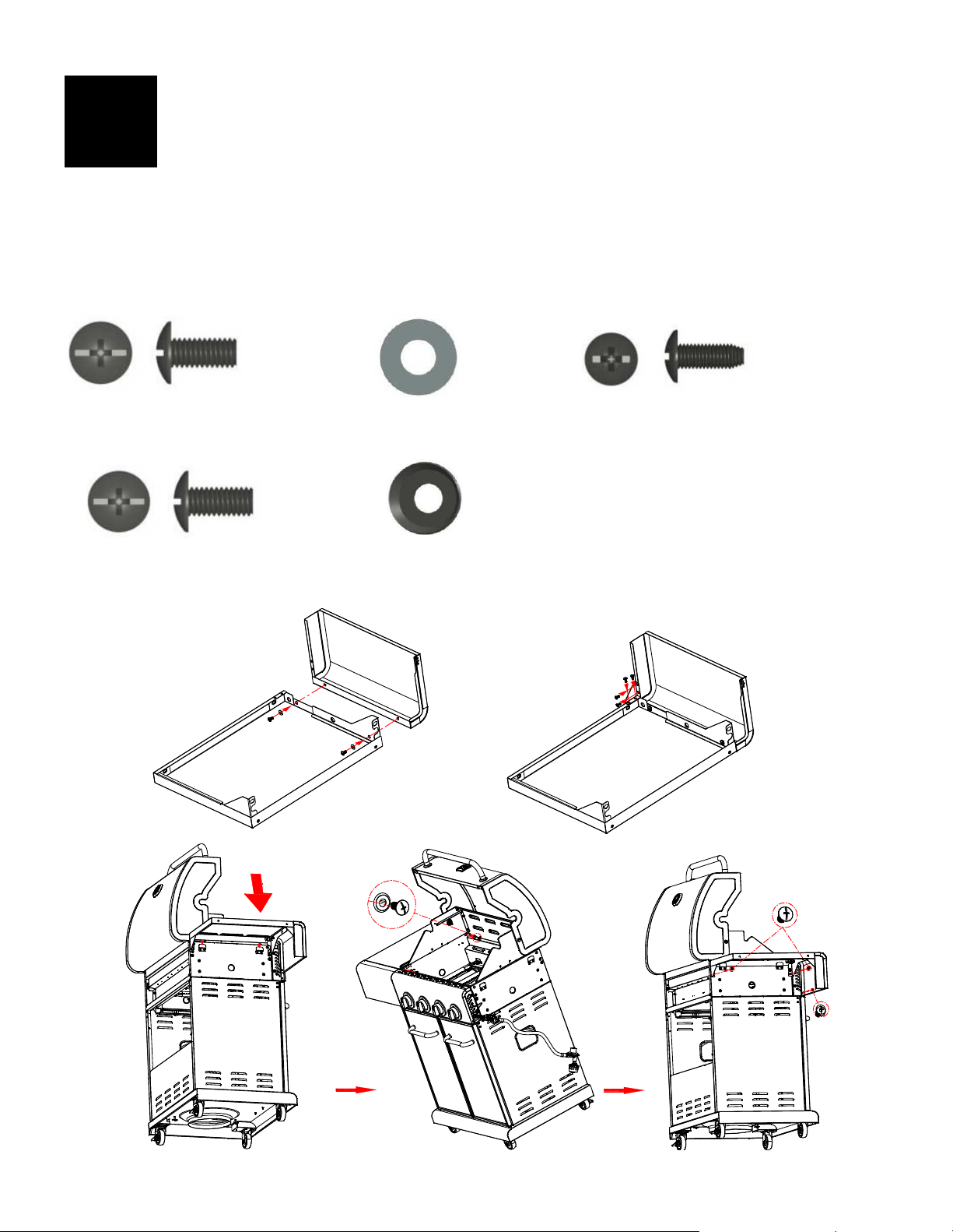
Grill Head to Cart
IMPORTANT: Remove the tie wraps and packing material from the regulator hose, searing burner valve
and igniter wire. Pull the hose and igniter wire out to the right side of the grill head.
This step requires two people to lift and to position the grill head onto the cart.
Carefully lower the grill head onto the cart. Make sure the regulator hose and igniter wire are
hanging outside the cart. Open the lid and attach the head to the cart with(4) M6x13 screws and
M6 compression washers. (A & B)
Align the back rail holes with the holes on the side panels and the firebox. Attach the back rail with
(4) M4x10 screws. (C)
M6x13 Screw
Qty: 4 pcs
4
M4x10 Screw
Qty: 4 pcs
B
C
A
M6 Compression Washer
Qty: 4 pcs
23
Left Side Shelf
Attach the fascia to the left side shelf with (2) M5x10 screws and (2)M5 flat washers. (A)
Attach the shelf support angle bar to the side shelf and fascia with (4) M4x10 screws. (B)
Hang the left side shelf onto the brackets on left side of the firebox. (C)
Attach the shelf to the firebox as follows:
From the inside to the outside of the firebox with (2) M6x13 screws and (2) M6 compression
washers. (D)
IMPORTANT: Be sure the side panel of the firebox and control panel are in alignment before
placing the side shelf.
From the outside to the inside of the firebox with (2) M6x13 screws and (1) M4x10 screw. (E)
M5x10 Screw
Qty: 2 pcs
5
M4x10 Screw
Qty: 5 pcs
M6 Compression Washer
Qty: 2 pcs
M5 Flat Washer
Qty: 2 pcs
M6x13 Screw
Qty: 4 pcs
B
C
A
D
E
24
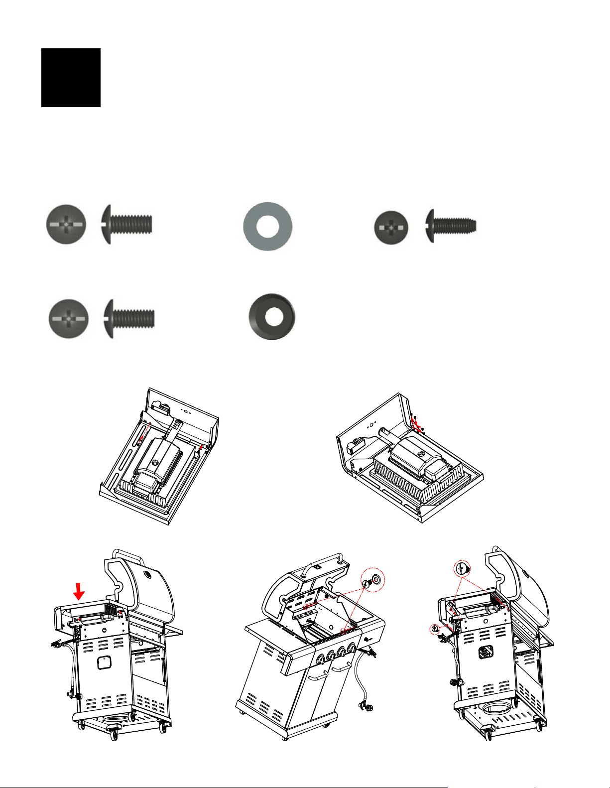
Right Side Shelf
Attach the fascia to the right side shelf with (2) M5x10 screws and (2)M5 flat washers. (A)
Attach the shelf support angle bar to the side shelf and the fascia with (4) M4x10 screws. (B)
Hang the right side shelf onto the brackets on the left side of the firebox. (C)
Attach the shelf to firebox as follows:
From the inside to the outside of the firebox with (2) M6x13 screws and (2) M6 compression
washers. (D)
IMPORTANT: Be sure the side panel of the firebox and control panel are in alignment before
placing the side shelf.
From the outside to the inside of the firebox with (2) M6x13 screws and (1) M4x10 screw. (E)
6
B
C
A
D
E
M5x10 Screw
Qty: 2 pcs
M4x10 Screw
Qty: 5 pcs
M6 Compression Washer
Qty: 2 pcs
M5 Flat Washer
Qty: 2 pcs
M6x13 Screw
Qty: 4 pcs
25
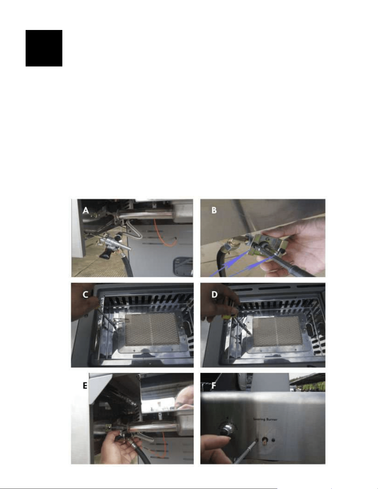
Searing Burner
Remove the plastic packaging from the searing burner valve. Remove the searing burner grate from the
searing burner shelf.
Remove the 2 pre-installed screws from the valve control stem and set them aside. (A & B)
Loosen the searing burner to insert the gas valve. First, loosen and remove the screw attaching the
electrode (C) to the shelf and set it aside, then loosen and remove the 2 screws holding the searing burner
in place. (D)
Insert the gas valve into the searing burner. (E) Insert the valve control stem through the hole in the fascia.
(F) Install the 2 previously removed valve control stem screws, but do not fully tighten until the bezel has
been attached to the fascia.
Reattach the searing burner to the shelf with the 2 previously removed screws. (G)
Reattach the electrode to the shelf with the previously removed screw from the searing burner. (H)
Insert the bezel openings over the valve control stem and the 2 screws. (I)
Slide the bezel down onto the screws. Make sure that the black mark on bezel is vertical.
Tighten the 2 screws to secure the bezel to the fascia. (J)
Push the control knob onto searing burner valve stem. (K)
Place back the searing burner grid. (L)
Connect both igniter wires to the igniter module on the left side of the searing burner shelf fascia.
To connect, push the igniter wire tips into the slots on the pins in igniter module. (M)
Slide the searing burner drip box into the drip box bracket. (N)
Unscrew the igniter cap from the control panel. Insert (1) AA battery (provided in the blister pack) into the
battery slot with the positive end (+) facing outward. Screw the igniter cap back onto the fascia. (O)
7

26
27
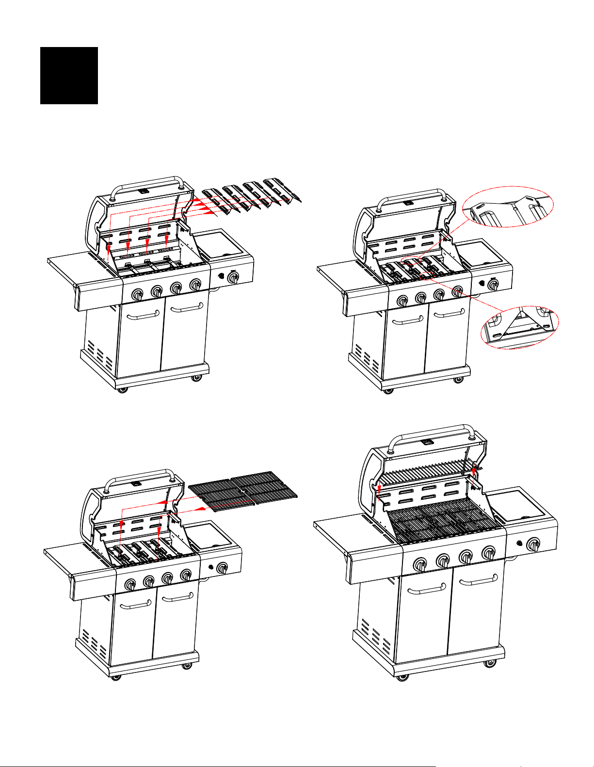
Heat Diffuser, Cooking Grates and Warming Rack
Place the heat diffusers over the burners. Diffusers will fit in the firebox in either direction. Fit the tabs in
the firebox's front end through the slots in the diffuser's tips. Fit the diffuser's tips in between the tabs in
the firebox's rear end. (A & B)
Place the cooking grates onto the grate rests at the front and rear of the firebox. (C)
Insert the warming rack into the brackets at the top of the firebox with the upcurved edge in the front
as shown. (D)
8
B
C
A
D
28
Drip Tray, Drip Cup and LP Tank
Slide the drip tray into the bottom of the firebox from the back. (A)
Hang the drip cup clip from the bottom of the drip tray. Make sure the drip drainage hole is on the
right side, as seen from the back of the grill. Place the drip cup into the drip cup clip. (B)
Feed the regulator hose through the hole in the right side panel. (C)
LP tank is sold separately. Use only with an OPD (Overfill Protection Device) equipped LP tank.
Fill and leak check before attaching to grill and regulator.
Place the LP tank into the hole on the bottom shelf with the tank collar opening facing to the right as
shown. Raise the tank holder to hold the LP tank securely in place. (C)
When the grill is in the desired location, lock the caster brakes; this will help the grill stay in place for
safe operation. (D)
9
Failure to install the drip cup and the drip
cup clip will cause hot fall into the bottom
of the grill with a risk of fire and property
damage.
CAUTION
CAUTION
Failure to install the tank correctly may
allow the gas hose to be damaged
during operation.
B
C
A
D
29
EMERGENCIES: If a gas leak cannot be stopped, or a fire occurs due to gas leakage, call the fire department.
Problem Possible Cause Prevention/Solution
Gas leaking from
cracked/cut/burned a
hose.
Gas leaking from the LP
tank.
Gas leaking from the LP
tank valve.
Gas leaking between the
LP tank and the regulator
connection.
Fire coming through the
control panel.
Drip fire or continuous
excessive flames above
the cooking surface.
• Damaged hose.
• Mechanical failure due to rusting or
mishandling.
• Failure of the tank valve through
mishandling or mechanical failure.
• Improper installation, connection not
being tight, or failure of the rubber
seal.
• Fire in the burner tube section due to
blockage.
• Too much drip buildup in firebox or
grease tray area.
• Turn off the gas from your LP tank or your natural gas system.
If the hose is cracked or cut but not burned, simply replace the
valve / hose / regulator. If the hose is burned, the cause could
be something other than a faulty valve/hose/regulator. Do not
use of grill until a plumber or gas technician has investigated
and corrected the problem.
• Replace the LP tank.
• Turn off the LP tank valve. Return the LP tank to the gas supplier.
• Turn off the LP tank valve. Remove the regulator from the tank
and visually inspect the rubber seal for any damage. See the
Leak test on page 7 for instructions on finding leaks in your
regulator.
• Turn the control knobs and the LP tank valve off. Leave the lid
open to allow the flames to die down. After the fire is out and
the grill is cold, remove the burner and inspect for spider nests
or rust. See the Spider Alert and Cleaning the Burner Assembly
sections on page 10 of this Use & Care Guide.
• Turn the control knobs and LP tank valve off. Leave the lid open
to allow the flames to die down. After the grill has cooled, clean
any food particles and excess Drip from inside the firebox area,
grease tray, and any other surface that may come into contact
with food particles and excess Drip.
Problem Possible Cause Prevention/Solution
Burner(s) will not light
using the igniter. (Also
view the Electronic ignition
Troubleshooting)
Continued on next page.
GAS ISSUES:
• Trying to light the wrong burner.
• Burner is not engaged with the
control valve.
• Obstruction in the burner.
• No gas flow.
• Coupling nut and LP tank valve not
fully connected.
ELECTRICAL ISSUES:
• Electrode cracked or broken;
sparks at crack.
• Electrode tip is not in the proper
position.
• Wire and/or electrode covered
with cooking residue.
• Wires are loose or disconnected.
• Wires are shorting (sparking)
between igniter and electrode.
• Dead battery.
• See instructions on the control panel and in the Use and Care
section.
• Make sure the valves are positioned inside of the burner tubes.
•
Ensure the burner tubes are not obstructed with spider webs or
other matter. See the cleaning section on page 10 of the Use
and Care.
• Make sure the LP tank is not empty. If the LP tank is not empty,
refer to the “Sudden drop in gas flow section on page 30”.
• Turn off the knobs and disconnect the coupling nut from LP tank.
Reconnect and retry.
• Turn the coupling nut approximately one-half to three-quarters
additional turn until solid stop. Tighten by hand only - do not use
tools.
• Replace the electrode(s).
Main Burners:
• Tips of the electrode should be pointing toward the gas port
opening on the burner. The distance should be 1/8” to 1/4”.
Adjust if necessary.
Side Burner:
• Tip of the electrode should be pointing toward the gas port
opening on the burner. The distance should be 1/8” to 3/16”.
Adjust if necessary.
• Clean the wire and/or electrode with rubbing alcohol with a
clean swab.
• Reconnect the wires or replace the electrode/wire assembly.
• Replace with a new AA-size alkaline battery.
Troubleshooting

30
Troubleshooting (continued)
Problem
Possible Cause
Prevention/Solution
Burner(s) will not light
using igniter.
(Also view the
Electronic ignition
Troubleshooting.)
ELECTRONIC IGNITION:
• No spark, no ignition noise.
• No spark, some ignition noise.
• Sparks, but not at the electrode
or at full strength.
• See Section I of the Electronic Ignition System.
• See Section II of the Electronic Ignition System.
• See Section III of the Electronic Ignition System.
Burner(s) will not light
with match.
• See “GAS ISSUES:” on the
previous page.
• Match will not reach.
• Improper method of match-
lighting.
• Use a long-stem match (fireplace match).
• See “Match-Lighting” section on page 9 of the Use and
Care.
Sudden drop in gas flow
or low flame.
• Out of gas.
• Excess flow valve tripped.
• Vapor lock at the coupling
nut/LP tank connection.
• Check for gas in the LP tank.
• Turn off the knobs, wait 30 seconds and light the grill. If
the flames are still low, turn off the knobs and LP tank
valve. Disconnect the regulator. Reconnect the regulator
and perform a leak-test. Turn on the LP tank valve, wait 30
seconds and then light the grill.
• Turn off the knobs and the LP tank valve. Disconnect the
coupling nut from the tank. Reconnect and retry.
Flames blow out. • High or gusting winds.
• Low on LP gas.
• Excess flow valve tripped.
• Turn the grill so that the front of the grill faces the wind or
increase the flame height.
• Refill the LP tank.
• Refer to the “Sudden drop in gas flow” section above.
Flare-up. • Drip buildup.
• Excessive fat in meat.
• Excessive cooking temperature.
• Clean the burners and the inside of the grill/firebox.
• Trim the fat from the meat before grilling.
• Adjust to a lower temperature.
Persistent drip fire. • Drip trapped by food buildup
around the burner system.
• Turn the knobs to OFF. Turn the gas in the LP tank off.
Leave the lid in position and let the fire burn out. After the
grill cools, remove and clean all parts.
Flashback… (fire in
burner tube(s)).
• Burner and/or burner tubes are
blocked.
• Turn the knobs to OFF. Clean the burner and/or burner
tubes. See the burner cleaning section on page 10 of the
Use and Care.
Unable to fill the LP tank. • Some dealers have older fill
nozzles with worn threads.
• The worn nozzles don’t have enough “bite” to engage the
valve. Try a second LP dealer.
One burner does not
light from other
burner(s).
• Drip buildup or food particles in
the end(s of carryover tube(s).
• Clean the carry-over tube(s) with a wire brush.

31
Troubleshooting – Electronic Ignition
Problem Possible Cause Check Item Prevention/Solution
SECTION I
No sparks appear
at any electrodes
when control knob
are turned to HI:
no noise can be
heard from the
spark module.
• The battery is not
installed properly.
• Dead battery.
• The wire assembly
is not installed
properly.
• Faulty spark
module.
• Check that the battery
has the positive side
facing the outside.
• Has the battery been
used previously?
• Check to ensure the
threads are properly
engaged.
• If no sparks are
generated with the new
battery and the wires are
connected properly, the
module is faulty.
• Install the battery, making sure that the
positive end is facing outward, and the
negative end is facing inward.
• Replace the battery with a new AA-size
alkaline battery.
• Unscrew the ignition module assembly and
be sure that all the wires are installed
properly before reinstalling the ignition
module assembly.
• Replace the ignition module assembly by
calling customer service at 1-888-287-0735.
SECTION II
No sparks appear
at any electrodes
when control knob
is turned to HI;
noise can be
heard from the
spark module.
• The Electrodes are
not connected
properly.
• Are the electrodes tightly
connected?
• Remove and reconnect all electrode wires
from the module sockets.
SECTION III
Sparks are
present but not at
all electrodes
and/or not at full
strength.
• The electrodes are
not connected
properly.
• Electrical arc
between the output
wires and burner
tube.
• Weak battery.
• Electrodes are wet.
• The electrode(s)
are cracked or
broken; sparks
appear where
cracked.
• Are the electrodes tightly
connected?
• If possible, observe grill a
in dark location. Operate
the ignition system and
look for arcing between
the output wires and
burner tube.
• All sparks are present but
have a weak or slow
rate.
• Has moisture
accumulated on the
electrode and/or in
burner ports?
• Inspect the electrodes
for cracks.
• Remove and reconnect all electrode wires
from the module sockets.
• If sparks are seen in places other than the
burner tube area, the wire insulation may be
damaged. Replace wires.
• Replace the battery with a new AA-size
alkaline battery.
• Use a paper towel to remove any moisture.
• Replace the cracked or broken electrodes
by calling customer service at 1-888-287-
0735.
SECTION IV
Grill is not getting
hot and is only
reaching 250 –
300 degrees
• This typically
occurs when you
turn on your control
knobs before you
turn on the LP tank
valve. If so, this will
activate the gas
regulator safety
device, the grill will
only reach
temperatures
between 250 and
300F even with all
burners on the high
setting.
• Are the regulator on and
tight?
• Make sure the regulator
is connected properly to
the tank, and control
knobs are all in the off
position.
• Open the grill lid.
• Turn off all knobs on the control panel.
• Turn off the tank knob.
• Disconnect the regulator from the LP tank.
Wait 30 seconds.
• Reconnect the regulator to the LP tank.
• Slowly open the LP tank knob all the way.
Do not put excessive force on the valve
when in the fully open position to avoid
damaging the valve.
• Turn on the appropriate control knob and
light the grill per the lighting instructions on
page 9.
TABLA DE CONTENIDO
32
ADVERTENCIA
La combustión de los productos producidos al
usar este producto incluye monóxido de carbono,
un químico conocido en el Estado de California
como causante de defectos de nacimiento u otros
daños reproductivos. Para obtener más
información, visite www.P65Warnings.ca.gov
Por su propia seguridad . . . . . . . . . . . . . . . . . . . . . . . . . . . . . . . . . . . . . . . . . . . . . . . . . . . . . . . . . . . . . . .
Centro de servicio para parrillas . . . . . . . . . . . . . . . . . . . . . . . . . . . . . . . . . . . . . . . . . . . . . . . . . . . . . . .
Información de inscripción de la garantía . . . . . . . . . . . . . . . . . . . . . . . . . . . . . . . . . . . . . . . . . . . . . . .
Símbolos de seguridad . . . . . . . . . . . . . . . . . . . . . . . . . . . . . . . . . . . . . . . . . . . . . . . . . . . . . . . . . . . . . . . .
Medidas de seguridad para la instalación . . . . . . . . . . . . . . . . . . . . . . . . . . . . . . . . . . . . . . . . . . . . . . .
Garantía para la parrilla Kenmore . . . . . . . . . . . . . . . . . . . . . . . . . . . . . . . . . . . . . . . . . . . . . . . . . . . . .
Uso y mantenimiento . . . . . . . . . . . . . . . . . . . . . . . . . . . . . . . . . . . . . . . . . . . . . . . . . . . . . . . . . . . . . . .
Lista de piezas . . . . . . . . . . . . . . . . . . . . . . . . . . . . . . . . . . . . . . . . . . . . . . . . . . . . . . . . . . . . . . . . . . . .
Vista esquemática de las piezas . . . . . . . . . . . . . . . . . . . . . . . . . . . . . . . . . . . . . . . . . . . . . . . . . . . . . . . .
Armado . . . . . . . . . . . . . . . . . . . . . . . . . . . . . . . . . . . . . . . . . . . . . . . . . . . . . . . . . . . . . . . . . . . . . . . . . .
Antes De La Asamblea . . . . . . . . . . . . . . . . . . . . . . . . . . . . . . . . . . . . . . . . . . . . . . . . . . . . . . . . . . . . .
Resolución de problemas . . . . . . . . . . . . . . . . . . . . . . . . . . . . . . . . . . . . . . . . . . . . . . . . . . . . . . . . . . .
33
33
33
33
33
34
35-41
42-43
44
45-47
48-58
59-61
Si siente olor a gas :
Póngase en contacto con el servicio al cliente
de permasteel para obtener ayuda y piezas
Inscripción del producto
IMPORTANTE: Llene la siguiente información.
Número de modelo ___________________________
Número de serie _____________________________
El número de serie se encuentra en la
etiqueta de especificaciones de la parrilla.
Fecha de compra _____________________________
PELIGRO
ADVERTENCIA
1. No guarde ni use gasolina ni otros líquidos
o gases inflamables cerca de éste ni de
cualquier otro aparato.
2. No guarde un tanque de gas propano, que
no esté conectado, cerca de éste ni de
cualquier otro aparato.
Sólo para uso residencial. No utilice
para la cocina comercial.
PRECAUCIÓN
PRECAUCIÓN: una situación potencialmente
peligrosa o una practica insegura que, si no se evita,
podría resultar en lesiones menores o moderadas.
PRECAUCIÓN
ADVERTENCIA: Indica una situación
potencialmente peligrosa que, si no se evita, podría
resultar en lesiones graves o la muerte.
ADVERTENCIA
PELIGRO: Indica una situación inminentemente peligrosa
que, si no se evita, resultará en muerte o lesiones graves.
PELIGRO
Precauciones de instalación
• Por favor lea este Manual del usuario en su totalidad antes de
usar la parrilla.
• El incumplimiento de la instrucción proporcionada puede
resultar en lesiones graves o daños a la propiedad.
• Algunas partes de esta parrilla pueden tener bordes afilados.
Por favor, utilice guantes de protección adecuados.
• Parrilla de uso, como compró, únicamente con propano gas y
theregulator/válvula suministrada.
• Parrilla de instalación debe cumplir con los códigos locales, o
en su ausencia de códigos locales, ya sea con el código
nacional de Gas combustible, ANSI Z223.1 / NFPA 54, Gas
Natural y propano instalación código, CSA B149.1, o
almacenaje de propano y código de manipulación, B149.2 o la
norma para vehículos recreativos, ANSI una 119.2/NFPA 1192 y
CSA Z240 RV Series, código de vehículo recreativo, según sea
el caso.
• Todos los accesorios eléctricos (como soporte) deben ser
eléctricamente puesta a tierra según los códigos locales, o el
código eléctrico nacional, ANSI / NFPA 70 o código eléctrico
canadiense CSA C22.1. Mantenga cualquier cables eléctricos o
mangueras de suministro de combustible de cualquier superficie
caliente.
• Esta parrilla es seguridad certificado para su uso en los Estados
Unidos y Canadá solamente. No modifique para el uso en
cualquier otro lugar. La modificación puede resultar en un
peligro para la seguridad y anulará la garantía de esta parrilla.
1. 1. Cierre el paso de gas al aparato.
2. Apague toda llama al descubierto.
3. Abra la tapa.
4. Si persiste el olor, aléjese del aparato y
llame inmediatamente al proveedor local de
gas o a los bomberos.
O visítenos en Kenmoregrill.com
Si tiene alguna pregunta o necesita ayuda durante el
montaje, por favor llame al
1-888-287-0735. M - F 8:00 a. m.
a 5:00 p. m. hora estándar del Pacífico. Usted hablará con el
representante del fabricante de la parrilla.
Símbolos de seguridad
Los símbolos y las cajas que se muestra a continuación explicaron
lo que significa cada línea. Lea y siga todos los mensajes que se
encuentran en el manual de.
IMPORTANTE: Esta parrilla está diseñada para uso al aire libre
solamente y no pretende instalarse en o en remolques o barcos.
33
NOTA PARA EL INSTALADOR: Deje este Manual con el cliente
después de la entrega o instalación.
NOTA AL CONSUMIDOR: Deje este Manual en un lugar
conveniente para referencia futura.

34
GARANTÍA
GARANTÍA LIMITADA DE KENMORE
CON LA PRUEBA DE VENTA: se aplica la siguiente cobertura de garantía cuando este dispositivo se instala, opera y
mantiene correctamente de acuerdo con todas las instrucciones suministradas. Nota: El consumidor es responsable del envío
y manejo de todas las piezas de repuesto bajo garantía.
POR UN AÑO: a partir de la fecha de venta, esta parrilla está garantizada contra defectos en materiales o mano de obra,
el consumidor recibirá piezas de repuesto gratis con el comprobante de compra, el consumidor es responsable del costo
de S&H.
Toda la cobertura de la garantía excluye las baterías de ignición y la pérdida de pintura, decoloración o corrosión de la
parte de la parrilla, que son piezas fungibles que pueden desgastarse debido al uso normal dentro del período de garantía,
o son condiciones que pueden ser el resultado de un uso normal, accidente o mantenimiento inadecuado . Toda la
cobertura de la garantía se anulará si este aparato se utiliza para fines distintos de los domésticos. Para obtener detalles
de la cobertura de la garantía para obtener piezas de repuesto, visite la página web:
Kenmoregrill.com
Esta garantía cubre SOLO defectos en materiales y mano de obra, y NO pagará por:
1. Llamadas de servicio para corregir la instalación de electrodomésticos o para reparar problemas con fusibles
domésticos, disyuntores, cableado y sistemas de plomería o suministro de gas resultantes de dicha instalación.
2. Servicio a un electrodoméstico si el modelo y la placa de serie faltan, están alterados o no se puede determinar
fácilmente que tienen el logotipo de certificación apropiado.
3. Artículos consumibles que pueden desgastarse por el uso normal dentro del período de garantía, incluidos, entre otros,
pilas, bombillas de base atornillable y revestimientos o acabados de superficies.
4. Un técnico de servicio para limpiar o mantener este aparato, o para instruir al usuario en la instalación correcta del
aparato, operación y mantenimiento.
5. Daño o falla de este electrodoméstico como resultado de la instalación, incluida la instalación que no estuvo de
acuerdo con códigos de electricidad, gas o plomería.
6. Daño o falla de este aparato, incluyendo decoloración o oxidación de la superficie, si no se opera correctamente y
mantenido de acuerdo con todas las instrucciones suministradas.
7. Daño o falla de este electrodoméstico, incluida la decoloración o oxidación de la superficie, como resultado de un
accidente, alteración, abuso, mal uso o uso para fines distintos a los previstos.
8. Daños o fallas de este electrodoméstico, incluida la decoloración o oxidación de la superficie, causados por el uso de
detergentes, limpiadores, productos químicos o utensilios que no sean los recomendados en todas las instrucciones
proporcionadas con el producto.
9. Daños o fallas de este electrodoméstico como resultado de una catástrofe natural o de otro tipo, como inundaciones,
incendios o tormentas.
10. Daño o falla de piezas o sistemas como resultado de modificaciones no autorizadas realizadas a este aparato.
Descargo de responsabilidad de las garantías implícitas; limitación de remedios.
El único y exclusivo remedio del cliente bajo esta garantía limitada será la reparación o el reemplazo del producto según
lo dispuesto en el presente docmento. Las garantías implícitas, incluidas las garantías de comerciabilidad o adecuación
para un propósito particular, están limitadas a un año en el aparato, y cinco años en los quemadores, o el período más
corto permitido por la ley. El vendedor no será responsable por daños incidentales o consecuentes. Algunos estados y
provincias no permiten la exclusión o limitación de daños incidentales o consecuentes, o la limitación en la duración de las
garantías implícitas de comercialización o adecuación, por lo que estas exclusiones o limitaciones pueden no aplicarse a
usted.
Esta garantía le otorga derechos legales específicos, y también puede tener otros derechos que varían de un estado a otro.
POR CINCO AÑOS: a partir de la fecha de venta, se reemplazará cualquier quemador de acero inoxidable que se corra
o se queme, se debe proporcionar un comprobante de compra, el consumidor es responsable del costo de envío y manejo.
Producto distribuido por Permasteel, 100 Exchange Place, Pomona, CA 91768. Hecho en china.
35
UOS Y MANTENIMIENTO
• NUNCA guarde un cilindro de gas de repuesto
debajo o cerca del aparato o en un areacerrada.
PELIGRO
• Nunca llene un tanque más allá del 80 %
completo.
• Si la información en los dos puntos anteriores no
se siguen exactamente, un incendio causando la
muerte o pueden producir lesiones graves.
• Un cilindro de un llenado excesivo o mal
almacenado es un peligro debido a la liberación
de gas posible de la válvula de seguridad. Esto
podría causar un fuego intenso con riesgo de
daños a la propiedad, lesiones graves o la
muerte.
• Si usted observa, huele o escucha gas escapar,
alejarse del cilindro de gas LP y el artefacto
inmediatamente y llame a los bomberos.
Remoción, transporte y almacenamiento del tanque
de gas propano
• APAGUE todas las perillas de control y la válvula del
tanque de PL. Gire la tuerca de acoplamiento en sentido
contrario a las agujas del reloj solo con la mano; no use
herramientas para desconectar. Levante la correa de
retención del tanque de LP hacia arriba del collar del
tanque de LP, luego levante el tanque de LP y sáquelo del
soporte. Instale la tapa de seguridad en la válvula del
tanque de LP. Utilice siempre la tapa y la correa
suministradas con la válvula.
No usar el tapón de seguridad según las instrucciones
puede resultar en lesiones personales graves y/o
daños a la propiedad.
• Un tanque de LP desconectado en almacenamiento o un
tanque de LP que se transporta debe tener una tapa de
seguridad instalada (como se muestra). No almacene un
tanque de LP en espacios cerrados como una cochera,
garaje, porche, patio cubierto u otros edificios. Nunca
deje un tanque de LP dentro de un vehículo que pueda
sobrecalentarse con el sol.
• No almacene un tanque de LP en un área donde jueguen
los niños.
Válvula de
tanque LP
Tapa de
seguridad
Correa de retención
•
El tanque de LP que se usa con su parrilla debe cumplir con
los siguientes requisitos:
• Use el tanque de LP solo con estas medidas requeridas: 12"
(30,5 cm) (diámetro) x 18" (45,7 cm) (alto) con una
capacidad máxima de 20 lb (9 kg).
• El tanque de LP debe construirse y marcarse de acuerdo
con las especificaciones para tanques de LP del
Departamento de Transporte (DOT) de EE. UU. o para
Canadá, CAN/CSA-B339, tanques, esferas y tubos para el
transporte de mercancías peligrosas. Transporte Canadá
(TC). Consulte el cuello del tanque de LP para ver las
marcas.
• La válvula del tanque de LP debe tener:
• El tanque de LP debe estar preparado para la extracción
de vapor e incluir un collar para proteger la válvula del
tanque de LP. Siempre mantenga los tanques de LP en
posición vertical durante el uso, tránsito o almacenamiento.
• Salida tipo 1 compatible con
regulador o grill.
• Valvula de seguridad.
•
Dispositivo de protección contra
sobrellenado (OPD) listado en UL.
Esta característica de seguridad
del OPD se identifica mediante un
volante triangular exclusivo.
Utilice únicamente tanques de LP equipados con este
tipo de válvula.
LP (Gas Liquido de Petróleo)
• El gas LP no es tóxico, es inodoro e incoloro cuando se
produce.
Para su seguridad, al gas LP se le ha dado un olor
(similar al repollo podrido) para que pueda olerlo.
• El gas LP es altamente inflamable y puede encenderse
inesperadamente cuando se mezcla con aire.
Llenado de tanques de LP
• Use solo distribuidores autorizados y experimentados.
• El distribuidor de LP debe purgar el tanque nuevo antes de
llenarlo.
• El distribuidor NUNCA debe llenar el tanque de LP más del
80 % del volumen del tanque de LP. El volumen de propano
en el cilindro variará según la temperatura
.
• Un regulador helado indica sobrellenado de gas. Cierre
inmediatamente la válvula del tanque de LP y llame a su
distribuidor local de gas LP para obtener ayuda.
• No libere el gas propano líquido (LP) a la atmósfera. Esta es
una práctica peligrosa.
• Para retirar el gas del tanque de LP, comuníquese con un
distribuidor de LP o llame al departamento de bomberos
local para obtener ayuda. Consulte el directorio telefónico
en "Compañías de gas" para conocer los distribuidores
certificados de LP más cercanos.
Tanque de LP en posición vertical para extracción de vapor
Tanque de LP
Rueda de
mano OPD
36
Como conectar el regulador al tanque de gas
propano
1. El tanque del LP se debe asegurar correctamente sobre
parrilla. (Refiera a la sección de la asamblea.)
2. Dé vuelta a todas las perillas de control a la posición de
reposo.
3. Dé vuelta al tanque del LP APAGADO dando vuelta al
manubrio de OPD a la derecha a una parada completa.
4. Quite la tapa protectora de la válvula del tanque del LP.
Utilice siempre el casquillo y la correa proveídos de la
válvula.
No utilice agentes de limpieza domésticos. El uso de
agentes de limpieza puede dañar los componentes del
tren de gas (válvula/manguera/regulador).
El manguito de unión
debe quedar centrado
en la válvula del
tanque de gas.
5. Sostenga el regulador e inserte la
boquilla en la válvula del tanque
de LP. Apriete a mano la tuerca de
acoplamiento, sujetando el
regulador en línea recta con la
válvula del tanque de LP para no
cruzar la rosca de la conexión.
Cambio del tanque de gas
• Muchos minoristas de propano ofrecen la opción de
reemplazar su tanque de LP vacío a través de un servicio
de intercambio. Utilice únicamente empresas de
intercambio acreditadas que inspeccionen, llenen con
precisión, prueben y certifiquen sus cilindros.
Cambie su
tanque sólo por otros tanques equipados con el
dispositivo de seguridad volumétrica que se describe en
la sección de Tanques de gas de este manual.
• Mantenga siempre sus tanques LP nuevos y cambiados en
posición vertical durante el uso, el transporte o el
almacenamiento.
• Verifique que los tanques de gas, nuevos o de recambio,
no tengan fugas ANTES de conectarlos a la parrilla.
Prueba para detectar fugas del tanque de gas propano
• La prueba de escape debe ser repetida cada vez que se
intercambia o se rellena el tanque del LP.
• No fume durante prueba de escape.
• No utilice una llama abierta a la comprobación para
escapes del gas.
• La parrilla debe someterse a una prueba de fugas al aire
libre en un área bien ventilada, lejos de fuentes de
ignición como gas o aparatos eléctricos. Durante la
prueba de fugas, mantenga la parrilla alejada de llamas
abiertas o chispas.
• Utilice una brocha limpia y solución una 50/50 suave del
jabón y del agua. Cepille la solución jabonosa sobre las
áreas indicadas por las flechas en figura abajo. Los
escapes son indicados creciendo burbujas.
Por su propia su seguridad:
ADVERTENCIA
Si aparecen burbujas “crecientes”, no use ni mueva
el tanque de LP. ¡Comuníquese con un proveedor
de gas LP o con su departamento de bomberos!
Válvula de
seguridad
Tira y tapa
Salida tipo 1,
con rosca
exterior
Rueda de
mano OPD
No use un tapón POL para
transporte (la pieza de
plástico con roscas en el
exterior). Eliminará la
función de válvula de alivio
de seguridad.
(APAGADO En el sentido de las agujas del reloj)
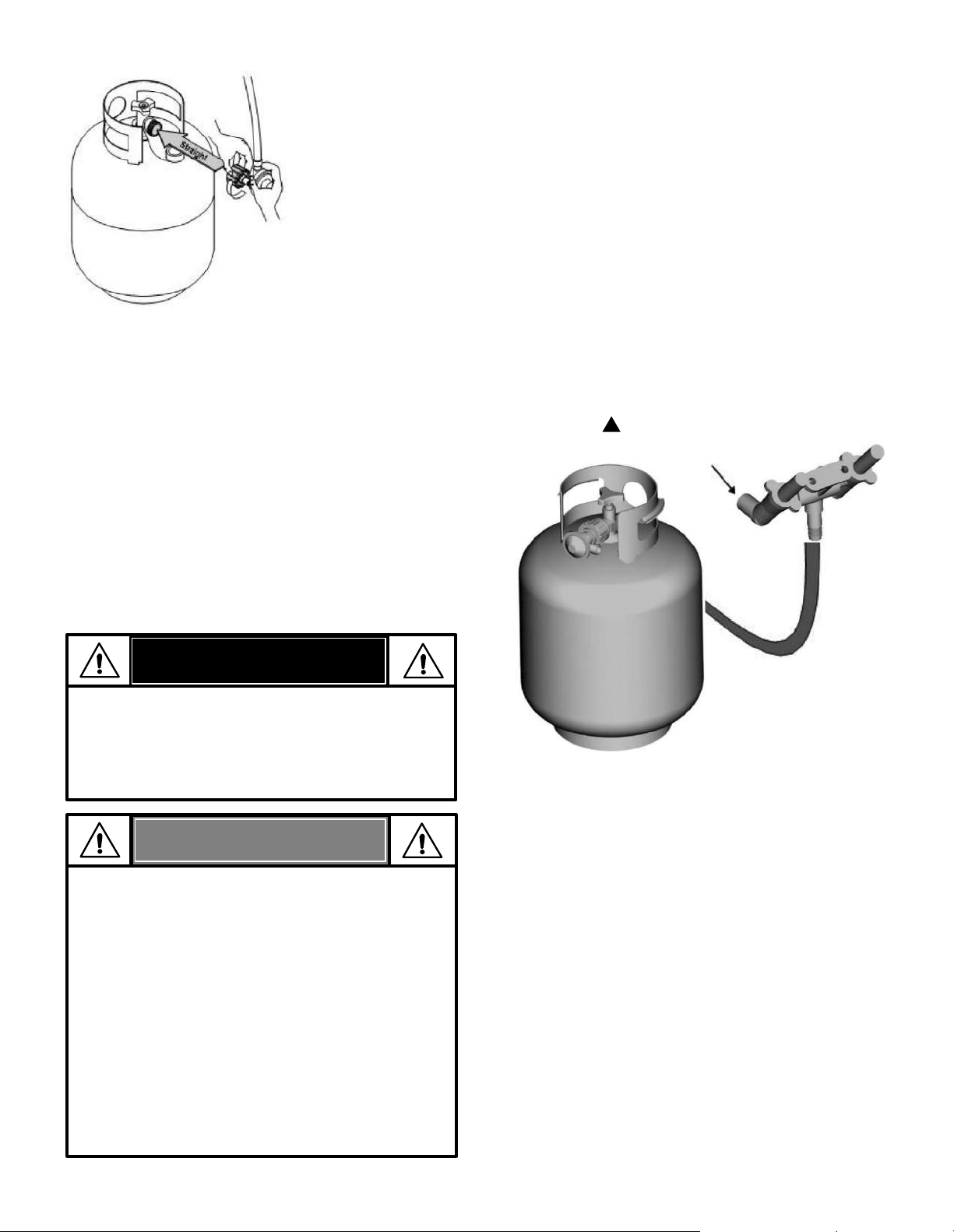
37
Prueba para detectar fugas de las válvulas, las
mangueras y el regulador
1. Gire todas las perillas de control de la parrilla a la
posición deAPAGADO.
2. Cerciórese de que el regulador esté bien conectado al
tanque de gas.
3. Abra por completo la válvula del tanque, girando la
manilla en sentido contrario a las agujas del reloj. Si
escucha un sonido de ráfaga, cierre de inmediato el paso
de gas. La conexió n tiene una fuga considerable.
Corrija
esta situación antes de continuar. Llame para piezas de
repuesto al 1-888-287-0735.
4. Cepille la solución jabonosa en las áreas donde hay
burbujas.
Nunca retire el orificio roscado
del extremo de la válvula
5.
Si aparecen burbujas "crecientes", hay una fuga. Cierre la
válvula del tanque de LP inmediatamente y vuelva a
apretar las conexiones. Si no se pueden detener las fugas,
no intente repararlas. Llame para piezas de repuesto al
1-888-287-0735.
6. Después de hacer una prueba para detectar fugas, cierre
siempre la válvula del tanque de gas, girando la manilla
en el sentido de las agujas del reloj.
•
Si no puede completar la conexión, desconecte el
regulador y repita los pasos 5 y 6. Si a pesar de haberlo
hecho, todavía no puede completar la conexión
, ¡no use
este regulador.
• Llame para piezas de repuesto al 1-888-287-0735.
NOTA:
ADVERTENCIA
• El aparato a gas para uso al aire libre no ha sido
diseñado para ser instalado en embarcaciones.
• El aparato a gas para uso al aire libre no ha sido
diseñado para ser instalado en vehículos de recreo.
• Nunca trate de conectar esta parrilla al sistema de
gas propano independiente de un remolque de
recreo o de una casa rodante.
• No use la parrilla hasta que se realice una prueba de
fugas.
• En caso de detectar una fuga en cualquier momento,
DETÉNGASE y llame a los bomberos.
• Si no puede detener una fuga de gas, ¡cierre de
inmediato la válvula del tanque de gas y llame al
distribuidor o a los bomberos!
Sostenga la tuerca de unión
y el regulador, como se
ilustra, para conectarlos bien
a la válvula del tanque.
6. Gire la tuerca de acoplamiento en el sentido de las
agujas del reloj hasta que esté completamente
apretada. El regulador formará un sello en el
dispositivo de seguridad de la válvula del tanque, lo
que creará cierta resistencia. Se deberá hacer girar la
tuerca entre un cuarto y tres cuartos de vuelta
adicionales, para completar la conexión. Apriétela a
mano únicamente – no use herramientas.
PELIGRO
• No inserte herramientas ni objetos extraños en la
salida de la válvula o en la válvula de alivio de
seguridad. Puede dañar la válvula y causar una fuga.
La fuga de propano puede provocar una explosión,
un incendio, lesiones personales graves o la muerte.
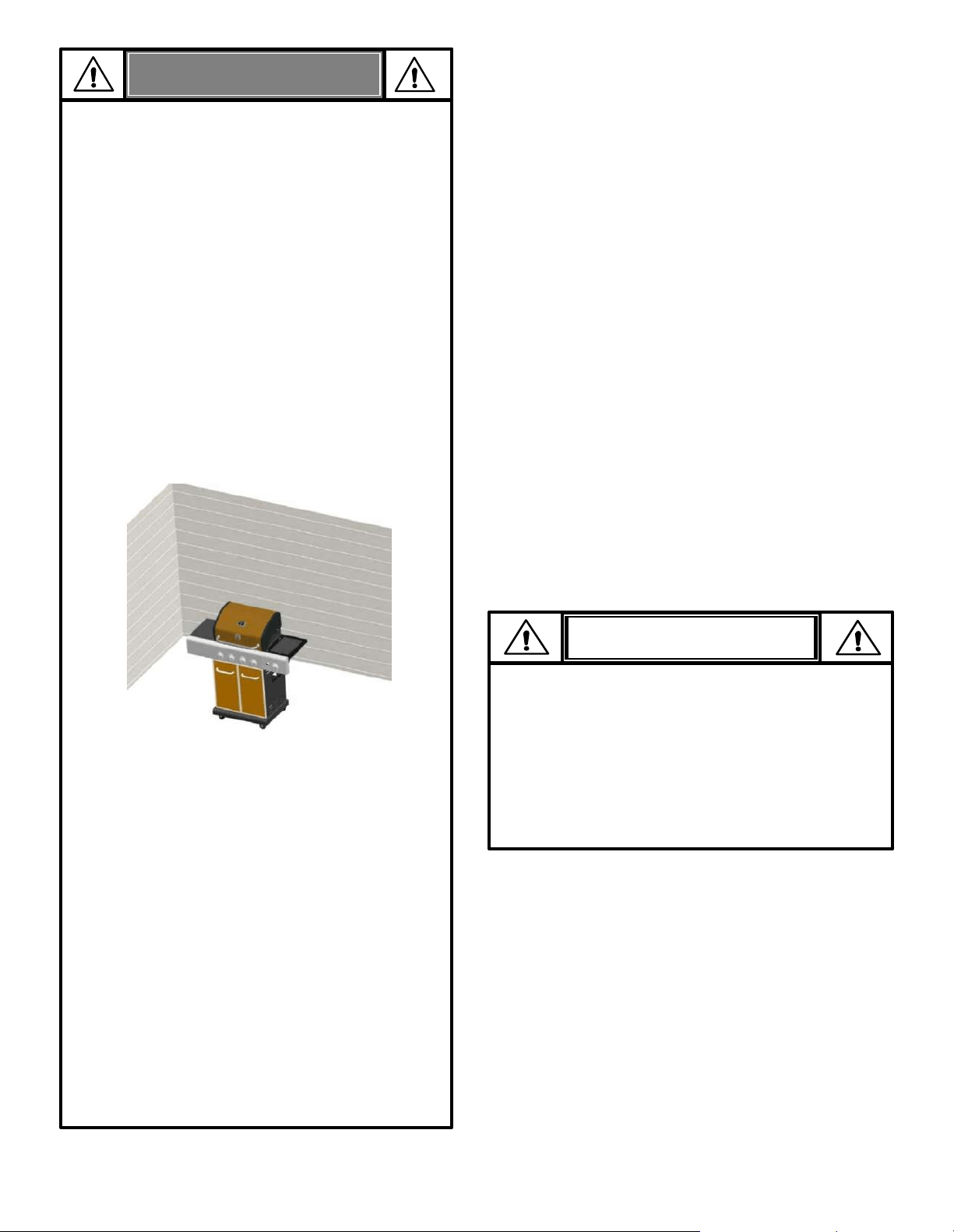
38
Consejos de seguridad
Antes de abrir la válvula del tanque de LP, verifique que la tuerca
de acoplamiento esté apretada.
Cuando la parrilla no esté en uso, apague todas las perillas de
control y la válvula del cilindro LP.
Nunca mueva la parrilla mientras está en funcionamiento o aún
caliente.
Use utensilios de barbacoa de mango largo y manoplas para
evitar quemaduras y salpicaduras.
La carga máxima para el quemador lateral y el estante lateral es
de 10 libras.
La bandeja de goteo debe insertarse en la parrilla y vaciarse
después de cada uso. No retire la bandeja de goteo hasta que la
parrilla se haya enfriado por completo.
Limpie la parrilla CON FRECUENCIA, preferiblemente después de
cada comida al aire libre. Si se usa un cepillo de cerdas para
limpiar cualquiera de las superficies de cocción de la parrilla,
asegúrese de que no queden cerdas sueltas en las superficies de
cocción antes de asar. No se recomienda limpiar las superficies
de cocción mientras la parrilla está caliente.
Si nota que gotea grasa u otro material de la parrilla; determine la
causa, corríjala, luego limpie e inspeccione la válvula. Mantenga
las aberturas de ventilación y el recinto del tanque (carrito de la
parrilla) libres y libres de desechos.
No guarde objetos o materiales dentro del gabinete del carrito
de la parrilla que bloquearían el flujo de aire de combustión hacia
la parte inferior del panel de control o del tazón de la cámara de
combustión.
El regulador puede emitir zumbidos o silbidos durante la
operación. Esto no afectará la seguridad o el uso de la parrilla.
Si tiene un problema con la parrilla, consulte la "Sección de
solución de problemas“.
Si el regulador se congela, apague la parrilla y la válvula del
cilindro LP inmediatamente. Esto indica un problema con el cilindro
y no debe usarse en ningún producto. ¡Regresar al proveedor!
1. Abra la tapa durante la iluminación.
2. Abra la válvula de gas en el tanque.
3. Para encender, gire la perilla del quemador de encendido a HI.
4. Presione y mantenga presionado el botón de encendido electrónico.
5. Si no se enciende en 5 segundos, apague los controles de los
quemadores, espere 5 minutos y repita el procedimiento de encendido.
6. Para encender otros quemadores principales después de encender el
quemador de encendido, gire una perilla de control que se encuentra
junto a un quemador encendido a HI. Encienda el último quemador del
extremo izquierdo.
7. Una vez que los quemadores estén encendidos, ajuste las perillas al
ajuste de llama deseado. Para apagar un quemador individual, gire su
perilla a la posición de APAGADO.
8. Para encender el quemador abrasador, siga los pasos 3 a 5 usando la
perilla del quemador abrasador.
Si el encendedor no funciona, siga las instrucciones de encendido con
fósforos en la página 39.
ADVERTENCIA
• No permita que los niños operen o jueguen cerca de
la parrilla.
• Mantenga el área de la parrilla despejada y libre de
materiales que se quemen.
• No bloquee los orificios en el interior y la parte
posterior de la parrilla.
• Use la parrilla solo en espacios bien ventilados.
NUNCA use la parrilla en un espacio cerrado como
una cochera, garaje, porche, patio cubierto o debajo
de una estructura elevada de cualquier tipo.
• No use carbón o briquetas de cerámica en una
parrilla a gas.
• Use la parrilla por lo menos a 3 pies de cualquier
pared o superficie. Mantenga un espacio de 10 pies
para objetos que puedan incendiarse, o para fuentes
de ignición, etc.
Para usar su parrilla en forma segura y para
evitar lesiones graves:
Pídale al administrador que le indique los requisitos y
los códigos contra incendios que corresponden al
uso de parrillas de gas propano en un edificio de
apartamentos. Si se le permite usarla, hágalo al aire
libre, en la planta baja, dejando un espacio libre de
tres (3) pies entre la parrilla y las paredes o las
barandillas. No la use en balcones o debajo de los
mismos.
• Para personas que viven en apartamentos:
• NUNCA intente encender el quemador con la tapa
cerrada. Una acumulación de gas no encendido
dentro de una parrilla cerrada es peligrosa.
• Nunca opere la parrilla con un tanque de LP fuera
de la posición especificada en las instrucciones de
montaje.
• Siempre cierre la válvula del tanque de LP y retire la
tuerca de acoplamiento antes de mover el tanque
de LP de la posición de operación especificada.
▲
▲
▲
▲
▲
▲
▲
▲
▲
▲
▲
▲
Instrucciones de encendido electrónico de encendido
▲
No se incline sobre la parrilla mientras la enciende.
•
No es posible apagar los fuegos provocados por la grasa
cerrando la tapa. Por razones de seguridad, las parrillas tienen
aberturas de ventilación.
• No use agua para apagar los fuegos provocados por la grasa.
Esto puede ocasionar lesiones. Si surge un fuego provocado
por la grasa, cierre las perillas y el tanque de gas.
• No deje desatendida la parrilla cuando la esté precalentando
o usando la alta temperatura para quemar los residuos de
comida. Si no se ha limpiado. periódicamente la parrilla, se
puede presentar un fuego provocado por la grasa, que puede
dañar al producto.
PRECAUCIÓN
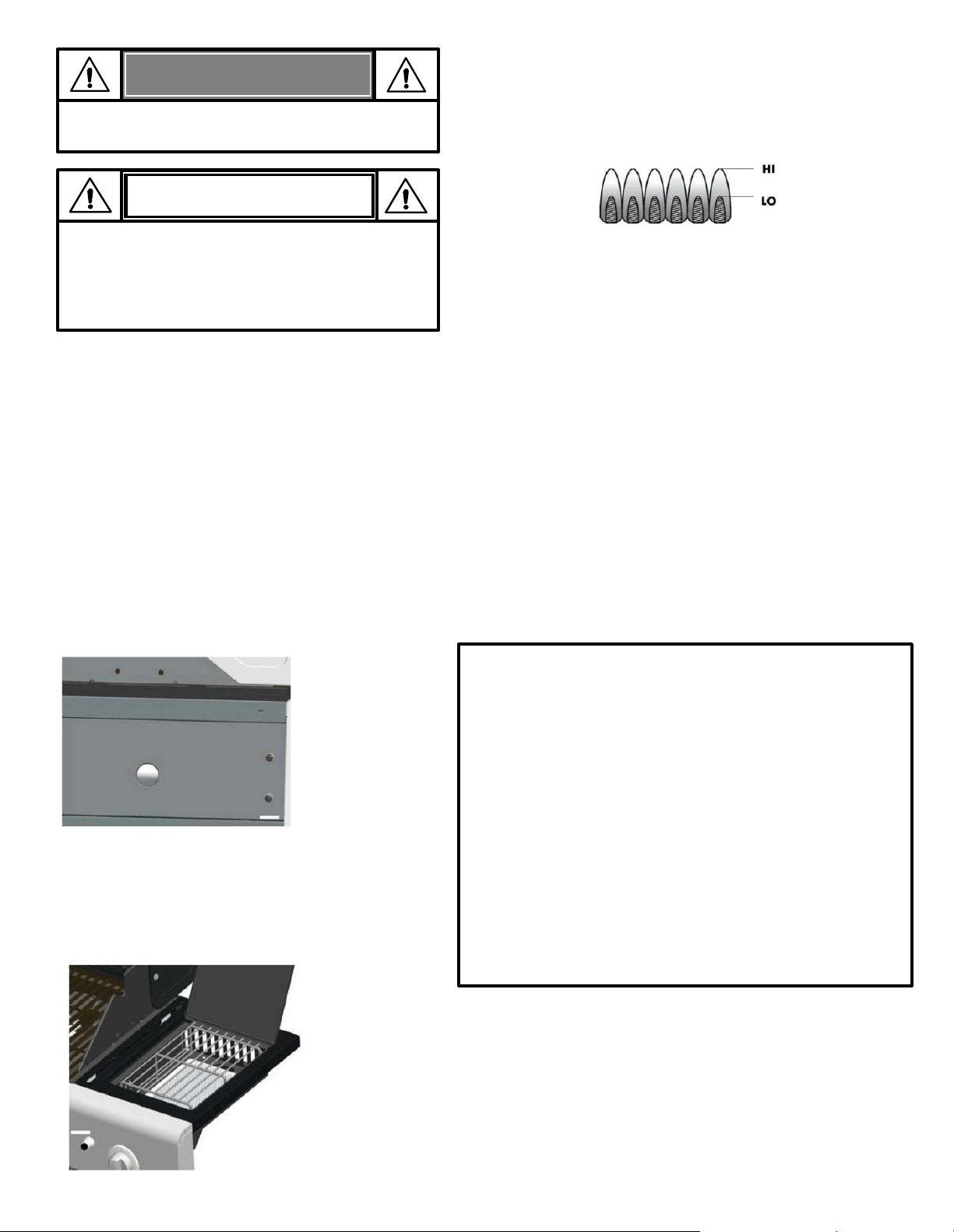
39
ADVERTENCI
A
Gire los controles y la fuente de gas o el tanque
a la posición OFF cuando no esté en uso.
▲
No se incline sobre la parrilla mientras se enciende.
Si la ignición NO ocurre en 5 segundos, apague los
controles del quemador, espere 5 minutos y repita el
procedimiento de encendido. Si el quemador no se
enciende con la válvula abierta, el gas continuará
saliendo del quemador y podría encenderse
accidentalmente con riesgo de lesiones.
PRECAUCIÓN
Instrucción de iluminación de coincidencia
1. Abra la tapa durante la iluminación.
2. Coloque la cerilla en el soporte para cerillas (que cuelga
a la izquierda del panel lateral).
3. Encienda el fósforo e inserte el soporte del fósforo a
través del orificio de encendido en el lado izquierdo de
la cámara de combustión. Alinee el fósforo encendido
con el primer quemador de la izquierda.
4. Gire la perilla del primer quemador izquierdo a la
posición HI. Asegúrese de que el quemador se encienda
y permanezca encendido. Retire el soporte del fósforo de
la caja de fuego y apague el fósforo.
5. Para encender los otros quemadores, gire cada perilla en
sucesión hasta HI.
6. Una vez que los quemadores estén encendidos, ajuste las
perillas al ajuste de llama deseado. Para apagar
cualquier quemador individual, gire su perilla a la
posición de APAGADO.
Encendido de cerillas con quemador abrasador
1. Abra la tapa del quemador abrasador. Encienda el
tanque de LP.
2. Coloque el fósforo encendido cerca del quemador.
3. Gire la perilla del quemador abrasador a HI. Asegúrese
de que el quemador se encienda y permanezca
encendido.
Limpieza General
• No confunda la acumulación marrón o negra de grasa y humo con pintura.
Los interiores de las parrillas a gas no vienen pintados de fábrica (y nunca
deben pintarse). Aplique una solución fuerte de detergente y agua o use un
limpiador de parrillas con un cepillo para fregar para limpiar el interior de la
parrilla. Enjuague y permita que la parrilla se seque por completo.
No
aplique un limpiador cáustico de parrilla/horno a las superficies pintadas.
• Superficies de porcelana: debido a la composición similar al vidrio, la
mayoría de los residuos se pueden limpiar con una solución de agua y
bicarbonato de sodio o un limpiador especialmente formulado. Use un polvo
para fregar no abrasivo para las manchas difíciles.
Condimento de rejilla de hierro fundido (si corresponde)
Primer uso – antes de su primer uso, sazone sus rejillas de hierro fundido de
la siguiente manera: enjuague las rejillas de hierro fundido con agua
caliente. No use jabón. Seque bien las rejillas con una toalla de tela. Cubra
las rejillas con aceite vegetal o cualquier spray antiadherente para cocinar.
Coloque las rejillas en la parrilla. Encienda la parrilla y aumente lentamente
la temperatura a 350° - 400° F. Caliente las rejillas durante una hora.
Apague la parrilla y deje que las parrillas se enfríen por completo antes de
usarlas para cocinar.
Limpieza – no use jabón para limpiar las rejillas. Limpie las rejillas con un
cepillo duro y agua caliente. Seque bien las rejillas con una toalla de tela.
Re-sazonado – Vuelva a curar las rejillas cuando aparezcan manchas de
óxido en la superficie de la rejilla. Al volver a sazonar las parrillas, se puede
usar jabón con agua caliente para limpiar las parrillas. Después de limpiar,
seque bien las rejillas con una toalla de tela. Cubra las rejillas con aceite
vegetal o cualquier spray antiadherente para cocinar. Coloque las rejillas
en la parrilla. Encienda la parrilla y aumente lentamente la temperatura a
350° - 400° F. Caliente las rejillas durante una hora. Apague la parrilla y
deje que las rejillas se enfríen por completo antes de volver a usarla.
Comprobación de la llama del quemador
• Retire las rejillas de cocción y los difusores de calor. Encienda los
quemadores y gire las perillas de ALTO a BAJO. Debería ver una llama
más pequeña en el ajuste BAJO y una llama más alta en el ajuste ALTO.
Compruebe siempre la llama antes de cada uso. Si solo se ve una llama
baja, consulte "Caída repentina o llama baja" en la sección de solución de
problemas en la página 60.
Apagar la parrilla
• Gire todas las perillas a la posición de APAGADO. Apague el tanque de
LP. Cuando termine de asar, levante la tapa de la parrilla para permitir
que la parrilla se enfríe por completo. Si la tapa de la parrilla está
cerrada mientras la parrilla se está enfriando, se puede producir
condensación en las superficies interiores de la parrilla, lo que puede
causar que las partes internas se oxiden.
Comprobación del encendedor
• Apague el tanque de LP. Mantenga presionado el botón de encendido
electrónico. Debe escucharse un "clic" y deben verse chispas cada vez
entre la caja colectora o el quemador y el electrodo. Consulte la sección
de solución de problemas en las páginas 59 a 61 si no hay clics ni chispas.
Chequeo de las valvulas
• Importante: asegúrese de que el gas en el tanque de LP esté cerrado
antes de verificar que la válvula y las perillas estén en la posición de
apagado. Para revisar las válvulas, primero presione las perillas y
suéltelas. Las perillas deben saltar hacia atrás. Si las perillas no
retroceden, reemplace el conjunto de la válvula antes de usar la parrilla.
Gire las perillas a la posición BAJA y luego vuelva a colocarlas en la
posición APAGADO. Las válvulas deben girar suavemente.
Comprobación de manguera
• Antes de cada uso, verifique si la manguera está cortada o desgastada.
Reemplace la manguera dañada antes de usar la parrilla. Utilice
únicamente la válvula/manguera/regulador como se especifica en la lista
de piezas de esta Guía de uso y cuidado.
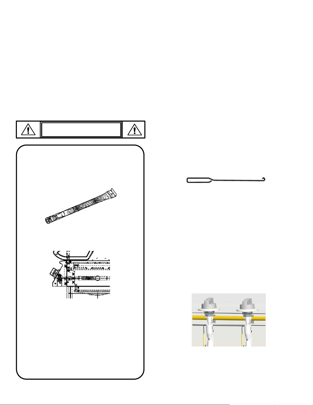
40
Almacenamiento de su parrilla
• Limpie las parrillas de cocción.
• Almacene en un lugar seco.
• Cuando el tanque de LP esté conectado a la parrilla, guárdelo al
aire libre en un espacio bien ventilado y fuera del alcance de los
niños.
• Cubra la parrilla si se almacena al aire libre. Elija entre una
variedad de cubiertas para parrillas que ofrece el fabricante.
Disponible en Kenmoregrill.com.
• Guarde la parrilla en el interior SOLAMENTE si el tanque de LP está
apagado y desconectado. Retire el tanque de LP de la parrilla y
guárdelo al aire libre.
• Cuando retire la parrilla del almacenamiento, siga las instrucciones
de "Limpieza del conjunto del quemador" antes de encender la
parrilla.
IMPORTANTE: Siempre asegúrese de que los tubos del
quemador venturi estén limpios. Un tubo quemador
venturi tiene un área estrecha en la que las arañas
tienden a construir nidos.
PRECAUCIÓN
¡ALERTA DE ARAÑA!
• Superficies pintadas: Lave con un detergente suave o un
limpiador no abrasivo y agua jabonosa tibia. Seque con un
paño suave no abrasivo.
• Superficies de acero inoxidable: Para mantener la apariencia
de alta calidad de su parrilla, lávela con un detergente suave
y agua jabonosa tibia. Luego seque con un paño suave. Los
depósitos de grasa horneados pueden requerir el uso de una
almohadilla de limpieza plástica abrasiva. Use solo en la
dirección del acabado cepillado para evitar daños. No use la
almohadilla abrasiva en áreas con gráficos.
• Superficies de cocción: Si se usa un cepillo de cerdas para
limpiar cualquiera de las superficies de cocción de la parrilla,
asegúrese de que no queden cerdas sueltas en las superficies
de cocción antes de asar. No se recomienda limpiar las
superficies de cocción mientras la parrilla está caliente.
• Bandeja de goteo y taza: cuando la parrilla se haya enfriado
por completo después de su uso, retire la bandeja de goteo y
la taza de goteo para limpiarlas.
v
Si nota que su parrilla se vuelve difícil de encender o que
la llama no es tan fuerte como debería ser, tómese el
tiempo para revisar y limpiar los venturi.
Las arañas y los insectos pequeños han producido
“fogonazos”. Las arañas tejen sus telas, hacen sus nidos y
ponen sus huevos en los tubos Venturi de las parrillas, que
obstruyen el paso del gas al quemador. El gas que se
acumula dentro de los tubos Venturi, ubicados en la parte
posterior del tablero de control, se puede encender. A esto
se le llama "fogonazo", y puede dañar su parrilla e, incluso,
puede producir lesiones.
Para evitar los fogonazos y garantizar el buen
funcionamiento, retire la unidad del quemador y del tubo
Venturi y límpielos antes de usar la parrilla, si no la ha usado
durante un tiempo prolongado.
Limpieza del conjunto del quemador
Siga estas instrucciones para limpiar y/o reemplazar piezas del
conjunto del quemador o si tiene problemas para encender la parrilla.
1. Apague el gas girando las perillas de control a la posición de
apagado y cierre la válvula del tanque de LP.
2. Retire las rejillas de cocción y los difusores de calor.
3. Retire el pasador de aletas adjunto de la parte trasera de cada
quemador. Consulte la figura A en la página 41.
4. Levante con cuidado cada quemador y sepárelos de las
aberturas de las válvulas. Sugerimos tres formas de limpiar los
tubos de los quemadores. Usa el más fácil para ti.
5. Use un cepillo de alambre para fregar toda la superficie exterior
del quemador para eliminar los residuos de alimentos y la
suciedad.
6. Limpie los puertos bloqueados con un alambre rígido, como un
sujetapapeles abierto.
7. Revise el quemador para ver si está dañado. Debido al desgaste
y la corrosión normales, algunos orificios pueden agrandarse. Si
se encuentran grietas o agujeros grandes en el quemador,
reemplácelos.
8. Vuelva a colocar con cuidado los quemadores. Ver Fig. A y B en
la página 41.
9. Fije la parte trasera de cada quemador al soporte y vuelva a
conectar la chaveta. Consulte la Fig. A en la página 41.
10. Vuelva a colocar los difusores de calor y las parrillas de cocción.
MUY IMPORTANTE: Los tubos de los quemadores deben
volver a acoplarse en las aberturas de las válvulas.
Vea las ilustraciones a continuación.
(A) Doble un alambre rígido (una percha liviana funciona bien)
en un gancho pequeño. Pase el gancho a través de cada
tubo de quemador varias veces.
(B) Use un cepillo angosto para botellas con mango flexible
(no use un cepillo de alambre de latón) y pase el cepillo a
través de cada tubo del quemador varias veces.
(C) Use protección para los ojos: Use una manguera de aire
para forzar el aire dentro del tubo del quemador y fuera de
los puertos del quemador. Verifique cada puerto para
asegurarse de que salga aire por cada orificio.
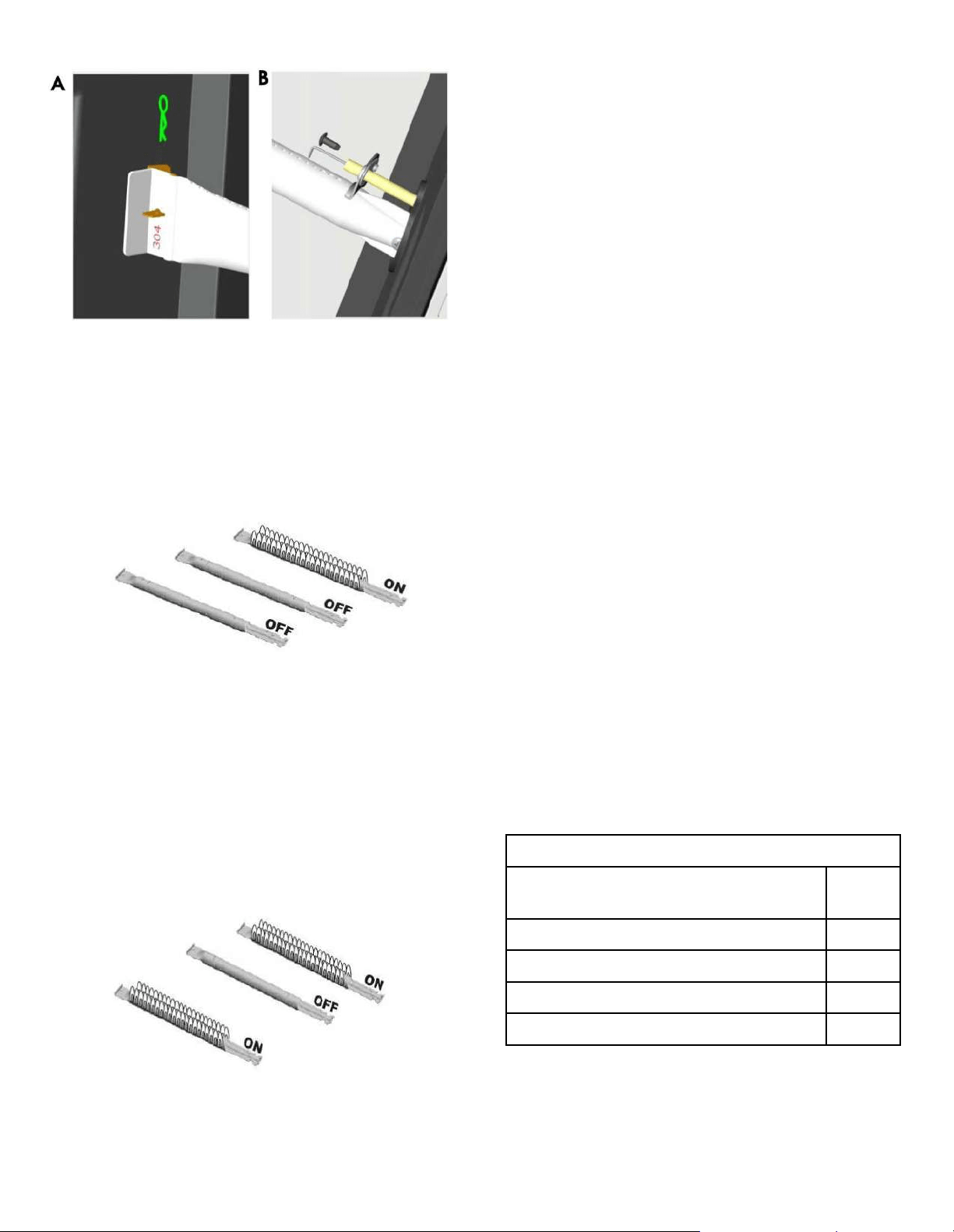
41
Seguridad alimentaria
La seguridad alimentaria es una parte muy importante para disfrutar
de la experiencia de cocinar al aire libre. Para mantener los
alimentos a salvo de bacterias dañinas, siga estos cuatro pasos
básicos:
•
Limpiar: Lávese las manos, los utensilios y las superficies con
agua jabonosa caliente antes y después de manipular carnes y
aves crudas.
• Separe: separe las carnes y aves crudas de los alimentos listos
para comer para evitar la contaminación cruzada. Use un plato
y utensilios limpios cuando retire los alimentos cocidos.
• Cocine: cocine bien la carne y las aves para matar las
bacterias. Use un termómetro para garantizar la temperatura
interna adecuada de los alimentos.
• Refrigere: Refrigere los alimentos preparados y las sobras de
inmediato.
Para más información llame al: Carnes y Aves Hotline al 1-800-535-
4555 (en Washington, DC (202) 720 a 3333, de 10:00 am 4:00 pm
EST).
Cómo saber si las carnes están bien
• La carne y aves de corral cocinado en una parrilla a menudo se
dora rápidamente en el exterior. Use un termómetro para carne
para verificar que haya alcanzado una temperatura interna
segura, y corte la carne para verificar si hay signos visuales de
cocción.
• Aves enteras debe alcanzar 180 ° F; pechos, 170 ° F. El jugo
debe salgan claros y la carne no deben ser de color rosa.
• Las hamburguesas hechas con carne molida o ave, debe
alcanzar 160 ° F, y ser de color marrón en el medio, sin jugos de
color rosa. Carne de res, ternera y cordero, asados y chuletas
se pueden asar a 145 ° F. Todos los cortes de cerdo debe
alcanzar 160 ° F.
• NUNCA parcialmente carne o de aves y terminar la cocción
más tarde. Cocine los alimentos completamente, para destruir
las bacterias dañinas.
• Cuando recaliente los alimentos de comida rápida o las carnes
ya cocidas por completo perros calientes, parrilla a 165 ° F, o
hasta que emitan vapor.
ADVERTENCIA: Para asegurarse de que es seguro para comer,
los alimentos deben cocinarse a las temperaturas internas
mínimas que figuran en la siguiente tabla
.
Cocina indirecta
Las aves de corral y los grandes cortes de carne se cocinan
lentamente a la perfección en la parrilla por calor indirecto.
Coloque los alimentos sobre los quemadores sin encender;
el calor de los quemadores iluminados circula suavemente
por toda la parrilla, cocinando carne o aves sin tocar una
llama directa. Este método reduce en gran medida los
brotes cuando se cocinan cortes grasos extra porque no
hay llama directa para encender las grasas y los jugos que
gotean durante la cocción.
Instrucciones para cocinar indirectos
• Siempre cocine con la tapa cerrada.
• Una vez que los quemadores estén encendidos, apague
cualquier quemador individual girando su perilla a la
posición APAGADO.
• Debido a las condiciones climáticas, los tiempos de
cocción pueden variar. En condiciones de frío y viento, es
posible que se deba aumentar la temperatura para
asegurar suficiente calor de cocción.
• Coloque los alimentos sobre los quemadores sin
encender.
1 Quemador de cocina
Consume menos combustible.
2 Quemador de cocina
Gran cocción indirecta a fuego lento. Produce
un calentamiento lento y uniforme. Ideal para
asados y horneados lentos.
* Departamento de Agricultura de Estados Unidos
** Permitir que la carne de un descanso de tres minutos
antes de cortarlo o consumir.
USDA *Temperaturas internas mínimas de cocción
Carne de res, ternera, cordero y cerdo
– Cortes enteros**
145°F
Pescado 145°F
Carne de res, ternera, cordero y cerdo – Carne 160°F
Platos a base de huevos 160°F
Pavo, pollo y pato - piezas enteras, y molida 165°F
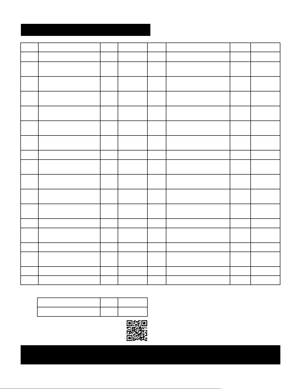
42
LISTAR DE PIEZASTES (1/2)
Clave Descripción Cant. Pieza No. Clave Descripción Cant. Pieza No.
1
Tapa del quemador lateral
1 40200500 18 Regulador 1 40800115
2
Rotación de la varilla, tapa del
quemador lateral
1 40900221 19-A
Bisel de la perilla de control
(negro mate)
5 40920036
3 Rejilla del quemador lateral 1 40900222 19-B
Bisel de la perilla de control
(cromo negro)
5 40900502
4 Quemador abrasador 1 40900142 20-A
Perilla de control, quemador
principal (cobre cromado)
4 40920206
5 Alambre de enncendido doble 1 40900220 20-B
Perilla de control, quemador
principal (cromo negro)
4 40900517
6 Base del quemador lateral 1 40900114 21-A
Perilla de control, quemador
abrasador (cobre cromado)
1 40920224
7
Caja de goteo, quemador
lateral
1 40900116 21-B
Perilla de control, quemador
abrasador (cromo negro)
1 40900505
8 Panel lateral derecha 1 40900506 22 Repisa Inferior 1
40900516
9
Fascia, estante del lado
derecho
1 40920046 23 Rueda Estándar 1 40900214
10
Barra de ángulo de apoyo de la
plataforma lateral
2 40900109 24 Rueda giratoria 1 40900213
11-A
Módulo de IG electrónica
(negro)
1 40820122 25 Rueda giratoria con freno 2 40900212
11-B
Módulo de IG electrónica
(cromo negro)
1 40800123 26 Caja magnética de la puerta 1 40200072
12 Panel de control 1 40900507 27 Imán de la puerta 4 40200094
13
Válvula de gas, quemador
principal
4 40900205 28
Buje de agujero 1 40400005
14 Manguera de quemador lateral 1 40900216 29 Panel lateral derecho 1 40900508
15
Válvula de gas, quemador
abrasivo
1 40900219 30 Deflector del tanque 1 40200070
16 Manifold, quemador lateral 1 40200045 31 Titular del tanque 1 40800130
17 Manifold, quemador principal 1 40800037 32 Puerta derecha (Negro) 1 40920132
No aparece en la foto
Paquete de Hardware 1 40900350
Manual 1 40900499
NOTA: Algunas piezas de la parrilla que se muestran en los pasos de montaje pueden diferir ligeramente en
apariencia de las de su modelo de parrilla en particular. Sin embargo, el método de montaje sigue siendo el mismo.
Si le falta hardware o tiene pa rtes dañadas
después de desempaquetar la parrilla, llame al
1-888-287-0735 para reemplazarlo.
Para solicitar piezas de repuesto después de usar
la parrilla, llame al 1-888-287-0735.
O visítenos en Kenmoregrill.com

43
LISTAR DE PIEZASTES (2/2)
No aparece en la foto
Paquete de Hardware 1 40900350
Manual 1 40900499
NOTA: Algunas piezas de la parrilla que se muestran en los pasos de montaje pueden diferir ligeramente en
apariencia de las de su modelo de parrilla en particular. Sin embargo, el método de montaje sigue siendo el mismo.
Si le falta hardware o tiene pa rtes dañadas
después de desempaquetar la parrilla, llame al
1-888-287-0735 para reemplazarlo.
Para solicitar piezas de repuesto después de usar
la parrilla, llame al 1-888-287-0735.
O visítenos en Kenmoregrill.com
Clave Descripción Cant. Pieza No. Clave Descripción Cant. Pieza No.
33-A
Manija de la puerta (cromo
cromado)
2 40920076 52
Parachoques de goma de
silicona
2 50300205
33-B
Manija de puerta (cromo
negro)
2 40900503 53-A
Medidor de temperatura (cobre
cromado)
1 40920218
34 Puerta izquierda (negro) 1 40920127 53-B
Medidor de temperatura (cromo
negro)
1 40900201
35 Pasador 8 110050 54-A Logotipo (cromo negro) 1 407F10106
36
Barra de ángulo de soporte
del carro
2 40900509 54-B Logotipo (cromo negro) 1 407F10106
37 Panel lateral izquierdo 1 40900510 55 Varilla giratoria, tapa 2 50300207
38 Panel posterior 1 40900511 56 Espaciador de aislamiento, tapa 2 40700022
39 Sujetador del cerillo 1 40800128 57-A
Bisel, asa de la tapa (negro
mate)
2 40900013
40
Soporte del sujetador del
cerillo
1 40800129 57-B
Bisel, manija de la tapa (cromo
negro)
2 40900501
41
Cadena de la barilla de
encendido
1 41100105 58 Tapa (negro) 1 40700500
42 Soporte de puerta 1 40900512 59-A Asa de la tapa (cobre cromado) 1 40920012
43 Soporte de Puerta derecha 1 40200126 59-B Asa de la tapa (cromo negro) 1 40900500
44 Soporte de Puerta izquierda 1 40200125 60 Estante de calentamiento 1 40900203
45 Tren trasero 1 40900513
61 Rejilla de cocimiento 2 40900204
46 Taza de goteo 1 40800026 62 Difusor de calor 4 40800023
47 Clip de la copa de goteo 1 40800131 63 Tubo de Transporte de Llama 3 40800022
48 Bandeja de goteo 1 40900106 64 Caja de fuego 1 40900104
49
Fascia, estante lateral
izquierdo
1 40900514 65 Electrodo, quemador principal 1 40900207
50 Estantería lateral izquierda 1 40900515 66 Quemador principal 4 40900030
51
Parachoques de goma de
silicona
2 40700103 67 Manga de tubo 4 40900225
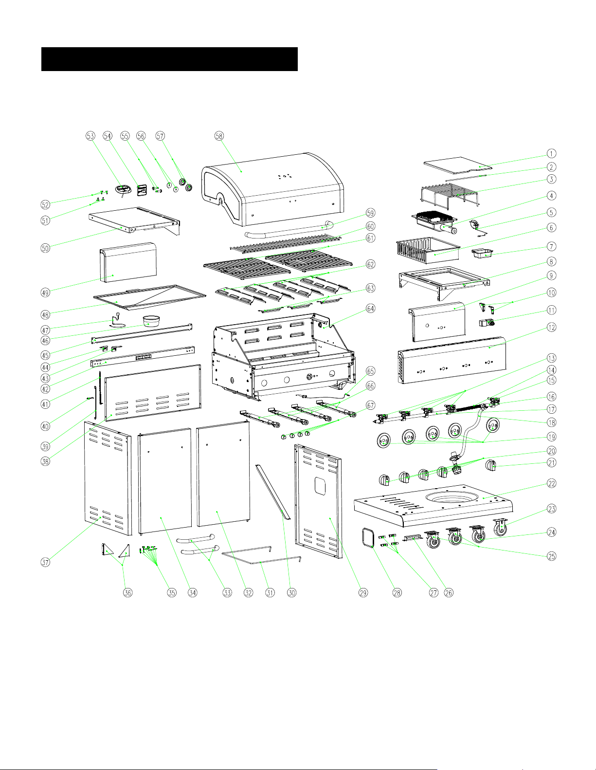
44
DIAGRAMA DE PIEZAS
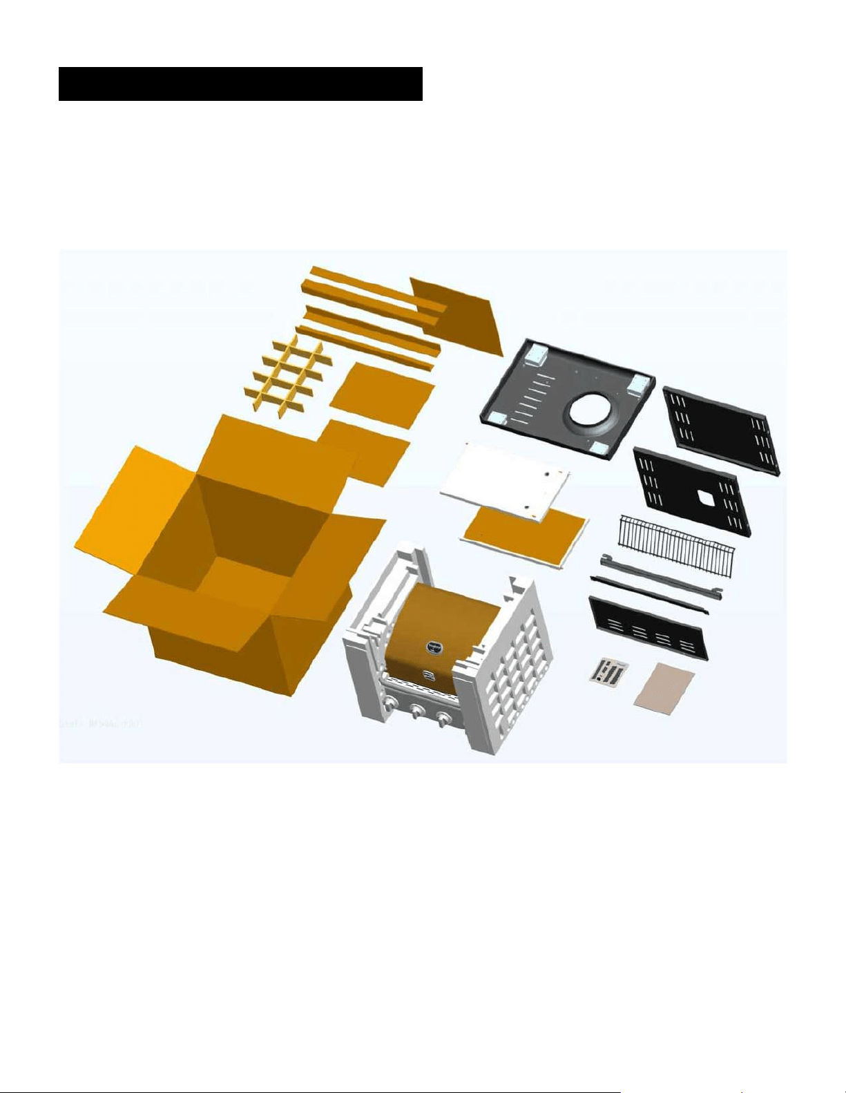
45
ANTES DEL MONTAJE
AVISO: Una vez que haya desempacado la parrilla, verifique todas las piezas de la parrilla con las
imágenes de las páginas 45-47. Si falta alguna pieza o está dañada, llame al 1-888-287-0735.

46
ANTES DEL MONTAJE

47
ANTES DEL MONTAJE

48
LEA Y REALICE CUIDADOSAMENTE TODAS LAS INSTRUCCIONES DE ASAMBLEA EN LAS PÁGINAS
SIGUIENTES.
Las herramientas requiridas:
• Destornillaror (no proporcionado)
• Llave ajustable (no proporcionada)
• El hardware siguiente se proporciona en el paquete de ampolla para el uso conveniente.
ASAMBLEA
Tornillo M4x10
Cantidad: 36 piezas
Batería AA
Cantidad: 1 pieza
Tornillo M5x10
Cantidad: 4 piezas
Arandela plana M5
Cantidad: 4 piezas
Tornillo M6x13
Cantidad: 32 piezas
Arandela de compresión M6
Cantidad: 8 piezas
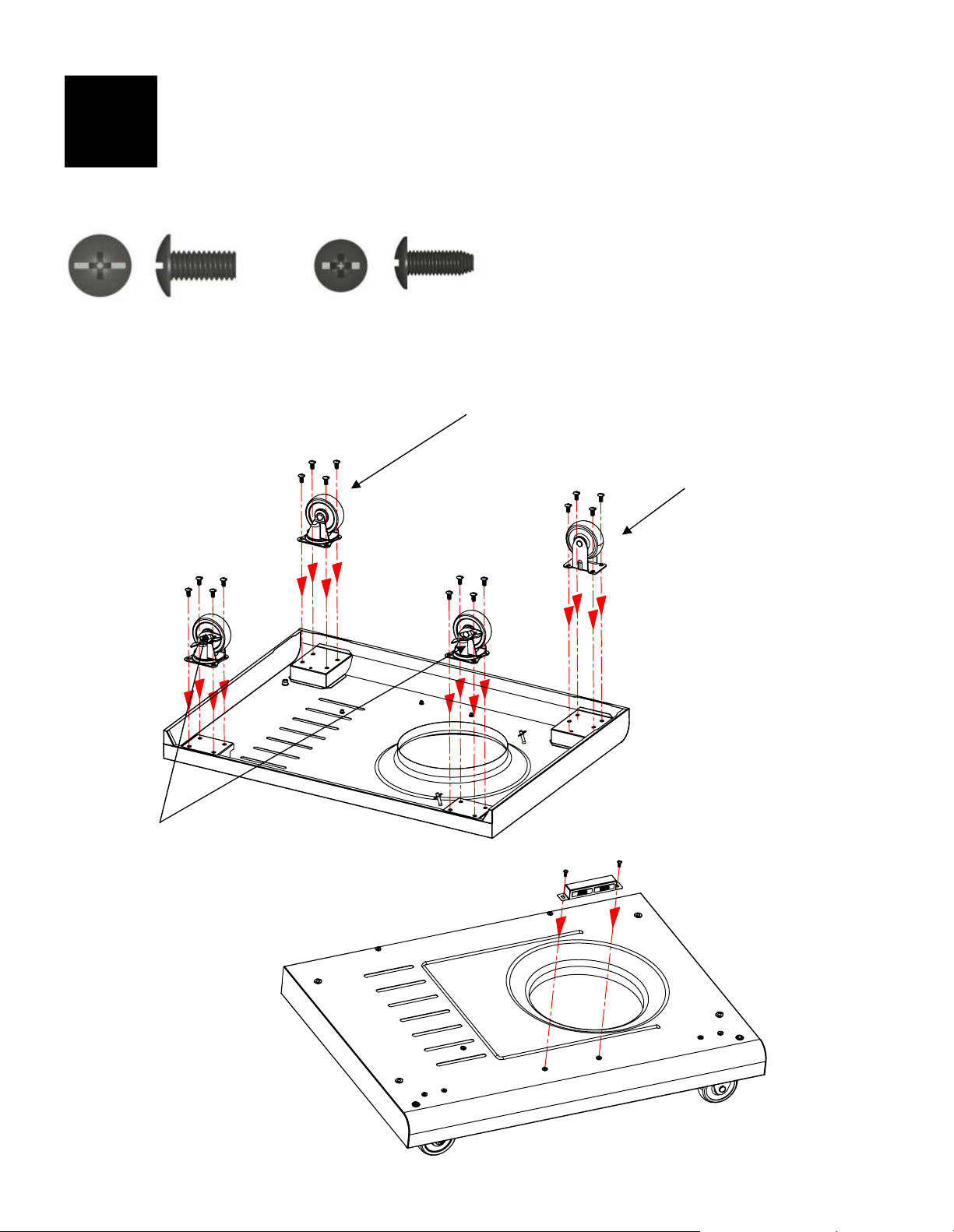
49
Estante inferior
Voltee el estante inferior boca abajo. Fije las ruedas al estante inferior con (16) tornillos M6x13.
Nota: Instale cada rueda en la posición correcta como se muestra en la figura a continuación.
La rueda estándar (no giratoria) solo se instalará en una dirección.
Gire el estante inferior con el lado derecho hacia arriba. Fije los imanes de la puerta al estante
inferior con (2) tornillos M4x10.
Tornillo M6x13
Cantidad: 16 piezas
1
Tornillo M4x10
Cantidad: : 2 piezas
Rueda giratoria
(Nº de pieza: 40900213)
Rueda estándar
(Nº de pieza: 40900214)
Rueda giratoria con freno
(Nº de pieza: 40900212)
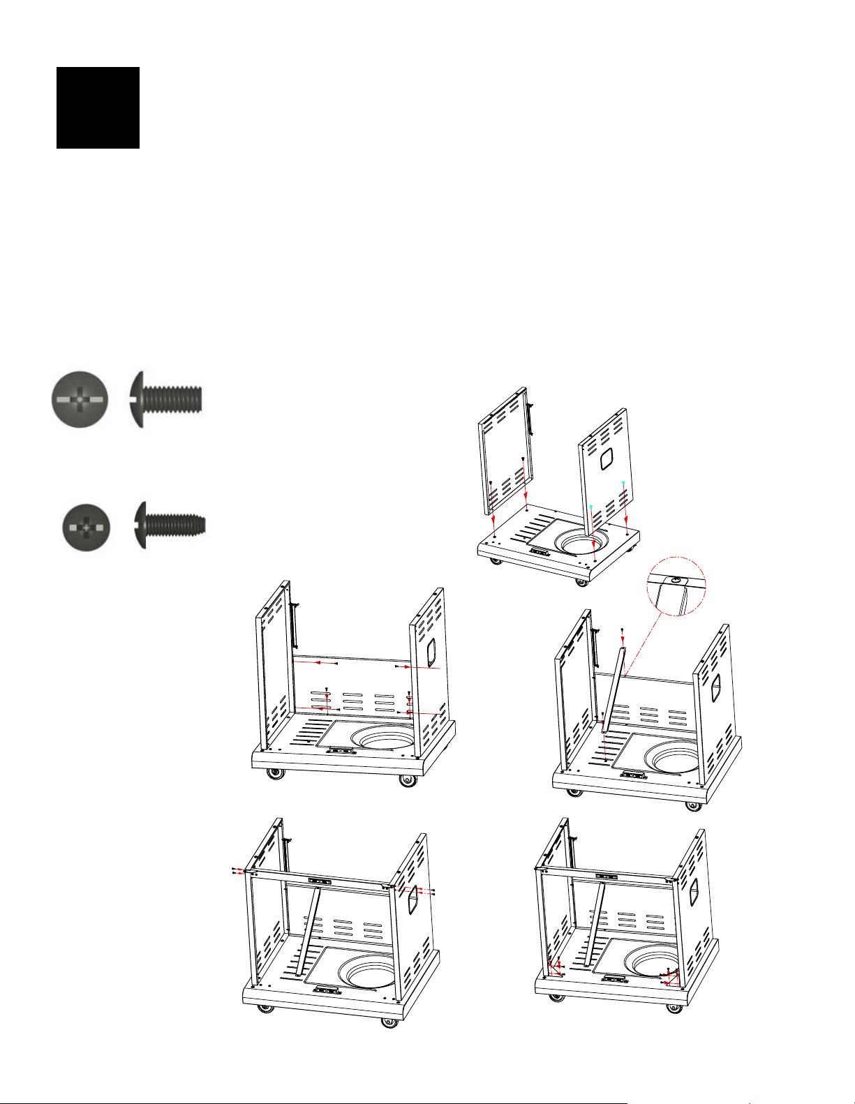
50
Carro
Para colocar los paneles laterales, alinee los orificios del panel lateral con los orificios para insertar
tornillos en cada lado del estante inferior.
Nota: El panel lateral izquierdo tiene un soporte para fósforos.
Fije los paneles laterales izquierdo y derecho a los lados del estante inferior con (4) tornillos M6x13. (A)
Fije el panel posterior al estante inferior y dos paneles laterales con (6) tornillos M4x10. (B)
Fije la barra deflectora del tanque al panel posterior y al estante inferior con (2) tornillos M4x10. (C)
Alinee los orificios del soporte de la puerta con los orificios de los paneles laterales. Fije el soporte de la
puerta a los paneles laterales con (4) tornillos M4x10. (D) Nota: Fije el soporte de modo que los imanes
queden arriba.
La barra del deflector del tanque se encuentra debajo del estante del lado izquierdo
(40900515).
Alinee los orificios de las barras angulares de soporte del carro con los orificios del estante inferior y los
paneles laterales. Fije las barras angulares con (8) tornillos M4x10. (E)
2
Tornillo M6x13
Cantidad: 4 piezas
Tornillo M4x10
Cantidad: 20
piezas
A
B
C
D
E
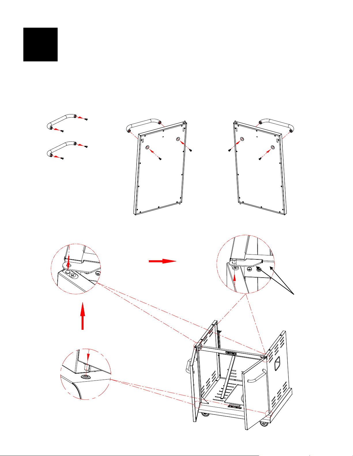
A
B
51
Puerta principal
Retire los (4) tornillos M5x15 preensamblados de los extremos de las manijas de las puertas y
utilícelos para sujetar las manijas a las puertas. (A)
Inserte el pasador en la parte inferior de cada puerta en el orificio del panel inferior. Inserte el
pasador en la parte superior de cada puerta a través del orificio en la bisagra del soporte de la
puerta. (B)
IMPORTANTE: si las puertas no se alinean cuando están cerradas o no se cierran libremente, es
posible que sea necesario ajustar las bisagras. Afloje los tornillos de la bisagra, ajuste la posición de
la bisagra según sea necesario y vuelva a apretar los tornillos.
3
Tornillos de bisagra
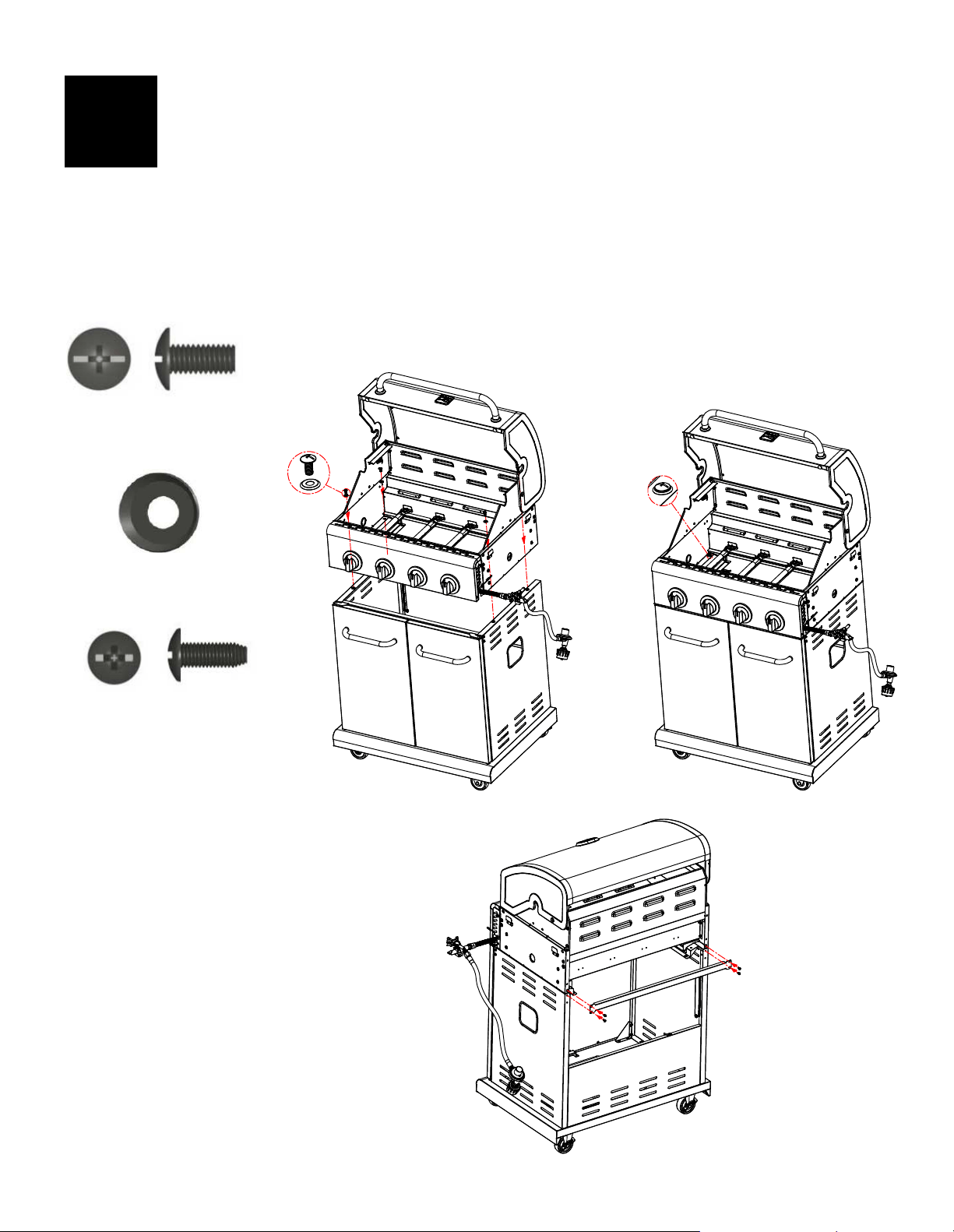
52
Cabezal de parrilla al carrito
IMPORTANTE: Retire las bridas y el material de empaque de la manguera del regulador, la válvula del
quemador abrasador y el cable de ignición. Jale la manguera y el cable de ignición hacia el lado
derecho de la cabeza de la parrilla.
Este paso requiere que dos personas levanten y coloquen el cabezal de la parrilla en el carro.
Baje con cuidado el cabezal de la parrilla sobre el carro. Asegúrese de que la manguera del
regulador y el cable de ignición cuelguen fuera del carro. Abra la tapa y fije la cabeza al carro con
(4) tornillos M6x13 y arandelas de compresión M6. (A y B)
Alinee los orificios del riel posterior con los orificios de los paneles laterales y la cámara de
combustión. Fije el riel trasero con (4) tornillos M4x10. (C)
Tornillo M6x13
Cantidad: 4 piezas
4
Tornillo M4x10
Cantidad: 4 piezas
Arandela de compresión M6
Cantidad: 4 piezas
B
C
A
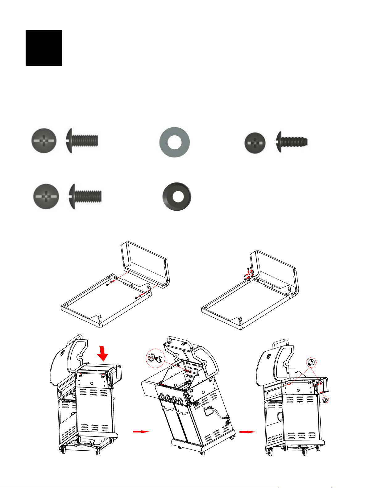
53
Estante del lado izquierdo
Fije la fascia al estante del lado izquierdo con (2) tornillos M5x10 y (2) arandelas planas M5. (A)
Fije la barra angular de soporte del estante al estante lateral y al frente con (4) tornillos M4x10. (B)
Cuelgue el estante del lado izquierdo en los soportes del lado izquierdo de la cámara de combustión. (C)
Fije el estante a la cámara de combustión de la siguiente manera:
Desde el interior hacia el exterior de la cámara de combustión con (2) tornillos M6x13 y
(2) arandelas de compresión M6. (D)
IMPORTANTE: asegúrese de que el panel lateral de la cámara de combustión y el panel de
control estén alineados antes de colocar el estante lateral.
Del exterior al interior del hogar con (2) tornillos M6x13 y (1) tornillo M4x10. (E)
5
B
C
A
D
E
Tornillo M5x10
Cantidad: 2 pcs
Tornillo M4x10
Cantidad: 5 piezas
Arandela de compresión M6
Cantidad: 2 piezas
Arandela plana M5
Cantidad: 2 piezas
Tornillo M6x13
Cantidad: 4 piezas
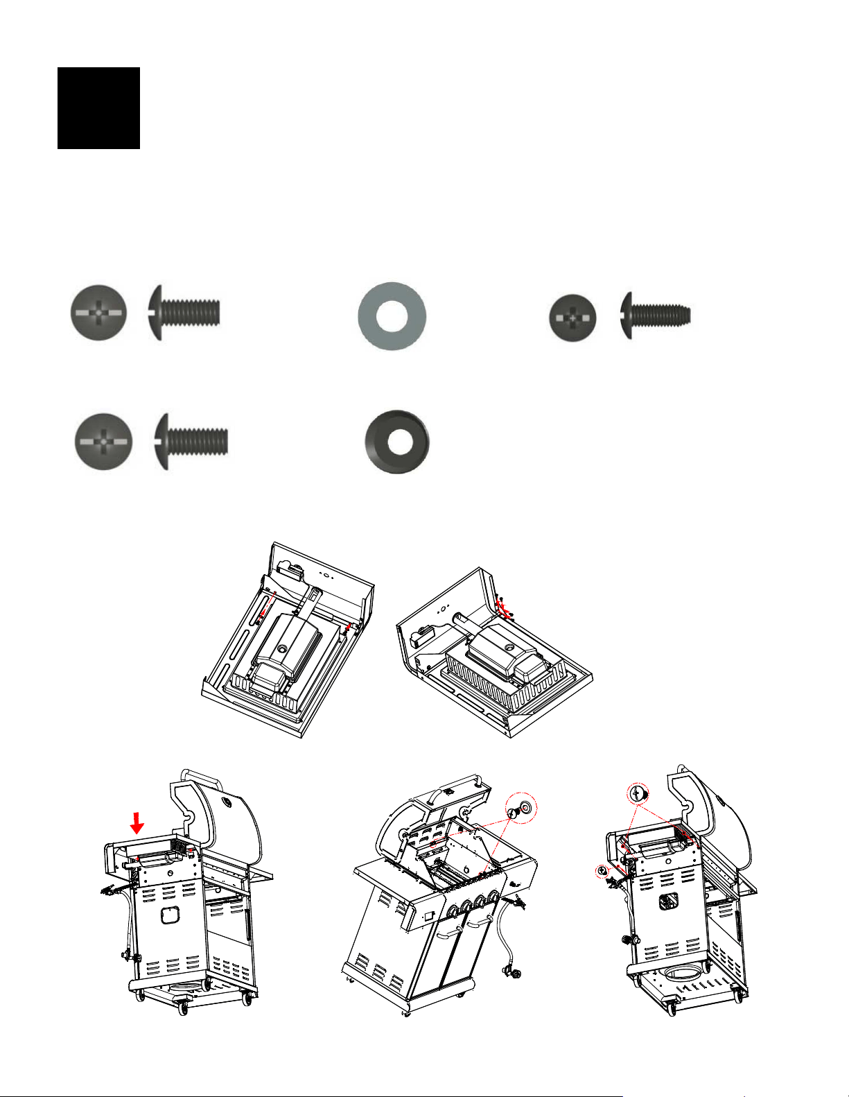
54
Estante lateral derecho
Fije la fascia al estante del lado derecho con (2) tornillos M5x10 y (2) arandelas planas M5. (A)
Fije la barra angular de soporte del estante al estante lateral y al frente con (4) tornillos M4x10. (B)
Cuelgue el estante del lado derecho en los soportes del lado izquierdo de la cámara de combustión. (C)
Fije el estante a la cámara de combustión de la siguiente manera:
Desde el interior hacia el exterior de la cámara de combustión con (2) tornillos M6x13 y
(2) arandelas de compresión M6. (D)
IMPORTANTE: asegúrese de que el panel lateral de la cámara de combustión y el panel de
control estén alineados antes de colocar el estante lateral.
Del exterior al interior del hogar con (2) tornillos M6x13 y (1) tornillo M4x10. (E)
6
B
C
A
D
E
Tornillo M5x10
Cantidad: 2 pcs
Tornillo M4x10
Cantidad: 5 piezas
Arandela de compresión M6
Cantidad: 2 piezas
Arandela plana M5
Cantidad: 2 piezas
Tornillo M6x13
Cantidad: 4 piezas
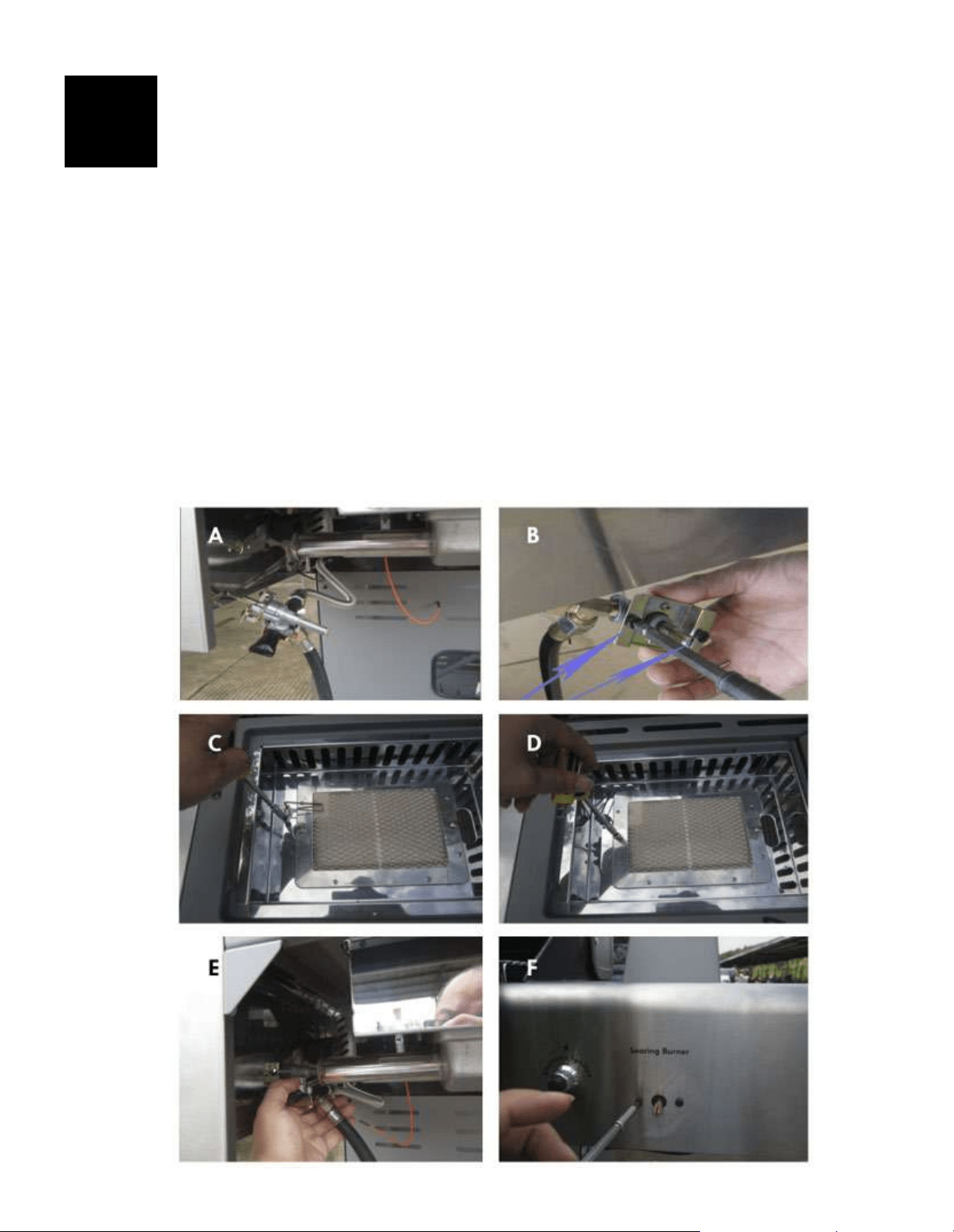
55
Quemador abrasador
Retire el empaque de plástico de la válvula del quemador abrasador. Quite la rejilla del quemador para dorar
del estante del quemador para dorar.
Retire los 2 tornillos preinstalados del vástago de control de la válvula y déjelos a un lado. (A y B)
Afloje el quemador abrasador para insertar la válvula de gas. Primero, afloje y retire el tornillo que sujeta el
electrodo (C) al estante y déjelo a un lado, luego afloje y retire los 2 tornillos que sujetan el quemador
abrasador en su lugar. (D)
Inserte la válvula de gas en el quemador abrasador. (E) Inserte el vástago de control de la válvula a través del
orificio en la fascia. (F) Instale los 2 tornillos del vástago de control de la válvula que retiró anteriormente, pero
no los apriete completamente hasta que el bisel se haya fijado a la fascia.
Vuelva a colocar el quemador abrasador en el estante con los 2 tornillos que retiró anteriormente. (G)
Vuelva a colocar el electrodo en el estante con el tornillo que retiró previamente del quemador abrasador. (H)
Inserte las aberturas del bisel sobre el vástago de control de la válvula y los 2 tornillos. (I) Deslice el bisel hacia
abajo sobre los tornillos. Asegúrese de que la marca negra en el bisel esté vertical. Apriete los 2 tornillos para
asegurar el bisel a la fascia. (J)
Empuje la perilla de control en el vástago de la válvula del quemador abrasador. (K)
Vuelva a colocar la rejilla del quemador abrasador. (L)
Conecte ambos cables del encendedor al módulo del encendedor en el lado izquierdo de la fascia del estante
del quemador abrasador. Para conectar, empuje las puntas de los cables del encendedor en las ranuras de las
clavijas en el módulo del encendedor. (M)
Deslice la caja de goteo del quemador abrasador en el soporte de la caja de goteo. (N)
Desenrosque la tapa del encendedor del panel de control. Inserte (1) batería AA (provista en el blíster) en la
ranura de la batería con el extremo positivo (+) hacia afuera. Vuelva a atornillar la tapa del encendedor en la
fascia. (O)
7
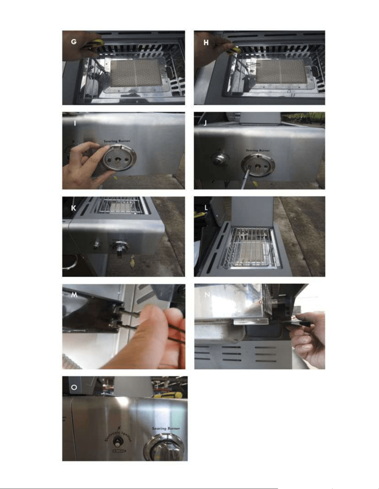
56
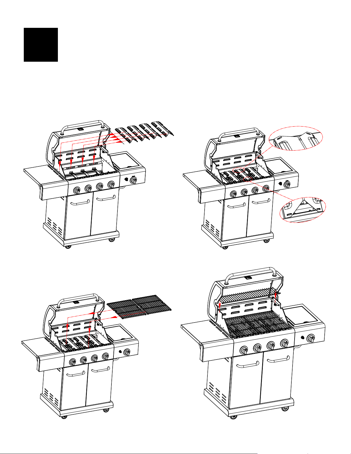
57
Difusor de calor, rejillas para cocinar y rejilla para calentar
Coloque los difusores de calor sobre los quemadores. Los difusores encajarán en la cámara de
combustión en cualquier dirección. Coloque las pestañas en el extremo frontal de la cámara de
combustión a través de las ranuras en las puntas del difusor. Coloque las puntas del difusor entre las
pestañas en la parte trasera de la cámara de combustión. (A y B)
Coloque las rejillas de cocción sobre los soportes de rejilla en la parte delantera y trasera de la
cámara de combustión. (C)
Inserte la rejilla de calentamiento en los soportes en la parte superior de la cámara de combustión
con el borde curvado hacia arriba en el frente como se muestra. (D)
8
B
C
A
D
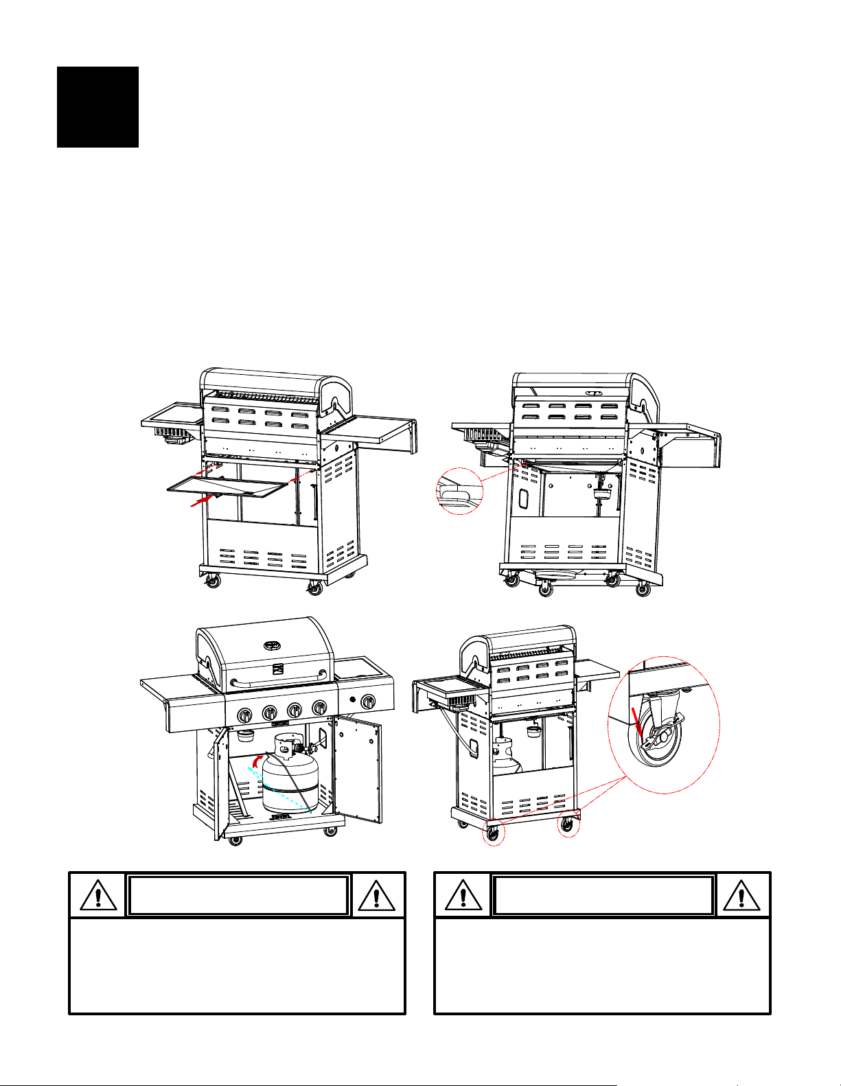
58
Bandeja de goteo, taza de goteo y tanque LP
Deslice la bandeja de goteo en la parte inferior de la cámara de combustión desde la parte posterior. (A)
Cuelgue el clip de la copa de goteo de la parte inferior de la bandeja de goteo. Asegúrese de que el
orificio de drenaje de goteo esté en el lado derecho, visto desde la parte posterior de la parrilla.
Coloque la copa de goteo en el clip de la copa de goteo. (B)
Pase la manguera del regulador a través del orificio en el panel lateral derecho. (C)
El tanque de LP se vende por separado. Úselo solo con un tanque de LP equipado con OPD (dispositivo
de protección contra sobrellenado). Llene y verifique si hay fugas antes de conectarlo a la parrilla y al
regulador.
Coloque el tanque de gas LP en el orificio del estante inferior con la abertura del cuello del tanque hacia
la derecha, como se muestra. Levante el soporte del tanque para sujetar el tanque de gas licuado de
forma segura en su lugar. (C)
Cuando la parrilla esté en la ubicación deseada, bloquee los frenos de las ruedas; esto ayudará a que la
parrilla permanezca en su lugar para una operación segura. (D)
9
Si no se instala la copa de goteo y el clip de la
copa de goteo, se producirá una caída caliente
en la parte inferior de la parrilla con riesgo de
incendio y daños a la propiedad.
PRECAUCIÓN
PRECAUCIÓN
Si no se instala correctamente el tanque,
la manguera de gas puede dañarse
durante la operación.
B
C
A
D
59
EMERGENCIAS: si no se puede detener una fuga de gas o si se produce un incendio debido a una fuga de
gas, llame al departamento de bomberos.
Problema Causa posible Prevención / solución
Fuga de gas de
mangueras
quebradas, cortadas
o quemadas.
Fuga de gas del
cilindro.
Fuga de gas de la
válvula del cilindro de
gas.
Fuga de gas entre
cilindro de gas y la
conexión del
regulador.
Sale fuego a través
del panel de control.
Hay continuamente
fuego de la grasa o
demasiadas llamas
sobre la superficie de
cocinar.
• Manguera dañada.
• Falla mecánica debido a la
oxidación o al mal uso.
• Falla de la válvula del tanque
por mal manejo o falla
mecánica.
• Instalación incorrecta,
conexión no apretada o falla
del sello de goma.
• Fuego en la sección del tubo
del quemador por
obstrucción.
• Demasiada acumulación de
goteo en la cámara de
combustión o en el área de la
bandeja de grasa.
• Apague el gas de su tanque de LP o su sistema de gas natural.
Si la manguera está agrietada o cortada pero no quemada,
simplemente reemplace la válvula/manguera/regulador.
Si la manguera está quemada, la causa podría ser otra que una
válvula/manguera/regulador defectuoso. No use la parrilla hasta
que un plomero o técnico en gas haya investigado y corregido el
problema.
• Reemplace el tanque de LP.
• Cierre la válvula del tanque de LP. Devuelva el tanque de LP al
proveedor de gas.
• Cierre la válvula del tanque de LP. Retire el regulador del tanque e
inspeccione visualmente el sello de goma en busca de daños.
Consulte la Prueba de fugas en la página 37 para obtener
instrucciones sobre cómo encontrar fugas en su regulador.
•
Cierre las perillas de control y la válvula del tanque de LP.
Deje la tapa abierta para permitir que las llamas se apaguen.
Después de que el fuego se haya apagado y la parrilla esté fría,
retire el quemador e inspeccione en busca de nidos de arañas u óxido.
Consulte las secciones Alerta de araña y Limpieza del conjunto del
quemador en la página 40 de esta Guía de uso y cuidado.
• Cierre las perillas de control y la válvula del tanque de PL. Deje la
tapa abierta para permitir que las llamas se apaguen. Después de que
la parrilla se haya enfriado, limpie las partículas de alimentos y el
exceso de goteo del interior del área de la cámara de combustión, la
bandeja de grasa y cualquier otra superficie que pueda entrar en
contacto con las partículas de alimentos y el exceso de goteo.
Problema Causa posible Prevención / solución
Los quemadores no se
encienden con el
encendedor.
(Consulte también la
Resolución de
problemas de
encendido
electrónico)
Continúa en la
siguiente página.
CUESTIONES DE GAS:
• Tratando de encender el
quemador equivocado.
• El quemador no está
conectado con la válvula de
control.
• Obstrucción en el quemador.
• Sin flujo de gas.
• La tuerca de acoplamiento y
la válvula del tanque de LP no
están completamente
conectadas.
PROBLEMAS ELÉCTRICOS:
• Electrodo agrietado o roto;
chispas en el crack.
• La punta del electrodo no está
en la posición correcta.
• Alambre y/o electrodo
cubierto con residuos de
cocción.
• Los cables están sueltos o
desconectados.
• Los cables están en
cortocircuito (chispas) entre el
encendedor y el electrodo.
• Bateria muerta.
• Lea las instrucciones en el panel de control y en la sección titulada
Uso y cuidado.
• Verifique que las válvulas estén ubicadas dentro de los tubos de los
quemadores.
• Asegúrese de que los tubos de los quemadores no estén obstruidos
con telarañas u otras materias. Consulte la sección de limpieza en la
página 40 de Uso y cuidado.
• Asegúrese de que el tanque de LP no esté vacío. Si el tanque de LP no
está vacío, consulte la sección “Caída repentina en el flujo de gas en
la página 60”.
• Desactive las perillas y desconecte la tuerca de acoplamiento del
tanque de LP. Vuelva a conectar y vuelva a intentarlo.
• Gire la tuerca de acoplamiento aproximadamente de la mitad a las
tres cuartas partes vuelta adicional hasta parada sólida.
Apriete solo a mano - no use herramientas.
• Reemplace los electrodos.
Quemadores principales:
• Las puntas del electrodo deben apuntar hacia la abertura del puerto
de gas en el quemador. La distancia debe ser de 1/8” a 1/4”.
Ajuste si es necesario.
Quemador lateral (si lo tiene)
• Las puntas del electrodo deben apuntar hacia la abertura del puerto
de gas en el quemador. La distancia debe ser de 1/8” a 3/16”.
Ajuste si es necesario.
• Limpie el cable y/o el electrodo con alcohol isopropílico con un
hisopo limpio.
• Vuelva a conectar los cables o reemplace el conjunto
electrodo/cable.
• Reemplácela con una nueva batería alcalina de tamaño AA.
Solución de problemas

60
Solución de problemas (continuación)
Problema Causa posible Prevención / solución
Los quemadores no se
encenderán con el
encendedor. (Consulte
también la Resolución de
problemas de encendido
electrónico.)
IGNICIÓN ELECTRÓNICA:
• Sin chispas, sin ruido de ignición.
• Sin chispas, algún ruido de ignición.
• Chispas, pero no en el electrodo o
en su totalidad fuerza.
• Vea la sección I del sistema de encendido electrónico.
• Consulte la Sección II del Sistema de encendido electrónico.
• Consulte la Sección III del Sistema de encendido electrónico.
Los quemadores no se
encienden con fósforos.
• Vea "PROBLEMAS DE GAS:" en la
página anterior.
• El partido no llegará.
• Método incorrecto de iluminación
de partidos.
• Use un fósforo de tallo largo (fósforo de chimenea).
• Consulte la sección “Encendido con fósforos” en la página 39
de Uso y cuidado.
Caída repentina de gas
flujo o baja llama
• Sin gasolina.
• Se disparó la válvula de exceso de
flujo.
• Consulte la Sección III del Sistema
de encendido electrónico
• Verifique si hay gas en el tanque de LP.
• Apague las perillas, espere 30 segundos y encienda la parrilla.
Si las llamas aún son bajas, cierre las perillas y la válvula del
tanque de LP. Desconecte el regulador. Vuelva a conectar el
regulador y realice una prueba de fugas. Abra la válvula del
tanque de LP, espere 30 segundos y luego encienda la parrilla.
• Desactive las perillas y la válvula del tanque de LP. Desconecte
la tuerca de acoplamiento del cilindro. Vuelva a conectar y
vuelva a intentarlo.
Las llamas se apagan. • Vientos altos o racheados.
• Bajo en gas LP.
• Se disparó la válvula de exceso de
flujo.
• Gire la parrilla para que el frente de la parrilla mire hacia el
viento o aumente la altura de la llama.
• Vuelva a llenar el tanque de LP.
• Consulte la sección anterior "Caída repentina en el flujo de
gas".
Estallar. • Acumulación de goteo.
• Grasa excesiva en la carne.
• Temperatura de cocción excesiva.
• Limpie los quemadores y el interior de la parrilla / cámara de
combustión.
• Recorte la grasa de la carne antes de asar a la parrilla.
• Ajuste a una temperatura más baja.
Persistente goteo de
fuego.
• Goteo atrapado por la
acumulación de alimentos
alrededor del sistema de la hornilla.
• Gire las perillas a APAGADO. Apague el gas en el tanque de
LP. Deje la tapa en su lugar y deje que el fuego se apague.
Después de que la parrilla se enfríe, retire y limpie todas las
piezas.
Escena retrospectiva…
(fuego en el (los) tubo (s)
del quemador).
• Los quemadores y / o los tubos del
quemador están bloqueados.
• Gire las perillas a APAGADO. Limpie el quemador y/o los
tubos del quemador. Consulte la sección de limpieza del
quemador en la página 40 de Uso y cuidado.
No se puede completar LP
cilindro.
• Bloqueo de vapor en la tuerca de
acoplamiento / conexión del
cilindro LP .
• Some dealers have older fill nozzles
with worn threads.
• Consulte la sección "Uso de iluminación" de la sección Uso y
cuidado.
Un quemador no se
enciende desde otro
quemador (s).
• Colocación de goteo o partículas
de alimentos en el (los) extremo (s)
del tubo (s) de arrastre.
• Limpie los tubos de arrastre con un cepillo de alambre.

61
Solución de problemas – Encendido electrónico
Problema Causa posible Procedimiento de revisión Prevención / solución
SECCIÓN I
No aparecen
chispas en ninguno
de los electrodos
cuando la perilla de
control se gira a HI:
no se escucha ningún
ruido del módulo de
chispas.
• La pila no está
instalada
adecuadamente.
• Pila gastada.
• El conjunto de cables
no está instalado
correctamente.
• Módulo de chispas
defectuoso.
• Compruebe que la batería
tiene el lado positivo hacia el
exterior.
• ¿Se ha usado la batería
anteriormente?
• Verifique para asegurarse de
que las roscas estén
correctamente enganchadas.
• Si no se generan chispas con
la batería nueva y los cables
están conectados
correctamente, el módulo
está defectuoso.
• Instale la batería, asegurándose de que el extremo
positivo esté hacia afuera y el extremo negativo
hacia adentro.
• Reemplace la batería con una nueva batería
alcalina de tamaño AA.
• Desenrosque el conjunto del módulo de encendido
y asegúrese de que todos los cables estén
instalados correctamente antes de volver a instalar
el conjunto del módulo de encendido.
• Reemplace el conjunto del módulo de encendido
llamando al servicio de atención al cliente al
1-888-287-0735.
SECCIÓN II
No aparecen
chispas en ningún
electrodo cuando la
perilla de control se
gira a HI; el ruido se
puede escuchar
desde el módulo de
chispa.
• Los electrodos no
están conectados
correctamente.
• ¿Están bien conectados los
electrodos?
• Retire y vuelva a conectar todos los cables de los
electrodos de los enchufes del módulo.
SECCIÓN III
Hay chispas pero no
en todos los
electrodos y/o no a
plena potencia.
• Los electrodos no
están conectados
correctamente.
• Arco eléctrico entre
los cables de salida y
el tubo del quemador.
• Batería débil.
• Los electrodos están
húmedos.
• Los electrodos están
agrietados o rotos;
chispas aparecen
donde agrietado.
• ¿Están bien conectados los
electrodos?
• Si es posible, observe la
parrilla en un lugar oscuro.
Opere el sistema de
encendido y busque arcos
entre los cables de salida y
el tubo del quemador.
• Todas las chispas están
presentes pero tienen un
ritmo débil o lento.
• ¿Se ha acumulado humedad
en el electrodo y/o en los
puertos del quemador?
• Inspeccione los electrodos en
busca de grietas.
• Retire y vuelva a conectar todos los cables de los
electrodos de los enchufes del módulo.
• Si se ven chispas en lugares que no sean el área del
tubo del quemador, el aislamiento del cable puede
estar dañado. Reemplace los cables.
• Reemplace la batería con una nueva batería
alcalina de tamaño AA.
• Use una toalla de papel para eliminar la humedad.
• Reemplace los electrodos agrietados o rotos
llamando al servicio de atención al cliente al
1-888-287-0735.
SECCIÓN IV
La parrilla no se
calienta y solo
alcanza los 250-300
grados
• Esto generalmente
ocurre cuando
enciende las perillas
de control antes de
encender la válvula
del tanque de LP. Si es
así, esto activará el
dispositivo de
seguridad del
regulador de gas, la
parrilla solo alcanzará
temperaturas entre
250 y 300F incluso con
todos los quemadores
en la configuración
alta.
• ¿Está el regulador encendido
y apretado?
• Asegúrese de que el
regulador esté conectado
correctamente al tanque y
que las perillas de control
estén en la posición de
apagado.
• Abra la tapa de la parrilla.
• Apague todas las perillas en el panel de control.
• Apague la perilla del tanque.
• Desconecte el regulador del tanque de LP. Espere
30 segundos.
• Vuelva a conectar el regulador al tanque de LP.
Abra lentamente la perilla del tanque de LP hasta el
final.
• No ejerza demasiada fuerza sobre la válvula
cuando esté en la posición completamente abierta
para evitar dañar la válvula.
• Encienda la perilla de control apropiada y
encienda la parrilla según las instrucciones de
encendido en la página 39.