
Loading ...
Loading ...
Loading ...
Battery wire and ground wire size
Wire length Wire size
less than 2.2 m (7 ft
3 in.)
8 AWG
less than 3.6 m (11 ft
10 in.)
6 AWG
less than 6.4 m (20 ft
12 in.)
4 AWG
1 Route battery wire from engine com-
partment to the vehicle interior.
! When drilling a cable pass-hole into the ve-
hicle body and routing a battery wire thor-
ough it, take care not to short-circuit the
wire damaging it by the cut edges or burrs
of the hole.
After completing all other amplifier connec-
tions, finally connect the battery wire terminal
of the amplifier to the positive + battery term-
inal.
2
1
3
1 Positive + terminal
2 Batter y wire (sold separately)
The maximum length of the wire between
the fuse and the positive + terminal of the
battery is 30 cm (12 in.).
3 Fuse (100 A) (sold separately)
Each amplifier must be separately fused at
100 A.
2 Use wire cutters or a utility knife to
strip the end of the battery wire, ground
wire and system remote control wire to ex-
pose about 10 mm (3/8 in.) of the end of
each of the wires, and then twist the ex-
posed ends of the wires.
Twist
10 mm (3/8 in.)
3 Connect the wires to the terminal.
Fix the wires securely with the terminal
screws.
4
6
7
2
1
5
3
1 Batter y wire
2 Power terminal
3 Ground wire
4 Ground terminal
5 System remote control wire
6 System remote control terminal
7 Terminal screws
<5707000013140V>13
En
Connecting the units
Connecting the speaker/
subwoofer output terminals
1 Use wire cutters or a utility knife to
strip the end of the speaker/subwoofer
wires to expose about 10 mm (3/8 in.) of
wire and then twist the wire.
Twist
10 mm (3/8 in.)
2 Connect the speaker/subwoofer wires
to the speaker/subwoofer output term-
inals.
Fix the wires securely with the terminal
screws.
1
3
2
1
5
4
1 Terminal screws
Tighten the screws with a 1.5 mm (1/8 in.)
hexagonal wrench for terminal screws of
the speaker and a 3 mm (1/8 in.) hexagonal
wrench for terminal screws of the subwoo-
fer.
2 Speaker wires
3 Speaker output terminals
4 Subwoofer wires
5 Subwoofer output terminals
Before installing the amplifier
WARNING
! To ensure proper installation, use the supplied
parts in the manner specified. If any parts
other than those supplied are used, they may
damage internal parts of the amplifier, or be-
come loose causing the amplifier to shut
down.
! Do not install in:
— Places where it could injure the driver or
passengers if the vehicle stops suddenly.
— Places where it may inter fere with the dri-
ver, such as on the floor in front of the dri-
ver’s seat.
! Install tapping screws in such a way that the
screw tip does not touch any wire. This is im-
portant to prevent wires from being cut by vi-
bration of the car, which can result in fire.
! Make sure that wires do not get caught in the
sliding mechanism of the seats or touch the
legs of a person in the vehicle as short-circuit
may result.
! When drilling to install the amplifier, always
confirm no parts are behind the panel and
protect all cables and important equipment
(e.g. fuel/brake lines, wiring) from damage.
CAUTION
! To ensure proper heat dissipation of the ampli-
fier, ensure the following during installation:
— Allow adequate space above the amplifier
for proper ventilation.
— Do not cover the amplifier with a floor mat
or carpet.
! Place all cables away from hot places, such
as near the heater outlet.
! The optimal installation location differs de-
pending on the car model. Secure the ampli-
fier at a sufficiently rigid location.
! Check all connections and systems before
final installation.
! After installing the amplifier, confirm that the
spare tire, jack and tools can be easily re-
moved.
<5707000013140V>14
En
Connecting the units Installation
Attaching the Bass boost
remote control
Attach with tapping screws (3 mm × 10 mm
(1/8 in. × 3/8 in.)) at an easily accessible loca-
tion such as under the dashboard.
Tapping screws (3 mm × 10 mm (1/8 in. × 3/8 in.))
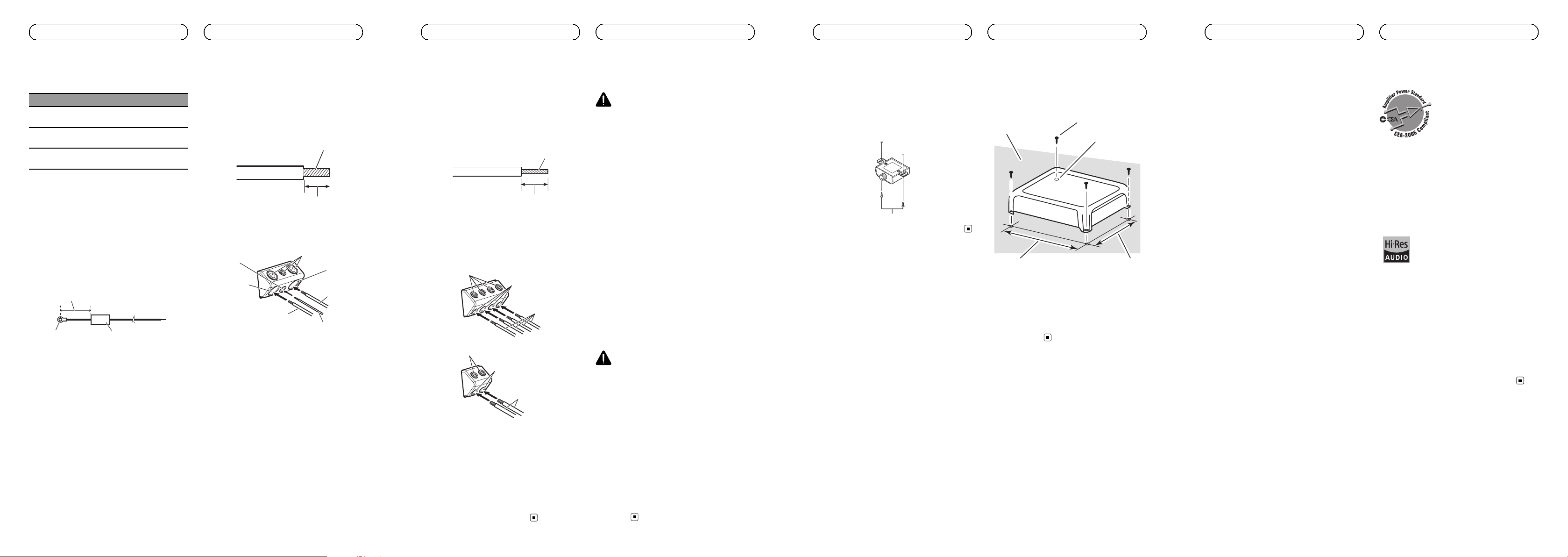
Example of installation on
the floor mat or chassis
1 Place the amplifier in the desired instal-
lation location.
Insert the supplied tapping screws (4 mm ×
18 mm (1/8 in. × 3/4 in.)) into the screw holes
and push on the screws with a screwdriver so
they make an imprint where the installation
holes are to be located.
2 Drill 2.5 mm (1/8 in.) diameter holes at
the imprints either on the carpet or directly
on the chassis.
3 Install the amplifier with the use of
supplied tapping screws (4 mm × 18 mm
(1/8 in. × 3/4 in.)).
1
2
3
45
1 Tapping-screws (4 mm × 18 mm (1/8 in. ×
3/4 in.))
2 Drill a 2.5 mm (1/8 in.) diameter hole
3 Floor mat or chassis
4 Hole-to-hole distance: 279.5 mm (11 in.)
5 Hole-to-hole distance: 191.5 mm
(7-17/32 in.)
<5707000013140V>15
En
Installation
Specifications
Power source ............................. 14.4 V DC (10.8 V to 15.1 V
allowable)
Grounding system ................... Negative type
Current consumption ............ 55 A (at continuous power,
4 W)
Average current consumption
..................................................... 5.2 A (4 W)
Fuse ................................................ 30 A × 3
Dimensions (W × H × D) ...302mm × 60 mm ×
215 mm
(11-7/8 in. × 2-3/8 in. ×
8-1/2 in.)
Weight .......................................... 3.3 kg (7.3 lbs)
(Leads for wiring not in-
cluded)
Maximum power output ....... 150 W × 4 + 700 W (4 W)/
TOTAL 2 000 W
Continuous power output ... 75 W × 4 + 350 W (at 14.4 V,
4 W)
200 W × 2 + 350 W (at
14.4 V, 4 W)
100 W × 4 + 600 W (at
14.4 V, 2 W)
Load impedance ...................... 4 W (2 W to 8 W allowable)
Frequency response:
A/B CH:10 Hz to 50 kHz
SUB CH:10 Hz to 500 Hz
Signal-to-noise ratio ............... 94 dB (IEC-A network)
Distortion ..................................... 0.05 % (10 W, 1 kHz)
Low pass filter:
(A/B CH)
Cut off frequency ........... 40 Hz to 500 Hz
Cut off slope ..................... –12 dB/oct
(SW)
Cut off frequency ........... 40 Hz to 500 Hz
Cut off slope ..................... –12 dB/oct, –24 dB/oct
High pass filter:
(A/B CH)
Cut off frequency ........... 40 Hz to 500 Hz
Cut off slope ..................... –12 dB/oct
Bass boost:
(SW)
Frequency .......................... 50 Hz
Level ..................................... 0 dB to 18 dB
Gain control:
RCA ...................................... 200 mV to 6.5 V
Speaker .............................. 0.8 V to 16 V
Maximum input level / impedance:
RCA ...................................... 6.5 V / 25 kW
Speaker .............................. 16 V / 12 kW
CEA2006 Specifications
Power output ............................. 75 W RMS × 4 + 350 W x 1
RMS ( 4 W and ≦ 1 % THD
+N)
S/N ratio ....................................... 75 dBA (reference: 1 W into
4 W)
GM-DX975
In order to listen to music with Hi-Res sound quality. all
components complied with High-Resolution Audio Stan-
dard of Japan Audio Society are recommended to use.
The product with this logo is conformed to High-Resolu-
tion Audio standard defined by Japan Audio Society.
This logo is used under license from Japan Audio So-
ciety.
Notes
! Specifications and the design are subject to
modifications without notice.
! The average current consumption is nearly
the maximum current consumption by this
unit when an audio signal is input. Use this
value when working out total current con-
sumption by multiple power amplifiers.
<5707000013140V>16
En
Additional information
Loading ...
Loading ...
Loading ...