Loading ...
Loading ...
Loading ...
8
ASSEMBLY INSTRUCTIONS (CONTINUED)
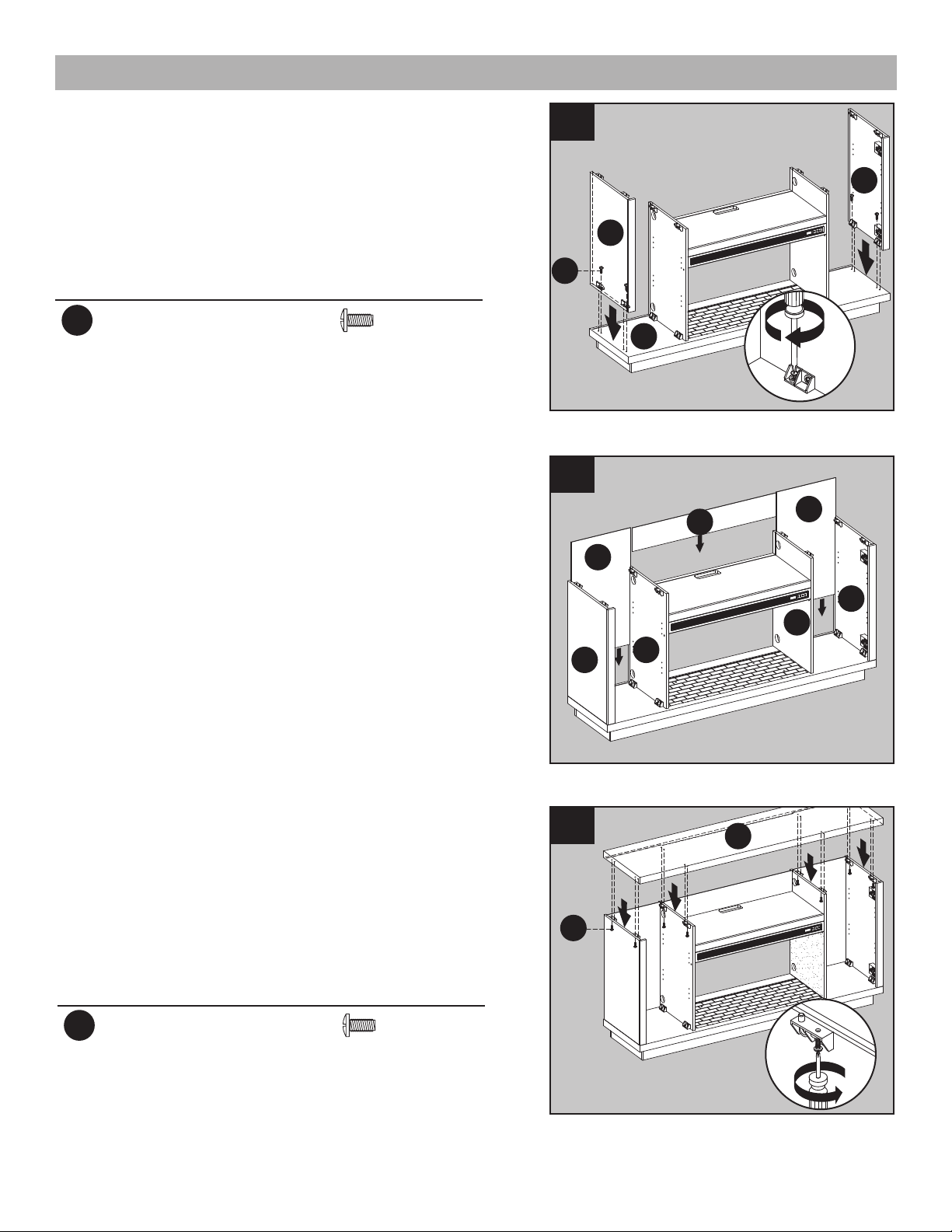
3. Attach right outer wall (F) to the right side of
base (S), Securing with two bolts (AA).
Repeat for left outer wall (E).
Hardware Used
AA
Bolt
x 4
3
1
1
E
F
S
AA
2
4. As shown in the diagram, insert the center back
panel (J) and back panels (K) along the grooves
of the middle walls (C,D) and outer walls (E,F).
4
K
K
J
C
E
D
F
5. Attach top (A), Securing from underneath with
eight bolts (AA).
Hardware Used
AA
Bolt
x 8
A
1
1
1
1
AA
5
2
Loading ...
Loading ...
Loading ...