Loading ...
Loading ...
3
Installation
Note:
1. Test to make sure the entire installation works properly before pulling cables
through ceilings/walls.
2. To achieve maximum distance and performance, 24 AWG solid-wire Cat5e/6
cable must be used. The use of stranded-wire Cat5e/6 cable or cable with a
gauge size higher than 24 AWG will result in a shorter extension distance. All
TRIPP LITE N202-Series Cat6 cables are made with 24 AWG solid-wire cabling.
3. Make sure the power to all connected devices is turned off prior to installation.
1
4
3
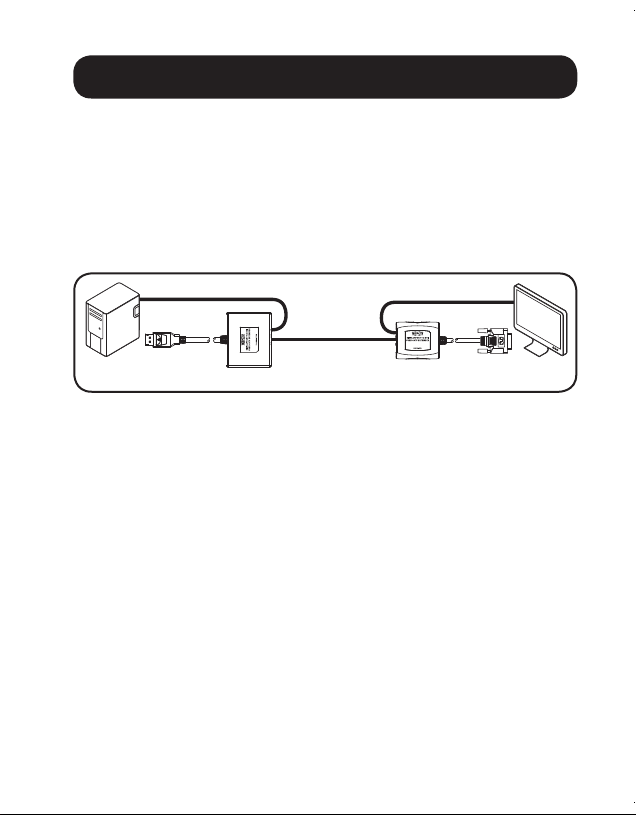
24 AWG SOLID-WIRE
CAT5/6 CABLE
DISPLAYPORT
COMPUTER
DVI
DISPLAY
Up to 125 ft. at 1920 x 1080 (1080p) @ 60 Hz
2
5
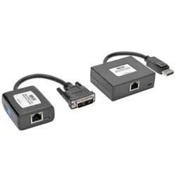
1. Connect the transmitter unit’s built-in DisplayPort cable to the
computer’s DisplayPort output port.
2. Connect the included USB Micro-B cable to the transmitter unit and a
USB port on the computer or a USB wall outlet. The green and orange
LEDs on the transmitter unit’s RJ45 ports will illuminate to indicate it is
receiving power from the USB Micro-B cable.
3. Connect the RJ45 port on the transmitter to the RJ45 port on the
receiver using Cat5e/6 cable.
Note: See the installation diagrams for maximum extension distance and video
resolutions.
4.
Connect the receiver unit’s built-in DVI cable to a DVI monitor input port.
5. Connect the included USB Micro-B cable to the receiver unit and a
USB port on the display or a USB wall outlet. The green LED on the
receiver’s RJ45 port will illuminate to indicate it is receiving power from
the USB Micro-B cable.
15-11-118-933506-EN.indd 3 11/13/2015 2:29:39 PM
Loading ...
Loading ...
Loading ...