
Loading ...
Loading ...
Loading ...
ENGLISH
9
OPERATION
WARNING: To reduce the risk of serious personal
injury, turn unit off and remove the battery pack
before making any adjustments or removing/
installing attachments or accessories. An
accidental start-up can causeinjury.
Installing and Removing the Battery Pack
(Fig. D)
NOTE: For best results, make sure your battery pack is
fullycharged.
To install the battery pack
3
into the tool handle, align the
battery pack with the rails inside the tool’s handle and slide
it into the handle until the battery pack is firmly seated in
the tool and ensure that it does notdisengage.
To remove the battery pack from the tool, press the release
button
13
and firmly pull the battery pack out of the tool
handle. Insert it into the charger as described in the charger
section of thismanual.
Fig. D
13
3
Worklight (Fig. A)
CAUTION: Do not stare into worklight. Serious eye
injury could result.
There is a worklight
15
located just below the blade lock
button
11
. The worklight is activated when the trigger
switch is depressed, and will automatically turn off 20
seconds after the trigger switch is released. If the trigger
switch remains depressed, the worklight will remain on.
NOTE: The worklight is for lighting the immediate work
surface and is not intended to be used as a flashlight.
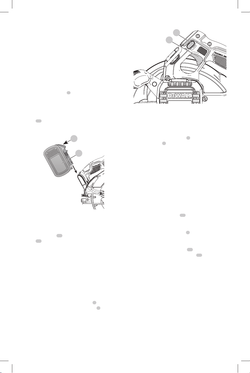
Trigger Switch (Fig. E)
WARNING: This tool has no provision to lock the
trigger switch in the ON position and should never be
locked ON by any other means.
Release the trigger switch lock-off button
1
by pressing
the button as shown. Pull the trigger switch
2
to turn the
motor on. Releasing the trigger switch turns the motor off.
Fig. E
2
1
Changing Blades (Fig. F, G, H)
WARNING: Remove battery from tool before
changing blades.
To install the Blade (Fig. F, G, H)
1. Retract the lower blade guard
7
using the lower blade
retracting lever
6
and place the blade on the saw
spindle against the inner clamp washer, making sure
that the blade will rotate in the proper direction (the
direction of the rotation arrow on the saw blade and the
teeth must point in the same direction as the direction
of rotation arrow on the lower blade guard). Do not
assume that the printing on the blade will always be
facing you when properly installed. When retracting
the lower blade guard to install the blade, check the
condition and operation of the lower blade guard to
assure that it is working properly. Make sure it moves
freely and does not touch the blade or any other part, in
all angles and depths of cut.
2. Place outer clamp washer
16
on saw spindle with the
large flat surface against the blade with beveled side
facing out.
3. Thread blade clamping screw
8
into saw spindle by
hand (screw has right-hand threads and must be turned
clockwise to tighten).
4. Depress the blade lock button
11
while turning the
saw spindle with the blade wrench (
14
, Fig. G, H) until
the blade lock engages and the blade stops rotating.
5. Tighten the blade clamping screw firmly with the blade
wrench.
NOTE: Never engage the blade lock while saw is running,
or engage in an effort to stop the tool. Never turn the saw
on while the blade lock is engaged. Serious damage to your
saw will result.
Loading ...
Loading ...
Loading ...