Owners Manual
2
Contents:
1. Contents of Rower Pack.
2. Assembly Instructions.
3. Tank Filling and Water Treatment.
4. Changing Tank Water
5. Rower Computer.
6. Replacing Rower Belt.
7. Replacing Bungee Cord.
8. Maintenance and Troubleshooting.
9. Parts List/Exploded Diagram.
10. Warranty.
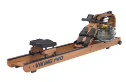
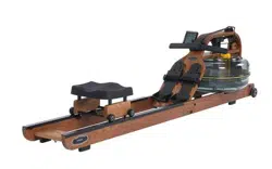
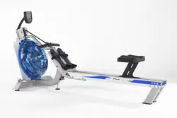
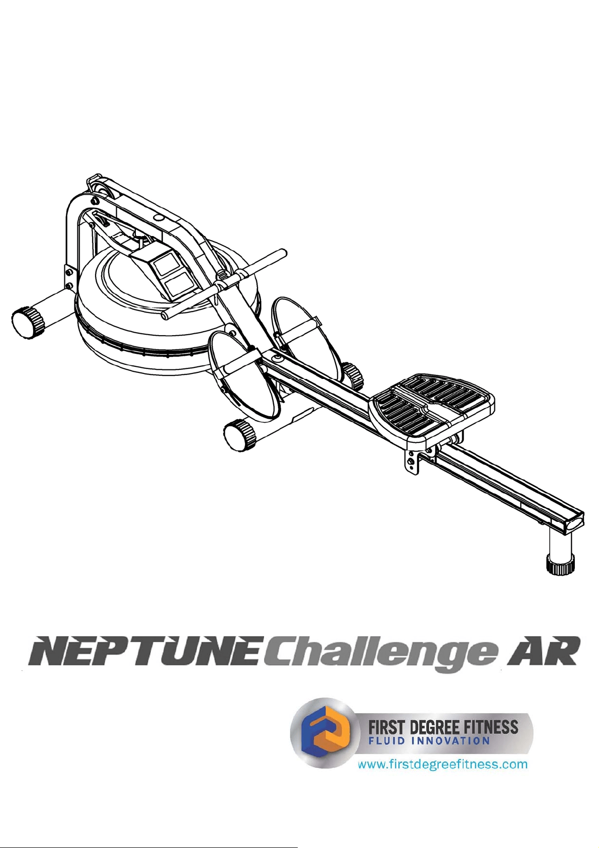
Training with the Neptune Challenge AR Rower
1. As with any piece of fitness equipment, consult a physician before beginning your Neptune
Challenge AR Rower exercise program.
2. Follow instructions provided in this manual for correct foot position and basic rowing tech-
niques.
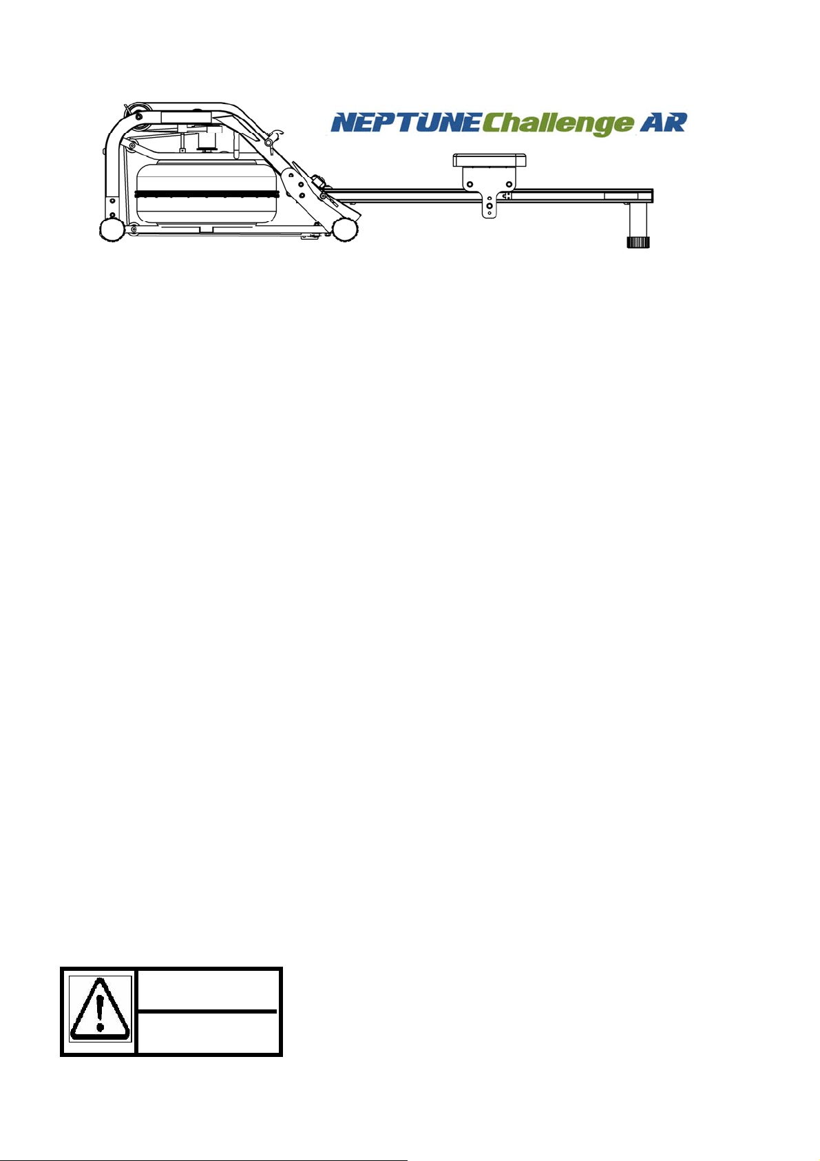
1. The Neptune Challenge AR Rower can stand vertically for
storage. Make sure a secure location is chosen, such as the
corner of a room or against a wall.
2. Keep hands and fingers away from moving parts, as indicated
by the warning sticker on the mainframe of your machine.
CAUTION
3
Contents:
Filling Siphon
22
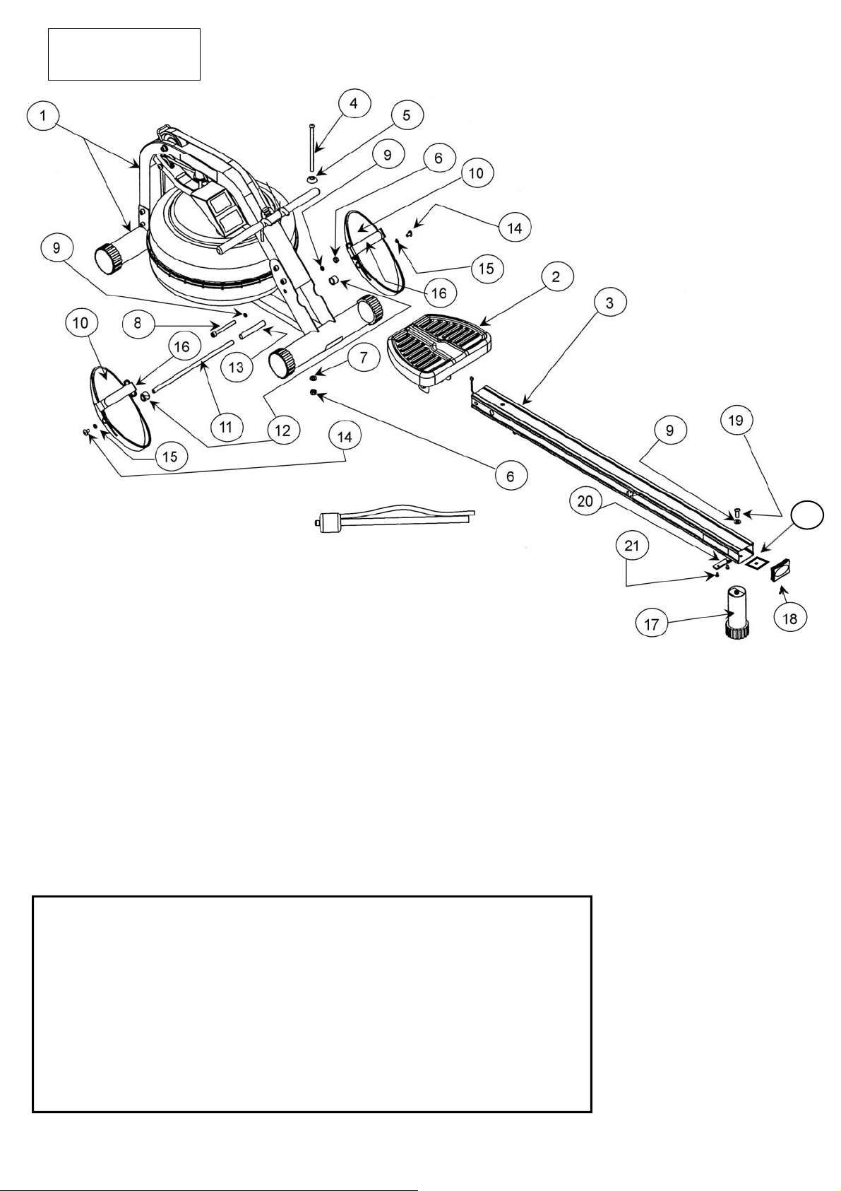
The Main box, seat rail box and parts kit will contain the following items
1. Main Frame.
2. Rower Seat
3. Seat Rail (boxed separately)
4. M10x180mm Bolt (1).
5. M10 Plastic Dome Washer (1).
6. M10 Nylock Nut (2).
7. M10 Washer (1).
8. M10x95mm Bolt (1).
9. 11x21x2T Washer (3)
10. Footplate (2)
11. 12mmx388mm Footplate Shaft (1)
12. Nylon Footplate Spacer (2)
13. 17mmx1.5Tx110 Internal Spacer(1)
14. M8x15mm Bolt (2)
15. M8 Washer (2)
16. Footstrap (2)
17. Rear Leg (1)
18. 75x50 Rubber End Cap (1)
19. M10x25 Rear Leg Bolt (1)
20. Rear Rubber Bumpstop (1)
21. M6x10mm Bumpstop Screws (2)
22. Seat Rail Internal Support Bracket (1)
Tool Kit and Water Treatment (Not pictured) which includes:
1. Multi-Tool (1)
2. 6mm Allen Key (2)
3. 8mm Allen Key (1)
4. 4x Chlorine Treatment Tablets
5. Owners Manual
6. 2x AA Batteries
4
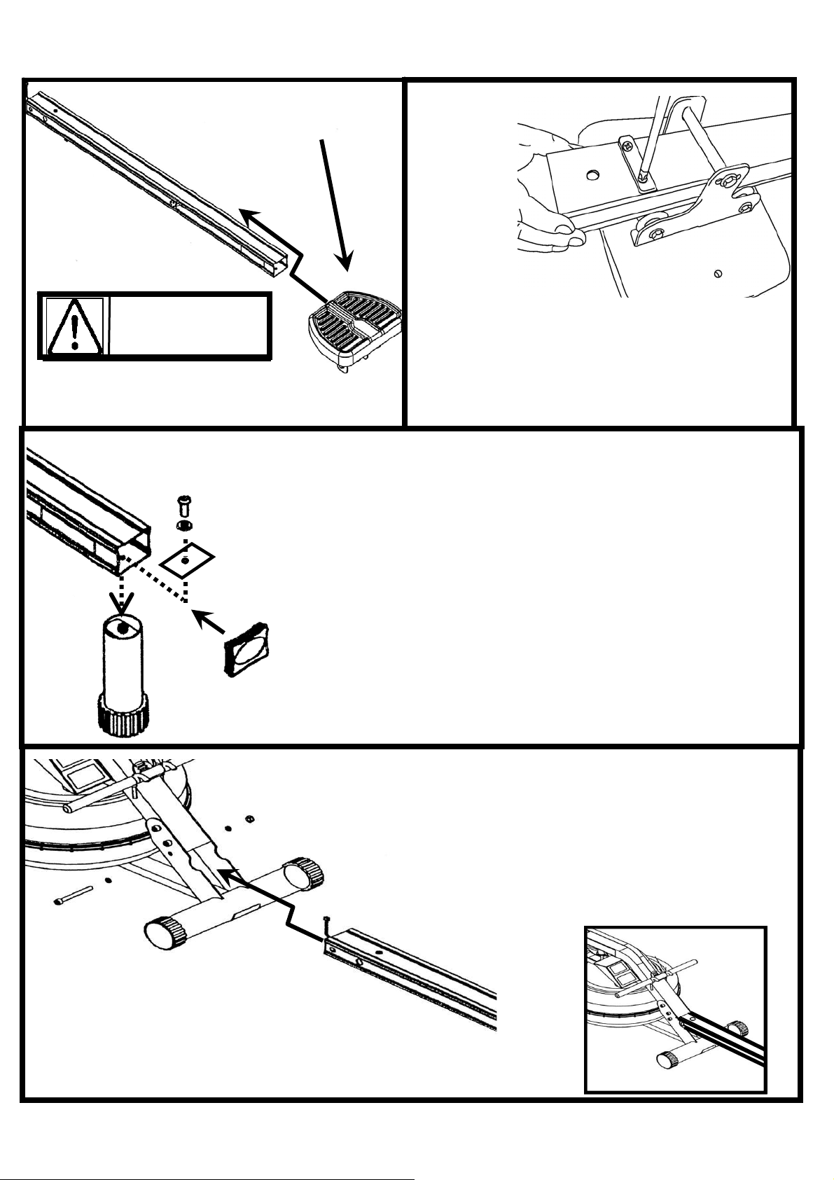
Assembly Instructions:
Install Rower Seat onto Seat
Rail, with widest part of seat
rearward.
Step 1
Turn Seat Rail over, and install the Rear Rubber
Bumpstop using 2x M6x10mm screws with bev-
eled edge facing forward.
Step 2
CAUTION
Installing the Seat incorrectly will result in lack of
data pickup during rowing.
Step 3
Rear Rubber End Cap
Seat Rail Internal Support
Bracket
Rear Leg
Seat Rail
M10x25mm Bolt and
11x21x2 Washer
Using the M10x25mm Bolt,
11x21x2T Washer, Seat Rail Internal
Support Bracket and Rear Leg, in-
stall as shown. Once Rear Leg is
tightened, install the Rear Rubber
End Cap.
M10 Nylock Nut and
11x21x2T Washer
M10x95mm
Bolt and
11x21x2T
Washer
Sensor Lead
Step 4: Install the Seat Rail onto the
Mainframe. Attach Sensor Lead from
Seat Rail to the Mainframe, then align
the front Seat Rail holes with Main-
frame and install, using 1x M10x85mm
Bolt, 2x 11x21x2T Washers and 1xM10
Nylock Nut.
5
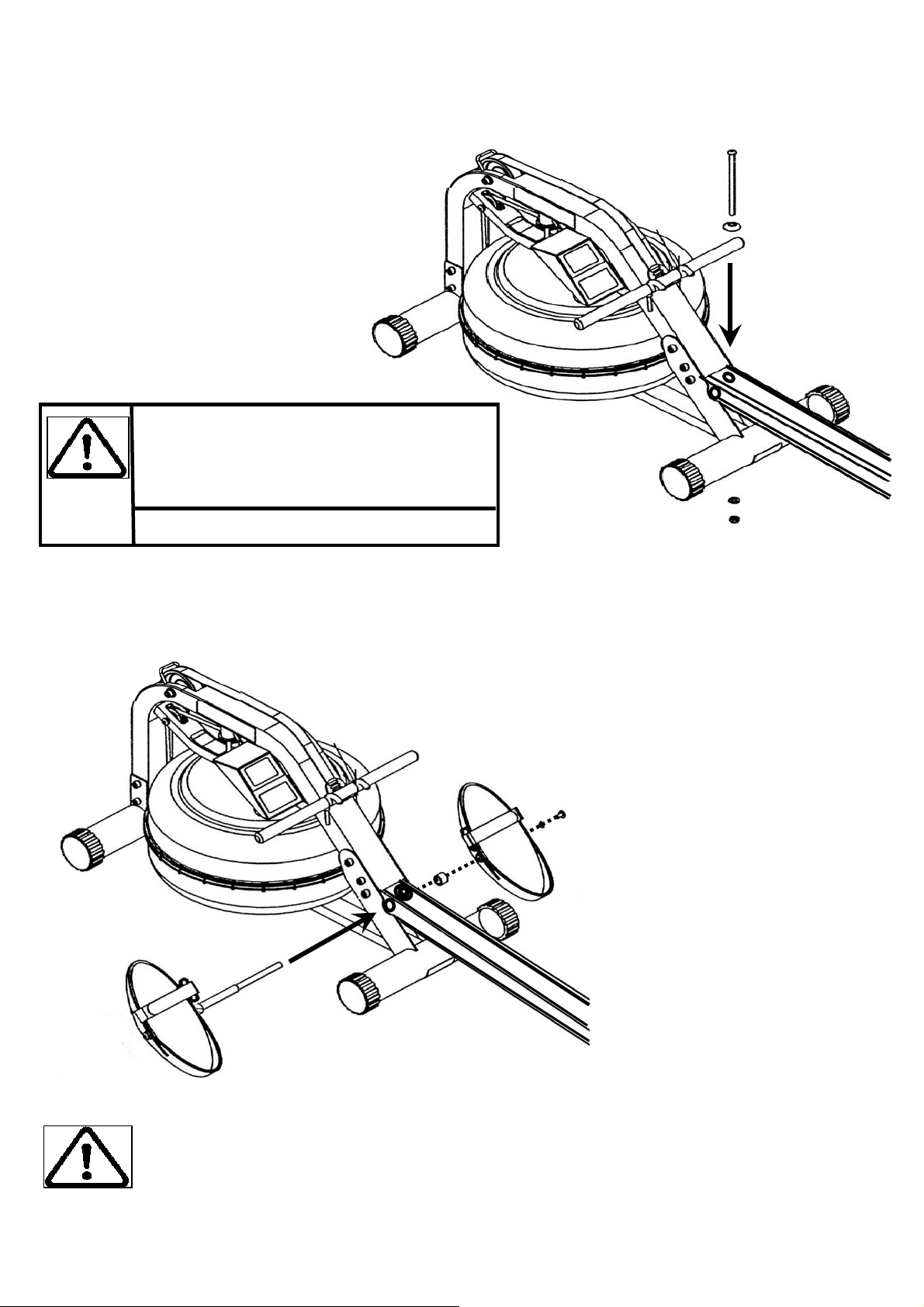
M10x180mm Bolt and Plastic
Dome Cap
M10 Washer and
Nylock Nut
Step 5: Install the M10x180mm Vertical
Frame Tensioning Bolt with the Plastic Dome
Cap through the top of the Seat Rail and se-
cure from underneath with M10 Washer and
Nylock Nut.
Assembly Instructions:
Note: Do not tighten the Vertical
Frame Tensioning Bolt. See the “Fine
Tuning Your Rower” page for details
once assembly is complete
Tip: When mounting the Footplate assembly onto the rower, it is only necessary to
remove one side, and leave the other intact as shown here.
Note: 2 Allen keys of the same size are provided for this portion of the assembly.
Step 6: Install the Footplate onto the Rower.
Footplate assembly left side. For
ease of assembly, leave the left side
of the Footplate and Seat Rail Spacer
in place as shown.
6
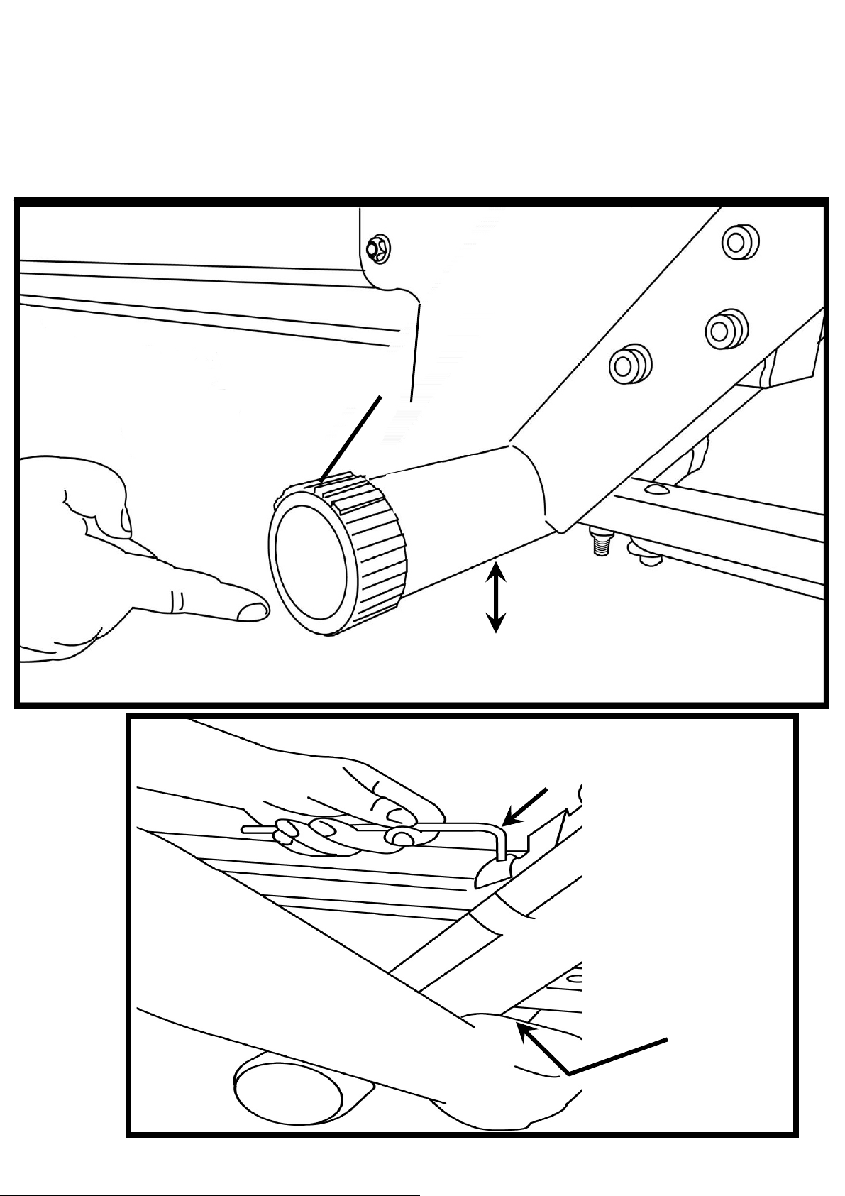
Fine Tuning the Neptune Challenge AR: The Neptune Challenge AR is
designed to function as a pre-stressed frame . Using the Mid Leg as your guideline, tighten the Vertical
Frame Tensioning Bolt until the Mid Leg rises approximately 3-5mm off the floor. The Mid Leg should
just touch the ground during a rowing stroke.
Mid Leg
3-5mm off the floor is ideal
And with the Multi-Tool
here:
Adjust Vertical Frame Tensioning Bolt here using
the Allen Key here:
7
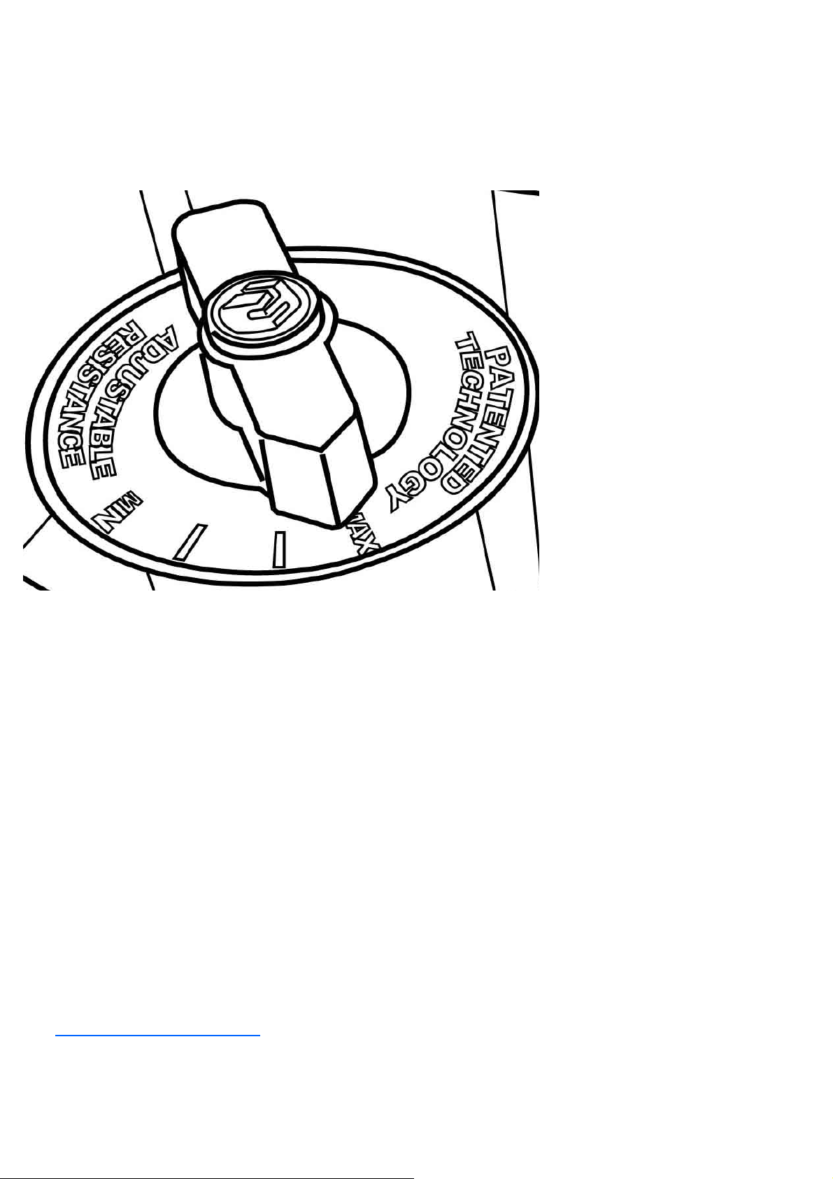
MAX: This setting allows the
maximum amount of water to
reach the flywheel for heaviest
resistance
———
———
MIN: Keeps a portion of the
water in reserve creating light
resistance.
Adjustable Resistance (AR) Tank:
The Adjustable Resistance (AR) Tank, developed and patented by First Degree Fitness, offers a
true multi-level experience. Water is moved between the "storage" and "active" chambers of the AR
Tank. Your new Rowing Ergometer can adapt - at the turn of a dial - to the resistance preferred by
each user in the home environment.
To achieve minimum resistance, select "MIN" on the tank adjuster. It takes 10 strokes to fill the
central (storage) tank, leaving a minimal amount of water in the outer (active) tank. This process
is always required if minimum resistance is desired. Row hard at a steady pace (20 to 25 strokes
per minute [SPM]) and put some effort into the stroke, ensuring that good form is maintained. You
can make adjustments to the resistance level while you row. Your Rowing Ergometer will adapt
almost instantly to increases in resistance but will take up to 10 strokes to reduce the effort re-
quired, as the central (storage) tank fills up.
GETTING STARTED
Once you have found a level that gives you the exercise required, changes can be made to
SPM and to stroke intensity to further vary your energy input. Interval training is used by most
Rowers, where a period of low intensity is combined with short intervals of high intensity. Your
FDF Rowing Ergometer allows for changes 'on the fly', to achieve multi-level resistance profiles
during a single workout. For more information on exercise routines, please visit our website at
www.firstdegreefitness.com
DEVELOPING YOUR ROUTINE
8
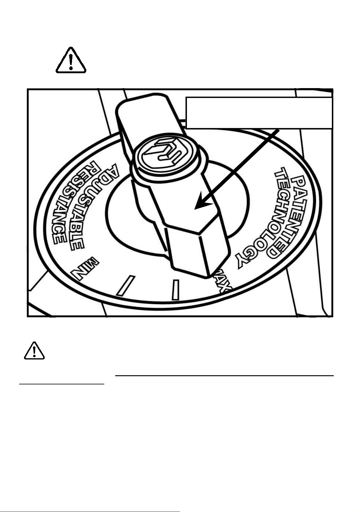
Note on Filling the AR Tank:
Caution:
When filling the A/R tank, the adjuster handle must be set to the “MAX” position as shown to
allow accurate fill levels.
Using any other setting other than “MAX” will result in inaccurate fill levels and in extreme cases
could cause leakage to occur during use or when stored in the standing position.
DO NOT overfill the tank beyond the maximum indicated level of 17 litres. Refer to the Tank Level
Decal on the lower side of the tank
Important: Please Read before filling
tank:
Set adjuster knob to “MAX”
prior to filling
9
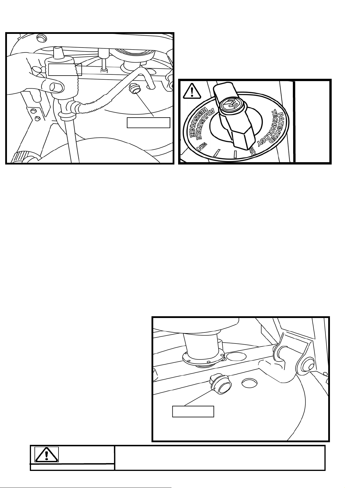
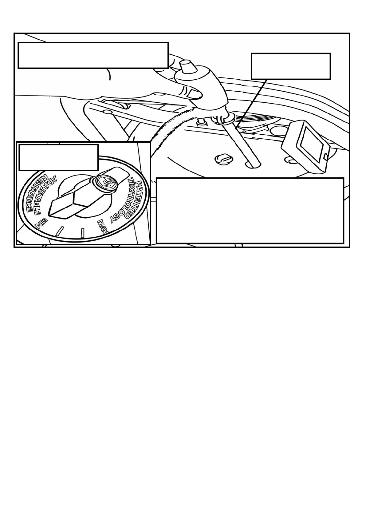
1. Remove rubber fill plug from the top of the tank.
2. Place a large bucket of water next to the Neptune Challenge AR and position siphon with the rigid
hose in the bucket and the flexible hose into the tank as shown. Note: Make sure small breather
valve on the top of the siphon is closed before filling.
Note: Where water quality is known to be poor, FDF recommends the use of distilled water.
3. Begin filling tank by squeezing siphon. Use Level Gauge decal on side of tank to measure volume
of water in tank. Important: Fill tank only with adjuster dial set to “MAX”. Do not overfill tank!
4. After filling tank to the desired water level, open the valve on the top of the siphon to allow excess
water to escape.
5. Ensure that tank plug is replaced once filling and water treatment procedures are complete.
Tips on Siphon use: Putting the fill bucket higher than the tank will allow the siphon to "self-pump"
when adding water to the tank.
Tank Filling and Water Treatment:
Tank plug
Siphon
Tank Filling and Water Treat-
ment Procedures
Note: 17 liters of water is required for
maximum filling.
Fill tank
with
adjuster
handle set
to “Max”
only.
Tank Plug
Use a drop cloth under the tank both when filling the tank to avoid
staining floor or carpet
Caution:
Water Treatment Procedures:
1. Add Chlorine tablet.
2. Enough Chlorine Tablets are supplied
for many years of Water treatment. Add
a chlorine Tablet whenever the
Water appears dirty or cloudy.
WARNING: Only use First Degree
Fitness Supplied Water treatment tab-
lets.
10
Removing/Changing Tank Water:
1. Set Adjuster handle to “MIN”
2. Row at least ten strokes to fill the storage reservoir as completely as possible.
3. Remove Tank Plug.
4. Insert rigid end of siphon into the tank, and flexible hose into a large bucket.
5. Drain tank (approx. 40% of water will remain) and then refill following directions for Tank filling as
described in the Tank Filling section of this manual.
Note: The valve on top of the siphon must be closed to allow proper drainage.
Note: Water treatment will preclude the need to change tank water if the treatment schedule is
maintained. Additional chlorine is required only when discoloration appears in the water.
Note: Exposure to sunlight affects the water. Moving the rower away from direct sunlight and add-
ing the blue dye will extend time between water treatments.
Rigid end of Siphon
in tank
To Change Tank Water
Set Adjuster handle to
“MIN”
Row a minimum of ten complete strokes before com-
mencing tank draining. Remove tank plug, insert rigid
end of siphon into tank and begin draining.
NOTE: Approximately 40% of tank water will remain. It
is not possible to completely drain the A/R tank without
disassembly.
11
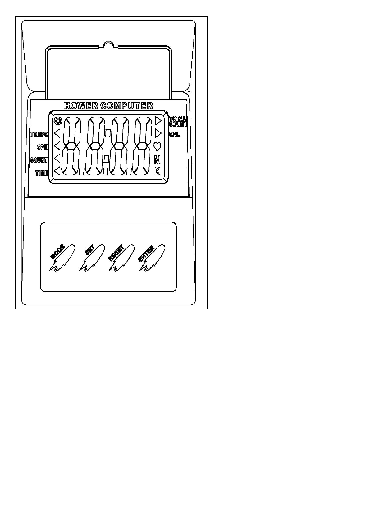
Computer Instructions:
Basic Function:
1. Time: Working range from 0:00-99:59
2. Count: Working Range from 0-9999
3. SPM: 15SPM-3000.
4. Calories: 0-9999
5. Total Count: 0-9999 Note: Computer
must be turned off and restarted to reset
total count.
6. Tempo: Working range from 0-180
beeps per minute.
Instructions for use:
Install the batteries, and the LCD panel will display with an audible buzz.
Mode: Allows access to various settings:
Enter: Press to set values. Numbers will flash. Press “Set” to fix settings.
Set: Press when digits are flashing to set values upward. Can be applied for all settings with the ex-
ception of “Total Count” and “SPM”. Once values are set, press “Enter” to move into the following
mode.
Reset: Press this key to reset values. Note: Total count can only be reset by taking out and rein-
stalling batteries.
Once values are decided, the computer will scroll through the various settings every six seconds.
The settings can be fixed into a set value (SPM for example) by pressing the “Mode” button. Values
such as time will accumulate toward zero and an audible alarm will sound once zero is reached.
Press any key to stop the alarm.
The Computer will enter sleep mode if not used for over 4minutes, 30 seconds.
12
How Often?
Begin with 5 minute training sessions once a day and aim for around 2:30 to 2:45 for 500m
time. Row at a pace that keeps the water circulating continuously between strokes.
Progress a few minutes more each day until you are comfortable with 30-45 minutes training
time 3 or 4 times a week.
This will provide aerobic endurance benefits, muscle toning and sufficient calorie burning to
form part of a weight loss program.
CAUTION
Always consult a doctor before beginning an exercise program.
Stop immediately if you feel faint or dizzy.
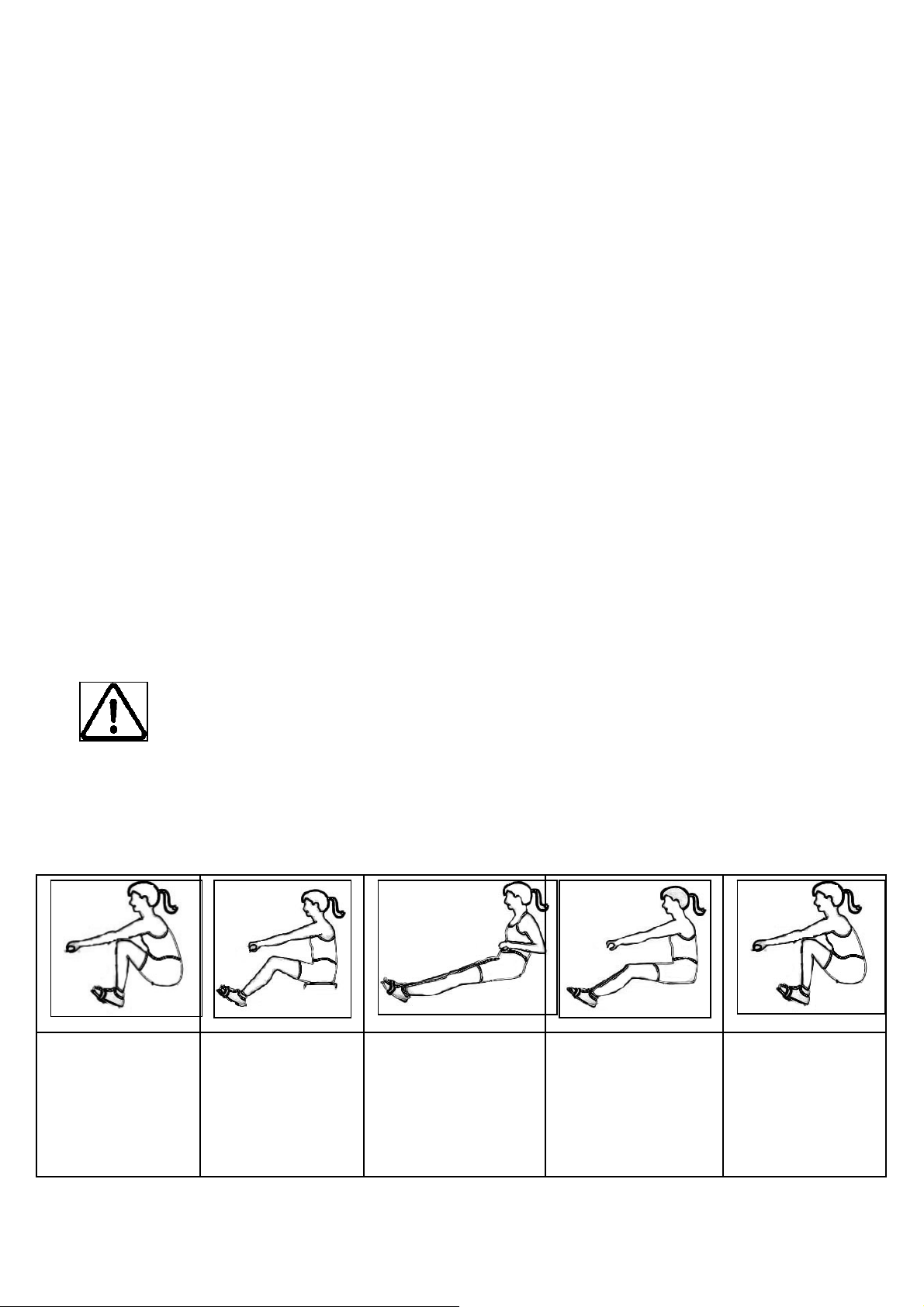
Catch
Comfortably for-
ward with straight
back and arms.
Drive
Push with the
legs while arms
remain straight.
Finish
Pull through with
arms and legs
rocking slightly
back on your pel-
vis.
Recovery
Upper body tips
forward over your
pelvis and move
forward.
Catch
Catch and begin
again.
How to Row?
1. Begin the stroke comfortably forward and push strongly back with your legs while keeping
your arms and back straight.
2. Begin to pull your arms back as they pass over your knees and continue the stroke through
to completion rocking slightly back over your pelvis.
3. Return to the starting position and repeat.
13
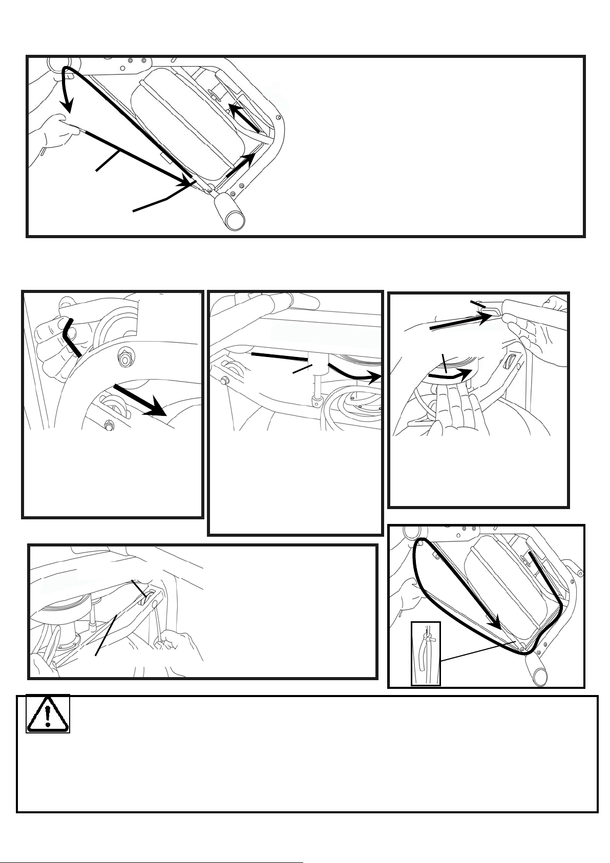
Detaching the Rower Belt:
Reattaching the Rower Belt:
1. Begin reattaching the
Rower Belt by threading
around the Rower Belt Pulley
with the Velcro side facing up-
ward as illustrated.
2. Next, thread the Belt around
the Idle Wheel as shown.
Once around the Idle Wheel,
attach the Rower Belt to the
Belt/Bungee Pulley. There is
an obvious “lip” at the attach-
ment point.
Idle Wheel
Velcro
facing up-
ward
3. Wind the Rower Belt onto the
Belt/Bungee Pulley until the
Rower Handle is as it’s furthest
forward position.
Rower Handle
Belt/Bungee Pulley
Hint:
If Bungee Shock Cords previous tension seemed correct (a good way to judge is if the Rower Handle
can make it to the furthest point forward on the top of the Mainframe under bungee tension alone) then
simply tie off at previous position. If the return is too slack, experiment by tightening the tension in
small increments and testing until the correct tension is achieved. If the Rower Handle cannot reach
the end of the seat rail during a rowing stroke, then the Bungee Shock Cord is over-tensioned.
4. Rethread the Bungee Shock
Cord (on opposite side of the
Idle Wheel) back through the
Bungee Pulleys and tie off at
the Attachment Point.
Bungee Shock Cord
Bungee Pulley
1. To detach belt, simply pull beyond the range of
the normal rowing stroke until the belt detaches
from the Belt Bungee Pulley.
Tip: You’ll hear the Velcro separating just before
the belt detaches.
2. Cut plastic tie holding bungee at the Bungee
Attachment Point, pull the Cord through all three
pulleys and leave excess on top of the tank for
now.
Bungee Shock Cord
Bungee Attachment Point
14
Tip: Correct bungee tension is achieved when enough recoil is present for the Rowing
Handle to easily reach the front of the Rower Pulley Belt Bracket at the far front of the
frame. If the Rowing Handle will not reach rearward to the end of the Seat Rail, the
Bungee Cord is over-tightened and will require adjustment.
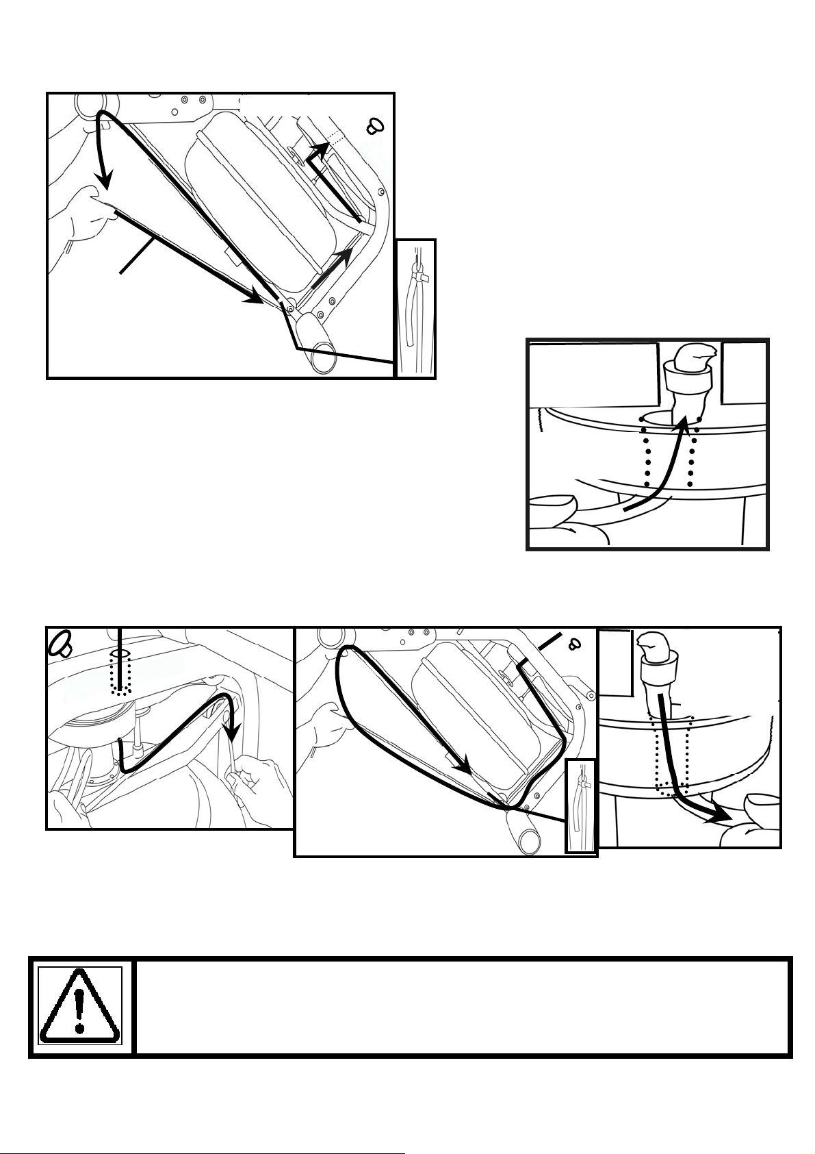
Replacing the Bungee Shock Cord:
Reinstall the Shock Cord through the Upper Frame, along the opposite side of Idle Wheel, through
the Mid Frame and Lower Bungee Pulleys and then tie off with plastic tie wrap to correct tension.
Replace Frame Plug
Bungee
Shock Cord
Bungee Attachment Point
Pull Bungee
through un-
til seated
securely
Removing the Bungee Shock Cord:
First, move the Rowing Handle to it’s farthest
forward point on the Mainframe, then cut the
plastic end tie and follow the drawing above
for bungee removal. Next, remove the Upper
Frame Plug to allow the Bungee Shock Cord
to be threaded through the top of the frame.
Note: You will need to rotate the Belt/Bungee
Pulley to align the holes properly. Should the
belt drop off of during the bungee change,
please refer to the previous pages for
“Attaching/Reattaching the Rower Belt”.
Bungee
Shock Cord
Bungee Attachment Point
Upper Frame Plug
Once Bungee Cord and Upper Frame Hole are aligned, push
the Bungee Cord up and through the frame as shown
Upper Frame
Hole
Belt/ Bungee
Pulley

15
Troubleshooting:
Fault Probable Cause Solution
Water changes color
or becomes cloudy.
Rower is in direct sunlight or
has not had water treatment.
Change rower location to reduce
direct exposure to sunlight. Add
water treatment or change tank
water as directed in the water
treatment section of this manual.
Rower belt slipping
off belt/ bungee pul-
ley.
Bungee not under enough ten-
sion.
Tighten bungee cord following the
instructions given in the change
bungee section of this manual.
Front leg rises slightly
during vigorous row-
ing
M10X180mm Vertical Frame
Tensioning Bolt is slightly too
loose.
Tighten bolt 1/2 turn and try
again. Tighten as needed until
problem stops. Note: Over tight-
ening this bolt can damage the
seat rail. Only tighten bolt until
mid leg begins to lift slightly from
the ground. Refer to “Fine Tun-
ing the Neptune Challenge AR”
for details.
The Neptune Chal-
lenge AR computer
does not illuminate
after battery installa-
tion.
Batteries installed incorrectly or
need replacing.
Reinstall batteries in correct posi-
tion and try again. If the LCD
screen fails to illuminate, replace
batteries. If this fails, contact your
local service center.
Neptune Challenge
AR Computer screen
illuminates, but does
not register when
rowing.
Loose or failed connection.
Check that the computer lead is
connected properly. If it is con-
nected then contact your local
service center.
16
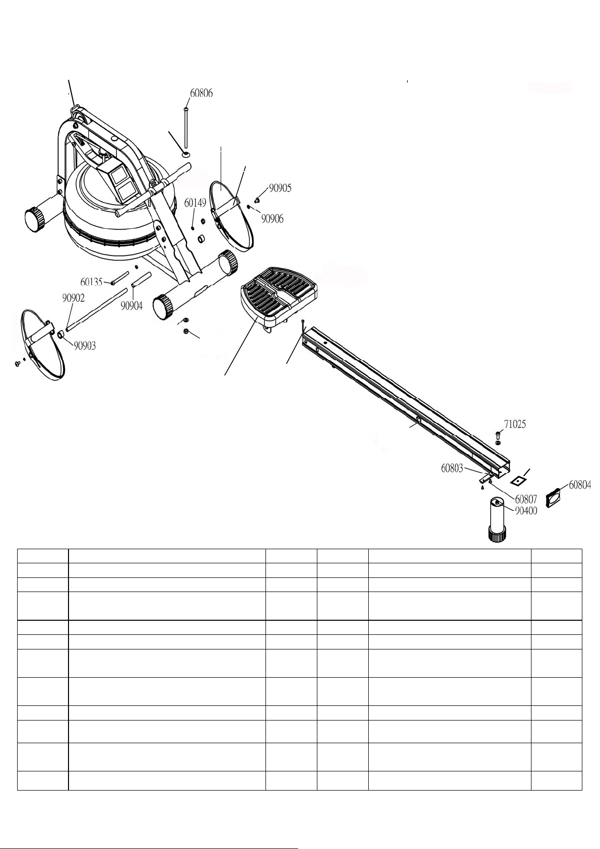
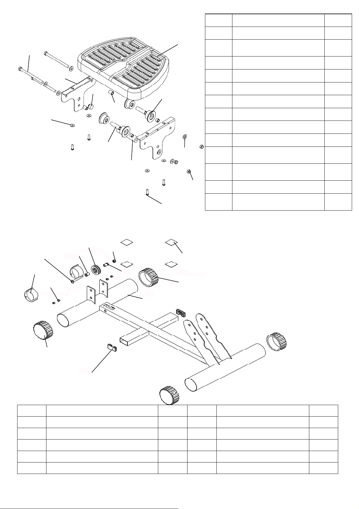
Neptune Challenge AR Rower Exploded Diagram
90801
Refer to Seat
Assembly
10041
10082
90907
90901
90803
Upper and Lower Frame Assembly
91022
60809
P/N Description QTY P/N Description QTY
10041 Nut Nylock M10 2 90801 Rail for Neptune 1
10082 Washer M10 2 90803 Sensor With Lead 1
60135 Bolt M10x95 1 91022
Seat Rail Internal Support
Bracket - NEPAR
1
60149 Spring Washer M10 5x7x2 2 90901 Plastic Footplate 2
60803 Rubber Bump Stop - Seat Rail 1 90902 Footplate Axle 12mmx388 1
60804 Seat Rail End Cap 75x50 1 90903
Footplate Spacer Nylon
D25xD17x19L
2
60806 Frame Tensioning Bolt M10x180 1 90904
Internal Footplate Spacer
17mmx1.5Tx110L
1
60807 Bolt M6x10 2 90905 Footplate Bolt M8x15 2
60809 Plastic Dome Cap 10mm 1 90906 Spring Washer M8x10 2
71025
Main shaft Rear Bracket Bolt
M10x25mm
1 90907 Velcro Foot Strap for Neptune 2
90400 Rear Leg for Neptune 1
17
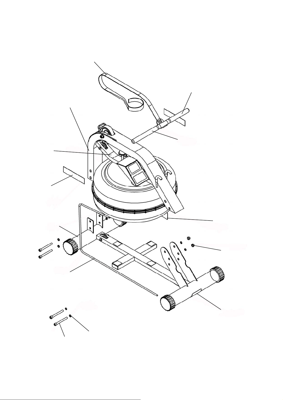
Refer to Upper Main Frame
and Tank Assembly
Refer to Lower Main
Frame Assembly
90812 x2 Decal—
Neptune Challenge
61006 x1 Tank Level
Decal
61007 x1 Main Frame
Lower Warning Decal—
White
10041 x4 Nut
M10 Nylock
60149 x8 Spring Washer
M10 5x7x2
60135 x4 Bolt M10x95
60615 x1 Bungee
Cord 8mmx1950
with Clip 60617 &
Tie 61008
60507 X1 Rowing Belt & Velcro Strip
60501 X1 Rower Handle & Belt
Bracket
60506 X2 Neptune Handle Grip
61004 x 1 Main Frame
Upper Warning Decal—
Orange
18
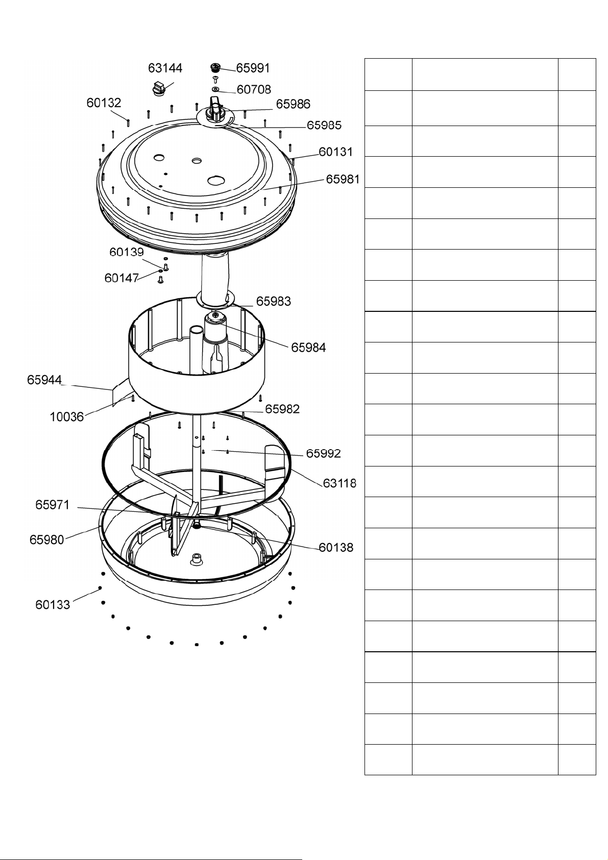
Tank Assembly
P/N Description Qty
10036
Grub Screw M3x20 SUS
for Blue Tank Ring
12
60131
Tank Outer Rubber Pro-
tection Ring
1
60132 Screw M3x20 24
60133 Nut Nylock M3 24
60138 Impeller End Cap 1
60139
Tank Internal Screw S/
Steel M6x15
3
60147
Washer O Ring
9.5x6.5x1.5mm
2
60606
Plastic Spacer M4 for Heel
Adjuster
2
60708 Washer M8.5x19x1.6t 1
63118
Tank Large Ring Seal -
Yellow
1
63144 Tank Plug 1
65944 Decal - Tank Level 1
65971 Impeller - AR 1
65980 Lower Tank Cover 1
65981 Outter Tank - AR 1
65982 Inner Tank - AR 1
65983 adjuster Knob 1
65984 Tank adjuster inner cup 1
65985 Decal - AR Resistance 1
65986 Adjuster Knob 1
65991 End cap-Adjuster Knob 1
65992 Grub Screw M3x12 SUS 4
19
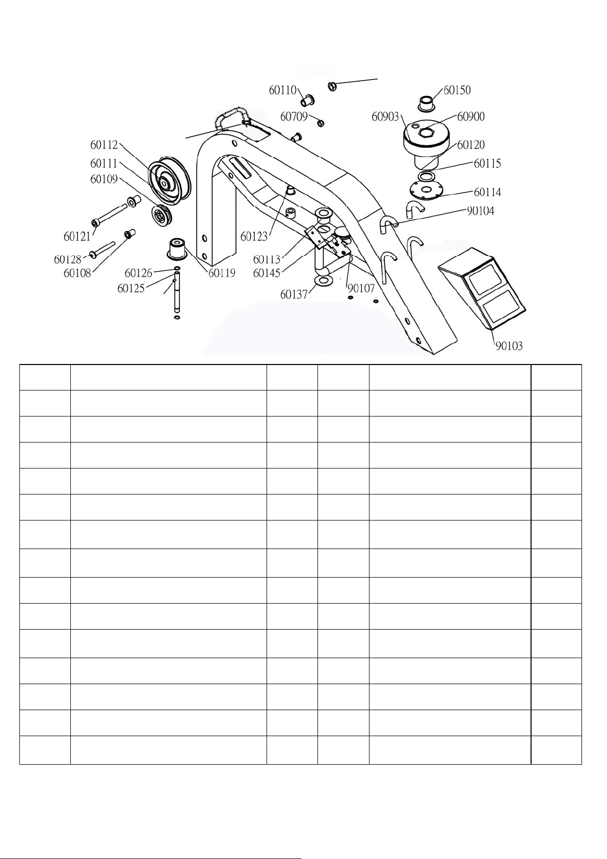
90100
10052
10041
Upper Main Frame
P/N Description QTY P/N Description QTY
10041 Nut M10 Nylock 1 60125 Idler Pulley Shaft 1
10052 Grub Screw M4x6 1 60126 C Clip 10mm 2
60108 Bungee Pulley Spacer 8mm 2 60128 Bolt M8x65 1
60109 Bungee Pulley 50mm 1 60137 Tank/Main Frame Spacer 1
60110 Belt Pulley Spacer 2 60145 Frame Plug 38.1mm 1
60111
Belt Pulley 100mm (inc. 2x60112
Bearing)
1 60150
Main Shaft Nylon Bushing -
Upper
1
60112 Belt pulley bearing 6000ZZ 4 60606
Plastic Spacer M4 for Heel
Adjuster
2
60113 Main Shaft Oil Bushing - Lower 1 60709 Nut Nylock M8 1
60114 Magnet Ring (inc. 6x60124 Magnet) 1 60900 Bungee/ Belt Pulley complete 1
60115 Flywheel Shaft Spacer 1 60903
Velcro Strip for Rower Belt
Pulley
1
60119 Idle wheel inc. 2x60112 Bearing 1 90100 Upper Frame 1
60120 Roll Pin 6mm 1 90103 Computer for Neptune 1
60121 Bolt M10x90 1 90104 Hook 2
60123
Idle Shaft Upper Frame Mount
10mm
1 90107 Computer Plastic Spacer 1
20
Seat Assembly
60209
61001
60211
60109
60108 60128
60212
90200
60709
60108
60209
60210
Lower Main Frame
90708
60706
90709
60710
65121
60707
90701
60702
60708
60709
60711
90707
P/N Description QTY P/N Description QTY
60108 Bungee Pulley Spacer 8mm 2 60211 Transport Wheel 76.2 2
60109 Bungee Pulley 50mm 1
60212 End Cap 25x50mm
2
60128 Bolt M8x65 1
60709 Nut Nylock M8
1
60209 End Cap 76.2mm Round 4 61001
Tank Bonding Strip 3M-VHB
4
60210 Transport Wheel Fastener
4
90200 Lower Frame
1
P/N Description QTY
60702
Seat Wheel
4
60706
Inner Axle Bushing Long
52.5mm
2
60707
Bolt M8x120
3
60708
Washer M8x22
6
60709 Nut Nylock M8 3
60710 Washer M6x11 4
60711 Screw M6x20 4
65121 Seat Frame Bracket
2
90701 Seat - LS-E22
1
90705
Inner Axle Bushing Short for
Neptune
2
90707
Lower Seat Wheel Axle
Spacer 102mm
1
90708 Round Magnet 1
90709
Inner Axle Bushing Long
16mm
2

21
NEPTUNE Challenge AR Rower
INTERNATIONAL WARRANTY – HOME USE
First Degree Fitness Limited warrants that the Neptune Challenge AR (model NEPAR), purchased
from an authorised agent and in its undamaged original packaging, is free from defects in materials
and workmanship. First Degree Fitness Limited or its agent will, at their discretion, repair or replace
parts that become defective within the warranty period, subject to the specific inclusions and exclu-
sions below.
Metal Frame – 5 Year Limited Warranty
First Degree Fitness will repair or replace the metal Main Frame of the Rower should it fail due to any
defect in materials or workmanship within 5 years of the original purchase. Warranty does not apply
to frame coating.
Polycarbonate Tank & Seals – 3 Year Limited Warranty
First Degree Fitness will repair or replace the polycarbonate tank or seals should they fail due to any
defect in materials or workmanship within 3 years of the original purchase.
Mechanical Components (of a non-wearing nature) – 2 Year Limited Warranty
First Degree Fitness will repair or replace any mechanical component should it fail due to any defect
in materials or workmanship within 2 years of the original purchase.
Specific Inclusions
Aluminum Seat Rail
Stainless Steel Impeller Assembly
All Other Components (of a wearing nature) – 1 Year Limited Warranty
First Degree Fitness will repair or replace any component should it fail due to any defect in materials
or workmanship within 1 year of the original purchase.
Specific Inclusions
Bungee recoil cord
Hand grips & foot straps
Polyester rowing belt
Seat
All pulleys, rollers & bearings
All rubber components
Computer & speed sensor (excluding replaceable batteries)
Footplates (pivoting & sliding)
General Exclusions
Damage to the finish of any part of the machine
Damage due to neglect, abuse, incorrect assembly or use of the machine
Any charges for freight or customs clearance associated with the return or dispatch of parts
Any damage to or loss of goods during transport of any kind
Any labour cost associated with a warranty claim
General Conditions
● The serial number of the machine must be correctly registered with First Degree Fitness Limited
or one of its appointed distributors
● First Degree Fitness Limited reserve the right to examine any part where replacement is claimed
under warranty
● Warranty period applies only to the original purchaser from the date of purchase and is not trans-
ferable
● The product must be returned to your place of purchase in original packaging with transportation,
insurance and associated charges paid for by you and risk of loss or damage assumed by you
● First Degree Fitness makes no other warranties except as stated here and expressly disclaims
all warranties not stated in this warranty. Neither First Degree Fitness nor its associates shall be
responsible for incidental or consequential damages
● Manufacturer's warranty automatically commences upon sale of the product to end user or upon
the expiration of one (1) year from month of manufacture, whichever occurs first