Installation/Operation/Maintenance
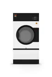
Tumble Dryers
120 Pound (55 Kilogram) Capacity
170 Pound (77 Kilogram) Capacity
200 Pound (90 Kilogram) Capacity
Starting Serial No. 0907003062
Refer to Page 8 for Model Identification
TMB1268C_SVG
Original Instructions
Keep These Instructions for Future Reference.
(If this machine changes ownership, this manual must accompany machine.)
www.alliancelaundry.com
Part No. 70458101ENR11
February 2016

Installation must conform with local codes or, in the absence of local codes, with:
In the U.S.A., installation must conform to the latest edition of the American National Standard Z223.1/ NFPA 54 “National Fuel Gas
Code” and Standard ANSI/NFPA 70 “National Electric Code.”
In Canada, installation must comply with Standards CAN/CSA-B149.1 or Natural Gas and Propane Installation Code and CSA C22.1,
latest edition, Canadian Electric Code, Part I.
In Australia and New Zealand, installation must comply with the Gas Installations Standard AS/NZS 5601 Part 1: General Installa-
tions.
WARNING
FOR YOUR SAFETY, the information in this manual must be followed to minimize the risk of fire or explosion or
to prevent property damage, personal injury or death.
W033
WARNING
• Do not store or use gasoline or other flammable vapors and liquids in the vicinity of this or any other appli-
ance.
• WHAT TO DO IF YOU SMELL GAS:
• Do not try to light any appliance.
• Do not touch any electrical switch; do not use any phone in your building.
• Clear the room, building or area of all occupants.
• Immediately call your gas supplier from a neighbor’s phone. Follow the gas supplier’s instructions.
• If you cannot reach your gas supplier, call the fire department.
• Installation and service must be performed by a qualified installer, service agency or the gas supplier.
W052
IMPORTANT: Information must be obtained from a local gas supplier on instructions to be followed if the user
smells gas. These instructions must be posted in a prominent location. Step-by-step instructions of the above
safety information must be posted in a prominent location near the tumble dryer for customer use.
IMPORTANT: The installer must fully test the tumble dryer after installation and demonstrate to the owner how to
operate the machine.
©
Copyright, Alliance Laundry Systems LLC -
DO NOT COPY or TRANSMIT
3 Part No. 70458101ENR11
WARNING
To reduce the risk of electric shock, fire, explosion, serious injury or death:
• Disconnect electric power to the tumble dryer before servicing.
• Close gas shut-off valve to gas tumble dryer before servicing.
• Close steam valve to steam tumble dryer before servicing.
• Never start the tumble dryer with any guards/panels removed.
• Whenever ground wires are removed during servicing, these ground wires must be reconnected to ensure
that the tumble dryer is properly grounded.
W002R1
WARNING
• Installation of unit must be performed by a qualified installer.
• Install tumble dryer according to manufacturer’s instructions and local codes.
• DO NOT install a tumble dryer with flexible plastic venting materials. If flexible metal (foil type) duct is instal-
led, it must be of a specific type identified by the appliance manufacturer as suitable for use with tumble
dryer. Refer to section on connecting exhaust system. Flexible venting materials are known to collapse, be
easily crushed, and trap lint. These conditions will obstruct tumble dryer airflow and increase the risk of
fire.
W752R1
The following information applies to the state of Massachusetts, USA.
• This appliance can only be installed by a Massachusetts licensed plumber or gas fitter.
• This appliance must be installed with a 36 inch [91 cm] long flexible gas connector.
• A “T-Handle” type gas shut-off valve must be installed in the gas supply line to this appliance.
• This appliance must not be installed in a bedroom or bathroom.
©
Copyright, Alliance Laundry Systems LLC -
DO NOT COPY or TRANSMIT
4 Part No. 70458101ENR11

Table of Contents
Introduction........................................................................................... 8
Model Identification .......................................................................................8
Contact Information...................................................................................... 10
Safety Information................................................................................12
Explanation of Safety Messages..................................................................... 12
Important Safety Instructions......................................................................... 12
Specifications and Dimensions.............................................................. 14
Specifications and Dimensions ...................................................................... 14
120 Series Tumble Dryer Dimensions and Exhaust Outlet Locations .................16
170 and 200 Series Tumble Dryer Dimensions and Exhaust Outlet Locations..... 17
Electric and Gas Connection Locations for Gas Models Through 3/10/13...........18
Electric and Gas Connection Locations for Gas Models Starting 3/11/13............19
Electric and Steam Connection Locations for Steam Models Through 3/10/13....20
Electric and Steam Connection Locations for Steam Models Starting 3/11/13.....21
Electric Connection Location for Electric Models............................................ 23
Installation........................................................................................... 24
Pre-Installation Inspection............................................................................. 24
Location Requirements..................................................................................24
Position and Level the Tumble Dryer..............................................................25
Mounting..................................................................................................... 25
Fire Suppression System (Optional Equipment)............................................... 26
Check Local Codes and Permits..................................................................26
Water Requirements...................................................................................26
Water Connections.....................................................................................26
Electrical Requirements............................................................................. 28
Auxiliary Alarm........................................................................................ 28
Before Placing Tumble Dryer into Service.......................................................28
Required for CE Models Only.................................................................... 30
Installing CE Gas Drying Tumble Dryer..........................................................30
General Information.................................................................................. 30
CE Orifices...............................................................................................31
Properties of CE Gases.............................................................................. 33
Changing Gas Configuration...................................................................... 33
Specific Conversion Procedures..................................................................34
Exhaust Requirements..........................................................................36
Exhaust Requirements...................................................................................36
©
Copyright 2016, Alliance Laundry Systems LLC
All rights reserved. No part of the contents of this book may be reproduced or transmitted in any form or by any means without the expressed
written consent of the publisher.
©
Copyright, Alliance Laundry Systems LLC -
DO NOT COPY or TRANSMIT
5 Part No. 70458101ENR11

Layout......................................................................................................... 36
Make-Up Air................................................................................................36
Venting........................................................................................................ 36
Alternate Venting for 120 Series Tumble Dryers...........................................37
Individual Venting..................................................................................... 38
Manifold Venting...................................................................................... 39
Gas Requirements.................................................................................42
Gas Requirements.........................................................................................42
Gas Supply Pipe Sizing and Looping.............................................................. 44
Low Pressure Gas Pipe Sizes......................................................................44
High Pressure Gas Pipe Sizes..................................................................... 46
High Altitude Orifice Sizing ......................................................................... 48
Electrical Requirements........................................................................51
Electrical Requirements.................................................................................51
Wiring Diagram............................................................................................51
Grounding Instructions..................................................................................51
For CE Models Only..................................................................................52
Service/Ground Location........................................................................... 52
To Connect Electrical Service To The Tumble Dryer........................................ 54
Jumper Configuration Instructions..................................................................54
Ferrite Ring Installation ................................................................................54
Electrical Specifications ............................................................................... 57
Steam Requirements.............................................................................59
Steam Requirements......................................................................................59
Piping Recommendations.............................................................................. 63
Installing Steam Trap and Making Condensate Return Connections...................63
Thermal Oil Prep.......................................................................................... 63
Operating Instructions..........................................................................64
Operating Instructions................................................................................... 64
Emergency Stop Button On CE Models.......................................................... 64
Operating Instructions................................................................................... 64
Reversing Operation......................................................................................65
Control Instructions.......................................................................................65
Dual Digital Timer Control.........................................................................65
Electronic OPL Micro Control....................................................................67
LED OPL Control .................................................................................... 68
UniLinc Control ....................................................................................... 69
DX4 OPL Control..................................................................................... 70
Diagnostic Microprocessor Control ............................................................ 71
DMP OPL Models.....................................................................................71
Ignition Control Operation and Troubleshooting for Models Starting 3/11/13..... 73
Internal Control Failure..............................................................................74
Troubleshooting........................................................................................ 74
Proper Electrode Location..........................................................................75
Flame Current Measurement.......................................................................75
©
Copyright, Alliance Laundry Systems LLC -
DO NOT COPY or TRANSMIT
6 Part No. 70458101ENR11

Ignition Control Operation for Non-CE Models Through 3/10/13...................... 75
Ignition Control Operation for CE Models Through 3/10/13............................. 75
System Tests............................................................................................. 76
Diagnostic LED (DGN LED)/Error Codes...................................................76
Adjustments......................................................................................... 78
Adjustments................................................................................................. 78
Gas Burner Air Shutter.................................................................................. 78
Airflow Switch ............................................................................................ 79
Loading Door Switch.................................................................................... 79
Loading Door Catch (120 and 170 Series Models)........................................... 79
Loading Door Strike (200 Series Models)........................................................80
Belt Drive ................................................................................................... 80
Maintenance......................................................................................... 82
Daily........................................................................................................... 82
Monthly....................................................................................................... 82
Quarterly......................................................................................................82
Bi-Annually................................................................................................. 83
Annually...................................................................................................... 83
Fire Suppression System (Optional Equipment) Maintenance Test.....................83
Before You Call for Service................................................................... 85
Removing Tumble Dryer from Service.................................................. 86
Disposal of Unit.................................................................................... 87
©
Copyright, Alliance Laundry Systems LLC -
DO NOT COPY or TRANSMIT
7 Part No. 70458101ENR11
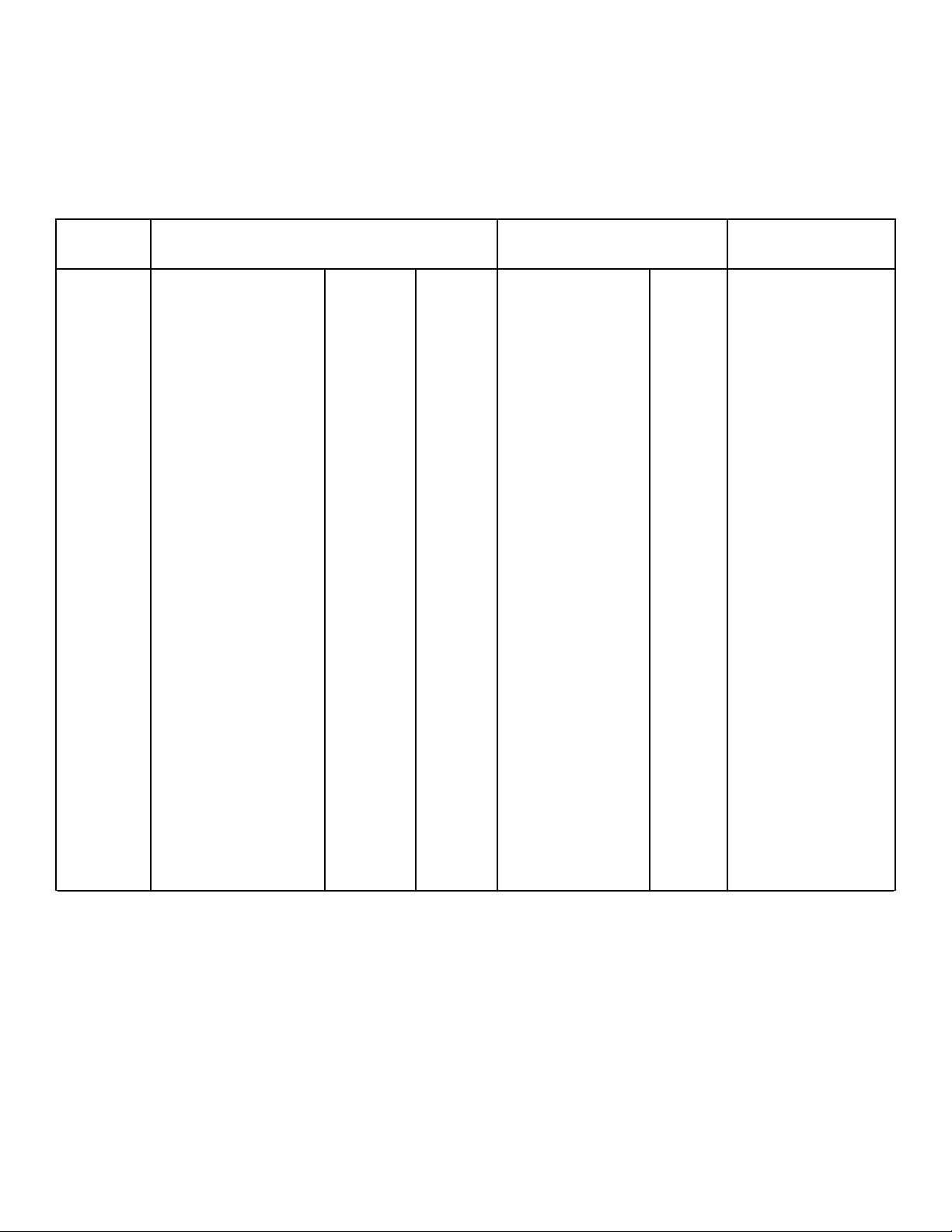
Introduction
Model Identification
Information in this manual is applicable to these models. Refer
to the machine serial plate for the model number.
Gas Steam/Thermal Oil Electric
120 Series
(55 Kg)
CA120L
CA120N
CK120N
CT120L
CT120N
CU120L
CU120N
DR120G2-BA120L
DR120G2-BA120N
DR120G2-BK120N
DR120G2-BT120L
DR120G2-BT120N
DR120G2-BU120L
DR120G2-BU120N
HA120L
HA120N
HK120N
HT120L
HT120N
HU120L
HU120N
IPD120G2
IT120L
IT120N
LA120L
LA120N
LK120N
LT120L
LT120N
LU120L
LU120N
NT120L
NT120N
NU120L
NU120N
PA120L
PA120N
PK120N
PT120L
PT120N
PU120L
PU120N
SA120L
SA120N
SK120N
ST120L
ST120N
SU120L
SU120N
UA120L
UA120N
UK120N
UT120L
UT120N
UU120L
UU120N
XT120L
XT120N
XU120L
XU120N
YT120L
YT120N
YU120L
YU120N
CT120S
CT120T
CU120S
CU120T
DR120S2-BT120S
DR120S2-BT120T
DR120S2-BU120S
DR120S2-BU120T
HT120S
HT120T
HU120S
HU120T
IPD120S2
IT120S
IT120T
LT120S
LT120T
LU120S
LU120T
NT120S
NU120S
PT120S
PT120T
PU120S
PU120T
ST120S
ST120T
SU120S
SU120T
UT120S
UT120T
UU120S
UU120T
XT120S
XT120T
XU120S
XU120T
YT120S
YT120T
YU120S
YU120T
CT120E
CU120E
DR120E2-BT120E
DR120E2-BU120E
HT120E
HU120E
IT120E
LT120E
LU120E
NT120E
NU120E
PT120E
PU120E
ST120E
SU120E
UT120E
UU120E
YT120E
YU120E
Table continues...
Introduction
©
Copyright, Alliance Laundry Systems LLC -
DO NOT COPY or TRANSMIT
8 Part No. 70458101ENR11
Gas Steam/Thermal Oil Electric
170 Series
(77 Kg)
CA170L
CA170N
CK170N
CT170L
CT170N
CU170L
CU170N
DR170G2-BA170L
DR170G2-BA170N
DR170G2-BK170N
DR170G2-BT170L
DR170G2-BT170N
DR170G2-BU170L
DR170G2-BU170N
HA170L
HA170N
HK170N
HT170L
HT170N
HU170L
HU170N
IPD170G2
IT170L
IT170N
LA170L
LA170N
LK170N
LT170L
LT170N
LU170L
LU170N
NT170L
NT170N
NU170L
NU170N
PA170L
PA170N
PK170N
PT170L
PT170N
PU170L
PU170N
SA170L
SA170N
SK170N
ST170L
ST170N
SU170L
SU170N
UA170L
UA170N
UK170N
UT170L
UT170N
UU170L
UU170N
XT170L
XT170N
XU170L
XU170N
YT170L
YT170N
YU170L
YU170N
CT170S
CT170T
CU170S
CU170T
DR170S2-BT170S
DR170S2-BT170T
DR170S2-BU170S
DR170S2-BU170T
HT170S
HT170T
HU170S
HU170T
IPD170S2
IT170S
IT170T
LT170S
LT170T
LU170S
LU170T
NT170S
NU170S
PT170S
PT170T
PU170S
PU170T
ST170S
ST170T
SU170S
SU170T
UT170S
UT170T
UU170S
UU170T
XT170S
XT170T
XU170S
XU170T
YT170S
YT170T
YU170S
YU170T
Not Applicable
Table continues...
Introduction
©
Copyright, Alliance Laundry Systems LLC -
DO NOT COPY or TRANSMIT
9 Part No. 70458101ENR11
Gas Steam/Thermal Oil Electric
200 Series
(90 Kg)
CA200L
CA200N
CT200L
CT200N
CU200L
CU200N
DR200G2-BA200L
DR200G2-BA200N
DR200G2-BT200L
DR200G2-BT200N
DR200G2-BU200L
DR200G2-BU200N
HA200L
HA200N
HT200L
HT200N
HU200L
HU200N
IT200L
IT200N
LA200L
LA200N
LT200L
LT200N
LU200L
LU200N
NT200L
NT200N
NU200L
NU200N
PA200L
PA200N
PT200L
PT200N
PU200L
PU200N
SA200L
SA200N
ST200L
ST200N
SU200L
SU200N
UA200L
UA200N
UT200L
UT200N
UU200L
UU200N
CT200S
CT200T
CU200S
CU200T
DR200S2-BT200S
DR200S2-BT200T
DR200S2-BU200S
DR200S2-BU200T
HT200S
HT200T
HU200S
HU200T
IT200S
IT200T
LT200S
LT200T
LU200S
LU200T
NT200S
NU200S
PT200S
PT200T
PU200S
PU200T
ST200S
ST200T
SU200S
SU200T
UT200S
UT200T
UU200S
UU200T
Not Applicable
Explanation of digit in 6th position of model number:
E = Electric
L = Liquid Petroleum (L.P.) Gas
N = Natural Gas
S = Steam
T = Thermal Oil
Includes models with the following control suffixes
R3 – reversing DX4 OPL RE – reversing LED OPL RQ – reversing dual digital timer
RD – reversing DMP OPL RM – reversing OPL micro RU – reversing UniLinc OPL
Contact Information
If service is required, contact the nearest Factory Authorized
Service Center.
If you are unable to locate an authorized service center or are un-
satisfied with the service performed on your unit, contact:
Alliance Laundry Systems
Shepard Street
P.O. Box 990
Ripon, WI 54971-0990
U.S.A.
www.alliancelaundry.com
Phone: +1 (920) 748-3121 Ripon, Wisconsin
+32 56 41 20 54 Wevelgem, Belgium
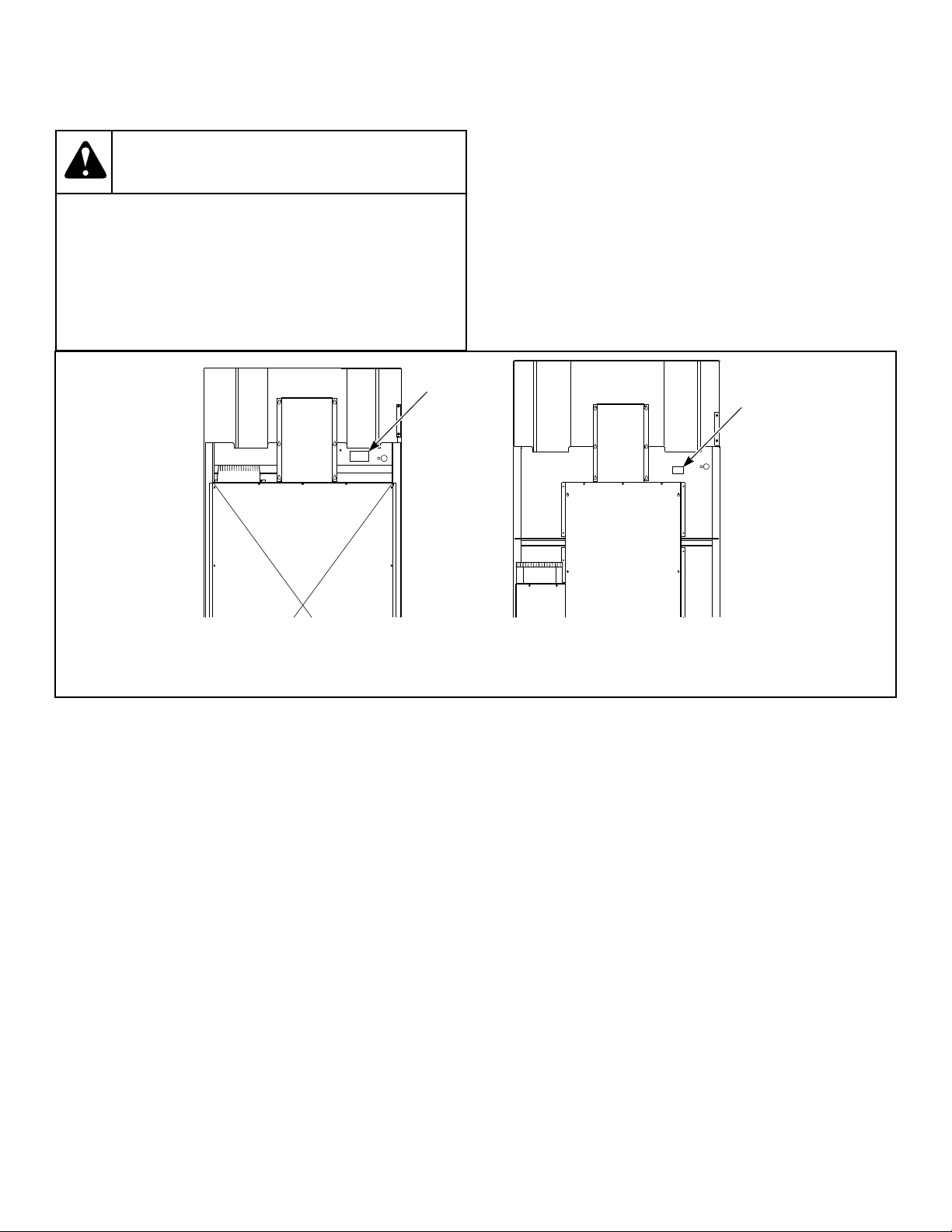
When calling or writing about your unit, PLEASE GIVE THE
MODEL AND SERIAL NUMBERS. The model and serial num-
bers are located on the serial plate. The serial plate will be in the
location shown in Figure 1 .
Date Purchased ______________________________
Model Number ______________________________
Serial Number _______________________________
Introduction
©
Copyright, Alliance Laundry Systems LLC -
DO NOT COPY or TRANSMIT
10 Part No. 70458101ENR11
Please include a copy of your bill of sale and any service receipts
you have.
WARNING
To reduce the risk of serious injury or death, DO NOT
repair or replace any part of the unit or attempt any
servicing unless specifically recommended in the
user-maintenance instructions or in published user-
repair instructions that you understand and have the
skills to carry out.
W329
If replacement parts are required, contact the source from where
you purchased your unit or call +1 (920) 748-3950 or +32 56 41
20 54 for the name and address of the nearest authorized parts
distributor.
TMB2288N_SVG
1
120 170/200
1
1. Serial Plate
Figure 1
Introduction
©
Copyright, Alliance Laundry Systems LLC -
DO NOT COPY or TRANSMIT
11 Part No. 70458101ENR11
Safety Information
Explanation of Safety Messages
Precautionary statements (“DANGER,” “WARNING,” and
“CAUTION”), followed by specific instructions, are found in this
manual and on machine decals. These precautions are intended
for the personal safety of the operator, user, servicer, and those
maintaining the machine.
DANGER
Indicates an imminently hazardous situation that, if
not avoided, will cause severe personal injury or
death.
WARNING
Indicates a hazardous situation that, if not avoided,
could cause severe personal injury or death.
CAUTION
Indicates a hazardous situation that, if not avoided,
may cause minor or moderate personal injury or
property damage.
Additional precautionary statements (“IMPORTANT” and
“NOTE”) are followed by specific instructions.
IMPORTANT: The word “IMPORTANT” is used to in-
form the reader of specific procedures where minor
machine damage will occur if the procedure is not fol-
lowed.
NOTE: The word “NOTE” is used to communicate in-
stallation, operation, maintenance or servicing informa-
tion that is important but not hazard related.
Important Safety Instructions
WARNING
To reduce the risk of fire, electric shock, serious in-
jury or death to persons when using your tumbler,
follow these basic precautions.
W776
Save These Instructions
• Read all instructions before using the tumble dryer.
• Install the tumble dryer according to the INSTALLATION in-
structions. Refer to the EARTHING (grounding) instructions
for the proper earthing (grounding) of the tumble dryer. All
connections for electrical power, earthing (grounding) and gas
supply must comply with local codes and be made by licensed
personnel when required. It is recommended that the machine
be installed by qualified technicians.
• Do not install or store the tumble dryer where it will be ex-
posed to water and/or weather. The tumble dryer cannot be
used in a closed room where the air supply is insufficient. If
necessary, ventilation grids must be installed in the doors or
the windows.
• This appliance must not be activated without lint/foam filter.
• When you perceive a gas odor, immediately switch off the gas
supply and ventilate the room. Do not switch on electrical ap-
pliances and do not pull electrical switches. Do not use
matches or lighters. Do not use a phone in the building. Warn
the fitter, and if so desired, the gas company, as soon as possi-
ble.
• To avoid fire and explosion, keep surrounding areas free of
flammable and combustible products. Regularly clean the
dryer drum and exhaust tube should be cleaned periodically
by competent maintenance personnel. Daily remove piled up
dust from filter and inside of filter compartment.
• Do not use or store flammable materials near this appliance.
• Do not dry articles that have been previously cleaned in,
washed in, soaked in or spotted with gasoline or machine oils,
vegetable or cooking oils, cleaning waxes or chemicals, dry-
cleaning solvents, thinner or other flammable or explosive
substances as they give off vapors that could ignite, explode
or cause fabric to catch on fire by itself.
• Do not spray aerosols in the vicinity of this appliance while it
is in operation.
• Items such as foam rubber (latex foam), shower caps, water-
proof textiles, rubber backed articles and clothes or pillows
filled with foam rubber pads should not be dried in the tumble
dryer. Do not use the appliance to dry materials with a low
melting temperature (PVC, rubber, etc.).
• Do not tumble fiberglass curtains and draperies unless the la-
bel says it can be done. If they are dried, wipe out the cylinder
with a damp cloth to remove particles of fiberglass.
• Do not allow children on or in the tumble dryer. This appli-
ance is not intended for use by young children or infirm per-
sons without supervision. Young children should be super-
vised to ensure that they do not play with the appliance.
• Do not reach into the tumble dryer if the cylinder is revolving.
• Use tumble dryer only for its intended purpose, drying fab-
rics. Always follow the fabric care instructions supplied by
the textile manufacturer and only use the dryer drum to dry
Safety Information
©
Copyright, Alliance Laundry Systems LLC -
DO NOT COPY or TRANSMIT
12 Part No. 70458101ENR11

textiles that have been washed in water. Only insert spin-dried
linen in the dryer.
• Always read and follow manufacturer’s instructions on pack-
ages of laundry and cleaning aids. Heed all warnings or pre-
cautions. To reduce the risk of poisoning or chemical burns,
keep them out of the reach of children at all times (preferably
in a locked cabinet).
• Do not use fabric softeners or products to eliminate static un-
less recommended by the manufacturer of the fabric softener
or product.
• Remove laundry immediately after tumble dryer stops.
• DO NOT operate the tumble dryer if it is smoking, grinding
or has missing or broken parts or removed guards or panels.
DO NOT tamper with the controls or bypass any safety devi-
ces.
• Tumble dryer will not operate with the loading door open. DO
NOT bypass the door safety switch to permit the tumble dryer
to operate with the door open. The tumble dryer will stop
tumbling when the door is opened. Do not use the tumble dry-
er if it does not stop tumbling when the door is opened or
starts tumbling without pressing or turning the START mech-
anism. Remove the tumble dryer from use and call for serv-
ice.
• Tumble dryer(s) will not operate with lint panel open. DO
NOT bypass lint panel safety switch to permit the tumble dry-
er to operate with the lint panel open.
• Do not modify this appliance.
• Always clean the lint filter daily. Keep area around the ex-
haust opening and adjacent surrounding area free from the ac-
cumulation of lint, dust and dirt. The interior of the tumble
dryer and the exhaust duct should be cleaned periodically by
qualified service personnel.
• Solvent vapors from dry-cleaning machines create acids when
drawn through the heater of the drying unit. These acids are
corrosive to the tumble dryer as well as the laundry load being
dried. Be sure make-up air is free of solvent vapors.
• At the end of each working day, close off all main supplies of
gas, steam and current.
• Do not repair or replace any part of the tumble dryer, or at-
tempt any servicing unless specifically recommended in the
user-maintenance instructions or in published user-repair in-
structions that the user understands and has the skills to carry
out. ALWAYS disconnect and lockout the electrical power to
the tumble dryer before servicing. Disconnect power by shut-
ting off appropriate breaker or fuse.
• Before the tumble dryer is removed from service or discarded,
remove the door to the drying compartment and the door to
the lint compartment.
• Failure to install, maintain, and/or operate this tumble dryer
according to the manufacturer’s instructions may result in
conditions which can produce bodily injury and/or property
damage.
NOTE: The WARNINGS and IMPORTANT SAFETY IN-
STRUCTIONS appearing in this manual are not meant
to cover all possible conditions and situations that may
occur. Common sense, caution and care must be exer-
cised when installing, maintaining, or operating the
tumble dryer.
Always contact your dealer, distributor, service agent or the man-
ufacturer on any problems or conditions you do not understand.
Safety Information
©
Copyright, Alliance Laundry Systems LLC -
DO NOT COPY or TRANSMIT
13 Part No. 70458101ENR11
Specifications and Dimensions
Specifications and Dimensions
Refer to machine serial plate for additional specifications.
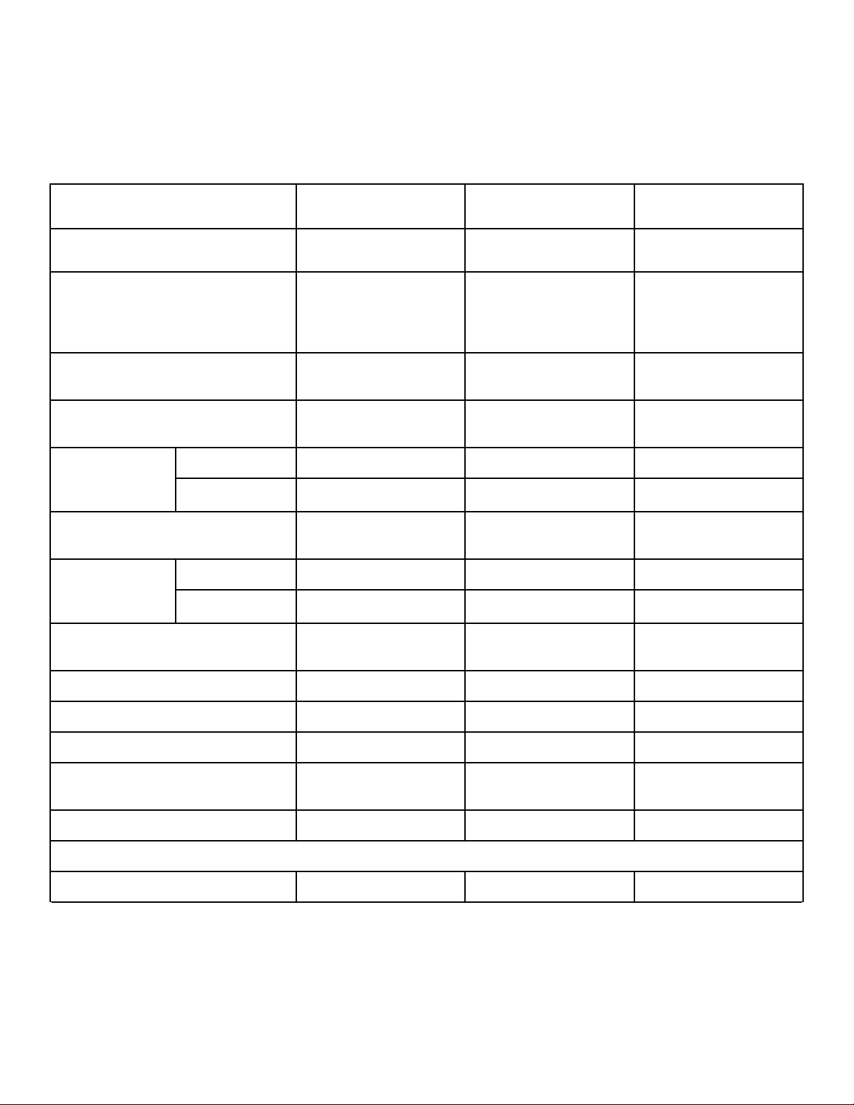
Specifications 120 Series 170 Series 200 Series
Heat dissipation of surface area exposed
to conditioned air: Btu/ft
2
[Joules/m
2
]
60 [681,392] 60 [681,392] 60 [681,392]
Noise level measured during operation
at operator position of 3.3 feet (1 meter)
in front of machine and 5.2 feet (1.6 me-
ters) from floor.
66 dBA 66 dBA 66 dBA
Cylinder Size: Inches [mm] 44 x 41 [1,118 x 1,041] 50.75 x 42.5 [1,289 x
1,080]
50.75 x 50 [1,289 x 1,270]
Cylinder Capacity dry weight: Pounds
[kg]
120 [55] 170 [77] 200 [90]
Standard Packag-
ing Weight:
Pounds [kg]
Gas and Electric 1,338 [607] 1,667 [756] 1,818 [825]
Steam 1,446 [656] 1,776 [806] 1,885 [855]
Standard Packaging Shipping Dimen-
sions: Inch [mm]
48.5 x 71.5 x 90 [1,232 x
1,816 x 2,286]
55.63 x 73.75 x 99 [1,413
x 1,873 x 2,515]
55.63 x 81.25 x 99 [1,413
x 2,064 x 2,515]
Slat Crate Packag-
ing Weight:
Pounds [kg]
Gas and Electric 1,447 [656] 1,791 [812] 1,931 [876]
Steam 1,547 [702] 1,891 [858] 1,998 [906]
Slat Crate Shipping Dimensions: Inch
[mm]
53 x 74.5 x 90.75 [1,346 x
1,892 x 2,305]
60.13 x 76.75 x 99.75
[1,527 x 1,949 x 2,534]
60.13 x 84.25 x 101 [1,527
x 2,140 x 2,565]
Cylinder Motor: HP [kW] 0.75 [0.560] 0.75 [0.560] 0.75 [0.560]
Fan Motor: HP [kW] 1 [0.746] 3 [2.238] 3 [2.238]
Air Outlet Diameter: Inches [mm] 10 [254] 12 [300] 12 [300]
Maximum Static Back Pressure: W.C.I.
[mbar, kPa]
0.8 [2.0, 0.2] 0.8 [2.0, 0.2] 0.8 [2.0, 0.2]
Maximum Airflow: C.F.M. [L/sec.] 1,600 [755] 2,450 [1,156] 2,450 [1,156]
Gas Models
Net Weight (approximate): Pounds [kg] 1,275 [578] 1,575 [716] 1,741 [790]
Table continues...
Specifications and Dimensions
©
Copyright, Alliance Laundry Systems LLC -
DO NOT COPY or TRANSMIT
14 Part No. 70458101ENR11
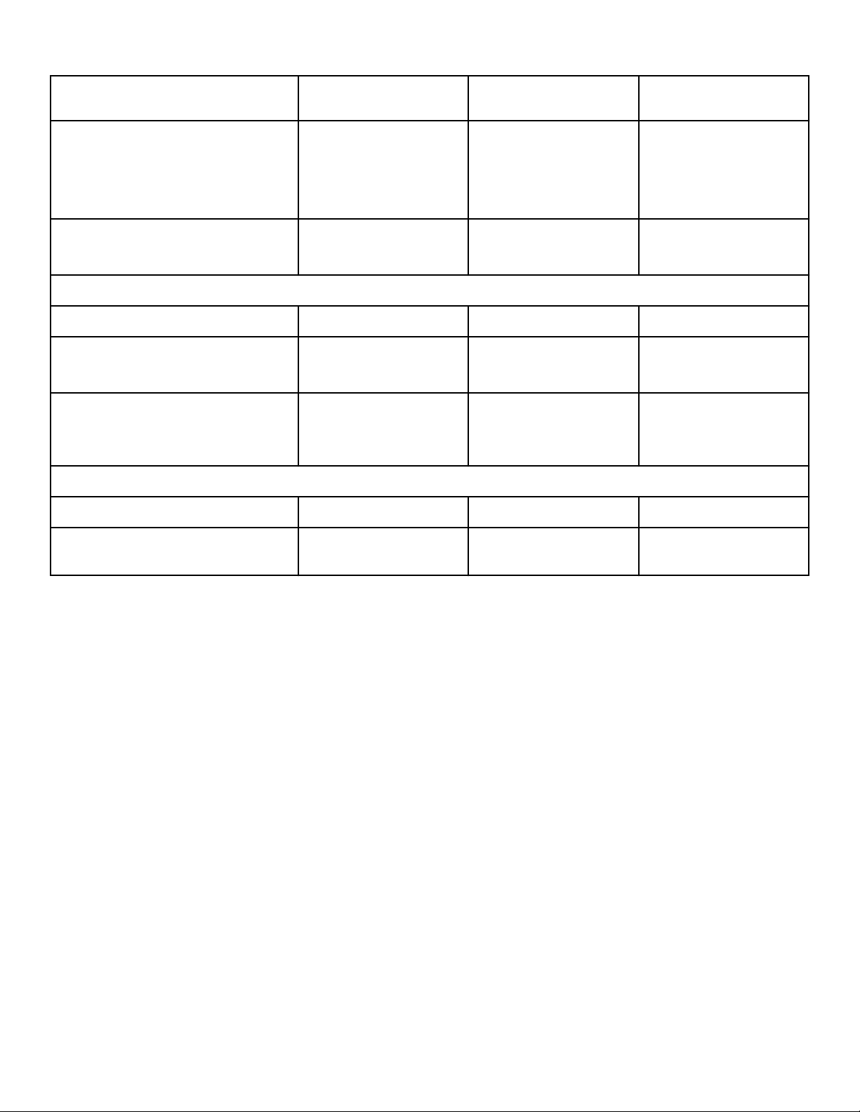
Specifications 120 Series 170 Series 200 Series
Gas Connection Models through 3/10/13:
3/4 in. NPT
Models Starting 3/11/13: 1
in. NPT
1 in. NPT 1 in. NPT
Gas Burner Rating:
Btu/hr. [Mj/hr., kW]
270,000 [285, 79.13] 395,000 [417, 115.77] 425,000 [448, 124.56]
Steam Models
Net Weight (approximate): Pounds [kg] 1,375 [624] 1,675 [761] 1,808 [820]
Steam Connection 3/4 in. NPT inlet
3/4 in. NPT outlet
3/4 in. NPT inlet
1 in. NPT outlet
3/4 in. NPT inlet
1 in. NPT outlet
Steam Coil Rating at 100 psig:
Btu/hr. [kg/hr.] (recommended operating
pressure 80-100 psig)
405,000 [183.1] 648,000 [294.2] 648,000 [294.2]
Electric Models
Net Weight (approximate): Pounds [kg] 1,275 [578] Not Applicable Not Applicable
Heating Element Rating: Kilowatts
(kW)
60 kW Not Applicable Not Applicable
NOTE: All machines are shipped with extra nipple to
convert to metric thread (from Standard).
Specifications and Dimensions
©
Copyright, Alliance Laundry Systems LLC -
DO NOT COPY or TRANSMIT
15 Part No. 70458101ENR11
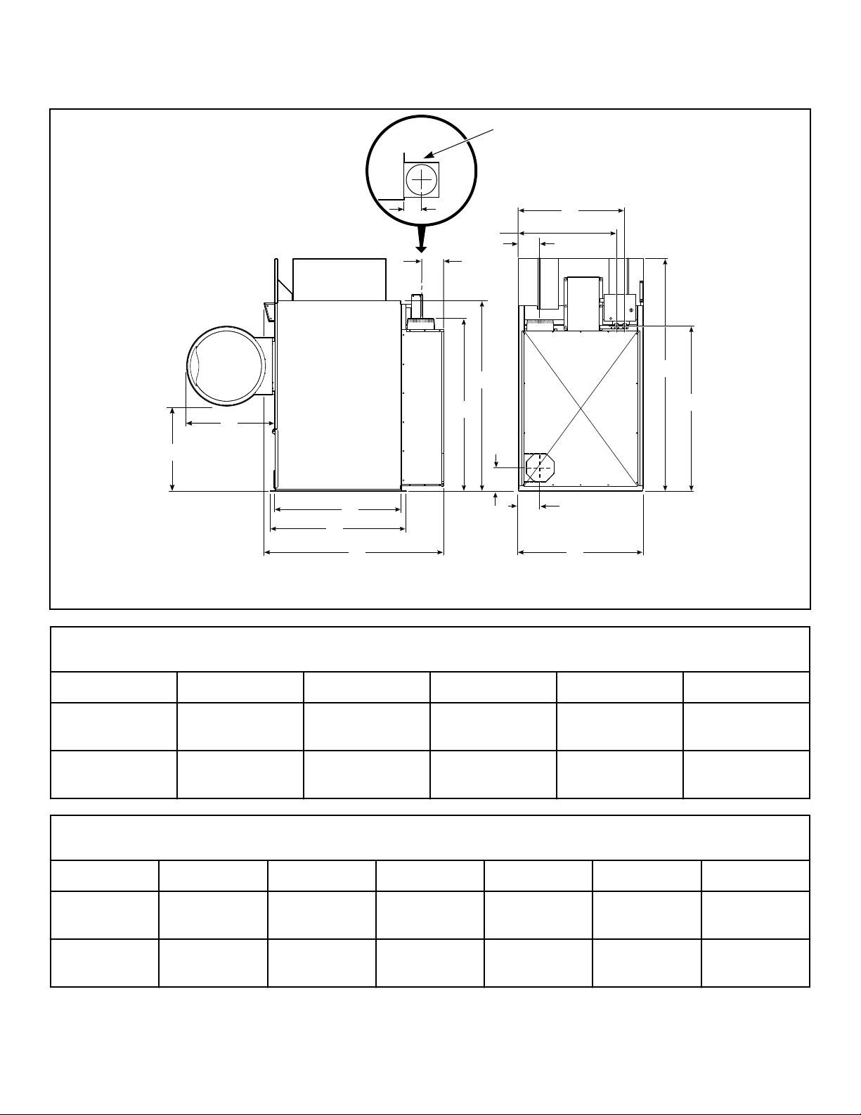
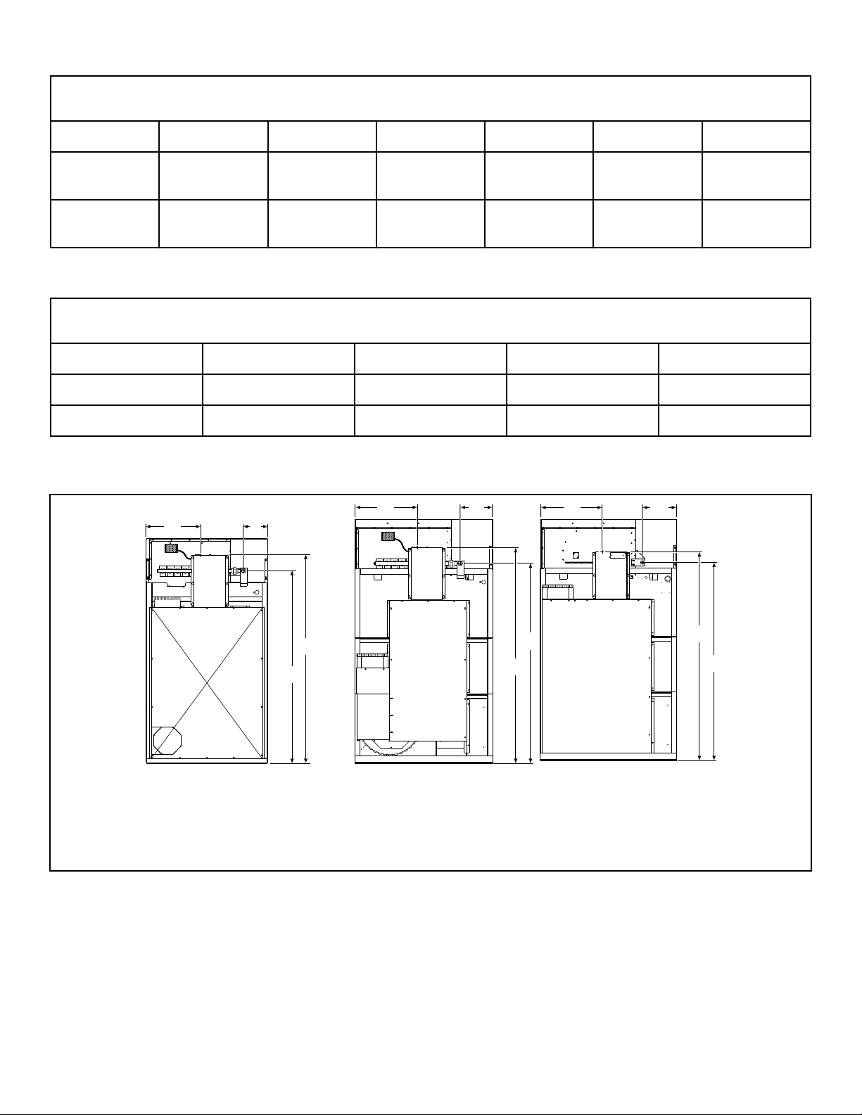
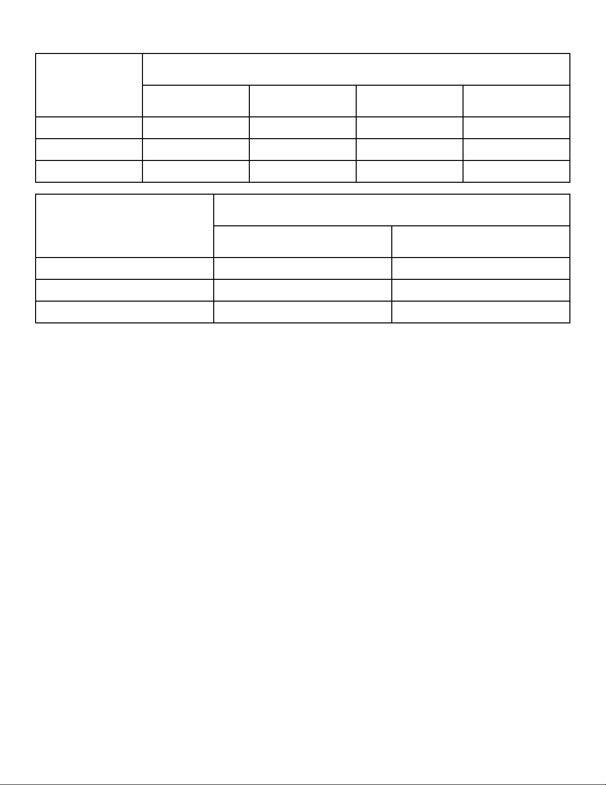
120 Series Tumble Dryer Dimensions and Exhaust Outlet Locations
TMB2423N_SVG
H
U
C
D
E
Y
Z
F
K
G
J
X
I
V
W
B
A
1
1. Top View of Exhaust Duct
Cabinet Dimensions
Models A B C D E
120L/N/E 31.38 in. [797
mm]
32.5 in. [826 mm] 46.5 in. [1,181
mm]
49.91 in. [1,268
mm]
67.92 in. [1,725
mm]
120S 31.38 in. [797
mm]
32.5 in. [826 mm] 46.5 in. [1,181
mm]
49.91 in. [1,268
mm]
67.92 in. [1,725
mm]
Cabinet Dimensions
Models F G H I* J* K*
120L/N/E 46.38 in. [1,178
mm]
85.7 in. [2,177
mm]
70 in. [1,778
mm]
41.6 in. [1,057
mm]
43.2 in. [1,097
mm]
61.5 in. [1,562
mm]
120S 46.38 in. [1,178
mm]
85.58 in. [2,174
mm]
70 in. [1,778
mm]
41.6 in. [1,057
mm]
43.2 in. [1,097
mm]
61.5 in. [1,562
mm]
* Fire suppression system optional - may not be on machine. Refer to Position and Level the Tumble Dryer to temporarily re-
duce the heights of these models.
Specifications and Dimensions
©
Copyright, Alliance Laundry Systems LLC -
DO NOT COPY or TRANSMIT
16 Part No. 70458101ENR11
Exhaust Outlet Dimensions and Locations
Models U V W X Y Z
120L/N/E 63.45 in. [1,612
mm]
8.44 in. [214
mm]
10 in. [254
mm]
8.18 in. [208
mm]
6.82 in. [173
mm]
8.18 in. [208
mm]
120S 60.7 in. [1,542
mm]
8.44 in. [214
mm]
10 in. [254
mm]
8.18 in. [208
mm]
6.82 in. [173
mm]
8.18 in. [208
mm]
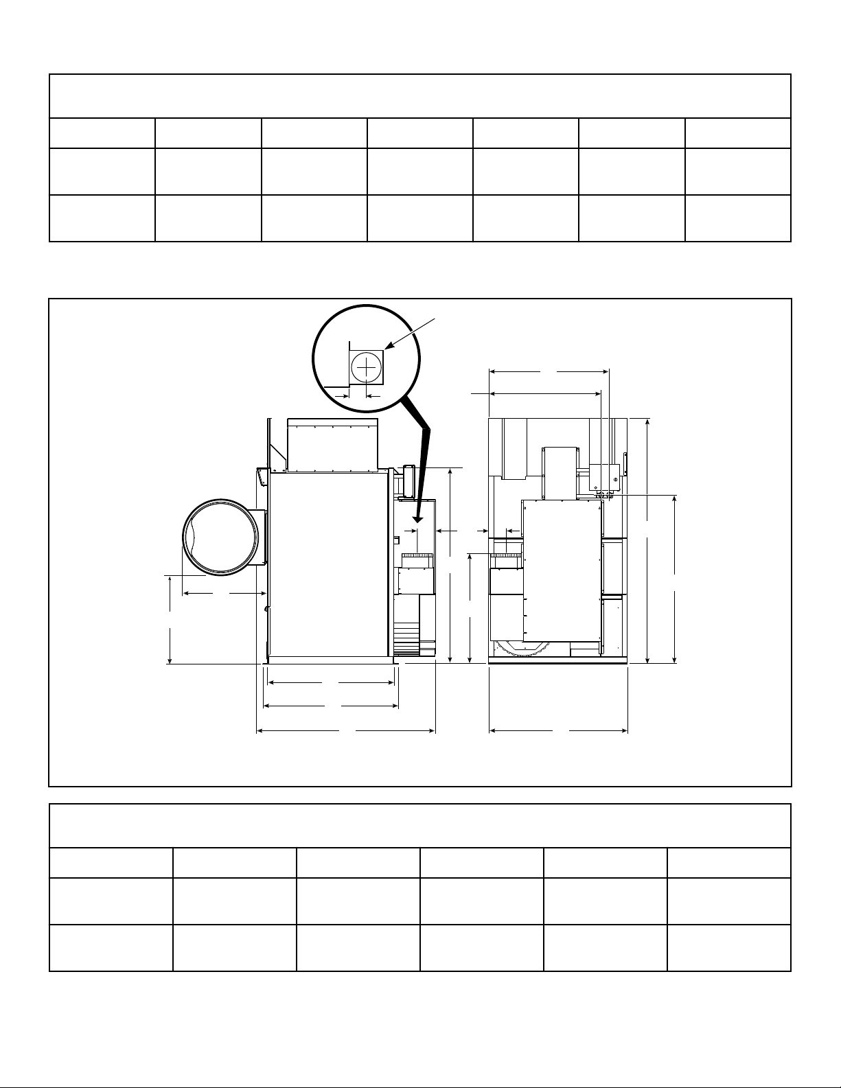
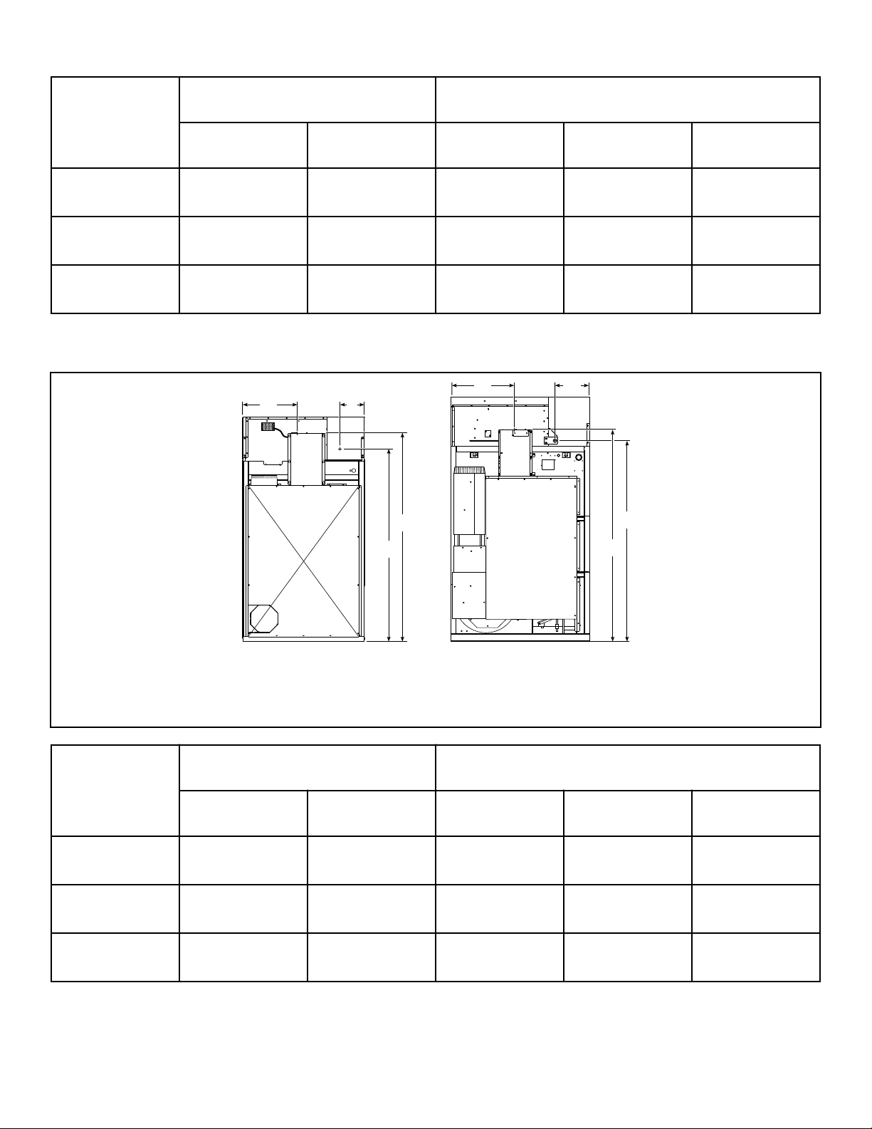
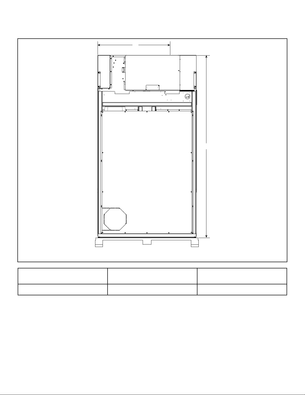
170 and 200 Series Tumble Dryer Dimensions and Exhaust Outlet Locations
TMB2424N_SVG
V
Y
X
W
F
K
G
I
J
E
D
C
H
B
A
1
1. Top View of Exhaust Duct
Cabinet Dimensions
Models A B C D E
170L/N/S 33.86 in. [860
mm]
32.5 in. [ 826 mm] 48.33 in. [1,228
mm]
51.75 in. [1,314
mm]
68.85 in. [1,749
mm]
200L/N/S 32.1 in. [815 mm] 35.6 in. [ 904 mm] 55.83 in. [1,418
mm]
59.25 in. [1,505
mm]
76.35 in. [1,939
mm]
Specifications and Dimensions
©
Copyright, Alliance Laundry Systems LLC -
DO NOT COPY or TRANSMIT
17 Part No. 70458101ENR11
Cabinet Dimensions
Models F G H I* J* K*
170L/N/S 53.12 in. [1,349
mm]
94 in. [2,388
mm]
75.12 in. [1,908
mm]
48.86 in. [1,241
mm]
50.45 in. [1,281
mm]
62.5 in. [1,588
mm]
200L/N/S 53.12 in. [1,349
mm]
94 in. [2,388
mm]
75.12 in. [1,908
mm]
48.86 in. [1,241
mm]
50.45 in. [1,281
mm]
62.5 in. [1,588
mm]
* Fire suppression system optional - may not be on machine. Refer to Position and Level the Tumble Dryer to temporarily re-
duce the heights of these models.
Exhaust Outlet Dimensions and Locations
Models V W X Y
170L/N/S 42.38 in. [1,076 mm] 6.75 in. [171 mm] 12 in. [305 mm] 7 in. [178 mm]
200L/N/S 42.38 in. [1076 mm] 6.75 in. [171 mm] 12 in. [305 mm] 7 in. [178 mm]
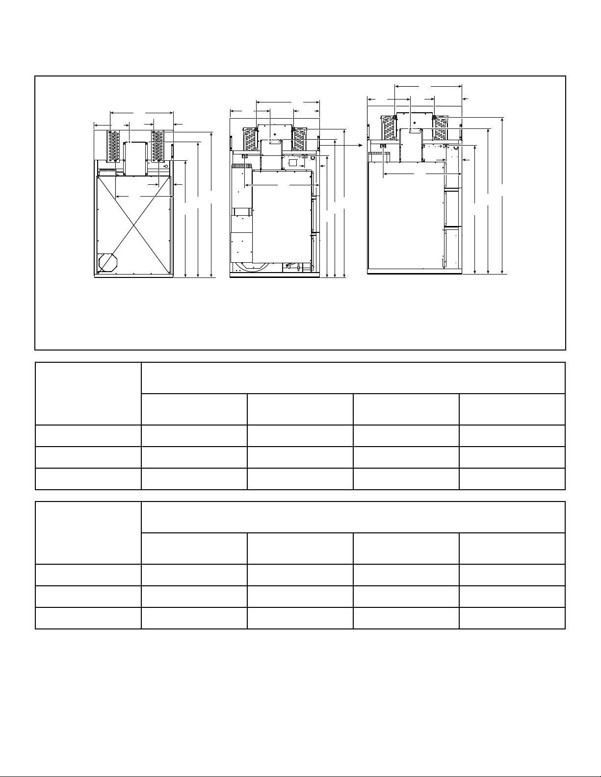
Electric and Gas Connection Locations for Gas Models Through 3/10/13
TMB2255N_SVG
D
B
C
A
B
D
C
A
21
TMB2382N_SVG
A
D
B
C
3
1. 120L/N
2. 170L/N
3. 200L/N
Specifications and Dimensions
©
Copyright, Alliance Laundry Systems LLC -
DO NOT COPY or TRANSMIT
18 Part No. 70458101ENR11
Models
Electrical Connection Gas Connection
A B C D Diameter
120L/N 18.34 in. [466
mm]
77.84 in. [1,977
mm]
12.5 in. [318 mm] 70.5 in. [1,791
mm]
3/4 in. NPT
170L/N 21 in. [533 mm] 81 in. [2,057 mm] 14.85 in. [377
mm]
77.4 in. [1,966
mm]
1 in. NPT
200L/N 21 in. [533 mm] 81 in. [2,057 mm] 13.7 in. [348 mm] 77.4 in. [1,966
mm]
1 in. NPT
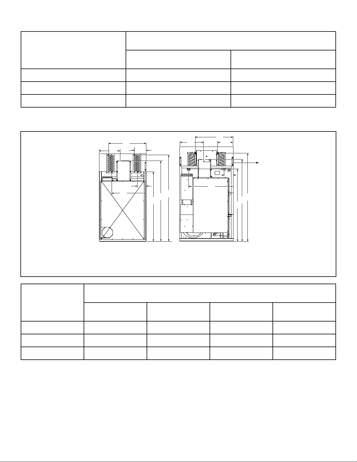
Electric and Gas Connection Locations for Gas Models Starting 3/11/13
TMB2400N_SVG
B
D
D
B
C
C
A
A
21
1. 120L/N
2. 170L/N and 200L/N
Models
Electrical Connection Gas Connection
A B C D Diameter
120L/N 18.34 in. [466
mm]
77.84 in. [1,977
mm]
12.5 in. [318 mm] 70.5 in. [1,791
mm]
1 in. NPT
170L/N 21 in. [533 mm] 81 in. [2,057 mm] 14.85 in. [377
mm]
77.4 in. [1,966
mm]
1 in. NPT
200L/N 21 in. [533 mm] 81 in. [2,057 mm] 14.85 in. [377
mm]
77.4 in. [1,966
mm]
1 in. NPT
Specifications and Dimensions
©
Copyright, Alliance Laundry Systems LLC -
DO NOT COPY or TRANSMIT
19 Part No. 70458101ENR11
Electric and Steam Connection Locations for Steam Models Through 3/10/13
TMB2401N_SVG
B2
B2
B1
B1
D
D
E
E
F
F
A2
A2
A1
A1
C
C
21
TMB2383N_SVG
B2
B1
D
3
E
F
A2
A1
C
1. 120S
2. 170S
3. 200S
Models
Steam Inlet
Diameter A1 A2 F
120S 3/4 in. NPT 35.875 in. [911 mm] 13.375 in. [340 mm] 82.75 in. [2,102 mm]
170S 3/4 in. NPT 37.625 in. [956 mm] 15.25 in. [387 mm] 88 in. [2,235 mm]
200S 3/4 in. NPT 37.625 in. [956 mm] 15.25 in. [387 mm] 88 in. [2,235 mm]
Models
Steam Outlet
Diameter B1 B2 D
120S 3/4 in. NPT 34.625 in. [879 mm] 13.125 in. [333 mm] 68.5 in. [1,740 mm]
170S 1 in. NPT 44.625 in. [1,133 mm] 8.75 in. [222 mm] 71.75 in. [1,822 mm]
200S 1 in. NPT 44.625 in. [1,133 mm] 8.75 in. [222 mm] 71.75 in. [1,822 mm]
Specifications and Dimensions
©
Copyright, Alliance Laundry Systems LLC -
DO NOT COPY or TRANSMIT
20 Part No. 70458101ENR11
Models
Electrical Connection
C E
120S 18.34 in. [466 mm] 77.84 in. [1,977 mm]
170S 21 in. [533 mm] 81 in. [2,057 mm]
200S 21 in. [533 mm] 81 in. [2,057 mm]
Electric and Steam Connection Locations for Steam Models Starting 3/11/13
TMB2401N_SVG
B2
B2
B1
B1
D
D
E
E
F
F
A2
A2
A1
A1
C
C
21
1. 120S
2. 170S and 200S
Models
Steam Inlet
Diameter A1 A2 F
120S 3/4 in. NPT 35.875 in. [911 mm] 13.375 in. [340 mm] 82.75 in. [2,102 mm]
170S 3/4 in. NPT 37.625 in. [956 mm] 15.5 in. [394 mm] 87.625 in. [2,226 mm]
200S 3/4 in. NPT 37.625 in. [956 mm] 15.5 in. [394 mm] 87.625 in. [2,226 mm]
Specifications and Dimensions
©
Copyright, Alliance Laundry Systems LLC -
DO NOT COPY or TRANSMIT
21 Part No. 70458101ENR11
Models
Steam Outlet
Diameter B1 B2 D
120S 3/4 in. NPT 34.625 in. [879 mm] 13.125 in. [333 mm] 68.5 in. [1,740 mm]
170S 1 in. NPT 44.125 in. [1,133 mm] 9 in. [229 mm] 72.125 in. [1,832 mm]
200S 1 in. NPT 44.125 in. [1,133 mm] 9 in. [229 mm] 72.125 in. [1,832 mm]
Models
Electrical Connection
C E
120S 18.34 in. [466 mm] 77.84 in. [1,977 mm]
170S 21 in. [533 mm] 81 in. [2,057 mm]
200S 21 in. [533 mm] 81 in. [2,057 mm]
Specifications and Dimensions
©
Copyright, Alliance Laundry Systems LLC -
DO NOT COPY or TRANSMIT
22 Part No. 70458101ENR11
Electric Connection Location for Electric Models
TMB2336N_SVG
A
B
Models A B
120E 35.81 in. [910 mm] 85.64 in. [2,175 mm]
Specifications and Dimensions
©
Copyright, Alliance Laundry Systems LLC -
DO NOT COPY or TRANSMIT
23 Part No. 70458101ENR11
Installation
Pre-Installation Inspection
Upon delivery, visually inspect the crate, carton and parts for any
visible shipping damage. If the crate, carton, or cover is damaged
or signs of possible damage are evident, have the carrier note the
condition on the shipping papers before the shipping receipt is
signed, or advise the carrier of the condition as soon as it is dis-
covered.
Remove the crate and protective cover as soon as possible and
check the items listed on the packing list. Advise the carrier of
any damaged or missing articles as soon as possible. A written
claim should be filed with the carrier immediately if articles are
damaged or missing.
IMPORTANT: Remove the shipping tape from the two
back draft dampers located in the exhaust outlet.
IMPORTANT: Warranty is void unless tumble dryer is
installed according to instructions in this manual. In-
stallation should comply with minimum specifications
and requirements detailed in this manual and applica-
ble local gas fitting regulations, municipal building co-
des, water supply regulations, electrical wiring regula-
tions, and any other relevant statutory regulations. Due
to varied requirements, applicable local codes should
be thoroughly understood and all pre-installation work
arranged for accordingly.
Materials Required (Obtain Locally)
All Models Circuit breaker on 3 Phase models.
Gas Models One gas shut-off valve for gas service line
to each tumble dryer.
Steam Models One steam shut-off valve for steam service
line to be connected upstream of solenoid
steam valve.
Two steam shut-off valves for each conden-
sate return line.
Flexible steam hoses with a 125 psig
[pounds per square inch gauge] [8.79 kg/sq.
Table continues...
Materials Required (Obtain Locally)
cm] working pressure for connecting steam
coils. Refer to Figure 21 and Figure 22 for
sizing and connection configurations.
Two steam traps for steam coil outlets to
condensate return line.
Optional – Two vacuum breakers for con-
densate return lines.
IMPORTANT: 3 Phase Only – Each tumble dryer must
be connected to its own individual branch circuit
breaker, not fuses, to avoid the possibility of “single
phasing” and causing premature failure of the mo-
tor(s).
Location Requirements
The tumble dryer must be installed on a level floor. Floor cover-
ing materials such as carpeting or tile should be removed.
To assure compliance, consult local building code requirements.
The tumble dryer must not be installed or stored in area where it
will be exposed to water and/or weather.
IMPORTANT: DO NOT block the airflow at the rear of
the tumble dryer with laundry or other articles. Doing
so would prevent adequate air supply to the combus-
tion chamber of the tumble dryer.
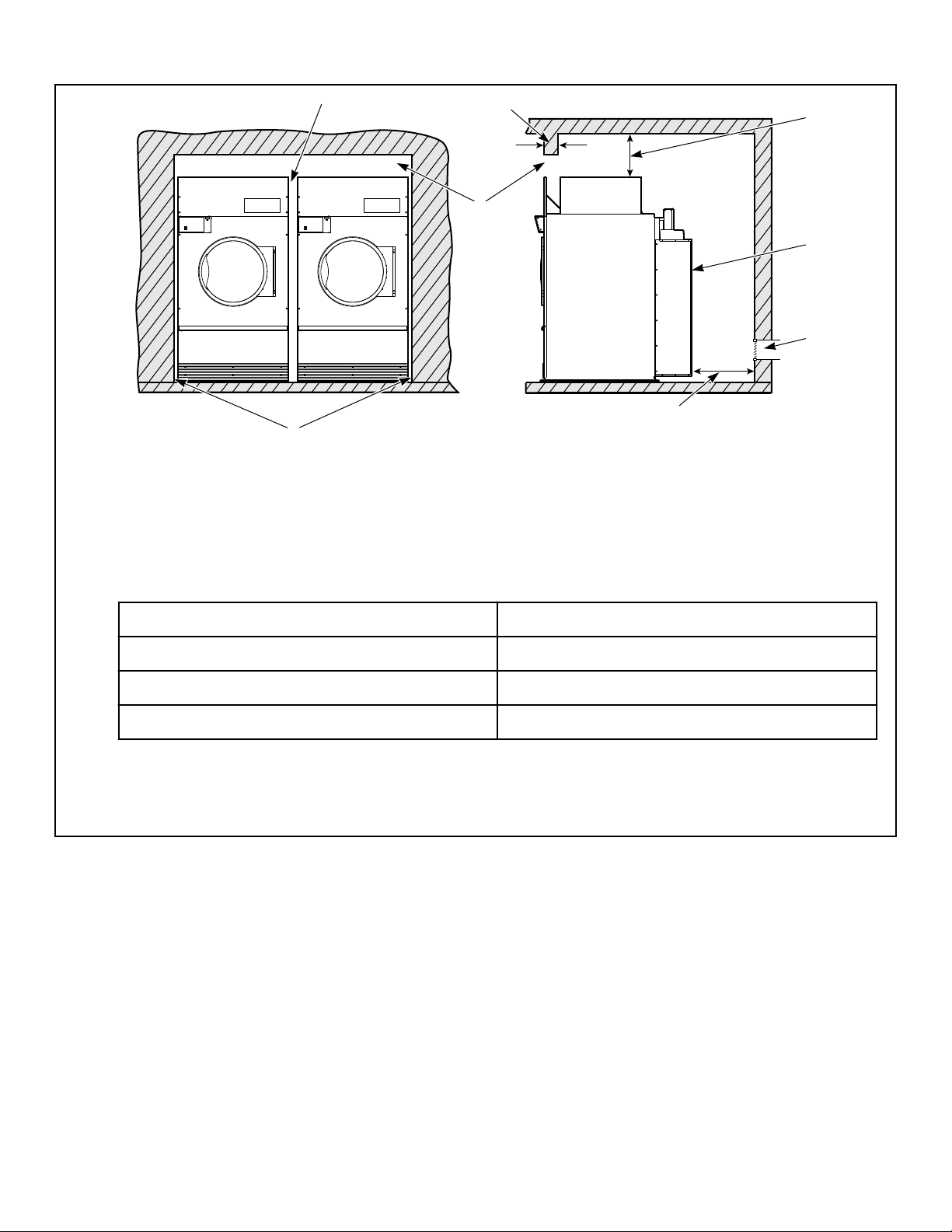
A typical tumble dryer enclosure is shown in Figure 2 .
IMPORTANT: Install tumble dryers with sufficient clear-
ance for servicing and operation, refer to Figure 2 .
WARNING
To reduce the risk of severe injury, clearance of tum-
bler cabinet from combustible construction must
conform to the minimum clearances, and/or local co-
des and ordinances.
W770
Installation
©
Copyright, Alliance Laundry Systems LLC -
DO NOT COPY or TRANSMIT
24 Part No. 70458101ENR11
TMB2020N_SVG
4
3
1
5
6
7
8
2
NOTE: Shaded areas indicate adjacent structure.
1. 0.5 in. [13 mm] recommended between machines for removal or installation
2. Allow 2-4 in. [51-102 mm] opening at top of machine to aid in removal or installation. A removable trim piece may be used to
conceal the opening; zero clearance allowed for trim.
3. 4 in. [102 mm] maximum header thickness
4. Minimum clearance permitted for remainder:
120 Gas/Electric 4 in. [101.6 mm]
120 Steam 6 in. [152.4 mm]
170/200 Gas 4 in. [101.6 mm]
170/200 Steam 8 in. [203.2 mm]
5. Guard
6. Provision for make-up air
7. 24 in. [610 mm] minimum, 36 in. [914 mm] recommended for maintenance purposes
8. 0.25 in. [6 mm] recommended for removal or installation purposes, zero clearance allowed
Figure 2
Position and Level the Tumble Dryer
The tumble dryer may be moved with or without the skid. To re-
move the skid, unscrew the four shipping bolts, and discard them.
To fit a 170 and 200 series tumble dryer (with shipping skid)
through a 8 foot [2.43 meters] high door, you must remove the
front access panel. The upper 3 inches [76 mm] of the stove must
also be removed on 170 series gas tumble dryers. Removing the
entire gas or steam heater assembly and the shipping skid, will re-
duce the height of the 120 series tumble dryer to 70 inches [1,778
mm], and the 170 and 200 series tumble dryer to 75 inches [1,905
mm].
Level the tumble dryer to within 0.125 inch [3 mm] from front-
to-rear (level on cylinder rib), and side-to-side (level on top pan-
el). Shim under corners to level and stabilize unit. Tumble dryer
must not rock.
Mounting
Where local code requires the unit to be securely mounted, use
the shipping bolt frame holes found on the tumble dryer frame.
Use either epoxy 1/2 in. [13 mm] bolts or equivalent 1/2 in. [13
mm] concrete anchors, such as expandable bolts.
Installation
©
Copyright, Alliance Laundry Systems LLC -
DO NOT COPY or TRANSMIT
25 Part No. 70458101ENR11

Fire Suppression System (Optional
Equipment)
WARNING
Electrical shock can result in death or serious injury.
If the water dispensing system is activated, do not
attempt to operate the tumble dryer. If the water dis-
pensing system is activated, have the tumble dryer
inspected by a qualified agency before operating the
tumble dryer.
W879
Check Local Codes and Permits
Call your local water company or the proper municipal authority
for information regarding local codes.
IMPORTANT: It is your responsibility to have ALL
plumbing connections made by a qualified professio-
nal to assure that the plumbing is adequate and con-
forms to local, state, and federal regulations or codes.
IMPORTANT: It is the installation or owner’s responsi-
bility to see that the necessary or required water, water
pressure, pipe size, or connections are provided. Man-
ufacturer assumes no responsibility if the fire suppres-
sion system is not connected, installed, or maintained
properly.
Water Requirements
IMPORTANT: Water must be supplied to the fire sup-
pression system, or the fire suppression system will
not operate as intended.
Connection point to the electric water solenoid valve is a 3/4 inch
[19 mm] hose. The fire suppression system equipped tumble dry-
er must be supplied with a minimum water pipe size of 1/2 inch
[12.7 mm] and be provided with a minimum of 20 psi [138 kPa]
and a maximum of 120 psi [827 kPa] of pressure at all times.
Flowrate must be no less than, but approximately 15 gallons [57
liters] per minute.
NOTE: Water pressure under 20 psi [138 kPa] will
cause low flow and water leakage at water solenoid
valve.
If the rear of the tumble dryer or the water supply is located in an
area where it will be exposed to cold/freezing temperatures, pro-
visions must be made to protect these water lines from freezing.
IMPORTANT: Temperature of the water supply must be
kept between 40°F and 120°F [4.4°C and 48.9°C] . If wa-
ter in the supply line or water solenoid valve freezes,
the fire suppression system will not operate.
IMPORTANT: If temperature sensors inside the tumble
dryer register a temperature below 40F° [4.4°C] , the
fire suppression system control will lock out. This fea-
ture protects against operation of the tumble dryer with
a possible frozen water supply. Only when the tempera-
ture sensors register a temperature above 40F° [4.4°C]
will the machine reset for operation.
IMPORTANT: Flexible supply line/coupling must be
used. Solenoid valve failure due to hard plumbing con-
nections will void the warranty. It is recommended that
a filter or strainer be installed in the water supply line.
Water Connections
Connect machine to a backflow preventer (vacuum breaker) be-
fore connecting to the public water main in all countries where
local regulations require specific water approval certificates.
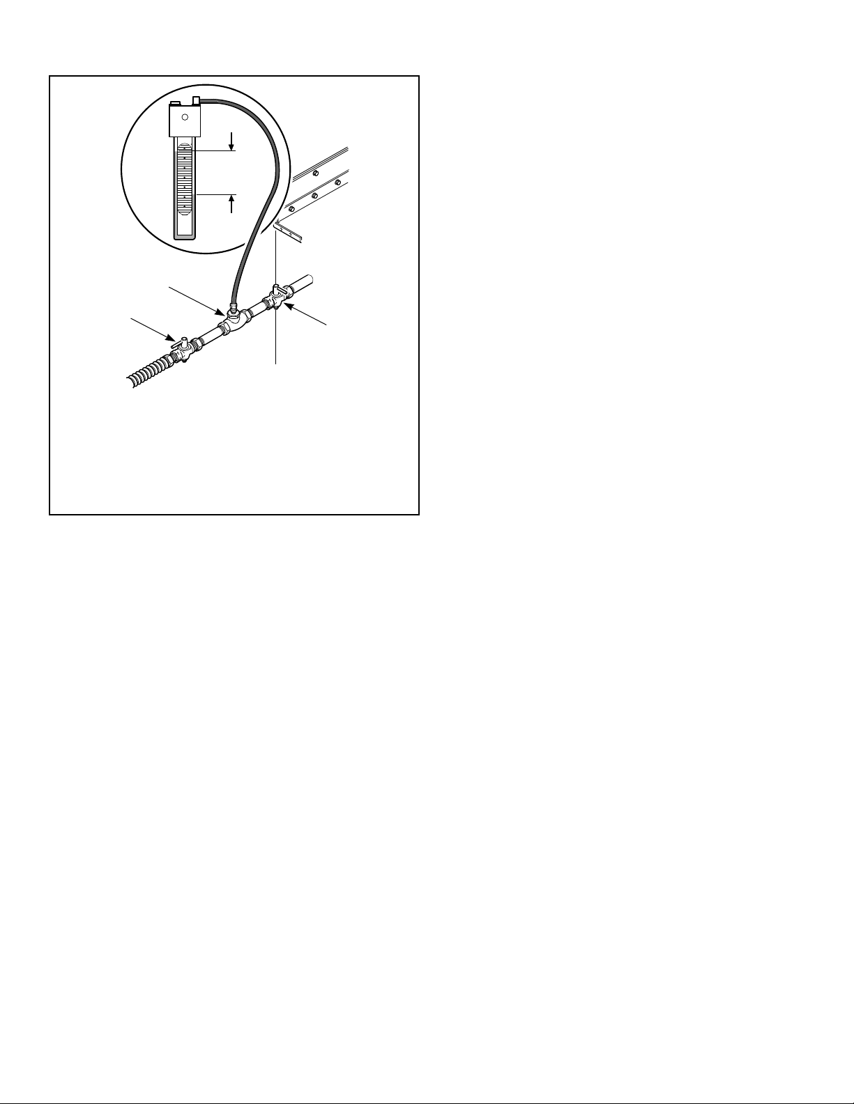
Two hoses and a Y-valve are provided with the tumble dryer to
allow for connection of water supply to tumble dryer. The water
connections are made to the bushings of the water solenoid valve,
located on the rear of the tumble dryer. The Y-valve provides a
single female hose connection (Standard US 3/4-11 1/2 NH
thread). Refer to Figure 3 and Figure 4 .
Installation
©
Copyright, Alliance Laundry Systems LLC -
DO NOT COPY or TRANSMIT
26 Part No. 70458101ENR11
TMB2012N_SVG
2
1
3
3
170/200
120
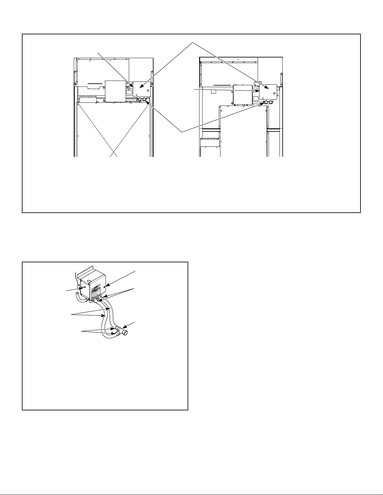
1. Fire Suppression System Control Box
2. Water Solenoid Valve
3. Opening for Auxiliary Alarm Cable
Figure 3
To connect the two hoses (supplied with tumble dryer), insert
rubber washers (from literature pack) in water inlet hose cou-
plings. Refer to Figure 4 .
TMB2008N_SVG
3
2
4
5
2
1
1. Lock
2. Hose Couplings
3. Y Valve
4. Inlet Hoses
5. Opening for Auxiliary Alarm Cable
Figure 4
Connect inlet hoses to water supply. Flush the lines for approxi-
mately two minutes to remove any foreign materials that could
clog the screens in the water mixing valve. This is especially im-
portant when installing a tumble dryer in a newly constructed or
renovated building. Then connect the hoses to the Y-valve; con-
nect the Y-valve to the connections at the rear of the tumble dry-
er.
IMPORTANT: Thread hose couplings onto valve con-
nections finger tight, then turn 1/4 turn with pliers. Do
not cross thread or overtighten couplings.
IMPORTANT: Hoses and other natural rubber parts de-
teriorate after extended use. Hoses may develop
cracks, blisters or material wear from the temperature
and constant high pressure they are subjected to. All
hoses should be checked on a yearly basis for any visi-
ble signs of deterioration. Any hose showing the signs
of deterioration listed above should be replaced imme-
diately. All hoses should be replaced every five years.
NOTE: Longer inlet hoses are available (as optional
equipment at extra cost) if the hoses supplied with the
tumble dryer are not long enough for installation. Order
hoses as follows:
Part No. 20617 Inlet hose 8 feet [2.44 m]
Part No. 20618 Inlet hose 10 feet [3.05 m]
NOTE: Replacement outlet hoses are available (at extra
cost). Order 44073302 Hose, 21 in. [53 cm ] for 120 ser-
ies and 44073303, 31 in. [79 cm] for 170 and 200 series.
Installation
©
Copyright, Alliance Laundry Systems LLC -
DO NOT COPY or TRANSMIT
27 Part No. 70458101ENR11
Electrical Requirements
WARNING
Electrical power must be provided to tumbler at all
times. The fire suppression system will be inopera-
tive if the main electrical power supply is discon-
nected.
W690
No independent external power source or supply connection is
necessary. Power to operate the 24 Volt fire suppression system is
from the rear junction/contactor box.
Auxiliary Alarm
The fire suppression system provides an auxiliary output signal
when the system is activated. During tumble dryer installation,
you have the option to connect a separate alarm system to this
auxiliary output. Potential uses of the auxiliary output include,
but are not limited to: (1) sounds an alarm, (2) activates a build-
ing sprinkler system, (3) notifies a fire department, etc. Use of the
auxiliary output is not required for the fire suppression system to
operate, but may be used for additional protection.
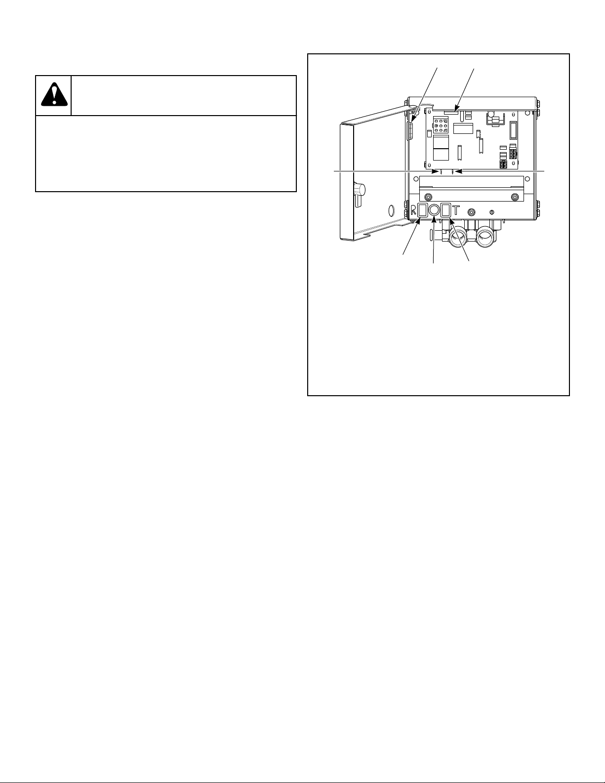
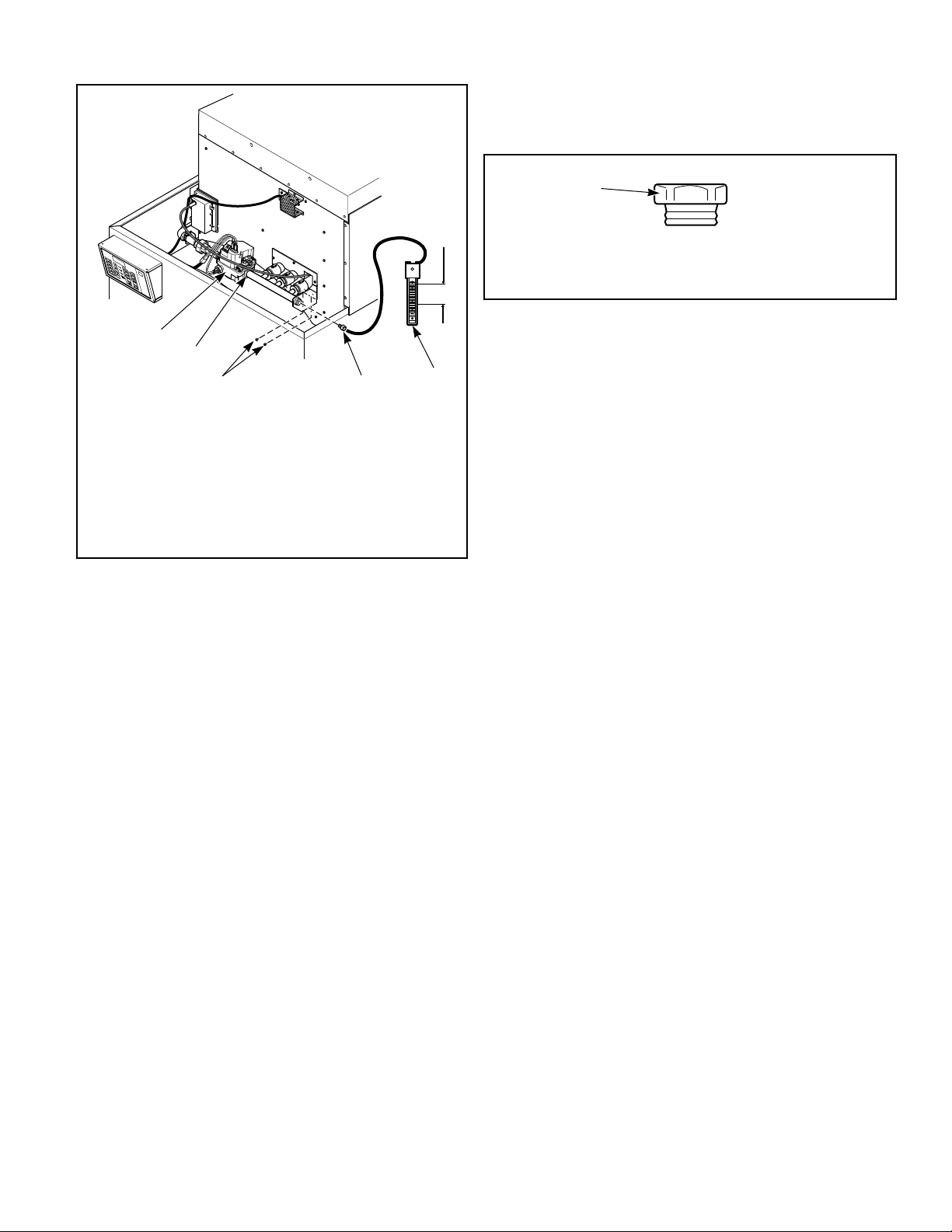
The connection to the auxiliary output is made through the FS-1
and FS-2 fast-on connections inside the fire suppression control
box. Refer to Figure 5 . The relay is rated for 24 VAC, 5.2 Amp,
sealed current.
NOTE: The auxiliary output is activated during fire sup-
pression system maintenance test sequence. Consider
this fact prior to your system test every three months.
(Example: If the external system uses the auxiliary out-
put to call the fire department, inform the fire depart-
ment before and after the fire suppression system
maintenance test.)
TMB1999N_SVG1
6
7
5
4
3
1 2
1. Opening for Auxiliary Alarm Cable
2. Fuse
3. Auxiliary Alarm Fast-On Connection
4. Test Button
5. Light
6. Reset Button
7. Auxiliary Alarm Fast-On Connection
Figure 5
Before Placing Tumble Dryer into Serv-
ice
1. Remove or open all panels and check accessible bolts, nuts,
screws, terminals and fittings for tightness.
2. Check belt tension and adjust if necessary. Refer to Adjust-
ments section.
3. Replace all panels and guards.
4. Turn on electrical supply to tumble dryer.
5. Open the supply valve for gas or steam heated tumble dryers.
6. After performing the previous checks, start the tumble dryer
by pressing START. (Refer to the Operating section for de-
tailed instructions.) Release the start button and open the
loading door. The cylinder should stop rotating within seven
seconds after the door is opened a maximum of 2 inches [51
mm]. If it does not, adjust the loading door switch. Refer to
Adjustments section.
7. Gas Tumble Dryers: Start the tumble dryer and check the
burner flame. Adjust the air inlet shutter as required. Refer to
Adjustments section.
Installation
©
Copyright, Alliance Laundry Systems LLC -
DO NOT COPY or TRANSMIT
28 Part No. 70458101ENR11
IMPORTANT: The electronic ignition system will at-
tempt to light the gas by sparking for the “trial for
ignition” period. If gas does not ignite within this
period, the ignition control will go into a safety lock-
out and the valve will no longer open until the con-
trol is reset. It may be necessary to retry several
times to bleed air from the gas lines. To reset, open
and close the loading door and restart tumble dryer.
If lockout condition persists, check that the manual
gas shut-off valve is in the ON position and that the
gas service is properly connected. If condition still
persists, remove tumble dryer from service.
8. Load the cylinder with a full load of clean rags and run to re-
move oil or dirt from cylinder.
9. Check the airflow switch operation by opening the lint panel;
be sure to remove shipping tape from airflow switch prior to
operation. Temporarily tape down the lint panel safety switch
located behind the upper left corner of the lint panel. The
heating systems should shut off when the lint panel is opened
a maximum of 6 inches [152.4 mm].
The airflow switch operation may be affected by shipping tape
still in place, lack of make-up air, or an obstruction in the exhaust
duct. These should be checked. If there is a problem, contact an
authorized service person.
WARNING
Do not operate tumble dryer if airflow switch is
faulty. An explosive gas mixture could collect in
tumble dryer if airflow switch does not operate
properly.
W407R1
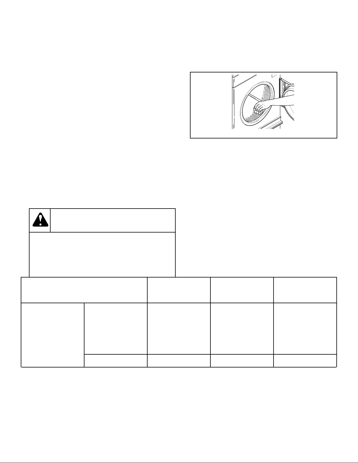
10. Wipe out the cylinder using an all-purpose cleaner or deter-
gent and water solution. Refer to Figure 6 .
IMPORTANT: The use of chlorine bleach for remov-
ing any discoloration should be avoided because
bleach could damage the finish.
T452I_SVG
Figure 6
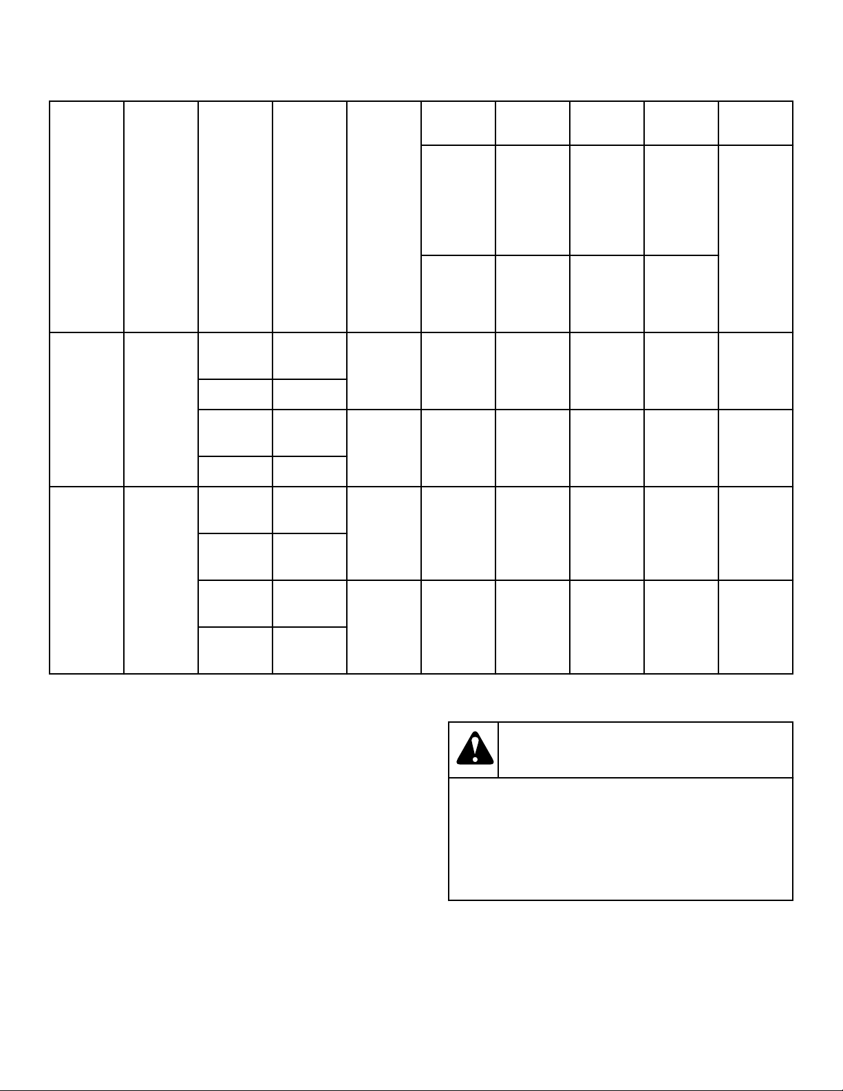
Models
Prepurge Time
(seconds)
Trial for Ignition
(seconds)
Reset Lockout
Condition By:
Models through
3/10/13
CE and
Australia
18 10 025, 030, 035, 055:
Press reset button on
rear of machine
T30, T45: Press lighted
reset button in rear
contactor box
All others 1-3 10 Open loading door
Table continues...
Installation
©
Copyright, Alliance Laundry Systems LLC -
DO NOT COPY or TRANSMIT
29 Part No. 70458101ENR11

Models
Prepurge Time
(seconds)
Trial for Ignition
(seconds)
Reset Lockout
Condition By:
Models starting 3/11/13
through 12/31/13
CE 1 10
(attempts to ignite 3
times)
For models with EO,
RE, RU or UO control
suffixes: Press start on
control keypad.
For models with all
other control suffixes:
Press and hold reset
button on junction box
until light goes out.
Models Starting 3/11/13 Non-CE and non-Aus-
tralian
1 10
(attempts to ignite 3
times)
Open loading door
Models starting 3/11/13
through 7/31/13
Australia 18 10 025, 030, 035, 055:
Press reset button on
rear of machine
T30, T45: Press lighted
reset button in rear
contactor box
Models starting 8/1/13 Australia 23 23 For models with EO,
RE, RU or UO control
suffixes: Press start on
control keypad.
For models with all
other control suffixes:
Press and hold ignition
control reset button.
Models Starting 1/1/14 CE
If the tumble dryer does not meet ANY of the listed requirements, remove tumble dryer from use. Refer to Removing Tumble Dryer
from Service section.
Required for CE Models Only
Once machine is installed, please be sure to complete the follow-
ing items:
• Review and verify machine operation with customer.
• Leave all literature and a signed Declaration of Conformity
with customer.
• Review machine warranty information with customer.
• Apply warning sticker on front panel of machine, in language
appropriate to country of sale (included in literature packet).
Installing CE Gas Drying Tumble Dryer
General Information
This information is to be used when installing gas tumble dryers
in countries and/or on gases different than the machine’s factory
configuration. Tumble Dryers are supplied from the factory for
operation on Natural Gas 1000 Btu/cu. ft. [8914 kcal/m
3
], or L.P.
Gas 2500 Btu/cu. ft. [22,250 kcal/m
3
], with natural gas group
H/E, designation G20 and L.P. gas group B/ P, designation G30.
To install machines in any other country, or on any other gas, re-
quires some level of modification.
Machines are built in two different configurations:
• Natural Gas – regulated/governor
• Liquefied Petroleum (L.P.) Gas – not regulated/no governor
For converting from Natural Gas to L.P. Gas, order 44240401P
L.P. Valve Conversion kit and orifice. Refer to CE Orifices.
Serial plates supplied from the factory are configured for
GB/IE/PT/ES/IT/GR/LU/CH/BE. These instructions pertain to
the situations when the country of use or gas supply is different
than that on the serial plate. If applicable, peel off the appropriate
Installation
©
Copyright, Alliance Laundry Systems LLC -
DO NOT COPY or TRANSMIT
30 Part No. 70458101ENR11

country sticker (included with machine) and apply it to the serial
plate over the existing country information.
These instructions are only valid if the following country code is
on the appliance: GB/IE/PT/ES/IT/GR/LU/CH/BE. If this code is
not present on the appliance, it is necessary to refer to the techni-
cal instructions which will provide the necessary information
concerning the modification of the appliance to the condition of
use for the country.
Before installation, check that the local distribution conditions,
nature of gas and pressure, and the adjustment of the appliance
are compatible.
Table 1 describes the different gases that are available in different
CE countries, and how the machines need to be configured to op-
erate with those gases. In the CE, there are Natural Gas configu-
rations that do not allow for machine regulation and L.P. Gas
configurations that must be regulated. For L.P. Gas, third family
B/P at 50 mbar (5 kPa), order Regulated Natural Gas machines
and convert according to Table 1 .
CE Orifices
Gas
Type
Gas
Fam-
ily
Grou
p
Gas
Desig-
nation
Supply
Pressure
in. wc
[mbar,
kPa]
Manifold
Pressure
in. wc
[mbar,
kPa]
Capaci-
ty/
Model
Orifice
Diam-
eter
inch
[mm]
Orifice
Part
Num-
ber
Quanti-
ty
Natural
Gas
Second I
2H(E)
G20 8/10 [20/25,
2/2.5]
3.57 [8.9,
0.89]
120 0.1695
[4.3]
M402988 3
170 0.1850
[4.7]
M411510 4
200 0.1890
[4.8]
M411372 4
I
2L
G25 10 [25, 2.5] 5.06 [12.6,
1.26]
120 0.1695
[4.3]
M411373 3
170 0.1850
[4.7]
M411510 4
200 0.1890
[4.8]
M411372 4
I
2E+
G20 8 [20, 2.0] Unregulated 120 0.1417
[3.6]
M401014 3
170 0.1496
[3.8]
M402997 4
200 0.1520
[3.9]
M401020 4
Table 1 continues...
Installation
©
Copyright, Alliance Laundry Systems LLC -
DO NOT COPY or TRANSMIT
31 Part No. 70458101ENR11

Gas
Type
Gas
Fam-
ily
Grou
p
Gas
Desig-
nation
Supply
Pressure
in. wc
[mbar,
kPa]
Manifold
Pressure
in. wc
[mbar,
kPa]
Capaci-
ty/
Model
Orifice
Diam-
eter
inch
[mm]
Orifice
Part
Num-
ber
Quanti-
ty
LP Third I
3B/P
G30 11.25/12
[28/30,
2.8/3.0]
Unregulated 120 0.0980
[2.5]
M406361 3
170 0.1200
[3.0]
M401017 3
200 0.1220
[3.1]
70070903 3
G30 14.9/20
[37/50,
3.7/5.0]
12.05 [30,
3.0]
120 0.0980
[2.5]
M406361 3
170 0.1200
[3.0]
M401017 3
200 0.1220
[3.1]
70070903 3
I
3+ / 3P
G30 /
G31
11.25/14.9
[28/37,
2.8/3.7]
Unregulated 120 0.0980
[2.5]
M406361 3
170 0.1200
[3.0]
M401017 3
200 0.1220
[3.1]
70070903 3
Table 1
Installation
©
Copyright, Alliance Laundry Systems LLC -
DO NOT COPY or TRANSMIT
32 Part No. 70458101ENR11
Properties of CE Gases
Gas
Type
Gas
Fami-
ly Group
Gas
De-
scrip-
tion
Gas
Desig-
nation
Wi Hi Ws Hs d
Wobb
e In-
dex
(net)
Heat-
ing
Value
(net)
Wobb
e In-
dex
(gross
)
Heat-
ing
Value
(gross
)
Densi-
ty
Btu/ft
3
[MJ/m
3
]
Btu/ft
3
[MJ/m
3
]
Btu/ft
3
[MJ/m
3
]
Btu/ft
3
[MJ/m
3
]
Natural
Gas
Second I
2H,E
Not Ap-
plicable
G20 1226
[45.67]
913
[34.02]
1362
[50.72]
1014
[37.78]
0.555
I
2E+
2H
I
2L
Not Ap-
plicable
G25 1004
[37.38]
785
[29.25]
1115
[41.52]
872
[32.49]
0.612
I
2E+
2L
LP Third I
3B/P
Not Ap-
plicable
G30 2164
[80.58]
3117
[116.09]
2345
[87.33]
3378
[125.81]
2.075
I
3+
Pure Bu-
tane
I
3+
Pure Pro-
pane
G31 1898
[70.69]
2363 [88] 2063
[76.83]
2568
[95.65]
1.55
I
3P
LPG with
Propane
Table 2
Changing Gas Configuration
1. Determine the necessary conversion operations to convert
from the factory-supplied configuration to the desired config-
uration.
2. Perform the conversions required so the machine is properly
configured for the desired country and gas. Refer to the fol-
lowing sections:
• How to Convert Gas Valve from Regulated to Unregulated
• How to Change Burner Orifice Size
• How to Adjust Gas Valve Governor/Regulator
WARNING
When converting the tumble dryer to a different
gas or pressure, first verify that the supply inlet
pressure is equipped with a pressure regulator
(located ahead of the tumble dryer) that will main-
tain the gas supply at the inlet pressure specified.
W430R1
Installation
©
Copyright, Alliance Laundry Systems LLC -
DO NOT COPY or TRANSMIT
33 Part No. 70458101ENR11
TMB2328N_SVG
4
3
2
1
1. Gas Shut-Off Valve (Ahead of pressure tap) (Not Supplied)
2. Pressure Tap
3. Gas Shut-Off Valve (Shown in closed position) (Not Sup-
plied)
4. Specified Local Inlet Pressure
Figure 7
Specific Conversion Procedures
How to Convert Gas Valve from Regulated to Unregu-
lated
NOTE: Conversion from regulated to unregulated is on-
ly needed when regulated tumble dryers were ordered,
but unregulated tumble dryers were needed.
1. Disconnect electrical power from tumble dryer. Close gas
shut-off valve to tumble dryer. Refer to Figure 7 .
2. Follow instructions in Conversion Kit.
Models through
3/10/13
Part No. M400763 (two kits
required)
Models starting
3/11/13
Part No. 44240401P
NOTE: These kits do not contain any burner orifi-
ces.
3. Replace burner orifice(s) as per Table 1 .
4. If applicable, peel off the appropriate conversion sticker (in-
cluded with machine) and apply it to the serial plate over the
“ADJUSTED FOR ______ GAS: ______” information.
5. Commission tumble dryer for use.
How to Change Burner Orifice Size
1. Disconnect electrical power from tumble dryer. Close gas
shut-off valve to tumble dryer. Refer to Figure 7 .
Installation
©
Copyright, Alliance Laundry Systems LLC -
DO NOT COPY or TRANSMIT
34 Part No. 70458101ENR11
S
T
A
TUS
D
R
YING
COO
L
DOWN
DOOR OPEN
CUS
T
OM
HIGH
MEDIUM
MED LOW
LOW
NO HE
A
T
TEMP
DISP
L
A
Y
SIGNAL
F/ C
TEMP
PROGRAM
AU
T
O
SPECIAL
CYCLE
MORE
CONDITION
SPECIAL
TIME
COOL
DOWN
LESS
S
A
VE
CUS
T
OM
TIME
*
+
-
-
*
PROG
AU
T
O
AU
T
O
ON / SELECT
S
T
ART
S
T
OP/RESET
REVERSING
TMB2402N_SVG
6
1
2
3
4
5
1. Manometer
2. Pressure Tap
3. Burner Tube Attaching Screws
4. Gas Valve Flange
5. Gas Valve
6. Specified Pressure
Figure 8
2. Remove gas valve:
a. Remove the burner orifice(s) from the spud holder.
b. When converting from Natural Gas to L.P. Gas, the left-
most burner and orifice (viewed from front) must be re-
moved.
c. In place of the removed orifice, a blank orifice (Part No.
M400995) and a Burner Opening Cover (Part No.
M413099) must be installed.
3. Install the new, correct burner orifice(s). Refer to Figure 9
and Table 1 . Torque each to 9 – 10 Nm.
4. Reinstall spud holder assembly to gas valve, making certain
burner orifice(s) are in line with burner tube opening. Refer to
Figure 9 .
5. Commission tumble dryer for use.
NOTE: Blank burner orifices are Part No. M400995.
How to Adjust Gas Valve Governor/Regulator
1. Check gas burner orifice (manifold) pressure as follows. Re-
fer to Figure 8 .
2. Remove screw plug from pressure tap.
3. Connect a “U”-tube manometer (or similar pressure gauge) to
the burner orifice (manifold) pressure tap.
4. Start tumble dryer and note pressure once flame is burning.
Remove regulator cap and adjust regulator screw until the
burner orifice pressure per applicable table is achieved. Re-
place regulator cap. Refer to Figure 8 .
5. Commission tumble dryer for use.
Burner Orifice
TMB2015N_SVG
1
1. Size Stamped on Orifice
Figure 9
Installation
©
Copyright, Alliance Laundry Systems LLC -
DO NOT COPY or TRANSMIT
35 Part No. 70458101ENR11
Exhaust Requirements
Exhaust Requirements
WARNING
A drying tumble dryer produces combustible lint. To
reduce the risk of fire, the tumble dryer must be ex-
hausted to the outdoors.
W057R1
WARNING
To reduce the risk of fire, DO NOT use plastic or thin
foil ducting to exhaust the tumbler.
W773
WARNING
To reduce the risk of fire and accumulation of com-
bustible gases, DO NOT exhaust tumble dryer air in-
to a window well, gas vent, chimney or enclosed, un-
ventilated area such as an attic wall, ceiling, crawl
space under a building, or concealed space of a
building.
W059R1
Layout
Whenever possible, install tumble dryers along an outside wall
where duct length can be kept to a minimum, and make-up air
can be easily accessed. Construction must not block the airflow at
the rear of the tumble dryer. Doing so would prevent adequate air
supply to the tumble dryer combustion chamber.
Make-Up Air
A tumble dryer is forced air exhausted and requires provisions for
make-up air to replace air exhausted by tumble dryer.
IMPORTANT: Do not obstruct flow of combustion and
ventilation air.
Required Make-Up Air Opening (to the outside) for
Each Tumble Dryer
Model Opening
120 Series 360 in.
2
[232,258 mm
2
]
170 Series 525 in.
2
[338,709 mm
2
]
200 Series 525 in.
2
[338,709 mm
2
]
Make-up air openings with louvers will restrict airflow. The
opening must be increased to compensate for area taken up by
louvers.
Make-up air openings in rooms containing tumble dryer(s) and/or
gas fired hot water heater or other gravity vented appliances must
be increased sufficiently to prevent downdrafts in any of the
vents when all tumble dryers are in operation. Do not locate grav-
ity vented appliances between tumble dryer(s) and make-up air
openings. If it is necessary to duct make-up air to tumble dry-
er(s), increase area of duct work by 25% to compensate for re-
strictions in air movement.
Venting
WARNING
To reduce the risk of fire due to increased static
pressure, we do not recommend installation of in-
line secondary lint filters or lint collectors. If secon-
dary systems are mandated, frequently clean the
system to assure safe operation.
W749
IMPORTANT: Installing in-line filters or lint collectors
will cause increased static pressure. Failure to main-
tain the secondary lint system will decrease tumble
dryer efficiency and may void machine warranty.
For maximum efficiency and minimum lint accumulation, tumble
dryer air must be exhausted to the outdoors by the shortest possi-
ble route.
Proper sized exhaust ducts are essential for proper operation. All
elbows should be sweep type. Exhaust ducts must be assembled
so the interior surfaces are smooth, so the joints do not permit the
accumulation of lint. DO NOT use plastic, thin foil or Type B
flexible ducts - rigid metal ducts are recommended. Use exhaust
ducts made of sheet metal or other noncombustible material. DO
NOT use sheet metal screws or fasteners on exhaust pipe joints
which extend into the duct and catch lint. Use of duct tape or
Exhaust Requirements
©
Copyright, Alliance Laundry Systems LLC -
DO NOT COPY or TRANSMIT
36 Part No. 70458101ENR11
pop-rivets on all seams and joints is recommended, if allowed by
local codes.
Verify that old ducts are thoroughly cleaned out before installing
new tumble dryer(s).
WARNING
Improperly sized or assembled ductwork causes ex-
cess back pressure which results in slow drying, lint
collecting in the duct, lint blowing back into the
room, and increased fire hazard.
W355
NOTE: Exhaust ducts must be constructed of sheet
metal or other noncombustible material. Such ducts
must be equivalent in strength and corrosion resist-
ance to ducts made of galvanized sheet steel not less
than 0.0195 inches [0.495 mm] thick.
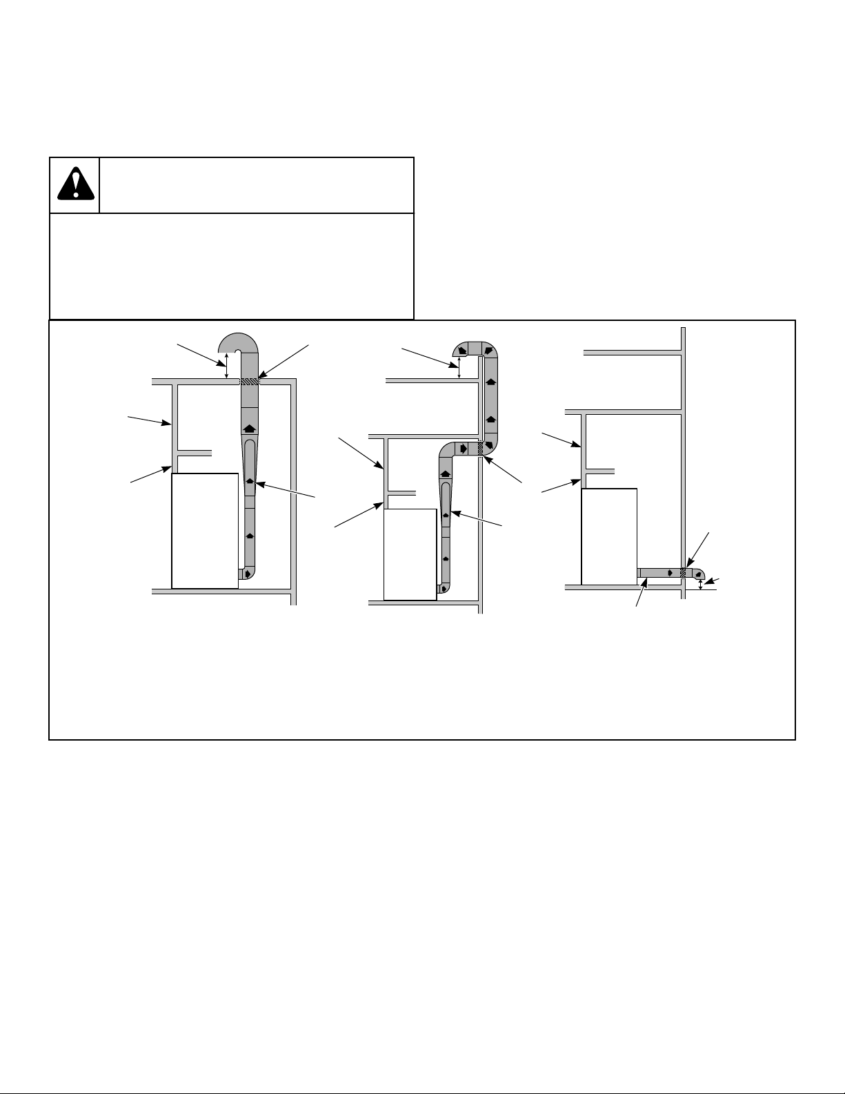
Where the exhaust duct pierces a combustible wall or ceiling, the
opening must be sized per local codes. The space around the duct
may be sealed with noncombustible material. Refer to Figure 10 .
IMPORTANT: For best performance provide an individ-
ual exhaust duct for each tumble dryer. Do not install a
hot water heater in a room containing tumble dryers. It
is better to have the water heater in a separate room
with a separate air inlet.
TMB2361N_SVG
5
4
3
2
1
TMB2362N_SVG
5
4
3
2
1
TMB2426N_SVG
5
4
3
2
1
1. Removable strip of panel in framing wall to permit removal of tumble dryer from framing wall
2. Partition or bulkhead
3. Minimum distance between exhaust opening and roof, ground or other obstruction: 36 in. [914 mm]
4. 2 in. [51 mm] minimum clearance on both sides of duct
5. Exhaust airflow – maximum length of rigid duct 14 ft. [4.3 m] or 7.87 ft. [2.4 m] of flexible metal duct
Figure 10
NOTE: Do not install wire mesh or screen in exhaust
duct opening to avoid lint build-up or impacting proper
discharge of air from tumble dryers.
NOTE: Where exhaust duct pierces a combustible wall
or ceiling, the opening must be sized per local codes.
NOTE: Inside of duct must be smooth. Do not use
sheet metal screws to join sections.
NOTE: Locate exhaust far enough away from make-up
air location to prevent re-introduction.
Consult your local building code for regulations which may also
apply.
Alternate Venting for 120 Series Tumble Dryers
The 120 series tumble dryer is equipped from the factory to exhaust from the top; however, it may be converted to exhaust out the rear
by doing the following (refer to Specifications and Dimensions section):
1. Remove belt guard cover. 2. Remove 10 inch [254 mm] diameter elbow and vertical duct.
Exhaust Requirements
©
Copyright, Alliance Laundry Systems LLC -
DO NOT COPY or TRANSMIT
37 Part No. 70458101ENR11
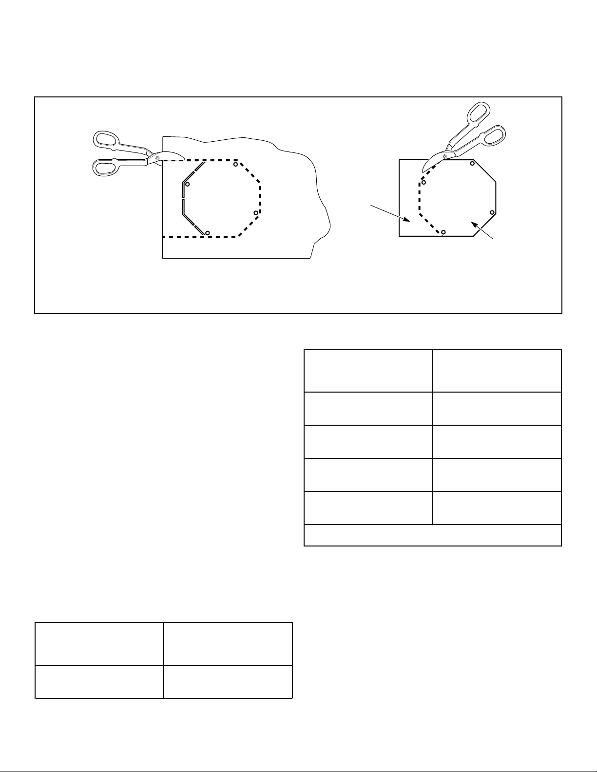
3. Cut out shape from belt guard cover. Refer to Figure 11 .
4. Screw octagonal piece over 10 inch [254 mm] diameter open-
ing in top of belt guard.
5. Attach new exhaust duct to exhaust thimble on rear panel, fol-
lowing all requirements in this section.
6. Replace belt guard cover.
T496I_SVG
B
A
A
2
1
1. Discard
2. Cover
Figure 11
Individual Venting
For maximum efficiency and performance, it is preferred to ex-
haust tumble dryer(s) individually to the outdoors.
IMPORTANT: At no point may the cross sectional area
of installed venting be less than the cross sectional
area of the exhaust outlet of the tumble dryer.
The exhaust duct must be designed so the static back pressure
measured 12 inches [305 mm] from the exhaust outlet does not
exceed the maximum allowable pressure specified in the Specifi-
cations and Dimensions Table or on the installation sticker on the
rear of the tumble dryer.
NOTE: Static back pressure must be measured with the
tumble dryer running.
The maximum allowable length venting is 14 feet [4.3 m] and
two 90° elbows or equivalent. If the equivalent length of a duct
required for an installation exceeds the maximum allowable
equivalent length, the diameter of a round duct must be increased
by 10% for each additional 20 feet [6.1 m]. Cross section area of
a rectangular duct must be increased by 20% for each additional
20 feet [6.1 m]. Refer to Table 3 to determine equivalent venting.
Duct Diameter
Equivalent Length of
Rigid Straight Duct
10 in. [254 mm] One 90° elbow = 11.6 ft. [3.5
m]
Table 3 continues...
Duct Diameter
Equivalent Length of
Rigid Straight Duct
12 in. [305 mm] One 90° elbow = 14 ft. [4.3
m]
14 in. [356 mm] One 90° elbow = 16 ft. [4.9
m]
16 in. [406 mm] One 90° elbow = 18.7 ft. [5.7
m]
18 in. [457 mm] One 90° elbow = 21 ft. [6.4
m]
Equivalent Length (meter) = 1.17 x Duct Diameter (mm)
Table 3
Example: A 12 inch [305 mm] diameter duct’s equivalent length
of 14 feet [4.3 m] of duct and two 90° elbows is:
Equivalent Length
= 14 ft. [4.3 m] + (2) 90° elbows
= 14 ft. [4.3 m] + 14 ft. [4.3 m] + 14 ft. [4.3 m]
= 42 ft. [12.8 m]
With the tumble dryer in operation, airflow at any point in the
duct should be at least 1200 feet/min. [366 m/min.] to ensure that
lint remains airborne. If 1200 feet/min. [366 m/min.] cannot be
Exhaust Requirements
©
Copyright, Alliance Laundry Systems LLC -
DO NOT COPY or TRANSMIT
38 Part No. 70458101ENR11
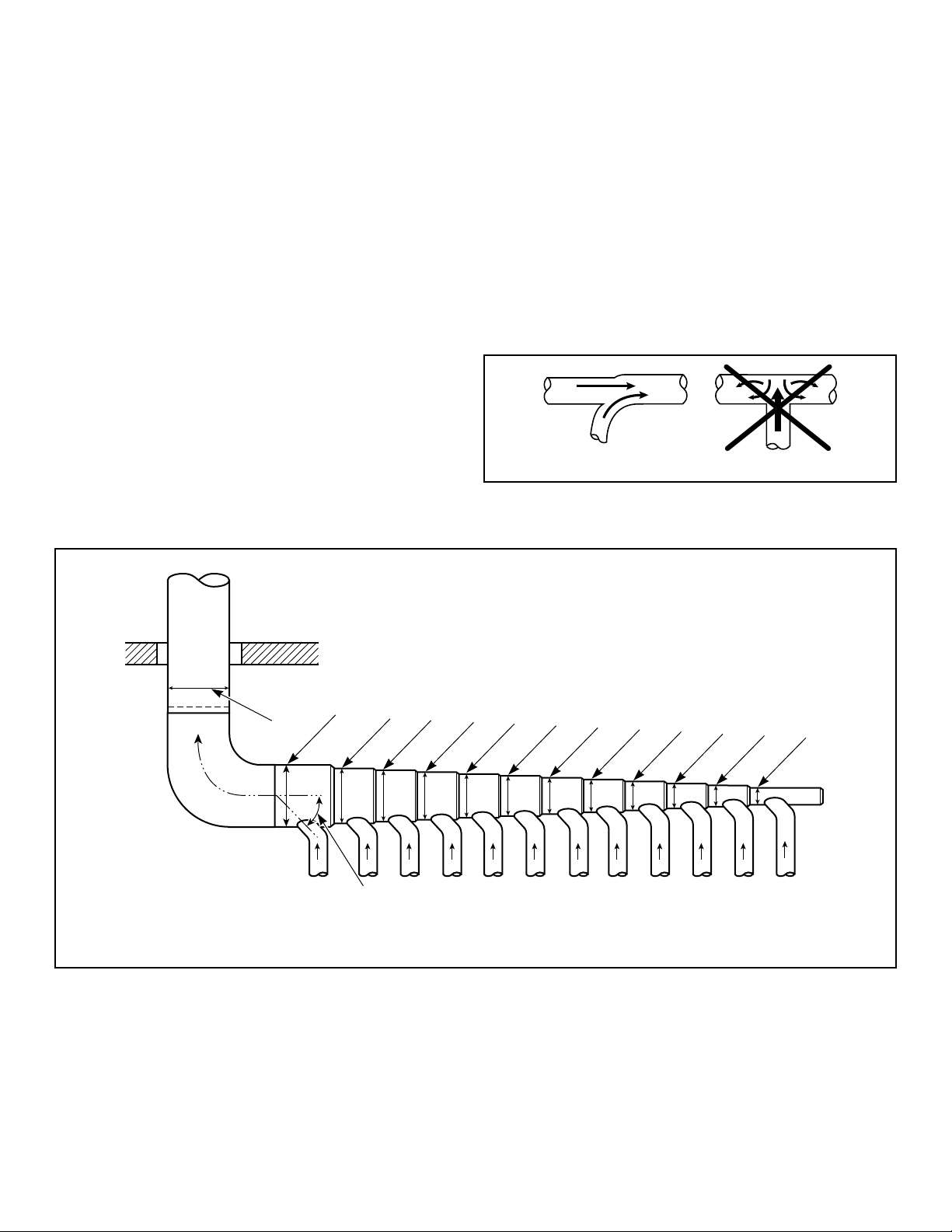
maintained, schedule monthly inspections and cleaning of the
ductwork.
NOTE: The maximum length of a flexible metal duct
must not exceed 7.87 ft. [2.4 m] as required to meet
UL2158, clause 7.3.2A.
Manifold Venting
While it is preferable to exhaust tumble dryers individually to the
outdoors, a main collector duct may be used if it is sized accord-
ing to Figure 13 and Figure 14 . This illustration indicates mini-
mum diameters, and should be increased if the collector length
exceeds 14 feet [4.3 m] and two 90° elbows. The diameter of a
round duct must be increased by 10% for each additional 20 feet
[6.1 m]. Cross sectional area of a rectangular or square duct must
be increased 20% for each additional 20 feet [6.1 m]. Refer to
Table 4 to determine equivalent ducting sizing. The collector duct
may be rectangular or square in cross section, as long as the area
is not reduced. Provisions MUST be made for lint removal and
cleaning of the collector duct.
The vent collector system must be designed so the static back
pressure measured 12 inches [305 mm] from the exhaust outlet
does not exceed the maximum allowable pressure specified in the
Specifications and Dimensions Table or on the installation sticker
on the rear of tumble dryer. Static back pressure must be meas-
ured with all tumble dryers vented into the collector operating.
NOTE: Never connect a tumble dryer duct at a 90° an-
gle to the collector duct. Refer to Figure 12 . Doing so
will cause excessive back pressure, resulting in poor
performance. Never connect two tumble dryer exhaust
ducts directly across from each other at the point of
entry to the collector duct.
With the tumble dryer in operation, airflow at any point in the
duct should be at least 1200 feet/min. [366 m/min.] to ensure that
lint remains airborne. If 1200 feet/min. [366 m/min.] cannot be
maintained, schedule monthly inspections and cleaning of the
ductwork.
T438i_SVG
Figure 12
One Manifold Assembly
TMB2403N_SVG
L
K
J
I
H
G
F
E
D
C
B
A
1
2
1. Outlet duct diameter = largest duct diameter based on number of units
2. 45° typical
Figure 13
Exhaust Requirements
©
Copyright, Alliance Laundry Systems LLC -
DO NOT COPY or TRANSMIT
39 Part No. 70458101ENR11

Duct Station 120 Series 170/200 Series
A 10 in. [254 mm] 12 in. [305 mm]
B 15 in. [381 mm] 17 in. [432 mm]
C 18 in. [457 mm] 21 in. [533 mm]
D 21 in. [533 mm] 24 in. [610 mm]
E 24 in. [610 mm] 27 in. [686 mm]
F 26 in. [660 mm] 30 in. [762 mm]
G 28 in. [711 mm] 32 in. [813 mm]
H 30 in. [762 mm] 34 in. [864 mm]
I 32 in. [813 mm] 36 in. [914 mm]
J 33 in. [838 mm] 38 in. [965 mm]
K 35 in. [889 mm] 40 in. [1,016 mm]
L 36 in. [914 mm] 42 in. [1,067 mm]
Table 4
NOTE: Table 4 represents units with the same vent size.
If multiple vent sizes are used, consult a local HVAC
specialist.
NOTE: Duct clean-out recommended every 6 feet [183
cm].
Exhaust Requirements
©
Copyright, Alliance Laundry Systems LLC -
DO NOT COPY or TRANSMIT
40 Part No. 70458101ENR11
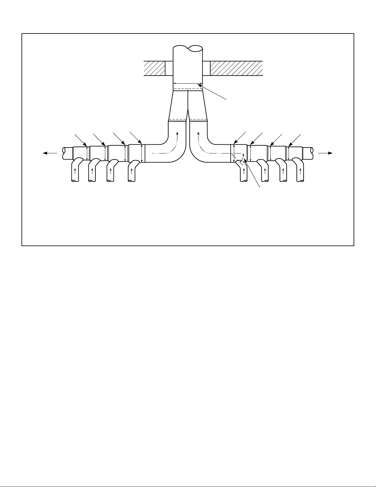
Two Manifold Assemblies
TMB2018N_SVG
1
2
L L
K K
J J
I
AA
I
1. Outlet duct diameter = combined largest duct diameter of both sides
2. 45° typical
Figure 14
Refer to Table 4 for measurements for each manifold.
Exhaust Requirements
©
Copyright, Alliance Laundry Systems LLC -
DO NOT COPY or TRANSMIT
41 Part No. 70458101ENR11
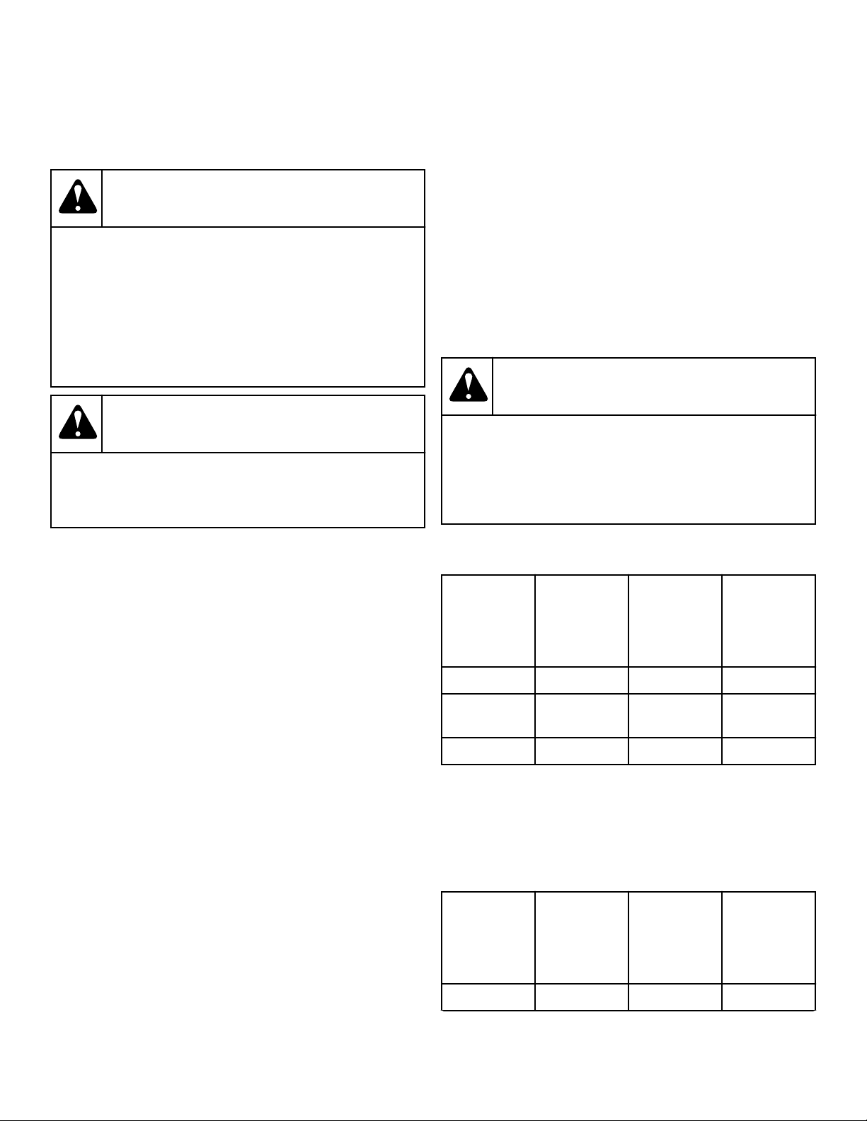
Gas Requirements
Gas Requirements
WARNING
To reduce the risk of fire or explosion, DO NOT CON-
NECT THE GAS LINE TO THE TUMBLE DRYER IF
THE GAS SERVICE IS NOT THE SAME AS THAT
SPECIFIED ON THE TUMBLE DRYER SERIAL PLATE!
It will first be necessary to convert the gas burner or-
ifice and gas valve. Appropriate conversion kits are
available.
W060R1
WARNING
To reduce the risk of gas leaks, fire or explosion, use
a new flexible stainless steel connector.
W774
IMPORTANT: Any product revisions or conversions
must be made by the Manufacturer’s Authorized Deal-
ers, Distributors or local service personnel.
IMPORTANT: The tumble dryer must be isolated from
the gas supply piping system by closing its individual
manual shut-off valve during any pressure testing of
the gas supply piping system at test pressure equal to
or less than 0.5 psig [3.45 kPa, 34.5 mbar].
NOTE: For gas valves with a manual shut-off switch on
the gas valve, the shut-off switch does not protect the
valve from this pressure test. Use the individual man-
ual shut-off valve from the gas supply piping system to
protect the gas valve.
IMPORTANT: The tumble dryer and its manually operat-
ed appliance gas valve must be disconnected from the
gas supply piping system during any pressure testing
of that system at test pressures in excess of 0.5 psig
[3.45 kPa, 34.5 mbar].
IMPORTANT: The installation must comply with local
codes or, in the absence of local codes:
• with the latest edition of the “National Fuel Gas
Code,” ANSI Z223.1/NFPA 54 in the U.S.A.
• with CAN/CSA-B149.1 Natural Gas and Propane In-
stallation Code in Canada
• In Australia and New Zealand , installation must
comply with the Gas Installations Standard AS/NZS
5601 Part 1: General Installations.
Obtain specific gas service pipe size from the gas supplier. Refer
to Table 5 and Table 6 for general pipe size.
The following must be furnished and installed by the customer
for the gas service line to each tumble dryer. Refer to Figure 15 .
• Sediment traps
• Shut-off valves
• Supply pressure taps
It is important that equal pressure be maintained at all tumble
dryer gas connections. This can be done by installing a 1 inch
[25.4 mm] pipe gas loop to maintain equal pressure at all gas
connections. Refer to Figure 16 .
WARNING
To reduce the risk of fire or explosion, if the tumble
dryer is to be connected to Liquefied Petroleum
(L.P.) gas, a vent to the outdoors must be provided in
the room where the tumble dryer is installed.
W062R1
NATURAL GAS pressures with all gas appliances running (tum-
ble dryers, water heaters, space heaters, furnace, etc.):
Non-CE
and Non-
Australian
Models
Australian
and Kore-
an Models
CE Mod-
els
Maximum 10.5 in. w.c. 2.61 kPa 26.1 mbar
Recommend-
ed
6.5 in. w.c 1.62 kPa 16.2 mbar
Minimum 5 in. w.c. 1.13 kPa 12.4 mbar
An in-line pressure regulator may be required if the line pressure
exceeds 10.5 water column inches [26.1 mbar, 2.61 kPa] with all
gas appliances running.
LIQUID PETROLEUM GAS (L.P.) pressures with all gas appli-
ances running (tumble dryers, water heaters, space heaters, fur-
nace, etc.):
Non-CE
and Non-
Australian
Models
Australian
and Kore-
an Models
CE Mod-
els
Maximum 13 in. w.c. 3.23 kPa 32.3 mbar
Table continues...
Gas Requirements
©
Copyright, Alliance Laundry Systems LLC -
DO NOT COPY or TRANSMIT
42 Part No. 70458101ENR11
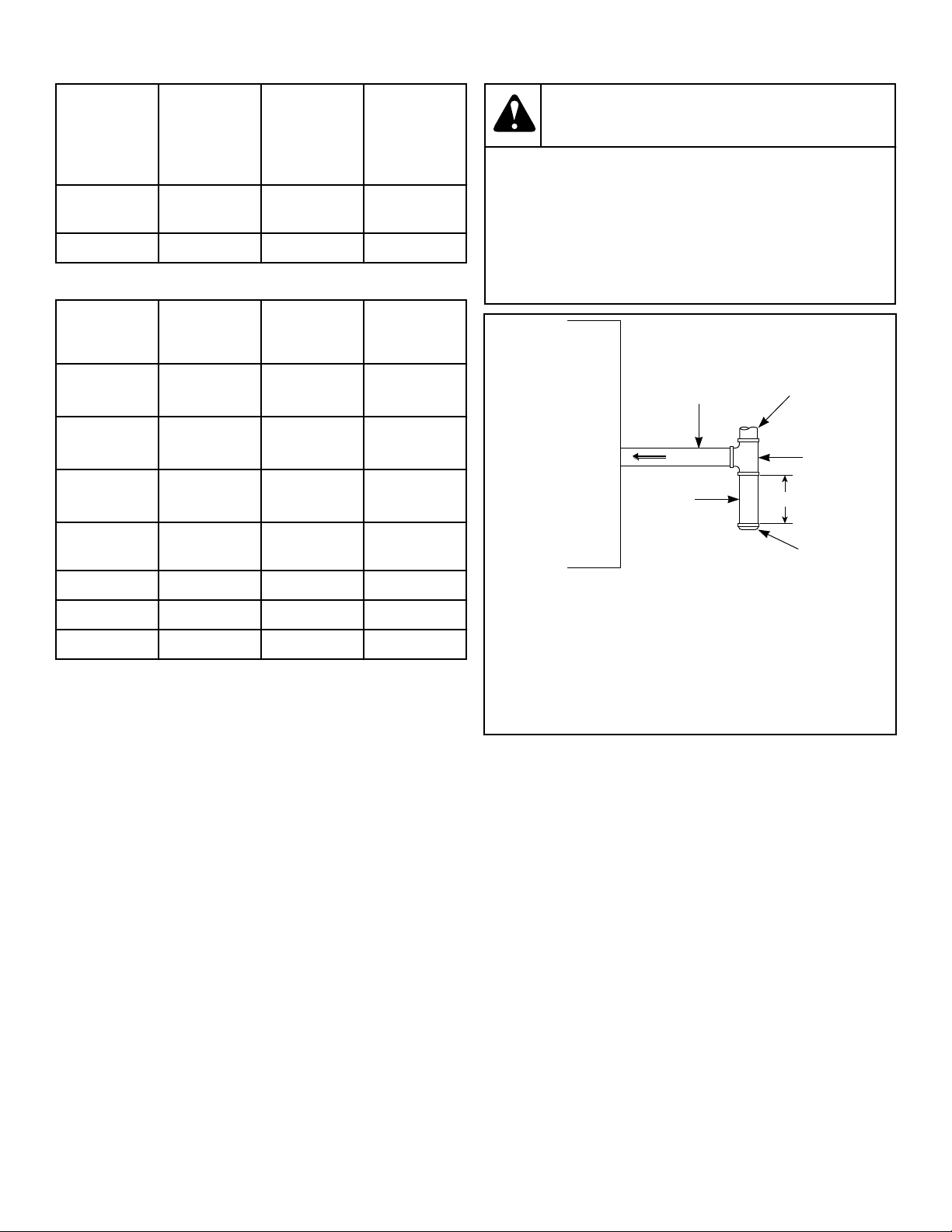
Non-CE
and Non-
Australian
Models
Australian
and Kore-
an Models
CE Mod-
els
Recommend-
ed
11 in. w.c. 2.74 kPa 27.4 mbar
Minimum 10 in. w.c. 2.49 kPa 24.9 mbar
For converting Non-CE models from Natural Gas to L.P. Gas:
Model Hertz
Date
Range Part No.
120 60 Through
2/14/11
M4577P3
120 60 Starting
2/15/11
M4578P3
120 50 Through
2/14/11
M4973P3
120 50 Starting
2/15/11
M4975P3
170 60 - M4592P3
170 50 - M4974P3
200 50 and 60 - 44257701
CE GASES refer to Installing CE Gas Drying Tumble Dryers
section, the above data does not apply to the CE.
Turn on gas and check all pipe connections (internal and external)
for gas leaks with a non-corrosive leak detection fluid. Purge air
in gas service line by operating the tumble dryers in the drying
mode. If burner does not light and unit goes into lockout, open
and close the door and restart. Repeat these steps until burner ig-
nites. Use pipe compound, resistant to actions of L.P. gas, on all
pipe threads.
WARNING
Check all pipe connections, internal and external, for
gas leaks using a non-corrosive leak detection fluid.
To reduce the risk of explosion or fire, DO NOT USE
AN OPEN FLAME TO CHECK FOR GAS LEAKS! Gas
connections should be checked twice a year for leak-
age.
W635
TMB2404N_SVG
6
3
4
5
1
2
1. Gas Line to Tumble Dryer
2. Gas Supply Piping System
3. Gas "T" Fitting
4. 3 in. [76 mm] Minimum Gas Pipe
5. Gas Pipe Cap
6. Sediment Trap
Figure 15
Gas Requirements
©
Copyright, Alliance Laundry Systems LLC -
DO NOT COPY or TRANSMIT
43 Part No. 70458101ENR11
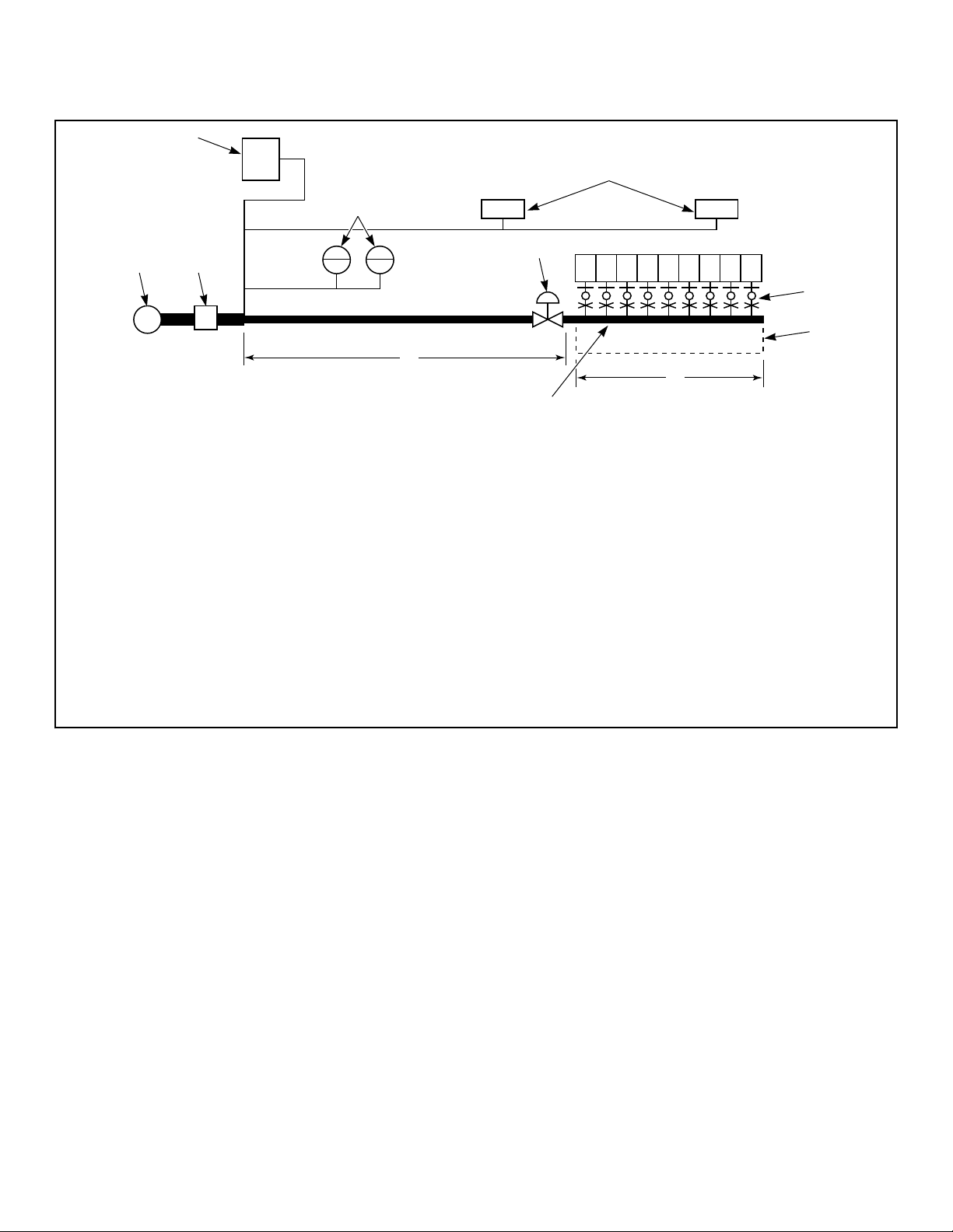
Gas Supply Pipe Sizing and Looping
TMB2126N_SVG
1 2 3 4 5 6 7 8 9
M
6
8
7
4
5
3
2
1
9 10
11
12
1. Gas furnace [120,000 Btu/hr. [127 Mj/hr., 35.2 kW]]
2. Gas water heaters [400,000 Btu/hr. [422 Mj/hr., 117.2 kW] each]
3. Gas space heaters [70,000 Btu/hr. [79 Mj/hr., 20.5 kW] each]
4. Sediment traps, supply pressure taps and shut-off valves. Refer to Figure 15 .
5. 1 in. [25.4 mm] gas pipe loop
6. 19 ft. [5.8 m]
7. Minimum Pipe Size is 0.75 in. [19 mm] for 120 Series Gas, 1 in. [25.4 mm] for 170 and 200 Series Gas.
8. 25 ft. [7.6 m]
9. Main regulator
10. Gas meter
11. Pressure regulator (if required)
12. 120 series tumble dryers = 270,000 Btu/hr. [285 Mj/hr.,79.13 kW] each; 170 series tumble dryers = 395,000 Btu/hr. [417 Mj/hr.,
115.77 kW] each; 200 series tumble dryers = 425,000 Btu/hr. [448 Mj/hr., 124.56 kW] each
Figure 16
SAMPLE CALCULATIONS:
Equivalent length = Total length of main gas supply pipe to
the far end of the tumble dryers.
= 25 ft. + 19 ft. [7.6 m + 5.8 m] gas supply pipe
= 44 ft. [13.4 m] Total Gas Line
Total Btu/hr. = The sum of the Btu/hr. of all 120 series tumble
dryers being fed by the main gas supply pipe.
= 9 x 270,000 [285, 79.13]
= 2,430,000 Btu/hr. [2,564 Mj/hr., 712.17 kW]
Using Table 5 , the main supply pipe diameter should be 3 in. [76
mm].
IMPORTANT: Gas loop piping must be installed as il-
lustrated to equalize gas pressure for all tumble dryers
connected to single gas service. Other gas using appli-
ances should be connected upstream from loop.
Low Pressure Gas Pipe Sizes
NOTE: Sizing calculations based on National Fuel Gas
Code.
Gas Requirements
©
Copyright, Alliance Laundry Systems LLC -
DO NOT COPY or TRANSMIT
44 Part No. 70458101ENR11
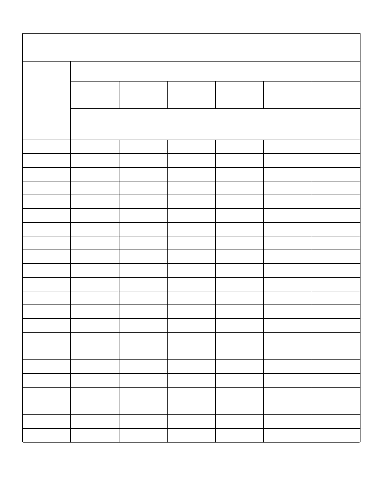
Gas Pipe Size Required for 1000 Btu Natural Gas (Standard Conditions) at Upstream Pressure— 7 ± 1.5 in-
ches [17.4 ± 4 mbar, 1.74 ± 0.37 kPa] Water Column Pressure
GasAp-
pliances
Total
Btu/hr.
Equivalent Length
25 feet
[7.63 m]
50 feet
[15.25 m]
75 feet
[22.88 m]
100 feet
[30.50 m]
125 feet
[38.13 m]
150 feet
[45.75 m]
Based on 0.3 in. Water Column Pressure Drop for Length Given
Sizes shown in inches [mm]
100,000 0.75 [19.05] 0.75 [19.05] 0.75 [19.05] 1 [25.40] 1 [25.40] 1 [25.40]
120,000 0.75 [19.05] 0.75 [19.05] 1 [25.40] 1 [25.40] 1 [25.40] 1 [25.40]
140,000 0.75 [19.05] 1 [25.40] 1 [25.40] 1 [25.40] 1 [25.40] 1 [25.40]
160,000 0.75 [19.05] 1 [25.40] 1 [25.40] 1 [25.40] 1.25 [31.75] 1.25 [31.75]
180,000 0.75 [19.05] 1 [25.40] 1 [25.40] 1.25 [31.75] 1.25 [31.75] 1.25 [31.75]
200,000 1 [25.40] 1 [25.40] 1 [25.40] 1.25 [31.75] 1.25 [31.75] 1.25 [31.75]
300,000 1 [25.40] 1.25 [31.75] 1.25 [31.75] 1.25 [31.75] 1.5 [38.10] 1.5 [38.10]
400,000 1.25 [31.75] 1.25 [31.75] 1.5 [38.10] 1.5 [38.10] 1.5 [38.10] 1.5 [38.10]
500,000 1.25 [31.75] 1.5 [38.10] 1.5 [38.10] 1.5 [38.10] 1.5 [38.10] 2 [50.80]
600,000 1.25 [31.75] 1.5 [38.10] 1.5 [38.10] 2 [50.80] 2 [50.80] 2 [50.80]
700,000 1.5 [38.10] 1.5 [38.10] 2 [50.80] 2 [50.80] 2 [50.80] 2 [50.80]
800,000 1.5 [38.10] 1.5 [38.10] 2 [50.80] 2 [50.80] 2 [50.80] 2 [50.80]
900,000 1.5 [38.10] 2 [50.80] 2 [50.80] 2 [50.80] 2 [50.80] 2.5 [63.50]
1,000,000 1.5 [38.10] 2 [50.80] 2 [50.80] 2 [50.80] 2.5 [63.50] 2.5 [63.50]
1,100,000 1.5 [38.10] 2 [50.80] 2 [50.80] 2 [50.80] 2.5 [63.50] 2.5 [63.50]
1,200,000 1.5 [38.10] 2 [50.80] 2 [50.80] 2.5 [63.50] 2.5 [63.50] 2.5 [63.50]
1,300,000 2 [50.80] 2 [50.80] 2.5 [63.50] 2.5 [63.50] 2.5 [63.50] 2.5 [63.50]
1,400,000 2 [50.80] 2 [50.80] 2.5 [63.50] 2.5 [63.50] 2.5 [63.50] 2.5 [63.50]
1,500,000 2 [50.80] 2 [50.80] 2.5 [63.50] 2.5 [63.50] 2.5 [63.50] 2.5 [63.50]
1,600,000 2 [50.80] 2 [50.80] 2.5 [63.50] 2.5 [63.50] 2.5 [63.50] 3 [76.20]
1,700,000 2 [50.80] 2.5 [63.50] 2.5 [63.50] 2.5 [63.50] 3 [76.20] 3 [76.20]
1,800,000 2 [50.80] 2.5 [63.50] 2.5 [63.50] 2.5 [63.50] 3 [76.20] 3 [76.20]
Table 5 continues...
Gas Requirements
©
Copyright, Alliance Laundry Systems LLC -
DO NOT COPY or TRANSMIT
45 Part No. 70458101ENR11
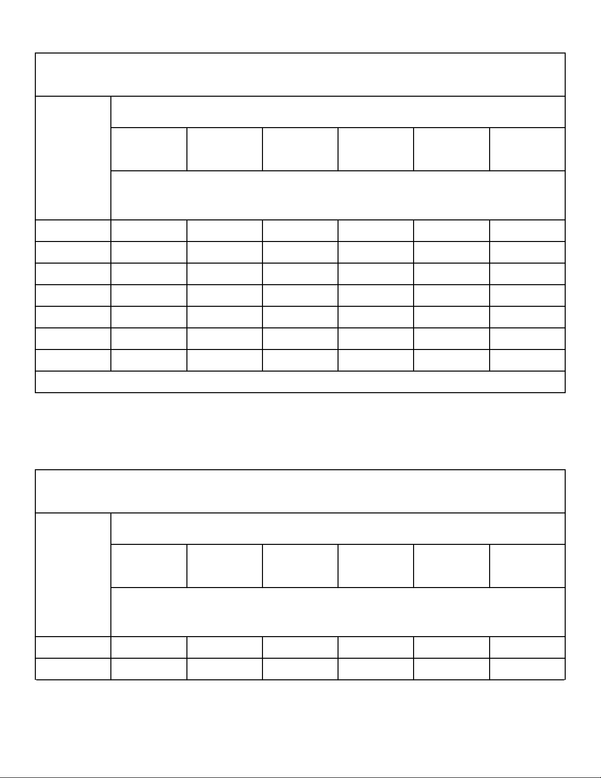
Gas Pipe Size Required for 1000 Btu Natural Gas (Standard Conditions) at Upstream Pressure— 7 ± 1.5 in-
ches [17.4 ± 4 mbar, 1.74 ± 0.37 kPa] Water Column Pressure
GasAp-
pliances
Total
Btu/hr.
Equivalent Length
25 feet
[7.63 m]
50 feet
[15.25 m]
75 feet
[22.88 m]
100 feet
[30.50 m]
125 feet
[38.13 m]
150 feet
[45.75 m]
Based on 0.3 in. Water Column Pressure Drop for Length Given
Sizes shown in inches [mm]
1,900,000 2 [50.80] 2.5 [63.50] 2.5 [63.50] 3 [76.20] 3 [76.20] 3 [76.20]
2,000,000 2 [50.80] 2.5 [63.50] 2.5 [63.50] 3 [76.20] 3 [76.20] 3 [76.20]
2,200,000 2 [50.80] 2.5 [63.50] 3 [76.20] 3 [76.20] 3 [76.20] 3 [76.20]
2,400,000 2.5 [63.50] 2.5 [63.50] 3 [76.20] 3 [76.20] 3 [76.20] 3.5 [88.90]
2,600,000 2.5 [63.50] 2.5 [63.50] 3 [76.20] 3 [76.20] 3.5 [88.90] 3.5 [88.90]
2,800,000 2.5 [63.50] 3 [76.20] 3 [76.20] 3 [76.20] 3.5 [88.90] 3.5 [88.90]
3,000,000 2.5 [63.50] 3 [76.20] 3 [76.20] 3.5 [88.90] 3.5 [88.90] 3.5 [88.90]
For L.P. Gas, correct the total Btu/hr by multiplying it by 0.6. The answer is the equivalent Btu on the above chart.
Table 5
High Pressure Gas Pipe Sizes
NOTE: Sizing calculations based on National Fuel Gas
Code.
IMPORTANT: A high pressure regulator is required.
Gas Pipe Size Required for 1000 Btu Natural Gas (Standard Conditions) at Upstream Pressure — 2 ± 0.4 psi
[138 ± 27.6 mbar, 13.7 ± 2.74 kPa] Water Column Pressure
GasAp-
pliances
Total
Btu/hr.
Equivalent Length
25 feet
[7.63 m]
50 feet
[15.25 m]
75 feet
[22.88 m]
100 feet
[30.50 m]
125 feet
[38.13 m]
150 feet
[45.75 m]
Based on 1 psi Pressure Drop for Length Given
Sizes shown in inches [mm]
100,000 0.5 [12.70] 0.5 [12.70] 0.5 [12.70] 0.5 [12.70] 0.5 [12.70] 0.5 [12.70]
120,000 0.5 [12.70] 0.5 [12.70] 0.5 [12.70] 0.5 [12.70] 0.5 [12.70] 0.5 [12.70]
Table 6 continues...
Gas Requirements
©
Copyright, Alliance Laundry Systems LLC -
DO NOT COPY or TRANSMIT
46 Part No. 70458101ENR11

Gas Pipe Size Required for 1000 Btu Natural Gas (Standard Conditions) at Upstream Pressure — 2 ± 0.4 psi
[138 ± 27.6 mbar, 13.7 ± 2.74 kPa] Water Column Pressure
GasAp-
pliances
Total
Btu/hr.
Equivalent Length
25 feet
[7.63 m]
50 feet
[15.25 m]
75 feet
[22.88 m]
100 feet
[30.50 m]
125 feet
[38.13 m]
150 feet
[45.75 m]
Based on 1 psi Pressure Drop for Length Given
Sizes shown in inches [mm]
140,000 0.5 [12.70] 0.5 [12.70] 0.5 [12.70] 0.5 [12.70] 0.5 [12.70] 0.5 [12.70]
160,000 0.5 [12.70] 0.5 [12.70] 0.5 [12.70] 0.5 [12.70] 0.5 [12.70] 0.5 [12.70]
180,000 0.5 [12.70] 0.5 [12.70] 0.5 [12.70] 0.5 [12.70] 0.5 [12.70] 0.5 [12.70]
200,000 0.5 [12.70] 0.5 [12.70] 0.5 [12.70] 0.5 [12.70] 0.5 [12.70] 0.5 [12.70]
300,000 0.5 [12.70] 0.5 [12.70] 0.5 [12.70] 0.5 [12.70] 0.5 [12.70] 0.75 [19.05]
400,000 0.5 [12.70] 0.5 [12.70] 0.5 [12.70] 0.5 [12.70] 0.5 [12.70] 0.75 [19.05]
500,000 0.5 [12.70] 0.5 [12.70] 0.5 [12.70] 0.75 [19.05] 0.75 [19.05] 0.75 [19.05]
600,000 0.5 [12.70] 0.5 [12.70] 0.75 [19.05] 0.75 [19.05] 0.75 [19.05] 0.75 [19.05]
700,000 0.5 [12.70] 0.75 [19.05] 0.75 [19.05] 0.75 [19.05] 0.75 [19.05] 1 [25.40]
800,000 0.5 [12.70] 0.75 [19.05] 0.75 [19.05] 0.75 [19.05] 0.75 [19.05] 1 [25.40]
900,000 0.5 [12.70] 0.75 [19.05] 0.75 [19.05] 0.75 [19.05] 0.75 [19.05] 1 [25.40]
1,000,000 0.75 [19.05] 0.75 [19.05] 0.75 [19.05] 0.75 [19.05] 1 [25.40] 1 [25.40]
1,100,000 0.75 [19.05] 0.75 [19.05] 0.75 [19.05] 0.75 [19.05] 1 [25.40] 1 [25.40]
1,200,000 0.75 [19.05] 0.75 [19.05] 0.75 [19.05] 1 [25.40] 1 [25.40] 1 [25.40]
1,300,000 0.75 [19.05] 0.75 [19.05] 0.75 [19.05] 1 [25.40] 1 [25.40] 1.25 [31.75]
1,400,000 0.75 [19.05] 0.75 [19.05] 1 [25.40] 1 [25.40] 1 [25.40] 1.25 [31.75]
1,500,000 0.75 [19.05] 0.75 [19.05] 1 [25.40] 1 [25.40] 1 [25.40] 1.25 [31.75]
1,600,000 0.75 [19.05] 0.75 [19.05] 1 [25.40] 1 [25.40] 1 [25.40] 1.25 [31.75]
1,700,000 0.75 [19.05] 1 [25.40] 1 [25.40] 1 [25.40] 1 [25.40] 1.25 [31.75]
1,800,000 0.75 [19.05] 1 [25.40] 1 [25.40] 1 [25.40] 1 [25.40] 1.25 [31.75]
1,900,000 0.75 [19.05] 1 [25.40] 1 [25.40] 1 [25.40] 1 [25.40] 1.25 [31.75]
2,000,000 0.75 [19.05] 1 [25.40] 1 [25.40] 1 [25.40] 1.25 [31.75] 1.25 [31.75]
Table 6 continues...
Gas Requirements
©
Copyright, Alliance Laundry Systems LLC -
DO NOT COPY or TRANSMIT
47 Part No. 70458101ENR11
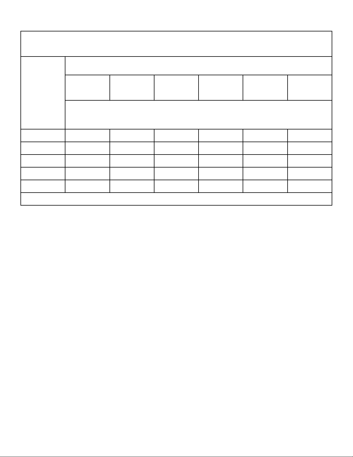
Gas Pipe Size Required for 1000 Btu Natural Gas (Standard Conditions) at Upstream Pressure — 2 ± 0.4 psi
[138 ± 27.6 mbar, 13.7 ± 2.74 kPa] Water Column Pressure
GasAp-
pliances
Total
Btu/hr.
Equivalent Length
25 feet
[7.63 m]
50 feet
[15.25 m]
75 feet
[22.88 m]
100 feet
[30.50 m]
125 feet
[38.13 m]
150 feet
[45.75 m]
Based on 1 psi Pressure Drop for Length Given
Sizes shown in inches [mm]
2,200,000 0.75 [19.05] 1 [25.40] 1 [25.40] 1.25 [31.75] 1.25 [31.75] 1.25 [31.75]
2,400,000 1 [25.40] 1 [25.40] 1 [25.40] 1.25 [31.75] 1.25 [31.75] 1.5 [38.10]
2,600,000 1 [25.40] 1 [25.40] 1.25 [31.75] 1.25 [31.75] 1.25 [31.75] 1.5 [38.10]
2,800,000 1 [25.40] 1 [25.40] 1.25 [31.75] 1.25 [31.75] 1.25 [31.75] 1.5 [38.10]
3,000,000 1 [25.40] 1 [25.40] 1.25 [31.75] 1.25 [31.75] 1.25 [31.75] 1.5 [38.10]
For L.P. Gas, correct the total Btu/hr by multiplying it by 0.6. The answer is the equivalent Btu on the above chart.
Table 6
High Altitude Orifice Sizing
For proper operation at altitudes above 2000 feet [610 meters],
the gas orifice size must be reduced to ensure complete combus-
tion. Refer to Table 7 .
For CE models, consult local gas supplier.
Gas Requirements
©
Copyright, Alliance Laundry Systems LLC -
DO NOT COPY or TRANSMIT
48 Part No. 70458101ENR11
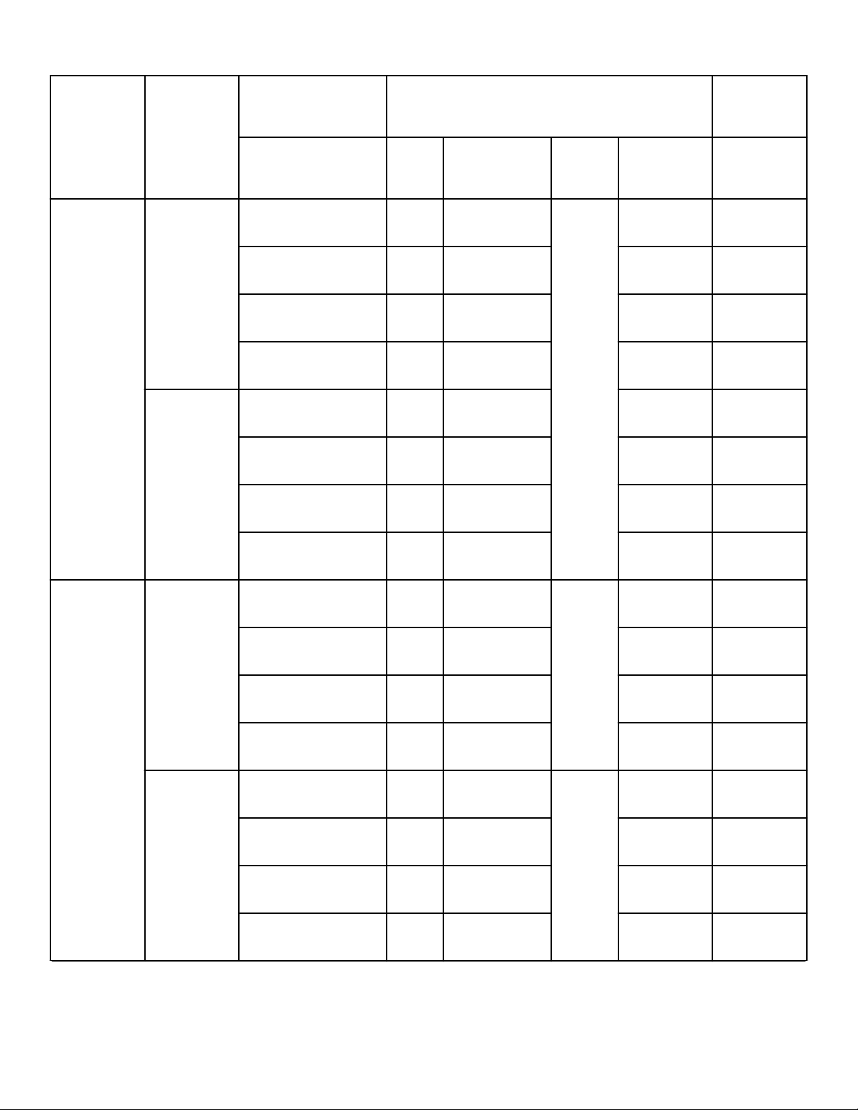
Model Gas
Altitude Orifice
New
Rate
feet [m] No.
inches
[mm]
Qua
ntity Part No.
Btu/hr.*
[Mj/hr.]
120L/N Natural Gas 2,001 – 4,000 [610 –
1,220]
18 0.1695 [4.3] 3 M402988 248,400
[262]
4,001 – 6,000 [1,221 –
1,830]
19 0.1660 [4.2] M402995 226,800
[239]
6,001 – 8,000 [1,831 –
2,440]
21 0.1590 [4] M402992 205,200
[216]
8,001 – 10,000 [2,441
– 3,050]
24 0.1520 [3.9] M402980 183,600
[194]
L.P. Gas 2,001 – 4,000 [610 –
1,220]
38 0.1015 [2.6] M411376 248,400
[262]
4,001 – 6,000 [1,221 –
1,830]
40 0.0980 [2.5] M406361 226,800
[239]
6,001 – 8,000 [1,831 –
2,440]
42 0.0935 [2.4] M403017 205,200
[216]
8,001 – 10,000 [2,441
– 3,050]
43 0.0890 [2.3] M406184 183,600
[194]
170L/N Natural Gas 2,001 – 4,000 [610 –
1,220]
16 0.1770 [4.5] 4 M411373 363,400
[383]
4,001 – 6,000 [1,221 –
1,830]
11/64 0.1719 [4.4] 44249901 331,800
[350]
6,001 – 8,000 [1,831 –
2,440]
19 0.1660 [4.2] M402995 300,200
[317]
8,001 – 10,000 [2,441
– 3,050]
22 0.1570 [4] M402996 268,600
[283]
L.P. Gas 2,001 – 4,000 [610 –
1,220 ]
1/8 0.1250 [3.2] 3 M402489 363,400
[383]
4,001 – 6,000 [1,221 –
1,830]
31 0.1200 [3] M401017 331,800
[350]
6,001 – 8,000 [1,831 –
2,440]
32 0.1160 [2.9] M402444 300,200
[317]
8,001 – 10,000 [2,441
– 3,050]
34 0.1110 [2.8] M411512 268,600
[283]
Table 7 continues...
Gas Requirements
©
Copyright, Alliance Laundry Systems LLC -
DO NOT COPY or TRANSMIT
49 Part No. 70458101ENR11
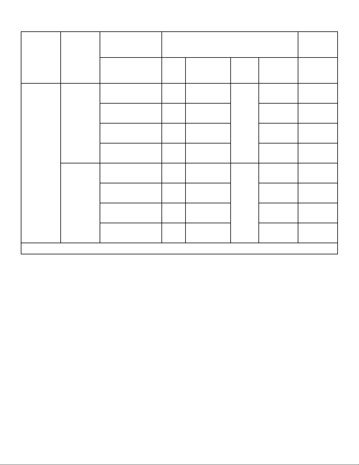
Model Gas
Altitude Orifice
New
Rate
feet [m] No.
inches
[mm]
Qua
ntity Part No.
Btu/hr.*
[Mj/hr.]
200L/N Natural Gas 2,001 – 4,000 [610 –
1,220]
12 0.1890 [4.8] 4 M411372 391,000
[413]
4,001 – 6,000 [1,221 –
1,830]
14 0.1820 [4.6] M411371 357,000
[377]
6,001 – 8,000 [1,831 –
2,440]
17 0.1730 [4.4] M411374 323,000
[341]
8,001 – 10,000 [2,441
– 3,050]
19 0.1660 [4.2] M402995 289,000
[305]
L.P. Gas 2,001 – 4,000 [610 –
1,220]
30 0.1285 [—] 3 M401021 391,000
[413]
4,001 – 6,000 [1,221 –
1,830]
1/8 0.1250 [3.2] M402489 357,000
[377]
6,001 – 8,000 [1,831 –
2,440]
31 0.1200 [3] M401017 323,000
[341]
8,001 – 10,000 [2,441
– 3,050]
33 0.1130 [2.9] M401022 289,000
[305]
*Btu/hr. derate of 4% per 1,000 ft. [305 m] of altitude.
Table 7
Gas Requirements
©
Copyright, Alliance Laundry Systems LLC -
DO NOT COPY or TRANSMIT
50 Part No. 70458101ENR11
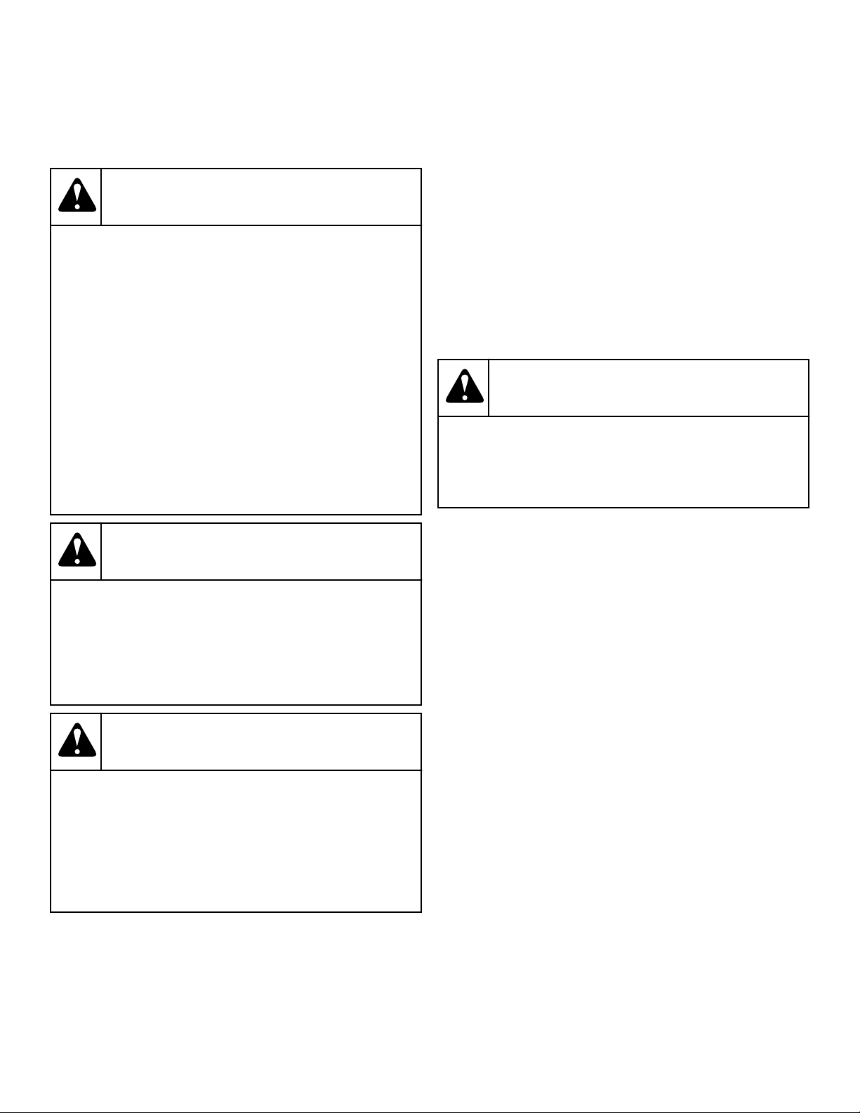
Electrical Requirements
Electrical Requirements
WARNING
To reduce the risk of electric shock, fire, explosion,
serious injury or death:
• Disconnect electric power to the tumble dryer be-
fore servicing.
• Close gas shut-off valve to gas tumble dryer be-
fore servicing.
• Close steam valve to steam tumble dryer before
servicing.
• Never start the tumble dryer with any guards/
panels removed.
• Whenever ground wires are removed during serv-
icing, these ground wires must be reconnected to
ensure that the tumble dryer is properly ground-
ed.
W002R1
WARNING
To reduce the risk of fire and electric shock, check
with a qualified service person for proper grounding
procedures. Improper connection of the equipment
grounding conductor may result in a risk of electric
shock.
W068R1
WARNING
To reduce the risk of fire and electric shock, if elec-
trical supply is coming from a three phase service,
DO NOT connect a “High Leg” or “Stinger Leg” to a
single phase machine. On a three phase machine, if
there is a “High Leg” or “Stinger Leg” it should be
connected to L3.
W069
IMPORTANT: Electrical connections must be made by a
qualified electrician using data on serial plate, installa-
tion manuals and wiring diagram provided with ma-
chine and according to local codes. Install a circuit
breaker as close to the tumble dryer as possible. If
more than one tumble dryer is being installed, a circuit
breaker must be provided for each.
NOTE: Connect machine to an individual branch circuit
not shared with lighting or other equipment.
NOTE: 3 Phase Machines Only - Do not use fuses to
avoid the possibility of “single phasing” and causing
premature failure of the motors.
WARNING
In case of servicing (or putting the tumble dryer out
of order), disconnect the tumble dryer from the main
supply by switching off the circuit breaker.
W796
Wiring Diagram
The wiring diagram is located in the junction or contactor box.
The wiring diagram part number is in the lower portion of the
electrical data on the serial plate.
Grounding Instructions
NOTE: To ensure protection against shock, this tumble
dryer MUST be electrically grounded in accordance
with the local codes, or in the absence of local codes,
with the latest edition of the National Electrical Code
ANSI/NFPA No. 70. In Canada the electrical connec-
tions are to be made in accordance with CSA C22.1 lat-
est edition Canadian Electrical Code, or local codes.
Electrical work should be done by a qualified electri-
cian.
This tumble dryer must be grounded. In the event of malfunction
or breakdown, grounding will reduce the risk of electric shock by
providing a path of least resistance for electric current. This tum-
ble dryer must be connected to a grounded metal, permanent wir-
ing system; or an equipment grounding conductor must be run
with the circuit conductors and connected to the appropriate
ground location.
• Metal conduit and/or BX cable is not considered ground.
• Connecting the Neutral from the electrical service box to the
tumble dryer ground screw does not constitute a ground.
Electrical Requirements
©
Copyright, Alliance Laundry Systems LLC -
DO NOT COPY or TRANSMIT
51 Part No. 70458101ENR11
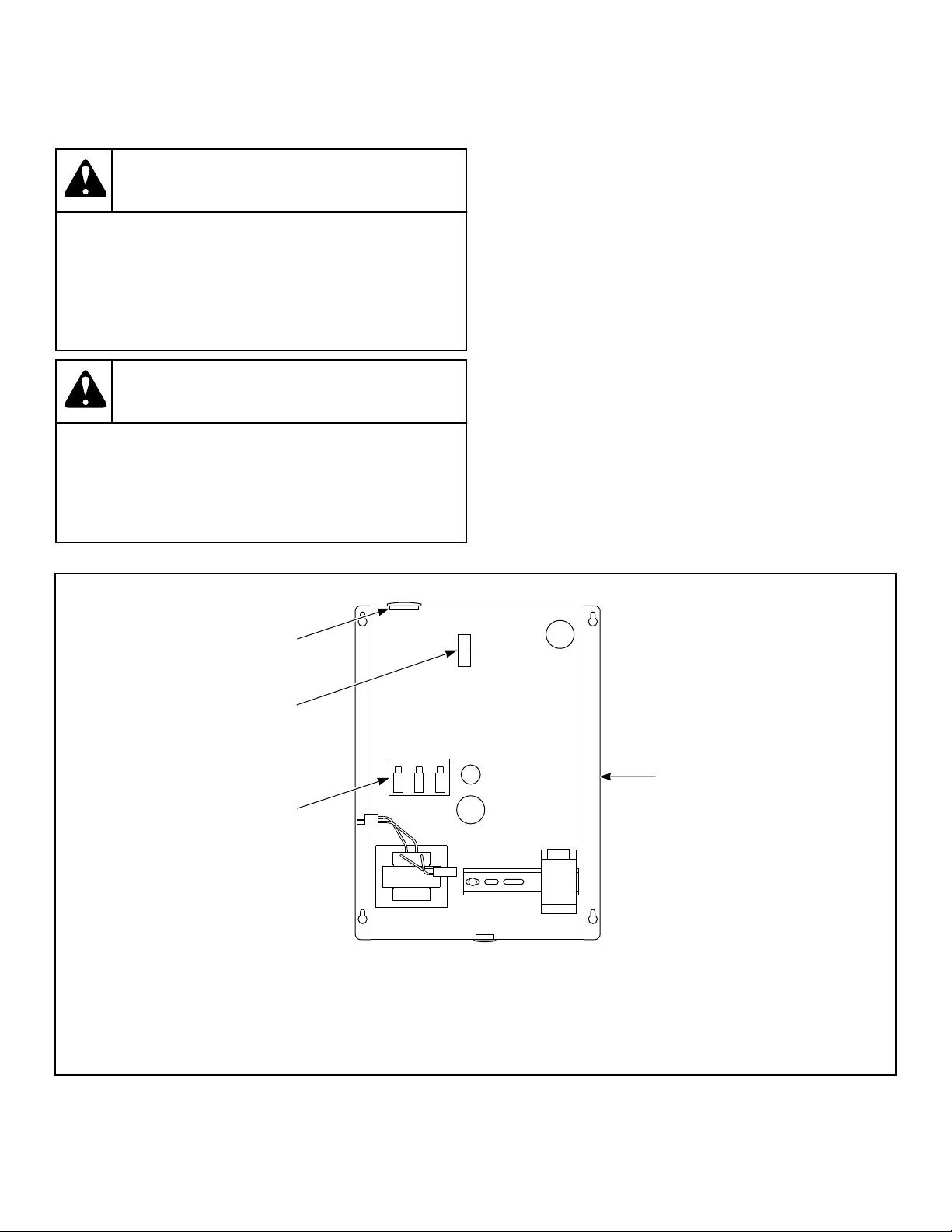
• A dedicated ground conduit (wire) must be connected be-
tween the electrical service box ground bar and tumble dryer
ground screw.
WARNING
To reduce the risk of electrical shock, de-energize
the electrical circuit being connected to the tumble
dryer before making any electrical connections. All
electrical connections should be made by a qualified
electrician. Never attempt to connect a live circuit.
W409R1
CAUTION
Label all wires prior to disconnection when servicing
controls. Wiring errors can cause improper and dan-
gerous operation. Verify proper operation after serv-
icing.
W071
For CE Models Only
All models are factory-equipped with an emergency stop button
on the front panel.
NOTE: Activation of the emergency stop switch stops
all machine control circuit functions, but DOES NOT re-
move all electrical power from machine.
Service/Ground Location
Ground and Terminal Block Locations for Non-CE Gas and Steam Models
TMB2269N_SVG
1
2
3
4
1. Junction Box
2. Terminal Block
3. Earth/Ground
4. Electrical Service
Figure 17
Electrical Requirements
©
Copyright, Alliance Laundry Systems LLC -
DO NOT COPY or TRANSMIT
52 Part No. 70458101ENR11
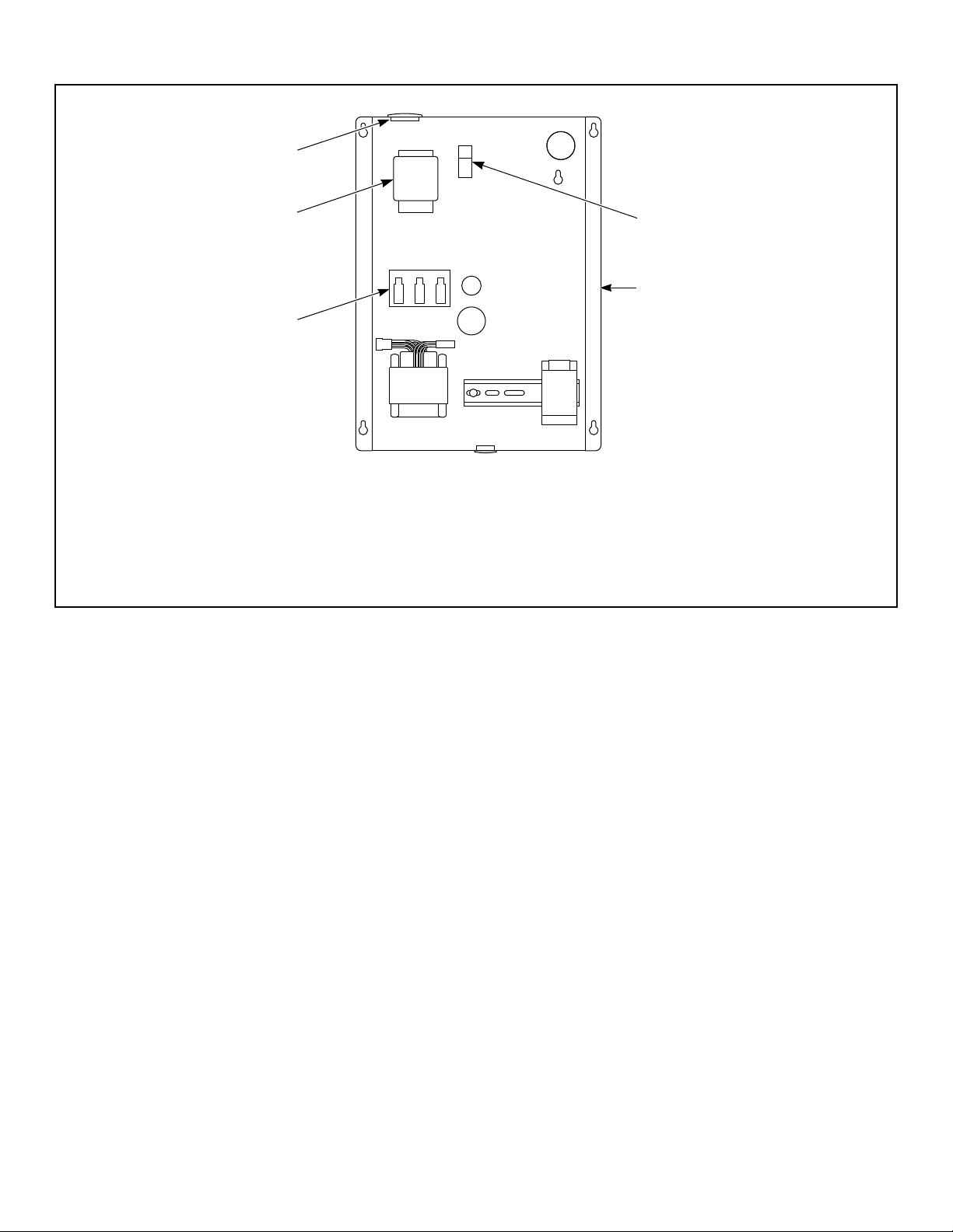
Ground and Terminal Block Locations for CE Gas and Steam Models
TMB2247N_SVG
2
1
3
4
5
1. Earth/Ground
2. Junction Box
3. Terminal Block
4. Power Disconnect (Models Through 7/31/11)
5. Electrical Service
Figure 18
Electrical Requirements
©
Copyright, Alliance Laundry Systems LLC -
DO NOT COPY or TRANSMIT
53 Part No. 70458101ENR11
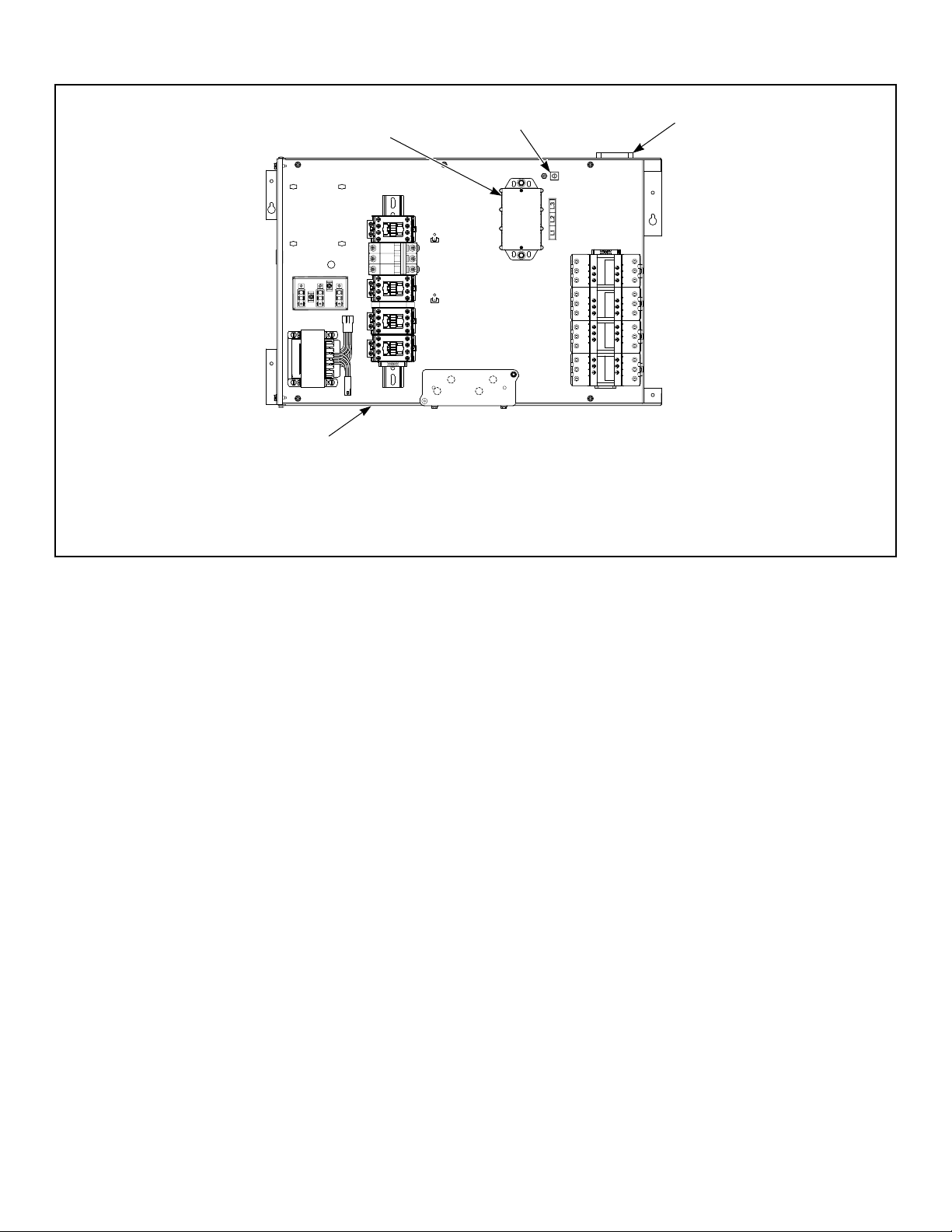
Ground and Terminal Block Locations for Electric Models
TMB2337N_SVG
1
4
2
3
1. Terminal Block
2. Earth/Ground
3. Electrical Service
4. Contactor Box
Figure 19
To Connect Electrical Service To The
Tumble Dryer
NOTE: The wiring diagram is located in the junction
box.
1. Install a circuit breaker as close to the tumble dryer as possi-
ble. If more than one tumble dryer is being installed, a discon-
nect switch or circuit breaker should be provided for each.
This will make it possible to disconnect each tumble dryer for
maintenance purposes.
2. Connect the conduit-encased leads to the disconnect switch,
or circuit breaker. Connect the wire leads to the appropriate
labeled terminal on the terminal block. The ground wire must
be connected to the ground connection as shown in Figure
17 , Figure 18 or Figure 19 .
3. Check the electrical service phase sequence (three phase on-
ly). If one of the power leads is a “high leg,” connect it to lead
L3 in the tumble dryer. The cylinder must rotate clockwise
and the fan must rotate counterclockwise (as viewed from the
front of the tumble dryer – with selector switch in non-reverse
position). If not, interchange leads L1 and L2 in the tumble
dryer connection box.
Jumper Configuration Instructions
Changing the transformer configuration jumper is required, PRI-
OR TO SUPPLYING POWER TO THE MACHINE, if any of the
following apply:
IMPORTANT: Failure to install the proper configuration
jumper may result in damage to sensitive electronic
controls and may void warranty.
• You have 400 – 415 Volt service and are connecting a model
rated for 380 Volt operation.
Ferrite Ring Installation
Gas and Steam Models with RM Control Suffix Only (Models Through 7/31/11)
The ferrite ring provided in the literature packet must be installed over the power leads during connection of electrical service. The
ferrite protects the sensitive electronic controls from destructive electrical disturbances which may be present on power lines to the
machine. Failure to properly install the ferrite ring may result in damage to the electronic controls and will void control warranty.
To install: 1. Immediately after connection of power leads and before ap-
plying power to machine, locate each of the incoming service
leads including ground.
Electrical Requirements
©
Copyright, Alliance Laundry Systems LLC -
DO NOT COPY or TRANSMIT
54 Part No. 70458101ENR11

2. Snap the ferrite ring closed over all the service leads inside of
the contactor box as shown. It is important that the ferrite ring
be installed inside the contactor box. Refer to Figure 20 . Do
not install the ferrite outside of the box or other area. Make
sure that service leads are in the center of the ferrite before
closing the ring so as not to pinch or damage leads.
Electrical Requirements
©
Copyright, Alliance Laundry Systems LLC -
DO NOT COPY or TRANSMIT
55 Part No. 70458101ENR11
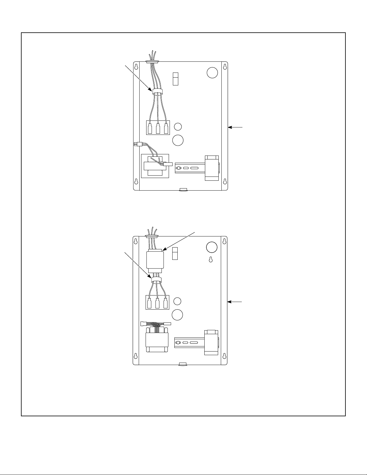
Non-CE Models
TMB2270N_SVG
2
1
CE Models
TMB2271N_SVG
2
1
3
1. Ferrite Ring
2. Junction Box
3. Models Through 7/31/11
Figure 20
Electrical Requirements
©
Copyright, Alliance Laundry Systems LLC -
DO NOT COPY or TRANSMIT
56 Part No. 70458101ENR11
Electrical Specifications
NOTE: Minimum wire sizes are obtained from Canadian
Electrical Code and are intended for use as a guideline
only. Electrical connections should be made only by a
qualified electrical contractor in accordance with all ap-
plicable local and national requirements.
NOTE: Electrical specifications below are subject to
change without notice. Always refer to product serial
plate for most current specifications of product being
installed.
NOTE: Use copper conductors only.
NOTE: Connect to individual branch circuit.
NOTE: 3 Phase Only – Each tumble dryer must be con-
nected to its own individual branch circuit breaker, not
fuses, to avoid the possibility of “single phasing” and
causing premature failure of the motor(s).
120 Series Gas and Steam Tumble Dryer Models
Serial Plate Rat-
ing
Terminal Block
Connections Re-
quired
Rated Current*
(amps) Breaker Rating
Recommended
Wire Size AWG
[mm²]
200-208/240V/
60Hz/3ph
L1,L2,L3 and ground 7.7 15A - 3 pole 14 [2.5]
230V/50Hz/3ph L1,L2,L3 and ground 7.3 15A - 3 pole 14 [2.5]
380V/50 or 60Hz/3ph L1,L2,L3 and ground 4.1 10A - 3 pole 14 [2.5]
400-415V/50Hz/3ph L1,L2,L3 and ground 3.8 10A - 3 pole 14 [2.5]
440V/60Hz/3ph L1,L2,L3 and ground 3.8 10A - 3 pole 14 [2.5]
460-480V/60Hz/3ph L1,L2,L3 and ground 3.9 10A - 3 pole 14 [2.5]
* Current ratings vary slightly depending on model; refer to serial plate.
120 Series Electric Tumble Dryer Models
Serial Plate Rat-
ing
Terminal Block
Connections Re-
quired
Rated Current*
(amps) Breaker Rating
Recommended
Wire Size AWG
[mm²]
240V/60Hz/3ph L1,L2,L3 and ground 152 175A - 3 pole 3/0 [95]
380V/50 or 60Hz/3ph L1,L2,L3 and ground 94.5 125A - 3 pole 1 [35]
400-415V/50Hz/3ph L1,L2,L3 and ground 87 125A - 3 pole 1 [35]
480V/60Hz/3ph L1,L2,L3 and ground 76.1 100A - 3 pole 3 [26.2]
* Current ratings vary slightly depending on model; refer to serial plate.
Electrical Requirements
©
Copyright, Alliance Laundry Systems LLC -
DO NOT COPY or TRANSMIT
57 Part No. 70458101ENR11
170 Series Tumble Dryer Models
Serial Plate Rat-
ing
Terminal Block
Connections Re-
quired
Rated Current*
(amps) Breaker Rating
Recommended
Wire Size AWG
[mm²]
200-208/240V/
60Hz/3ph
L1,L2,L3 and ground 13.5 20A - 3 pole 12 [4]
380V/50 or 60Hz/3ph L1,L2,L3 and ground 6.9 15A - 3 pole 14 [2.5]
400-415V/50Hz/3ph L1,L2,L3 and ground 6.9 15A - 3 pole 14 [2.5]
440V/60Hz/3ph L1,L2,L3 and ground 6.4 15A - 3 pole 14 [2.5]
460-480V/60Hz/3ph L1,L2,L3 and ground 6.7 15A - 3 pole 14 [2.5]
* Current ratings vary slightly depending on model; refer to serial plate.
200 Series Tumble Dryer Models
Serial Plate Rat-
ing
Terminal Block
Connections Re-
quired
Rated Current*
(amps) Breaker Rating
Recommended
Wire Size AWG
[mm²]
200-208/240V/
60Hz/3ph
L1, L2, L3 and ground 14 20A - 3 pole 12 [ 4]
380V/50Hz/3ph L1, L2, L3 and ground 8 15A - 3 pole 14 [2.5]
400-415V/50Hz/3ph L1, L2, L3 and ground 8 15A - 3 pole 14 [2.5]
440V/60Hz/3ph L1, L2, L3 and ground 7 15A - 3 pole 14 [2.5]
460-480V/60Hz/3ph L1, L2, L3 and ground 7 15A - 3 pole 14 [2.5]
* Current ratings vary slightly depending on model; refer to serial plate.
Electrical Requirements
©
Copyright, Alliance Laundry Systems LLC -
DO NOT COPY or TRANSMIT
58 Part No. 70458101ENR11

Steam Requirements
Steam Requirements
NOTE: Machines require a constant 80 to 100 psig [5.3
to 6.9 bar] steam service for optimum operation. The
maximum allowable steam pressure is 125 psig [8.6
bar]. In no case may the pressure exceed the above
value.
Obtain specific steam service pipe sizes from steam system sup-
plier or a qualified steam fitter.
• Refer to Figure 21 and Figure 22 for proper steam pipe con-
figurations.
• To prevent condensate draining from headers to tumble dryer,
piping should have a minimum 12 inch [305 mm] rise above
respective header. Do not make steam connection to header
with a horizontal or downward facing tee or elbow.
• Whenever possible, horizontal runs of steam lines must drain,
by gravity, to respective steam header. Water pockets, or an
improperly drained steam header will provide wet steam,
causing improper operation of tumble dryer. If pockets or im-
proper drainage cannot be eliminated, install a bypass trap to
drain condensate from the low point in the steam header to the
return.
• In both steam supply and steam return line, it is recommended
that each have a pipe union and shut-off valve. This will ena-
ble you to disconnect the steam connections and service the
tumble dryer while your laundry facility is in operation.
• Connect the steam solenoid valve to the related steam coil in-
let connection with nipples, flex hoses, unions and tees.
• Strainers may require cleaning due to materials from hoses or
pipes.
• Install vacuum breaker (optional), bucket trap with built-in
strainer and check valve. For successful operation of tumble
dryer, install trap 18 inches [457 mm] below coil and as near
to the tumble dryer as possible. Inspect trap carefully for inlet
and outlet markings and install according to trap manufactur-
er's instructions. If steam is gravity returned to boiler, omit
trap but install vacuum breaker and check valve in return line
near tumble dryer. Gravity return requires entire return
plumbing be below steam coil outlets.
• Install union and shut-off valve in return line and make final
pipe connections to return header.
NOTE: To prevent water hammering, route return
lines below outlets of steam coils.
NOTE: CE machines are shipped with BSPT adapt-
ers in the lint compartment.
Steam Requirements
©
Copyright, Alliance Laundry Systems LLC -
DO NOT COPY or TRANSMIT
59 Part No. 70458101ENR11
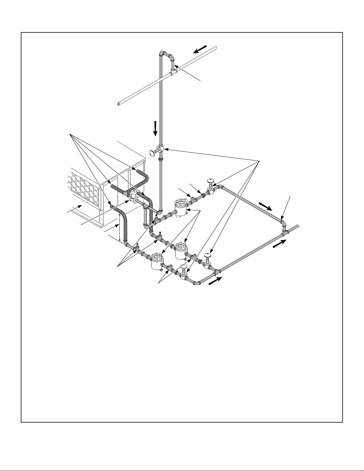
120 Series Tumble Dryers
TMB2014N_SVG
7
6
6
3
5
12
13
1
2
11
8
10
9
4
NOTE: Refer to Table 8 for sizing of steam lines. Piping must also be sized accordingly for length of runs and
number of elbows.
1. Supply
2. 12 in. [305 mm] Riser
3. Shut-Off Valve
4. Condensate Return Line from Supply Line
5. Return
6. Check Valve
7. Vacuum Breaker (Optional)
8. 18 in. [457 mm] Drop
9. Solenoid Valve (Supplied with machine)
10. Steam Bonnet
11. Flexible Line
12. Union
13. Trap with Built-In Strainer
Figure 21
Steam Requirements
©
Copyright, Alliance Laundry Systems LLC -
DO NOT COPY or TRANSMIT
60 Part No. 70458101ENR11

Steam Pressure PSI [bar] Minimum Supply Pipe Diameter
Steam Trap Size* Pounds Con-
densate/Hour [Kilograms Con-
densate/Hour]
80-100 [5.3-6.9] 1 in. NPT 345 [156]
*Based on 6.9 bar.
Table 8
Steam Requirements
©
Copyright, Alliance Laundry Systems LLC -
DO NOT COPY or TRANSMIT
61 Part No. 70458101ENR11
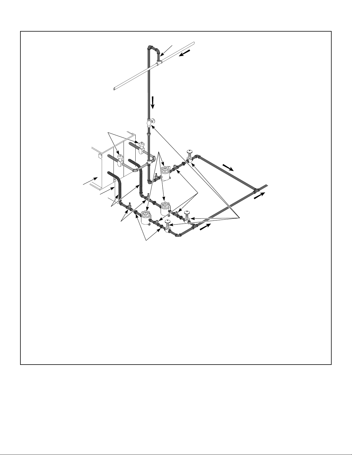
170 and 200 Series Tumble Dryers
TMB2024N_SVG
11
12
7
8
6
2
3
10
4
1
5
9
NOTE: Refer to Table 9 for sizing of steam lines. Piping must also be sized accordingly for length of runs and
number of elbows.
1. Risers 12 in. [305 mm]
2. Shut-Off Valve
3. Check Valve
4. Vacuum Breaker (optional)
5. Condensate Return Line from Supply Line
6. Drop 18 in. [457 mm]
7. Steam Bonnet
8. Solenoid Valve (Supplied with machine)
9. Union
10. Trap with Built-In Strainer
11. Return
12. Supply
Figure 22
Steam Requirements
©
Copyright, Alliance Laundry Systems LLC -
DO NOT COPY or TRANSMIT
62 Part No. 70458101ENR11
Steam Pressure PSI [ bar]
Minimum Supply Pipe Diameter
Steam Trap Size*
Pounds Condensate/Hour [Kilo-
grams Condensate/Hour]
80-100 [5.3-6.9] 1-1/4 in. NPT 517 [235]
* Based on 6.9 bar.
Table 9
Piping Recommendations
• Trap each steam coil individually. Always keep the trap clean
and in good working condition.
• When tumble dryer is on the end of a line of equipment, ex-
tend header at least 4 feet [1.2 m] beyond tumble dryer. Install
shut-off valve, union, check valve and bypass trap at end of
line. If gravity return to boiler, omit trap.
• Insulate steam supply and return lines for safety of operator
and safety while servicing tumble dryer.
WARNING
All system components must have a 125 psig [8.6
bar] working pressure. Shut-off valves must be in-
stalled upstream of the steam solenoid valve and
downstream of each steam trap so components can
be isolated for maintenance or emergency purposes.
All components (solenoid valve, traps) must be sup-
ported to minimize loads on the tumbler steam coil
connections.
W701
Installing Steam Trap and Making Con-
densate Return Connections
The steam trap must be installed and the coil outlet connections
must be connected to the condensate return lines. The following
steps outline the procedure for installing the steam trap and con-
necting the condensate return lines. Refer to Figure 21 and Fig-
ure 22 for typical installations.
1. Use flexible lines between steam inlet solenoid and steam
coils, as well as outlet between steam coil and traps.
2. If necessary, install a strainer at the end of each flexible hose.
3. Install a steam trap to each strainer.
IMPORTANT: Steam trap must be installed a mini-
mum of 18 inches [457 mm] below the steam coil
outlet connections.
4. Install a shut-off valve to each steam trap.
5. Connect to the condensate return lines.
6. For steam solenoid valve wiring connections, refer to Wiring
Diagram supplied with tumble dryer.
Thermal Oil Prep
It is the responsibility of the customer to install appropriate coil
and heating system for thermal oil prep models. The manufactur-
er is not responsible for the performance or safety of the custom-
er installed thermal oil system. To ensure proper operation, refer
to the Specifications and Dimensions section for the Btu input of
equivalent steam models. Thermal oil systems that do not deliver
appropriate Btus will dry slower. For solenoid valve wiring con-
nections, refer to the Wiring Diagram supplied with tumble dryer.
Steam Requirements
©
Copyright, Alliance Laundry Systems LLC -
DO NOT COPY or TRANSMIT
63 Part No. 70458101ENR11
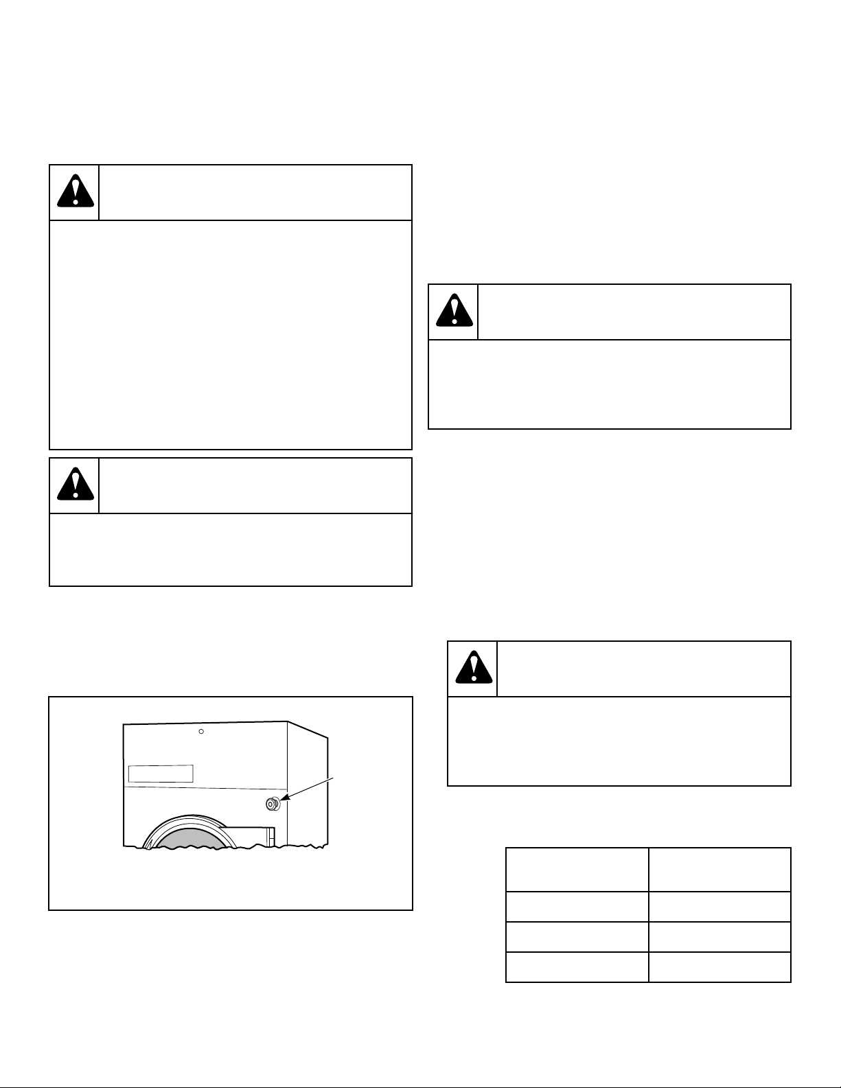
Operating Instructions
Operating Instructions
WARNING
To reduce the risk of fire:
• DO NOT DRY articles containing foam rubber or
similarly textured rubberlike materials.
• DO NOT DRY plastics, anything containing wax or
chemicals such as mops and cleaning cloths, or
anything dry-cleaned at home with a dry-cleaning
solvent.
• DO NOT TUMBLE fiberglass curtains and draper-
ies unless the label says it can be done. If they
are dried, wipe out the cylinder with a damp cloth
to remove particles of fiberglass.
W076
WARNING
To reduce the risk of serious injury, allow cylinder to
stop before cleaning lint screen.
W412
Emergency Stop Button On CE Models
All CE approved tumble dryers are factory equipped with an
emergency stop button located on the front panel. Refer to Figure
23 .
TMB1666N_SVG
1
1.
Emergency Stop Button
Figure 23
To operate emergency stop button:
• Press red emergency stop button to stop all action.
• To restart machine, pull red emergency stop button out and
press START pad or button.
NOTE: Activation of the emergency stop button
stops all machine control circuit functions, but
DOES NOT remove all electrical power from ma-
chine.
Operating Instructions
WARNING
To reduce the risk of fire, electric shock, or injury to
persons, read the IMPORTANT SAFETY INSTRUC-
TIONS before operating this appliance.
W727
IMPORTANT: This appliance shall not be used to dry
off solvents or dry cleaning fluids.
1. Clean Lint Screen/Compartment
a. Remove any accumulated lint from the lint screen and
compartment.
b. Close panel tightly against tumble dryer frame and lock
panel securely, if applicable.
IMPORTANT: Clean lint screen and lint compartment
daily. Failure to clean the lint screen daily will result
in higher than normal temperatures that may dam-
age laundry.
WARNING
To reduce the risk of fire and risk of lint collecting
in exhaust duct, do not operate tumbler without
lint filter in place.
W772
2. Load Laundry
a. Open loading door and load cylinder with laundry. Maxi-
mum drying load is:
Model Pound [Kg]
120 120 [55]
170 170 [77]
200 200 [90]
DO NOT OVERLOAD.
Operating Instructions
©
Copyright, Alliance Laundry Systems LLC -
DO NOT COPY or TRANSMIT
64 Part No. 70458101ENR11
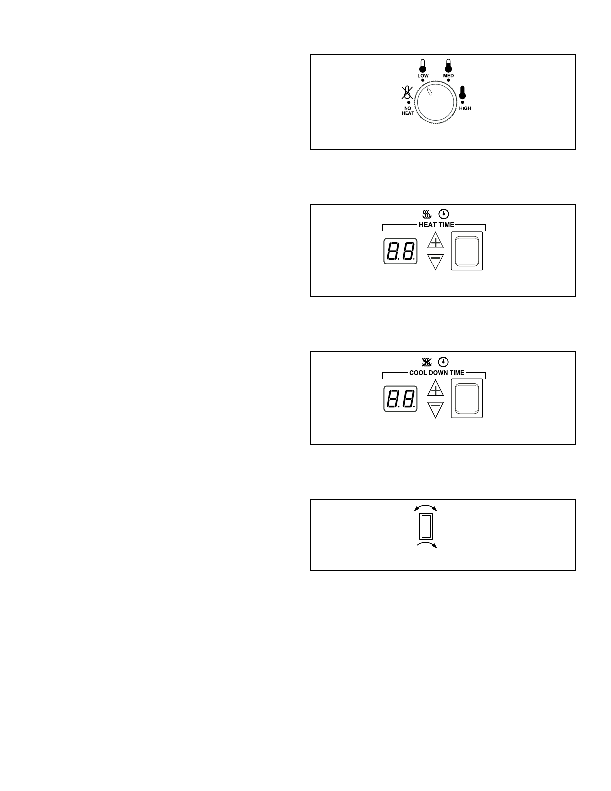
NOTE: Overloading causes slow drying and wrin-
kling.
b. Close loading door. Tumble dryer will not operate with the
door open.
3. Determine Control Type and Temperature Setting
a. Refer to the various controls and follow the instructions
for the appropriate control type.
b. The type of fabric being dried will determine the tempera-
ture setting. Consult the fabric care label or fabric manu-
facturer to determine proper temperature setting.
IMPORTANT: Always follow the fabric care instruc-
tions supplied by the garment manufacturer.
4. Remove Laundry
a. When the cycle is complete, open door and remove the
laundry.
Reversing Operation
Tumble dryers with the reversing option prevent the tangling of
large pieces of laundry and minimize wrinkling. These tumble
dryers are equipped with a second motor and additional controls
which reverse the rotation direction of the cylinder.
Some models may have a switch or touchpad in the control panel
area so the operator can select the reversing or nonreversing oper-
ation. In nonreversing mode, the cylinder will always turn clock-
wise (as viewed from the front of the tumble dryer). If the cylin-
der is turning counterclockwise when switched to nonreversing, it
will continue for a few seconds and then start up in the proper di-
rection. Refer to Programming Manual for more information on
reversing.
IMPORTANT: After any electrical maintenance is done,
make sure that the blower motor is turning counter-
clockwise as viewed from the front. Then set the re-
verse control switch to “nonreversing” and note that
the cylinder turns constantly clockwise as viewed from
the front of the tumble dryer. If not, interchange L1 and
L2 service leads to the reverse drive motor.
Control Instructions
Dual Digital Timer Control
RQ Control Suffix
1. Select HIGH, MED, LOW or NO HEAT by turning the tem-
perature knob.
HIGH
Temperature 190°F [88°C]
MED
Temperature 170°F [ 77°C]
LOW
Temperature 120°F [49°C]
TMB2147N_SVG
Figure 24
2. Set the HEAT TIME for the number of minutes (from 0 - 60)
desired.
TMB2148N_SVG
Figure 25
3. Set the COOL DOWN TIME for the number of minutes
(from 0 - 15) desired.
TMB2149N_SVG
Figure 26
4. Select reversing or nonreversing cylinder rotation setting, if
applicable.
TMB2145N_SVG
Figure 27
5. Press and release START button to start tumble dryer. Display
will show minutes remaining before end of cycle.
Operating Instructions
©
Copyright, Alliance Laundry Systems LLC -
DO NOT COPY or TRANSMIT
65 Part No. 70458101ENR11
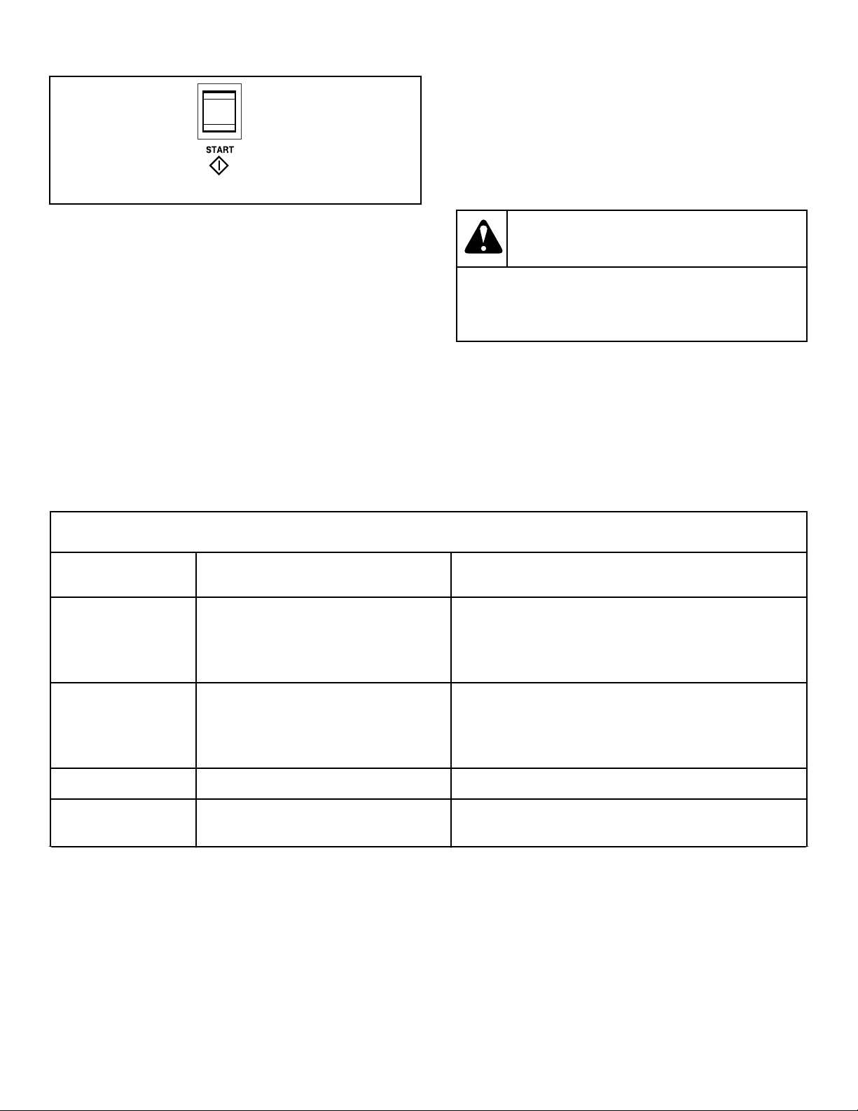
TMB2150N_SVG
Figure 28
NOTE: One touch drying is available for repetitive
loads. If the START button is pressed while the ma-
chine is in Idle Mode, when the display is dark, the
tumble dryer will repeat the last drying cycle. If the
cycle time is adjusted before the cycle is started,
the time displayed when the start button was press-
ed will be used for future cycles.
IMPORTANT: To stop the tumble dryer at any time
during the cycle, OPEN DOOR. If the loading door or
lint panel door is opened during the cycle, the heat-
ing system will shut off and the motor will stop. To
restart the cycle, both doors must be closed and the
START button must be pressed in.
If the load cools to 90°F [32°C] before cool down time expires,
the control will flash “Lr” (load ready) in the heat time display. If
the door is not opened, the tumble dryer completes the selected
cool down time. If the door is opened after reaching “Lr” temper-
ature, the cycle will be terminated.
NOTE: If display shows an error code, refer to Error
Codes section.
6. When the cycle is complete, open door and remove the laun-
dry.
WARNING
To prevent the risk of fire, remove laundry imme-
diately in case of power failure.
W779
NOTE: This machine includes an anti-wrinkle/ ex-
tended tumble feature. After the drying cycle is
complete, the cylinder will tumble without heat ev-
ery few minutes. The intermittent tumbling will con-
tinue for one hour or until the door is opened. Anti-
wrinkle feature will tumble the load without heat for
30 seconds every 2 minutes for 1 hour OR until the
loading door is opened.
Error Codes
Display Definition Corrective Action
OP Open thermistor error • Check thermistor. Replace if inoperative.
• Check wiring diagram between control and thermistor.
Refer to wiring diagram for proper wiring.
• Check control. Replace if inoperative.
SH Shorted thermistor error • Check thermistor. Replace if inoperative.
• Check wiring between control and thermistor. Refer to
wiring diagram for proper wiring.
• Check control. Replace if inoperative.
AF - 1 Airflow switch closed when cycle started • Check airflow switch. Replace if inoperative.
AF - 2 Airflow switch failed to close after cycle
started
• Check airflow switch. Replace if inoperative.
Table 10 continues...
Operating Instructions
©
Copyright, Alliance Laundry Systems LLC -
DO NOT COPY or TRANSMIT
66 Part No. 70458101ENR11
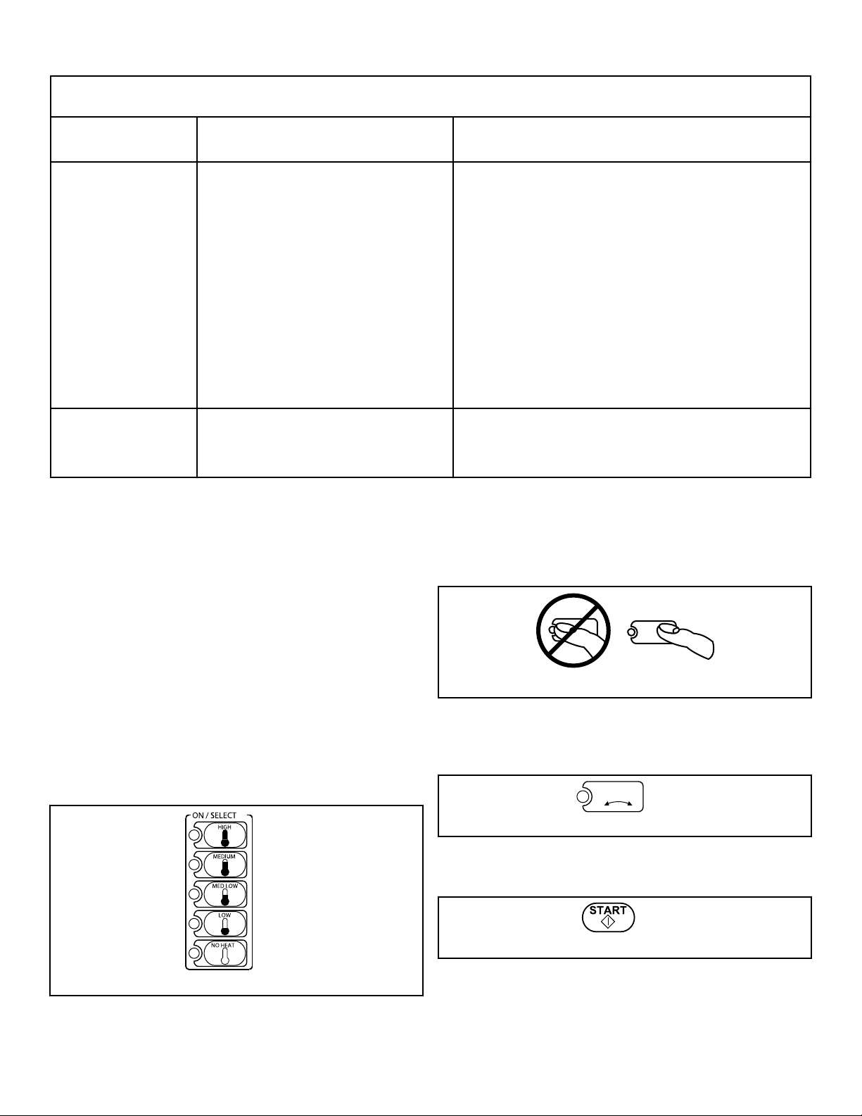
Error Codes
Display Definition Corrective Action
AF (Flashing) Bouncing Airflow Switch • Cycling power will not clear error. Start machine and al-
low it to terminate normally. To quickly advance cycle,
set HEAT TIME to 0 and COOL DOWN TIME to 1, then
press START (control may flash "Lr"). Once machine has
cycled, identify and correct problem.
• Check airflow switch to ensure that it is properly aligned
and securely mounted in the mounting bracket.
• Make sure airflow switch can open and close freely.
• Check installation and make sure there is adequate air-
flow.
• Make sure exhaust is not blocked.
• Clean the lint screen.
• Replace airflow switch if inoperative.
AF (Solid) Airflow Switch Closed when Resuming
Cycle
• Allow up to 20 seconds for this condition to clear.
• Check if airflow switch opens at end of cycle.
• Replace airflow switch if inoperative.
Table 10
Electronic OPL Micro Control
RM Control Suffix
1. To use an Automatic Cycle, press an ON/SELECT pad. Select
HIGH, MEDIUM, MED LOW, LOW or NO HEAT for items
that should not be dried with heat. A light to the left of the se-
lected pad lights up.
HIGH
Temperature 180°F [82°C]
MEDIUM
Temperature 160°F [ 71°C]
MED LOW
Temperature 140°F [60°C]
LOW
Temperature 120°F [49°C]
To use a Time Dry or Custom Cycle, refer to the Programming
Manual.
TMB1483N_SVG
Figure 29
NOTE: Do not press directly on lights or the center
of pad. For proper selection, press on pad slightly
to the right of center. Refer to Figure 30 .
TMB806N_SVG
Figure 30
2. Select REVERSING or NONREVERSING cylinder rotation
setting.
TMB1486N_SVG
REVERSING
Figure 31
3. Press START pad to start tumble dryer.
TMB1485N_SVG
Figure 32
Operating Instructions
©
Copyright, Alliance Laundry Systems LLC -
DO NOT COPY or TRANSMIT
67 Part No. 70458101ENR11
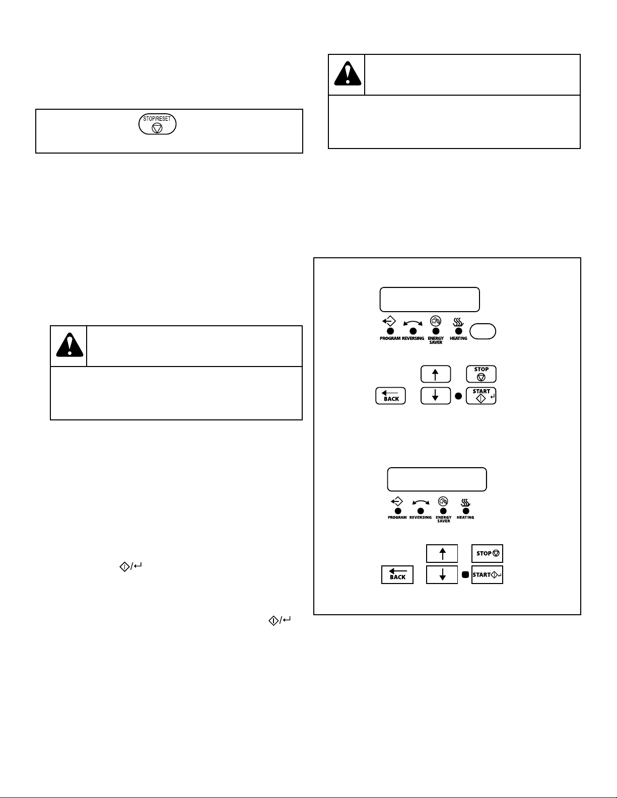
NOTE: All pads can be pressed in any sequence
without damaging control or tumble dryer. To stop
the tumble dryer at any time, open the door or press
STOP/RESET.
TMB1484N_SVG
Figure 33
NOTE: The window display will flash. Press STOP/
RESET twice (within three seconds) to end the cycle
and reset the control to idle status. To restart the
tumble dryer, CLOSE door and press START pad.
IMPORTANT: If the loading door or lint panel door is
opened during the cycle, the heating system will
shut off and the motor will stop. To restart the cycle,
both doors must be closed and START pad must be
pressed.
4. When the cycle is complete, open door and remove the laun-
dry.
WARNING
To prevent the risk of fire, remove laundry imme-
diately in case of power failure.
W779
NOTE: This machine includes an anti-wrinkle/ ex-
tended tumble feature. After the drying cycle is
complete, the cylinder will tumble without heat ev-
ery few minutes. The intermittent tumbling will con-
tinue for one hour or until the door is opened.
LED OPL Control
RE Control Suffix
1. Press the Up or Down keypad to change cycles.
To customize a cycle, refer to the Programming Manual.
2.
Press START ( ) to start selected cycle.
IMPORTANT: If the loading door or lint panel door is
opened during the cycle, the heating system will
shut off and the motor will stop. To restart the cycle,
both doors must be closed and the START ( )
pad must be pressed.
3. When the cycle is complete, open door and remove laundry.
WARNING
To prevent the risk of fire, remove laundry imme-
diately in case of power failure.
W779
NOTE: This machine includes an anti-wrinkle/
extended tumble feature. After the drying cycle is
complete, the cylinder will tumble without heat ev-
ery few minutes. The intermittent tumbling will con-
tinue for one hour or until the door is opened. After
an hour the machine enters delayed tumble and will
tumble for two minutes every hour for up to 18
hours or until the door is opened.
S Models
TMB1345R_SVG
H Models
TMB1346R_SVG
Figure 34
Operating Instructions
©
Copyright, Alliance Laundry Systems LLC -
DO NOT COPY or TRANSMIT
68 Part No. 70458101ENR11
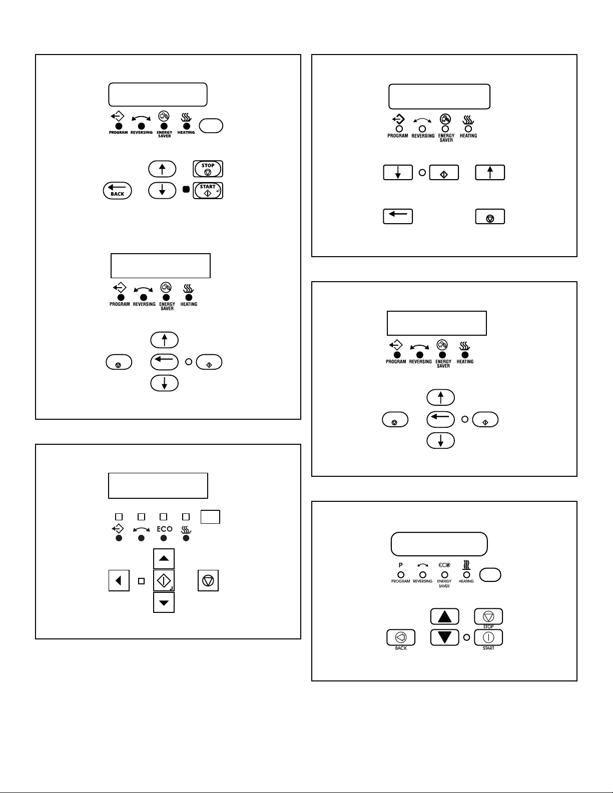
U Models
TMB1371R_SVG
Y Models
TMB2370N_SVG
START
STOP
BACK
Figure 35
C, D, and I Models
TMB1375R_SVG
Figure 36
P Models Through 5/31/15
START
BACK
STOP
TMB2369N_SVG
Figure 37
L Models Through 5/31/15; N Models
TMB2370N_SVG
START
STOP
BACK
Figure 38
L and P Models Starting 6/1/15
TMB1464R_SVG
Figure 39
UniLinc Control
Operating Instructions
©
Copyright, Alliance Laundry Systems LLC -
DO NOT COPY or TRANSMIT
69 Part No. 70458101ENR11
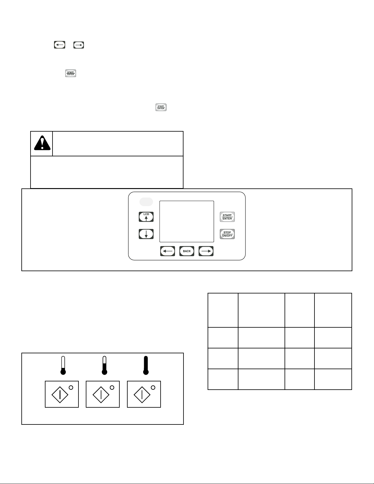
RU Control Suffix
1.
Press the or keypad to change cycles. The center
highlighted position is the selected cycle.
To customize a cycle, refer to the Programming Manual.
2.
Press START to start selected cycle.
IMPORTANT: If the loading door or lint panel door is
opened during the cycle, the heating system will
shut off and the motor will stop. To restart the cycle,
both doors must be closed and the START
pad
must be pressed.
3. When the cycle is complete, open door and remove laundry.
WARNING
To prevent the risk of fire, remove laundry imme-
diately in case of power failure.
W779
NOTE: This machine includes an anti-wrinkle/
extended tumble feature. After the drying cycle is
complete, the cylinder will tumble without heat ev-
ery few minutes. The intermittent tumbling will con-
tinue for one hour or until the door is opened. After
an hour the machine enters delayed tumble and will
tumble for two minutes every hour for up to 18
hours or until the door is opened.
TMB1276C_SVG
Figure 40
DX4 OPL Control
R3 Control Suffix
1. Open door and fill drum with clothes.
2. Press and release one of the cycle buttons to select a cycle and
start the tumble dryer. Refer to Table 11 .
To use a custom cycle, refer to the Programming Manual.
TMB2266N_SVG
Figure 41
Tempera-
ture
Dry-
ing
Time
Cool
Down
Time
Left But-
ton
104°F [40°C] 30 min. 2 min.
Middle
Button
140°F [60°C] 30 min. 2 min.
Right
Button
176°F [80°C] 35 min. 2 min.
Table 11
IMPORTANT: To stop the tumble dryer at any time
during the cycle, OPEN DOOR. To restart the tumble
dryer, CLOSE door and press START button.
3. When the cycle is complete, open door and remove the laun-
dry.
Operating Instructions
©
Copyright, Alliance Laundry Systems LLC -
DO NOT COPY or TRANSMIT
70 Part No. 70458101ENR11
WARNING
To prevent the risk of fire, remove laundry imme-
diately in case of power failure.
W779
Diagnostic Microprocessor Control
General Operation
The Diagnostic Microprocessor Control (DMP) is designed to
manage the drying and cooling cycles of the tumble dryer. The
controller is also programmed from the factory with five different
default programs as described below. The operator has the flexi-
bility to select the time for the drying and the cool down cycles
and the drying temperature. The operator may also select either
reversing or nonreversing basket action only if the tumble dryer
is equipped for reversing. The operator may also reprogram the
default programs. See Programming.
Default
Pro-
grams
Dry
Tim
e
(Mi
n.)
Cool
Time
(Min.)
Temp.
Set
Point
Re-
ver
sin
g
1 – Towels 40 5 185º/195ºF
[85º/91ºC]
No
2 – Sheets 30 5 165ºF [74ºC] Yes
3 – Misc-1 30 5 150ºF [66ºC] No
4 – Misc-2 25 5 135ºF [57ºC] Yes
5 – Extra
Dry
5 2 150ºF [66ºC] No
NOTE: If an altered program is determined to be cor-
rupted, the default program settings will be used.
Features
• Drying time: 0-60 minutes
• Cooling time: 2-60 minutes
• LED display of cycle time, set temperature, and actual tem-
perature
• Thermistor controlled temperature
• Safety tumble cycle
• Buzzer for end of cycle, audible alarm
• Reversing/Nonreversing selection
• Five user programmable programs
• RPM display – when equipped with rotational sensor only
• Monitors the lint door switch operation
• Monitors the thermistor for operation
The minimum drying time is 0 minutes, and the minimum cool-
ing time is 2 minutes. The maximum drying or cooling time is 60
minutes. The drying temperature may be set from 100ºF [38ºC] to
185º/195ºF [85º/91ºC]. The drying time, cooling time, or temper-
ature may be modified during an operating cycle.
If it is necessary to reset the drying and cooling times for the cur-
rent cycle, press STOP once to stop the tumble dryer. Press STOP
again to cancel the cycle.
If it is necessary to change programs during a current cycle, press
STOP once to stop the tumble dryer and press STOP again to
cancel the current cycle.
DMP OPL Models
RD Control Suffix
Operating Instructions
©
Copyright, Alliance Laundry Systems LLC -
DO NOT COPY or TRANSMIT
71 Part No. 70458101ENR11
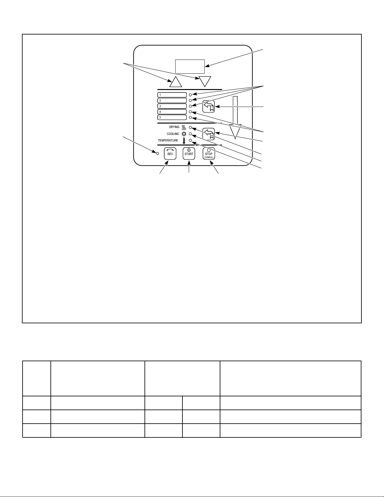
Description of the OPL Control Panel
TMB1956N_SVG
6
8
7
8
213
4
5
10
11
12
9
1. START. Starts or resumes the current program or cycle.
2. STOP. Temporarily halts the current cycle or cancels the current program.
3. Reversing/Nonreversing (REV). Changes the selection between reversing and nonreversing cylinder action.
4. Reversing LED. Illuminated when set for reversing.
5. Up/Down Arrows. Increases or decreases the value in the display. In conjunction with the DISPLAY button, these buttons are
used to adjust the drying time, cooling time, temperature, clockwise time, dwell time, counter-clockwise time, and minutes per
coin (Coin only).
6. Display. Displays the drying time, cooling time, drying temperature and diagnostic codes.
7. Program Select. This button toggles through the five user programmable programs. Holding this button will save a program, as
indicated in Programming.
8. User Program LEDs. Illumination shows which user program is currently being displayed.
9. Display Select. Toggles the display between the drying time, cooling time, and temperature settings. Pressing the Display button
for 3 seconds allows the user to display the drying cycle temperature.
10. DRYING LED. Illuminated when in the drying cycle.
11. COOLING LED. Illuminated when in the cooling cycle, or when the display is currently showing the time for the cooling cycle.
12. TEMPERATURE LED. Illuminated when the display is showing the temperature setting.
Figure 42
The DMP has an 8 position DIP switch bank that is accessible
from the back of the control board. By switching these DIP
switches, it is possible for the operator to customize the display
and some of the operating features of the tumble dryer.
Fun
ctio
n OPL Coin
1 Tumble dryer Type OFF ON OPL=Off; Coin=On
2 Temperature Units OFF OFF ºF=Off; ºC=On
3 Local/Remote Reversing ON ON Local=On; Remote=Off
Table continues...
Operating Instructions
©
Copyright, Alliance Laundry Systems LLC -
DO NOT COPY or TRANSMIT
72 Part No. 70458101ENR11
Fun
ctio
n OPL Coin
4 Empty ON ON Always ON
5 Empty ON ON Always ON
6 Buzzer Timer ON ON 5 Sec=Off; Continuous=On
7 Safety Tumble (OPL) or Coin
Count/Pay (Coin)
ON OFF #1 #7 DIP SWITCH
OFF ON SAFETY TUMBLE
OFF OFF NO SAFETY TUM-
BLE
ON ON COIN COUNT
ON OFF PAY
8 Programming OFF OFF Disable=Off; Enable=On
DIP Switch Functions Explained
1. Tumble dryer Type: This DIP switch selects the type of tum-
ble dryer, i.e., OPL or Coin.
2. Temperature Units: Selects ºF or ºC for the temperature dis-
play. Factory setting is for ºF.
3. Local/Remote Reversing: Preset at the factory; usually for lo-
cal reversing. Remote reversing for use with Reversing Timer
Board only.
4. Empty: Preset at the factory; always ON.
5. Empty: Preset at the factory; always ON.
6. Buzzer Timer: This DIP switch determines the length of time
that the end of cycle buzzer will remain on. “OFF” indicates
that the buzzer will sound for 5 seconds when the drying cy-
cle is completed. “ON” indicates that the buzzer will sound
continuously until the STOP button is pressed or the loading
door is opened.
7. Safety Tumble (OPL) or Coin count/Pay (Coin): If DIP
switch #1 is set for OPL, then DIP switch #7 in the ON posi-
tion enables the safety tumble. If DIP switch #1 is set for
Coin, then DIP switch #7 in the ON position enables the dis-
play of the coin count. DIP switch #7 in the OFF position ena-
bles the display of “PAy”, to indicate that coins are needed to
run the tumble dryer.
8. Programming: This switch enables or disables the program-
ming feature and should normally be in the OFF position.
Ignition Control Operation and Trouble-
shooting for Models Starting 3/11/13
WARNING
70458601 and 70458701 controls cannot be serviced
by the user. If any control failures are detected, the
controls must be replaced by qualified service per-
sonnel. Risk of explosion or fire can result if the con-
trol module has been opened or with any attempts to
repair it and the warranty is void.
W818
Before troubleshooting the system, check the following items:
- Verify all mechanical and electrical connections are secure and
tight.
- Verify all system wiring is correct.
- Verify there is a proper system ground. The igniter, flame sensor
and igniter module must share a common ground with the burner.
Nuisance shutdowns are often caused by a poor or erratic ground.
- Verify that the system is powered and that the control is calling
for heat.
- If the control proceeds to an error code on the red diagnostic
LED, troubleshoot per the Fault conditions table below:
Operating Instructions
©
Copyright, Alliance Laundry Systems LLC -
DO NOT COPY or TRANSMIT
73 Part No. 70458101ENR11
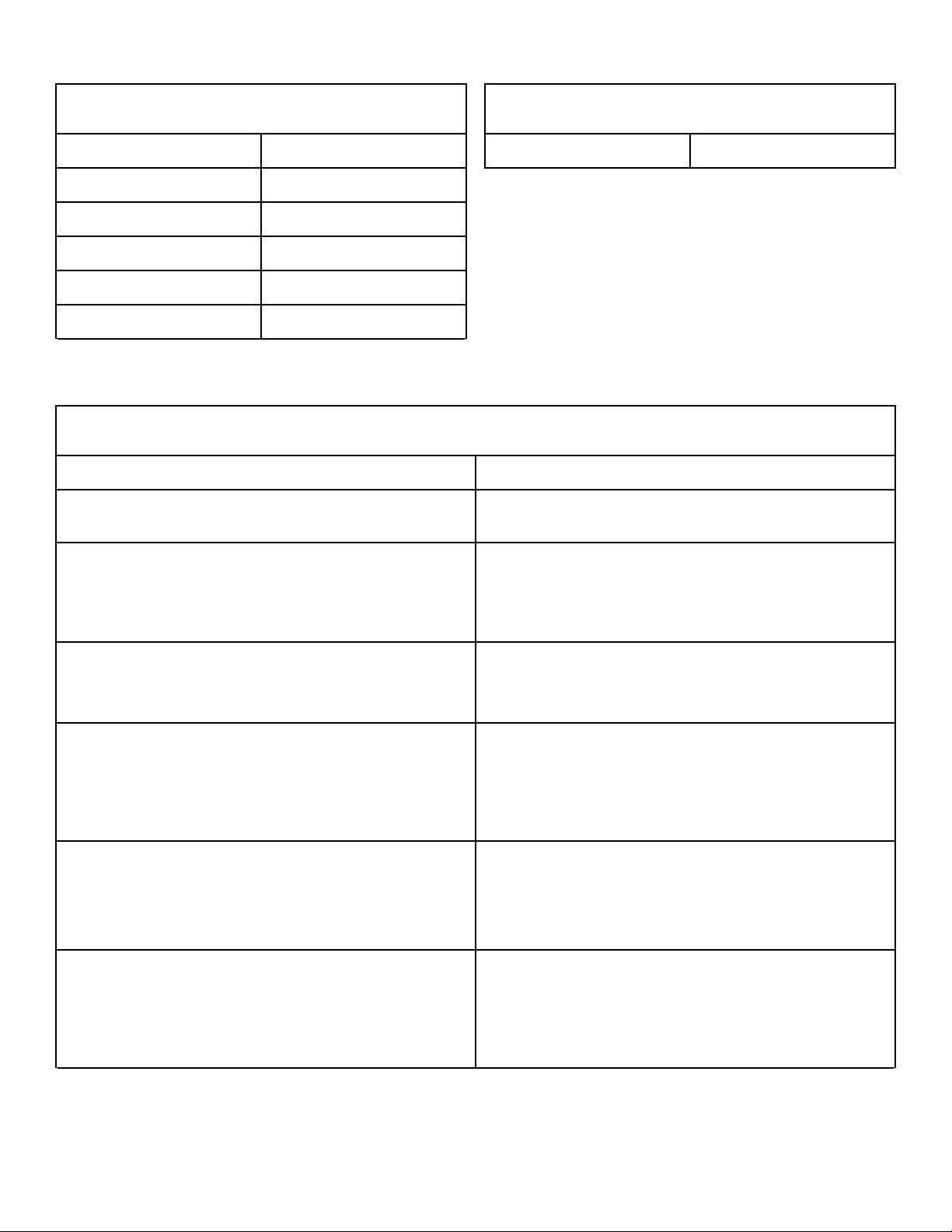
Fault Conditions
LED Indication Fault Mode
Off Normal Operation
1 Flash At Power Up
2 Flashes Flame Without Call For Heat
3 Flashes Ignition Lockout
4 Flashes (70458701 only) Manual Reset Error
Table continues...
Fault Conditions
Steady On Internal Control Failure
NOTE: The LED will flash on for 1/4 second, then off for
1/4 second during a fault condition. The pause between
fault codes is 3 seconds.
Internal Control Failure
If the control detects an error in its software or hardware, all out-
puts are turned off and the red LED displays a steady ON condi-
tion. If this condition persists after an attempt to restart, then the
control must be replaced.
Troubleshooting
Troubleshooting Guide
Symptom Probable Cause
Control in Lockout Mode (70458701 Control Only) Manual reset of the control is needed. Reset by pushing red
lockout button or use front end control.
Control does not start, green LED is off 1. 24 VAC present between 24V and ground on 70458701 only.
If not, see machine schematic.
2. 24 VAC present between TH and ground. If not, see machine
schematic.
Thermostat on, no spark or valve 1. Cable connects to control and electrode. Voltage present at
gas valve.
2. Bad control. Check red LED for steady on or flashing codes.
Valve on, no spark during TFI 1. Shorted electrode.
2. Spark gap not correct. Set to .094-.156 inch.
3. High voltage cable is faulty or has a poor connection.
4. Control failure.
Spark on, no flame 1. Is gas on?
2. 24 VAC at gas valve.
3. Bad control. Check voltage between gas valve terminal MV
and GND on control.
Flame okay during TFI, no flame sense after TFI 1. Check electrode position and cleanliness.
2. Check high voltage wire.
3. Poor ground at burner.
4. Poor flame, check flame current.
Table continues...
Operating Instructions
©
Copyright, Alliance Laundry Systems LLC -
DO NOT COPY or TRANSMIT
74 Part No. 70458101ENR11
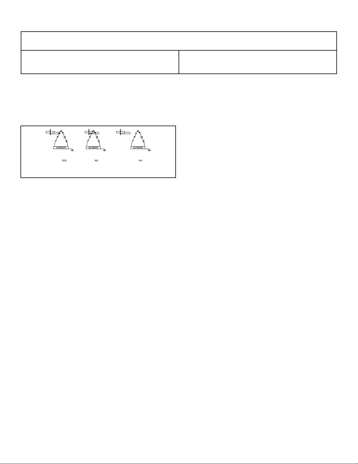
Troubleshooting Guide
Reset failure 1. Reset switch was pressed too long. Try to reset again.
2. Reset switch is shorted. Replace switch.
Proper Electrode Location
Proper location of the electrode assembly is important for optimal
system performance. The electrode assembly should be located
so that the tips are inside the flame envelope and about 1/2 inch
[1.2 cm] above the base of the flame. Refer to Figure 43 .
TMB2317K_SVG
Figure 43
Flame Current Measurement
Flame current is the current that passes through the flame from
sensor to ground. To measure flame current, connect a True RMS
or analog DC micro-ammeter to the FC+ and the FC- terminals.
The reading should be 1.0 micro-amps DC or higher. If the meter
reads negative or below “0” on the scale, the meter leads are re-
versed. Re-connect leads with proper polarity.
Alternately, a Digital Voltmeter may be used to measure the DC
voltage between the FC+ and FC- terminals. Each micro-amp of
flame current produces 1.0 VDC, so a reading of 2.6 VDC would
equate to 2.6 micro-amps.
A good burner ground that matches the control ground is critical
for reliable flame sensing.
Ignition Control Operation for Non-CE
Models Through 3/10/13
Power Up
When power is applied to the ignition control, the control will be-
gin the ignition sequence within 1 – 3 seconds prepurge waiting
time.
Ignition Sequence
The control begins the ignition sequence after prepurge by pow-
ering the ignitor and opening the gas valve. The ignitor will re-
main on either until a flame is sensed or until a maximum of ten
(10) seconds(10 +0/-4 sec) has elapsed. If a flame is established
and lost during the 10 second period, the ignitor will be powered
up again in an attempt to re-ignite the gas.
If no flame is detected within the ten (10) second ignition se-
quence, the control will terminate power to the gas valves, igni-
tor, and enter lockout within 5 seconds.
Normal Operation
Once a flame has been established, the spark ignitor will stop
sparking and the control will continually monitor all inputs. If the
controller senses a loss of flame after flame is established, the gas
valve will remain energized and sparking will commence within
one second of the flame loss. If flame reattempt fails, lockout will
occur within 11 seconds of initial flame loss.
Termination of Flame
Normal flame termination occurs when the thermostat has been
satisfied, meaning there is no immediate need for more heat. The
thermostat will disconnect power from the ignition control, which
will cause the gas valve to close and the flame to go out. After a
short period of time, not less than 1 second, the thermostat will
cool down and close causing power to be reapplied to the ignition
control. When this occurs, the control must complete the same
prepurge and ignition sequence specified above.
Control Lockout
When the control locks out, the gas valve will be closed and all
requests for heat will be ignored. The lockout mode may only be
discontinued by interrupting power to the control or cycling the
thermostat. After this occurs, the control will restart with its nor-
mal power up and ignition sequence.
Low Voltage Detection
The control will have capability for detection of a low voltage in-
put condition. If input voltage on power up is below 19.0VAC
+0.8VAC/-0.5VAC, the control will disable output to gas valve
control relay. If input voltage rises above 19.8VAC for at least
three (3) seconds, the control will then re-enable function of the
gas valve control relay and ignition sequence may begin. On
powerup, the control function must always be disabled if greater
than 19.8VAC.
Ignition Control Operation for CE Mod-
els Through 3/10/13
Power Up
After 24VAC is applied to the ignition control pins 24V and
GND, the Diagnostic LED on the ignition control will turn or-
ange/yellow. If a fault is detected the ignition control will enter
Operating Instructions
©
Copyright, Alliance Laundry Systems LLC -
DO NOT COPY or TRANSMIT
75 Part No. 70458101ENR11

Lockout Mode. If no faults are detected, the Diagnostic LED will
turn Green and the ignition control will enter Standby Mode.
Standby Mode
While in Standby Mode, the ignition control will continually
monitor the system for faults. Once 24VAC is applied to termi-
nals TH and GND on the control, the ignition control will enter
Start Up Mode.
Start Up Mode
During Start Up Mode, the ignition control will monitor the sys-
tem for faults and begin the ignition sequence. If no faults are
present, the ignition control will begin the ignition sequence by
entering an 18 second waiting period. During this time the Green
LED on the ignition control will switch between Red and Green,
before maintaining a Green color.
After the waiting period, the ignition control will turn on the ig-
niter and gas valve. The igniter will remain on until a flame is
sensed, or up to 10 seconds.
Once a flame has been sensed the ignition control will stop spark-
ing, the gas valve will remain on and ignition control will enter
Run Mode.
If a flame is not sensed, the ignition control will then begin two
additional retrials for ignition. The ignition control will re-enter
the 18 seconds waiting period before the ignition control makes
another attempt at ignition. If the three attempts at ignition fail,
the ignition control will enter Lockout Mode.
Run Mode
While in Run Mode the ignition control leaves the gas valve on,
monitors the flame signal, and leaves the igniter off.
If a flame signal is lost during Run Mode, one additional retrial
for ignition will take place within one second. The ignition con-
trol will restore the spark for approximately 10 seconds. If the ig-
nition re-attempt fails, the ignition control will enter Lockout
Mode.
The ignition control will remain in Run Mode until 24VAC is re-
moved from terminals TH and GND on the control.
Termination of Flame
The flame will go out when power is removed from ignition con-
trol. The ignition control will turn off the gas valve and enter
Standby Mode.
Lockout Mode
When Lockout Mode is entered, the ignition control will remove
power to the gas valve, the igniter will turn off, the Lockout/
Reset Light will turn on, and the Diagnostic LED will display the
appropriate Error Code.
Lockout Manual Reset
Lockout Mode is cleared by pressing an external reset switch for
three seconds. The ignition control will clear all error codes and
enter Standby Mode. During Lockout Manual Reset, the Diag-
nostic LED on the ignition control flashes red and orange, and the
Reset Light remains on until the ignition control is reset. After
the Reset Light turns off, stop pressing the switch. Holding the
reset for three seconds after lockout has been cleared will cause a
fault and result in entering Lockout Mode again.
System Tests
The following system tests are performed during normal opera-
tion. System tests are performed at a minimum of every 24 hours.
Low Voltage Detection
If the voltage between terminals TH and GND on the control is
below 18.75VAC +/- 0.75VAC for more than 3 seconds the igni-
tion control will turn off the gas valve and will not attempt to
spark. The Diagnostic LED will display Error Code 5. The igni-
tion control will not enter Lockout Mode if a low voltage condi-
tion is detected, but will enter Standby Mode and wait for the low
voltage condition to be cleared.
If the voltage between terminals TH and GND on the control ris-
es above 19.75VAC +/- 0.1VAC for at least 3 seconds, the igni-
tion control will then enter Start Up Mode.
Low Voltage Detection test is disabled during Run Mode.
Gas Valve
The ignition control verifies that the gas valve is connected. Fail-
ure of this test results in the ignition control entering Lockout
Mode with the Diagnostic LED displaying Error Code 2.
Flame Probe Tests
The Unexpected Presence of Flame test is performed when no
flame is expected. Failure of this test results in the ignition con-
trol entering Lockout Mode with the Diagnostic LED displaying
Error Code 3.
During the Flame Monitoring test, the flame is checked to ensure
the gas is being burned when the gas valve is on. Failure of this
test will result in the ignition control entering Lockout Mode with
the Diagnostic LED displaying Error Code 3.
Diagnostic LED (DGN LED)/Error Codes
The Diagnostic LED or DGN LED is located by the power con-
nector on the ignition control. Refer to Figure 44 . The Diagnos-
tic LED will indicate the status of the ignition control. Refer to
Table 12 .
LED Color
Description
Orange-Yellow Initialization
Green Standby/Normal Operation
Table 12 continues...
Operating Instructions
©
Copyright, Alliance Laundry Systems LLC -
DO NOT COPY or TRANSMIT
76 Part No. 70458101ENR11
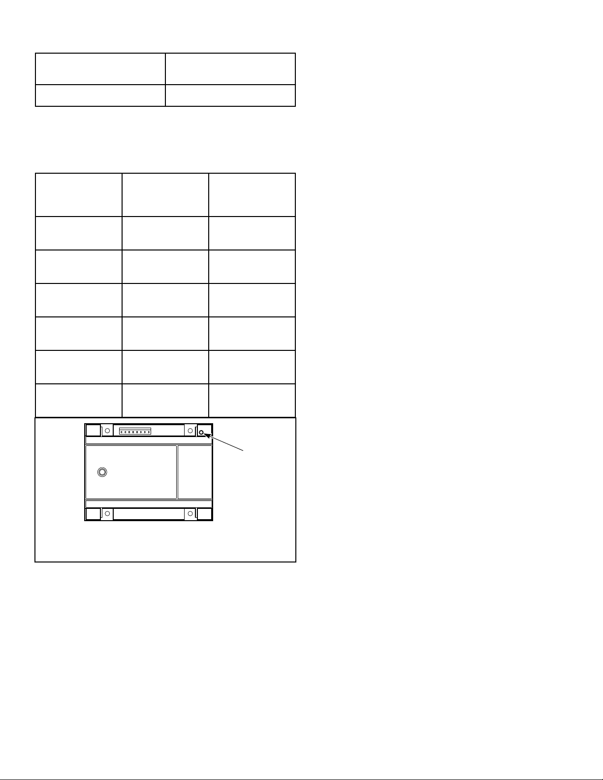
LED Color
Description
Red Fault Indication Code
Table 12
The Diagnostic LED will flash error codes one half second on
and one half second off. Error codes are separated by a one sec-
ond pause before the code is repeated.
Error Code
DGN LED
status Fault Type
1 Red Ignition Control
Internal Failure
2 2 Red Flashes Gas Valve Not
Connected
3 3 Red Flashes Ignition/Flame
Sense Failure
4 4 Red Flashes Reset Switch is
Shorted
5 Slow Red and
Green Flashes
Low Voltage De-
tection
6 Fast Red and Or-
ange Flashes
Ignition Control is
in Reset Delay
TMB2176N_SVG
1
1. Diagnostic (DGN) LED
Figure 44
Operating Instructions
©
Copyright, Alliance Laundry Systems LLC -
DO NOT COPY or TRANSMIT
77 Part No. 70458101ENR11
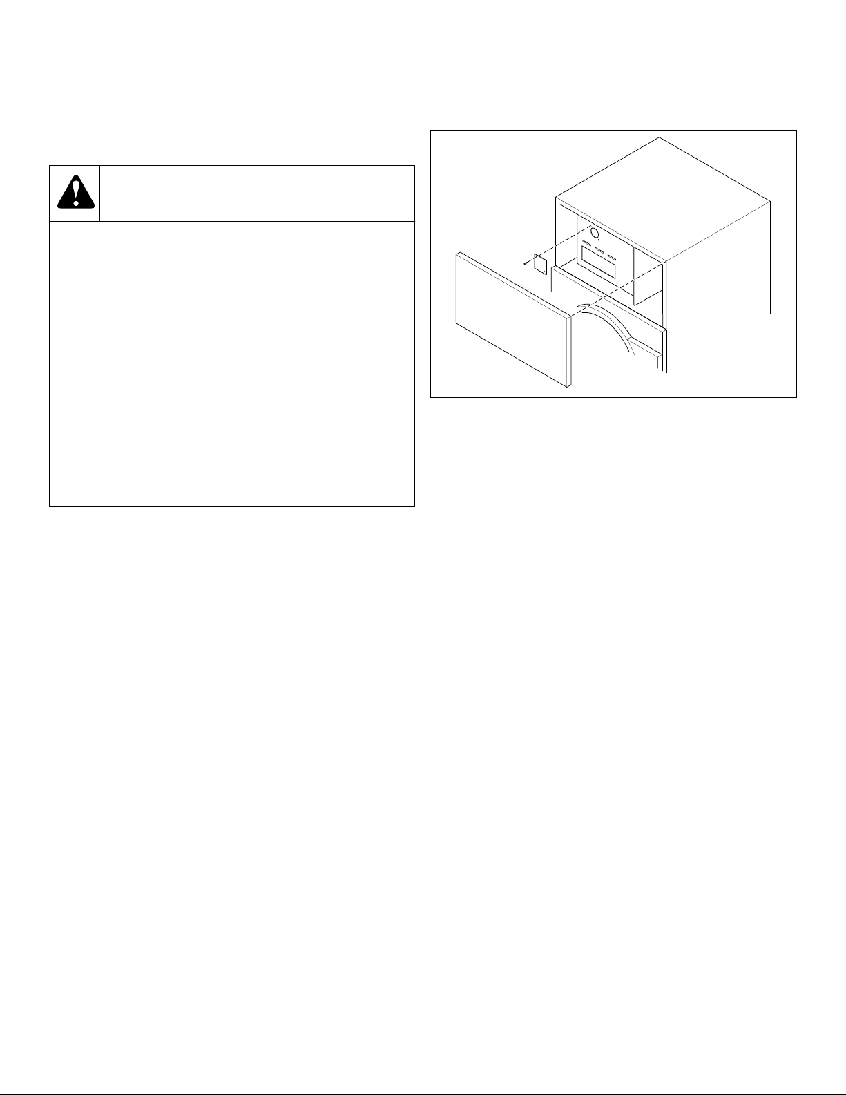
Adjustments
Adjustments
WARNING
To reduce the risk of electric shock, fire, explosion,
serious injury or death:
• Disconnect electric power to the tumble dryer be-
fore servicing.
• Close gas shut-off valve to gas tumble dryer be-
fore servicing.
• Close steam valve to steam tumble dryer before
servicing.
• Never start the tumble dryer with any guards/
panels removed.
• Whenever ground wires are removed during serv-
icing, these ground wires must be reconnected to
ensure that the tumble dryer is properly ground-
ed.
W002R1
Gas Burner Air Shutter
NOTE: Air inlet shutters on the burner must be adjust-
ed so sufficient air is metered into the system for prop-
er combustion and maximum efficiency. Before adjust-
ing the inlet shutters be sure that all lint is removed
from lint compartments and lint screen.
Air shutter adjustments will vary from location to location and
will depend on the vent system, number of units installed, make-
up air and line gas pressure. Opening the shutter increases the
amount of primary air supplied to the burner while closing the
shutter decreases the primary air supply. Adjust air shutter as fol-
lows:
Refer to Figure 45 .
1. Open the access panel and remove the burner inspection hole
plate.
TMB2410N_SVG
Figure 45
2. Start the tumble dryer and check the flame pattern. If the
flame pattern is straight up, insufficient air is flowing through
the tumble dryer. A flame pattern that flares to the right and
left indicates no air is flowing through the tumble dryer. Cor-
rect air and gas mixture is indicated if the flame pattern is pri-
marily blue, with small yellow tips, and bends to the right of
the heater section. Too little air is indicated if the flame if yel-
low, lazy and smokey.
3. To adjust the air shutter, loosen air inlet shutter adjusting
screw.
4. Open or close air shutter as necessary to obtain proper flame
intensity.
5. After air shutter is adjusted for proper flame, tighten air shut-
ter adjusting screw securely.
Adjustments
©
Copyright, Alliance Laundry Systems LLC -
DO NOT COPY or TRANSMIT
78 Part No. 70458101ENR11
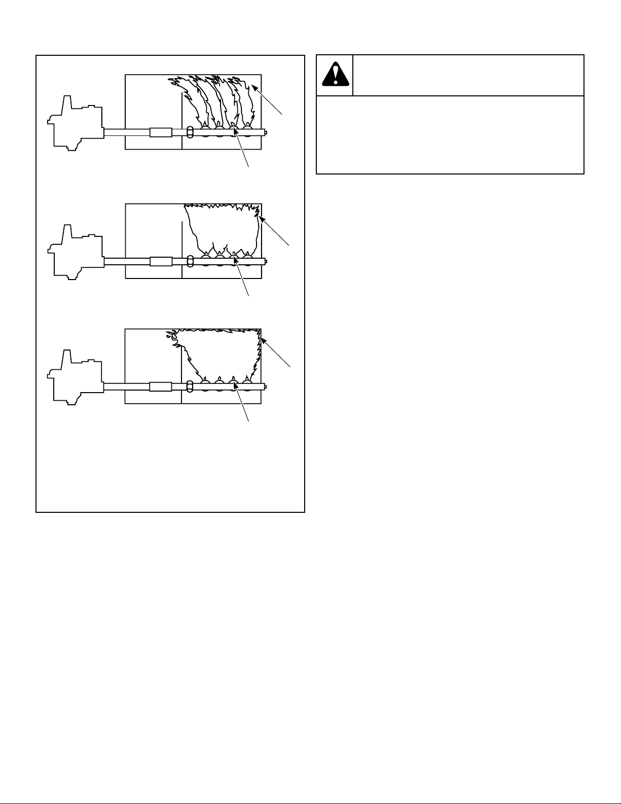
T464I_SVG
1
4
2
4
3
4
1. Proper Airflow
2. Insufficient Airflow
3. No Airflow
4. Air Shutter Adjusting Screw
Figure 46
Airflow Switch
The airflow switch is set at the factory for proper operation. No
adjustment necessary.
The airflow switch operation may be affected by shipping tape
still in place, lack of make-up air, or an obstruction in the exhaust
duct. These should be checked and the required corrective action
taken.
WARNING
The tumble dryer must not be operated if the airflow
switch does not operate properly. Faulty airflow
switch operation may cause an explosive gas mix-
ture to collect in the tumble dryer.
W072R1
IMPORTANT: Airflow switch vane must remain closed
during operation. If it opens and closes during the dry-
ing cycle, this indicates insufficient airflow through the
tumble dryer. If switch remains open, or pops open and
closed during the cycle, the heating system will shut
off. The cylinder and fan will continue to operate even
though the airflow switch is indicating insufficient air-
flow.
NOTE: To properly mount the airflow switch bracket, or
in case of a load not drying, the airflow switch bracket
may need to be checked for proper alignment. Be sure
the locator pins are securely in their respective holes
before tightening the bracket mounting screws. This
will assure proper alignment of the airflow switch arm
in the channel of the airflow switch bracket and prevent
binding of the arm.
Loading Door Switch
Loading door switch is factory preset, no field adjustment is nec-
essary.
Loading Door Catch (120 and 170 Ser-
ies Models)
The door catch must be adjusted to have sufficient tension to hold
loading door closed against force of load tumbling against it.
Proper adjustment is when 7-15 pounds [0.48-1.03 bar] pull is re-
quired to open door.
If adjustment is required, refer to Figure 47 and proceed as fol-
lows:
1. Open door.
2. Loosen acorn nut.
3. Turn door strike screw in or out as required.
4. Tighten acorn nut.
Adjustments
©
Copyright, Alliance Laundry Systems LLC -
DO NOT COPY or TRANSMIT
79 Part No. 70458101ENR11
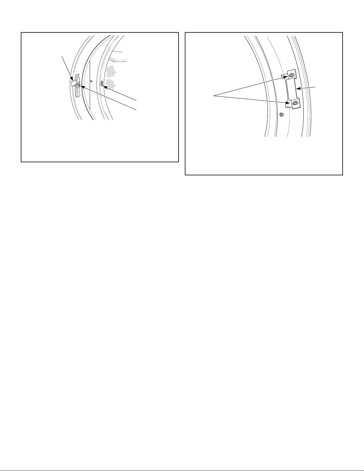
T048I_SVG
2
3
1
1. Door Latch
2. Door Catch
3. Acorn Nut
Figure 47
Loading Door Strike (200 Series Mod-
els)
The loading door strike must be adjusted to have sufficient ten-
sion to hold loading door closed against force of load tumbling
against it. Proper adjustment is when 8-15 pounds [35.6-66.7 N]
pull is required to open door.
If adjustment is required, refer to Figure 48 and proceed as fol-
lows:
1. Open door.
2. Loosen adjustment screws.
3. Position strike for desired magnet engagement.
4. Retighten screws.
TMB2359N_SVG
1
2
1. Door Strike
2. Adjustment Screws
Figure 48
Belt Drive
The drive assemblies consist of motors, belts, eyebolts and a step
pulley.
The pulley diameters are sized to produce a cylinder speed of
37-39 RPM for 120 series models or 29-31 RPM for 170 and 200
series models.
The step pulley assembly is used for speed reduction as well as a
means of adjusting belt tension. The pulley mounting plate is at-
tached to the cabinet. The frame mounting plate has vertically
slotted holes allowing up and down movement of the step pulley
mounting plate for belt adjustment.
Adjust the belt tension as follows:
1. Disconnect electrical power to the tumble dryer before at-
tempting any adjustments to the drive assembly.
2. Loosen pulley mounting plate bolts.
3. Loosen the upper nut on the final drive eyebolt.
4. Rotate the lower nut of the final drive eyebolt clockwise until
proper belt tension is achieved.
5. Rotate upper nut clockwise against the lower nut in order to
lock it into place.
6. Tighten pulley mounting plate bolts. Recheck belt tension.
7. If necessary, adjust the drive motor belt tension eyebolt using
a similar procedure.
8. Adjust blower belt tension on 120 series 50 Hertz tumble dry-
ers and all 170 series tumble dryers using a similar procedure.
NOTE: Proper tensions for new belts are measured
with a Belt Tension Gauge:
Adjustments
©
Copyright, Alliance Laundry Systems LLC -
DO NOT COPY or TRANSMIT
80 Part No. 70458101ENR11
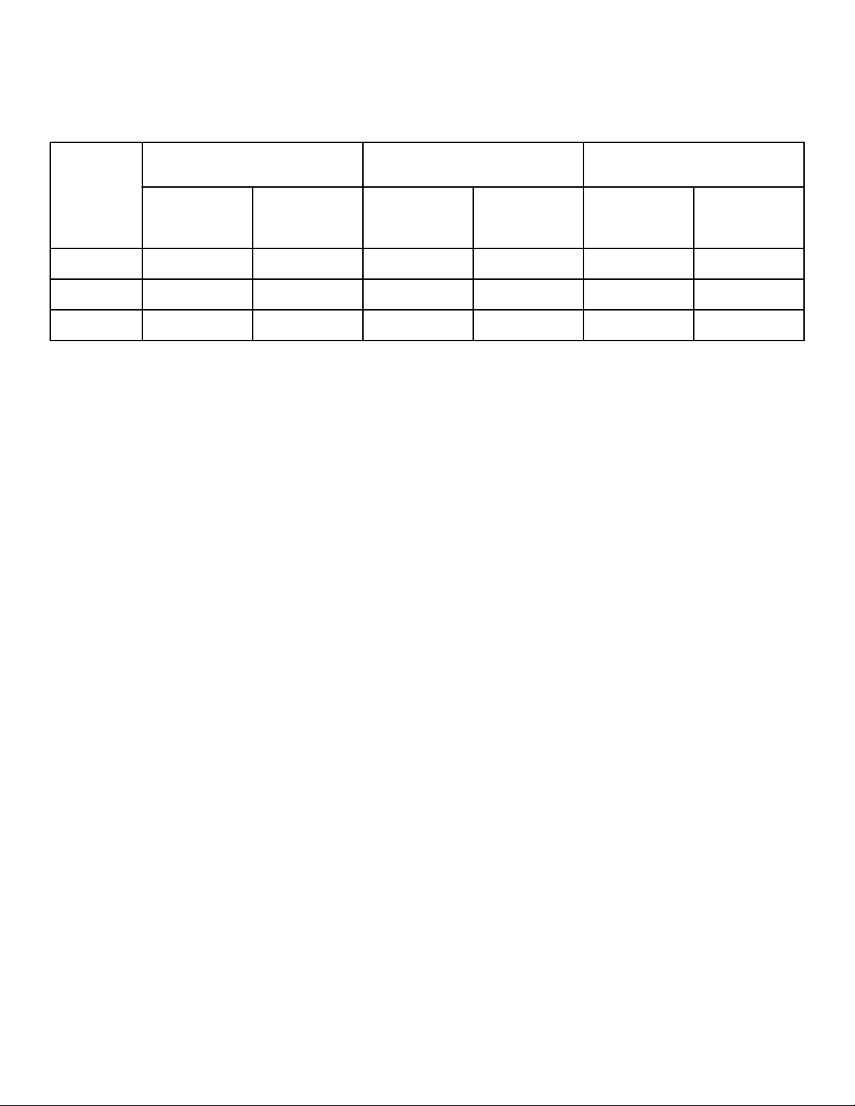
NOTE: Using a Belt Tension Gauge, the motor belt
deflection should be 0.31 inch at five pounds pres-
sure, and final drive belt deflection should be 0.25
inch at five pounds pressure.
Belts should not slip or make any noise when starting up under
normal load.
Drive Motor
Final Drive Blower
Initial
After Run-
in Initial
After Run-
in Initial
After Run-
in
120 60-70 45-55 70-80 55-65 60-70 50-55
170 60-70 45-55 70-80 55-65 75-80 60-65
200 60-70 45-55 70-80 55-65 65-70 55-60
Table 13
Adjustments
©
Copyright, Alliance Laundry Systems LLC -
DO NOT COPY or TRANSMIT
81 Part No. 70458101ENR11
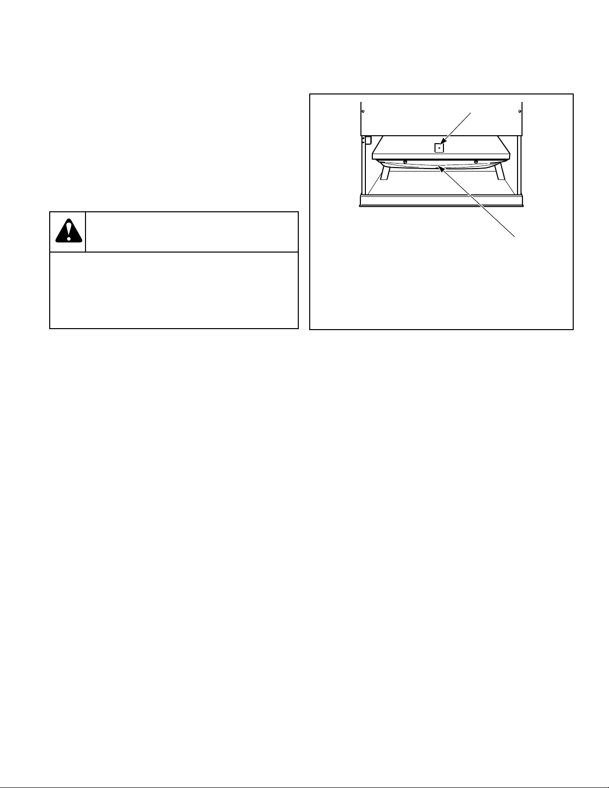
Maintenance
Daily
1. Inspect the area surrounding tumble dryers, remove all com-
bustible materials, including lint, before operating the ma-
chines.
2. Check cylinder for foreign objects to avoid damage to cloth-
ing and equipment.
3. Clean lint from lint compartment and screen to maintain prop-
er airflow and avoid overheating.
WARNING
To reduce the risk of serious injury, do not open
the lint panel while the tumble dryer is in opera-
tion. Before cleaning the lint screen, open tumble
dryer door and allow cylinder to completely stop.
W410R1
a. Open the lint panel.
b. Remove all accumulated lint in the lint compartment area.
Lightly brush any lint that may be left on the lint screen.
c. Be sure the lint screen is not torn.
d. The lint screen is designed to completely cover the entire
opening in the lint screen panel. Be sure that it does so.
e. Wipe lint off of the cabinet high limit thermostat and ther-
mistor. Refer to Figure 49 .
f. Replace the lint compartment panel on the tumble dryer
ensuring a tight fit, and lock if applicable.
4. At end of day, clean the machine's top, front and side panels
with mild detergent. Rinse with clean water. DO NOT use
products that contain alcohol on the control panel.
TMB1266R_SVG
2
1
NOTE: The cabinet high limit thermostat is located
on the rear of the machine near the fan.
1. Thermistor
2. Lint Screen
Figure 49
Monthly
1. Remove lint and debris from inside exhaust duct to maintain
proper airflow and avoid overheating.
a. Remove external duct and duct access covers, if present.
b. Clean inside of duct with a vacuum.
c. Clean dampers and make sure they operate freely.
d. Replace duct and all access covers before returning tumble
dryer to operation.
2. Ensure even lint distribution over lint screen.
3. Carefully wipe any accumulated lint off the cabinet high limit
thermostat and thermistor, including perforated cover.
4. Clean lint and debris buildup from blower to maintain proper
airflow.
Quarterly
1. Use a vacuum to clean air vents on drive motors.
2. Check and clean steam coils, if applicable.
3. Check flow of combustion and ventilation air.
4. Check belt tension and condition. Replace worn or cracked
belts.
5. Clean the machine's top panel with mild detergent. Rinse with
clean water.
6. Models equipped with a fire suppression system: Perform
the fire suppression system maintenance test by pressing the
test button in the control box.
Maintenance
©
Copyright, Alliance Laundry Systems LLC -
DO NOT COPY or TRANSMIT
82 Part No. 70458101ENR11
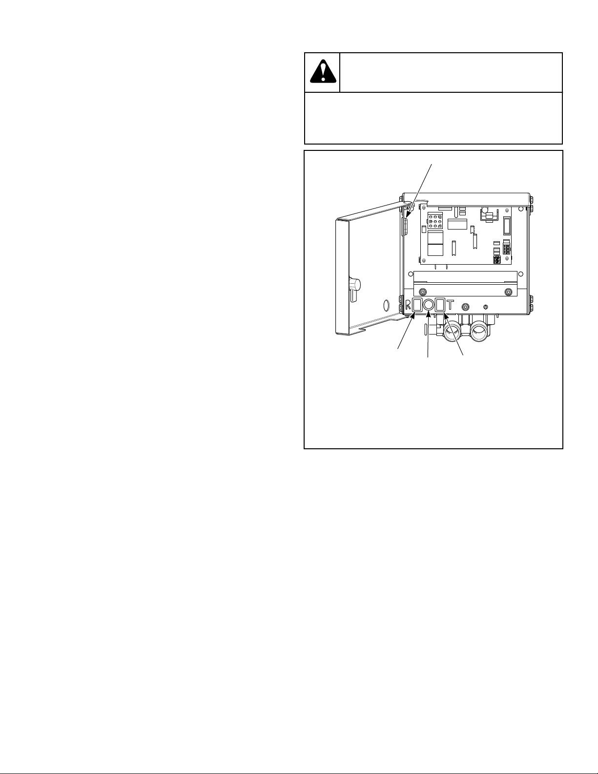
Bi-Annually
1. Check mounting hardware for any loose nuts, bolts or screws.
2. Check gas connections for leakage.
3. Check for loose electrical connections.
4. Check steam connections for looseness and leakage.
5. Check steam filter. Replace if dirty.
6. Remove all front panels and vacuum, including coin drop
mechanisms.
7. Check cylinder and front panel seals.
8. Inspect cabinet and inner panels for any damage, replace or
repair as needed.
9. Clean burner tubes and orifice area of any lint buildup.
10. Machines equipped with a fire suppression system: All in-
let and outlet hoses should be checked for any visible signs of
deterioration. Replace as necessary or every five years.
Annually
1. Remove burner tubes.
2. Clean burner tubes using water and a brush.
Fire Suppression System (Optional
Equipment) Maintenance Test
NOTE: Fire suppression system only available on gas
and steam models.
To ensure proper operation, the fire suppression system must be
tested every three months. If the system test does not perform as
indicated:
1. Discontinue use of the tumble dryer.
2. Refer to Troubleshooting Manual or contact a qualified serv-
ice person.
3. Restore the fire suppression system to proper working order
before using tumble dryer.
Create a maintenance record with a check box for pass, the date
and a signature. Store this record in an area where it will not be
damaged, but is easily accessible to person performing tests.
NOTE: Failure to maintain the fire suppression system
will void the tumble dryer warranty.
NOTE: The auxiliary output is activated during the fire
suppression system maintenance test sequence. Con-
sider this fact prior to testing the system every three
months. (Example – If the external system uses the
auxiliary output to call the fire department, inform the
fire department before and after the fire suppression
system maintenance test.)
CAUTION
Clean up any water spilled during testing to avoid
personal injury.
W487
TMB1999N_SVG2
4
3
2
1
1. Opening for Auxiliary Alarm Cable
2. Test Button
3. Light
4. Reset Button
Figure 50
To perform the fire suppression system maintenance test:
1. If the auxiliary alarm output is connected to a separate alarm
system, disconnect prior to performing the fire suppression
system maintenance test.
2. Remove any lint from the lint compartment.
3. Ensure temperature sensors are free of lint.
4. Place a load of dry towels in the tumble dryer. Refer to Table
14 for proper load size. Ensure the cylinder baffles are to the
left and right of the spray manifold located at the center top of
the cylinder.
5. Unlock the fire suppression system control box.
6. Press and hold the test button, verify the light is on, this
should take approximately five seconds. Refer to Figure 50 .
After a one-second pause water should begin to spray into the
cylinder.
7. After 15 seconds of water spray, press and hold the reset but-
ton until water spray is off and light is off. This should take
approximately one second. Refer to Figure 50 and Figure 51 .
Maintenance
©
Copyright, Alliance Laundry Systems LLC -
DO NOT COPY or TRANSMIT
83 Part No. 70458101ENR11
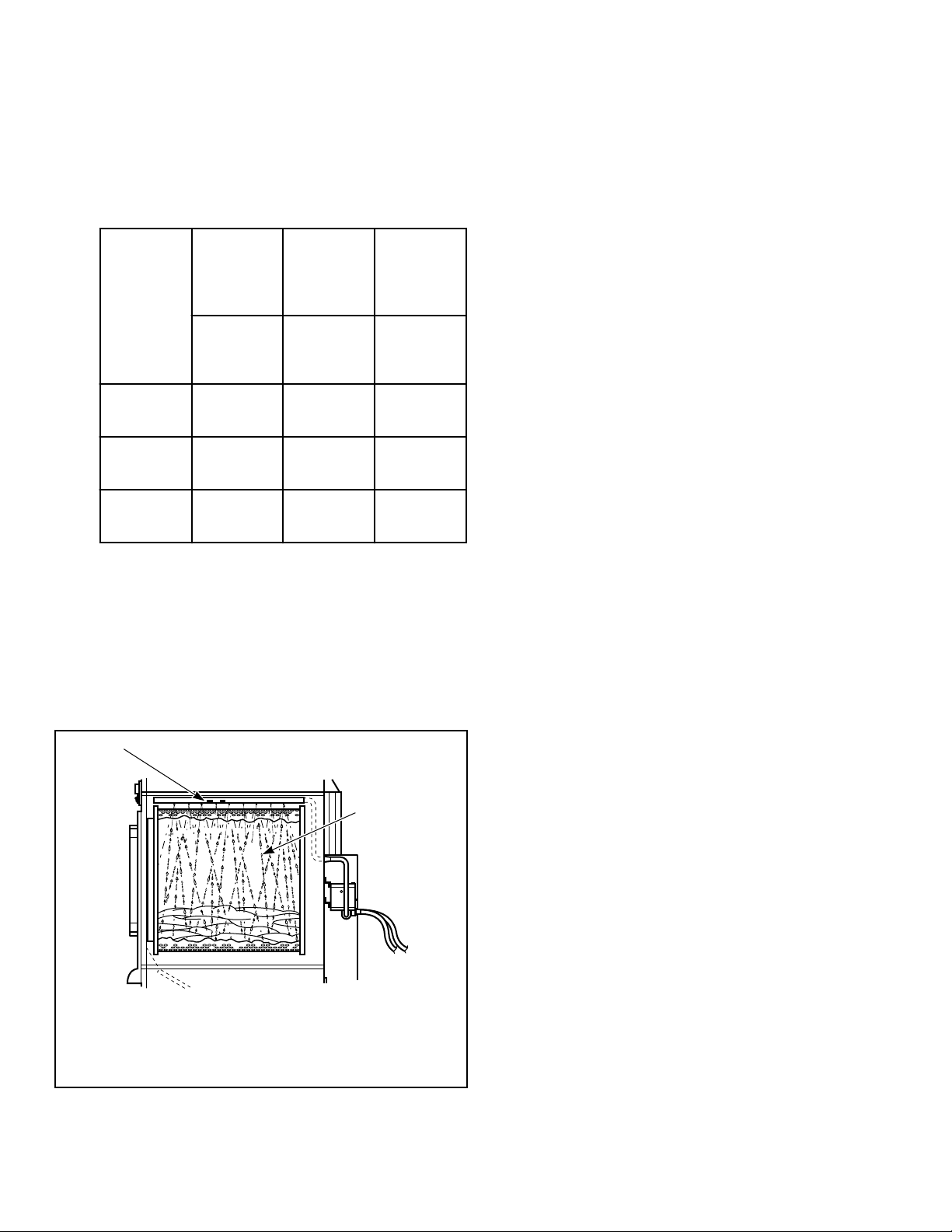
8. Immediately remove and weigh the load. Refer to Table 14
for acceptable weight range. If less than minimum pounds in-
dicated in Table 14 , the fire suppression system has failed the
maintenance test. Refer to the Troubleshooting Manual.
IMPORTANT: If the fire suppression system failed
the maintenance test, DO NOT operate the tumble
dryer.
Dry
Weight
Wet
Weight
Mini-
mum
Weight
lbs.
[kg]
lbs.
[kg]
lbs.
[kg]
120 60 [27] 75-79
[34-36]
70 [32]
170 80 [36] 95-99
[43-45]
90 [41]
200 100 [45] 115-119
[52-54]
110 [50]
Table 14
9. Clean up any water on the floor.
10. Lock the fire suppression system control box.
11. If the separate alarm option is being used, reconnect the auxil-
iary alarm output.
12. Start the tumble dryer to dry the test load.
13. On maintenance record, check box if fire suppression system
passed the test, date and sign record.
TMB2010N_SVG
2
1
1. Spray Manifold
2. Water Spray
Figure 51
Maintenance
©
Copyright, Alliance Laundry Systems LLC -
DO NOT COPY or TRANSMIT
84 Part No. 70458101ENR11
Before You Call for Service
Won’t Start Won’t Heat Clothes Not Dry Possible Reason – Corrective Actions
• Insert correct coin(s) or valid card if applicable.
• Close the loading door tightly.
• Close lint panel tightly.
• Press the PUSH-TO-START or START pad/button.
• Be sure power cord is plugged all the way into the elec-
trical outlet.
• Drying timer is in OFF position.
• Check the main fuse and circuit breaker.
• Check fuses located in the machine.
• Insufficient airflow.
• Gas shut-off valve in OFF position.
• Are controls properly set?
• Broken drive belt. Call the service person.
• • Tumble dryer is in Cool Down Mode.
• • Lint screen clogged. Clean lint screen.
• • Exhaust duct to outside is blocked. Clean out.
Before You Call for Service
©
Copyright, Alliance Laundry Systems LLC -
DO NOT COPY or TRANSMIT
85 Part No. 70458101ENR11

Removing Tumble Dryer from Service
1. Turn off electrical supply external to machine.
2. Turn off electrical disconnect on machine.
3. Turn off gas supply external to machine.
4. Turn off manual gas shut-off valve on machine.
5. Turn off steam supply external to machine.
6. Remove all electric, gas and steam connections.
Removing Tumble Dryer from Service
©
Copyright, Alliance Laundry Systems LLC -
DO NOT COPY or TRANSMIT
86 Part No. 70458101ENR11
Disposal of Unit
This appliance is marked according to the European directive
2002/96/EC on Waste Electrical and Electronic Equipment
(WEEE).
This symbol on the product or on its packaging indicates that this
product shall not be treated as household waste. Refer to Figure
52 . Instead it shall be handed over to the applicable collection
point for the recycling of electrical and electronic equipment. En-
suring this product is disposed of correctly will help prevent po-
tential negative consequences for the environment and human
health which could otherwise be caused by inappropriate waste
handling of this product. The recycling of materials will help to
conserve natural resources. For more detailed information about
recycling of this product, please contact the local city office,
household waste disposal service, or the source from which the
product was purchased.
MIX1N_SVG
Figure 52
Disposal of Unit
©
Copyright, Alliance Laundry Systems LLC -
DO NOT COPY or TRANSMIT
87 Part No. 70458101ENR11