Loading ...
Loading ...
Loading ...
1
7.1 General Check
(1) Make sure that the field-supplied electrical
components (main power switches, circuit breakers,
wires, conduit connectors and wire terminals) have
been properly selected according to the electrical
datagiven in “Technical CatalogⅠ” . Make sure that
thecomponents comply with National Electrical Code
(NEC).
(2) Use shielded twist pair cable for transmission
wiring between outdoor unit and indoor unit, remote
controller wiring between indoor units and remote
control switch.
(3) Check to ensure that the power supply voltage is
within ±10% of the rated voltage.
(4) Check the capacity of the electrical wires.
If the power source capacity is too low, the system
cannot be started due to the voltage drop.
(5) Check to ensure that the earth wire is connected.
(6) Power Source Main Switch.
Install a multi-pole main switch with a space of94
(5) or more between each phase.
7.27.2 Electrical W
iring Connection
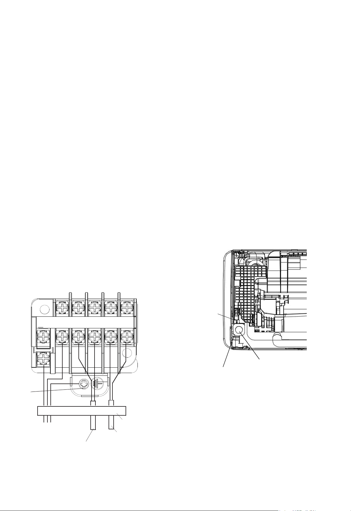
The electrical wiring connection for the indoor unit
is shown in Fig. 7.1.
(1) Unscrew and remove the conduit mount plate
from the machine base. Fix a conduit for power
supply wiring to the plate with a lock nut and reattach
them at original position.
(2) Connect the wires of an optional remote control
switch to A, B terminals of the terminal board inside
the electrical box through the connecting hole in the
cabinet.
(3) Connect the wires between the indoor unit and
the outdoor unit to1, 2terminals of the terminal
boardinside the electrical box through the
connecting holein the cabinet.
(4) Connect power supply wires to L1, L2 and
connect earth wire to the earth. Please connect to the
power circuit with a ELB.
(5) Check to ensure that the terminal specification is
applied to the screw (M3.5 for power supply and
operating line) of the terminal box.
(6) Fix all the wires securely with cord clamp.
Remote Controller Wiring
Indoor and Outdoor
Transmission Wiring
Fig.7.1 Wiring Connection
Power Supply
08/3060Hz
Earth Wiring
Screw
Cord Clamp(All wirings are
fixed with cord clamp)
L1 L2
1 2 A B
Hole for Power Wiring
Conduit Mounting Plate
For the minimum size of field-supplied power
cord, please refer to Section 10.1.
Screw
C
T
Loading ...
Loading ...
Loading ...