
OWNER’S MANUAL
Thank you for choosing JL Audio loudspeakers for
your automotive sound system.
We strongly recommend that you have your new loudspeakers installed by
an authorized JL Audio dealer. Your authorized dealer has the training,
expertise and installation equipment to ensure
optimum performance of these loudspeakers in your vehicle.
If you decide to install the loudspeakers yourself, please read this manual
thoroughly to familiarize yourself with their installation
requirements and setup procedures.
Should you have any questions regarding the instructions in this manual,
please contact your authorized JL Audio dealer for assistance, or call the
JL Audio Technical Support Department at (954) 443-1100
during business hours (USA - Eastern Time Zone).
1-inch (25 mm) Component Tweeters
2 | JL Audio - C1-100ct Owner’s Manual
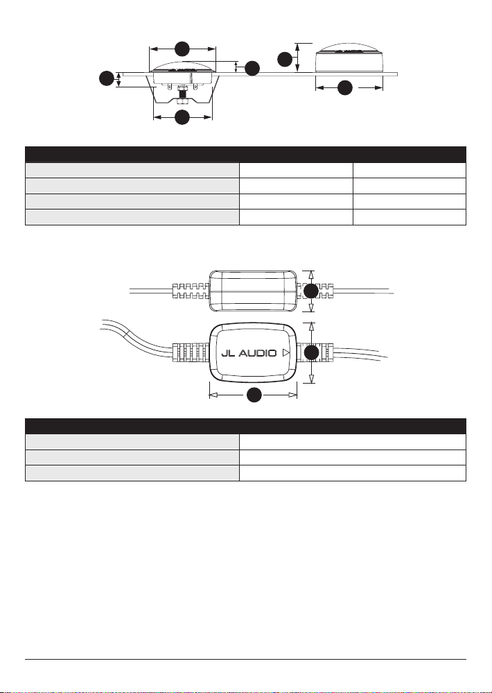
Tweeter Fixture Physical Dimensions Flush-Mount Surface-Mount
Fixture Outer Diameter (A) 1.97 in / 50 mm 2.01 in / 51 mm
Fixture Mounting Hole Diameter (B) 1.75 in / 45 mm N/A
Fixture Mounting Depth (C) 0.40 in / 10 mm N/A
Tweeter Frontal Protrusion (D) 0.32 in / 8 mm 0.87 in / 22 mm
B
A
C
Crossover Network Physical Dimensions
Width (A) 1.96 in / 50 mm
Height (B) 0.90 in / 23 mm
Depth (C) 1.34 in / 34 mm
B
A
D
C
A
D
Due to ongoing product development, all specifications are subject to change without notice.

3
C1-100ct SPECIFICATIONS
Continuous Power Handling: 60 Watts
Recommended Amp Power: 20-60 Watts / ch. (RMS)
Efficiency: 91.5 dB @ 1W / 1m | 97.5 dB @ 1W / 0.5m
Sensitivity: 94.5 dB @ 2.83V / 1m
Nominal Impedance: 4 ohm
Frequency Response: 3.6 kHz - 22 KHz ± 3 dB
Tweeter:
Edge-driven, silk-suspended aluminum dome
1.0 in. (25 mm) diameter diaphragm / voice coil
Ferrofluid cooling / damping
Neodymium Magnet
Crossover:
2nd order, high-pass filter with inductor and
electrolytic capacitor
Included Components and Parts:
• Two (2) C1-100ct 1.0-inch (25 mm) tweeters
• Two (2) surface-mount tweeter fixtures
• Two (2) C1-100cthp in-line, high-pass filters on
4 ft. (1.2 m) wire harnesses
• Two (2) metal spring clips (for tweeter flush-mounting)
• Four (4) #6 x .625-inch (22 mm) sheet metal screws
• Two (2) 10mm stud bolts with fixed M4 nut
• Two (2) 25mm stud bolts with fixed M4 nut
• Two (2) M5 nuts
GETTING STARTED
• Turn off the audio system. It is also
advisable to disconnect the negative
(–) terminal of your vehicle’s battery
whenever performing installation work.
• Before cutting, drilling or inserting any screw,
check clearances on both sides of the planned
mounting surface. Also check for any potential
obstacles, such as window tracks and motors,
wiring harnesses, etc. Check both sides of the
vehicle, many vehicles are not symmetrical!
• Always wear protective eyewear.
4 | JL Audio - C1-100ct Owner’s Manual
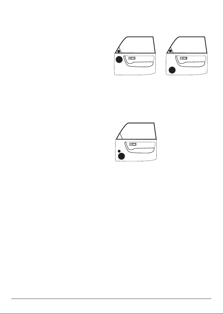
TWEETER PLACEMENT CONSIDERATIONS
A component system gives you the ability
to place the woofer and tweeter separately in
your vehicle interior. This can be good or bad,
depending on how it’s done. As a general rule,
the tweeters should be placed relatively close
to the woofers for best tonal balance and most
coherent imaging (the closer, the better). Any
separation greater than 8 inches (20 cm) is likely
to result in degraded sound quality.
Avoid placing tweeters where they
will be blocked by objects in the interior
of the car (including seated occupants).
When selecting a mounting location, look
at both sides of the car to make sure that
this location is clear on both sides.
You can always experiment with tweeter
placement before committing to a final
mounting location. Simply connect the rest of
the system and allow plenty of wire length for
the tweeters. Using hook and loop fastener or
similar material, attach the tweeters in different
locations until you find the one where they
perform best.
TWEETER PROTECTION
The C1 crossover networks are equipped
with an advanced electronic tweeter protection
circuit designed to minimize the possibility of
tweeter failure. This electronic device monitors
current going to the tweeter and will disconnect
the tweeter from the signal when it senses
overload. Should this occur while listening to
the audio system, simply reduce the volume for
a few seconds and the protection circuit will
reset itself automatically.
DIAGRAM B:
More Desirable Speaker Placement
DIAGRAM A:
Less Desirable Speaker Placement
CROSSOVER NETWORK INSTALLATION
The crossover networks supplied with
your C1 System should be installed in a
dry location inside your vehicle. DO NOT
INSTALL THEM INSIDE OF A DOOR!
Doors often get wet on the inside, which
can damage your crossover networks and
could potentially damage your entire sound
system. Use plastic cable ties or a similar
fastener to securely mount each crossover to
avoid coming loose in the event of a collision,
sudden jolt or repeated vibrations during
normal use. Make sure that your mounting
location will not cause damage to wiring or
any other vital component of your vehicle.
5
TWEETER INSTALLATION
C1 tweeters have been designed for surface
or flush-mounting. Before choosing a method,
carefully inspect the desired mounting location
to determine which method will work best.
Surface-Mount: uses the supplied surface-
mount fixture and requires the drilling of
three holes (one for the wires and two for the
mounting screws). This application is useful
when mounting the tweeters to a panel that has
insufficient clearance behind it for the tweeter’s
magnet structure.
Flush-Mount: yields a custom-installed
appearance and requires a 1-3/4-inch (44 mm)
diameter hole to be cut in the vehicle panel, with
at least 0.40-inch (10 mm) of clearance behind
the mounting surface for the tweeter and up
to 1.45-inch (37 mm) for the stud bolts used to
mount each tweeter.
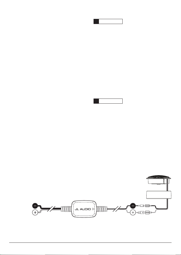
WARNING
!!
Double check the clearance for both speakers
before proceeding. Many cars are different
from one side to the other!
TWEETER CONNECTIONS
Run the wire leads from the crossovers to the
tweeter mounting locations and to the speaker/
amplifier outputs. Then, connect the harness
wire leads to the speaker/amplifier outputs
and tweeters, observing correct polarity. See
Diagram C below for details.
WARNING
!!
It is absolutely vital that your component
tweeter is connected, as shown in Diagram C.
Failure to connect the tweeter as shown will
result in damage which is NOT covered under
warranty. Only use in-line filters clearly
marked “C1-100cthp”.
Fr
om Woofer
or Amplier
Tweeter Crossover
Tweeter
DIAGRAM C:
Tweeter / Crossover Wiring
6 | JL Audio - C1-100ct Owner’s Manual
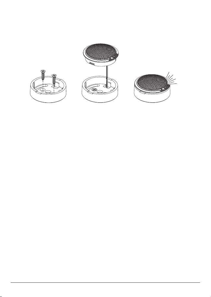
DIAGRAM D:
Surface-Mount Tweeter Installation
CLICK!
SURFACEMOUNT INSTALLATION
1) Remove the vehicle panel and check
to ensure that the mounting screws
will have adequate clearance.
2) Place the surface-mount fixture on the
vehicle panel at the desired mounting
location with the mounting screw holes
positioned vertically, at twelve and six o’clock.
3) Mark the location of the two mounting
screw holes and the approximate center of
the right rectangular cutout (for the wires).
4) Using a 1/16-inch (1.5 mm) drill bit,
drill a pilot hole through the panel
at the two screw locations.
5) Using a 1/4-inch (6 mm) drill bit, drill
the hole for the tweeter’s wires at the
location you marked in step 3.
6) Screw the surface-mount fixture to the
vehicle panel using the supplied #6
sheet metal screws (hand-tighten).
7) Feed the tweeter wires through the
rectangular hole in the mounting fixture and
the 1/4-inch hole you drilled in the panel.
Then, snap the tweeter into the surface-
mount fixture.
8) Connect the tweeter’s wires to the wire leads
from the crossover, observing correct polarity.
9) Re-install the vehicle panel, taking care to
route the new wiring so as not to interfere
with any vehicle mechanisms (window
mechanisms, for example).
7
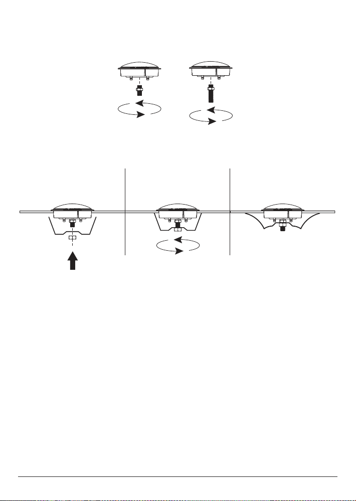
DIAGRAM E:
Flush-Mount Tweeter Installation
< OR >
FLUSHMOUNT INSTALLATION
1) Detach the preinstalled surface-mount fixture
by inserting a small flat screwdriver into the
slots behind the tweeter flange and carefully
pry open to release.
2) Remove the vehicle panel and check the
desired mounting location to ensure that
there is adequate clearance behind the
panel for the tweeter’s magnet structure and
mounting hardware.
3) Carefully cut a 1-3/4-inch (44 mm) diameter
hole in the vehicle panel. This will achieve a
snug fit and allow the tweeter flange to conceal
the cut line.
4) Select a suitable length stud bolt for your
panel’s thickness and screw its short end into
the rear of the tweeter using the fixed M4 nut
to tighten.
5) Insert the tweeter from the front of the panel
(do not attach the spring clip at this time).
6) Attach the spring clip from behind the
panel using the supplied M5 nut and
tighten by hand until the tweeter is tight
on the panel. Do not overtighten.
8) Connect the tweeter’s wires to the supplied
harness with the in-line high-pass filter,
observing correct polarity.
9) Re-install the vehicle panel, taking care to
route the new wiring so as not to interfere
with any vehicle mechanisms (window
mechanisms, for example).
Stud bolts are provided in two lengths to accommodate different panel thicknesses.
10 mm length 25 mm length

Printed in China
LIMITED WARRANTY AUTOMOTIVE SPEAKER SYSTEMS USA
JL AUDIO warrants these speakers (and crossover networks, where applicable) to be
free of defects in materials and workmanship for a period of one (1) year.
This warranty is not transferable and applies only to the original purchaser from an
authorized JL AUDIO dealer. Should service be necessary under this warranty for any
reason due to manufacturing defect or malfunction, JL AUDIO will (at its discretion),
repair or replace the defective product with new or remanufactured product at no charge.
Damage caused by the following is not covered under warranty: accident, misuse, abuse,
product modification or neglect, failure to follow installation instructions, unauthorized
repair attempts, misrepresentations by the seller. This warranty does not cover incidental or
consequential damages and does not cover the cost of removing or reinstalling the unit(s).
Cosmetic damage due to accident or normal wear and tear is not covered under warranty.
Any applicable implied warranties are limited in duration to the period of the express
warranty as provided herein beginning with the date of the original purchase at retail, and no
warranties, whether express or implied, shall apply to this product thereafter. Some states do
not allow limitations on implied warranties, therefore these exclusions may not apply to you.
This warranty gives you specific legal rights, and you may also have other rights which vary
from state to state.
If you need service on your JL AUDIO product:
All warranty returns should be sent to JL AUDIO freight prepaid through an authorized
JL AUDIO dealer and must be accompanied by proof of purchase (a copy of the original sales
receipt.) Direct returns from consumers or non-authorized dealers will be refused unless
specifically authorized by JL AUDIO with a valid return authorization number. Warranty
expiration on products returned without proof of purchase will be determined from the
manufacturing date code. Coverage may be invalidated as this date is previous to purchase
date. Return only defective components. If one speaker fails in a system, return only that
speaker component, not the entire system. Non-defective items received will be returned
freight-collect. Customer is responsible for shipping charges and insurance in sending
the product to JL AUDIO. Freight damage on returns is not covered under warranty.
For Service Information in the U.S.A. please call
JL Audio Customer Service: (954) 443-1100
9:00 AM – 5:30 PM (Eastern Time Zone)
JL Audio, Inc
10369 North Commerce Pkwy.
Miramar, FL 33025
International Warranties:
Products purchased outside the United States of America are covered only
by that country’s distributor and not by JL Audio, Inc.
C1-100ct-011817