

To our customers
1. Dear customers, please read this manual carefully before you install the product, otherwise
it may lead to damage to the heat pump or may injure operators as well as cause financial loss.
2. With the development of science and technology, the product will be improved as well, so you
are invited to keep up with the latest products.
3. If you need any further technical information, please contact our local distributor.
4.Attention:
4.1 Before install the heat pump, please check whether the local power supply corresponds with
the requirement of the heat pump.
For details, refer to the label on the unit or performance data in this manual.
4.2 Please install the electrical protection devices, according to the local regulations.
4.3 Connecting the heat pump to a ground wire is necessary, in order to prevent electrical shock
caused by an unexpected short circuit inside the unit.
4.4 An electrical wiring diagram is provided in this manual.
4.5 For safety reasons, please do not change or repair the heat pump by yourself. If it is necessary,
please contact your local distributor for help.
4.6 Do not put any objects into the heat pump when running. It may touch the fan and damage it
or lead to accidents(especially for the children).
4.7 Do not use the heat pump without the grid or plate work since it may lead to accidents or ab
normal operation of the unit.
4.8 If the unit is soaked in water, please contact our local distributor immediately.
The unit can only be restarted after a completed inspection by professional technicians.
4.9 Unqualified technicians are not allowed to adjust any switches, valves or controllers in the unit.

Contents
1. Performance data and installation
1.1 Performance and features
1.2 Working principles
1.3 Location of the heat pump
1.4 Distance from the pool
1.5 Installation of the check-valve
1.6 Pool system set up
1.7 Connecting the by-pass
1.8 Electrical hook -up
1.9 First time start-up
1.10 Condensation
4.Protection systems
4.1 Water flow switch
4.2 Refrigerant gas high and low pressure protection
4.3 Automatic defrost control
4.4 Temperature difference between inflowig and outflowing water
4.5 Low temperature cut-out
4.6 Anti-frost protection during winter
4.7 First anti-frost protection
4.8 Second anti-frost protection
7.Name plate & wiring diagram
7.1Name plate
7.2 Wiring diagram
1
1
2
3
3
4
4
5
6
6
16
16
16
16
16
16
16
16
24
25
8.FIBROHEAT HEAT PUMP LIMITED FACTORY WARRANTY
26
2. Control the heat pump (LCD)
2.1 The functions of the wire controller
2.2 How to change desired temperature
2.3 How to change mode
2.4 How to set operation parameter
2.5 How to know current status
2.6 Controller lock
7
7
8
8
10
10
3. Control the heat pump (LED)
3.1 Illustration of controller
3.2 How to change desired temperature
3.3How to start heat pump
3.4 How to change mode
3.5 How to set desired water temperature
3.6 How to change parameter setting
3.7 How to check parameter setting&measured values of current status
3.8 How to set the clock
3.9 How to set timer on and timer off
3.10 How to cancel timer on and timer off
3.11 Keypad lock and unlock
11
11
12
12
12
13
13
15
15
15
15
5.1 Swimming pool water chemistry
5.2 Heat pump winterizing
5.3 Restarting the pump after winter
5.4 Check-up
5.Direction
17
17
17
18
6.Maintenance and inspection
6.1 Maintenance
6.2 Trouble shooting guide
6.3 Failure code table for single-system
6.4 Failure code table for double-system
19
19
22
23
1. Performance and installation
1.1 Performance and features
Cooler
De-energized Air
Warm
Air
Fan
Evaporator
(Energy Collector)
Capillary Tube
Condenser
(Water Heat Exchanger)
Pool Filter
Pump
Compressor
Swimming pool
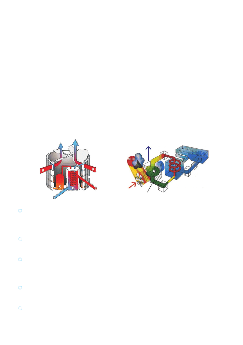
1.2 Working principles
High efficiency
With a COP value up to 5.0 our heat pumps are very efficient when transferring heat from the air to
the swimming pool water. You can save as much as 80% of cost compared to an electrical heater.
Long life-span
The heat exchanger is made of PVC & Titanium tube, which can withstand and prolong exposure to
swimming pool water.
Easy control and operation
The unit is very easy to operate: simply switch it on and set the desired pool water temperature.
The system includes a micro-computer controller, allowing all operation parameters to be set.
Operation status can be displayed on the controller with LCD display.
Heat pumps utilize the sun's free heat by collecting and absorbing energy from the outside air. This
energy is then compressed and transferred to the pool water. Your existing water pump circulates the
water through the heater, usually next to the pool equipment, and the water warms up. The heat pump
timer could be set to operate during daylight hours, for example, usually 9am to 5pm.
The unit contains a fan that draws in outside air and directs it over the surface of the EVAPORATOR
(energy collector).The liquid refrigerant within the EVAPORATOR coil absorbs the heat from the
outside air becomes a gas.
The warm gas in the coil passes through the COMPRESSOR concentrating and increasing the heat to
form a very hot gas which then passes to the CONDENSER (water heat exchanger).It is here that the
heat exchange occurs as the hot gas gives off heat to the cool swimming pool water circulating through
the coil.
The pool water becomes warmer, and the hot gas cooling as it flows through the CONDENSER coil-
returns to its liquid form and, after passing on through the CAPILLARY TUBE, the whole process
begins again.
The state of the heat pump technology can efficiently collect heat from the outside air down to the 7℃ to
10 range. For tropic and subtropical climates, this means that the pool can be maintained at 26℃ to 32℃
Heat exchanger
Water flow out
Evaporator
Air flow
Compressor
Air flow
Water flow in
1
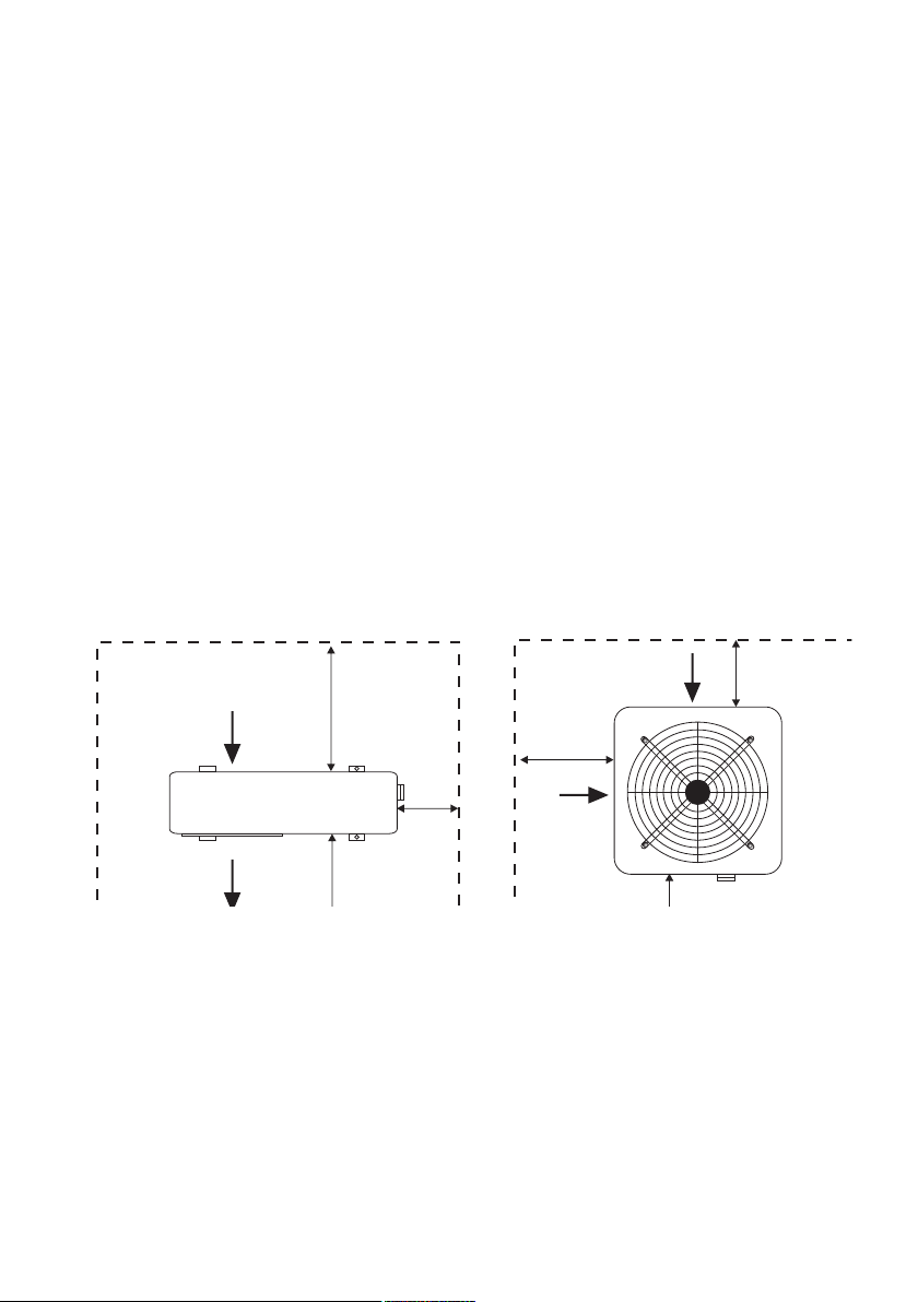
1.3 Location of heat pump installation
The unit will perform well on any location provided three factors are present:
1. Fresh air - 2. Electricity - 3. Pool filter piping
The unit may be installed virtually anywhere outdoors providing minimum distance requirements are met
with respect to other objects (see diagram below).For indoor pools please consult your installer. If the unit
is placed in a windy area, no problems occur with e.g. the pilot light, as opposed to what is often the case
with gas heaters.
Attention: Do not place the unit in an enclosed area with a limited air volume where the unit's discharged
air will be re-circulatedor near shrubs that could block the air inlet. These locations deny the unit a
continuous fresh air supply, which reduces its efficiency and may prevent adequate heat yield.
See diagram below for minimum required distances.
Cautions
- Do not put your hands or any other object into the air outlet and fan. It could damage the heat pump and
cause injuries.
- In case any abnormality was found in the heat pump, please cut off the power at once and contact a
professional technician.
- It is strongly suggested to place a guard around the machine to keep children away from the heat pump.
Air out
Air in
Air in
Not less than 500mm
Not less than 2000mm
Not less
than 500mm
Not less
than 500mm
Not less than 500mm from the top
Free space requirement for the horizontal heat pump
Air in
Air in
Air in
More than 500mm
Not less than
500mm
Not less than
500mm
Not less than 1000mm
Not less than 3000mm from the top
Air out
Free space requirement for the vertical heat pump
Model: Vertical Unit
Model: Horizontal Unit
22
1.4 Distance from the pool
Normally, the pool heat pump is installed within a 7.5 meter radius of the pool. The greater the distance
from the pool, the greater the heat loss from the piping. Since the piping is buried for the most part,
heat loss is minimal for distances of up to 30 meters (15 meters to and from the pump= 30 meters total),
unless the soil is wet or the water level is high. Heat loss per 30 meters could roughly be estimated at 0.6
kw-hour (2000 BTU) for every 9 temperature difference between the pool water and the soil
surrounding the pipe, which translates to an operation time increase of 3-5%.
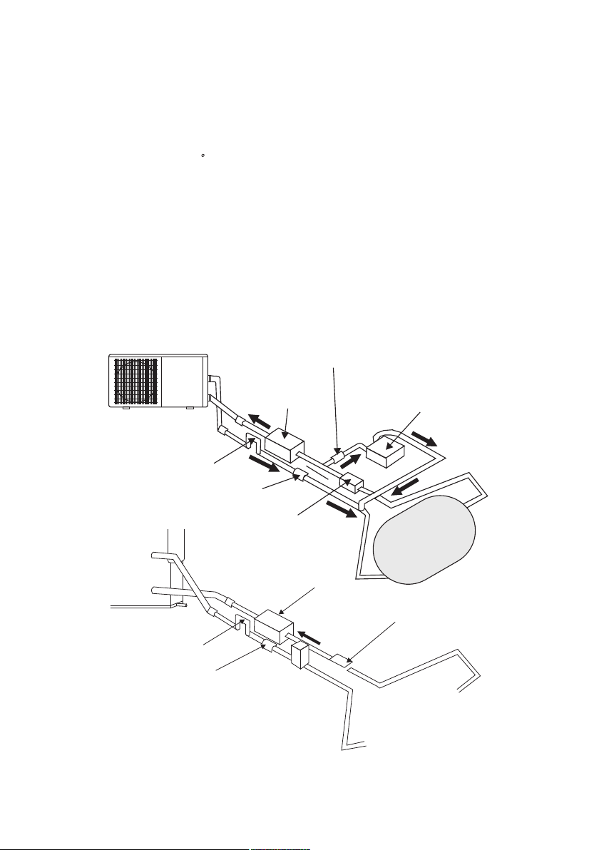
1.5 Installation of the check-valve
Attention- When using automatic chlorine and PH dosage systems, it is of uttermost importance to protect
the heat pump from high concentrations of these chemicals that could corrode the heat exchanger.
Therefore, such systems should add the chemicals in the conduits located DOWNSTREAM of the heat
pump and it is recommended to install a check-valve in order to prevent backflow when there is no water
circulation.
Damage to the heat pump caused by disregarding any of these recommendations will invalidate the warranty.
Water Pump
P-trap
Check-valve
Filter
Chlorinator
Check-valve
Swimming Pool
P-trap
Check-valve
Filter
Chlorinator
Water Pump
Swimming Pool
3
F
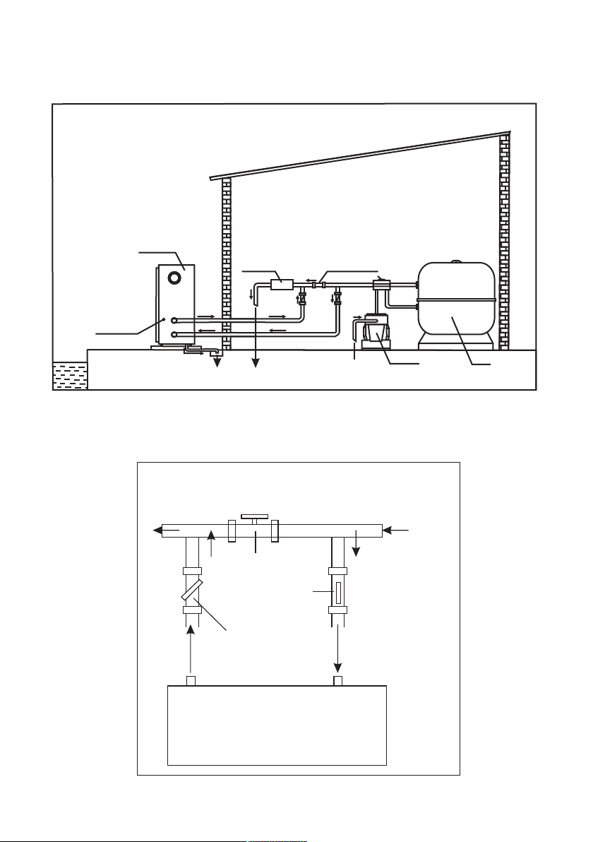
1.6 Pool system set up
1.7 Connecting the by-pass
Valve 1
Valve 2
Valve 3
BY-PASS
F
r
o
m
f
i
l
t
e
r
T
o
p
o
o
l
OUT IN
HEATPUMP
Power cable inlet
Heat Pump
Outlet
Inlet
Condensed water draining pipe
Draining nozzle
Discharge water to pool
Pool water inlet
Water pump
Filter
Water processor
Side connection valve
4
2
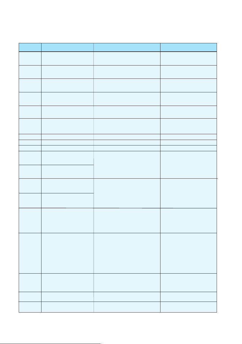
Cable diameter(mm )
(for max.length of 15 meters
2x2.5+2.5
2x2.5+2.5
2x2.5+2.5
2x2.5+2.5
2x4.0+4.0
2x4.0+4.0
2x6.0+4.0
4x2.5+2.5
4x2.5+2.5
4x2.5+2.5
4x2.5+2.5
4x4.0+2.5
4x4.0+2.5
4x4.0+2.5
Output
Voltage(volt)
Fuse(A)
Nominal current(A)
3.8kW
5.6kW
7.8kW
9.5kW
12.5kW
14.0kW
17.0kW
14.0kW
17.0kW
21.0kW
26.0kW
35.0kW
45.0kW
50.0kW
220-240
220-240
220-240
220-240
220-240
220-240
220-240
3x380
3x380
3x380
3x380
3x380
3x380
3x380
10
10
16
16
20
25
32
10
10
16
16
25
25
25
3.9
5.7
7.9
9.7
12.7
14.2
17.2
5.3
6.4
8.0
9.8
12
14
16
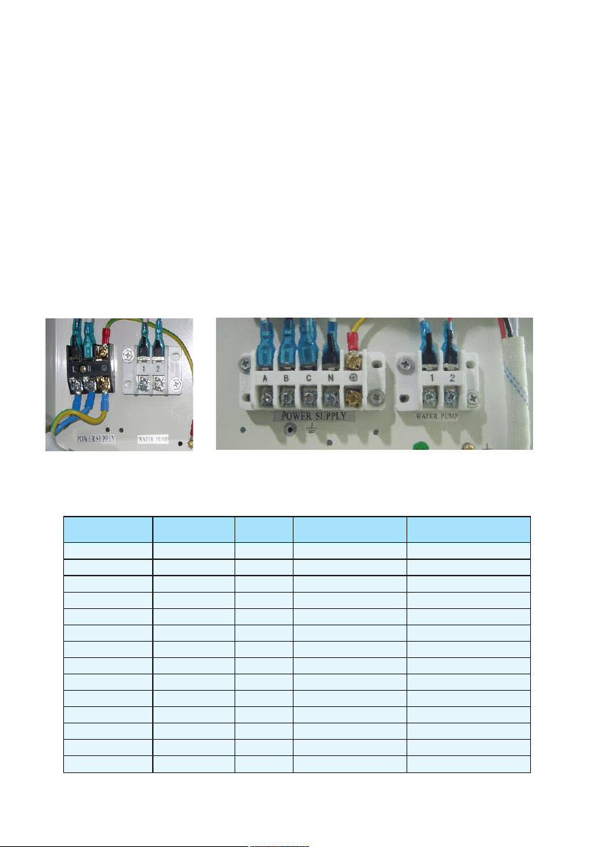
Important—Although the heat pump is electrically isolated from the rest of the unit, this only prevents
the passage of electricity to or from the pool water. Grounding the unit is still required to protect
yourself from short circuits inside the unit. Make for adequate ground connection.
Check if the electrical mains voltage corresponds with the operating voltage of the heat pump prior to
hooking up the unit.
It is recommended to use a separate fuse(slow type-D-curve)as well as adequate wiring(see table below).
For horizontal models : remove the panel on the right of the fan opening.
For vertical models: remove the curve panel in the front side.
Connect the electrical wires with the terminal block labelled “Power Supply” .
Next to this connection, there is a second terminal block labelled “ Water Pump”,to which the filter
pump (max.5A/240V)can be connected. This is connection makes it possible to control filter pump
operation with the heat pump. See further at Parameter setting table (Parameter 9) for the different
possibilities.
Remarks—for models with 3 phases, switching 2 phases may cause in inversion in the rotational direction
of electrical motors, which could damage the unit. Therefore, a protection device has been built in, which
will interrupt the circuit if the connection has not been performed correctly.
1.8 Electrical hook-up
5

1.10 Condensation
1.9 First time start-up
Time delay— the unit is equipped with a built-in 3-minute start delay included to protect electrical
components and contacts. After this tim e d ela y, the un it wil l a utomaticall y b e r est arted. Even a
brief interruption of the power supply will activate the start delay and prevent the unit from starting
immediately. Additional interruptions of the power supply during the delay period will have no effect
on the 3-minute countdown.
Water flow switch—the unit is equipped with a flow switch that is switched on when enough water has
flowed through the unit and that is switched off when the water flow becomes too low. (E.g. When the
filter pump is switched off).
When the swimming pool water is being heated by the heat pump, the incoming air is cooled down quite
a bit, which can cause condensation on the fins of the evaporator. Condensed volumes can attain several
litres per hour under high atmospheric humidity. Sometimes, this is wrongfully interpreted as a water leak.
Depending on the starting temperature of the pool water and the air temperature, it can take several days
for the water to reach the desired temperature. Covering the pool can drastically reduced this period.
When all connections have been made and checked, you should follow these steps:
1. Turn on the filter pump. Check for leaks and verify flow to and from the pool.
2. Turn on the electrical power supply to the unit, then press the ON/ OFF key on the electronic control
panel. The unit should start when the time delay period has lapsed .
3. When the unit has been running for a couple of minutes, check if the air leaving the unit is cooler.
4. Check the performance of the flow switch as follows: with the unit running, turn the filter pump off.
The unit should also switch off automatically. If not, the flow switch must be readjusted.
5. All the unit and filter pump to run 24 hours a day until the desired pool water temperature is reached.
When the set temperature is reached, the unit switches itself off. The unit will now automatically restart
(as long as your filter pump is running) when the temperature of the pool water experiences a drop of
more than 34 below the set temperature.
Note- In order for the unit to heat the pool (or spa), the filter pump must be running so that the water
can circulate through the heat pump. Without this circulation, the heat pump will not start.
6
F
2. Control the heat pump (LCD)
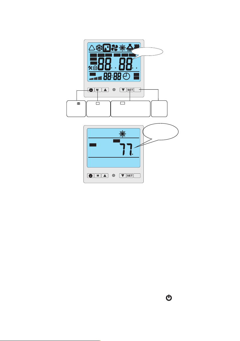
2.1 The functions of the wire controller
ROOM
AUX
Standby status
The LCD display ambient
temp. and current mode
TEMP
1
2
MIN
TEMP
ON
OFF
%
h
%
C F
C F
AUTO
h
MIN
IN
S
E
T
VALVE
OUT
ROOM
NO.
HUM
FAN
AUX
Initialization
Press to
turn on and
turn off the
units.
Press button
to change modes
M
Press to set operation
parameter under stand by
status,or check the operation
parameter under running
or stand by status.
Set
Invalid
button
7
F
2.2How to change desired temperature
Notes:
1. You cannot change the temperature while the heater is running (2 temperatures on
digital display= Running Mode)
2. You must put the heater on "Stand By" mode, by pressing the " " button on the
digital controller to change the temperature ( 1 temperature on digital display= Stand By mode)
3. If you wait too long, the screen will revert back to temperature display. Simply, press
the “SET” button again until you reach "01"
To adjust the temperature of the heater (Fh 055 and FH 109), the heater must have power to it,
and must be on stand by mode.
1. Turn on the heaters breaker and be sure the pool pump is on.
2. Look at the screen, and if you see only 1 temprerature reading go to Step 4
3. If you see 2 temperature readings, then press the first button( the on/ off button, O with
the slash) once until you see only 1 temperature.
4. Press the "set" button until it displays "01". I fyou miss it, wait 5 seconds and the screen
will reset.
5. Move the up and down arrow keys until you reach the desired temperature.
6. Wait 5 seconds, menu will return to normal screen with 1 temperature reading.
7. Push the on/ off button once to turn the heater on.
8. Wait 45 seconds for the memory to record and a diagnostic chek.
The heater will start automatically
TEMPERATURE CANNOT BE CHANGED WHILE THE UNIT IS HEATING. PLEASE
PUSH THE ON/OFF BUTTON TO PUT THE UNIT ON STANDBY MODE TO MAKE CHANGES
Press“M”,◎ to choose the (Auto ,cooling ,heating )mode one by one under the stand by status and
running status.
AUXSET
M
Auto Mode
AUXSET
M
AUXSET
M
Cooling Mode
Heating Mode
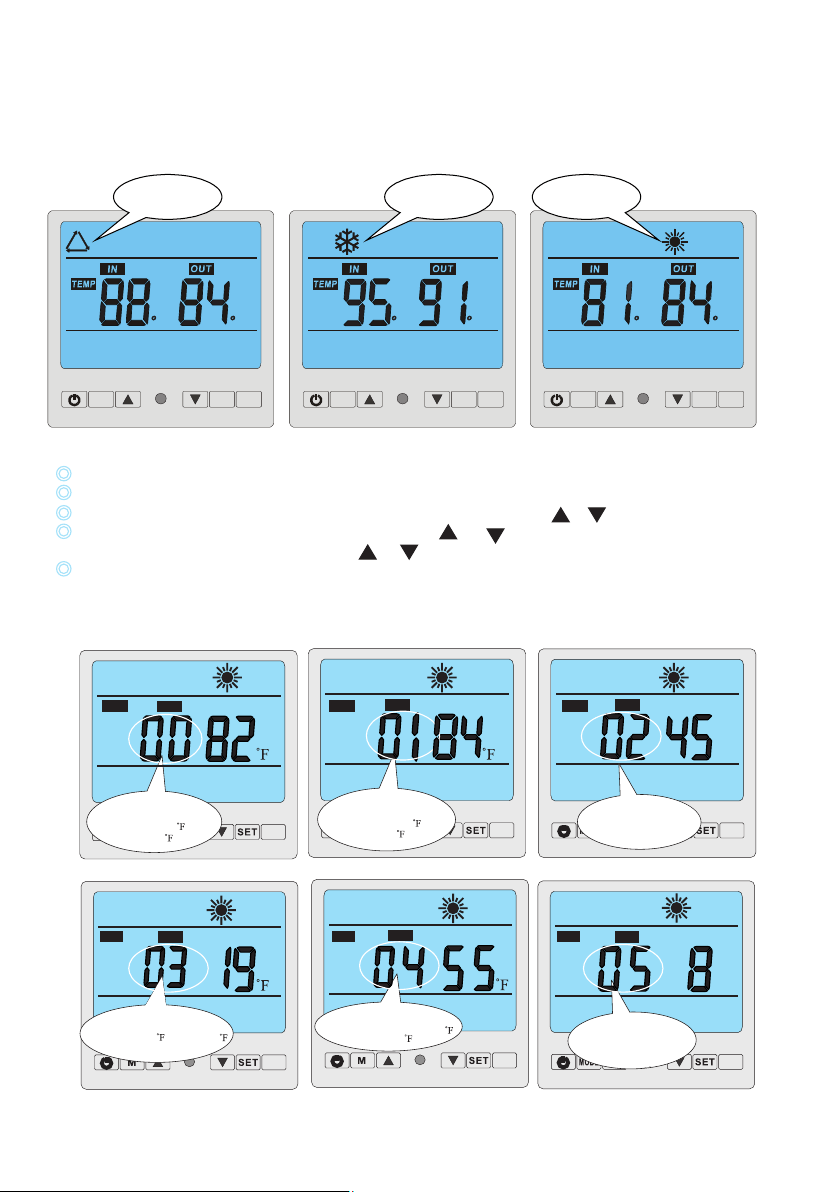
2. 4 How to change parameter
When heat pump is in standby status, Press “SET”button to enter Parameter setting interface
Press “SET” again to start setting Parameter from 00 -10(see Parameter Table)
In parameter setting Parameter 00-01 can be changed only by pressing or .
Parameter 02-10 must be firstly unlocked by pressing and at the same time for 3-5 seconds until a
sound of “Beep” is heard. Then press or to change the setting.
Data will be stored in 3-5 seconds without any press on the controller and display will return to
main interface. Parameter 02-10 must be adjusted by professional technicians.
Important: Whilst running, all parameters can be only checked by pressing “SET”button,but never
be changed!
2.3How to set operation parameter
F F F F F F
NO.
AUX
Parameter 03
Evaporator temperature set point for starting
defrosting ( 32 - -22 )Default setting19 ,
“-” can not be displayed.
S
E
T
NO.
AUX
3
5
Parameter 04
Evaporator temperature set point
for stopping defrosting (36-86 )
Default setting 55
S
E
T
NO.
AUX
MIN
3
5
S
E
T
NO.
AUX
Parameter 02
Defrosting cycle(30-90min)
MIN
SET
AUX
Parameter 00
Desired water temperature in
cooling mode (46-82 )
default setting:28
NO.
SET
NO.
AUX
Parameter 01
Desired water temperature in
heating mode (59-104 )
default setting:29
SET
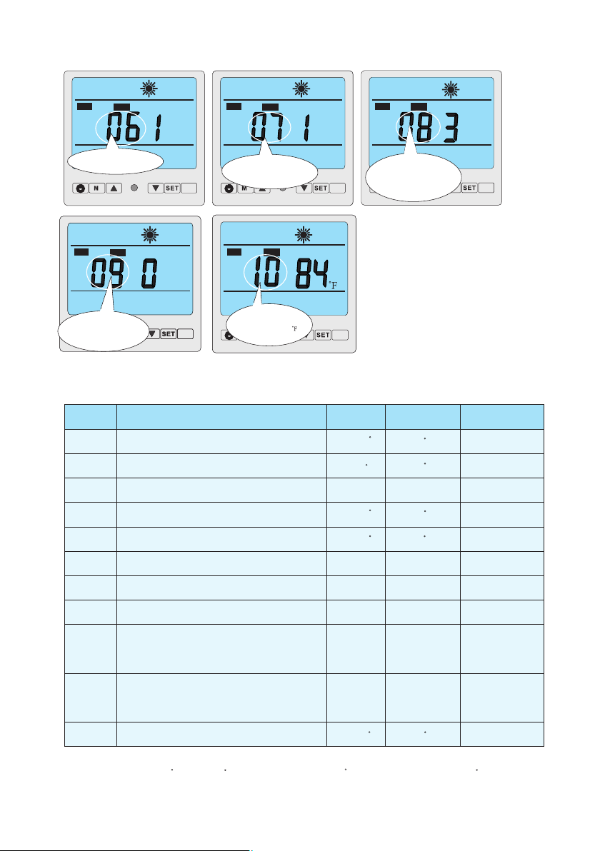
Parameter 05
Maximum duration for
defrosting (1-12 min)
Default setting 8 min
8
NO.
AUX
S
E
T
VALVE
NO.
AUX
NO.
AUX
Parameter 07
Restart after power
failure.
S
E
T
NO.
AUX
Parameter 08
Type:
0 cooling only
1 cooling&heating
2 auxiliary elec heating
cooling+heating
3 heating only
S
E
T
VALVE
NO.
AUX
NO.
AUX
Parameter 09
Different working mode of
water pump.
S
E
T
C
VALVE
NO.
AUX
NO.
AUX
Parameter 10
Desired water temperature
in auto mode (46-104 )
S
E
T
Parameter 06
Number of compressors
in the system
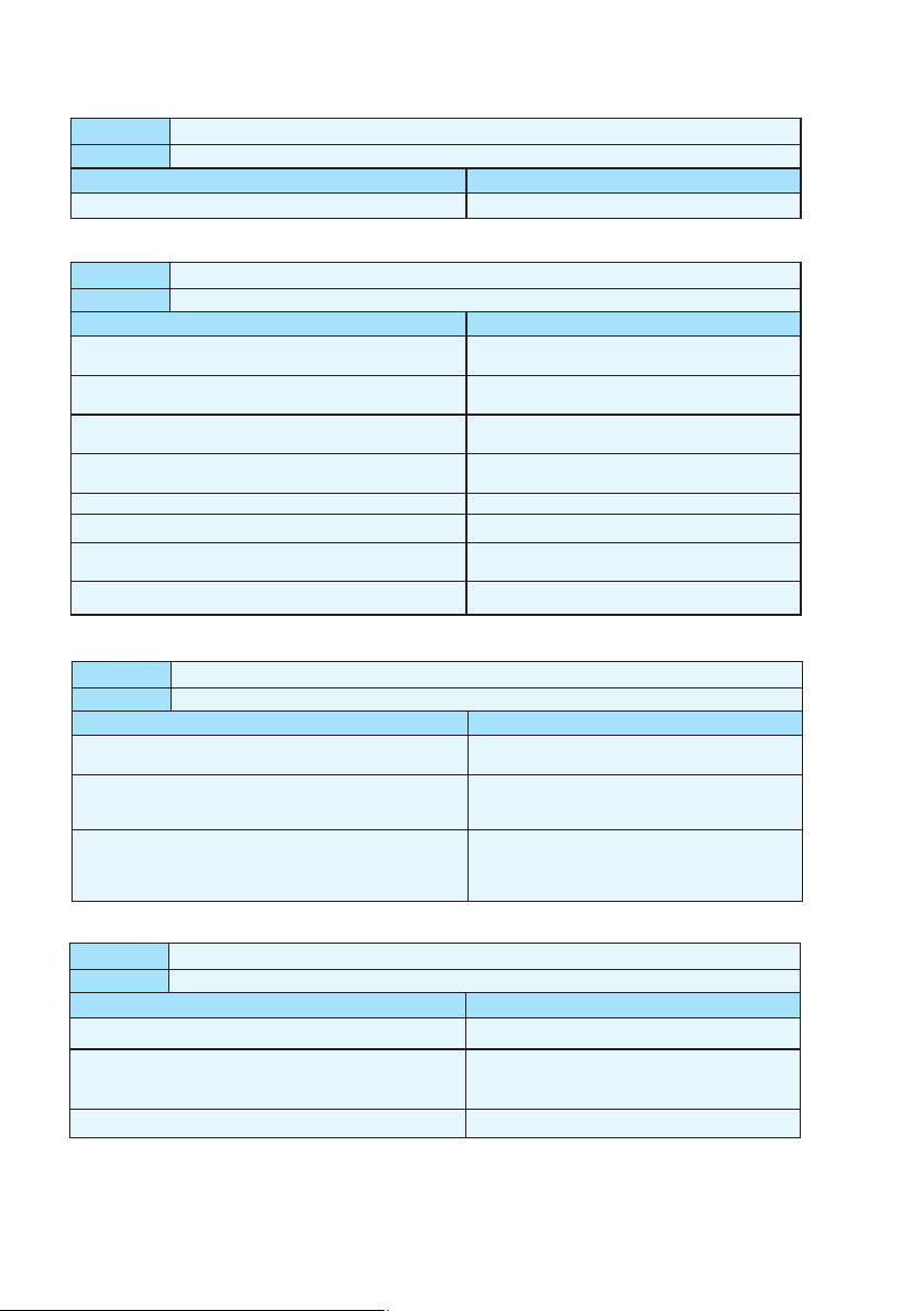
The heat pump's running setting parameter can be set on the wire controller.
Please set the parameter according to the below table:
Parameter
Definition
Range
Default
Remark
00
01
02
03
04
05
06
07
08
10
Desired water temperature in cooling mode
Desired water temperature in heating mode
Defrosting cycle
Evaporator temperature set point for stopping
defrosting
Maximum duration for defrosting
Number of compressors in the system
Restart after power failure
Type: Cooling only 0/
Heating &cooling 1/
Heating & cooling + Auxiliary heating 2/
Heating only 3/
Desire water temperature in auto mode
46~82
59~99
30~90Min
37~86
1~12Min
1~2
0~1
0~3
46~99
82
82
40Min
27
55
8Min
1(Yes)
3
82
Ajusted
by Technicians
Ajusted
by Technicians
Ajusted
by Technicians
Ajusted
by Technicians
Ajusted
by Technicians
Ajusted
by Technicians
Ajusted
by Technicians
Ajusted
by Technicians
Ajusted
by Technicians
Ajusted
by Technicians
Evaporator temperature set point for starting defrosting
1
0~1 0
Ajusted
by Technicians
Different working mode of water pump:
water pump keeps working always 0/
water pump works in accordance
with heat pump 1 /
09
-22~32
F
F
F
F
F
F
F F
F
F
Important:Parameter 03 Icon“-”which stands for below“0”degree CAN NOT be displayed here.
Value“30-22”stands“30 ”to“-22 ”. Default setting“19 ”actually stands for“19 ”.
F
F
F
F
9
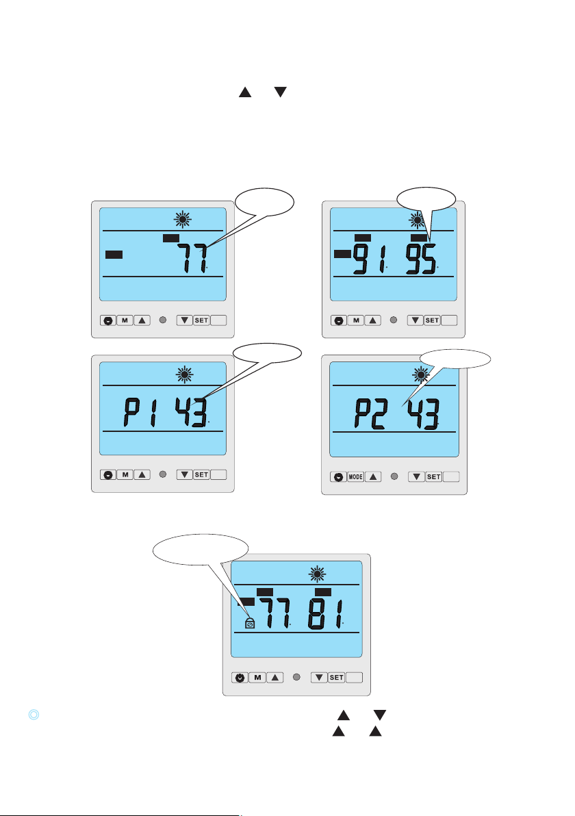
2.5 How to know current status
When heat pump is in running status, press and to check the current status of the unit. You can check
water-in / water-out temperature, condenser temperature and ambient temperature. Please note no press
on the controller for 5 seconds, controller will return to main interface, which displays water-in and
water-out temperature.
When heat pump is in standby status, controller will display only ambient temperature.
Remarks: Standby status means the unit is connected with electricity but not running .Parameter 00-10
can ONLY be changed under standby status!
2.6 Controller lock
TEMP
IN
AUX
Controller lock
OUT
AUX
ROOM
TEMP
IN
OUT
AUX
TEMP
AUX
Condenser 2 temp.
AUX
Regardless the heat pump is in running or standby status, press and at the same time for 3
seconds, all buttons will be locked and display as above. Press and for 3 seconds for unlocking.
F
F
F
F
F
F
F
Water temp.
Of inlet/outlet
Condenser 1 temp.
Ambient temp.
10
Preparation before startup
A) Inspection of the heat pump
- Check whether the outer appearance of the unit or pipeline system in the unit is damaged during transportation.
- Check whether the ventilator fan does not touch any part of the unit
.
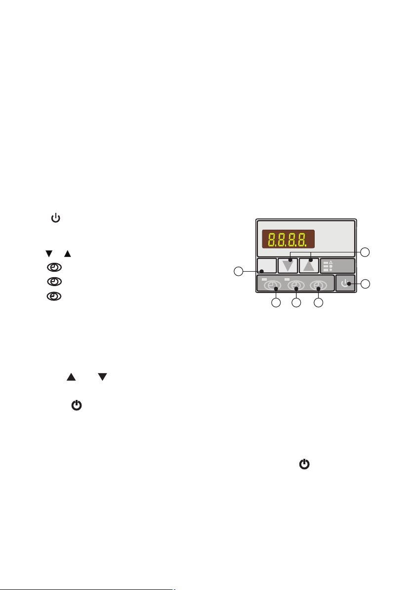
3.1 Illustration of controller
A. : Switch on or off heat pump.
MODE
B. : Select auto, heating or cooling mode.
Relevant indicator would be on when selected.
C. or : Press to change figures.
1
D. : Timer on setting button.
0
E. : Timer off setting button.
MODE
1
0
HEAT
COOL
AUTO
A
B
C
D
E
F
3. Control the heat pump (LED)
F. : Time setting button.
B) Verifying the electrical connections
- Check whether power supply complies with specifications in this manual or on the label placed on the unit.
- Check whether the power cabling is connected correctly and firm according to the wiring diagram.
Adequate grounding is required to protect against electrical shock.
3.2How to change desired temperature
1. Be sure that the heater is on Stand by mode.
2. Press “SET” button repeatedly until you see "01"
3. Use the and buttons to reach the desired temperature.
4.Once it is set, wait a few seconds for the screen revert to temperature display.
5. Push the button to start the heater.
Notes:
1. You cannot change the temperature while the heater is running (2 temperatures on
digital display= Running Mode)
2. You must put the heater on "Stand By" mode, by pressing the " " button on the
digital controller to change the temperature ( 1 temperature on digital display= Stand By mode)
3. If you wait too long, the screen will revert back to temperature display. Simply, press
the “SET” button again until you reach "01"
11
MODE
1
0
HEAT
COOL
AUTO
MODE
1
0
HEAT
COOL
AUTO
MODE
1
0
HEAT
COOL
AUTO
Auto mode
Heating mode
cooling mode
3.5 How to set desired water temperature.
1.First select desired mode, auto, heating or cooling.
2.No matter the heat pump is under standby status or running status, press or , display will
show the desired water temp. of selected mode with a flashing value, then change the water temp.
by moving or as requested.
12
MODE
1
0
HEAT
COOL
AUTO
Value of desired
water temp. under
cooling mode
MODE
1
0
HEAT
COOL
AUTO
Value of desired
water temp. under
heating mode
MODE
1
0
HEAT
COOL
AUTO
Value of desired
water temp. under
auto mode
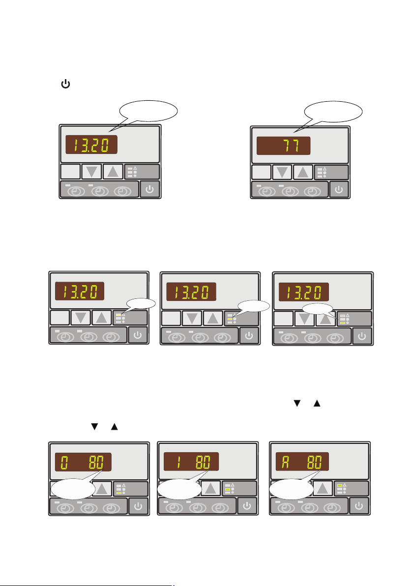
3.4 How to change mode
Press MODE button to select auto, heating or cooling mode, related indicator light on the right side of
controller will be on as a symbol.
MODE
1
0
HEAT
COOL
AUTO
Standby status
MODE
1
0
HEAT
COOL
AUTO
Running status
3.3 How to start heat pump
Connected with power, the controller will display the time. This means the unit is in standby.
Press to start the Heat pump. The controller display will show inlet water temperature now.
MODE
1
0
HEAT
COOL
AUTO
Ambient temp.
MODE
1
0
HEAT
COOL
AUTO
Actual inlet
water temp.
MODE
1
0
HEAT
COOL
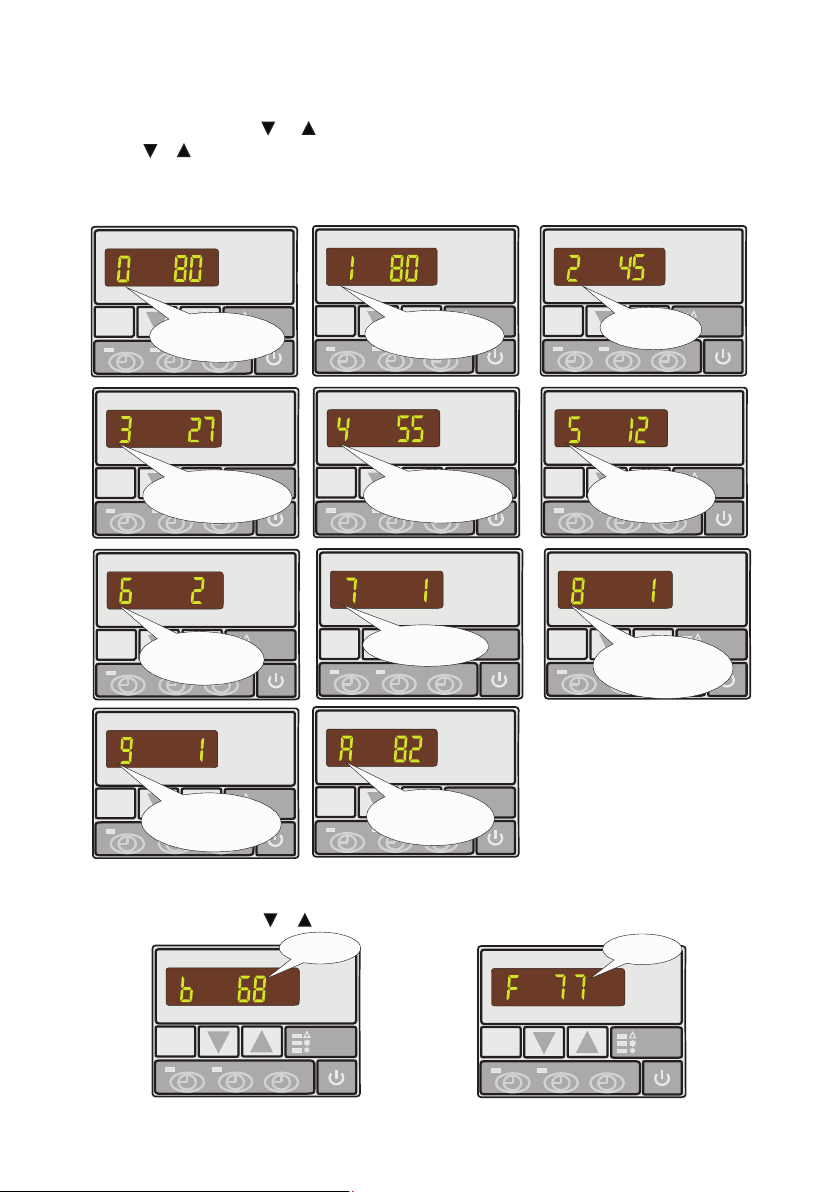
AUTO
Parameter 9
Water pump working mode:
0 water pump keeps working always
1 water pump works in accordance
with heat pump
MODE
1
0
HEAT
COOL
AUTO
Parameter A
Desired water temp. in
auto mode (46~104℉),
default setting:82℉
MODE
1
0
HEAT
COOL
AUTO
Parameter 8
Type of heat pump:
0 cooling only
1 cooling & heating
2 cooling & heating +elec. heating
3 heating only
MODE
1
0
HEAT
COOL
AUTO
Parameter 7
Restart after power failure
MODE
1
0
HEAT
COOL
AUTO
Parameter 6
Numbers of refrigerant
circuit
3.7 How to check parameter setting & measured values of current status
In standby or running status press or to find parameter 0-A and measured values of current status.
13
3.6 How to change parameter setting
1. In standby status press or to find parameter 0-A and measured values of current status B-F.
2. Press & at the same time for 5 seconds continuously to activate parameter setting.
3. Change value on setting until a BEEP is heard while display remains indicating parameter with its
value flashing.
4. No pressing the controller for 5s PCB will store data automatically and return to standby status.
MODE
1
0
HEAT
COOL
AUTO
Parameter 2
Defrosting cycle
MODE
1
0
HEAT
COOL
AUTO
Parameter 0
Desired water temp. in
cooling mode (46~82℉),
default setting:82℉
MODE
1
0
HEAT
COOL
AUTO
Parameter 1
Desired water temp. in
heating mode (59~104℉),
default setting:82℉
MODE
1
0
HEAT
COOL
AUTO
Parameter 5
Maximum duration for
defrosting 1-12min)
default setting:8 min
MODE
1
0
HEAT
COOL
AUTO
Parameter 4
Evaporator temp. set point
for stopping defrosting (36~86℉)
default setting:55℉
MODE
1
0
HEAT
COOL
AUTO
Parameter 3
Evaporator temp. set point
for starting defrosting (-22~32℉)
default setting:27℉
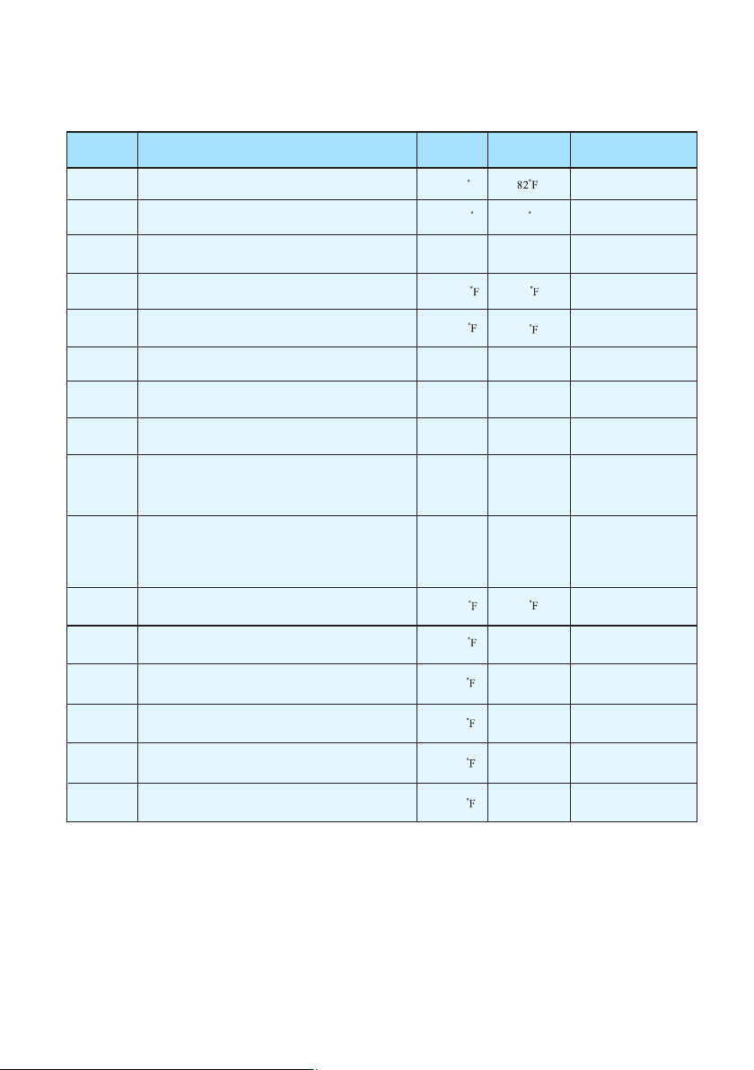
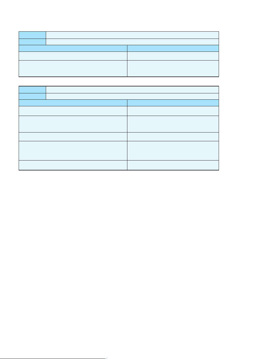
Parameter
Definition
Range
Default Remark
0
1
2
3
4
5
6
7
8
9
Desired water temperature in cooling mode
Desired water temperature in heating mode
Defrosting cycle
Evaporator temperature set point for stopping defrosting
Maximum duration for defrosting
Number of compressor in the system
Restart after power failure
Type: Cooling only 0/
Heating &cooling 1/
Heating & cooling + Auxiliary heating 2/
Heating only 3/
Different working mode of water pump:
water pump keeps working always 0/
water pump works in accordance
with heat pump 1 /
46~82 F
59~99 F
30~90Min
-22~32
37~86
1~12Min
1~2
0~1
0~3
0~1
82 F
40Min
27
55
8Min
1(Yes)
3
0
Ajusted
by Technicians
Ajusted
by Technicians
Ajusted
by Technicians
Ajusted
by Technicians
Ajusted
by Technicians
Ajusted
by Technicians
Ajusted
by Technicians
Ajusted
by Technicians
Ajusted
by Technicians
Ajusted
by Technicians
A
B
C
D
E
F
Desired water temperature in auto mode
Actual inlet water temp.
Actual outlet water temp.
Coil temp. in system 1
Ambient temp.
46~99 82
Ajusted
by Technicians
16~99
16~99
Measured Value
Measured Value
Measured Value
Measured Value
Coil temp. in system 2
Measured Value
Evaporator temperature set point for starting defrosting
1
Parameter table overview
14
16~99
16~99
16~99
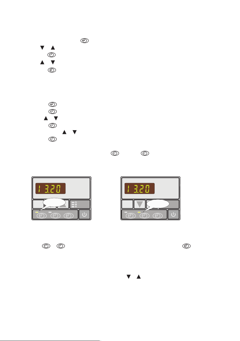
3.9 How to set timer on and timer off
a) Press to activate timer on setting, hour and minute figures will be flashing together.
b) Press again to have active hour setting, hour figure will be flashing and ready to be modified
by or .
c) Press again to have active minute setting, minute figure will be flashing and ready to be
modified by or .
d) Press to confirm the setting and display will return to standby status. Timer on indicator
green light would be on as a symbol.
e) Operate the same to timer off by using instead of . timer off indicator red light would be
on as a symbol.
Note: Timer on and timer off can be selected both or separately.
1
1
1
1
0 1
3.8 How to set clock
1. In standby status press button, hour figures will be flashing and ready to be modified
by or .
2. Press button for second time, minute figures will be flashing and ready to be modified
by or .
3. Press button for final confirmation of time setting.
After the time is set LED display will show time when the heat pump is under standby status.
3.10 How to cancel timer on and timer off
10
Press or to activate, relative indicator light would be flashing, press for cancellation
of timer on or timer off.
3.11 Keypad lock and unlock
Except parameter setting, in other situation press & at the same for 3 s, keypad would be locked
after BEEP . To unlock it please press both buttons together again for another 3 s.
MODE
1
0
HEAT
COOL
AUTO
MODE
1
0
HEAT
COOL
AUTO
TIMER ON
indicator
TIMER OFF
indicator
15

4. Protection systems
4.1 Water flow switch
Equipped with flow switch the heat pump will not work when the filter pump is not working (and the
water is not circulating).
This system prevents the heat pump from heating only the water present in the heat pump itself.
The protection also stops the heat pump if water circulation is cut off or stopped.
4.2 Refrigerant gas high and low pressure protection
The high pressure protection makes sure the heat pump is not damaged in case of over pressurisation of
the gas. The low pressure protection emits a signal when refrigerant is escaping from the conduits and the
unit can not be kept running.
4.3 Automatic defrost control
When the air is very humid and cold, ice can form on the evaporator. In that event, a thin layer of ice
appears that will grow increasingly bigger as long as the heat pump is running. When the temperature of
the evaporator has become too low, automatic defrost control will be activated, which will reverse the
heat pump cycle so that hot refrigerant gas is sent through the evaporator during a brief period of time to
defrost it.
4.4 Temperature difference between inflowing and outflowing water
During normal operation of the heat pump, the temperature difference between inflowing and outflowing
water will approximate 18 to 36 .In the event that the pressure switch does not work and that the water
stops circulating, the temperature probe monitoring the outflowing water will always detect a rise in
temperature. As soon as the temperature difference between inflowing and outflowing water exceeds 23.4
the heat pump will be automatically turned off.
4.5 Low temperature cut-out
If, during cooling, the temperature of the outflowing water reaches 41 or drops below this temperature,
the heat pump will turn itself off until the water temperature reaches or exceeds 45 again.
4.6 Anti-frost protection during winter
This protection can only be activated if the heat pump is in STAND-BY status.
16
4.7 First anti-frost protection
If the filter pump is controlled by the heat pump (regardless of the value for parameter 9) and when the
water temperature lies between 36 and 39 ,and the air temperature is lower than .32 ,the filter pump will
be automatically turned on to prevent the water from freezing in the piping. This protection is deactivated
when the temperature rises again.
4.8 Second anti-frost protection
If the water temperature drops even more, that is, below 36 (during long frost periods), the heat pump
will also start running to heat the water until its temperature approximates 39 . When this temperature
is reached, the heat pump will stop, but anti-frost protection will remain active until conditions change.

17
5. Direction
5.1 Swimming pool water chemistry
pH
Free chlorine(mg/1)
TAC(mg/1)
Salt(g/1)
Important: failure to comply with these limits will invalidate the warranty.
Note: exceeding one or several limits can damage the heat pump beyond repair. Always install water
treatment equipment past the heat pump's water outlet, especially if the chemicals are automatically
added to the water.
A check-valve should also be installed between the outlet of the heat pump and this equipment in
order to prevent products from flowing back into the heat pump if the filter pump stops.
Special attention should be paid to the chemical balance of the pool water. The pool water values should
always stay within the following limits:
Min
7.0
0.5
80
Max
7.4
1.2
120
3
5.2 Heat pump winterizing
Important: failure to take the necessary precautions for winterizing can damage the heat pump,
which will invalidate the warranty.
The heat pump, filter pump, filter and conduits must be protected in areas where the temperature can drop
below the freezing point, Evacuate all water from the heat pump as follows:
1. Interrupt the electrical power supply to the heat pump
2. Close the water supply to the heat pump: completely close valves 2 and 3 of the by-pass
3. Disconnect the water inlet and outlet coupler fittings of the heat pump and let the water drain out of the
unit
5.3 Restarting the pump after winter
If you purged your heat pump for winterizing, you should undertake the following steps to restart it in spring:
1. Check first if there is no dirt in the conduits and if there are no structural problems
2. Check if the water inlet and outlet coupler fittings are adequately fastened to the heat pump
3. Start the filter pump to start the water flow to the heat pump. Set the by-pass again.
4. Reconnect the electrical power supply to the heat pump and turn it ON.
4. Loosely reattach water inlet and outlet coupler fittings to the heat pump in order to prevent dirt
from setting into the conduits.
Note: these precautions should not be taken if you choose to use the built-in anti-frost protection.

18
Condensation can occur when the heat pump is running. This condensation can flow away through an opening
in the base pan of the unit. The amount of condensation water will increase when atmospheric humidity is
high. Remove any dirt that could possibly hamper the evacuation of condensation.
10 to 20 litres of condensation water can be produced while the unit is running. If more condensation is
produced, stop the heat pump and wait for one hour before checking for leaks in the conduits.
Note: a quick way to verify that the water running through the condensation drain is indeed
condensation, is to shut off the unit and keep the pool pump running. If the water stops running out
of the condensation drain, it is condensation. AN EVEN QUICKER WAY is to TEST THE DRAIN
WATER FOR CHLORINE. If no chlorine is detected, the drain water is a result of condensation.
Also take care to leave air inlet and exhaust passages free. Prevent exhaust air from immediately re-entering
the unit through the inlet.
5.4 Check-up
Our heat pumps have been developed and built to last, that is, if they have been installed correctly and can
run under normal conditions. Regular check-ups are important if you want your heat pump to function
safely and efficiently for years on end.
1. Make for easy access to the service panel.
2. Keep the area surrounding the heat pump free of contingent organic waste.
3. Prune the vegetation near the heat pump so that there is enough free space around the pump.
4. Remove contingent water sprinklers from the vicinity of the heat pump. They can damage the heat pump.
5. Prevent rain from directly running off a roof onto the heat pump. Install proper drainage.
6. Do not use the heat pump if it has been flooded. Immediately contact a qualified technician to inspect
the heat pump and repair it if should prove necessary.

19
6. Maintenance and inspection
6.1 Maintenance
Check the water inlet and drainage often. The water and air inflow into the system should be sufficient
so that its performance and reliability does not get compromised. You should clean the pool filter
regularly to avoid damage to the unit caused by clogging of the filter.
The area around the unit should be spacious and well ventilated. Clean the sides of the heat pump
regularly to maintain good heat exchange and to save energy.
Check if all processes in the unit are operational and pay special attention to the operation perssure of
the refrigerant system.
Check the power supply and cable connections regularly. Should the unit begin to function abnormally
or should you notice a smell from an electrical component, arrange fro timely repair or replacement.
You should also purge the water if the unit will not work for an extended period of time. You should
check all parts of the unit thoroughly and completely fill the system with water before turning it on
again afterwards.
Improper installation may result in an electrical discharge that could lead to death of-or serious injury
to-pool users, installers or others due to electrical shock and may also cause damage to property.
DO NOT attempt to modify the internal configuration of the heat pump.
1. Keep your hands and hair clear of the fan blades to avoid injury.
2. If you are not familiar with your pool filtering systems and heat pump:
a. Do not attempt to adjust or service without consulting your dealer or your professional pool or air
conditioning contractor.
b. Read the entire installation and user manual before attempting to use, service or adjust the unit.
C. Start the heat pump at least 24 hours after its installation in order to prevent damage to the compressor.
6.2 Trouble shooting guide
Note: Switch off the power prior to maintenance or repairs.
IMPORTANT REMARK: if a malfunction can not be resolved immediately, in order to analyse the
problem itself, we will need to know the message(error code) that is displayed on the controller, as
well as the values for the settings (parameter 00-10 for LCD display while parameter 0-A for LED
display) and for status of the heat pump (a mbient te mpe rature, w ater inle t/ outlet tem per atu re
and system coil temperature) just before the failure or, if this is impossible, just after it.
Please keep this information at hand when calling customer service.
On the following pages, you will find an overview of the different types of failure problems that can occur,
along with directions to solve them.
20
Problem:
Observation:
Possible cause
Solution
the heat pump works normally but there is no or insufficient heating
The screen displays the temperature but no error codes
1. In sufficient capacity of the heat pump in proportion to the
size of the swimming pool
2. The compressor works but the fan doesn't
3. The fan works but the compressor doesn't
4. The heat pump has not been placed on an optimal location
5. Faulty temperature setting
6. By-pass not adjusted
7. Massive ice formation on the evaporator
8. Not enough refrigerant
1. Install a larger sized model or an extra heat pump.
Cover the pool to limit heat loss
2. Check the electrical wiring of the fan. Replace the
condenser or the fan motor if necessary.
3. Check the electrical wiring of the compressor.
Replace the condenser or the compressor if necessary.
4. Make for sufficient air circulation(see manual for
details)
5. Set the correct temperature
6. Have the by-pass readjusted by the installer
7. Have the settings for automatic defrost control
checked by the installer
8. Have the heat pump checked by a refrigeration
technician
Problem:
the heat pump doesn't work
Observation:
the screen does not light up and the fan/compressor doesn't make a sound
Possible cause
No electrical power supply
Solution
Check power supply (wiring, fuses,…… ……)
Problem:
the heat pump doesn't stop
Observation:
the screen displays the temperature but no error codes
Possible cause
Solution
1. Wrong setting of parameters
2. Pressure switch out of order
3. Electrical failure
1. Check the set parameters and adjust them if necessary
(settings just above the capacity of the heat pump)
2. Check operation of the pressure switch by turning
off the filter pump and restarting it. If the heat pump
doesn't react to this, the pressure switch must be
adjusted or replaced.
3. Contact your installer
The heat pump works normally but the water is cooling down instead of heating up
The screen displays the temperature but no error codes
Problem:
Observation:
Possible cause
Solution
1. The wrong mode has been selected
2. The controller is out of order
3. The 4-way valve is out of order
1. Verify the parameters, select the correct mode
2. Check the voltage in the electrical wiring to the
4-way valve. If no electric potential is measured,
replace the controller
3. Check the voltage in the electrical wiring to the
4-way valve. If electric potential is measured,
replace the coil. If the problem persists, have the
heat pump checked by a refrigeration technician
21
Problem:
Observation:
Possible cause
Solution
abnormal amount of ice formed on the evaporator
the evaporator is for the most part covered in ice
1. Insufficient air inflow
2. High water temperature
3. Incorrect setting of automatic defrost control
4. The 4-way valve is out of order
5. Not enough refrigerant
1. Check the location of the heat pump and remove any
dirt that could be present on the evaporator
2. If the pool water is already quite hot (warmer than
29?),the probability of ice formation increases.
Lowering the set temperature is a possible option
3. Check the setting of the defrosting function together
with your installer.
4. Check the voltage in the electrical wiring to the 4
-way valve. If electric potential is measured, replace
the coil. If the problem persists, have the heat pump
checked by a refrigeration technician.
5. Have the heat pump checked by a refrigeration
technician.
Problem:
Observation:
Possible cause
Solution
water leak
there's an amount of water under the heat pump
1. Condensation due to atmospheric humidity
2. Water leak
1. No action required
2. Try to localize the leak and check for the presence
of chlorine in the water. If that is the case, the heat
pump must be temporarily replaced during repair.
22
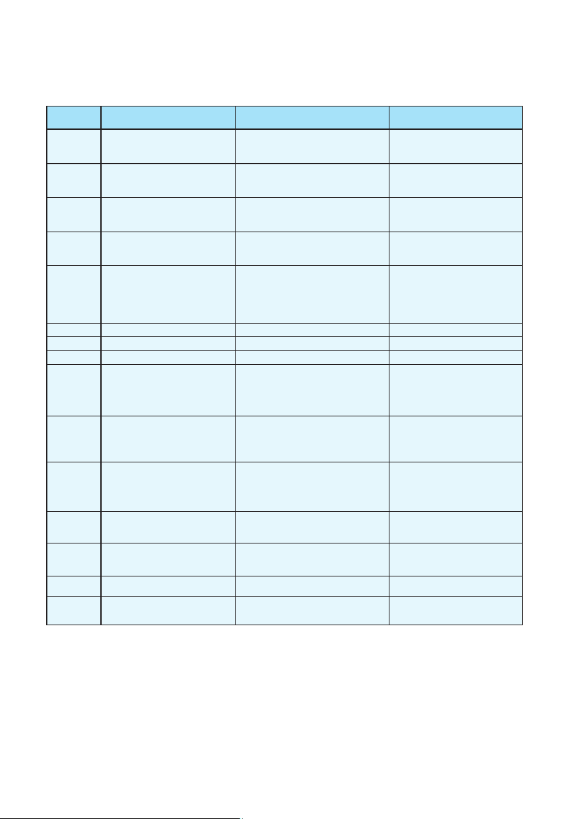
Protection/Failure
Wire
controller
PP07/PP7
PP07/PP7
EE05/EE5
No display
EE08/EE8
Check Solution
PP01/PP1
1. Check the connection of inlet water
sensor.
2. Check if the sensor is broken.
1. Reconnect the sensor.
2. Replace the sensor.
PP02/PP2
1. Check the connection of outlet water
sensor.
2. Check if the sensor is broken.
1. Reconnect the sensor.
2. Replace the sensor.
PP03/PP3
1. Check the connection of coil
temperature sensor.
2. Check if the sensor is broken.
1. Reconnect the sensor.
2. Replace the sensor.
PP05/PP5
1. Check the connection of ambient
temperature sensor.
2. Check if the sensor is broken.
1. Reconnect the sensor.
2. Replace the sensor.
PP06/PP6
1. Check if there is any jam in the water
circuit.
2. Check if the water flow volume is enough.
3. Check if the water pump has failed to
work.
1. Remove the jam.
2. Increase the water flow volume.
3. Repair or replace the water pump.
Refer to PP06. Refer to PP06.
EE03/EE3
1. Check if wiring connection of flow
switch is in position.
2. Check if enough water flow.
3. Check if flow switch is broken.
4. Check if water pump failure.
1. Reconnect the wiring.
2. Increase enough waterflow.
3. Replace flow switch.
4. Repair or replace water pump.
1. Check if there is enough water flow volume.
2. Check if inlet / outlet water temp. sensor
failure.
1. Adjust bigger water flow.
2. Replace related sensor.
Check the connection
Reconnect the connection wire.
PP07/PP7
No action required
No action required
Winter anti-freeze protection Ⅰ
Water flow switch failure
Protection for over-big temp.
Difference between water inlet &
outlet
Ambient temp. sensor failure
Coil temp. sensor failure
Outlet water temp. sensor failure
Inlet water temp. sensor failure
Failure of over-big temp.
difference between water
inlet & outlet
Defrosting
Communication failure
Winter anti-freeze protection Ⅱ
Anti-freeze protection for cooling
6.3 Failure code table for single-system
EE04/EE4
Order of phases incorrect
(only for 3 phase model)
Order of phases incorrect
Reconnect the phases in right order.
EE01/EE1
High pressure protection
EE06/EE6
1. Check if high pressure switch is broken
2. Check if there is a blockage in water
circuit or water flow is not enough.
3. Check if there is a blockage in refrigerant
circuit.
1. Replace high pressure switch.
3. Remove cause of blockage or
increase water flow.
4. Send heat pump to dealer for detailed
check.
1. Check if low pressure switch is broken.
2. Check if refrigerant level is low.
3. Ambient temp. and water inlet
temp. is too low.
1. Replace low pressure switch.
2. Fill up with enough refrigerant.
3. Decrease water flow.
4. Send heat pump to dealer for
detailed check.
Low pressure protection
23
6.4 Failure code table for double-system
Protection/Failure
Wire
controller
EE03/EE3
No display
Check Solution
PP01/PP1
1. Check the connection of inlet water
sensor.
2. Check if the sensor is broken.
1. Reconnect the sensor.
2. Replace the sensor.
PP02/PP2
1. Check the connection of outlet water
sensor.
2. Check if the sensor is broken.
1. Reconnect the sensor.
2. Replace the sensor.
PP03/PP3
1. Check the connection of coil 1
temperature sensor.
2. Check if the sensor is broken.
1. Reconnect the sensor.
2. Replace the sensor.
PP04/PP4
1. Check the connection of coil 2
temperature sensor.
2. Check if the sensor is broken.
1. Reconnect the sensor.
2. Replace the sensor.
PP05/PP5
1. Check the connection of ambient
temperature sensor.
2. Check if the sensor is broken.
1. Reconnect the sensor.
2. Replace the sensor.
1. Check if there is any jam in the water circuit.
2. Check if the water flow volume is enough.
3. Check if the water pump has failed to work.
PP06/PP6
1. Remove the jam.
2. Increase the water flow volume.
3. Repair or replace the water pump.
PP07/PP7
Refer to PP06. Refer to PP06.
1. Check if wiring connection of flow
switch is in position.
2. Check if enough water flow.
3. Check if flow switch is broken.
4. Check if water pump failure.
1. Reconnect the wiring.
2. Increase enough water flow.
3. Replace flow switch.
4. Repair or replace water pump.
EE04/EE4
1. Check if high or low pressure switch is
broken.
2. Check if lack of refrigerant.
(For low pressure)
3. Ambient temp. and water inlet temp. is
too low. (For low pressure)
4. Check if there's jam in water circuit or
water flow not enough. (For high pressure)
5. Check if refrigerant circuit jam.
(For high pressure)
1. Replace new pressure switch.
2. Charge enough refrigerant.
3. Adjust less water flow.
4. Remove jam or adjust bigger
water flow.
5. Send heat pump to dealer for
detailed check.
EE05/EE5
1. Check if there is enough water flow
volume.
2. Check if inlet / outlet water temp. sensor
failure.
1. Adjust bigger water flow.
2. Replace related sensor.
EE08/EE8
Check the connection
Reconnect the connection wire.
PP07/PP7
No action required
Water flow switch failure
Defrosting
Inlet water temp. sensor failure
Outlet water temp. sensor failure
Coil 1 temp. sensor failure
Coil 2 temp. sensor failure
Ambient temp. sensor failure
Protection for over-big temp.
difference between water
inlet & outlet
Anti-freeze protection for cooling
Wrong phase or lack of phase
Failure of over-big temp.
difference between water
inlet & outlet
Communication failure
Winter anti-freeze protection Ⅰ
Winter anti-freeze protection Ⅱ
PP07/PP7
No action required
EE01/EE1
EE07/EE7
High pressure in system 1
EE06/EE6
EE02/EE2
High pressure in system 2
Low pressure in system1
Low pressure in system2
1. Replace high pressure switch.
3. Remove cause of blockage or
increase water flow.
4. Send heat pump to dealer for detailed
check.
1. Check if low pressure switch is broken.
1. Check if low pressure switch is broken.
2. Check if refrigerant level is low.
3. Ambient temp. and water inlet
temp. is too low.
1. Replace low pressure switch.
2. Fill up with enough refrigerant.
3. Decrease water flow.
4. Send heat pump to dealer for
detailed check.
1. Check if high pressure switch is broken
1. Check if high pressure switch is broken
2. Check if there is a blockage in water
circuit or water flow is not enough.
3. Check if there is a blockage in refrigerant
circuit.
24
7.Name plate & wiring diagram
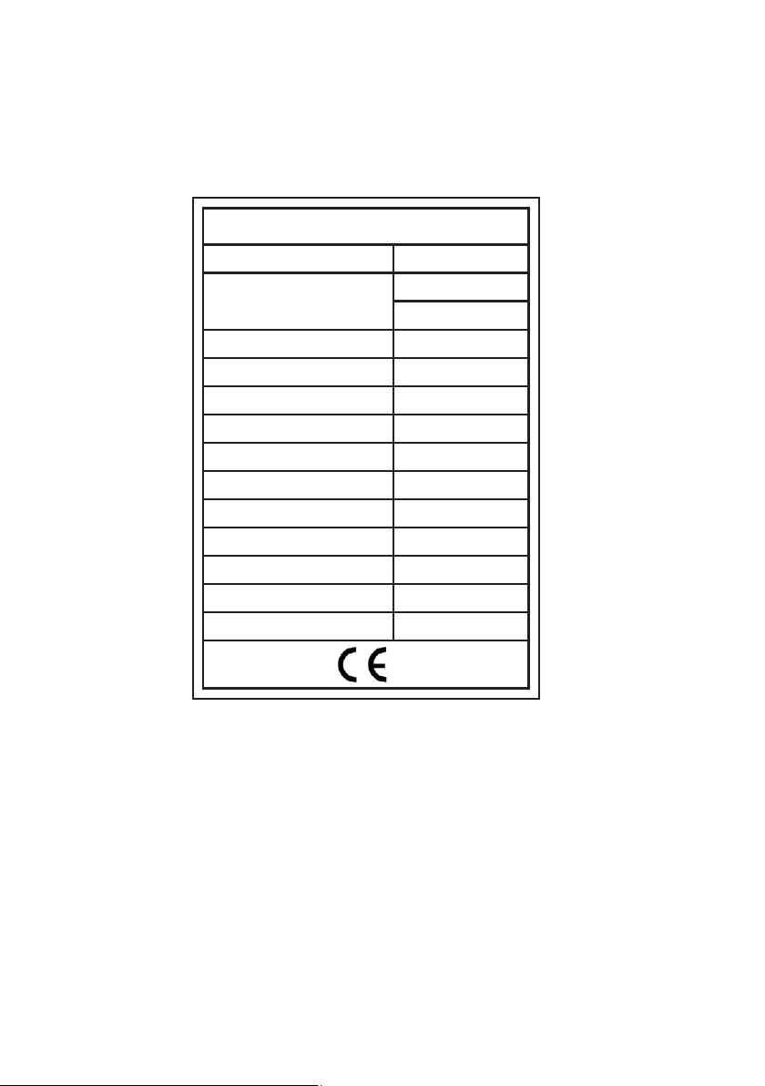
7.1Name plate
Unit Model
Input Power Heating
Running Current Heating
Power Supply
Input Power Of Fan
Fan Rotate Speed
Noise
Water Connection
Water Flow Volume
Water Pressure Drop
Refrigerant(R410A)
Net Weight
FH-055
16000W
55000BTU/h
2350W
11.2A
208~230V/1PH/60Hz
120W
900RPM
55dB(A)
50mm
3
4-7m /h
20Kpa
1200g
57kg
Rated Heating Capacity
SWIMMING POOL HEATER
25
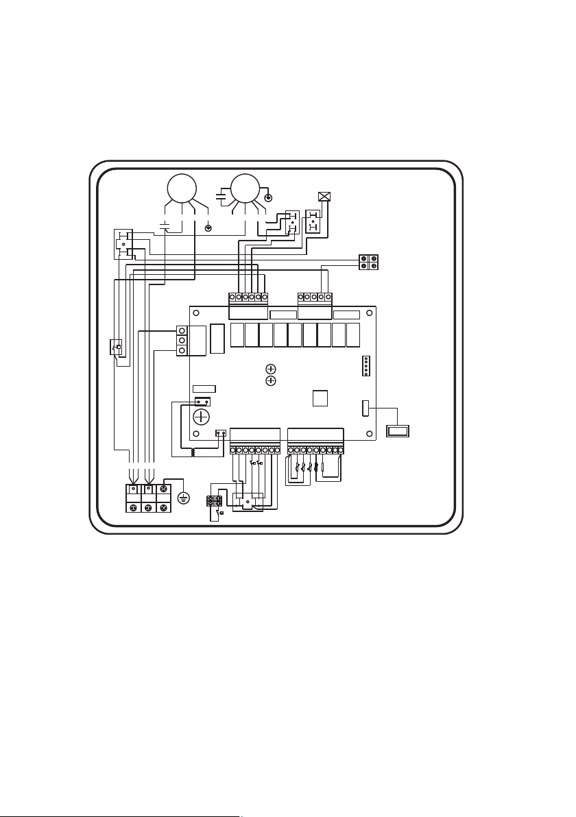
7.2 Wiring diagram
KA9/5AKA8/5AKA7/5AKA 6/5AKA5/5AKA4/5AKA3/5AKA 2/5 AK A1/ 5A
AC-L
AC-L
AC-N
AC-L
L1
L2
RED
BLU
POWER SUPPLY
220V/AC
12V/AC
Transformer
Y/G
REDBLU
BLK
C
C
R
S
CM
I<1.5A
water pump
T1:
T2:
T3:
T4:
Ambient temp
Coil temp
Outlet water temp
Wire controller
PP
A1
A2
L2
Low Pressure switch
High Pressure switch
K1:
K2:
L1
L2
B01
Y01
GND
FUSE
FUSE
FUSE
L1
L1
30
CM: Compressor
FM: Fan
KM: AC contactor
K3:
Water flow switch
32
28 29
Inlet water temp
P
G
G
L2
1104-1717
NOTE:
For current of water pump
above 1.5Amp.
please externally equip
suitable A/C contactor.
ORG
BLU
C
BLKWHI
RED
FM
4-way valve
A
B
YEL
HF
LF
G
KM
K3
K2
K1
1108
T1 T2 T3 T4
R=5K
GND
GND
GND
IC
CC395-V1.0
07
10
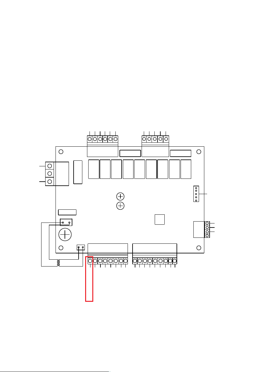
KA9/ 5AKA8/ 5AKA7/ 5AKA6/ 5AKA5/ 5AKA4/ 5AKA3/5AKA2/5AKA1/5A
CC395-V1.0
AC- N
AC- L
220V/AC
12V/ AC
Transformer
COM
EEV
Crank shaft electrical
heating
High fan spped
Low fan spped
1#Four-way valve
1#Compressor
AC-L
2#Four-way valve
2#Compressor
Bottom heater
Circulating water pump
AC-L
IC
Emergency switch
Phase sequence switch
Water flow switch
1#High pressure gauge
1#Low pressure valve
2#High pressure gauge
2#Low pressure valve
GND
GND
Ambient temperature
Inlet water temperature
Outlet water temperature
1#Coil temperature
2#Coil temperature
Reserved
Reserved
GND
AQUALINK CONNECTION IS DONE BY INTERRUPTING THE EMERGENCY
SWITCH WIRE. AQUALINK RELAY SHOULD BE INSTALLED AS ON / OFF
SWITCH FOR THIS WIRE.
26
27
FIBROHEAT HEAT PUMP LIMITED FACTORY WARRANTY
Fibropool Co.LLC warrants this Pool/Spa Heat Pump, to the original owner, to be free of material and workmanship defects for a limited TEN(10) year term.
Heat pumps utilizing Fibropool Titanium Heat Exchangers carry a lifetime warranty on the titanium tubing.
Specific warranty term are listed below. This warranty will begin on the homeowner’s proof of purchase documents.
The full warranty term includes parts and labor charges to remove, repair or replace defective components or failure due to workmanship.
CLAIMS FOR WARRANTY REIMBURSEMENT MUST HAVE PRIOR AUTHORIZATION BY FIBROPOOL and be performed be a Factory Authorized Service Center.
This warranty dose not include transportation changes for equipment parts to and from the factory. overed by this warranty.
Note 3: Seasonal warranty begins on the date of purchase and ends on Dec 31st of the same year.
Note 4: Scuff, rip, tear and overexposure to ultraviolet rays is not covered by this warranty.
This warranty is applicable only if the unit’s installation and operation is expressly and completely followed in accordance with the purchased model’s Owner/ Installation manual.
These documents are furnished with each unit and are available by contacting the Fibropool Co.LLC.
The liability of Fibropool Co.LLC shall not exceed the repair or the replacement of defective parts under the referenced year exclusion, ten (10) year
limited term and shall not include consumables, including refrigerant or transportation to or from the Fibropool Service Center. Fibripool Co. LLC is
not liable for any damages of any sort whatsoever, including incidental and consequential.
PROOF OF PURCHASE REQUIRED FOR WARRANTY COVERAGE
Warranty Schedule
Lifetime warranty on titanium tubing heat exchanger
1 year labor on the entire unit
2 years full on compressor, cabinet and digital display
3-10 years prorated warranty on the compressor, cabinet and digital display
5 years full warranty on all other parts
6-10 years prorated warranty on all other parts
This warranty does not include damage to any internal piping components due to freezing conditions, negligence and abuse,
installations in corrosive environments or atmospheres nor acts of God.
There are no implied warranties of merchantability of fitness for a particular purpose that apply to this product.
PLEASE RETAIN THE UPPER PORTION OF THHIS SHEET AND MAIL THE BOTTOM PORTION TO: Fibropool LLC.
PO Box 2425, Bay Saint Louis, MS 39520 USA
Toll free: 1-877 342 7676 Fax: +1-201 328 3300 Email: support@fibropool.com
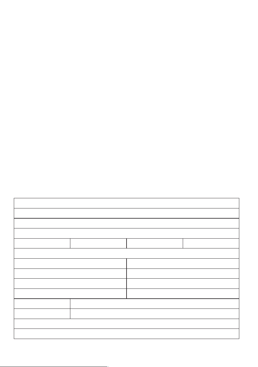
Customer Name
Address
City
State/Province Zip/Post code
Country
Email Address Phone Number
Item Purchased
Serial Number (if applicable)
Date of Purchase Dealer/Retailer
Installer name/contact information (if other than customer/homeowner)