
N
L
IN CASE OF ANY QUERY/ISSUE WITH THE PRODUCT, PLEASE REACH OUT TO US AT: SUPPORT@V-TAC.EU
FOR MORE PRODUCTS RANGE, INQUIRY PLEASE CONTACT OUR DISTRIBUTOR OR NEAREST
DEALERS. V-TAC EUROPE LTD. BULGARIA, PLOVDIV 4000, BUL.L.KARAVELOW 9B
CAUTION:
EMERGENCY WIRING DIAGRAM:
1. Battery is in an empty state, please ensure to charge more than
36hours before using.
2. Power connected but light does not work, please check whether
the light is properly connected to the mains.
3. Please strictly use the emergency kit according to the wiring
diagram before connection and pay attention to reverse connection.
Ni-Cd 9.6V2200mAh
SINGLE UNIT INSTALLATION INSTRUCTIONS
STEP 7: Wire the water-
proof fitting to the main
power supply. Ensure to
use waterproof terminal
block [not included].
STEP 6: Install the diffuser
to the waterproof fitting
and close the clips.
STEP 4: Open
the side clips of
waterproof fitting
and open the
diffuser as shown
in the diagram.
STEP 2: Fix the mounting
brackets onto the ceiling
using screws and expansion
plug(included). Please refer
to table 1 for installing the
mounting bracket distance
points.
STEP 3: Mount water-
proof lamp onto the
mounting brackets.
MULTIPLE (LINKABLE) UNITS INSTALLATION INSTRUCTIONS
L1
STEP 1: Switch
OFF the power
before starting
the installation.
OFF
STEP 8:
Switch ON
the power
to test the
light.
ON
STEP 8: Wire the waterproof
fitting to the main power supply.
Ensure to use waterproof terminal
block [not included].
STEP 9: Switch ON the power to
test the light.
STEP 7: Install the diffuser to the waterproof
fitting and close the clips.
STEP 5: Wiring 1st waterproof fitting from both
the ends - Fasten the waterproof connector
clockwise from the first end and insert the cable
through the waterproof connector and wire into
the terminal block from one end.
Note: For Maintained and Non-Maintained wiring
please refer to the wiring diagram.
WATERPROOF
END WIRE
STEP 6: Fasten the waterproof
connector from other end of the
waterproof fitting and insert the
wire into the terminal block.
Using the same cable fasten
the waterproof connector of the
2nd waterproof fitting and wire
into the terminal block.
L
N
L
LS
N
STEP 4: Open
the side clips of
waterproof fitting
and open the
diffuser as shown
in the diagram.
STEP 2: Fix the mounting
brackets onto the ceiling
using screws and expansion
plug(included). Please refer
to table 1 for installing the
mounting bracket distance
points.
Note: Please refer to the model number and max linkable units which can be linked together. Based on the max linkable
units select the max waterproof fittings which you would like to connect.
STEP 3: Mount water-
proof lamp onto the
mounting brackets.
L1
STEP 1: Switch
OFF the power
before starting
the installation.
OFF
LS
WATERPROOF CONNECTOR
L
LS
N
L
LS
N
STEP 5: Fasten the waterproof connector
clockwise. Insert the cable through the
waterproof connector and wire it into the
terminal block.
Note: For Maintained and Non-Maintained
wiring please refer to the wiring diagram.
N
LS
L
N
LS
L
N
L
WATERPROOF CONNECTOR
L
LS
N
L
LS
N
Blue
Blue
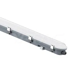
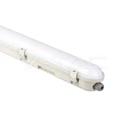
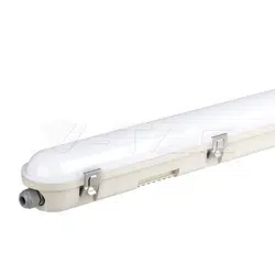
LED WATERPROOF FITTINGS (MILKY COVER) WITH EMERGENCY KIT
TECHNICAL DATA:
INTRODUCTION & WARRANTY
WARNING!
1. Please make sure to turn off the power before starting the installation.
2. Installation must be performed by a qualified electrician.
3. The light source of this luminaire is not replaceable, when the light source reaches its end of life the whole luminaire
should be replaced.
4. If the external flexible cable or cord of this luminaire is damaged, it shall be exclusively replaced by the manufacturer
or his service agent or a similar qualified person in order to avoid a hazard.
5. The luminaire is designed with an emergency kit with a replaceable battery. If the battery no longer meets their rated
duration of operation after corresponding recharge period the battery/emergency kit should be replaced by the
manufacturer or his service agent or a similar qualified person in order to avoid a hazard.
3
YEARS
WARRANTY
*
IP65
RATING
Caution, risk of electric shock.
This marking indicates that this
product should not be disposed
of with other household wastes.
MODEL WATTS LUMENS CRI DF
BEAM
ANGLE
DIMENSION INPUT POWER
L1
MAX
CONNECTABLE
UNITS
10 UNITS
830+40mm
VT-120036E 36W 4320LM >80 >0.9 120° 1200x72x78mm AC: 200-240V, 50/60Hz
8 UNITS
1090+40mm
VT-150048E 48W 5760LM >80 >0.9 120° 1500x72x78mm AC: 200-240V, 50/60Hz
Non-replaceable
light source
Non-replaceable
control gear
20
PAP
TECHNICAL DATA: EMERGENCY KIT
EMERGENCY
POWER
BATTERY TYPE
CHARGING TIME
WORKING TIME
CHARGE
RECHARGE
AMBIENT
TEMPERATURE (ta)
6-7W
9.6V 2200mAh Ni-Cd ba�ery
24 Hours
3 Hours
0-50°C
500 TIMES
Thank you for selecting and buying V-TAC product. V-TAC will serve you the best. Please read these instructions
carefully before starting the installation and keep this manual handy for future reference. If you have any another
query, please contact our dealer or local vendor from whom you have purchased the product. They are trained and
ready to serve you at the best. The warranty is valid for 3 years from the date of purchase. The warranty does not
apply to damage caused by incorrect installation or abnormal wear and tear. The company gives no warranty against
damage to any surface due to incorrect removal and installation of the product. The products are suitable for 10-12
Hours Daily operation. Usage of product for 24 Hours a day would void the warranty. This product is warranted for
manufacturing defects only.
MULTI-LANGUAGE
MANUAL QR CODE
Please scan the QR code
to access the manual in
multiple languages.