Loading ...
Loading ...
Loading ...

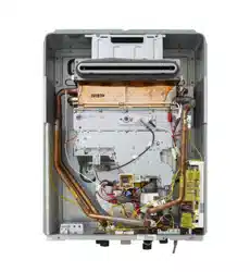
Rinnai 20 HW_CF OIM
APPLIANCE FLUE TERMINAL
+RUL]RQWDO7HUPLQDO&OHDUDQFHV([WUDFWIURP$61=6
Min. Clearances
(mm)
For appliances up to 50 MJ/h input
200
For appliances over 50 MJ/h input
300
300* ecafrus rehto ro ynoclab a evoba ,dnuorg eht morFb
300* renroc lanretxe ro llaw nruter a tnor
Fc
d
From a gas meter (M) (see Note 5)
(see Clause 5.11.5.9 for vent terminal location of regulator)
(see Table 6.7 for New Zealand requirements)
1000
e
From an electricity meter or fuse box (P) † (see Note 5)
500
epip lios ro epip niard a morFf
g
Horizontally from any building structure* = or obstruction facing a terminal
500
h
From any other flue terminal , cowl, or combustion air intake *
300
Appliances up to 150 MJ/h input *
300
Appliances over 150 MJ/h input up to 200 MJ/h input *
300
Appliances over 200 MJ/h input up to 250 MJ/h input *
500
Appliances over 250 MJ/h input *
1500
All fan-assisted flue appliances, in the direction of discharge
1500
1000rewolb aps a gnidulcni ,telni r
ia lacinahcem a morFk
Space heaters up to 50 MJ/hr input
Other appliances up to 50 MJ/hr input
500
Appliances over 50 MJ/h input and up to 150 MJ/h input
1000
Appliances over 150 MJ/h input
1500
metI.feR
a
Below eaves, balconies and other projections:
FIGURE 6.2 (in-part) LOCATION OF FLUE TERMINALS OF BALANCED FLUE,
ROOM-SEALED, FAN-ASSISTED OR OUTDOOR APPLIANCES
n
j
Horizontally from an openable window, door, non-mechanical air inlet, or any other opening into a
building with the exception of sub-floor ventilation:
Vertically below an openable window, non-mechanical air inlet, or any other opening into a
building with the exception of sub-floor ventilation:
Where dimensions c, j or k cannot be achieved an equivalent horizontal distance measured
diagonally from the nearest discharge point of the terminal to the opening may be deemed by
the Technical Regulator to comply.
See Clause 6.9.4 for restrictions on a flue terminal under a covered area.
See Figure J3 for clearances required from a flue terminal to an LP Gas cylinder. A
flue terminal is considered to be a source of ignition.
For minimum clearances not addressed above acceptance should be obtained from the
Technical Regulator.
Minimum clearances d and e also apply to any combustion air intake openings of appliances.
1
2
3
4
5
* Unless appliance is certified for closer installation.
† Prohibited area below electricity meter or fuse box extends to ground level.
NOTES:
75
Shading indicates prohibited
area for flue terminals
LEGEND:
I = Mechanical air inlet
S = Structure
M = Gas meter
T = Flue terminal
P = Electricity meter or fuse box
Z = Fan -a ssi sted a ppl ian ce o nly
Direction of
discharge
See Note 1
See Note 1
Opening into
a building
T
T
T
T
T
T
T
C
M
d
d
e
e
h
j
j
j
n
b
f
a
h
P
Z
S
k
k
g
g
g
I
T
Door
Fan
assisted
150
FLUEING
Loading ...
Loading ...
Loading ...