Loading ...
Loading ...
Loading ...
5
7
EN
1
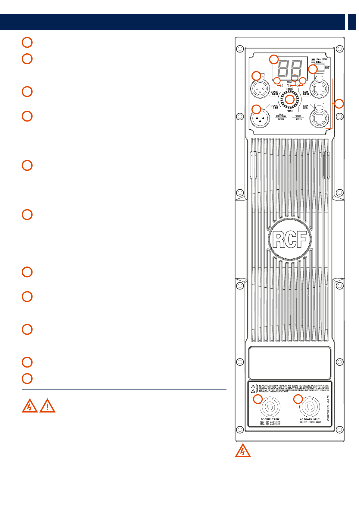
FEMALE XLR INPUTS (BAL/UNBAL) The system accepts XLR input connectors.
2
MALE XLR SIGNAL OUTPUT The output XLR connector provides a loop through for
speakers daisy chaining. The balanced connector is connected in parallel and can be used to
send the audio signal to other amplified speakers, recorders or supplementary amplifiers.
3
SYSTEM SET UP ENCODER Pushing the encoder allows the user to select a function
(gain reduction, delay, preset). Rotate the encoder to select a value or a preset.
4
POWER / GAIN REDUCTION LED
POWER LED: the LED lights green when the speaker is connected to the main power supply.
GAIN REDUCTION LED: pushing the encoder once, the LED will light; rotating the encoder the
gain can be set to the desired level. The gain reduction works in steps of 0,1 dB for the first 10
dB and than in 1 dB steps. The maximum reduction is 99 dB.
5
DELAY / SIGNAL LED
SIGNAL LED: the signal indicator lights green if there is and audio signal present on the main.
DELAY LED: pushing the encoder twice the delay indicator lights green. Rotating the encoder
the delay reached the desired value. The delay is expressed in meters and works in steps of 0,1
m for the first 10 m and than in 1 m steps. The maximum delay will be 20 meter.
6
PRESET / LIMITER LED
PRESET LED: Pushing the encoder three times the preset indicator lights green. Rotating the
encoder the desired preset will be loaded.
LIMITER LED: The amplifier has a built in limiter circuit to prevent clipping of the amplifiers
or overdriving the transducers. When the soft clipping circuit is active this LED blinks RED. It is
okay if it blinks occasionally. If the LED lights continuously, turn down the signal level.
7
SYSTEM SET UP DISPLAY It displays the system setting values. In case of RDNet active
connection a rotating segment will light up.
8
RDNET LOCAL SETUP/BYPASS. When released the local setup is loaded and RDNet
can only monitor the speaker. When switched the RDNet setup is loaded and bypass any
speaker local preset.
9
RDNET IN/OUT PLUG SECTION The RDNET IN/OUT PLUG SECTION features etherCON
connectors for the RCF RDNet protocol. This allows the user to completely control the speaker
using the RDNet software.
10
AC INPUT Powercon locking 3-pole AC mains.
11
AC OUTPUT Powercon locking 3-pole AC mains output.
WARNING! CAUTION! Loudspeaker connections should be only made
by qualified and experienced personnel having the technical know-how or enough
specific instructions (to ensure that connections are made correctly) in order to
prevent any electrical danger.
To prevent any risk of electric shock, do not connect loudspeakers when the
amplifier is switched on.
Before turning the system on, check all connections and make sure there are no
accidental short circuits.
The entire sound system shall be designed and installed in compliance with the
current local laws and regulations regarding electrical systems.
3. REAR PANEL FEATURES AND CONTROLS
1
2
3
4
7
6
8
9
11 10
WARNING: the Powercon connector is
used to disconnect the system from the power
supply network. It shall be easily accessible
after the installation and during the use of the
system.
PRESET LABEL
Loading ...
Loading ...
Loading ...