" Walker
P A r__ -r T CJ T A L. I=_ 0 I_ Y W 0 R K 0 U T
N r-1 I M
SEARS
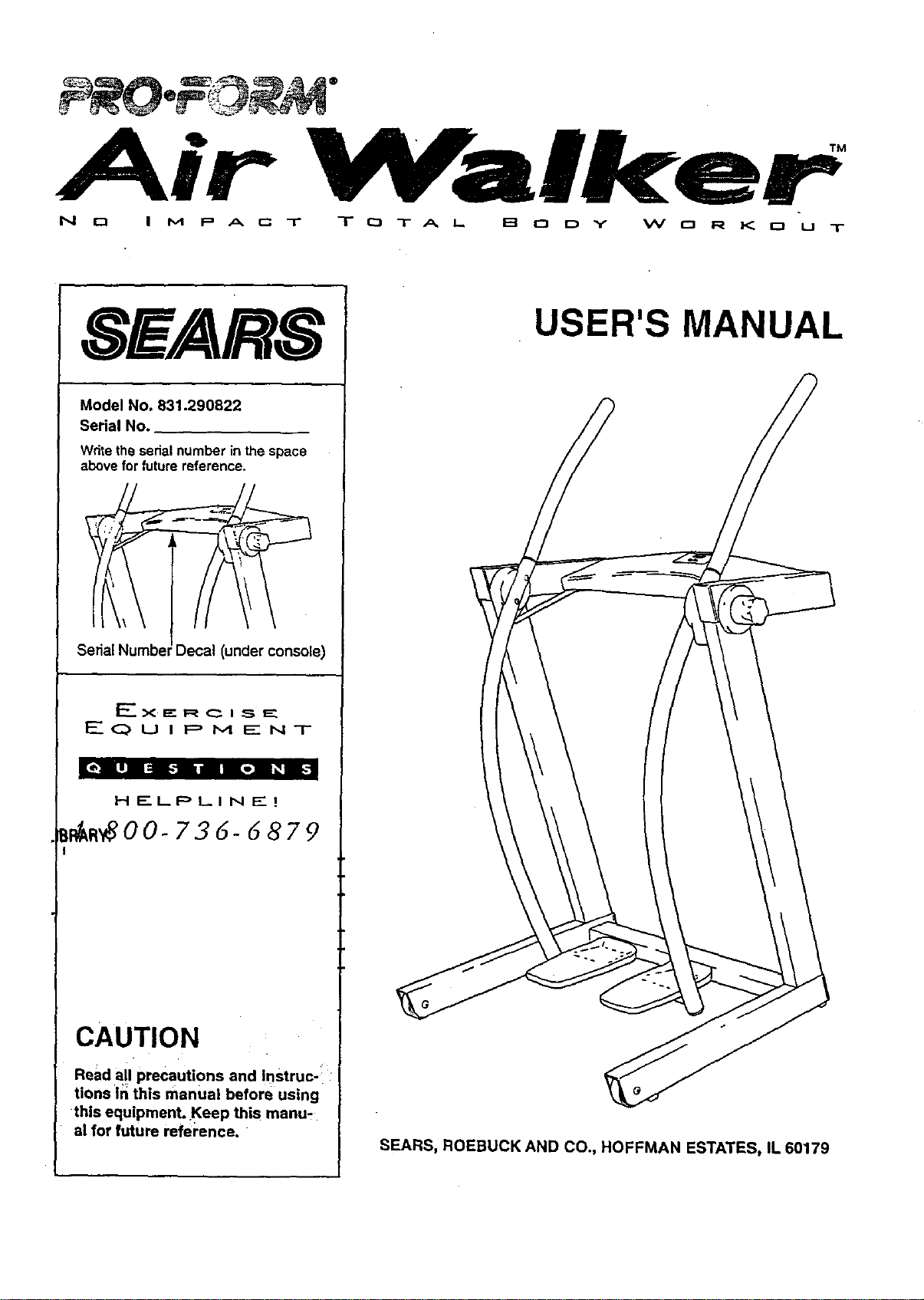
Model No. 831.290822
Serial No.
Wdte the serial number in the space
above for future reference.
Serial Numbel Decal (under console)
F-------.X._" R ___ I _, E_
,'____Q U i F=, M _" N T
[ol L|] I::i _,"]1i,a Bo] I_B
H E..I_PLI N EZ I
_m_O0- 736- d 879
CAUTION
Read all precautions and Instruc-:
tions in this manual before using
this equipment. Keep this manu-
al for future refel'ence.
USER'S MANUAL
SEARS, ROEBUCK AND CO., HOFFMAN ESTATES, IL 60179
TABLE OF CONTENTS
IMPORTANT PRECAUTIONS ............................................................. 2
BEFORE YOU BEGIN ................................................................... 3
ASSEMBLY ........................................................................... 4
HOW TO USE THE AIR WALKER .......................................................... 7
MAINTENANCE AND TROUBLE-SHOOTING ................................................. 8
CONDITIONING GUIDELINES ............................................................. 9
PART LIST ........................................................................... 10
EXPLODED DRAWING ................................................................. 11
ORDERING REPLACEMENT PARTS ................................................ Back Cover
FULL 90 DAY WARRANTY ....................................................... Back Cover
IMPORTANT PRECAUTIONS
WARNING: To reduce the risk of serious injury, read the following important precautions before
using the AIR WALKER.
1. It is 'i_e responsiS;lity of the owner toensure
that all users of the AIR WALKER are ade-
quately informed of all warnings and precau-
tions.
2. Read all Instructi0ns in this manual before
using the AIR WALKER.
3. Use the AIR WALKER only on a level surface.
Cover the floor beneath the AIR WALKER to
protect the floor or carpet.
4. Be sure that there are no obstacles in front of
or behind the AIR WALKER.
S. Inspect and tighten ell parts regularly.
Reolace any worn Darts immediately.
6, Keep small children and pets away from the
AIR WALKER at all times.
7; The AIR WALKER sh0uidnot be used by per-
sons weighing more than 250 pounds.
8. Keep hands and feet away from moving pads.
9. Do not wear loose clothing that could "
become caught on the AIR WALKER. Always
wear athletic shoes for foot protection when
exercising.
10. When you are getting onto and off the AIR
WALKER, always tighten the resistance
knobs, hold the handles firmly, and be sure
that your body weight is centered directly
over the pedals.
11. Use the AIR WALKER 0nly as described in
this manual.
12. If you feel faint, dizzy, or short of breath while
exercising, stop immediately and begin cool-
ing down.
13. The following precautions are printed on the
electronic monitor: Read User's Manual
before operating; To enter and exit, tighten
resistance knobs, grasp handles, and place
body directly over foot pedals; Stop if you
feel faint, dizzy, or short of breath; Keep chil-
dren away.
WARNING: Before beginning this or any exercise program, consult your physiCian. This is especially
Important for persons over the age of 35 or persons with pre-existing health problems. Reed all
instructions before using. SEARS assumes no responsibility for personal injury or ProPerty damage
sustained by or through the use of this produCt.
BEFORE YOU BEGIN
Thank you for selecting the innovative PROFQF_M_
AIR WALKER, The A)R "WALY.E_ b\e_6s &_,_&o,¢ed
engineering with contemporary stylin 9 to pTo'_de"_,_
with a n_-_m_ect, t_tal body workou_ in \'n_ _._._-
nience and privacy of your own home.
For your benefit, read this man_ eareful|y before
using the AIR WALKER. If you "nave a6_'=_ _,_s-
_,, _l_se. cat( our t_|Hres HELPLINE at 1-6t30-736-
6879, Monday through Saturday, 7 _.m, untO\7 p.rn.
Central lqme (,excluding holidays). To help us assist
yt)u, _4e_asenote the product model number an_ set)a)
n_mt3er 5efore c_.lling, The mode_ numbe{ "_s
_'&%2.9(3_2_#..The serial number can be found on a
decal attached to the AIR WALKER (see fhe"front
cover of th(s manua( for the location of the deca\).
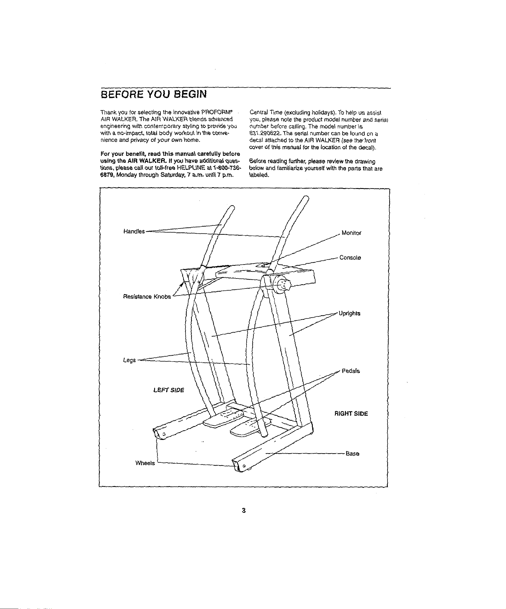
_efare reading further, please review the drawing
below and familiarize yourself with the pacts that are
\ahead.
Handles
Resistance
Legs
RIGHT SIDE
Wheels
3
ASSEMBLY
Before you begin assembly, carefully read the
following information and instructions:
• Place all parts of the AIR WALKER in a cleared
area and remove the packing matedals.
IMPORTANT: DO NOT REMOVE THE RUBBER
BANDS FROM THE HUB COVERS (see
assembly step 5). Do not dispose of any
packing matedals until assembly is completed.
• Use tl_edrawings below to identify the small
hardware used in assembly.
• Read through each assembly step before you
begin.
• - Make sure that all parts are oriented as shown in
the drawings. _ghten all parts as you assemble
them, unless instructed to do otherwise.
Assembly requires the following tools:
/
• the included allen wrench _
• your own phillips screwdriver
3/8" Curved Washer (27)-4
3/8" x 1/2" Screw (24)-8
#8 x 1/2" Screw (31)-8
1,
Before you begin, read the information at the
top of this page.
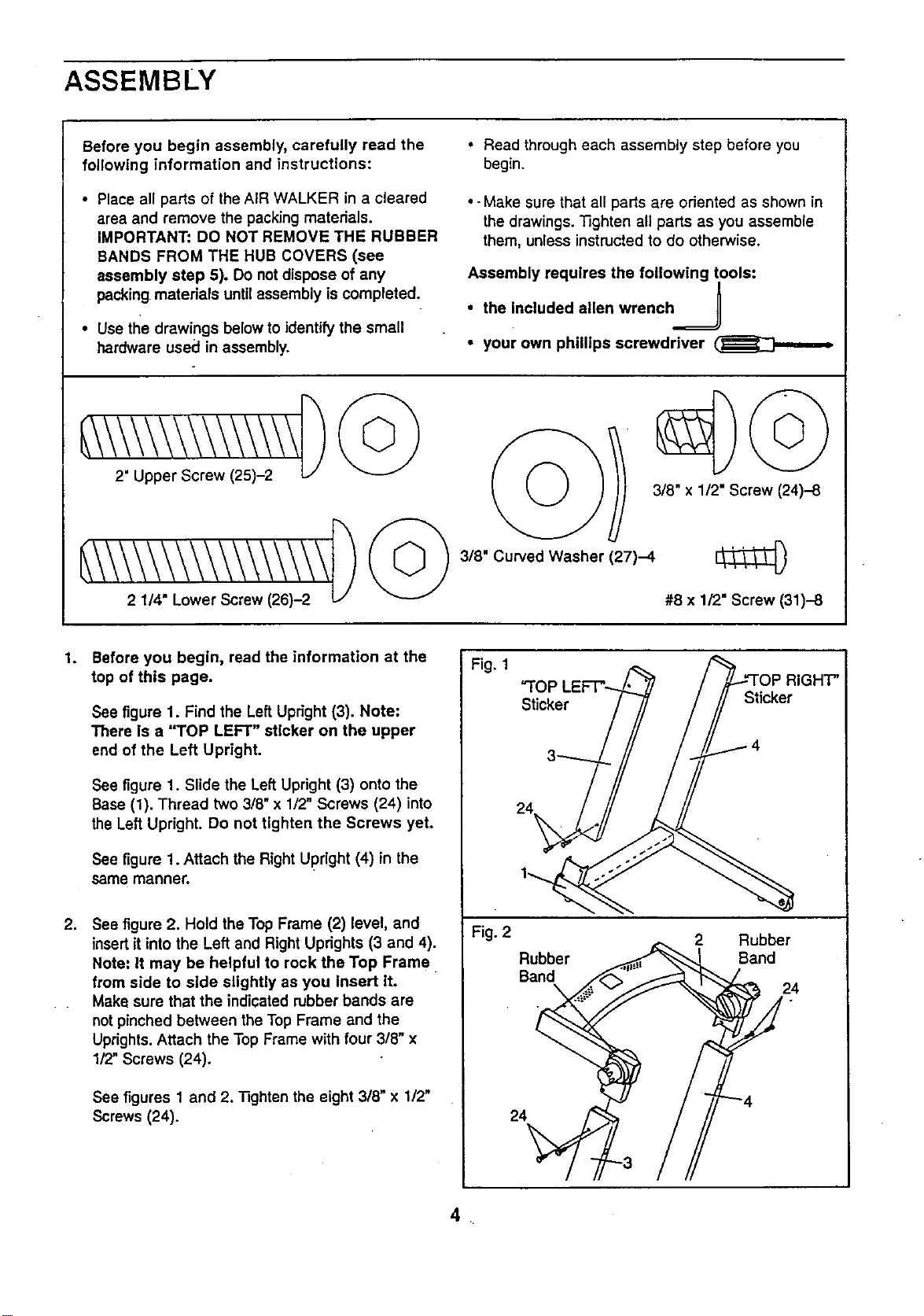
See figure 1. Find the Left Upright (3). Note:
There is a "TOP LEFT" sticker on the upper
end of the Left Upright.
See figure 1. Slide the Left Upright (3) onto the
Base (1). Thread two 3/8" x 1/2" Screws (24) into
the Left Upright. Do not tighten the Screws yet.
See figure 1. Attach the Right Upright (4) in the
same manner.
2. See figure 2. Hold the Top Frame (2) level, and
insert it into the Left and Right Uprights (3 and 4).
Note: It may be helpful to rock the Top Frame
from side to side slightly as you Insert it.
Make sure that the indicated rubber bands are
not pinched between the Top Frame and the
Uprights. Attach the Top Frame with four 3/8" x
1/2" Screws (24).
See figures 1 and 2. "nghten the eight 3/8" x 1/2"
Screws (24).
Fig. 1
Fig. 2
"TOP
Sticker
Sticker
4
24
Rubber
Band
2 Rubber
Sand
24
24
_H"P'
.
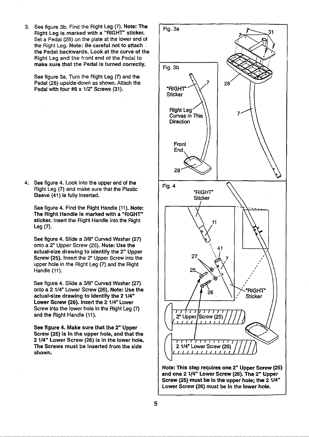
See figure 3b. Find the Right Leg (7). Note: The
Right Leg is marked with a "RIGHT" sticker,
Set a Pedal (28) on the plate at the lower end of
the Right Leg. Note: Be careful not to attach ,
the Pedal backwards. Look at the curve of the
Right Leg and the front end of the Pedal to
make sure that the Pedal is turned correctly.
See figure 3a. Turn the Right Leg (7) and the
Pedal (28) upside-down as shown. Attach the
Pedal with four #8 x 1/2" Screws (31).
4. See figure 4. Look into the upper end of the
Right Leg (7) and make sure that the Plastic
Sleeve (41) is fully inserted.
See figure 4. Find the Right Handle (11). Note:
The Right Handle is marked with a "RIGHT"
sticker. Insert the Right Handle intothe Right
Leg (7).
See figure 4. Slide a 3/8" Curved Washer (27)
onto a 2" Upper Screw (25). Note: Use the
actual-size drawing to identify the 2" Upper
Screw (25). Insert the 2" Upper Screw intothe
upper hole in the Right Leg (7) and the Right
Handle (11)o
See figure 4. Slide a 3/8" Curved Washer (27)
onto a 2 1/4" Lower Screw (26). Note: Use the
actual-size drawing to identify the 2 114"
Lower Screw (26). Insert the 2 1/4" Lower
Screw into the lower hole in the Right Leg (7)
and the Right Handle (11).
See figure 4. Make sure that the 2" Upper
Screw (25) is in the upper hole, and that the
2 1/4" Lower Screw (26) is in the lower hole.
The Screws must be inserted from the side
shown.
Fig. 3a
Fig. 3b
-RIGHT.-_ 7
Curves in This \
Dire_ion ))
Front / /
28_ _
7j
Fig. 4
"RIGHT'
Sticker
41
Note: This step requires one 2" Upper Screw (25)
and one 2 1/4" Lower Screw (26). The 2" Upper
Screw (25) must be in the upper hole; the 2 114"
Lower Screw (26) must be in the lower hole.
5
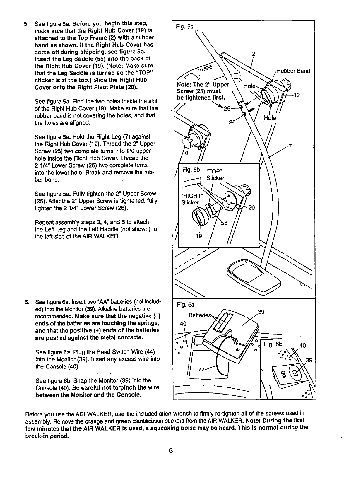
See figure 5a. Before you begin this step,
make sure that the Right Hub Cover (19) is
attached to the Top Frame (2) with a rubber
band as shown. If the Right Hub Cover has
come off during shipping, see figure 5b.
Insert the Leg Saddle (55) into the back of
the Right Hub Cover (19). (Note: Make sure
that the Leg Saddle is turned so the "TOP"
sticker is st the top.) Slide the Right Hub
Cover onto the Right Pivot Plate (20).
See figure 5a. Find the two holes inside the slot
of the Right Hub Cover (19). Make sure that the
rubber band is not covering the holes, and that
the holes are aligned.
See figure 5a. Hold the Right Leg (7) against
the Right Hub Cover (19). Thread the 2" Upper
Screw (25) two complete turns into the upper
hole inside the Right Hub Cover. Thread the
2 1/4" Lower Screw (26) two complete turns
into the lower hole. Break and remove the rub-
ber band.
See figure 5a. Fully tighten the 2" Upper Screw
(25). After the 2" Upper Screw is tightened, fully
tighten the 2 1/4" Lower Screw (26).
Repeat assembly steps 3, 4, and 5 to attach
the Left Leg and the Left Handle (not shown) to
the left side of the AIR WALKER.
6. See figure6a. Insert two "AA" batteries (not includ-
ed) into the Monitor (39). Alkaline batteries are
recommended. Make sure that the negative (-)
ends of the batteries are touching the springs,
and that the positive (+) ends of the batteries
are pushed against the metal contacts,
See figure 6a. Plug the Reed Switch Wire (44)
into the Monitor (39). Insert any excess wire into
the Console (40).
See figure 6b. Snap the Monitor (39) intothe
Console (40). Be careful not to]_inch the wire
between the Monitor and the Console.
Fig. 6a
40
2
Rubber Band
39
Before you use the AIR WALKER, use the included allen wrench to firmly re-tighten all of the screws used in
assembly. Remove the orange and green identificationstickers from the AIR WALKER. Note: During the first
few minutes that the AIR WALKER is used, a squeaking noise may be heard. This Is normal during the
break-in period.
6
HOW TO USE THE AIR WALKER
CAUTION: When you are getting onto and off
the AIR WALKER, always tighten the res!s-
tance knobs, hold the handles firmly, and be
sure that your body weight is centered direct-
ly over the pedals,
EXERCISING ON THE AIR WALKER
The proper form for exercising on the AIR WALKER
is similar to walking--move one leg forward as you
move the other leg back. Never attempt to move
both legs In the same dlractlon---you could be
injured, or the AIR WALKER could be damaged.
For a full body workout, hold the handles as you walk,
moving your arms and legs in motion with the handles
and pedals. To vary the effect on your muscles,
change your stance on the AIR WALKER. For exam-
ple, you can change the position of your hands on the
handles, or you can bend your legs slightly instead of
keeping them straight.
For a lower body workout, rest your hands on the
edge of the console for balance as you walk on the
pedals. Note: Do not lean on the console. It is not
designed to support your body weighL
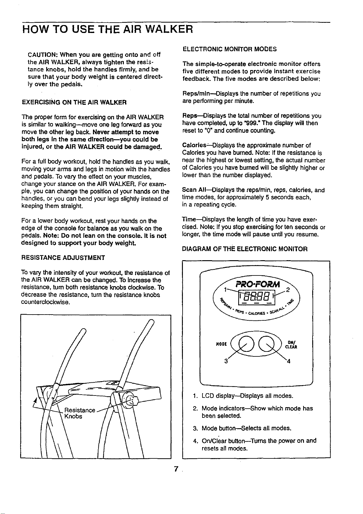
RESISTANCE ADJUSTMENT
To vary the intensity of your workout, the resistance of
the AIR WALKER can be changed. To increase the
resistance, turn both resistance knobs clockwise. To
decrease the resistance, turn the resistance knobs
counterclockwise.
Knobs
ELECTRONIC MONITOR MODES
The simple-to-operate electronic monitor offers
five different modes to provide instant exercise
feedback. The five modes are described below:
Reps/mtn--Displays the number of repetitions you
are performing per minute.
Reps--Oisplays the total number of repetitions you
have completed, up to "999." The display will then
reset to "0" and continue counting.
Calories_-Displays the approximate number of
Calories you have burned. Note: If the resistance is
near the highest or lowest setting, the actual number
of Calories you have burned will be slightly higher or
lower than the number displayed.
Scan All-Displays the reps/min, reps, calories, and
time modes, for approximately 5 seconds each,
in a repeating cycle.
Time--Displays the length of time you have exer-
cised. Note: If you stop exercising for ten seconds or
longer, the time mode will pause until you resume,
DIAGRAM OF THE ELECTRONIC MONITOR
f
1. LCD display--Displays all modes.
2. Mode indicators--Show which mode has
been selected.
3. Mode button--Selects all modes.
4. On/Clear button--Turns the power on and
resets all modes.
.
OPERATING THE ELECTRONIC MONITOR
1. To turn on the power, press the on/clear button or
simply begin exercising on the AIR WALKER. The
entire display will appear for two seconds. The
electronic monitor will then be ready ior operaucn.
2. Select one of the five modes:
Scan all mode---When the power is turned on, the
scan all mode will be selected automatically.The
scan all mode can also be selected by repeatedly
pressing the mode button. One mode indicator will
show that the scan all mode has been selected,
and a second mode indicator will show which
mode is currentlydisplayed.
Reps/min, reps, calories, or time mode--These
modes can be individuallyselected by repeatedly
pressing the mode button. The mode indicators
will show which mode has been selected. (Make
sure that the scan all mode is not selected.) The
motes will be selected in the following order:
reps/min, raps, calories, scan all, time.
.
The monitor has an auto-off feature to turn off
the power. If the pedals are not moved and the
monitor buttonsare not pressed for four minutes,
the powerwill turn off automatically in order to
conserve the batteries.
To reset the LCD display, press-the on/clear button.
MAINTENANCE AND TROUBLE-SHOOTING
MAINTENANCE
:Inspect and tighten all parts of the AIR WALKER reg-
ulady. Replace any worn parts immediately.
The AIR WALKER can be cleaned with a soft, damp
cloth. Keep liquids away from the electronic monitor.
.Keep the monitorout of direct sunlight or the display
may be damaged. Remove the batteries when stodng
the AIR WALKER.
ELECTRONIC MONITOR TROUBLE-SHOOTING
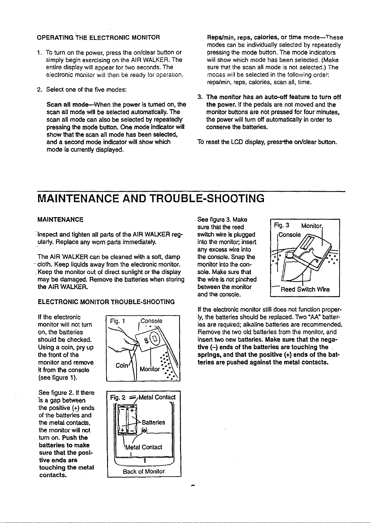
If the electronic
monitor will not turn Fig. 1
on, the batteries
should be checked.
Using a coin, pry up
the front of the
monitor and remove
it from the console
(see figure 1).
See figure 2. If there
is a gap between
the positive (+) ends
of the batteries and
the metal contacts,
the monitor will not
turn on. Push the
batteries to make
sure that the posi-
tive ends are
touching the metal
contacts.
Fig._Metal Contact
e ttedes
Metal Contact
t
U
Back of Monitor
See figure 3. Make
sure that the reed
switch wire is plugged
into the monitor;,insert
any excesswire into
the console.Snap the
monitorintothe con-
sole. Make sure that
the wire isnotpinched
between the monitor
and the console.
Fig. 3 Mon_,._
iConsole
Reed Switch Wire
If the electronicmonitor stilldoes not function proper-
ly, the batteries should be replaced. Two "AA" batter-
ies are required;alkaline batteries are recommended.
Remove the two old batteries from the monitor, and
insert two new batteries, Make sure that the nega-
tive (-) ends of the batteries are touching the
springs, and that the positive (+) ends of the bat-
teries are pushed against the metal contacts.
CONDITIONING GUIDELINES
The following guidelines will help you to plan your
exercise program. Remember that proper nutrition and
adequate rest are essential for successful results.
WARNING: Before beginning this or any exercise
program, consult your physician. This is espe-
cially important for individuals over the age of 35
or individuals with pre-existing health problems.
WHY EXERCISE?
Exemise has proven essential for good health and
general well-being. Regular participation in a well-
rounded exercise program helps to develop a stronger
and more efficient heart, improved respiratory function,
increased stamina and endurance, better weight man-
agement and body fat control, increased ability to deal
with stress, and greater self-esteem and confidence.
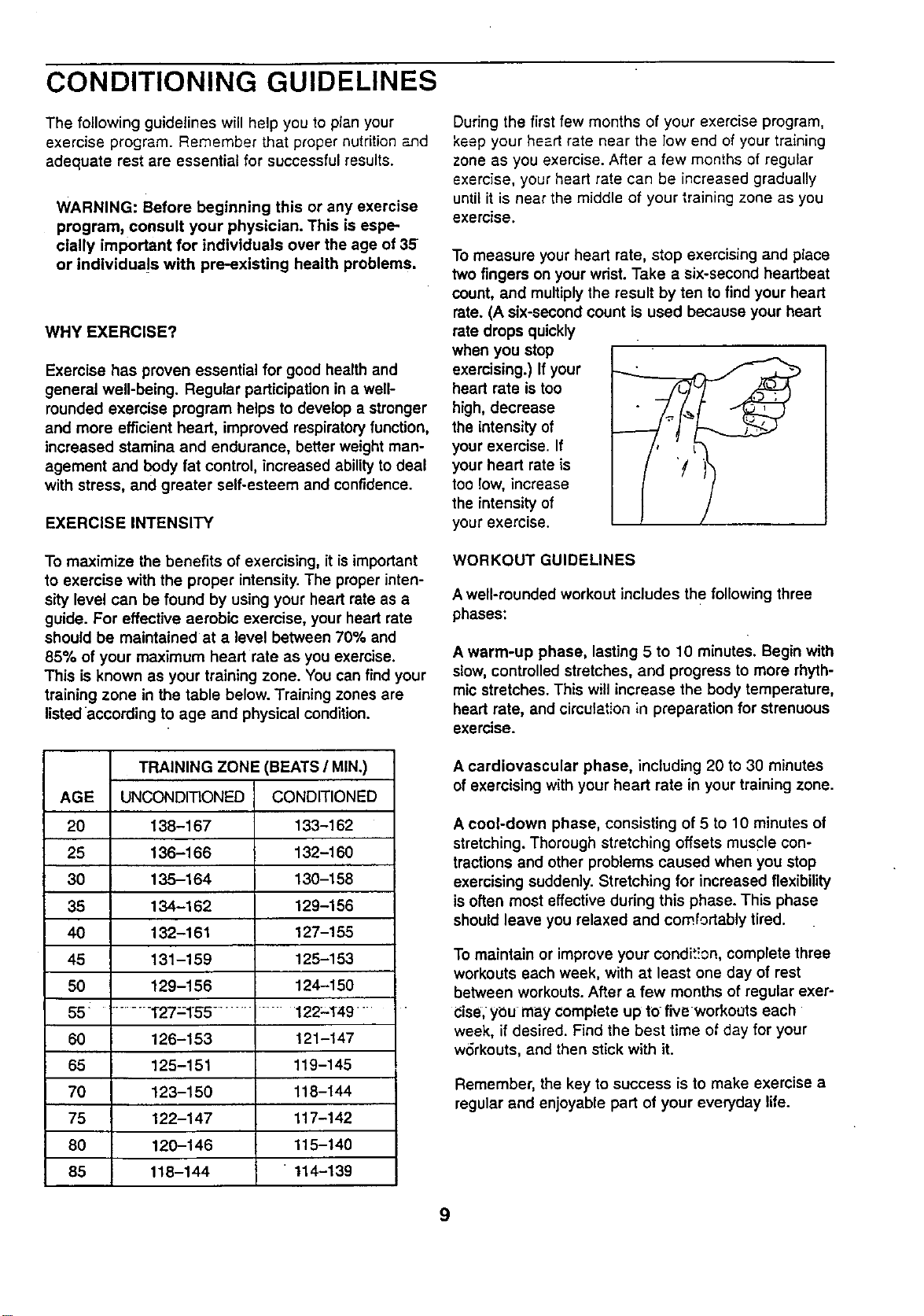
EXERCISE INTENSITY
To maximize the benefits of exercising, itis important
to exercise with the proper intensity.The proper inten-
sity level can be found by using your heart rate as a
guide. For effective aerobic exercise, your heart rate
should be maintained at a level between 70% and
85% of your maximum heart rate as you exercise.
This is known as your training zone. You can find your
training zone in the table below. Training zones are
listed according to age and physical condition.
TRAINING ZONE (BEATS/MIN.)
AGE UNCONDITIONED CONDITIONED
20 138-167 133-162
25 136-166 132-160
30 135-164 130-158
35 134-162 129-156
40 132-161 127-155
45 131-159 125-153
50 129-156 124-150
55 ......... T27=155 ......... 122-149 "
60 126-153 121-147
65 125-151 119-145
70 123-150 118-144
75 122-147 117-142
80 120-146 115-140
85 118-144 114-139
During the first few months of your exercise program,
keep your heart rate near the low end of your training
zone as you exercise. After a few months of regular
exercise, your heart rate can be increased gradually
until it is near the middle of your training zone as you
exercise.
To measure your heart rate, stop exercising and place
two fingers on your wdst. Take a six-second heartbeat
count, and multiply the result by ten to find your heart
rate. (A six-second count is used because your heart
rate drops quickly
when you stop
exercising.) If your
heart rate is too
high, decrease
the intensity of
your exercise. If
your heart rate is
too low, increase
the intensity of
your exercise.
WORKOUT GUIDELINES
A well-rounded workout includes the following three
phases:
A warm-up phase, lasting 5 to 10 minutes. Begin with
slow,controlled stretches, and progress to more rhyth-
mic stretches. This will increase the body temperature,
heart rate, and circulation in preparation for strenuous
exercise.
A cardiovascular phase, including 20 to 30 minutes
of exercising with your heart rate in your training zone.
A cool-down phase, consisting of 5 to 10 minutes of
stretching. Thorough stretching offsets muscle con-
tractions and other problems caused when you stop
exercising suddenly. Stretching for increased flexibility
is often most effective during this phase. This phase
should leave you relaxed and comfortably tired.
To maintain or improve your condit!cn, complete three
workouts each week, with at least one day of rest
between workouts. After a few months of regular exer-
Cise,ybu may complete up to five workouts each
week, if desired. Find the best time of day for your
wdrkouts, and then stick with it.
Remember, the key to success is to make exercise a
regular and enjoyable part of your everyday life.
9
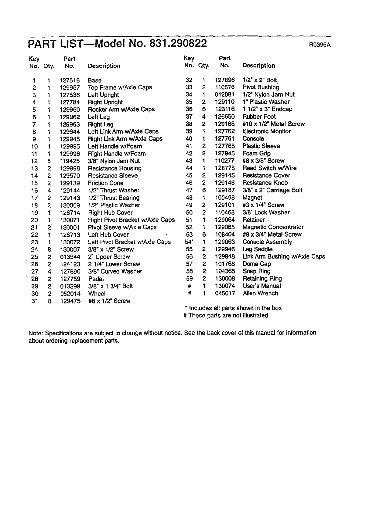
PART LIST--Model No. 831.290822 Ro396A
Key Part Key Part
No. Qty. No. Description No. Qty. No. Description
1 1 127518 Base 32 1 127896 112"x 2" Bolt
2 1 129957 Top Frame w/Axle Caps 33 2 110576 Pivot Bushing
3 1 127536 Left Upright 34 1 012081 lfZ' Nylon Jam Nut
4 1 127784 Right Upright 35 2 129110 1" Plastic Washer
5 1 129960 Rocker Arm w/Axle Caps 36 6 123116 1 1/2" x 3" Endcap
6 1 129962 Left Leg 37 4 126650 Rubber Foot
7 1 129963 Right Leg 38 2 129168 #10 x 1/'Z' Metal Screw
8 1 129944 Left LinkArm w/Axle Caps 39 1 127762 Electronic Monitor
9 1 129945 Right Link Arm w/Axle Caps 40 1 127761 Console
10 1 129995 Left Handle wlFoam 41 2 127765 Plastic Sleeve
11 1 129996 Right Handle wlFoam 42 2 127945 Foam Grip
12 8 119425 3/8" Nylon Jam Nut 43 1 110277 #8 x 3/8" Screw
13 2 129998 Resistance Housing 44 1 128775 Reed Switch w/Wire
14 2 129570 Resistance Sleeve 45 2 129145 Resistance Cover
15 2 129139 Friction Cone 46 2 129146 Resistance Knob
16 4 129144 1/2" Thrust Washer 47 6 129187 3/8" x 2" Carriage Bolt
17 2 129143 1/2"Thrust Bearing 48 1 100498 Magnet
18 2 130009 1/2" PlasticWasher 49 2 129101 #3 x 1/4" Screw
19 1 128714 Right Hub Cover 50 2 110468 3/8" Lock Washer
20 1 130071 Right Pivot Bracket w/Axle Caps 51 1 129064 Retainer
21 2 130001 Pivot Sleeve wlAxle Caps 52 1 129065 Magnetic Concentrator
22 1 128713 Left Hub Cover 53 6 108404 #8 x 3/4" Metal Screw
23 1 130072 Left Pivot Bracket w/Axle Caps 54* 1 129063 Console Assembly
24 8 130007 3/6" x 1/2" Screw 55 2 129946 Leg Saddle
25 2 013544 2" Upper Screw 56 2 129948 LinkArm Bushing wlAxle Caps
: 26 2 124123 2 1/4" Lower Screw 57 2 101768 Dome Cap
27 4 127890 3/8" Curved Washer 58 2 104365 Snap Ring
: 28 2 127759 Pedal 59 2 130008 Retaining Ring
29 2 013399 3/8" x 1 3/4" Bolt # 1 130074 User's Manual
30 2 052014 Wheel # 1 045017 Allen Wrench
31 8 129475 #8 x 1/2" Screw
* Includes all parts shown in the box
# These parts are not illustrated
Note: Specifications are subject to change without notice. See the back cover of this manual for information
about ordering replacement parts.
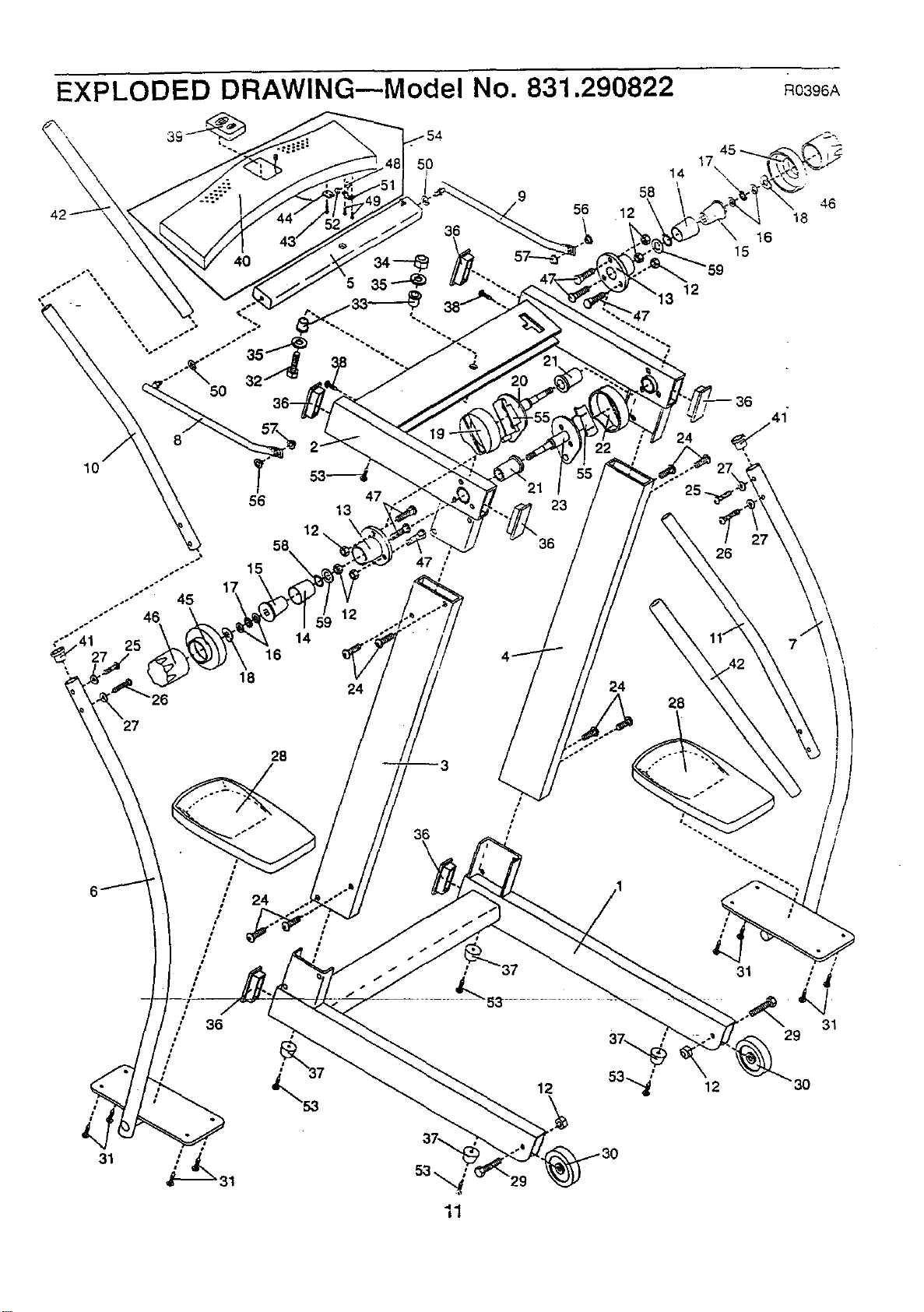
EXPLODED DRAWING--Model No. 831.290822 Ro396,_
5O
56 47
13
12
27
28
36
\
I 36
#
21
23
36
12
58
56 12
24
45
17
14 \
15
12
24
25_
26
28
16
41
\
31
12
46
18
31
29
3O
31
SEARS
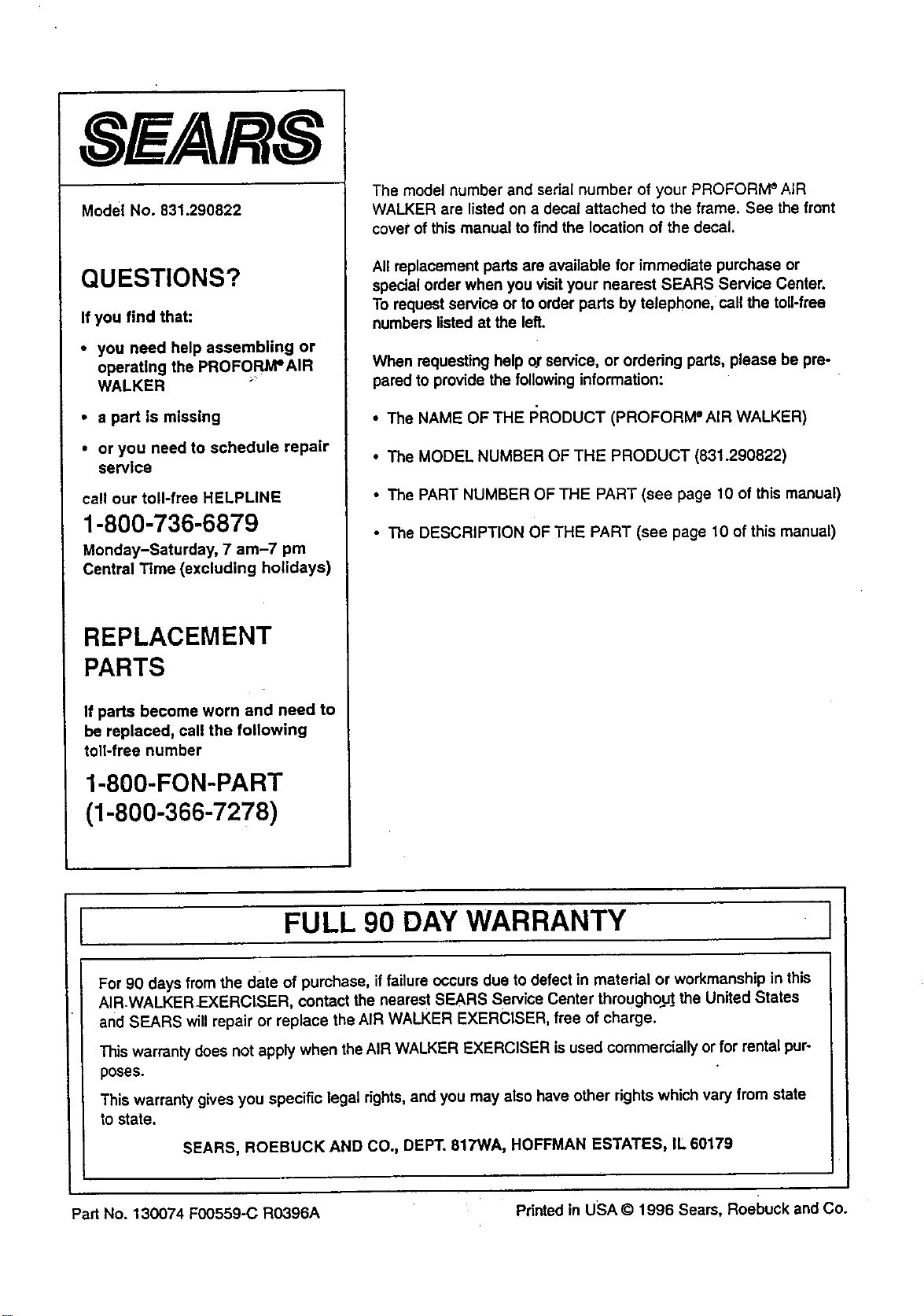
Model No. 831.290822
QUESTIONS?
If you find that:
• you need help assembling or
operating the PROFORJVPAIR
WALKER
• a part is missing
• or you need to schedule repair
service
call our toll-free HELPLINE
1-800-736-6879
Monday-Saturday, 7 am-7 pm
Central Time (excluding holidays)
REPLACEMENT
PARTS
If parts become worn and need to
be replaced, call the following
toll-free number
1-800-FON-PART
(1-800-366-7278)
The model number and serial number of your PROFORM ®AiR
WALKER are listed on a decal attached to the frame. See the front
covet of this manual to find the location of the decal.
All replacement parts are available for immediate purchase or
special order when you visityour nearest SEARS Service Center.
To request service or to order parts by telephone, call the toll-free
numbers listed at the left.
When requesting help or service, or ordering parts, please be pre-
pared to provide the following information:
• The NAME OF THE I:;RODUCT (PROFORM ° AIR WALKER)
• The MODEL NUMBER OF THE PRODUCT (831.290822)
• The PART NUMBER OF THE PART (see page 10 of this manual)
• The DESCRIPTiON OF THE PART (see page 10 of this manual)
I FULL 90 DAY WARRANTY I
For 90 days from the date of purchase, iffailure occurs due to defect in material or workmanship in this
AIR.WALKER-EXERCISER, contact the nearest SEARS Service Center throughout the United States
and SEARS will repair or replace the AIR WALKER EXERCISER, free of charge.
This warranty does not apply when theAIR WALKER EXERCISER is used commercially or for rental pur-
poses.
This warranty gives you specific legal rights,and you may also have other rights which vary from state
to state.
SEARS, ROEBUCK AND CO., DEPT. 817WA, HOFFMAN ESTATES, IL 60179
Part No. 130074 F00559-C RO396A Printed in USA © 1996 Seam, Roebuck and Co.