Owner's Manual
I CRRFTSMRH°I
Lawn Utility Vehicle
Model No.
247,270250
CAUTION: Before
using this product,
read this manual and
follow all safety rules
and operating
instructions.
• Safety
• Operation
• Maintenance
• Storage
• Espanbl
Sears, Roebuck And Co., Hoffman Estates, IL 60179 U.S.A.
Visit our website: www.sears.com/craftsman FORM NO. 769-00054
Printed in U.S.A. (2/2002)
Content Page
Warranty Information ................................ 2
Safe Operation Practices .......................... 3
Slope Gauge ............................................ 6
Setting Up ................................................. 7
Operation ................................................. 9
Maintenance ........................................... 14
Content Page
Service & Adjustment ............................. 18
Off-Season Storage ................................ 23
Trouble-Shooting .................................... 24
Parts List ................................................. 25
Espan61 .................................................. 42
Customer Support .................................. 64
LIMITED WARRANTY ON LAWN UTILITY VEHICLE: For two (2) years from the date of purchase, if this Craftsman Riding
Equipment is maintained, lubricated and tuned up according to the instructions in the owner's manual, Sears will repair or
replace free of charge any parts that are found to be defective in material or workmanship according to the guidelines of
coverage listed below.
Sears will also provide free labor for these applicable warranted parts for the two full years. During first 30 days of purchase,
there will be no charges to service the product at your home for issues covered by this warranty. (See exclusions below),
For your convenience, IN HOME warranty service will stillbe available after the first 30 days of purchase, but a trip charge will
apply. This charge will be waived if the product is dropped off at an authorized Sears location, For the nearest authorized Sears
location, please call 1-800-4-MY-HOM E®. This warranty applies only while this preduct is within the United States.
EXCLUSIONS
This Warranty does notcover:
• Expendable items which become worn dudng normal use, including but not limited to blades, spark plugs, air cleaners,
belts, and oil filters.
• Standard Maintenance Servicing, oil changes or tuoe-ups
• Tire replacement or repair caused by punctures from outside objects, such as nails, thorns, stumps, or glass.
• Repairs necessary because of operator abuse, including but not limited to, damage caused by towing objects beyond the
capability of the riding equipment, impacting objects that bend the frame or crankshaft, or over-speeding the engine.
Repairs necessary because of operator negligence, including but not limited to, electrical and mechanical damage caused
by improper storage, failure to usethe proper grade and amount of engine oil,failure to keep the deck clear of flammable
debris, or failure to maintain the equipment according to the ibstructionscontained in the owner's manual.
• Engine (fuel system) cleaning or repairs caused by fuel determined to be contaminated or oxidized (stale). In general, fuel
should be used within 30 days of its pumhase date.
• Normal deterioration and wear of the exterior finishes, or product label replacement.
• Riding equipment used for commercial or rental purposes.
LIMITED WARRANTY ON BATTERY
For ninety (90) days from date of purchase, ifany battery Included with this riding equipment proves defective in matedal or
workmanship and our testing determines the battery willnot hold charge, Sears will replace the battery at no charge. During the
first 30 days of purchase, there willbe no charges to replace the battery at your home, After the first30 days, for your
convenience, IN-HOME warranty service will stillbe available but a trip charge willapply. This charge will be waived ifthe
Craftsman product isdropped of at an authorized Sears location. For the nearest authodzed Sears location, please call 1-800-4-
MY-HOME®. This battery warranty applies only while this product iswithin the United States. This warranty gives you specific
legal rights, and you may also have other rights,which vary, from state to state.
Sears, Roebuck and Co.,Dept.817WA, Hoffman Estates, IL 60179
Horsepower: ............................... 6.75
Engine Oil ................................... 22 oz. or 0.65 liter
Fuel ............................................ Unleaded Regular
Spark Plug: ................................. PIN 692051
Engine: ........................................ 12607-0324-E1
Ignition Key ................................. PIN 725-0201
Model Number ........................... 247.270250
Sedal Number ...........................................................
Date of Purchase ......................................................
Record both serial number and date of purchase and keep
in a safe place for future reference.
WARNING: This symbol points out important safety instructionswhich, ifnot followed, could endanger
the personal safety and/or property of yourself and others. Read and followall instructionsin this manual
before attempting to operate this machine. Failure to complywith these instructionsmay result in personal
injury. When you see this symbol--heed itswarning.
WARNING: The Battery and Engine Exhaust contains chemicals known to the State of California
to cause cancer, birth defects or other reproductive harm. The battery and posts contain lead;
wash hands after handling.
WARNING: This machine was built to be operated according to the rules for safe operation in this
manual. As with any type of power equipment, carelessness or error on the part ofthe operator can resultin
sedous injury. This machine is capable of amputating hands and feet and throwing objects. Failure to
observe the followingsafety instructionscould result in serious injuryor death.
General Operation
1. Read, understand, and follow all instructionson the
machine and in the manual(s) before attempting to
assemble and operate. Keep this manual in a safe place
forfuture and regular reference and forordering
replacement parts.
2. Be familiar with all controls and their proper operation.
Know how to stop machine and disengage them quickly.
3. Never allow children under 14 years old to operate this
machine. Children 14 years old andover should read and
understand operation instructionsand safety rules in this
manual and should be trained and supervised by parent.
4. Never allow adults to operate this machine without
proper instruction.
5. To help avoid blade contact or athrown object injury,
keep bystanders, helpers, children and pets at least 75
feet from the machine while it isin operation. Stop
machine ifanyone enters the area.
6. Thoroughly inspect the area where the equipment isto
be used. Remove allstones, sticks, wire, bones, toys,
and other foreign objects which could be picked up and
thrown by the blade(s). Thrown objects can cause
serious personal injury.
7. Plan your mowing pattern to avoid discharge of material
toward roads, sidewalks, bystanders and the like. Also,
avoid discharging matedal against a wall or obstruction
which may cause discharged material to dcochet back
toward the operator.
8. Always wear safety glasses or safety goggles during
operation and while performing an adjustment or repairto
protect your eyes. Thrown objects which dcoshet can
cause serious injuryto the eyes.
9. Wear sturdy, rough-soled workshoes and close-fitting
slacks and shirts. Loose fitting clothes and jewelry can be
caught in movable parts. Never operate this machine in
bare feet or sandals.
10. Be aware of the mower and attachment discharge
direction and do not point itat anyone. Do net operate the
mower without the discharge cover or entire grass
catcher in its proper place.
11. Do not put hands or feet near rotatingparts or under the
cuffing deck. Contact with the blade(s) can amputate
hands and feet.
12. A missing or damaged discharge cover can cause blade
contactor thrown object injuries.
13. Stop the blade(s) when crossing gravel drives, walks, or
roads and while notcutting grass.
14. Watch for traffic when operating near or crossing
roadways. This machine is not Intended for use on any
publicroadway.
15. Do not operate the machine while under the influence of
alcohol or drugs.
16. Mow only indaylight or good artificiallight. Never carry
passengers.
17. Disengage blade(s) before shifting intoreverse. Back up
slowly.Always look down and behind before and while
backing to avoid a back-over accident.
18. Slow down before tuming. Operate the machine
smoothly. Avoid erratic operation and excessive speed.
19. Disengage blade(s), sat parking brake, stop engine and
wait untilthe blade(s) come to a complete stop before
removing grass catcher, emptying grass, unclogging
chute, removing any grass or debds, or making any
adjustments.
20. Never leave a running machine unattended. Always turn
off blade(s), place transmission in neutral, set parking
brake, stop engine and remove key before dismounting.
21. Use extra care when loading or unloading the machine
intoa traileror truck. This unit should not beddven up or
down ramp(s), because the unitcould tip over, causing
serious personal injury.The unitmust be pushed
manually on ramp(s) to load or unload pmpedy.
22. Muffierandenginebecomehotandcancauseabum.Do
nottouch.
23. Check overheed clearances carefully before ddving
under low tree branches, wires, door openings etc.,
where the operator may be struck or pulled fromthe unit,
whichcould result in serious injury.
24. Disengage all sttachment clutches, depress the brake
pedal completely and shift into neutral before attempting
tostart engine.
25. Your machine isdesigned tocut normal residential grass
ofa height no more than 10". Do not attempt to mow
through unusually tall, dry grass (e.g., pasture) or piles of
dryleaves. Dry grass or leaves may contact the engine
exhaust and/or build upon the mower deck presenting a
potential fire hazard.
3
26. Use only accesaories and attachments approved for this
machine by the machine manufacturer. Read,
understand and follow all instructions provided with the
accessory or attachment.
27. Data indicates thatoperators, age 60 years and above,
are involved in a large percentage of tractor-relsted
injuries. These operators should evaluate their ability to
operate the tractor safely enough to protect themselves
and others from serious injury.
28. Ifsituations occur which are notcovered inthis manual,
use care and good judgment. Contact Sears service
center for assistance.
Slope Operation
Slopes are a major factor related to loss ofcontrol and tip-
over accidents which can result in severe injuryor death. All
slopes require extra caution. If you cannot back up the slope
or ifyou feel uneasy, do not mow it.
For safety, use the slope gauge included as part of this
manual to measure slopes before operating this uniton s
sloped or hilly area. Ifthe slope isgreater than 15 degrees as
shown on the slope gauge, do not operate this unitthere.
Do:
1. Mow up and down slopes, not across. Exercise extreme
caution when changing direction on slopes.
2. Watch for holes, ruts, bumps, rocks, or other hidden
objects. Uneven terrain could overturnthe machine. Tall
grass can hide obstacles.
3. Use slow speed. Choose a low enough speed setting so
that you will not have to stop or shiftwhile on the slope,
Tires may lose traction on slopes even though the brakes
are functioning properly. Always keep machine in gear
when going down slopes totake advantage ofengine
braking action.
4. Follow the manufacturer's recommendations for wheel
weights or counterweights to improve stability of the
machine. Usa extra care with grass catchers or other
attachments. These can change stability of the machine.
5. Keep all movement on the slopes slow and gradual. Do
notmake sudden changes in speed or direction. Rapid
engagement or braking could cause the front of the
machine to liftand rapidly flipover backwards which
could cause serious injury.
6. Avoid starting or stopping on a slope. If tires lose traction,
disengage the blade(s) and proceed slowly straight down
the slope.
Do Not"
1. Do not turn on slopes unless necessary;,then, turn slowly
and gradually downhill, if possible.
2. Do not mow near drop-off sites,ditches or embankments.
The mower could suddenly turn over ifa wheel isover the
edge of a cliff, ditch, or ifan edge caves in.
3. Do not try tostabilize the machine by putting your foot on
the ground.
4. Do not use a grass catcher on steep slopes.
5. Do not mow on wet grass. Reduced traction could cause
sliding.
6. Do not shift to neutral and coast downhill. Over-speeding
may cause the operator to lose controlof the machine
resulting in serious injuryor death.
7. Do not tow heavy pull behind attachments (e.g. loaded
dump cart, lawn roller, etc.) on slopes greater than 5
degrees.Whengoingdownhill,theextraweighttendsto
pushthetractorandmaycauseyoutoloosecontrol.(e.g.
tractor mayspeed up,brakingand steedngabilityare
reduced,attachmentmayjsck-kniteandcausetractorto
overfum).
Children
1,
Tragic accidents can occur it the operator isnot alert to
the presence of children. Children are often attracted to
the machine and the mowing activity.They do not
understand the dangers. Never assume that children will
remain where you lastsaw them.
a. Keep children out of the mowing area and in
watchful care ofa responsible adult other than the
operator.
b. Be alert and turn machine off if a childenters the
area.
c. Before and while backing, look behind and down
for small children.
d. Never carry children, even with the blade(s) shut
off. They may fall off and be seriously injured or
interfere with safe machine operation.
e. Usa extreme care when approaching blind
corners, doorways, shrubs, trees or other objects
that may block yourvision of a child who may run
intothe machine.
f. Disengage the cutting blede(s) before shifting in
reverse. The =No-Cut-in Reverse" feature
emphasizes notto cut in reverse and to avoid
back-over accidents; do not defeat it.
Keep children away from hot or running engines.
They can suffer burns from a hotmuffler.
Remove key when machine isunattended to
prevent unauthorized operation.
Never allow children under 14 years old to operate the
machine. Children 14 years oldand over should read and
understand the operation instructionsand safety rules in
this manual and should be trained and supervised by a
g.
h.
2.
parent.
Service
Safe Handling Of Gasoline
1. To avoid personal injury or propertydamage usa extreme
care in handling gasoline. Gasoline isextremely
flammable and the vapors are explosive. Serious
personal injurycan occur when gasoline is spilled on
yourself or your clothes which can ignite.Wash your skin
and change clothes immediately.
a. Usa only an approved gasoline container.
b. Never fill containers inside a vehicle or on atruck
or trailer bed with a plastic liner. Always place
containers on the ground away from your vehicle
before filling.
c. When practical, remove gas-powered equipment
from the truck or trailor and refuel it on the ground.
If this isnot possible, then refuel such equipment
on a trailer with a portable container, rather than
trom a gasoline dispenser nozzle.
d. Keep the nozzle in contact with the rim ofthe fuel
tank or container opening at all times until fueling
iscomplete. Do not use a nozzle lock-open
device.
4
e. Extinguishall cigarettes, cigars, pipes and other
sources of ignition.
f. Never fuel machine indoors.
g. Never remove gas cap or add fuel while the
engine is hot or running. Allow engine to coolat
least two minutes before refueling.
h. Never over fill fuel tank. Fill tank to no more than
½ inch below bottom offiller neck to allow space
for fuel expansion.
i. Replace gasoline cap and tighten securely.
j. If gasoline isspilled, wipe itoff the engine and
equipment. Move unit to another area. Wait 5
minutes before starting the engine.
k. To reduce fire hazards, keep machine free of
grass, leaves, or other debris build-up. Clean up
oil orfuel spillage and remove any fuel soaked
debris.
L Never store the machine orfuel container inside
where there isan open flame, spark or pilot light
as on a water heater, space heater, fumace,
clothes dryer or other gas appliances.
m. Allow a machine to cool at least 5 minutes before
storing.
General Service
1. Never run an engine indoors or in apoorly ventilated
area. Engine exhaust contains carbon monoxide, an
odorless, and deadly gas.
2. Before cleaning, repeidng, or inspecting, make certain
the blade(s) and all moving parts have stopped.
Disconnect the spark plug wire and ground against the
engine to prevent unintended starting.
3. Periodically check to make sure the blades come to
complete stop within approximately (5) five seconds after
operating the blade disengagement control. Ifthe blades
do not stop within the this time frame, your unit shouldbe
serviced professionally by an authorized dealer.
4. Check brake operation frequently as it issubjected to
wear dudng normal operation. Adjust and service as
required.
5. Check the blade(s) and engine mounting bolts at
frequent intervals for proper tightness. Also, visually
inspect blade(s) for damage (e.g., excessive wear, bent,
cracked).
DANGER
Replace the blade(s) with the original equipment
manufacturer's (O.E.M.) blade(s) only, listed in this
manual. "Use of parts which do not meet the original
equipment specifications may lead to improper
performance and compromise safety!"
6. Mower blades are sharp. Wrap the blade or wear gloves,
and use extra caution when servicing them.
7. Keep all nuts, bolts, and screws tight to besure the
equipment isin safe working condition.
8. Never tamper with the safety interlock system or other
safety devices. Check theirproper operation regutarly.
9. After striking aforeign object, stopthe engine, disconnect
the spark plug wire(s) and ground against the engine.
Thoroughly inspect the machine for any damage. Repair
the damage before starting and operating.
10. Never attempt tomake adjustments or repairs to the
machine while the engine isrunning.
11. Grass catcher components and the discharge cover are
subject to wear and damage which could expose moving
parts or allow objects to be thrown. For safety protection,
frequently check components and replace immediately
with original equipment manufacturer's (O.E.M.) parts
only, listed in this manual. "Use ofparts which do not
meet the original equipment specifications may lead to
improper performance and compromise safety!"
12. Do not change the engine governor settings or over-
speed the engine. The governor controls the maximum
safe operating speed ofthe engine.
13. Maintain or replace safety and instruction labels, es
necessary.
14. Observe proper disposal laws and regulations for gas,
oil, etc. to protect the environment,
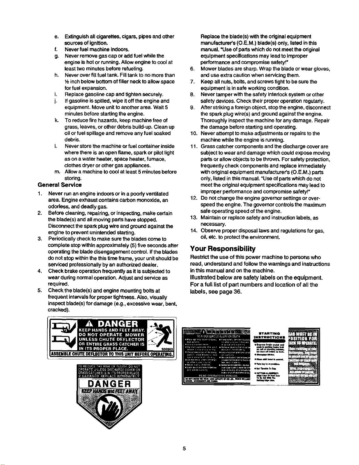
Your Responsibility
Restrict the use of this power machine to persons who
read, understand and follow the warnings and instructions
in this manual and on the machine.
Illustrated below are safety labels on the equipment.
For a full list of part numbers and location of all the
labels, see page 36.
I_FARTINQ
114s'lrN U C'lrlid HS
m
e|41_t_ ttu4 I_l_ iod
one, a _,w h m
• _,r_N _n
5
la=
0
0
"o
.q
0
D.
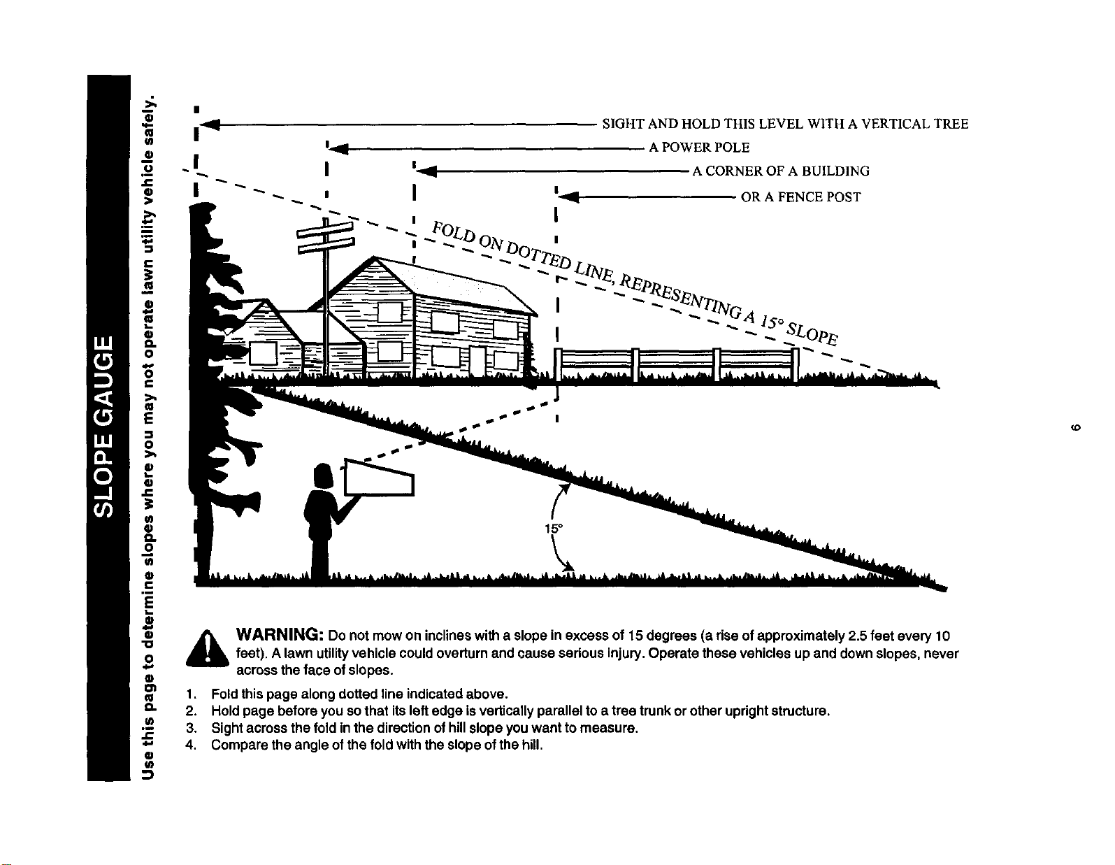
WARNING: Do not mow on inclineswith a slope in excess of 15 degrees (a rise ofapproximately 2.5 feet every 10feet). A lawn utilityvehicle could overturn and cause serious injury. Operate these vehicles up and down slopes, never
across the face ofslopes.
1. Fold this page along dotted line indicated above.
2. Hold page before you sothat its leftedge is vertically parallel toa tree trunk or other updghtstructure.
3, Sight across the fold in the direction of hillslope you want to measure.
4, Compare the angle of the fold with the slope of the hill.
(D
Unpacking Unit
1. Remove all screws and staples from the crete.
2. Holding sides of the crete firmly, lifttop ofthe crate
up and set itaside. Avoid tire punctures.
3. Remove and discard plastic bag covering the unit.
4. Liftthe rear ofthe vehicle offthe crate. Repeat for
the front. This may require two people.
5. Remove plastic bag and itscontents (owner's
manual, ignitionkeys etc.) that are packed on the
steering shaft.
6. Refer to Figure 7 in Owner's Manual for location of
the parking brake. Check to make sure that the
parking brake isdisengaged so thatthe vehicle can
be rolled forward.
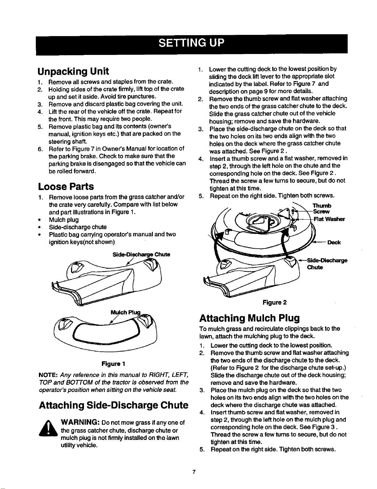
Loose Parts
1. Remove loose parts from the grass catcher and/or
the crate very carefully. Compare with list below
and part illustrationsin Figure 1.
• Mulch plug
• Side-discharge chute
• Plastic bag carrying operator's manual and two
ignitionkeys(not shown)
Side-Discharge Chute
1. Lower the cutting deck to the lowest positionby
sliding the deck liftlever to the appropriate slot
indicated bythe label. Refer to Figure 7 and
description on page 9 for more details.
2. Remove the thumb screw and flat washer attaching
the two ends ofthe grass catcher chute tothe deck.
Slide the grass catcher chute out of the vehicle
housing; remove and save the hardware.
3. Place the side-discharge chute on the deck sothat
the two holes on itstwo ends align with the two
holes on the deck where the grass catcher chute
was attached. See Figure 2.
4. Insert a thumb screw and a flat washer, removed in
step 2, through the left hole on the chute and the
corresponding hole on the deck. See Figure 2.
Thread the screw a few turns to secure, but do not
tighten at this time.
5. Repeat on the dght side. Tighten both screws.
Thumb
-Rat Washer
Figure 1
NOTE: Any reference in this manual to RIGHT, LEFT,
TOP and BOTTOM of the tractor is observed from the
operator's position when sitting on the vehicle seat.
Attaching Side-Discharge Chute
WARNING: Do not mow grass ifany one of
the grass catcher chute, discharge chute or
mulch plug is notfirmly installed on the lawn
utilityvehicle.
Figure 2
Attaching Mulch Plug
To mulch grass and recirculate clippingsback to the
lawn, attach the mulching plug tothe deck.
1. Lower the cutting deck tothe lowest position.
2. Remove the thumb screw and flatwasher attaching
the two ends of the discharge chute to the deck.
(Refer to Figure 2 for the discharge chute set-up.)
Slide the discharge chute out of the deck housing;
remove and save the hardware.
3. Place the mulch plugon the deck so that the two
holes on itstwo ends align with the two holes on the
deck where the discharge chute was attached.
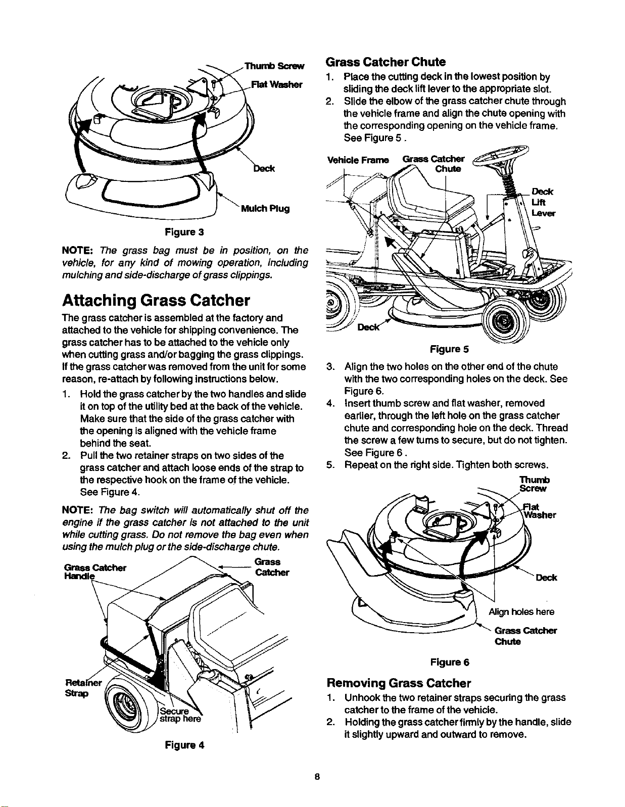
4. Insert thumb screw and fiatwasher, removed in
step 2, through the left hole on the mulch plug and
corresponding hole on the deck. See Figure 3.
Thread the screw a few turnsto secure, but do not
tighten at this time.
5. Repeat on the right side. Tighten both screws.
Flat Washer
Deck
_ Mulch Plug
Figure 3
NOTE: The grass bag must be in position, on the
vehicle, for any kind of mowing operation, including
mulching and side-discharge ofgrass clippings.
Attaching Grass Catcher
The grass catcher is assembled at the factory and
attached to the vehicle for shipping convenience. The
grass catcher has to be attached to the vehicle only
when cuffing grass and/or bagging the grass clippings.
Ifthe grass catcher was removed from the unitfor some
reason, re-attach byfollowing instructionsbelow.
1. Hold the grass catcher bythe two handles and slide
it on top ofthe utilitybed at the back ofthe vehicle.
Make sure that the side of the grass catcher with
the opening is aligned with the vehicle frame
behind the seat.
2. Pull the two retainer straps on two sides ofthe
grass catcher and attach loose ends ofthe strap to
the respective hook on the frame ofthe vehicle.
See Figure 4.
NOTE: The bag switch will automatically shut off the
engine if the grass catcher is not attached to the unit
while cutting grass. Do not remove the bag even when
using the mulchplug or the side-discharge chute.
Grass
Grass Catcher
Handle Catcher
Grass Catcher Chute
1,
2.
Place the cuffing deck in the lowest posiUonby
sliding the deck lift lever to the appropriate slot.
Slide the elbow ofthe grass catcher chute through
the vehicle frame and align the chute opening with
the corresponding opening on the vehicle frame.
See Figure 5.
Vehicle Frame Grass Catcher
Chute
Deck
-Lift
Lever
Figure 5
3. Align the two holes on the other end ofthe chute
with the two corresponding holes on the deck. See
Figure 6.
4. Insert thumb screw and fiat washer, removed
earlier, through the left hole on the grass catcher
chute and corresponding hole on the deck. Thread
the screw a few turnsto secure, but do not tighten.
See Figure 6.
5. Repeat on the rightside. Tighten both screws.
Thumb
Screw
Deck
strap
Figure 4
Alignholeshere
Grass Catcher
Chute
Figure 6
Removing Grass Catcher
1. Unhook the two retainer straps securing the grass
catcher to the frame ofthe vehicle.
2. Holding the grass catcher firmlyby the handle, slide
it slightlyupward and outward to remove.
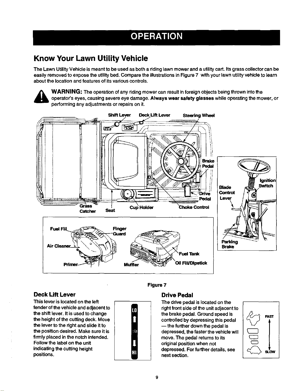
Know Your Lawn Utility Vehicle
The Lawn Utility Vehicle is meant tobe used as both a ridinglawn mower and a utilitycart. Itsgrass collectorcan be
easily removed to expose the utility bed. Compare the illustrationsin Figure 7 withyour lawn utilityvehicle to learn
about the location and features of itsvadous controls.
,_ WARNING: The operation of any riding mower can resultinforeign objects being thrown intotheoperator's eyes, causing severe eye damage. Always wear safety glasses while operating the mower, or
3erforming any adjustments or repairs on it.
Ignition
Switch
Rnger
_Gual't:l :uelTank
Muffler RII/Dlpstick
Parldng
Brake
Deck Lift Lever
This lever islocated on the left
fender ofthe vehicle and adjacent to
the shift lever. It is used to change
the height ofthe cutting deck. Move
the lever to the right and slideitto
the position desired. Make sure it is
firmlyplaced in the notch intended.
Follow the label on the unit
indicating the cuffing height
positions.
Figure 7
Drive Pedal
The drive pedal is located on the
rightfrontside ofthe unitadjacent to
the brake pedal. Ground speed is
controlledby depressing this pedal
-- the further down the pedal is
depressed, the faster the vehicle will
move. The pedal returns to its
originalposition when not
depressed. Forfurther details, see
next section.
SLOW
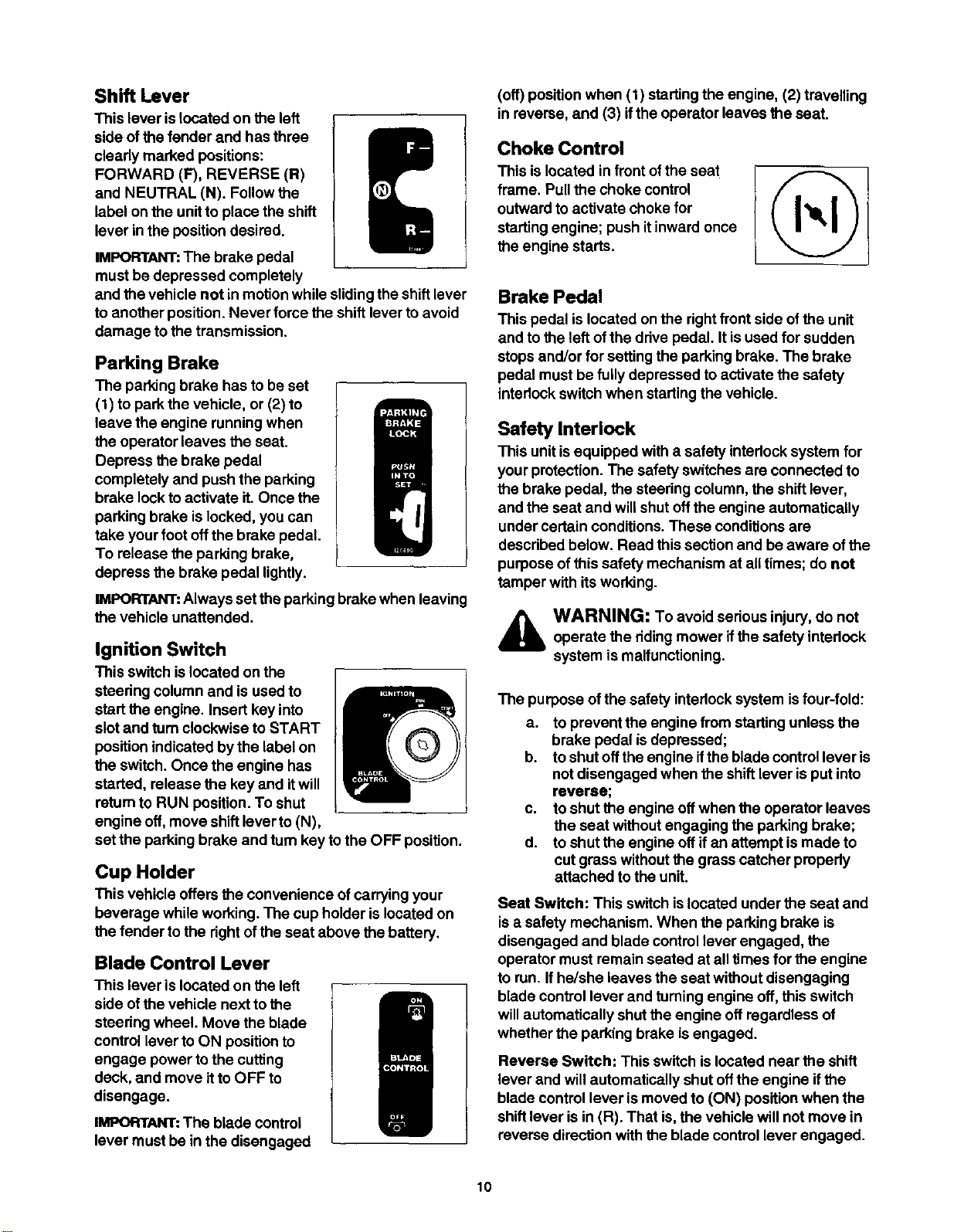
ShiR Lever
This lever islocated on the left
side of the fender and has three
clearly marked positions:
FORWARD (F), REVERSE (R)
and NEUTRAL (N). Followthe
label on the unitto place the shift
lever in the position desired.
IMPORTANT:The brake pedal
must be depressed completely
and the vehicle not inmotion while slidingthe shift lever
to another position. Never force the shift lever to avoid
damage to the transmission.
Parking Brake
The parking brake has to be set
(1) to park the vehicle, or (2) to
leave the engine running when
the operator leaves the seat.
Depress the brake pedal
completely and push the parking
brake lockto activate it. Once the
parking brake islocked, you can
take your foot offthe brake pedal.
To release the parking brake,
depress the brake pedal lightly.
IMPORTANT:Always set the parking brake when leaving
the vehicle unattended.
Ignition Switch
This switch islocated on the
steering column and is used to
start the engine. Insert key into
slot and turnclockwise to START
position indicated by the label on
the switch. Once the engine has
started, release the key and itwill
return to RUN position. To shut
engine off, move shiftlever to (N),
set the parking brake and turn key tothe OFF position.
Cup Holder
This vehicle offers the convenience ofcarrying your
beverage while working. The cup holder is located on
the fender tothe rightof the seat above the battery,
Blade Control Lever
This lever is located on the left
side ofthe vehicle next to the
steedng wheel. Move the blade
control lever to ON position to
engage power to the cuffing
deck, and move itto OFF to
disengage.
IMPORTANT..The blade control
lever must be in the disengaged
(off) position when (1) startingthe engine, (2) travelling
in reverse, and (3) ifthe operator leaves the seat.
Choke Control
This islocated in frontofthe seat
frame. Pull the choke control
outward to activate choke for
starting engine; push itinward once
the engine starts.
Brake Pedal
This pedal islocated on the rightfront side of the unit
and to the left of the drive pedal. It isused for sudden
stops and/or for setting the parkingbrake. The brake
pedal must be fullydepressed to activate the safety
interlockswitch when startingthe vehicle.
Safety Interlock
This unitis equipped witha safety intedock system for
your protection. The safety switches are connected to
the brake pedal, the steering column, the shift lever,
and the seat and will shut offthe engine automatically
under certain conditions. These conditions are
descdbed below. Read this section and be aware of the
purpose of this safety mechanism at all times; do not
tamper with its working.
_lb WARNING: To avoid serious injury, do notoperate the ridingmower if the safety intedock
system is malfunctioning.
The purpose ofthe safety intedock system isfour-fold:
a. to prevent the engine from starting unless the
brake pedal isdepressed;
b. to shut offthe engine ifthe blade control lever is
not disengaged when the shiftlever is put into
reverse;
c. to shut the engine offwhen the operator leaves
the seat without engaging the parking brake;
d. to shut the engine off ifan attempt is made to
cut grass without the grass catcher propedy
attached to the unit.
Seat Switch: This switch islocated under the seat and
isa safety mechanism. When the parking brake is
disengaged and blade controllever engaged, the
operator must remain seated at all times for the engine
to run. If he/she leaves the seat without disengaging
blade control lever and turning engine off, this switch
willautomatically shut the engine oft regardless of
whether the parking brake is engaged.
Reverse Switch: This switch is located near the shift
lever and willautomatically shut offthe engine if the
blade control lever is moved to (ON) position when the
shift lever is in (R). That is,the vehicle will not move in
reverse direction withthe blade controllever engaged.
10
Brake Switch: This switch islocated under the brake
pedal assembly. The engine will not start without first
depressing the brake pedal. This switch will also shut
offthe engine if the operator attempts to get offthe unit
without setting the parking brake,
Blade Control Switch: This switch is located in the
steering column. Ifthe operator attempts to start the
engine, get offthe seat or remove grass bag with the
blade controllever stillengaged, it will shut engine off.
Grass Bag Switch: This switch is located in the
bulkhead behind the engine. Ifthe operator attempts to
cut grass when the grass catcher isnot properly
attached to the vehicle, itwill shut engine off.
Before Starting
Filling Up Oil
Check oillevel inthe engine oilsump before starting the
engine. (Oil sump capacity: 22 ozJ0.65 liter)
1. Place the vehicle on level ground and flipthe seat
up to access the engine.
2. With a dry rag, clean the area around the oilfillon
the engine.
3. Remove dipstick and wipe it clean with cloth.
4. Replace and tighten the dipstick. Remove the
dipstick again and check the oillevel mark on it.
The oillevel should beat FULL line on the dipstick.
Ifthe level isshort ofthat, add oil tothe oilfillslowly.
Recheck the oil level on the dipstick. If needed, add
more oil. Do not overfill.
NOTE: The lawn utility vehicle is shipped with oil in the
engine crankcase.
5. Place the dipstick inposition and tighten to secure.
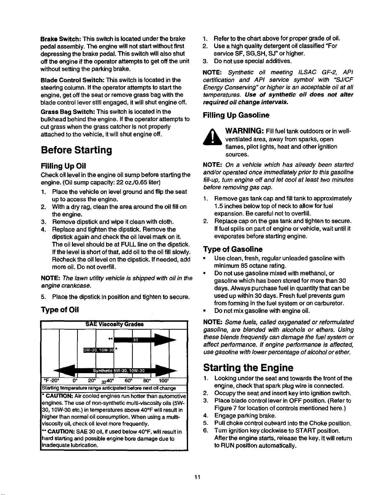
Type of Oil
SAE Viscosity Grades
lIll
_mi[llvdE_
°F -20 ° O° 20° 3240 ° 60_ 80° 100 °
3tading temperature range anticipated before next oil change
*CAUTION: Aircooledenginesrunhotterthanautomotive
_=ngines.The useofnon-syntheticmulti-viscosityoils(5W-
30,10W-30etc.)intemperaturesabove40°F willresultin
nigherthannormaloilconsumption.Whenusinga multi-
/iscosltyoil,checkoillevelmorefrequently.
'*CAUTION: SAE 30 oil,ifusedbelow40°F, willresultin
lard startingandpoesibleengineboredamagedue to
nadequatelubrication.
1. Refer tothe chart above for proper grade of oil.
2. Use a high quality detergent oil classified =For
service SF, SG,SH, SJ" or higher.
3. Do not use special additives.
NOTE: Synthetic oil meeting ILSAC GF-2, API
certification and API service symbol with "SJ/CF
Energy Conserving" or higher is an acceptable oil at all
temperatures. Use of synthetic off does not alter
required oil change intervals.
Filling Up Gasoline
WARNING: Fillfuel tank outdoors or in well-
ventilated area, away from sparks, open
flames, pilot lights,heat and other ignition
sources.
NOTE: On a vehicle which has already been started
and/or operated once immediately prior to thisgasoline
fill-up, turn engine off and let cool at least two minutes
before removing gas cap.
1. Remove gas tank cap and filltank to approximately
1.5 inches below top of neck to allow for fuel
expansion. Be careful not tooverfill.
2. Replace cap on the gas tank and tighten to secure.
If fuel spills on part of engine or vehicle, wait until it
evaporates before startingengine.
Type of Gasoline
• Use clean, fresh, regular unleaded gasoline with
minimum 85 octane rating.
• Do not use gasoline mixed with methanol, or
gasoline which has been stored for more than 30
days. Always purchase fuel in quantity that can be
used up within30 days. Fresh fuel prevents gum
from forming in the fuel system or on carburetor.
• Do not mix gasoline with engine oil.
NOTE: Some fuels, called oxygenated or reformulated
gasoline, are blended with alcohols or ethers. Using
these blends frequently can damage the fuel system or
affect performance. If engine performance is affected,
use gasoline with lower percentage of alcohol or ether.
Starting the Engine
1. Looking under the seat and towards the front ofthe
engine, check that spark plugwire is connected.
2. Occupy the seat and insert key intoignitionswitch.
3. Place blade control lever in OFF position. (Refer to
Figure 7 for locationof controls mentioned here.)
4. Engage parking brake.
5. Pull choke controloutward intothe Choke position.
6. Tum ignitionkey clockwise to START position.
After the engine starts, release the key. Itwill retum
to RUN position automatically.
11
NOTE: Do not hold the key in the START position for
longer than ten seconds at a time. Doing so may cause
damage toyour vehicle engine's electric starter.
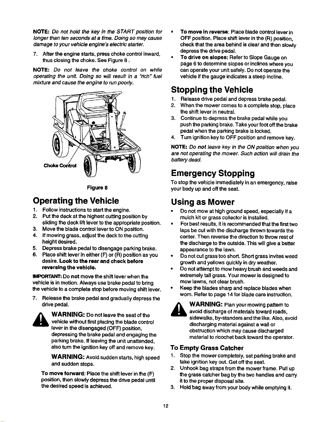
7. After the engine starts, press choke controlinward,
thus closing the choke. See Figure 8.
NOTE: Do not leave the choke control on while
operating the unit. Doing so will result in a "rich"fuel
mixture and cause the engine torunpoorly.
Figure 8
Operating the Vehicle
1. Followinstructionsto startthe engine.
2. Putthe deck at the highest cutting position by
slidingthe deck liftlever to the appropdate position.
3. Move the blade control lever to ON position.
4. If mowing grass, adjust the deck to the cutting
height desired.
5. Depress brake pedal to disengage parking brake.
6. Place shift lever in either (F')or (R) position as you
desire. Look to the rear and check before
reversing the vehicle.
IMPORTANT:Do not move the shiftlever when the
vehicle is in motion. Always use brake pedal tobdng
the vehicle to a complete stop before moving shift lever.
7. Release the brake pedal and gradually depress the
ddve pedal.
WARNING: Do not leave the seat of the
vehicle without first placing the blade control
lever in the disengaged (OFF) position,
depressing the brake pedal and engaging the
parking brake. If leaving the unitunattended,
also turn the ignition key off and remove key.
WARNING: Avoid sudden starts, high speed
and sudden stops.
To move forward: Place the shiftlever in the (F)
position, then slowly depress the ddve pedal until
the desired speed is achieved.
• To move in reverse: Place blade controllever in
OFF position. Place shift lever inthe (R) position,
check that the area behind isclear and then slowly
depress the drive pedal.
• To drive on slopes: Refer to Slope Gauge on
page 6 to determine slopes or inclineswhere you
can operate your unit safely. Do not operate the
vehicle ifthe gauge indicates a steep incline.
Stopping the Vehicle
1. Release drive pedal and depress broke pedal.
2. When the mower comes to a complete stop, place
the shift lever in neutral.
3. Continue to depress the brake pedal while you
pushthe parking brake. Take yourfoot offthe brake
pedal when the parking brake is locked.
4. Tum ignitionkeyto OFF positionand remove key.
NOTE: Do not leave key in the ON position when you
are not operating the mower. Such action willdrain the
battery dead.
Emergency Stopping
To stop the vehicle immediately in an emergency, raise
yourbody up and offthe seat.
Using as Mower
• Do not mow at high ground speed, especially ifa
mulch kit or grass collector is installed.
• Forbest results, itisrecommended that the firsttwo
laps be cut with the discharge thrown towards the
center. Then reverse the direction tothrow rest of
the discharge to the outside. This will give a better
appearance to the lawn.
• Do not cut grass too short. Short grass invites weed
growth and yellows quickly indry weather.
• Do not attempt to mow heavy brush and weeds and
extremely tall grass. Your mower isdesigned to
mow lawns, notclear brush.
Keep the blades sharp and replace blades when
worn. Refer to page 14 for blade care instruction.
WARNING: Plan your mowing pattem to
avoid discharge of materials toward reads,
sidewalks, by-standers and the like.Also, avoid
discharging material against a wall or
obstruction which may cause discharged
material to ricochet back toward the operator.
To Empty Grass Catcher
1. Stop the mower completely, set parking brake and
take ignitionkey out. Get offthe seat.
2. Unhook bag straps from the mower frame. Pull up
the grass catcher bag by the two handles and carry
itto the proper disposal site.
3. Hold bag away from your bodywhile emptying it.
12
4. Replace the bag on to the mower. Hook the loose
end of the bag retainer straps tothe vehicle frame
to secure the grass bag.
Using as Mulcher
This vehicle isshipped with a mulchplug to recirculate
grass clippings intothe lawn. The ultra-fineclippings
are forced back into the lawn where they act as a
natural fertilizer. Observe the followingfor best results:
• Attach the mulch plug to the cutting deck following
instructionson page 7.
• Never attempt to mulchif the lawn isdamp. Wet
grass tends to stickto the undemide of the cutting
deck preventing proper mulching ofthe clippings.
• Do notattempt to mulch more than 1/3 thetotal
height ofthe grass orapproximately 1-1/2 inches,
• Maintain a slow ground speed to allow the grass
clippingsmore time to be effectively mulched.
Using as Utility Cart
The lawn utilityvehicle, as itsname suggests, can be
used as botha ridinglawn mower and a utilitycart.
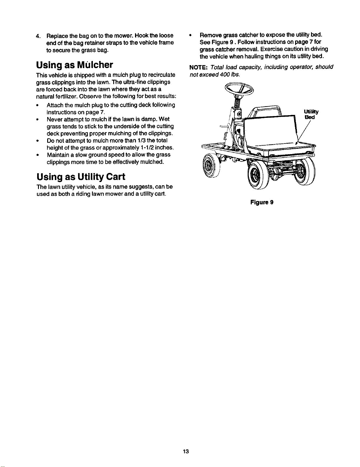
Remove grass catcher to expose the utilitybed.
See Figure 9, Follow instructionson page 7 for
grass catcher removal. Exemise caution in ddving
the vehicle when hauling things on itsutilitybed.
NOTE: Total load capacity, including operator, should
not exceed 400 Ibs.
Figure 9
13
General Recommendation
• Always observe safety ruleswhen performing any
maintenance.
• The warranty on this lawn utilityvehicle does not
cover items that have been subjected to operator
abuse or negligence. To receive fullvalue from the
warranty, operator must maintain the equipment as
instructed in this manual.
• We do not recommend the use ofpressure
washers or garden hose to clean yourunit. These
may cause damage to electrical components,
spindles, pulleys, beadngs or the engine. The use
of water may shorten life ofyour lawn utilityvehicle
and reduce its serviceability.
• Followthe schedule below to ensure best
performance by your lawn utilityvehicle.
Maintenance Schedule
Task to be performed Every 8 Every 25 At start of
hours of hours of season
operation operation
Engine:
Check oil level ./
Change oil
Service air cleaner e/
Service spark plug
Clean debris
Clean cooling fins _f
Equipment:
Clean equipment
Check/sharpen blade ,_
Lubricate pivot points
Lubricate front wheels ,_
Lubricate steering shaft _t
Check brake _f
Check condition of belts
Check tire pressure
Check battery fluid level ,_
_lb WARNING: Neverattemptanymaintenancejob without first disconnecting the spark plug
wire and grounding against the engine.
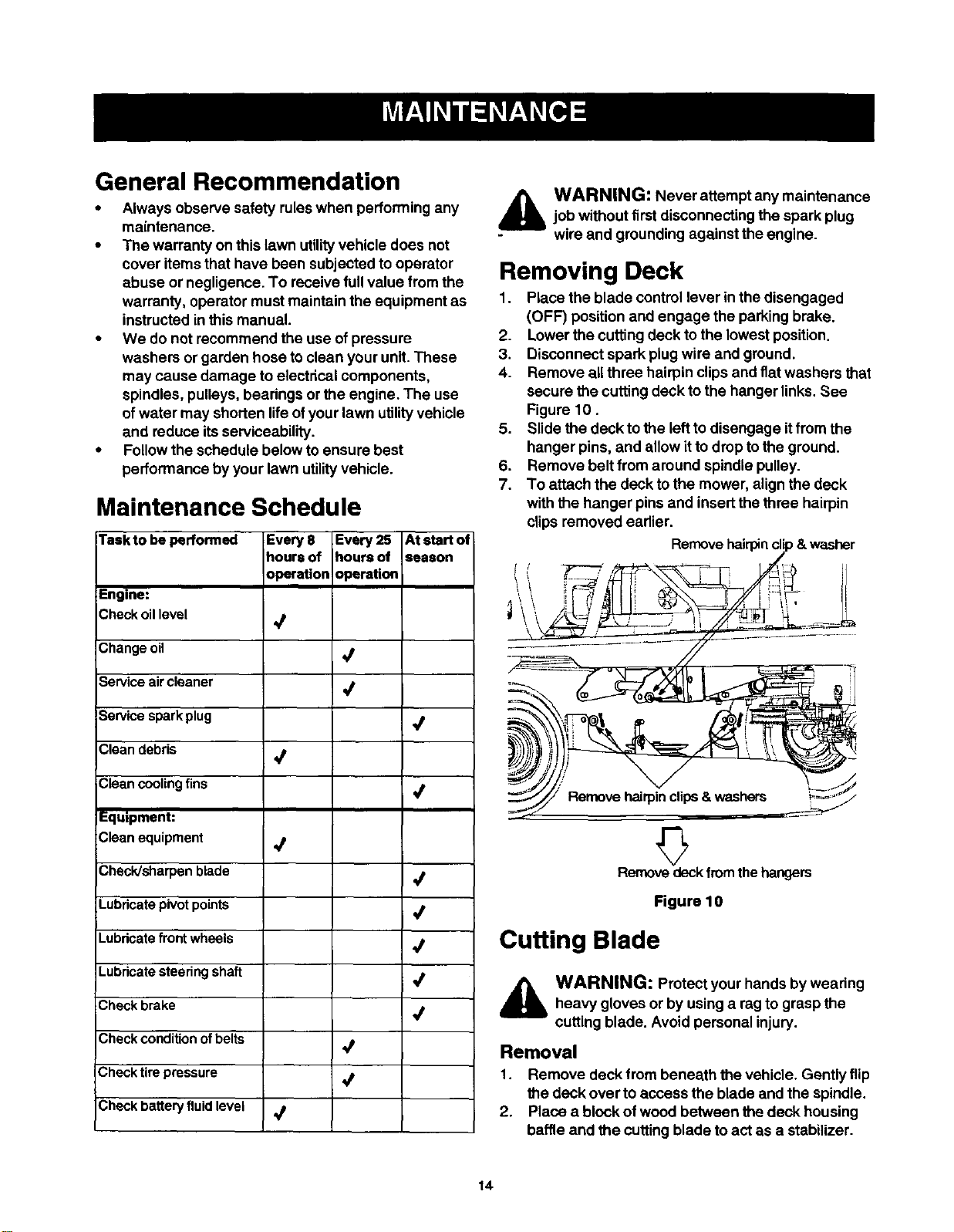
Removing Deck
1. Place the blade controllever inthe disengaged
(OFF) position and engage the parking brake.
2. Lower the cutting deck to the lowest position.
3. Disconnect spark plug wire and ground.
4. Remove all three hairpin clips and flat washers that
secure the cutting deck to the hanger links. See
Figure 10.
5. Slide the deck to the left to disengage it from the
hanger pins, and allow it to drop to the ground.
6. Remove belt from around spindle pulley.
7. To attach the deck to the mower, align the deck
with the hanger pins and insert the three hairpin
clips removed earlier.
Remove hairpin cl , & washer
Removedeckfromthe hangers
Figure 10
Cutting Blade
_lb ARNING: Protect your hands by wearing
heavy gloves or by using a rag to grasp the
cutting blade. Avoid personal injury.
Removal
1. Remove deck from beneath the vehicle. Gently flip
the deck over to access the blade and the spindle.
2. Piece a block of wood between the deck housing
baffle and the cutting blade to act as a stabilizer.
14
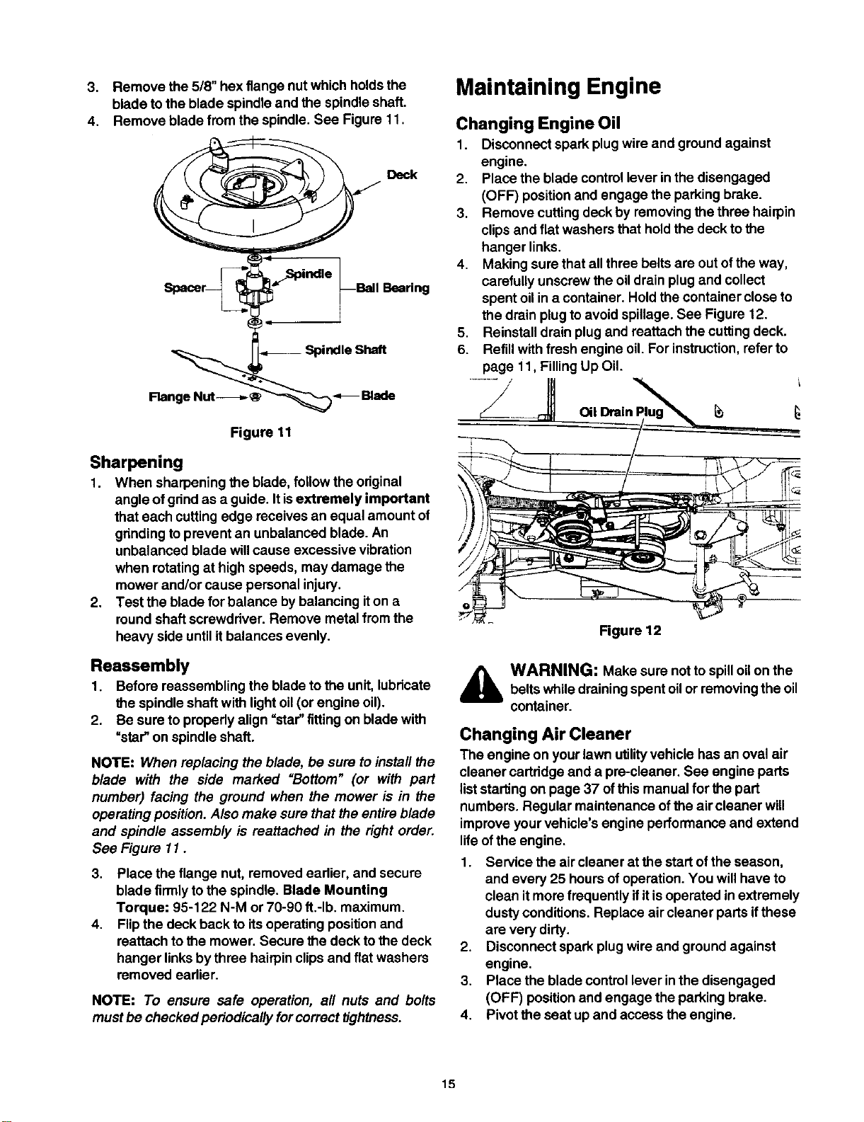
3. Remove the 5/8" hex flange nut which holds the
blade to the blade spindle and the spindle shaft.
4. Remove blade from the spindle. See Figure 11.
Ball _dng
Iq-
.,_ SpindleShaft
Flange Nut-___ Blade
Figure 11
Sharpening
1. When sharpening the blade, follow the original
angle of gdnd as a guide. It isextremely important
that each cutting edge receives an equal amount of
gnnding toprevent an unbalanced blade. An
unbalanced blade willcause excessive vibration
when rotatingat high speeds, may damage the
mower and/or cause personal injury.
2. Test the blade for balance by balancing iton a
roundshaft screwddver. Remove metal from the
heavy side until itbalances evenly.
Reassembly
1. Before reassembling the blade to the unit, lubdcate
the spindle shaft with light oil(or engine oil).
2. Be sure to propedy align "star"fittingon blade with
=star" on spindle shaft.
NOTE: When replacing the blade, be sure toinstall the
blade with the side marked =Bottom" (or with part
number) facing the ground when the mower is in the
operating position. Also make sure that the entire blade
and spindle assembly is reattached in the right order.
See Figure 11.
3. Place the flange nut, removed eadier, and secure
blade firmlytothe spindle. Blade Mounting
Torque: 95-122 N-M or 70-90 ft,-Ib, maximum.
4. Flipthe deck back to itsoperating position and
reattach to the mower. Secure the deck to the deck
hanger linksby three hairpinclips and flat washers
removed eadier.
NOTE: To ensure safe operation, all nuts and bolts
mustbe checked periodically forcorrect tightness.
Maintaining Engine
Changing Engine Oil
1. Disconnect spark plug wire and ground against
engine.
2. Place the blade control lever in the disengaged
(OFF) positionand engage the parking brake.
3. Remove cutting deck by removingthe three hairpin
clipsand flat washers that hold the deck to the
hanger links.
4. Making sure that all three belts are out ofthe way,
carefully unscrew the oildrain plug and collect
spent oil ina container. Hold the container close to
the drain plug to avoid spillage. See Figure 12.
5. Reinstall drain plug and reattach the cutting deck.
6. Refill with fresh engine oil. For instruction,refer to
page 11, Filling Up Oil.
Figure 12
,_ WARNING: Make sure not to spilloilon thebelts while drainingspent oilor removingthe oil
container.
Changing Air Cleaner
The engine on yourlawn utilityvehicle has an oval air
cleaner cartridge and a pre-cleaner. See engine parts
liststarting on page 37 of this manual for the part
numbers. Regular maintenance ofthe air cleaner will
improve your vehicle's engine performance and extend
life ofthe engine.
1. Service the air cleaner at the startof the season,
and every 25 hours ofoperation. You will have to
clean itmore frequently ifitis operated in extremely
dusty conditions. Replace air cleaner parts ifthese
are very dirty.
2. Disconnect spark plug wire and ground against
engine.
3. Place the blade control lever inthe disengaged
(OFF) positionand engage the parking brake.
4. Pivot the seat up and access the engine.
15
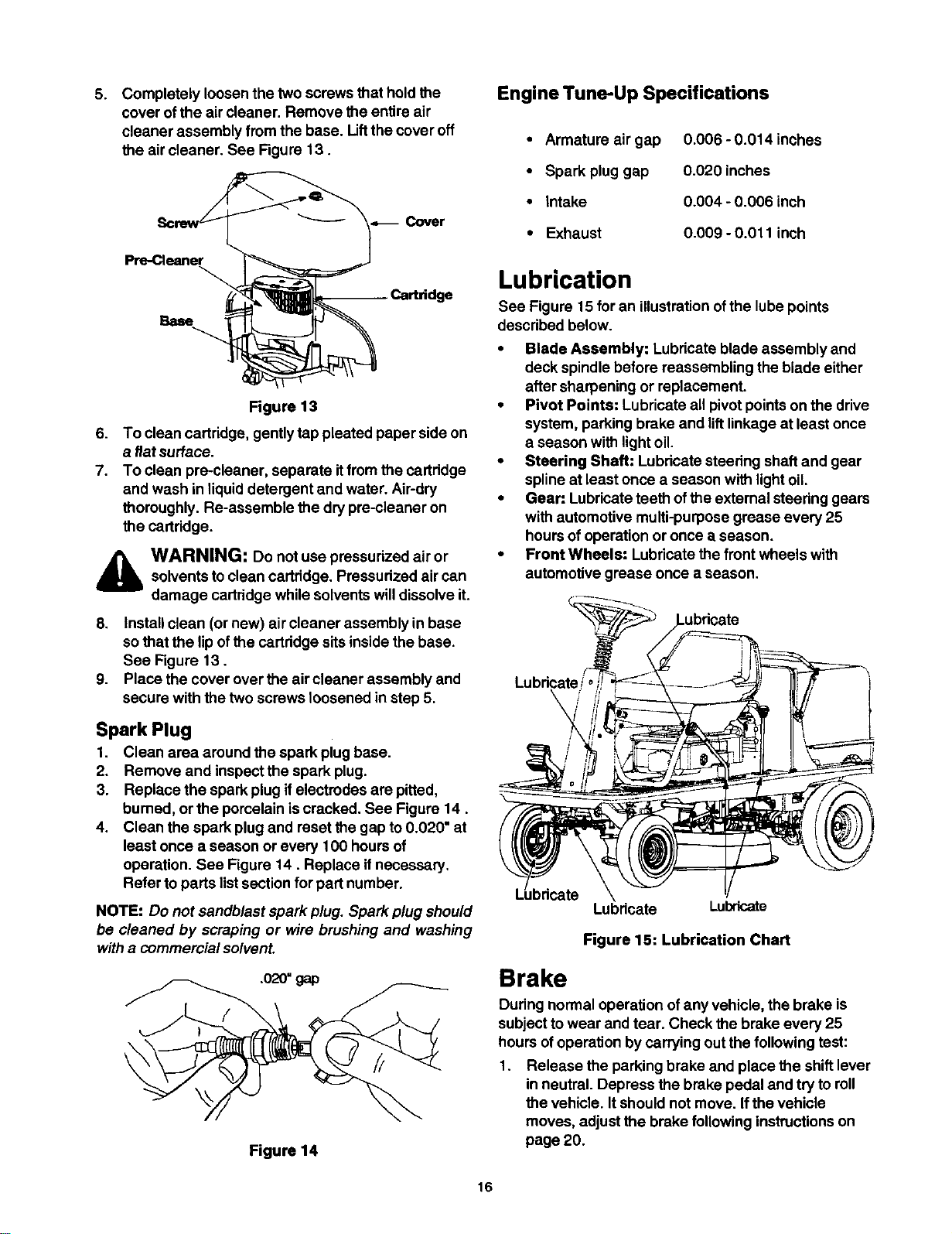
5.
Completely loosen the two screws that hold the
cover of the air cleaner. Remove the entire air
cleaner assembly from the base. Liftthe cover off
the air cleaner. See Figure 13.
Cover
Base
Figure 13
6. To clean cartridge, gently tap pleated paper side on
a flat surface.
7. To clean pre-cleaner, separate itfrom the cartridge
and wash in liquid detergent and water. Air-dry
thoroughly. Re-assemble the dry pre-cleaner on
the cartridge.
,_ WARNING: Do not use pressurized air orsolvents to clean cartridge. Pressurized air can
damage cartridge while solventswill dissolve it.
8. Install clean (or new) air cleaner assembly in base
so that the lipofthe cartridge sits inside the base.
See Figure 13.
9. Place the cover over the aircleaner assembly and
secure with the two screws loosened in step 6.
Spark Plug
1. Clean area around the spark plug base.
2. Remove and inspectthe spark plug.
3. Replace the spark plug if electrodes are pitted,
bumed, or the porcelain iscracked. See Figure 14.
4. Clean the spark plug and reset the gap to 0.020" at
least once a season or every 100 hours of
operation. See Figure 14. Replace if necessary.
Refer to parts listsection for part number.
NOTE: Do not sandblast spark plug. Spark plug should
be cleaned by scraping or wire brushing and washing
witha commercial solvent.
.020"gap
Figure 14
Engine Tune-Up Specifications
• Armature air gap
• Spark plug gap
• Intake
• Exhaust
0.006 - 0.014 inches
0.020 inches
0.004 - 0.006 inch
0.009 - 0.011 inch
Lubrication
See Figure 15 for an illustrationofthe lube points
described below.
• Blade Assembly: Lubricate blade assembly and
deck spindle before reassembling the blade either
after sharpening or replacement.
• Pivot Points: Lubricate all pivotpoints on the drive
system, parking brake and liftlinkage at least once
a season with light oil.
• Steering Shaft: Lubricate steedng shaft and gear
spline at least once a season with lightoil.
• Gear: Lubricate teeth of the external steering gears
with automotive multi-purpose grease every 25
hours of operation or once a season.
• Front Wheels: Lubricate the front wheels with
automotive grease once a season.
_ricete
Lubricate Lubricate
Figure 15: Lubrication Chart
Brake
During normal operation of any vehicle, the brake is
subject towear and tear. Check the brake every 25
hours of operation by carrying out the following test:
1. Release the parking brake and place the shift lever
in neutral. Depress the brake pedal and try to roll
the vehicle. It should not move. Ifthe vehicle
moves, adjust the brake following instructions on
page 20.
16
2. Set the parking brake and push the vehicle. Ifthe
rear wheels roll,adjust the brake following
instructionson page 20.
Tires
_lb ARNING: Never exceed maximum limitofair pressure shown on sidewall of the tire.
The recommended operating tire pressure is 20-22 psi
for both sets of tires. Refer to the tire sidewall for exact
tire manufacturer's recommendation. Do not
ovednflate. Uneven tire pressure could cause the
cutting deck to mow unevenly.
Battery
The battery is located under the cup holder to the right
ofthe seat. The positive battery terminal is marked Pos.
(+). The negative battery terminal ismarked Neg. (-).
_ ARNING: Battery posts, terminals and
related accessories contain lead and lead
compounds. Wash hands after handling.
• Always keep battery cables and terminals clean
and free of corrosive build-up.
• After cleaning, apply a lightcoat ofpetroleum jelly
or grease to bothterminals.
• Always keep the rubber boot positioned over the
positive terminal to prevent shorting.
• Ifremoving the battery for any reason, disconnect
the NEGATIVE (black) wire from itsterminal first,
followed by the POSITIVE (red) wire. When re-
installingbattery, always connect the POSITIVE
(red) wire to itsterminal first, followed by the
NEGATIVE (black) wire.
IMPORTANT:Be certain that wires are connected to the
correct terminals; reversing them could change poladty
and cause damage to the engine's alternating system.
• Check fluid level inside each cell of the battery
every two weeks and before and after charging.
Always maintain level just below the split rings.
• Add onlydistilled water. Never add additional acid
or any other chemicals tothe battery after initial
activation.
NOTE: ff you have operated the tractor for a long
period, check the fluid level of the battery as it can
overheat and lose fluid.
Connecting Battery Cables
To reconnect battery cables, ifthe battery was removed
for some reason, follow instructionsbelow.
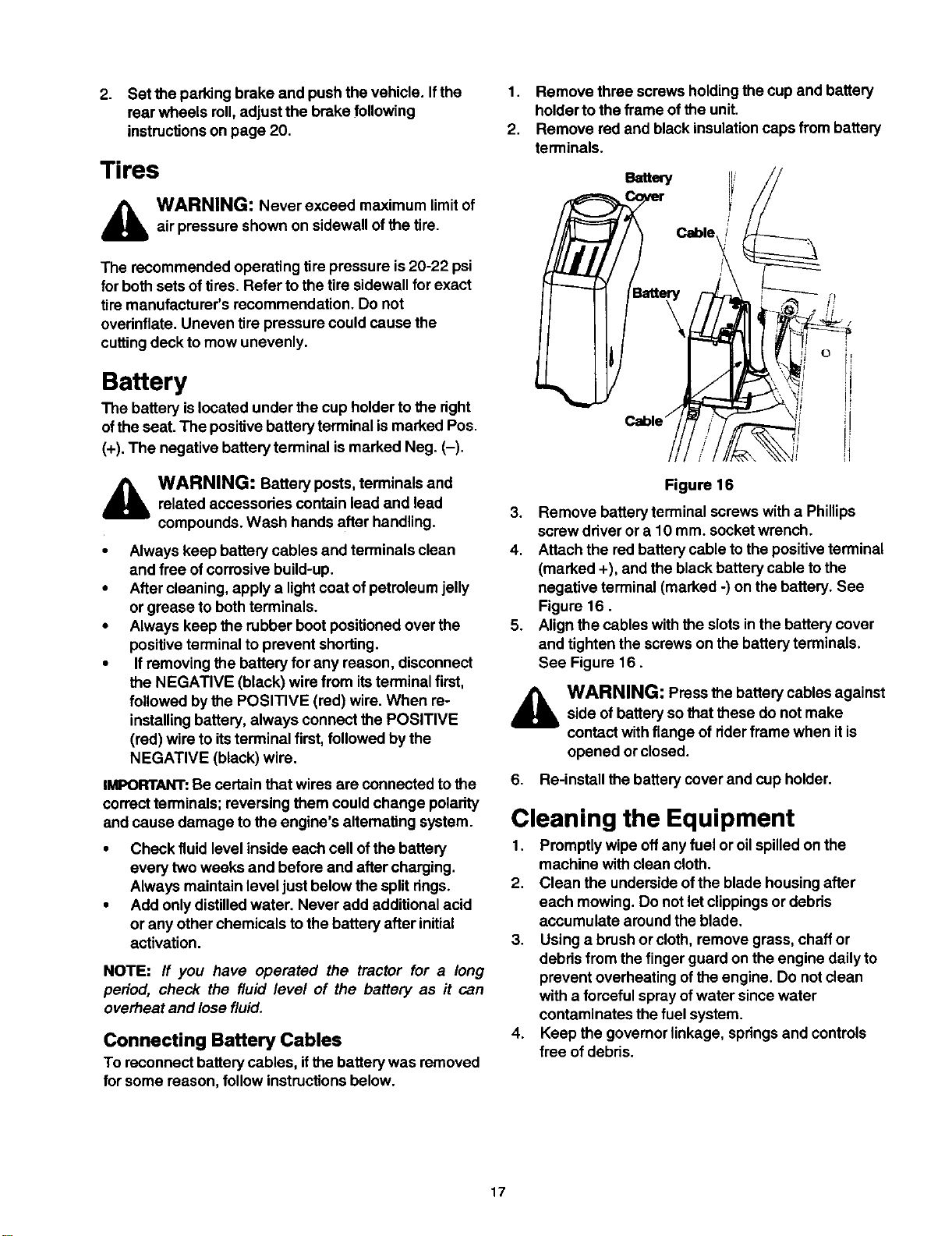
1.
2.
Remove throe screws holdingthe cup and battery
holderto the frame ofthe unit.
Remove red and black insulationcaps from battery
terminals.
_r !' //
l 1 \ Cable j
Figure 16
3. Remove battery terminal screws with a Phillips
screw driver or a 10 mm. socket wrench.
4. Attach the red battery cable tothe positive terminal
(marked +), and the black battery cable tothe
negative terminal (marked -) on the battery. See
Figure 16.
5. Align the cables with the slots inthe battery cover
and tighten the screws on the battery terminals.
See Figure 16.
WARNING: Press the battery cables against
side of battery sothat these do not make
contact with flange of riderframe when itis
opened or closed.
6. Re-install the battery cover and cup holder.
Cleaning the Equipment
1. Promptly wipe offany fuel or oilspilled on the
machine with clean cloth.
2. Clean the underside ofthe blade housing after
each mowing. Do not letclippings or debits
accumulate around the blade.
3. Using a brush or cloth, remove grass, chaff or
debds from the finger guard on the engine daily to
prevent overheating ofthe engine. Do not clean
with a fomeful spray of water since water
contaminates the fuel system.
4. Keep the governor linkage, springsand controls
free of debris.
17
WARNING: Never attempt any adjustment
whilethe engine is running, except where
specified in the operator's manual.
WARNING: For all other adjustments,
disconnect the spark plug wire(s) and ground
against the engine first. Then proceed with the
adjustment.
Adjusting Seat Position
The seat position on the lawn utilityvehicle can be
adjusted to maximize the operator's convenience.
1. Stop the vehicle completely and engage the
parking brake. Tum ignition off.
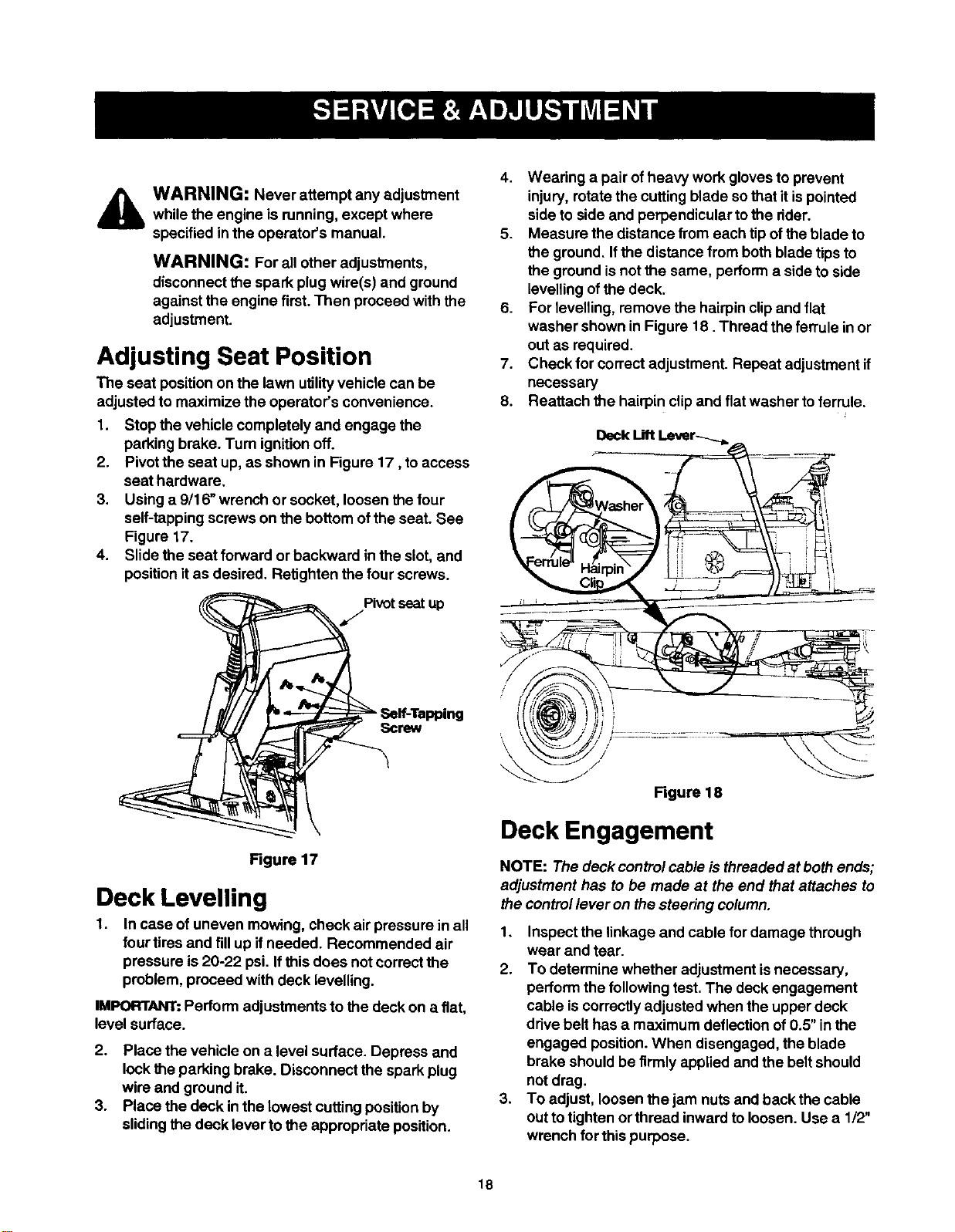
2. Pivot the seat up, as shown in Figure 17, to access
seat hardware.
3. Using a 9/16" wrench or socket, loosen the four
self-tapping screws on the bottom ofthe seat. See
Figure 17.
4. Slide the seat forward or backward in the slot,and
position itas desired. Retighten the four screws.
Figure 17
Deck Levelling
1. In case of uneven mowing, check air pressure in all
four tires and fillup ifneeded. Recommended air
pressure is20-22 psi. Ifthis does not correct the
problem, proceed with deck levelling.
IMPORTANT:Perform adjustments to the deck on a fiat,
level surface.
2. Place the vehicle on a level surface. Depress and
lock the parking brake. Disconnect the spark plug
wire and ground it.
3. Place the deck inthe lowest cutting position by
sliding the deck lever to the appropriate position.
4. Wearing a pair of heavy work gloves to prevent
injury, rotate the cutting blade sothat it ispointed
side to side and perpendicular to the dder.
5. Measure the distance from each tip of theblade to
the ground, If the distance from both blade tips to
the ground isnot the same, perform a side to side
levelling ofthe deck.
6. For levelling, remove the hairpin clipand flat
washer shown in Figure 18. Thread the ferrule in or
out as required.
7. Check for correct adjustment. Repeat adjustment if
necessary
8. Reattach the hairpin clipand flat washer toferrule.
Deck Lift Lever-_._ _ --_-
== • i !1
Ciip_ _ -_-__I.....
/[ I _ --- i.,r
,, \W%,,,,,,,,,_/// ,.................. _-,-__.
Figure 18
Deck Engagement
NOTE: The deck control cable isthreaded at bothends;
adjustment has to be made at the end that attaches to
the controllever on the steering column.
1. Inspect the linkage and cable for damage through
wear and tear.
2. To determine whether adjustment isnecessary,
perform the following test. The deck engagement
cable is correctly adjusted when the upper deck
drive belt has a maximum deflection of 0.5" inthe
engaged position.When disengaged, the blade
brake should be firmly applied and the belt should
not drag.
3. To adjust, loosen the jam nuts and back the cable
out totighten or thread inward to loosen. Use a 1/2"
wrench for this purpose.
18
4. Retighten jam nuts when proper tension is reached.
Test the adjustment. Readjust ifnecessary.
Jam Nut
Jam Nut
Deck Engagement
............ Cable
/
/
/
Figure 19
Adjusting Speed Control Rod
This adjustment is necessary when the vehicle cannot
hold the full range of speeds, or shows belt drag
(=creep")when the drive pedal is released.
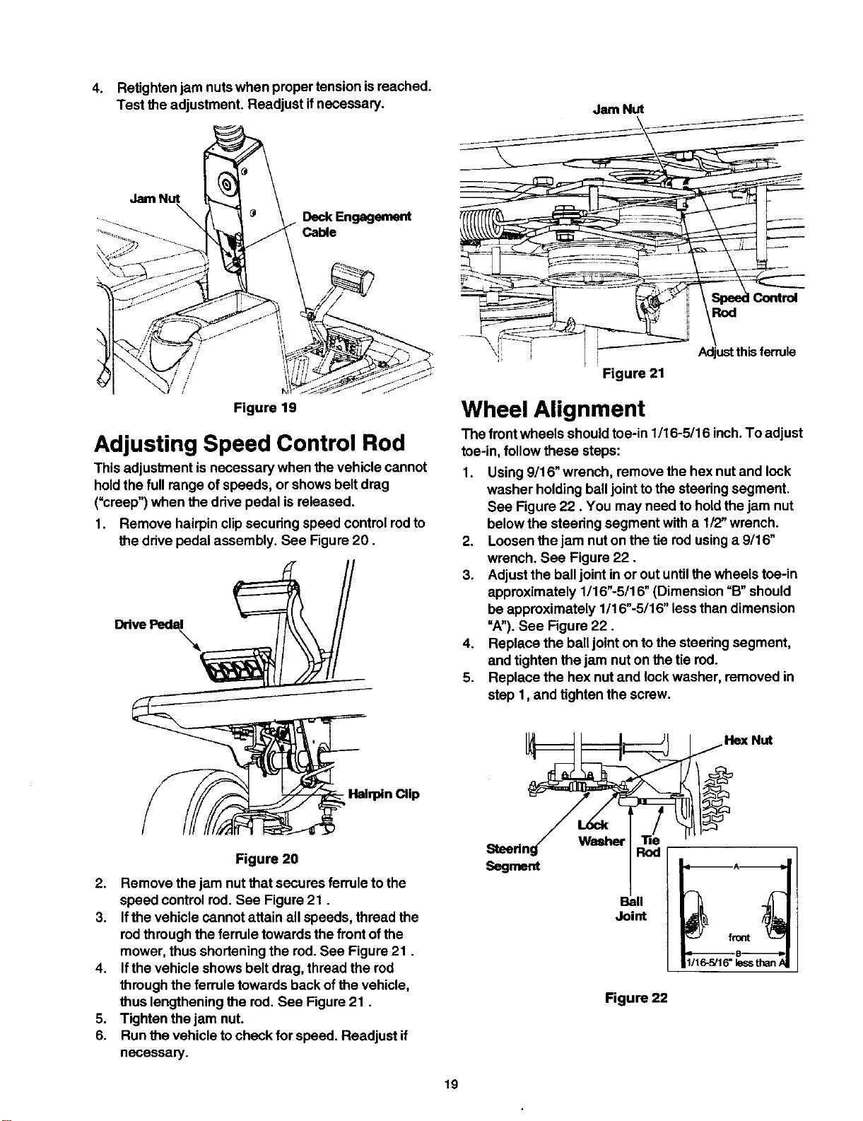
1. Remove hairpin clipsecudng speed control rodto
the drive pedal assembly. See Figure 20.
DrivePedal
\
Control
Rod
Figure 21
Adjust this ferrule
Wheel Alignment
The front wheels should toe-in 1/16-5/16 inch. To adjust
toe-in, follow these steps:
1. Using 9/16" wrench, remove the hex nut and lock
washer holding ball jointto the steedng segment.
See Figure 22. You may need to hold the jam nut
below the steering segment with a 1/2" wrench.
2. Loosen the jam nut on the tie red using a 9/16"
wrench. See Figure 22.
3. Adjust the balljoint in or out untilthe wheels toe-in
approximately 1/16"-5/16" (Dimension =B"should
be approximately 1/16"-5/16" less than dimension
=A").See Figure 22.
4. Replace the balljoint on to the steering segment,
and tighten the jam nut on the tie rod.
5. Replace the hex nut and lock washer, removed in
step 1, and tighten the screw.
Hex Nut
- Hairpin Clip
Figure 20
2. Remove the jam nut that secures ferrule to the
speed control rod. See Figure 21.
3. Ifthe vehicle cannot attain all speeds, thread the
rodthrough the ferrule towards the front ofthe
mower, thus shortening the rod. See Figure 21.
4. Ifthe vehicle shows belt drag, thread the rod
through the ferrule towards back of the vehicle,
thus lengthening the rod. See Figure21.
5. Tighten the jam nut.
6. Run the vehicle to check for speed. Readjust if
necessary.
Segment
Waeher
Rod
Ball
Joint
Figure 22
1/16-5/16"lessthan/
19
Adjusting Brake
A
WARNING: Do not adjust the brake while
engine isrunning. Be sureto blockthe wheels
ofthe vehicle before attempting any
adjustment on the brake cable.
NOTE: Adjustments are done at the cable end; for
adjustment of the calipers, see a Sears service center.
IMPORTANT:The brake cable should be adjusted so
that ithas a bit ofslack when the brake is released.
The frontcable bracket ismounted onthe frame behind
the pedal assembly. Both ends ofthe brake cable are
threaded; the longer threaded area at the pedal end
offers a wider range of adjustments.
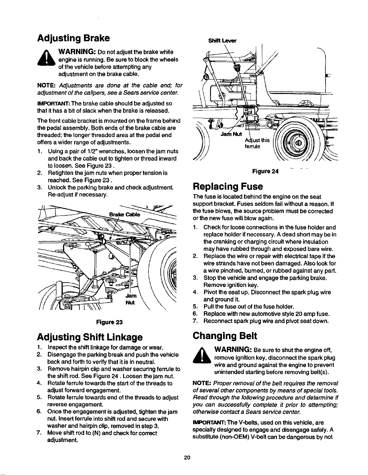
1. Using a pair of 1/2"wrenches, loosen the jam nuts
and back the cable out to tighten or thread inward
to loosen. See Figure 23.
2. RetJghtenthe jam nuts when preper tension is
reached, See Figure 23.
3. Unlock the parking brake and check adjustment.
Re-adjust if necessary.
Jam
Nut
Rgure 23
Adjusting Shift Linkage
1. Inspect the shift linkage for damage orwear.
2. Disengage the parking break and push the vehicle
back and forthto verify that it is in neutral.
3. Remove hairpin clipand washer securing ferrule to
the shift rod. See Figure 24. Loosen the jam nut.
4. Rotate ferrule towards the start ofthe threads to
adjust forward engagement.
5. Rotate ferrule towards end ofthe threads to adjust
reverse engagement.
6. Once the engagement is adjusted, tighten the jam
nut. Insert ferrule intoshift rodand secure with
washer and hairpin clip, removed in step 3.
7. Move shift rod to (N) and check for correct
adjustment.
Shift Lever
ferrule
Figure 24
Replacing Fuse
The fuse is located behind the engine on the seat
support bracket. Fuses seldom fail without a reason. If
the fuse blows, the source problem must be corrected
or the new fuse will blow again.
1. Check for loose connections in the fuse holder and
replace holder ifnecessary. A dead short may be in
the cranking or charging circuit where insulation
may have rubbed through and exposed bare wire.
2. Replace the wire or repair with electdcal tape if the
wire strands have not been damaged. Also lookfor
a wire pinched, burned, or rubbed against any part.
3. Stop the vehicle and engage the parking brake.
Remove ignition key.
4. Pivot the seat up. Disconnect the spark plug wire
and ground it.
5. Pull the fuse out of the fuse holder.
6. Replace with new automotive style 20 amp fuse.
7. Reconnect spark plug wire and pivot seat down.
Changing Belt
WARNING: Be sure to shut the engine off,
remove ignitionkey, disconnect the spark plug
wire and ground against the engine to prevent
unintended starting before removing belt(s).
NOTE: Proper removal of the belt requires the removal
ofseveral other components by means of special tools.
Read through the followingprocedure and determine if
you can successfully complete it prior to attempting;
otherwise contact a Sears service center.
IMPORTANT:The V-belts, used on this vehicle, are
specially designed to engage and disengage safely. A
substitute (non-OEM) V-belt can be dangerous by not
20
disengagingcompletely.Foraproperworkingmachine,
usebeltsavailablefromSears.
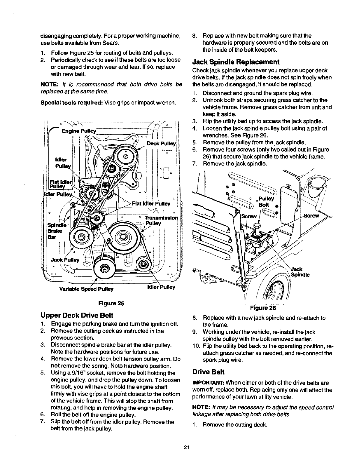
1.
2.
Follow Figure 25 for routing of belts and pulleys.
Periodically check to see ifthese belts are too loose
or damaged through wear and tear. If so, replace
with new belt.
NOTE: It is recommended that both drive belts be
replaced at the same time.
Special tools required: Vise grips or impact wrench.
_-- Engine Pulley
Idler
PulleyJ
FlatIdler X(
Spin
Brak _/f
Jack Pulley
" Transmissiol
Idlel
Figure 25
Upper Deck Drive Belt
I. Engage the parking brake and tum the ignitionoff.
2. Remove the cutting deck as instructedin the
previous section.
3. Disconnect spindle brake bar at the idler pulley.
Note the hardware positions for future use.
4. Remove the lowerdeck belt tension pulley arm. Do
not remove the spring. Note hardware position.
5. Using a 9/16" socket, remove the boltholdingthe
engine pulley, and drop the pulley down. To loosen
this bolt, you willhave to hold the engine shaft
firmly withvise grips at a point closest tothe bottom
ofthe vehicle frame. This will stopthe shaftfrom
rotating, and help in removing the engine pulley.
6. Roll the belt offthe engine pulley.
7. Slipthe belt offfrom the idler pulley. Remove the
belt from the jack pulley.
8. Replace with new belt making sure that the
hardware is propedy secured and the belts are on
the inside ofthe belt keepers.
Jack Spindle Replacement
Check jack spindle whenever you replace upper deck
drive belts. Ifthe jack spindle does not spinfreely when
the belts are disengaged, itshould be replaced.
1. Disconnect and ground the spark plugwire.
2. Unhook both straps securing grass catcher tothe
vehicle frame. Remove grass catcher from unitand
keep it aside.
3. Flip the utilitybed up to access the jack spindle.
4. Loosen the jack spindle pulley boltusing a pair of
wrenches. See Figure 26.
5. Remove the pulley from the jack spindle.
6. Remove four screws (only two called out in Figure
26) that secure jack spindle to the vehicle frame.
7. Remove the jack spindle.
_Pulley
Bolt
Spindle
Figure 26 ....
8. Replace with a new jack spindle and re-attach to
the frame.
9. Working under the vehicle, re-installthejack
spindle pulley with the bolt removed earlier.
10. Flip the utilitybed back tothe operating position, re-
attach grass catcher as needed, and re-connect the
spark plug wire.
Drive Belt
IMPORTANT:When either or bothof the drive belts are
wornoff, replace both. Replacing onlyone willaffect the
performance ofyour lawn utilityvehicle.
NOTE: It may be necessary toadjust the speed control
linkage after replacing both drive belts.
1. Remove the cutting deck.
21
2. Remove the upper drive belt first by workingfrom
the back ofthe unit. Roll the belt offthe idler pulley
first and then offthe transmission pulley. Next roll it
offthe variable speed pulley.
3. Working from the side of the unit, pullthe lower
drive belt tension pulley to the rightand rollthe
lower drive belt offthis pulley.
4. Using a 9/16 socket, remove the boltholdingthe
engine pulley, and drop the pulley down. To loosen
this bolt, you willhave to hold the engine shaft
firmly with vise grips at a pointclosest tothe bottom
, ofthe vehicle frame. This willstop the shaft from
rotating,and willfacilitate in removing the engine
pulley.
5. Remove the belt from the two idler pulleys.
6. Remove the belt from the variable speed pulley and
the transmission pulley.
7. Replace upper deck drive belts following earlier
instructions.
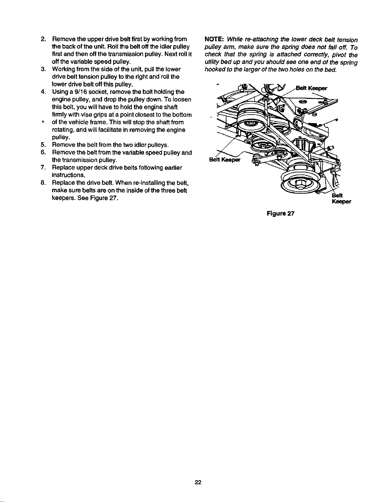
8. Replace the drive belt. When re-installing the belt,
make sure belts are on the inside of the three belt
keepers. See Figure 27.
NOTE: While re-attaching the lower deck belt tension
pulley ann, make sure the spring does not fall off. To
check that the spring is attached correctly, pivot the
utilitybed up and you should see one end of the spring
hooked to the larger ofthe twoholes on the bed.
Belt
Keeper
Figure 27
22
Ifthe lawn utilityvehicle isto be inoperative for a period
longerthan 30 days, follow the steps below for storage.
Preparing for Storage
Battery
1. Fully charge the battery with a 6 amp battery
charger. NEVER store battery without a fullcharge.
NOTE: ff a charger with 6 amp output is not available, a
lower output charger may be used for a longer period of
time. Do not charge the battery at a rate higher than 6
amps as it can damage the battery and reduce its life.
2. When storing unitfor extended periods, disconnect
battery cables and remove the battery from the unit.
3. Keep the terminals and the top of the battery clean
and free from corrosion. Clean the battery with
baking soda or a commercial battery cleaner.
IMPORTANT:Do not allow any cleaning solution to get
inside the battery.
Engine
1. To prevent gum from forming in fuel system or on
carburetor parts during storage, follow the
apprepriate step from those listed below:
a. Iffuel tank contains oxygenated or
reformulated gasoline (gasoline blended with
alcohol or ether), runengine untilthe gas
tank isdry.
b. Iffuel tank contains gasoline only, runengine
until the gas tank isdry.
c. If a gasoline additive isbeing added to the
gas, run engine for several minutes, after
adding, to circulate the additive through the
carburetor. Refer to page 11 for details on
additives.
2. While the engine is stillwarm, change oil. Refer to
instructionson page 15.
3. Remove spark plug and pour about 0.5oz. or 15mL
ofengine oilinto cylinder. Replace spark plug and
crank engine slowly todistribute the oil.
4. Remove any debris or grass clippingsfrom the
surface of the engine.
Equipment
1. Clean entire unitthoroughly.
2: Lubricate all pivotpoints, Wipe the entire machine
with an oiled rag toprotect the surfaces.
Storing the Equipment
1. Store unitin a clean, dry area. Do not store next to
corrosive materials, such as fertilizer.
2. When storingany type of power equipment in an
unventilated or metal storage shed, rustproofthe
equipment. Using a lightoil or silicone, coat the
equipment, especially any chains, springs,
beadngs and cables.
After Storage
The battery loses some ofitscharge each day when the
unit isnot used. Recharge battery before returning to
service or every two months, whichever occursfirst.
NOTE: If a charger is not available but the battery will
start the lawn utilib/ vehicle, the battery will be charged
by mowing for a minimum of one hour.
23
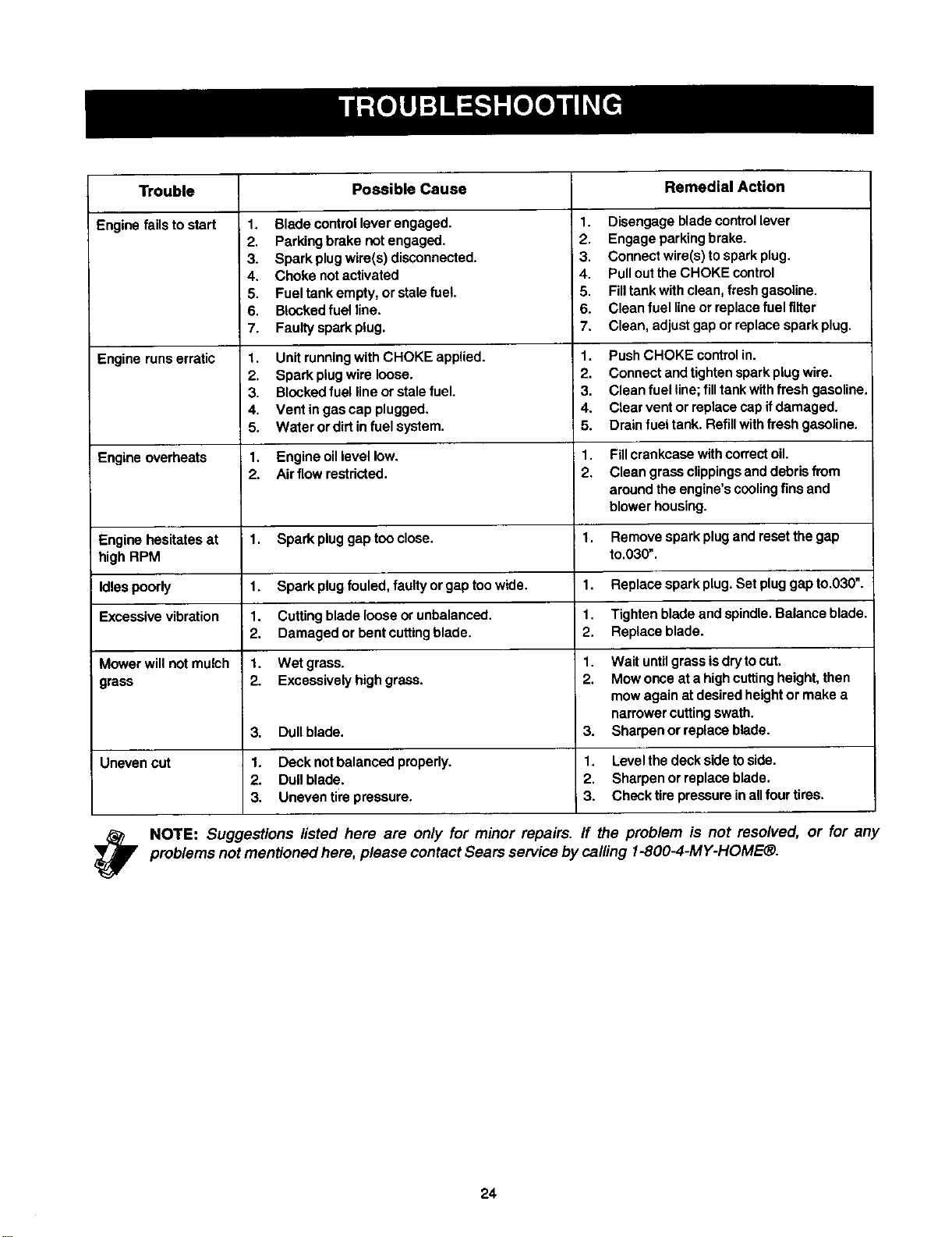
Trouble PossibleCause RemedialAction
Enginefailstostart
1. Blade control lever engaged.
2. Parking brake notengaged.
3. Spark plug wire(s) disconnected.
4. Choke not activated
5. Fuel tank empty, or stale fuel.
6. Blocked fuel line.
7. Faulty spark plug.
1. Disengage blade control lever
2. Engage parking brake.
3. Connect wire(s) to spark plug.
4. Pullout the CHOKE control
5. Filltank with clean, fresh gasoline.
6. Clean fuel line or replace fuel filter
7. Clean, adjust gap or replace spark plug.
Engine runs erratic 1. Unit running with CHOKE applied. 1. Push CHOKE controlin.
2. Spark plugwire loose. 2. Connect and tighten spark plug wire.
3. Blocked fuel line or stale fuel. 3. Clean fuel line;fill tank with fresh gasoline.
4. Vent in gas cap plugged. 4. Clear vent or replace cap ifdamaged.
5. Water or dirt in fuel system. 5. Drain fuel tank. Refill withfresh gasoline.
Engine overheats 1. Engine oil level low. 1. Fillcrankcase with correct oil.
2. Air flow restricted. 2. Clean grass clippings anddebris from
around the engine's cooling fins and
blower housing.
Engine hesitates at 1. Spark plug gap tooclose. 1. Remove spark plugend reset the gap
high RPM to.030".
Idles poorly 1. Spark plug fouled, faulty or gap too wide. 1. Replace spark plug. Set plug gap to.030".
Excessive vibration 1. Cutting blade loose or unbalanced, i 1. Tighten blade and spindle. Balance blade.
2. Damaged or bent cuttingblade. 2. Replace blade.
Mower will not mulch 1. Wet grass. 1. Wait untilgrass isdry to cut.
grass 2. Excessively high grass. 2. Mow once at a high cuttingheight, then
mow again at desired height or make a
narrower cuttingswath.
3. Dull blade. 3. Sharpen or replace blade.
Uneven cut 1. Deck not balanced properly. 1. Level the deck side to side.
2. Dull blade. 2. Sharpen or replace blade.
3. Uneven til'e pressure. 3. Check tire pressure in all four tires.
NOTE: Suggestions listed hero are only for minor repairs, ff the problem is not resolved, or for any
problems not mentioned here, please contact Sears service by calling 1-800-4-MY-HOME®.
24
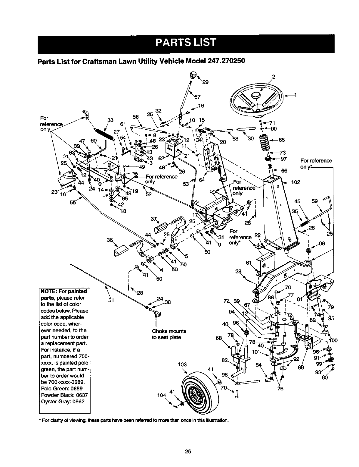
Parts List for Craftsman Lawn Utility Vehicle Model 247.270250
For
\ 33 15
\
only
only
For reference
45 59
3\
For
reference
only* \
NOTE: For painted
parts, please refer
to the list of color
codes below. Please
add the applicable
color code, wher-
ever needed, to the
part numbar to order
a replacement part.
For instance, if a
part, numbered 700-
xxxx, is painted polo
green, the part num-
ber to order would
be 700-xxxx-0689.
Polo Green: 0689
Powder Black: 0637
Oyster Gray: 0662
51
Chokemounts
toseat plate
103
'_ 41
104
\
76
• For cladty of viewing, these parts have been referred to more than once in this illustration.
25
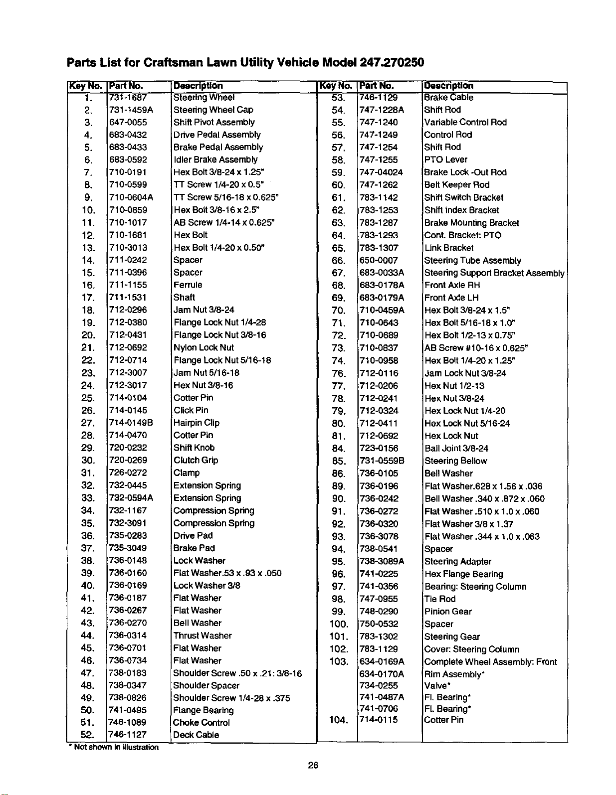
Parts List for Craftsman Lawn Utility Vehicle Model 247.270250
Key No. Part No.
1. 731-1687
2. 731-t459A
3. 647-0055
4. 683-0432
5. 683-0433
6. 683-0592
7. 710-0191
8, 710-0599
9, 710-0604A
10. 710-0859
11, 710-1017
12. 710-1681
13. 710-3013
14. 711-0242
15. 711-0396
16. 711-1155
17. 711-1531
18. 712-0296
19. 712-0380
20. 712-0431
21. 712-0692
22. 712-0714
23. 712-3007
24. 712-3017
25. 714-0104
26. 714-0145
27. 714-0149B
28. 714-0470
29. 720-0232
30. 720-0269
31. 726-0272
32. 732-0445
33. 732-0594A
34, 732-1167
35. 732-3091
36. 735-0283
37. 735-3049
38. 736.0146
39. 736-0160
40. 736-0169
41, 736-0187
42. 736-0267
43. 736-0270
44. 736-0314
45. 736-0701
46, 736-0734
47. 738-0183
48. 738-0347
49. 738,-0826
50. 741-0495
51. 746-1089
52. 746-1127
• Not shownin illustration
Description
Steedng Wheel
Steering Wheel Cap
Shift Pivot Assembly
Ddve Pedal Assembly
Brake Pedal Assembly
Idler Brake Assembly
Hex Bolt3/8-24 x 1.25"
]-r Screw 1/4-20 x 0.5"
TT Screw 5/16-18 x 0.625"
Hex Bolt3/8-16 x 2.5"
AB Screw 1/4-14 x 0.625"
Hex Bolt
Hex Bolt 1/4-20 x 0.50"
Spacer
Spacer
Ferrule
Shaft
Jam Nut 3/8-24
Flange Lock Nut 1/4-28
Flange Lock Nut 3/8-16
Nylon Lock Nut
Flange Lock Nut 5/16-18
Jam Nut 5/16-18
Hex Nut 3/8-16
Cotter Pin
Click Pin
Hairpin Clip
Cotter Pin
Shift Knob
Clutch Grip
Clamp
Extension Spring
Extension Spring
Compression Spring
Compression Spdng
Drive Pad
Brake Pad
Lock Washer
Flat Washer.53 x .93 x .050
Lock Washer 3/8
Flat Washer
Flat Washer
Bell Washer
Thrust Washer
Flat Washer
Flat Washer
Shoulder Screw ,50 x ,21 :3/8-16
Shoulder Spacer
Shoulder Screw 1/4-28 x .375
Flange Bearing
Choke Control
Deck Cable
Key No. Part No.
53. 746-1129
54. 747-1228A
55. 747-1240
56. 747-1249
57, 747-1254
58. 747-1255
59. 747-04024
60, 747-1262
61. 783-1142
62. 783-1253
63. 783-1287
64. 783-1293
65. 783-1307
66. 650-0007
67. 683-0033A
68. 683-0178A
69. 683-0179A
70. 710-0459A
71, 710-0643
72. 710-0689
73. 710-0837
74, 710-0958
76. 712-0116
77. 712-0206
78. 712-0241
79. 712-0324
80. 712-0411
81. 712-0692
84. 723-0156
85. 731-0559B
86. 736-0105
89. 736-0196
90. 736-0242
91. 736-0272
92. 736-032O
93. 736-3078
94. 738-0541
95. 738-3089A
96. 741-0225
97. 741-0356
98. 747-0955
99, 748-0290
100, 750-O532
101, 783-1302
102. 783-1129
103. 634-0169A
634-0170A
734-0255
741-0487A
741-0706
104. 714-0115
Oescription
Brake Cable
Shift Rod
Variable Control Rod
Control Rod
Shift Rod
PTO Lever
Brake Lock-Out Red
Belt Keeper Rod
Shift Switch Bracket
IShift Index Bracket
Brake Mounting Bracket
Cont. Bracket: PTO
Link Bracket
Steering Tube Assembly
Steering Support Bracket Assembly
Front Axle RH
Front Axle LH
Hex Bolt 3/8-24 x 1.5"
Hex Bolt 5/16-18 x 1,0"
Hex Bolt 1/2-13 x 0.75"
A.BScrew #10-16 x 0,625"
Hex Bolt 1/4-20 x 1.25"
Jam Lock Nut 3/8-24
Hex Nut 1/2-13
Hex Nut 3/8-24
Hex Lock Nut 1/4-20
Hex Lock Nut 5/16-24
Hex Lock Nut
Bail Joint 3/8-24
Steering Bellow
BellWasher
Flat Washer.628 x 1.56 x .036
BellWasher ,340 x ,872 x .060
Flat Washer .510 x 1.0 x .060
Flat Washer 3/8 x 1.37
Flat Washer ,344 x 1.0 x .063
Spacer
Steering Adapter
Hex Flange Bearing
Beadng: Steering Column
iTie Rod
PinionGear
Spacer
Steering Gear
3over: Steering Column
Complete Wheel Assembly: Front
Rim Assembly*
Valve*
FI.Bearing*
FI.Bearing*
Cotter Pin
26
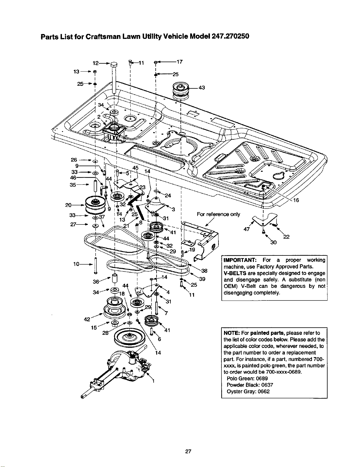
Parts List for Craftsman Lawn Utility Vehicle Model 247.270250
For reference only
/
16
11
IMPORTANT: For a proper working
machine, use Factory Approved Parts.
V-BELTS are specially designed to engage
and disengage safely. A substitute (non
OEM) V-Belt can be dangerous by not
disengaging completely.
14
NOTE: For painted parts, please refer to
the listof color codes below. Please add the
applicable color code, wherever needed, to
the part number to order a replacement
part. For instance, if a part, numbered 700-
xxxx, ispainted pologreen, the part number
to order would be 700-xxxx-0689.
Polo Green: 0689
Powder Black: 0637
Oyster Gray: 0662
27
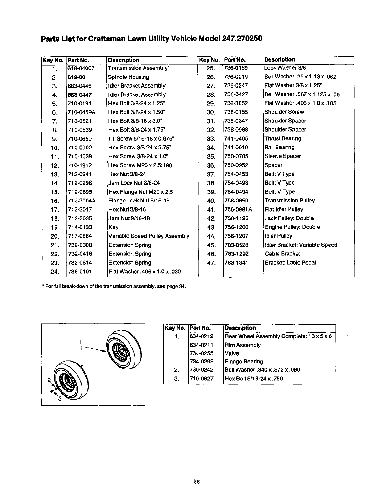
Parts List for Craftsman Lawn Utility Vehicle Model 247.270250
KeyNo.
1.
2.
3.
4.
5,
6.
7.
8.
9.
10.
11.
12.
13.
14.
15.
16.
17.
18.
19.
20.
21.
22.
23.
24.
Pert No,
618-04007
619-0011
683-0446
683-0447
710-0191
710-0459A
710-0521
710-0539
710-0650
710-0902
710-1039
710-1812
712-0241
712-0296
712-0695
712-3004A
712-3017
712-3035
714-0133
717-0884
732-0308
732-0418
732-0814
736-0101
Description Key No. Part No.
Transmission Assembly* 25. 736-0169
Spindle Housing 26. 736-0219
Idler Bracket Assembly 27. 736-0247
Idler Bracket Assembly 28, 736-0427
Hex Bolt3/8-24 x 1,25" 29, 736-3052
Hex Bolt3/8-24 x 1.50" 30. 738-0155
Hex Bolt 3/8-16 x 3,0" 31. 738-0347
Hex Bolt3/8-24 x 1,75" 32. 738-0968
TT Screw 5/16-18 x 0.875" 33. 741-0405
Hex Screw 3/8-24 x 3,75" 34. 741-0919
Hex Screw 3/8-24 x 1.0" 35. 750-0705
Hex Screw M20 x 2.5:180 36, 750-0952
Hex Nut 3/8-24 37. 754-0453
lam Lock Nut 3/8-24 38. 754-0493
Hex Flange Nut M20 x2.5 39. 754-0494
Flange Lock Nut 5/16-18 40. 756-0650
Hex Nut 3/8-16 41. 756-0981A
Jam Nut 9/16-18 42. 756-1195
Key 43. 756-1200
Variable Speed Pulley Assembly 44. 756-1207
Extension Spring 45. 783-0528
Extension Spring 46. 783-1292
Extension Spring 47. 783-1341
Flat Washer .406 x 1.0 x ,030
Description
Lock Washer 3/8
Bell Washer .39 x 1.13 x .062
Flat Washer 3/8 x 1.25"
BellWasher .567 x 1.128 x.06
Flat Washer .406 x 1.0 x. 105
Shoulder Screw
Shoulder Spacer
Shoulder Spacer
Thrust Bearing
Ball Bearing
Sleeve Spacer
Spacer
Belt: V Type
Belt:V Type
Belt:V Type
Transmission Pulley
Flat idler Pulley
Jack Pulley: Double
Engine Pulley: Double
Idler Pulley
Idler Bracket: Variable Speed
Cable Bracket
Bracket: Lock: Pedal
* For full break-down of the transmission assembly, see page 34.
Key No. Part No.
1, 634-0212
634-0211
734-0255
734-0298
2, 736-0242
3. 710-0627
Description
Rear Wheel Assembly Complete: 13 x 5 x6
Rim Assembly
Valve
Flange Bearing
Bell Washer .340 x ,872 x ,060
Hex Bolt5116-24 x .750
28
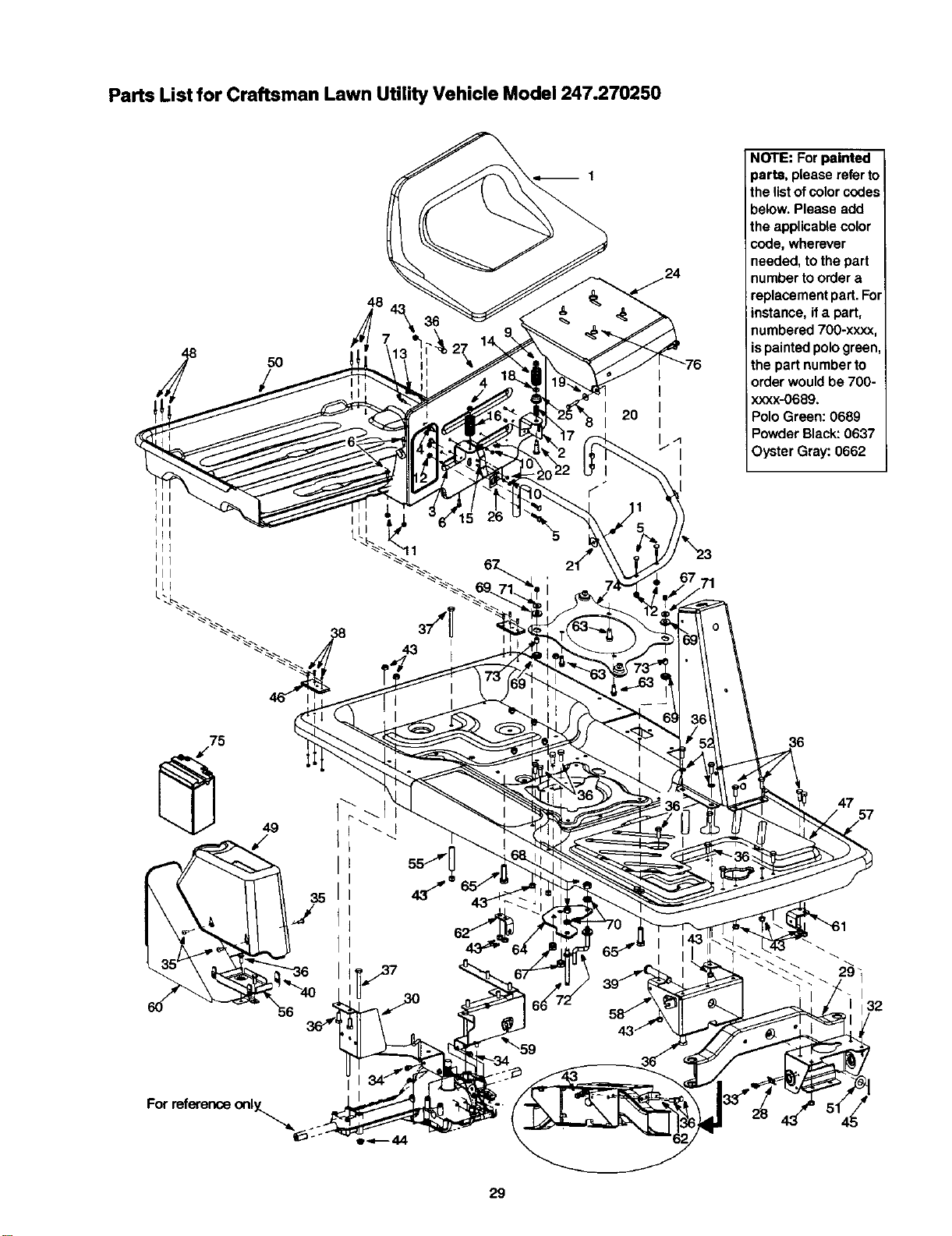
Parts List for Craftsman Lawn Utility Vehicle Model 247.270250
I
I
Iii
llq
111
III
IL_
5O
48
2O
I
I
I
I
I
NOTE: For painted
parts, please refer to
the listofcolor codes
below. Please add
the applicable color
code, wherever
needed, to the part
number to order a
replacement part. For
instance, if a part,
numbered 700-xxxx,
ispainted polo green,
the part number to
order would be 700-
xxxx-0689.
Polo Green: 0689
Powder Black: 0637
Oyster Gray: 0662
75
49
/
47
1
32
For reference only_
29
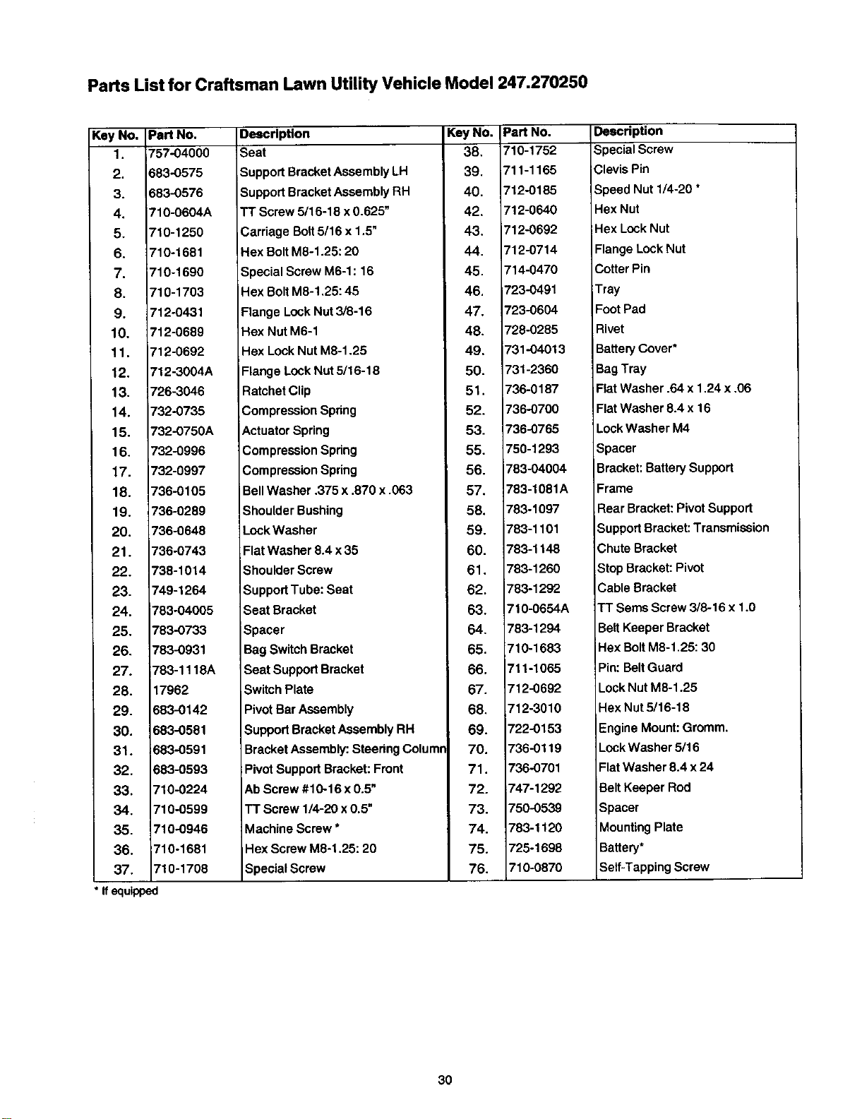
Parts List for Craftsman Lawn Utility Vehicle Model 247.270250
Key No. Pert No.
1. 757-04000
2. 683-0575
3. 683-0576
4. 710-0604A
5. 710-1250
6. 710-1681
7. 710-1690
8. 710-1703
9. 712-0431
10. 712-0689
11. 712-0692
12. 712-3004A
13, 726-3046
14. 732-0735
15. 732-0750A
16. 732-0996
17. 732-0997
18. 736-0105
19. 736-0289
20. 736-0648
21. 736-0743
22. 738-1014
23. 749-1264
24. 783-04005
25. 783-0733
26. 783-0931
27. 783-1118A
28. 17962
29. 683-0142
30. 683-0581
31. ;683-0591
32. 583-0593
33. 710-0224
34. 710-0599
35. 710-0946
36. 710-1681
37. 710-1708
* Ifequipped
Description
_eat
Support Bracket Assembly LH
Support Bracket Assembly RH
TT Screw 5/16-18 x 0.625"
Carriage Boll 5/16 x 1.5"
Hex BoltM8-1.25: 20
Special Screw M6-1:16
Hex Bolt M8-1,25: 45
Flange Lock Nut 3/8-16
Hex Nut M6-1
Hex Lock Nut M8-1.25
Flange Lock Nut 5/16-18
Ratchet Clip
Compression Spdng
Actuator Spring
Compression Spdng
Compression Spring
Bell Washer .375 x .870 x .063
Shoulder Bushing
Lock Washer
Flat Washer 8.4 x 35
Shoulder Screw
Support Tube: Seat
Seat Bracket
Spacer
Bag Switch Bracket
Seat Support Bracket
Switch Plate
Pivot Bar Assembly
Support Bracket Assembly RH
Bracket Assembly: Steedng Columr
Pivot Support Bracket: Front
Ab Screw #10-16 x 0.5"
TT Screw 1/4-20 x 0.5"
Machine Screw *
Hex Screw M8-1.25:20
Special Screw
KeyNo.
38,
39.
40.
42.
43.
44.
45.
46.
47.
48.
49.
50.
51.
52.
53.
55.
56.
57.
58.
59.
60.
61.
62.
63.
64.
65.
66.
67.
68,
69.
70.
71.
72.
73.
74.
75.
76.
Part No.
710-1752
711-1165
'12-0185
712-0640
712-0692
712-0714
714-0470
723-0491
723-0604
728-0285
731-04013
731-2360
736-0187
736-0700
736-0765
750-1293
783-04004
783-1081A
783-1097
783-1101
783-1148
783-1260
783-1292
710-O654A
783-1294
710-1683
'11-1065
712-0692
712-3010
722-0153
736-0119
736-0701
747-1292
750-0539
783-1120
725-1698
710-0870
Description
Special Screw
Clevis Pin
Speed Nut 1/4-20 *
Hex Nut
Hex Lock Nut
Flange Lock Nut
Cotter Pin
Tray
Foot Pad
Rivet
Battery Cover*
Bag Tray
Flat Washer .64 x 1.24 x .06
Flat Washer 8.4 x 16
Lock Washer M4
Spacer
Bracket: Battery Support
Frame
Rear Bracket: Pivot Support
Support Bracket: Transmission
Chute Bracket
Stop Bracket: Pivot
Cable Bracket
TT Seres Screw 3/8-16 x 1.0
Bell Keeper Bracket
Hex Bolt M8-1.25: 30
Pin: Belt Guard
Lock Nut M8-1.25
Hex Nut 5/16-18
Engine Mount: Gromm.
LockWasher 5/16
Flat Washer 8.4 x 24
Belt Keeper Rod
Spacer
Mounting Plate
Battery*
Self-Tapping Screw
30
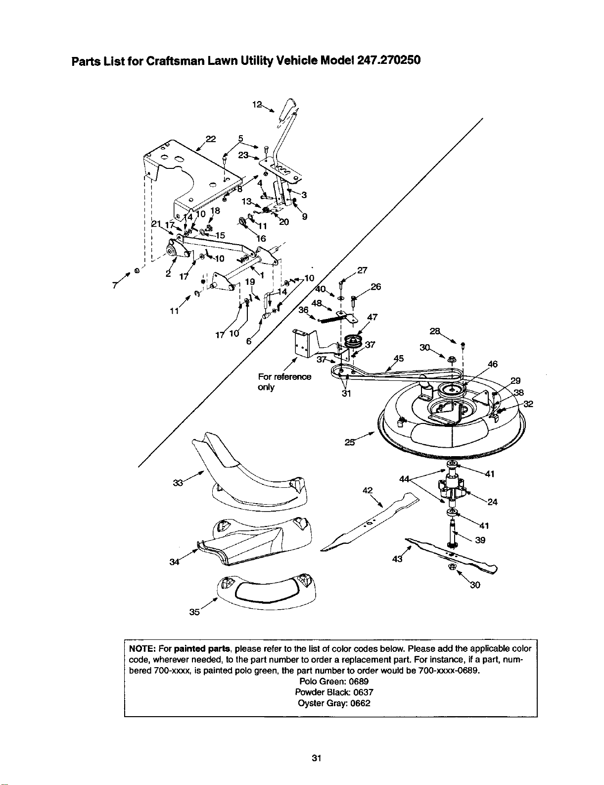
Parts List for Craftsman Lawn Utility Vehicle Model 247.270250
5
J
/
11
For reference
only
47
31
46
42
43
NOTE: For painted parts, please refer to the list of color codes below. Please add the applicable color
code, wherever needed, to the part number to order a replacement part. For instance, if a part, num-
bered 700-xxxx, is painted polo green, the part number to order would be 700-xxxx-0689.
Polo Green: 0689
Powder Black: 0637
Oyster Gray: 0662
31

Parts List for Craftsman Lawn Utility Vehicle Model 247.270250
Key No. Part No.
1. 683-0441
2, _83..0442
3. _83-0448
4, 710-0641
5. 710-1681
6. 711-0832
7. 712-0431
8. 712-0692
9. 712-3027
10. 714-0104
11. 716-0106
12. 731-2509
13. 732-1020
14. 736-0314
15. 736.-0336
16. 736-0341B
17. 736-3010
18. 738-0281
19. 747-1247
20. 750-0566A
21. 783-1136
22. 783-1138
23, 783-1143
24. 619-0020
Description Key No. Part No.
Shift Assembly: Front Lift 25. 783-1082
Pivot Bracket Assembly 26. 710-0347
Bracket Assembly: Lift Handle 27. 710-0514
Hex Bolt1/4-20 x 2.25 28, 710-0650
Hex BoltM8-1,25: 20 30. 712-0417A
Ferrule 31. 712-3017
Flange Lock Nut3/8-16 32. 726-0365
Hex Lock Nut M8-1.25 33. 731-2361A
Lock Nut 1/4-20 34. 731-2477
Hairpin Clip 35. 731-2505
E-Ring 36. 732-0814
Handle Grip 37. 736-0169
Torsion Spring 38, 736-0701
Thrust Washer .375 x .70 x .030 39, 738-0933
Flat Washer 5/8 x 1.0 x .030 40, 738-0968
Flange Washer ,633 x .883 41. 741-0919
Flat Washer ,407 x ,812 x.135 42. 742-0667
Shoulder Screw .625 x. 17:3/8-16 43. 742-0760
LiftLink 44. 750-1000
Spacer 45. 754-0495
Upper Lift Link Bracket 46. 756-0969
LiftHanger Bracket 47. 756-0981A
LiftIndx. Bracket 48, 783-1122
Spindle Housing
Description
Deck
Hex Screw 3/8-16 x 1.75
Hex Bolt3/8-16 x 1.0
"17"Screw 5/16-18 x 0,875
Flange Nut 5/8-18
Hex Nut 3/8-16
Speed Nut
Grass Catcher Chute
Side-Discharge Chute
Mulch Plug
;Extension Spring
Lock Washer
Flat Washer 8.4 x 24
Spindle Shaft
Shoulder Spacer
Ball Bearing
Blade: Bagging
Blade: 3-in-1
Spacer
Belt: V Type
Deck Pulley
Flat Idler Pulley
Idler Bracket: Deck
32
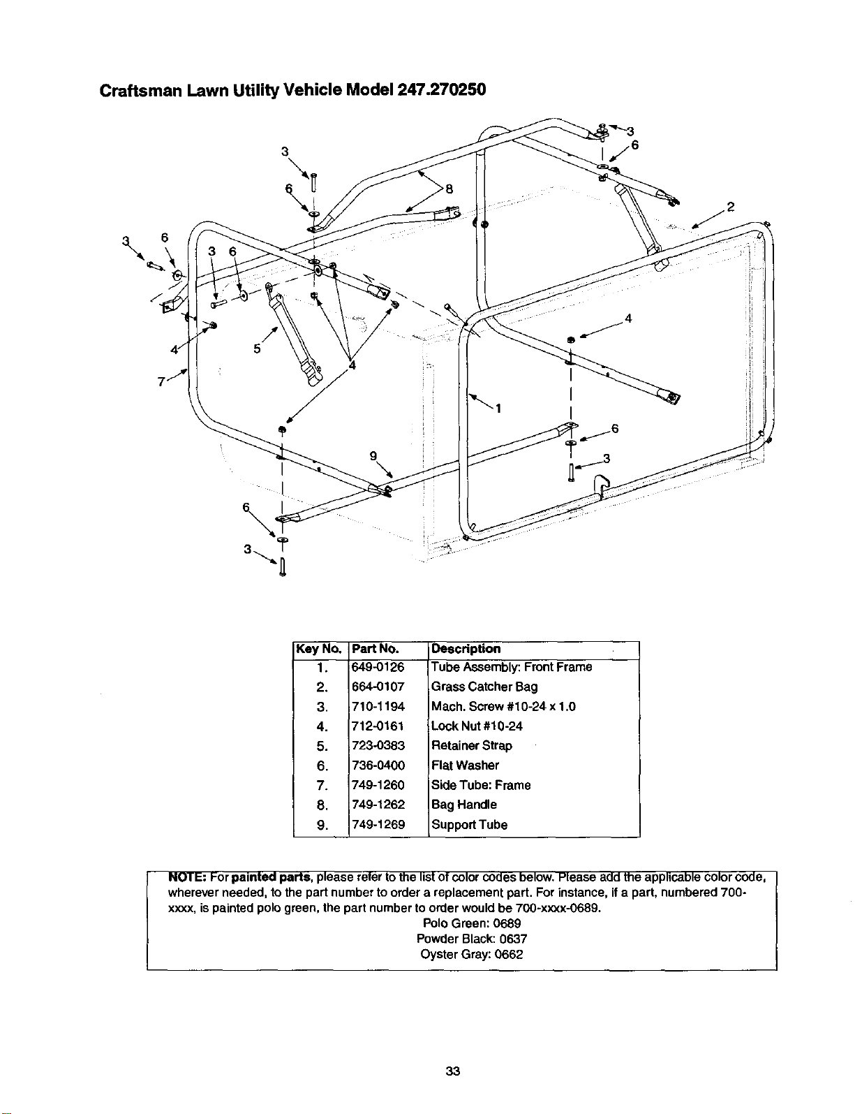
Craftsman Lawn Utility Vehicle Model 247.270250
3
\
I
I
j6
Key No. Part NO.
1. 649-0126
2. 664-0107
3. 710-1194
4. 712-0161
5. 723-0383
6. 736-0400
7. 749-1260
8. 749-1262
9. 749-1269
Description
Tube Assembly: Front Frame
Grass Catcher Bag
Mach. Screw #10-24 x 1.0
Lock Nut #10-24
Retainer Strap
Flat Washer
Side Tube: Frame
Bag Handle
Support Tube
NOTE: For painted parts, please refer tothe listof colorcodes below. Please add the applicable color code,
wherever needed, to the part number to order a replacement part. For instance, if a part, numbered 700-
xxxx, is painted polo green, the part number to order would be 700-xxxx-0689.
Polo Green: 0689
Powder Black: 0637
Oyster Gray: 0662
33
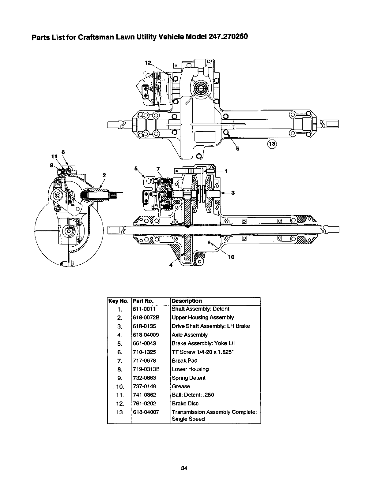
Parts List for Craftsman Lawn Utility Vehicle Model 247.270250
2
/
1
®
I0
KeyNo.
1.
2.
3.
4.
5.
6.
7.
8.
9.
10.
11.
12.
13.
Part No.
611-0011
618-0072B
610-0135
610-04009
661-0043
710-1325
717-0678
719-0313B
732-0863
737-0148
741-0862
761-0202
618-04007
Description
Shaft Assembly: Detent
Upper Housing Assembly
Drive Shaft Assembly: LH Brake
Axle Assembly
Brake Assembly: Yoke LH
TT Screw 1/4-20 x 1.625"
Break Pad
Lower Housing
Spring Detent
Grease
Ball: Detent: .250
Brake Disc
Transmission Assembly Complete:
Single Speed
34
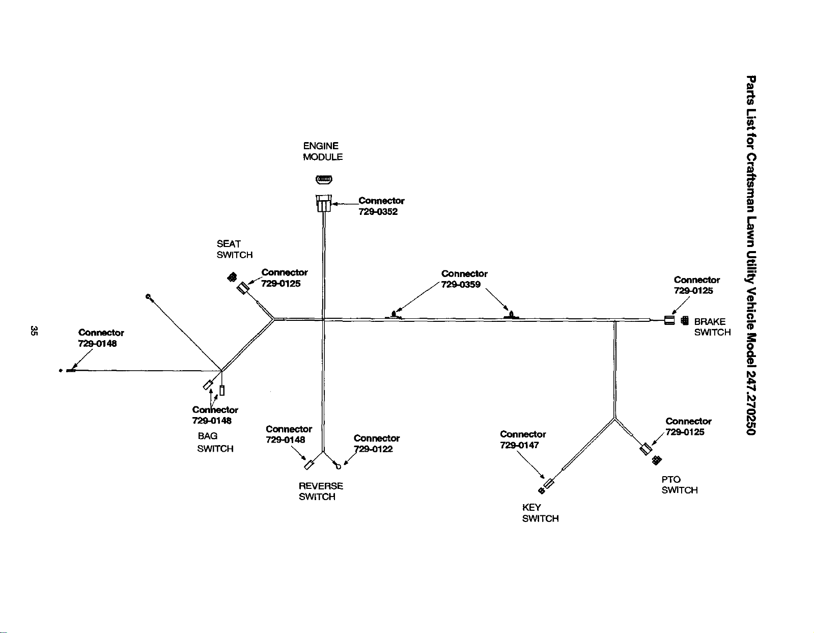
SEAT
SWITCH
7"_-0148
BAG
SWITCH
E
ENGINE 0
MODULE (1
u 729-0352 _
_ Connector Connector _
125 7L_.._59 Connector
JL
' - " _-_ a BRAKE
SWITCH _
I
o
'M
C_n_r O
Connector
729-0148 Connector Connector 125 0
7290147
Connector
729-0148
.J
REVERSE
SWITCH
PTO
SWITCH
KEY
SWITCH
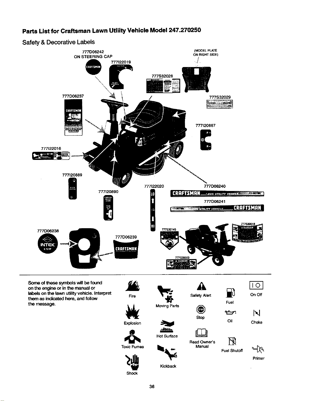
Parts List for Craftsman Lawn Utility Vehicle Model 247.270250
Safety & Decorative Labels
777D06237
777006242
ON STEERING CAP
777122019
777S32028
(MODEL PLATE
ON RIGHT SIDE)
777S32029
777122016
777120887
777D06238
@
777120889
|
777120890
777D06239
777122020 777D06240
777D06241
777S30018
Some of these symbols will be found
on the engine or in the manual or
labels on the lawn utility vehicle. Interpret
them as indicated here, and follow
the message,
Fire
Explosion
Toxic Fumes
Shock
Fuel
Moving Parts @
Stop
I'-,I
Oil Choke
Hot Surface
Read Owner's ]_
_1_ Manua, Fuel Shutoff '_
Primer
Kickback
36
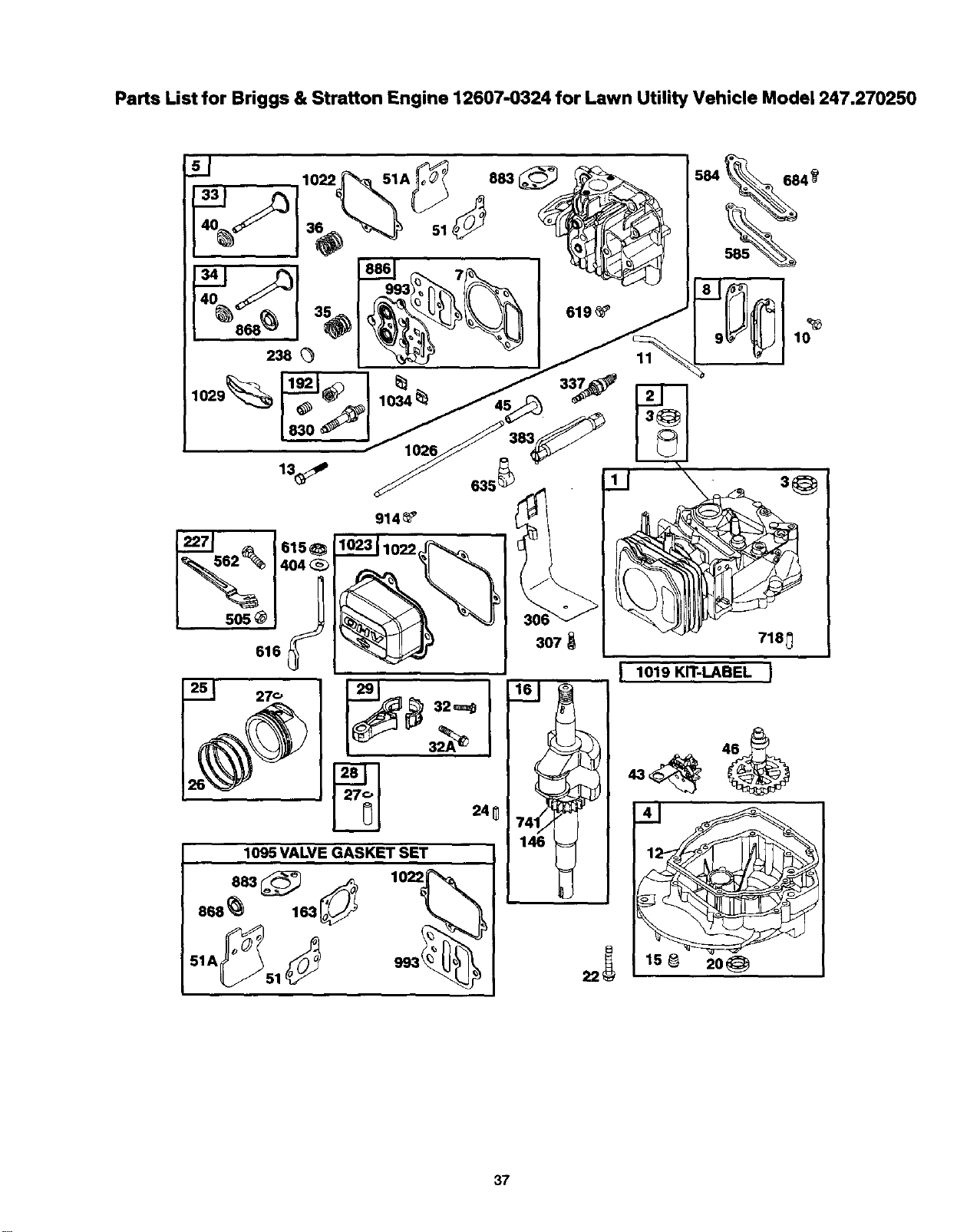
Parts List for Briggs & Stratton Engine 12607-0324 for Lawn Utility Vehicle Model 247.270250
684 9
238
1029_ _ 337_
1034
5o5@
914_
383
616
29 32,=q_
24_
1095 VALVE GASKET SET
883 (_ _ 1022
868_ 163_
307
10
718_
146
L 1019 KIT-LABEL J
15 _ 20_
37
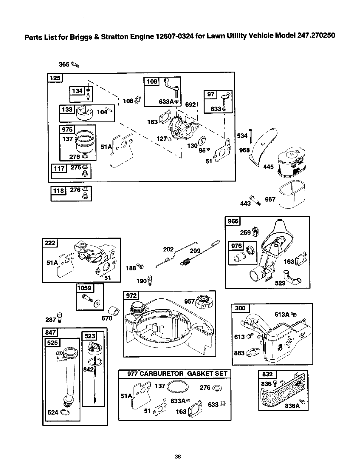
Parts List for Briggs & Stratton Engine 12607-0324 for Lawn Utility Vehicle Model 247.270250
365%
445_
524
188_
190_
977 CARBURETOR GASKET SET
"3A°s ?
sl _ 163_ 633®
_13_
883_
613A_
J\_836A _
38
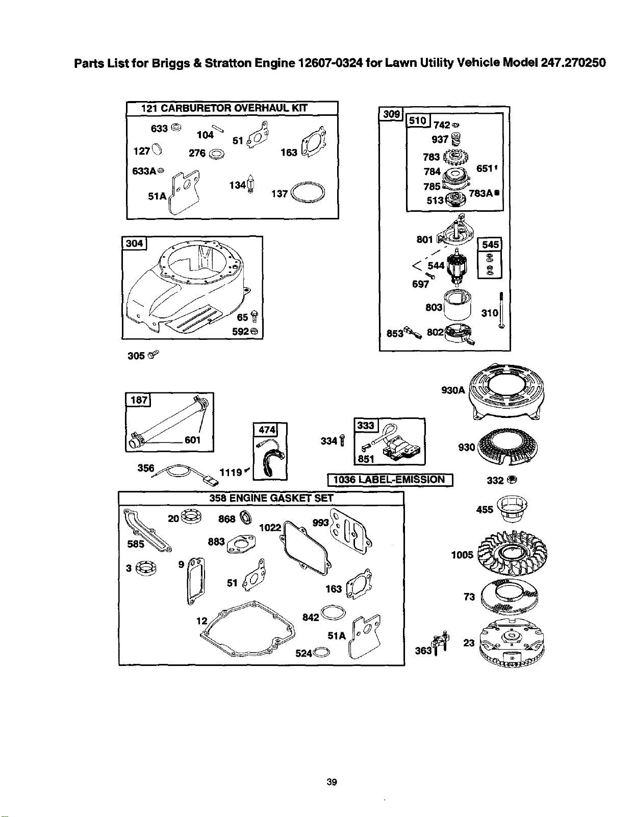
Parts List for Briggs & Stratton Engine 12607-0324 for Lawn Utility Vehicle Model 247.270250
121 CARBURETOR OVERHAUL KIT
6330 104_' 51_
127_ 276 _ 163
633A_
51A_ 134_ 1370
305_
309_ 5101742_
937_
784_ 651t
785_'_J_7" Aa
513_) oo
803_ 310_
553%502
I 1036 LABEL-EMISSION I
930A_
930_
332_
455@
1005_
39
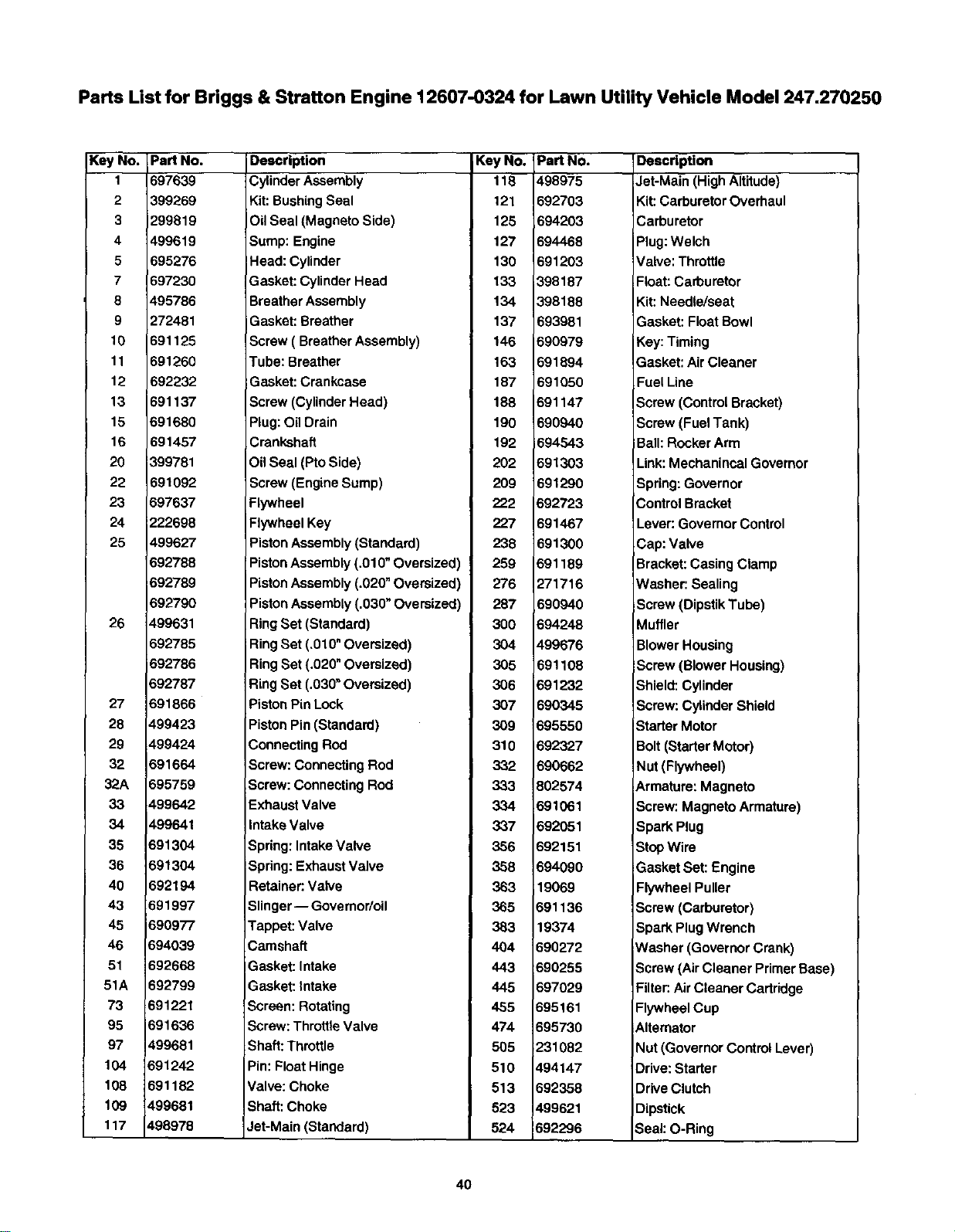
Parts List for Briggs & Stratton Engine 12607-0324 for Lawn Utility Vehicle Model 247.270250
Key No.
1
2
3
4
5
7
8
9
t0
11
12
13
16
16
20
22
23
24
25
26
27
28
29
32
32.A
33
34
35
36
4O
43
45
46
51
51A
73
95
97
104
108
109
117
PaN No.
897639
399269
299619
499619
695276
B97230
495786
272481
691125
B91260
692232
691137
691680
691467
399781
591092
697637
222698
499627
692788
B92789
692790
499631
692785
$92786
692787
691866
499423
499424
691664
695759
499642
499641
691304
691304
692194
691997
690977
694039
692668
692799
691221
691636
499681
691242
691182
499681
498978
Description Key No.
Cylinder Assembly 118
Kit: Bushing Seal 121
Oil Seal (Magneto Side) 125
Sump: Engine 127
Head: Cylinder 130
Gasket: Cylinder Head 133
Breather Assembly 134
Gasket: Breather 137
Screw ( Breather Assembly) 146
Tube: Breather 163
Gasket: Crankcase 187
Screw (Cylinder Head) 188
Plug: Oil Drain 190
Crankshaft 192
Oil Seal (Pto Side) 202
Screw (Engine Sump) 209
Flywheel 222
Flywheel Key 227
Piston Assembly (Standard) 238
Piston Assembly (.010" Oversized) 259
Piston Assembly (.020" Oversized) 276
Piston Assembly (.030" Oversized) 287
Ring Set (Standard) 300
Ring Set (.010" Oversized) 304
Ring Set (.020" Oversized) 305
Ring Set (.030" Oversized) 306
Piston Pin Lock 307
Piston Pin (Standard) 309
Connecting Rod 310
Screw: Connecting Rod 332
Screw: Connecting Rod 333
Exhaust Valve 334
Intake Valve 337
Spring: Intake Valve 356
Spring: Exhaust Valve 358
Retainer: Valve 363
Slinger-- Govemor/oil 365
Tappet: Valve 383
Camshaft 404
IGasket: Intake 443
Gasket: Intake 445
Screen: Rotating 455
Screw: Throttle Valve 474
Shaft: Throttle 505
Pin: Float Hinge 510
Valve: Choke 513
Shaft: Choke 523
Jet-Main (Standard) 524
IPart No.
1498975
592703
694203
594468
591203
_398187
398188
593981
590979
591894
691050
691147
590940
594543
591303
691290
592723
591467
691300
591189
271716
690940
594248
499676
691108
591232
590345
695550
892327
590662
802574
691061
692051
692151
694090
19069
691136
19374
690272
690255
697029
695161
695730
231082
494147
692358
499621
692296
Description
Jet-Main (High Altitude)
Kit: Carburetor Overhaul
Carburetor
Plug: Welch
Valve: Throttle
Float: Carburetor
Kit: Needle/seat
Gasket: Float Bowl
Key: Timing
Gasket: Air Cleaner
Fuel Line
Screw (Control Bracket)
Screw (Fuel Tank)
Ball: Rocker Arm
Link: Mechanincal Governor
Spring: Governor
Control Bracket
Lever: Governor Control
Cap: Valve
Bracket: Casing Clamp
Washer: Sealing
Screw (Dipstik Tube)
Muffler
Blower Housing
Screw (Blower Housing)
Shield: Cylinder
Screw: Cylinder Shield
Starter Motor
Bolt (Starter Motor)
Nut (Flywheel)
Armature: Magneto
Screw: Magneto Armature)
Spark Plug
Stop Wire
Gasket Set: Engine
Flywheel Puller
Screw (Carburetor)
Spark Plug Wrench
Washer (Governor Crank)
Screw (Air Cleaner Primer Base)
Filter: Air Cleaner Cartridge
Flywheel Cup
Alternator
Nut (Governor Control Lever)
Drive: Starter
Drive Clutch
Dipstick
Seal: O-Ring
40
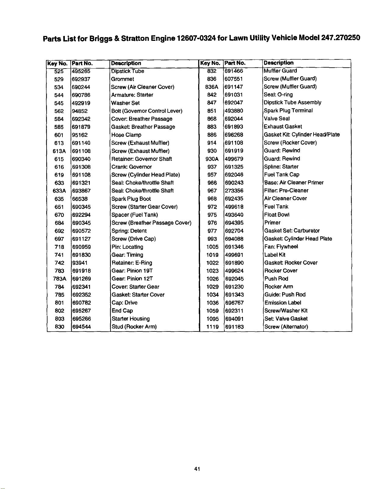
Parts List for Briggs & Stratton Engine 12607-0324 for Lawn Utility Vehicle Model 247.270250
Key No, Part No.
525 495265
529 692937
534 690244
544 690786
545 492919
562 94852
584 692342
585 691879
601 95162
613 691140
613A 691108
616 690340
616 691306
619 691108
633 691321
633A 693867
635 66538
651 690345
670 692294
684 690345
692 690572
697 691127
718 690959
741 691830
742 93941
783 691918
783A 691269
784 692341
785 692352
801 690782
802 695267
803 695266
830 694544
Description Key No. Part No.
Dipstick Tube 832 691466
Grommet 836 607551
Screw (Air Cleaner Cover) 836A 691147
Armature: Starter 842 691031
Washer Set 847 692047
Bolt(Governor Control Lever) 851 493880
Cover: Breather Passage 868 692044
Gasket: Breather Passage 883 691893
Ho6e Clamp 886 696268
Screw (Exhaust Muffler) 914 691108
Screw (Exhaust Muffler) 930 691919
Retainer: Governor Shaft 930A 499679
Crank: Governor 937 691325
Screw (Cylinder Head Plate) 957 692046
Seal: Choke/throttle Shaft 966 690243
Seal: Choke/throttle Shaft 967 273356
Spark Plug Soot 968 692435
Screw (Starter Gear Cover) 972 499618
Spacer (Fuel Tank) 975 493640
IScrew (Breather Passage Cover) 976 694395
Spring: Detent 977 692704
Screw (Ddve Cap) 993 694088
Pin: Locating 1005 691346
Sear: Timing 1019 499691
Retainer: E-Ring 1022 691890
Gear: Pinion 19T 1023 499624
Gear: Pinion 12T 1026 ._92045
Cover: Starter Gear 1029 691230
Gasket: Starter Cover 1034 1691343
Cap: Drive 1036 _96767
End Cap 1059 692311
Starter Housing 1095 594091
Stud (Rocker Arm) 1119 691183
Description
Muffler Guard
Screw (Muffler Guard)
Screw (Muffler Guard)
Seat: O-ring
Dipstick Tube Assembly
Spark Plug Terminal
Valve Seal
Exhaust Gasket
Gasket Kit: Cylinder Head/Plate
Screw (Rocker Cover)
Suard: Rewind
Guard: Rewind
Spline: Starter
Fuel Tank Cap
Base: Air Cleaner Primer
Filter: Pre-Cleaner
Air Cleaner Cover
Fuel Tank
Float Bowl
Primer
Gasket Set: Carburetor
Gasket: Cylinder Head Plate
Fan: Flywheel
Label Kit
Gasket: Rocker Cover
Rocker Cover
Push Rod
Rocker Arm
Guide: Push Rod
Emission Label
Screw/Washer Kit
Set: Valve Gasket
Screw (Alternator)
41
|ndice de materias Pdgina
Informacibn sobre la garantfa ................... 42
Prdcticas de funcionamiento seguras ...... 43
Determinacibn de la pendiente ................ 46
Monta}e..................................................... 47
Funcionamiento ........................................ 49
|ndice de materias Pdgina
Mantenimiento ........................................ 54
Servicio y ajustes ................................... 58
Almacenamiento prolongado.................. 62
Resoluci6n de problemas ....................... 63
Informacidn de la ayuda de cliente......... 64
GARANT[A LIMITADA SOBRE ELVEH[CULO UTILITARIO CORTACI_SPED
Pot dos (2) afios a partir de la fecha de compra, sial equipo de monta e Craftsman se le da mantenimiento, lubricacibn y
afinacidn de acuerdo con las instmcciones en el manua del prop etario, Sears reparard o reemp azard libre de cargo
cualquier pieza que est6 defectuosa en material y mano de obra de acuerdo con la gufa de cobertura que se describe rods
abajo.
Sears proporcionard tambidn sin costo en la mano de obra aqueUas piezas en garantia por losdos afios cornpletos. Durante
los primeros 30 dfas a partir de la fecha de compra, no habrd cargos por dar servicio al producto en su domicillo para aquello
que est_ cubierlo en esta garantl'a. (Vea las excepciones rods abajo).
Para su conveniencia, el servicio de garantfa EN SU CASA estard disponible despu_Ysde los primeros 30 dfas de la fecha de
compra, pero se le hard un cargo por gastos de transporte. Este cargo no se realizard si el producto Craftsman se Ileva hasta
un osntro autorizado de Sears. Para conocer el centro autorizado Sears m_s carcano, por favor Ilame al 1-800-4-MY-
Home(r). Esta garantfa tiene validez dnicamente mientras el producto estd en los Estados Unidos.
EXCLUSION
Esta garantfa no cubre:
• Artfculos de duracidn limitada que sufren desgaste bajo condiclones normales de uso, incluyendo sin limitaciones las
cuchillas, bujfas de encendido, pudficadores de aire, correas y filtros de aceite.
Serviclo normal de mantenimiento, camblo de aceite o afinaclones.
• Reemplazo o reparacibn de neum_ticos debido a pinchaduras causadas por objetos externos, tales como clavos, espinas,
tocones o vidrio.
Reparaciones necesarias debido al abuso del operador, incluyendo pero sin limitarse a dafio causado pot cargar objetos
mds alld de la capacidad de carga del equipo o por objetos que hacen impacto que puedan doblar la estructura o el eje del
cig0efial o puedan sobreacelerar el motor.
Reparaciones necesarias debido a negligencia del operador, incluyendo pero sin limitarse a dafios el_ctricos y mecdnicos
causados por almacanamiento incorrecto, falla en la calidad ocantidad del aceite de motor utilizado, falla para mantener la
cubierta libre de desechos inflamables, o falla para mantener el equipo de acuerdo con las instrucciones contenidas en el
manual del propietario.
• Limpieza o reparaciones del (sistema de combustible del) motor causadas por combustible que se encontr6 que estaba
contaminado uoxidado (vencido). Por lo general, elcombustible debe utilizarse dentro de los30 dias posteriores a lafecha
de compra.
• Deterioro y desgaste normal de los acabados exteriores o reemplazo de etiquetas del producto.
Equipos utUizados para fines comerciales o de alquiler.
GARANT[A LIMITADA SOBRE EL ACUMULADOR ELt_CTRICO
Por noventa (90) dfas a partir de la fecha de compra, si cualquier acumulador el(_ctricoincluidocon este equipo se
demuestra como defectuoso en material o mano de obra y las pruebas que realicemos determinan que el acumulador no
retiene la carga, Sears reemplazard el acumulador sin costo. Durante los primeros 30 dfas a partir de la fecha de compra, no
habrd cargos por dar servicio al acumulador en su domicilio. Para su conveniencia, el servicio de garant|a EN SU CASA
estard disponible despu_s de los primeros 30 dfas de la fecha de compra, pero se le hard un cargo por gastos de transporte.
Este cargo no se realizard si el producto Craftsman se Ileva hasta un osntro autorizado de Sears. Para conocer el centro
autorizado Sears mds cercano, por favor Ilame al 1-800-4-MY-Home(r). Esta garantla sobre el acumulador tiene vigencia
_nicamente mientras el producto estd en los Estados Unidos. Esta garantfa le otorga derechos legales especfficos y tambidn
usted puede tener otros derechos, los cuales varfan de un estado a otro.
Sears, Roebuck and Co.,Dept.817WA, Hoffman Estates, IL 60179
CabaUos de fuerza: .................... 6.75
Aceite para motor ........................ 22 oz. o 0.65 litros
Combustible ............................... regular sin p!omo
Buj{as de encendido: .................. N/P 692051
Motor:........................................... 12607-0324-E1
Key.............................................. N/P 725-0201
N0mem de Modelo 247.270250
Ndmero de Serie......................................................
Fecha de compra....................................................
Guarde el ndmero de serie y lafecha de compra en un
lugar osguro para referenda futura.
42
ADVERTENCIA: La presencia de este simbolo indica que se trata de instrucciones importantes de seguridad
que debe rospetar para evitar porter en desgo su seguridad personal y / o material y de otras personas. Lea y
|
siga todas las instrucciones contenidas en este manual antes de intentar poner esta mdquina en funcionamiento.
De no haeerlo puede ocasionar lesiones. Cuando encuentre este simbolo - respete la advertencia que aparece a
continuaei6n del mismo.
ADVERTENClA: El acumulador y el escape del motor de este producto contienen productos
quimicos que el estado de California considera que pueden producir cdncer, defectos de
nacimiento u otros problemas reproductivos. El acumulador y las terminales contienen plomo.
Lavese las manos despu6s de tener contacto con elias..
ADVERTENCIA: Esta mdquina estddise_ada para serutilizadarespetando lasreglasde seguddad contenidas
en este manual. AI igual que contodoslosequiposel6ctricossiel operador es descuidadoocomete errores
puedeocasionarlesionesgraves. Esta mdquina puedeamputarmanos y piesy arrojarobjetos.De no respetar
lasinstruccionesde seguridadsiguientes se pueden producirlesionesgraves o lamuerte.
Funcionamiento general
1. Lea, comprenda y siga todas las instrucciones de la
mdquina yde el o los manuales antes de intentar
montarla y operada. Guarde este manual en un lugar
se._uropara referencias futuras y peri6dices y para
sohcitar repuestos.
2. Familiarfcese con tedos los controles y con el uso
adecuado de los mismos. Sepa c6mo detener la
mdquina ycbmo desengranar loscontroles rbpidamente.
3. Nunca permita que ni_os menores de 14 ahos operen
esta mdquina. Los ni_os de 14 a_os y mds deben leer y
comprender las instrucoiones de operaci6n y las reglas
de seguddad contenidas en este manual y deben ser
capacitados y supervisados per uno de los padres.
4. Nunca permita que adultos sinconocimiento acerca de la
mdquina operen la misma.
5. Para evitar una lesibn producida por el contacto con las
cuchillas o unobjeto que sea arrojado, mantenga a tedas
las personas, ayudantes, nii_osy mascotas alejados al
menos 75 pies de la m_.quina mientras se encuentre
funcionando. Detenga la mdquina si alguien entra en la
zona.
6. Revise minuciosamente la zona donde se utilizardel
equipe. Retire tedas las piedras, varas, cables, huesos,
juguetes y otros objetos extra_os que puedan ser
atrapados y arrojados por la(s) cuchilla(s). Los objetos
lanzados pueden causar lesiones personales graves.
7. Planifique su patr6n de poda para evitar la descarga de
material hacia caminos, aceras, transeOntes y otras
personas. Tambi_n evite la descarga de material contra
una pared uobstdculo que pudiera provocar que el
material descargado regrese hacia el operador.
8. Use siempre protecoi6n ocular o galas de segurided
durante la operacibn y mientras realiza alg,',najuste o
reparacibn. Los objetos arrojados que Io golpeen pueden
causar lesiones oculares graves.
9. Utilice zapatos de trabajo resistentes, de suela fuerte y
pantalones y camisas ajustedos. Las prendas sueltas o
las alhajas pueden quedar atrapadas en las piezas
movibles. Nunca opere esta m_quina estando descalzo o
con sandalias.
10. Est6 atento a que la direcci6n de la descarga de la
podedora y sus acoesories noapunten hacia ninguna
persona. No haga funcionar la podadora sinla cubierta
de descarga o el recolector de paste en su lugar.
11. No acerque sus manos nisus pies alas partes mbviles ni
bajo la cubierta de Lacortadora. El contacto con las
cuchillas puede amputar manos y pies.
12. Una cubierta de descarga dafiada o faltante puede
causar lesiones per contacto con las cuchillas o per
objetos que sean arrojados.
13. Detenga las cuchillas cuando cruce entradas de gravilla,
aceras o caminos y mientras no est6 cortando el c6sped.
14. Est_ atento al trdnsito cuando estd operando cerca de un
camino o de un cruce. Esta mdquina no estd disefiada
para usarse en lavia pdblica.
15. No opere la mdquina bajo la inftuencia del a|cohol o las
drogas.
16. Corte el cdsped solamente durante eldfa o con una
buena fuente de luz artificial. Nunca ,eve pasajeros.
17. Oesenganche las cuchillas antes de cambiar a reversa.
Retroceda lentamente. Siempre mire abajo y atrds antes
y mientras retrocede para evitar un accidente al manejar
en reversa.
18. Baje lavelocidad para dar la vuelta. Haga funcionar la
mdquina suavemente. Evite el funcionamiento errdtico y
las altas velocidades.
19. Desenganche las cuchUlas,coloque el freno de mano,
detenga el motory espere hasta que las cuchinas se
detengan completamente antes de reUrarel colector de
pasto, vaciar el pasto, destapar lacubierta, retirar
cualquier pasto o desecho, o realizar cualquier ajuste.
20. Nunca deje la mdquina funcionando sin atenci6n.
Siempre apague las cuchUlas,coloque la transmisi6n en
neutral, colOClueel freno de mane, detenga el motor y
retire {a I{ave antes de bajarse.
21. Tenga especial cuidado cuando cargue o descargue la
mdquina en un cami6n o camioneta. Esta unidad no
debe ser manejada hacia ardba o hacia abaio de rampas
debido a que pedrfa volcarse, causando lesiones
personales de gravedad. La unidad debe ser empujada
manuaimente en las rampas para carga o descarga
apropiadas.
22. El sUenciador y el motor se calientan ypueden preducir
quereaduras. No lostoque.
43
23. Compruebe los espaclo_ libres con cuidado antes de
manejar bajo las ramas de los drboles, cableado, las
aperturas de puertas, etc. cuando el operador pueda set
golpeado o sacado de la unidad, Io que resultada en
lesiones personales de gravedad.
24. Desenganche todos los embragues de los accesorios,
presione completamente el pedal de freno y cambie a
neutral antes de intentar arrancar el motor.
25. Su mdquinaestddiseSadaparacortarc_sped
residencial normal de un alto no mayor a 10". No intenter
podar cdsped muy crecido, pasto seco (forraje) o piias de
hojas secas. El pasto seco o las hojas pueden hacer
contacto con el escape del motor y/o acumularse en la
cubierta de la podadora, representando un riesgo de
incendio.
26. Use soiamente accescrios y acoplamientos aprobadas
para esta mdquina por elfabricante. Lea, entienda y siga
todas ias instrucclones proporcionadas con el accesorlo
o acoplamiento.
27. Las estadfsticas indican que losoperadores de 60 a_os
o rods, se yen involucrados en un alto porcentaje de
accidentes reiacionados con tractores. Estos operadores
deben evaluar su capacidad para operar el tractor en
forma lo suflcientemente segura para protegerse a sf
mismos y a los demds de lesiones.
28. Si se presentan situaciones que no estdn previstas en
este manual sea cuidacloso yuse el sentido com0n.
Contacte al centro de servicio Sears pars obtener ayuda.
Operaci6n en pendientes
1. Laspendientessonunodelos princtpalesfactores
reiacionadosconla pdrdidadecontroly losaccidentes
porvolcadurasquepuedencausarlesionesgraveso ia
muerte.Todaslaspendientesrequiereccuidado
adicional.Sino puededar marchaatrdsen ia pendiente
o nosesientecbmodo,no ia pode.
2. Porrazonesdeseguridad,utiliceelcalibradorde
pendientequese incluyecomopartede astemanual
paramediria pendienteantesdeoperarestaunidaden
undreaconpendientesocolinas.Silapendientees
mayora 15 gradoscomose muestraenelcalibradorde
pendiente,no hagafunclonarestaunidadallf.
Haga Io sigulente:
1, Mudvase haciaarriba y haciaabajo enlas
pendientes,no laacruce. Tenga precauci6nextrema
cuando cambie de direcci6nen una pendiente,
2. Estdatento a agujeros, surcos,baches, piedrasy
otrosobjetosocultos. Un terreno irregularpuede
volcaria mdquina. Elc6sped muycrecido puede
esconderobstdculos.
3. Vaya siernprea baja velocidad. Elijauna velecidadlo
suficientementebaja para que no tenga qua
detenerse o hacercambios mientrasestden la
pendiente. Losneum_ticos pueden perdersutraccibn
en laspendientesaunque losfrenosfuncionen
adecuadamente. Siempre mantenga la mdquinacon
lavelocidadseleccionadacuandobaje laspendientes
para aprovechar ia acci<_ndel frenado con motor.
4. Siga las recomendacionesdel fabdcantesobre los
pesos ocontrapesosde las ruedaepara mejorarla
estabilidadde ia mdquina. Tenga especial cuidado
conel recoiactorde pesto u otrosacoplamientos.
Estospueden hacer variarla estabilidadde la
mdquina.
44
5. Realice todomovimientoen las pendientesen forma
lentay gradual. No cambie repentinamentela
velocidado ladireccidn.Un cambiordpidoofrenado
pueden causarque el frente de la mdquinase levante
y se vuelque hacia atrds,ocasionandograves
lesiones.
6. Evitearrancar odetenerse en una pendiente.Si los
neumdticospierdentraccibn,desanganchelas
cuchillasy procedaa bajarlentamenteia pendiente.
No:
1. No vire en unapendientea menosquesea necesado.
En ese caso, vire lenta y gradualmentecuestaabajo,
sies posible.
2. No code el cdspedcerca de zanjas, canaleso
terraplenes.Lapodadora podrl'avolcarsesiuna rueda
estdsobre el bordede un risco,zanjaosi unbordese
derrumba.
3. No intente mantenerla estabilidadde lamdquina
poniendosu pieen el suelo.
4. No utiliceel recolectorde pasto enlaspeadientes.
5. No corteel pastoque est_ mojado.La reducck_nde la
tracci<_npodrfacauear underrape.
6. Nocambie a neutral nidesciendacuestaabajo. El
excesode velocidadpodrfacausarque el operdor
pierda el controlde lamdquinay provocarIosiones
severas o lamuerte.
7. No arrastrecargas pesadas detrdsde los
acoplamientos(carropars basuracargado,rodillo
para podar,etc.) en pendientesmayoresa 5 grados.
Cuando vaya cuesta abajo, el pesoadicional
empujard,altractory poddacausade qua pierdael
control.(per ejemplo,eltractorse puedeacelerar, se
reduce lacapacidad defrenado y la maniobrabilidad,
losacoplamientosse encajany provacanque el
tractorse vuelque).
Ni os
1.
Pueden ocurriraccidentestrdgicossiel operadorno
estdalerta ante la presenciade losni_os.Los niSos
son atrafdoefrecuentemente porla maquinariay la
acci6n de coriarelcdsped. No comprendenel peligro.
Nuncaasuma que los ni_ospermanecerdnen el
01timolugar end6nde losvi6.
a. Mantenga a los ni_os fuera de la zona que est_
cortando bajo la supervision de un adulto responsable
ademds del operader.
b. Est_ alerta y apague ia mdquina siun ni_o entra en la
zona.
c. Antes de dar marcha atrds y mientras lo hace, mire
hacia atrds y hacia a_jo pare ver si hay nit=os
peque_os.
d. NuncaIleveni_os, aun cuandeestdnapagadas las
cuchilias.Podriancaersey loslonarseseveramenteo
interfedrconiaoperaclon seguradeiarndquina.
e. Tenga especial cuidedecoandose aproxime aias
e.squinas, puertas, arbustos,_rbolosuotrosobjetos que
pueden impedidevera unniP,oqueestdcordendohacia
la mdquina.
L Desenganche iascuchiliasantesdecambiarareversa.
Lacaracterfsticade"No-Cortar*EnReversa"enfatiza
quenoseddeecortarenreversay sirveparaevitar
accidentesal_ marchaatrds,Haga uso deella.
g. Mantengaalosni_osaleJados delosmotoresen
marchaocallontes.Puedeneufdrquemaduras sihacon
contactoconelescapecaliente.
.
RetirelaUavecuandodale la mdquina sinatencibnpara
preveflirelusonoautorlzado.
Nunca permitaqua nifiosmenoresde 14a_os operen
esta md,quina. Losnifiosde 14 afiosy mdsdeben leer
y comprenderlasinstruccionesde operaci6ny las
reglas de seguridadcontenidasen este manual y
deben ser capacitadosy supervisadosper unode los
padres.
Servicio
Manejo seguro de la gasoline
1. Pare evitar lesiones o dahos sea sumamente
cuidadoso al manipular la gasolina.Lagasolinaes
altamente inflamable y los vapores son explosivos..
Se puedelesionargravementesi derrama gasolina
sobre usted o sobre la rope ya qua se puede
encender. Lave la piely cdmbiese de ropa de
inmediato.
a. Utilico s61oredpientes para gasolina autorizados.
b. Nunca Ilene los recipleotes dentro de un vehlculo o un
camlen o una camleneta con un form de pL_stico.
Coleque siernpre los reciplontes en el piso alejados del
vehlculo antes de nenorto.
c. Cuando sea prdctico, retireel equipo a gas del camidn o
camioneta y cargue con combustible an el piso. Siesto
no es posible, cargue con combustible dicho equipo
sobre una camioneta con contenedor port4til, en vez de
con una boquUladispensedora de gasolina.
d. Mantanga siempre la baquilla en contacto con el borde
del tanque de combustible o en la boca del conteneOor
haste qua tonnine de Ilenar. No utiUcoun dispoeltivo de
boquille tipo cierre-abarture,
e, Apague todse los cigarrilles, cigarros, pipes y otras
fuantes de combustidn.
f. Nunca cargue combustible en la rndquina en un espacio
serrado.
g. Nunca extraiga la taba de gasoline o agregue gasoline
mientras el motor est,. caliente o an funcionamlento.
Deje que el motor se enfrle por le menos dos minutos
antes de velver a cargar combustible.
h. Nunca cargue el tanquo de combustible en excoso.
Ueno el tanque no rodsde 1/2 pulgada por debajo de la
base del cuello de Ilenado para dejar espacle para la
expansibn del combustible..
i. Vuelva a colecar la tapa de la gasoliba y ajustela bien.
j. Umple la gasoliba derramada sobre el motor y el
equipo. Traslade la mdquloa a otra zona. Espere 5
minutos antes de enconder el motor.
k. Pare reducir eldesgo de incondio, mantanga la mdquina
libre de pasto, hojas y otros desechos. Umple cuak:luier
derrame de combustible y retire cuelquler desecho que
se haya mojado con el combustible.
L Nunca elmacane le mbquloa o el recipiente de
combustible en un espacio cenade donde haya fuego,
chispas o luz piloto (por ejemple, homos, calentadores
de agua, calefactores, secadores de ropa, etc,)
m. Deje qua la mdquina se anfrfe por Io menos 5 minutos
antes de guardeda.
Servieio General
1. Nunca encienda el motor en espacios carrados o en una
zone poco ventilada. El escape del motor contiene
monbxido de carbono, un gas inodoro y letaL
2. Antes de limpiar, reperar o reviser, detenga e( motor y
asegt]rese de que las cuchiUas y todas las partes m6viles
se hayan detenido. Desconecte el cable de la bujla y
pbngalo de manera que haga masa contra el motor para
evitar qua se encienda de manera accidental.
3. Revise peribdicamente para asegurarse de que las
cuchUlas se detengan completamente dentr0 de loscinco
(5) segundos postedores a que ha accionado el control
de desenganche de las cuchiflas. Si [as cuchilias no se
detienen dentro de este tiempo, su unidad deberd ser
revisada y reparada per un servicio profeslonal en un
concesionario autorizado.
4. Compruebe la operack_n de frenado frecuentemente ya
que estd suieta a desgaste durante el funclonamiento
normal. Ajuste y repare seg0n se requiera.
5. Revise las cuchillas y los pemos de montaje del motor a
intervalos frecuentes para unajuste adecuado. De igual
manera, inspeccione visualmente las cuchillas en busca
de dafios (desgaste excesivo, abolladuras, roturas).
Reemplace las cuchiilas con cuchillas del fabricante
original del equipe (O.E.M.), enumeradas en este
manual. El uso de piezas que no cumplan con las
especificaciones del equipo original pueden Ilevar al
funcionamiento inadecuado ycomprometer la seguddad.
6. Las cuchillas para cotter c_sped son muy efiladas.
Envuelva la cuchilla o use guantes y extreme
precauclones cuando les de mantenimiento.
7. Mantenga todaystea tuercas, tomillos y pernc6 apretados
para asegurarse de que el equipo estd en condiciones
seguras para su operackSn.
8. Nunca intente forzar el sistema de cierre de seguridad ni
otros dispositivos de seguridad. Controle ped6dicamente
que funcionen de forma adecuada.
9. Despu_s de golpear con algt_n objeto extrai_o, detenga el
motor, desconecte cable de la bujla y conecte el motor a
tierra. Inspecclone minuclo. Repare antes de arrancar y
operar.
10. Nunca trate de hacer ajustes o reperaciones ala
mdquina mientras el motorestd en marcha.
11. Los compenentes del recolector de pasto y la cubierta de
descarga estdn sujetos al desgaste y dafio que pueden
dejar expuestas plazas movtbles o permitir qua los
objetos sean arrojados. Como proteccibn de seguddad,
compruebe frecuentemente loscomponentes y
mempldcelos inmediatamente con piezas originales del
fabricante (OEM), enumeradas en este manual. "El uso
de piezas que no cumplan con las especificaciones del
equipo odginal pueden Ilevar al funclonamiento
inadecuado y comprometer la seguridad."
12. No cambie la configuracibn del regulador del motor ni
Io opere a una velocidad demasiado elevada. Ei
regulador controla la velocidad mdxima segura de
operacibn del motor.
13. Mantenga o reemplace las etiquetas de seguddad e
instrucciones segOn sea necesado.
14. Respete las leyes y reglamentaciones referentes ala
eliminaci6n correcta de gas, aceite, etc. pare proteger
el medio ambiente.
Su responsabilidad
Restrtnja el uso de esta mdquina elL=ctricaa personas que
lean, comprendan y respeten las advertencias e
inatrucciones que aparecen en ese manual yen la mdquina.
Pare una liste completa de los n0meres de piezas y
ubicackSn de todas las efiquetas, consulte la pdgina 36.
45
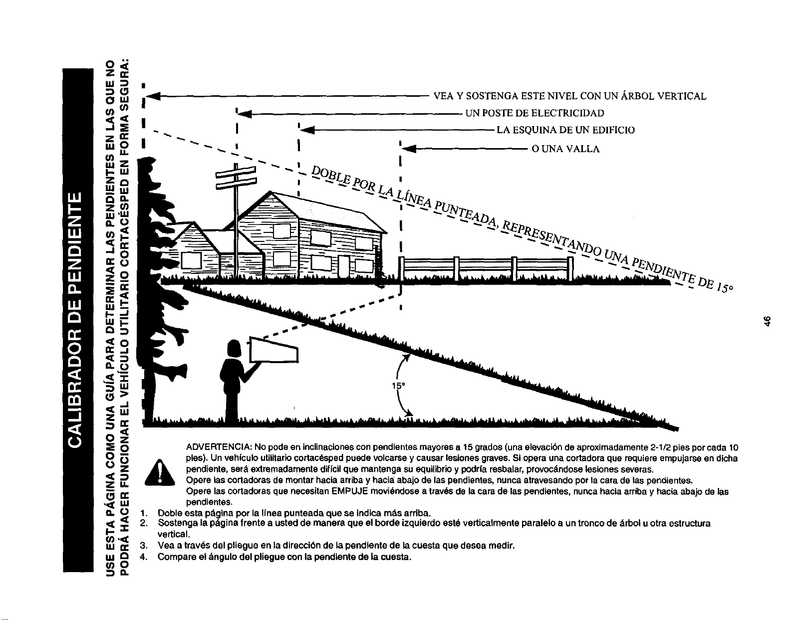
VEA Y SOSTENGA ESTE N1VEL CON UN _RBOL VERTICAL
UN POSTE DE ELECTRICIDAD
LA ESQUINA DE UrN EDIFICIO
0 UNA VALLA
-. DE lSo
ADVERTENCIA:Nopode en inclinacionesconpendientesmayoresa 15grades(una elevacibndeaproximadamente 2-1/2 piespercada10
pies).Unvehfculoutilitariocortac_spedpuedevolcarsey causarlesionesgraves.SI operauna cortadoraque requiereempujarseendicha
pendiente,ser&extremadamentediffcUque mantengasuequilibrio y podrfaresbalar,provoc_ndoselesionesseveras.
Opere lascortadorasde mentarhaclaarribay haciaabajodelaspendientes,nuncaatravesandoperla caradelaspendientes.
Opere lascortadorasque necesitanEMPUJE movi_ndosea trav_sde lacarade laspendientes,nuncahactaarribay haclaabajode las
,0=__ _ pendientes.
1. Doble esta pdginaper la Ifneapunteada que se indicamdsarriba.
2
• Sostengala p_ginafrente a ustedde manera que elborde izquierdoest_ verUcalmenteparaleloa untroncode _.rboluotra estructura
I._<Z vertical.
w n- 3. Vea a trav_sdel pliegue enla direccibnde la pendiente de lacuesta que desea medir.
_ _ 4. Compareel_ngulodelpliegueconlapendlentedelacuosta.
ID
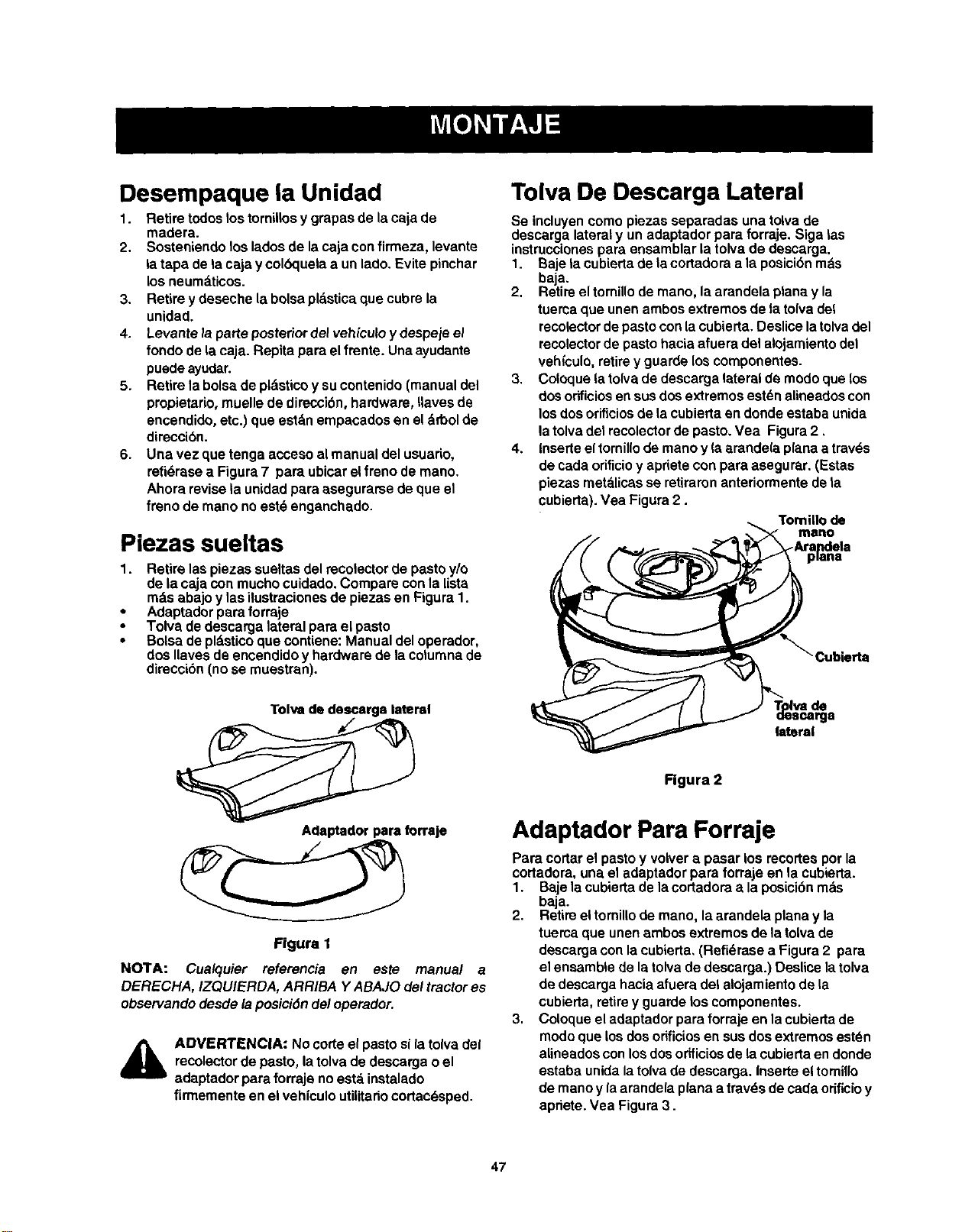
Desempaque la Unidad
1. Retire todos los tornillos y grapasde la caja de
madera.
2. Sosteniendo loslados de la caja confirmeza, levante
la tapa de la caja y colbquela a un lado. Evite pinchar
los neumdticos.
3. Retire ydeseche la bolsa pl_,sticaque cubre la
unidad.
4. Levantela parteposteriordelvehlculoy despejeel
fondo de tacaja. Repita para el frente. Unaayudante
puede ayudar.
5. Retire labolsa de pldstico y su contenido(manual del
propietario, muelle de direcoibn, hardware, Ilaves de
encendido, etc.) que estdn empacados en el drbol de
direcci6n.
6. Una vez que tenga acoeso almanualdel usuario,
refi_rasea Figura7 pare ubicarelfrenodemano.
Ahorarevisela unidadparaasegurarsede que el
frenode mano noest6 enganchado.
Piezas sueltas
1. Retire laspiezas sueltasdel recolector de pastoy/o
de la cajacon mucho cuidado. Compare con la lista
mds abajoy las ilustraeiones de piezas en Figura 1.
• Adaptador para forraje
• Tolva de descarga lateral para el pasto
• Bolsade pldstico quecontiene: Manual del operador,
dos Ilaves de encendido y hardware de la columna de
direcci6n (no se muestran).
Tolva De Descarga Lateral
Se incluyen como piezas separadas una tolva de
descarga lateral y un adaptador para forraje. Siga las
instrucciones para ensamblar la tolva de descarga.
1. Baje ta cubierta de la cortadora ala posici6n rods
baja,
2. Retire el tornillo de mano, la arandela plana y la
tuerca que unen ambos extremos de la tolva del
recolector de pasto con la cubierta. Deslice la tolva del
recolector de pasto hacia afuera del alojamiento del
veh(culo, retire y guarde los componentes.
3. Coloque la tolva de descarga lateral de modo que los
dos o_icios en sos dos extremos est_n alineados con
los dos orificios de ta cubierta en donde estaba unida
la tolva del recolector de pasto. Vea Figura 2,
4. Inserte el tornillo de mano y la erande(a plana atrav(_s
de cada orificioy apdete con para asegurar. (Estas
piezas met_.licas se retiraren anteriormente de ta
cubierta). Vea Figura 2.
Tomillo de
mano
Tolva de desosrga lateral
lateral
Figura 2
Adaptedorpara forraje
Figure 1
NOTA: Cualquier referencia en este manual a
DERECHA, IZQUIERDA, ARRIBA Y ABAJO del tractor es
observando desde la posici6n del operador.
A
ADVERTENCIA: Nocorteel pastosilatolva def
recolectordepasto, latolvade descargaoel
adaptador pareforraje noest,. instalado
firmementeen elvehfculoutilitariocortac6sped.
Adaptador Para Forraje
Para cortarel pastoy volvera pasar los recortespor la
cortadora,una el adaptadorpara forrajeen la cubierta.
1. Bajelacubiertade lacortadoraala posicibnmbs
baja.
2. Retireeltomillodemano, laarandela planay la
tuercaque unenambosextremosde latolvade
descargacon laeubierta, (Refi_rasea Figura2 pare
el ensambiede latolvadedescarga.) Deslice latolva
de descargahaciaafuera dei alojamientode la
cubierta,retirey guardelos eomponentes.
3. Coloqueeladaptadorparaforraje en lacubiertade
modoque losdosorificiosensusdosextremosest_n
alineadosconlosdosorificiosde lacubiertaendonde
estaba unidalatolvade descarga.Inserteeltomillo
de manoy la arandelaplanea trav6sde cadaorificioy
apriete.Vea Figura3.
47
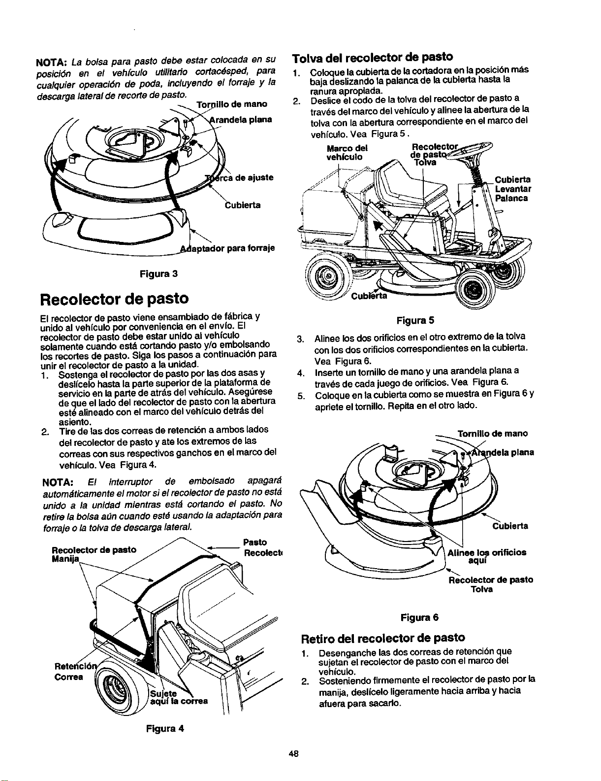
NOTA: La bolsa para pasto debe estar colocada en su
posici6n en el veh[culo utilitario cortac6sped, pare
cualquier operaci6n de pods, incluyendo el forraje y la
descargalateral derecorte depasto.
illo de mano
Cublerta
aptador pare forraje
Figure 3
Recolector de pasto
El recolectorde pasto viene ensambladode fdbrica y
unidoal vehIculoporconvenienciaen el envlo. El
recolectorde pasto debe ester unidoal vehfculo
solamentecuando estd cortandopastoy/o embolsando
los recortesde pasto. Slga los pasosa continuaclbnpara
unirel recolectorde pasto ala unidad.
1. Sostenga elrecolectorde pasto porlasdos asas y
deslicelohastala parte superiorde la plataformade
servicioen la parte deatrds del vehloulo.Asegt_rese
de que el ladodel recolectorde pastocon laabertura
est6 alineadocon el marcodel vehloulodetrdsdel
asiento.
2. Tire de lasdoscoffees de retencibna ambos lados
de/recolectorde pasto y ate losextremosde las
correasconsus respectivosganchos en el marcodel
vehfculo.Vea Figure4.
NOTA: El interruptor de embolsado apagard
autom_iticamenteel motorsiel recolector depasto no est_
unido ala unidad mientras estd cortando el pasto. No
retire labolsaa_n cuando estd usandola adaptacJ6npara
forrajeo/a tolva de descargalateral
Pasto
Recolector de pasto
Manija Recolect_
Tolva del recolector de pasto
1. Coloquelacubiertade lacortadoraen laposJci6r) mds
bajadeslizandola palancade lacubierta hastela
mnuraapropiada.
2. Desliceelcode de la tolvadel recolectorde pastoa
trav6sdel marcodel veh(culoyalinee laabertura de la
tolvacon laabertura correspondienteen el marcodel
vehiculo.Vea Figure5.
Marco del
vehfcuIo de
Cubierta
-Levantar
Palancs
Figure 5
3. Alinee los dosodficlosen elotto extremode la tolva
con losdos orificioscorrespondientesen lacubierta.
Vea Figure6.
4. Inserteun tomiilode manoy una arandela planaa
trav_sde cadajuego de odflolos.Vea Figure6.
5. Coloqueen lacubiertacomose muestra enFigura6 y
apriete eltomillo.Repita enel otrolado.
Tornlno de mano
Cubierta
Alines los odfloios
aquf
Recoleetor de pasto
Tolva
Correa
| coffee
Figure 4
Figure 6
Retiro del recolector de pasto
1. Desenganche lasdoscorreasde retencibnque
sujetanel recolectordepasto conel marco del
vehiculo.
2. Sosteniendofirmementeel recolectorde pastoporla
manija,desliceloligeramentehacia arribay hacia
afuera para sacado.
48
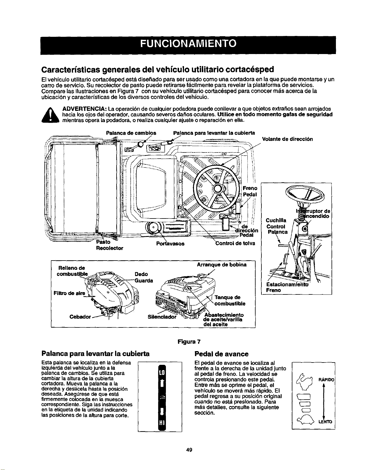
CaracteHsticas generales del vehfculo utilitario cortacdsped
Elvehfculo utilitariocortacdsped estd dise_ado para set usado como una cortadora en la que puede montarse y un
carro de servicio. Su recolector de pasto puede retirarse fdcilmente pare revelar la piataforma de servicios.
Compare las ilustraciones en Figura 7 con suvehiculo utilitariocortacdsped para conocer rods acerca de la
ubicacibn y caracterfsticas de los diversos controles del vehfculo.
4_lb ADVERTENCIA: La operacibnde cualquierpodadora puedeconllevara que objetosextraSossean arrojados
hacia losojosdel operador,causando severos da_os oculares.Utilice en todo momento gafas de seguridad
mientras opera la podadora,orealiza cualquier ajusteo reparacibnen ella.
Palanca de cambios
Palanca para levantar la cubierta
Volante de direccldn
Recolector
Relleno de
combustible Dedo
FIItro de air_
de tolva
Arranque de bobina
Tanque de
de aceite/varilla
del aceite
Cuchllla
Control
Freno
Palanca para levantar la cubierta
Estapalancase Iocalizaen ladefensa
izquierdadel vehl'culojuntoa la
palancade cambios.Se utilizapara
cambiarla alturade lacubierta
cortadora.Mueva lapalancaa la
derecha y desl|celahastalaposici6n
deseada.Asegniresedeque estd
flrmementecolocadaen iamuesca
correspondiente.Sigalasinstrucciones
enlaetiquetade la unidadindicando
lasposicionesde laalturaparacode.
Figure 7
Pedal de avance
El pedal de avance se Iocaliza al
frente a la derecha de la unidadjunto
al pedal defreno. La velocidadse
controlapresionandoeste pedal.
Entre mds se oprime el pedal, el
vehfculose moverb mds rbpido.El
pedal regresa a su posicibnoriginal
cuando no estdpresionado. Pera
rods detalies, consultela siguiente
secci(_n.
RiPIDC
LENTO
49
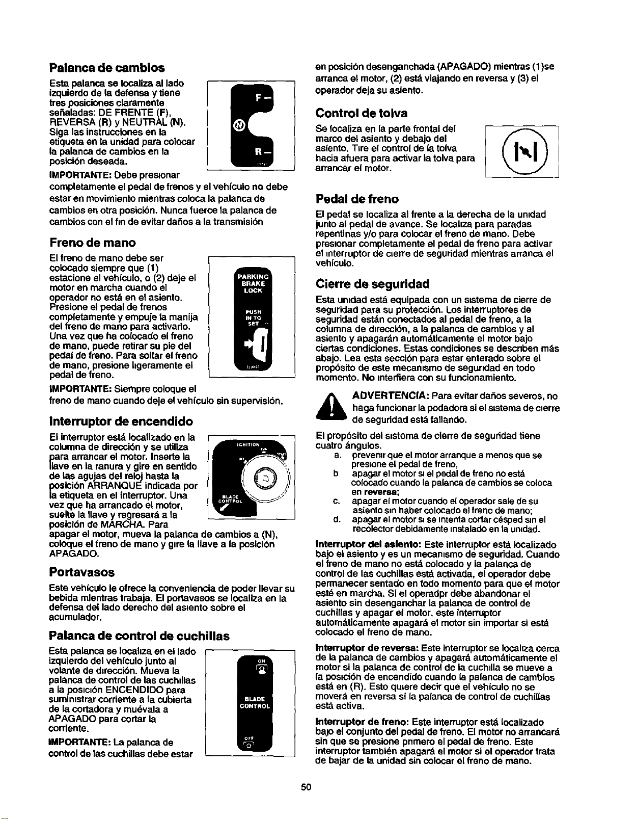
Palanca de cambios
Esta palancase Iocalizaal lado
izquierdode la defensa y tiene
tresposicionesclaramente
sei_aladas:DE FRENTE (F),
REVERSA (R) y NEUTRAL (N).
Siga lasinstruccionesen la
etiquetaen la unidadpara colocar
la palancade cambiosen la
posici6ndeseada.
IMPORTANTE:Debe preslonar
completamenteel pedal defrenosy el vehfculono debe
estar enmovimientomientrascoloca la palancade
cambiosenotra posicibn.Nuncafuerce la palancade
cambiosconel finde evitardaSosa la transmisibn
Freno de mano
El frenode mano debe ser
coiocadosiempreque (1)
estacioneel vehfculo,o (2) deje el
motoren marcha cuandoel
operador no estd en elasiento.
Presione el pedal de frenos
completamentey empuje la manija
del freno de mano para activado.
Una vez que ha co(ocadoelfreno
de mano, puede retirarsu piedel
pedal de freno. Para soltarel freno
de mano, presionellgeramentaei
pedal de freno,
IMPORTANTE: Siemprecoloqueel
frenode mano cuandodeje elvehlcuio sin supervisi6n.
Interruptor de encendido
Ei interruptorestd Iocalizadoen la
columnade direcci6ny se utiliza
para arrancar el motor. Insertela
Ilave en la ranura y gireen sentido
de tas agujasdel relojhasta la
posicibnARRANQUE indicadapor
la etiquetaen el interruptor.Una
vez que haarrancado el motor,
suelte la Havey regresard a la
posici6nde MARCHA. Para
apagar el motor, mueva la palanca de cambios a (N),
coloqueel freno de mano y glrela Havea la posicibn
APAGADO.
Po_avasos
Este veh|culole ofrece laconveniencia de poder Ilevarsu
bebida mientrastrabaja. El portavasosse Iocalizaen la
defensa del ladoderecho del as=entosobre el
acumulador.
Palanca de control de cuchillas
Esta palancase Iocalo.a en el lado
izquierdodel vehfculojuntoal
volante de d=reccibn.Mueva la
palanca de controlde lascuchdlas
a laposlclbnENCENDIDO para
sumimstrarcorrientea la cubierta
de lacortadora y mu6vala a
APAGADO para cortar la
corriente.
IMPORTANTE:La palancade
controlde lascuchillasdebe estar
en posicibndesenganchada (APAGADO) mientras(1)se
arranca el motor,(2) estdviajandoen reversa y (3) el
operadordeja suasiento.
Control de tolva
Se Iocalizaen la parte frontaldel
marcodel asientoy debajo del
asiento. Tire el controlde (atolva
haciaafuera para activar iatolva para
arrancar el motor.
Pedal de freno
El pedal se Iocalizaal frente a la derecha de la umdad
junto al pedal de avarice. Se Iocahzapara paradas
repentinasy/o para colocarel freno de mano. Debe
pres=onarcompletamente el pedalde frenopara activar
el mterruptorde clerrede seguddadmientrasarranca el
vehiculo.
Cierre de seguridad
Esta umdad est_ equipada con un slstemade cierrede
seguridadpara suprotecci6n. Losinterruptoresde
seguridad estdn conectadosal pedalde freno, a la
columna de direccibn,a la palanca de cambiosy al
asiento y apagardn automdticamenteel motorbajo
ciertas condiciones.Estas condiciones se descnben m&s
abajo. Lea esta seccibnpara estarenterado sobreel
propbsitode este mecanismo de segundaden todo
momento. No mterfieracon sufuncionamiento.
_bl AOVERTENCIA: Para evitardar3osseveros,no
haga funcionarlapodadorasielslstemadeclerre
de seguridad estbfallando.
El propbsito del s=stema de cierre de seguddad tiene
cuatro dngulos.
a. prevenlr que el motor arranque a menos que se
pres[one el pedal de freno,
b apagar el motor st el pedal de freno noestd
colocado cuando (a palanca de cambios se coloca
en reverse;
c. apagar el motor cuando e(operador sale de su
asiento s=nhaber colocado el freno de mano;
d, apagar el motor si se mtenta cortar c_sped sin el
recolector debidamente mstalado en la umded.
Interruptor del asiento: Este interruptor estd Iocalizado
bajo ei asientoyes un mecanismode seguddad.Cuando
el frenode mano no estdcolocadoy ia palanca de
controlde las cuchillasestdactivada, ei operadordebe
permanecer sentadoen todomomentopara que el motor
est_ en marcha. Si el operadprdebe abandonar el
asiento sin desenganchar lapalanca de control de
cuchillasy apagar el motor,este intarruptor
autom_tticamenteapagard el motorsin importarsi estd
colocadoel frenode mano.
Interruptor de reversa: Este interruptorse Iocahzacerca
de ia palanca de cambiosy apagard automdticamenteel
motorsila palanca de controlde iacuchdlase mueve a
la poaicidnde encendido cuando lapalanca de cambios
estd en (R). Estoqulere decirclueel vehiculono se
mover_ en reversa sila palancade control de cuchillas
estd activa.
Interruptor de treno: Este interruptor estd Iocalizado
baJo el conjunto del pedal de freno. El motor no arrancard
sin que se presione pnmero el pedal de freno. Este
interruptor tambidn apagard el motor si el operador trata
de bajar de la unidad sin colocar el freno de mano.
5O
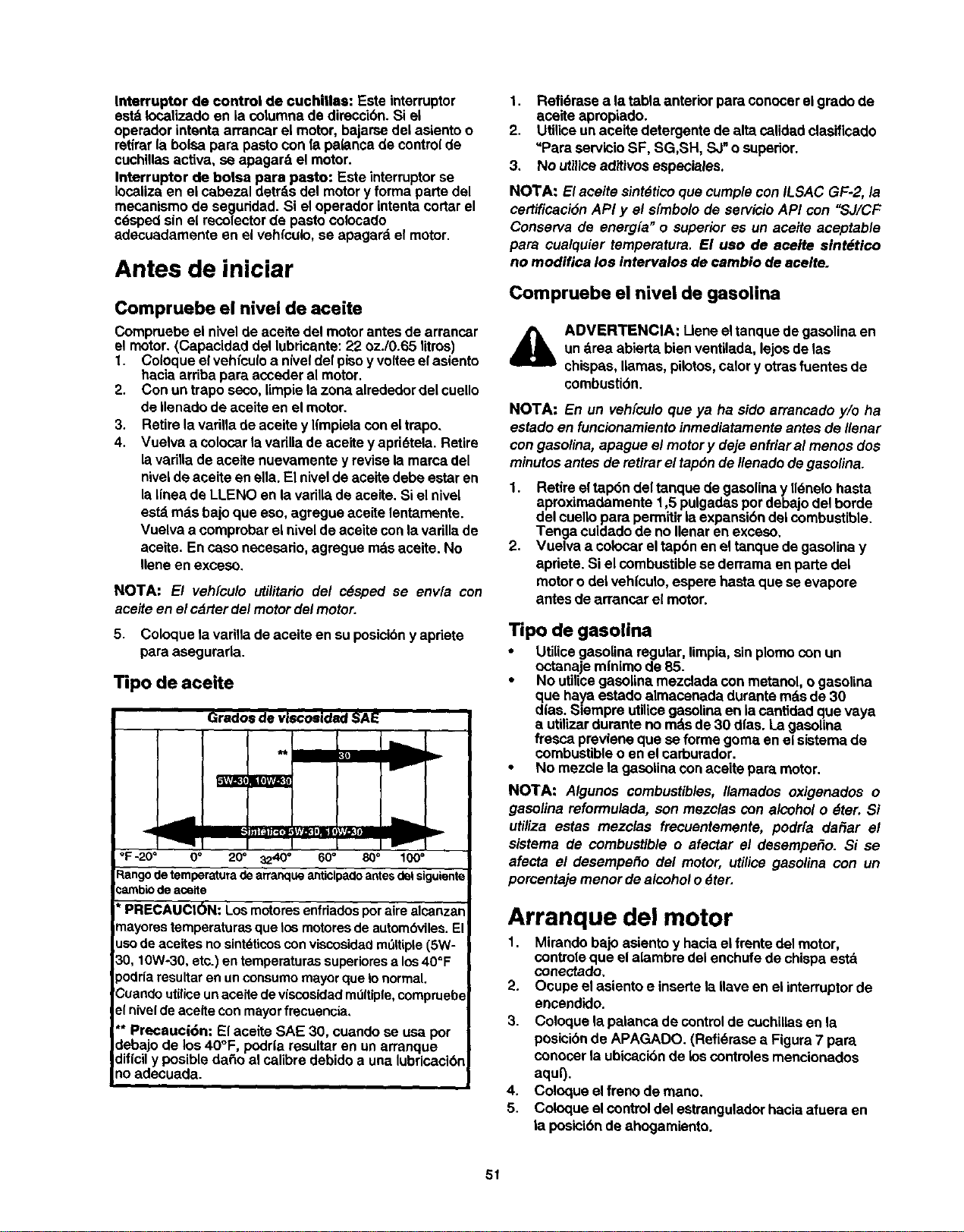
Interroptordecontroldecuchillas:Esteinterruptor
estdIocatizedoeniacotumnadedireccibn.Siei
operadorintentaarrencarelmotor,bajarsedelasientoo
retirarlabolsaparapastoconfapalancadecontrolde
cuchiUasactiva, se apagar6, el motor.
Interruptor de bolsa pare pasto: Este interruptorse
Iocaiizaen ei cabezal detrdsdel motory forma parte del
mecanismode seguddad. Si eloperedor intentacortarel
cdspedsin el recolectorde pastocolocado
adecuadamente en el vehfcuio,se apagard el motor.
Antes de iniciar
Compruebe el nivel de aceite
Compruebe ei nivelde aceite del motorantesde arrancar
el motor.(Capacidad del lubrioante:22 oz./0.65 litros)
1. Coioque elvehfcuioa n{veldel pisoy volteeelasiento
hacia arribapara accederal motor.
2. Con un trapo seco,limpiela zona alrededordel cuello
de ilenadode aceite en elmotor.
3. Retirela varillade aceite y I(mpielaconeltrepo.
4. Vuelva a colocarlavadliade aceitey apri6tela. Retire
lavarillade aceite nuevamentey revise lamarca del
niveldeaceite en ella.El nivelde aceRedebe estaren
laI[nea de LLENO en la varillade aceite.Si el nivel
estd rods bajoque eso, agregue aceite lentamente.
Vuelva a comprobarel nivelde aceitecon lavarillade
aceite. Encaso necesario, agregue mdsaceite. No
Ileneen exceso.
NOTA: El veh[culo utilitario del c_sped se env[a con
aceiteen el carter del motordel motor.
5. Coloque la vadllade aceiteen suposicibny apriete
para asegurarla.
Tipo de aceite
Grados de viscosidad SAE
I
°F-20 ° 0° 20= 3240 ° 60° 80= 100 °
:_angode temperatura de arranque artticipacloantes del siguiente
:ambio de aceite
' PRECAUCION: Los motores enfriados por aire alcanza_
"nayorestemperaturas que los motores de autombviles. El
uso de aceRes no sint_ticos con viscosidad mt_ltiple(5W-
30, 10Wo30, etc.) en temperaturas supedores a los40_F
)odria resultar en un consumo mayor que Io normal.
'Cuando uttliceunaceite de viscosidad md{tiple, comprueb(
e{nivel de aceite con mayor frecuencia,
** Precauci6n: El aceite SAE 30, cuando se usa por
debajo de los 40°F, podda resultar en un arranque
diflcil y posible da_o al calibre debido a una lubricacibn
no adecuada.
1. Refi_rase a la tabla anteriorpara conocerel grado de
aceite apropiado.
2. Utilioeun aceite detergente de altacalidadclasifioado
=PareservicioSF, SG,SH, SJ_o superior.
3, No utiliceaditivosespeciales.
NOTA: El aeeite sintdticoque cumplecon ILSAC GF-2, la
certfficacidnAPI y el sfmbolode servicioAPI con "SJ/CF
Conserva de energfa" o superior es un aceite aceptable
para cualquier temperatura. El uao de aeelte sintdtico
no modifica los intervalos de cambio de aceite.
Compruebe el nive| de gasoUna
ADVERTENClA: Lieneeltanquede gasolinaen
un drea abiertabienventilada,lejosdelas
chispas, llamas,piiotos,calory otrasfuentes de
combustidn.
NOTA: En un veh[cu/oque ya ha sidoarrancado y/o ha
estado en funcionamientoinmediatamenteantes de Ilenar
con gasolina, apague el motor y deje enfriaral menos dos
minutos antes de retirarel tapdnde I/enadode gasolina.
1. Retire eltap6n del tanquede gasolinay II_neio hasta
aproximadamente 1,5 pulgadaspordebajodel horde
del cuellopara permitirlaexpansibndelcombustible.
Tenga cuidedode no Ilenaren exceso,
2. Vuelva a colocarel tap6n en eltanque degasolinay
apriete. Si elcombustiblese derramaen parle del
motorodel vehioulo,espere hastaque se evapore
antesde arrancar e{motor.
•ripo de gasolina
• Utilicegasolinaregular,limpia,sinplomocon un
octanaje mfnimode B5.
• No utilioegasolinamezclada con metanol, ogasolina
que haya estado almacenadadurente rods de 30
dias. Siempre utilioegasolinaen iacantidad que vaya
a utilizardurante no mdsde 30 dfas. La gasolina
fressapreviene que se formegoma en el sistemade
combustible o enel carburador.
• No mezcle la gasolinaconaceite para motor.
NOTA: Algunos combustibles, Ilamados oxigenados o
gasolina reformulada, son mezclas con alcoholo _ter. Si
utiliza estas mezclas frecuentemente, podr[a da_ar el
sistema de combustible o afectar el desempe_o. Si se
afecta el desempe_o c/elmotor, utilice gasolina con un
porcentaje menor de alcoholo dter.
Arranque del motor
1. Mirando bajo asientoy haciael frentedel motor,
controle que el alambredel enchufedechispaestd
conectado,
2. Ocupe elasientoe insertela Ilaveen el interruptorde
encendido.
3. Coloque lapalanca de control de cuchiUasenla
posicibnde APAGADO. (Refi_rase a Figure7 pare
conocer la ubioack_nde loscontroles mencionados
aqurj.
4. Coloque elfreno de mano.
5. Coloque elcontroldel estranguladorhacia afuera en
la posicibnde ahogamiento.
51
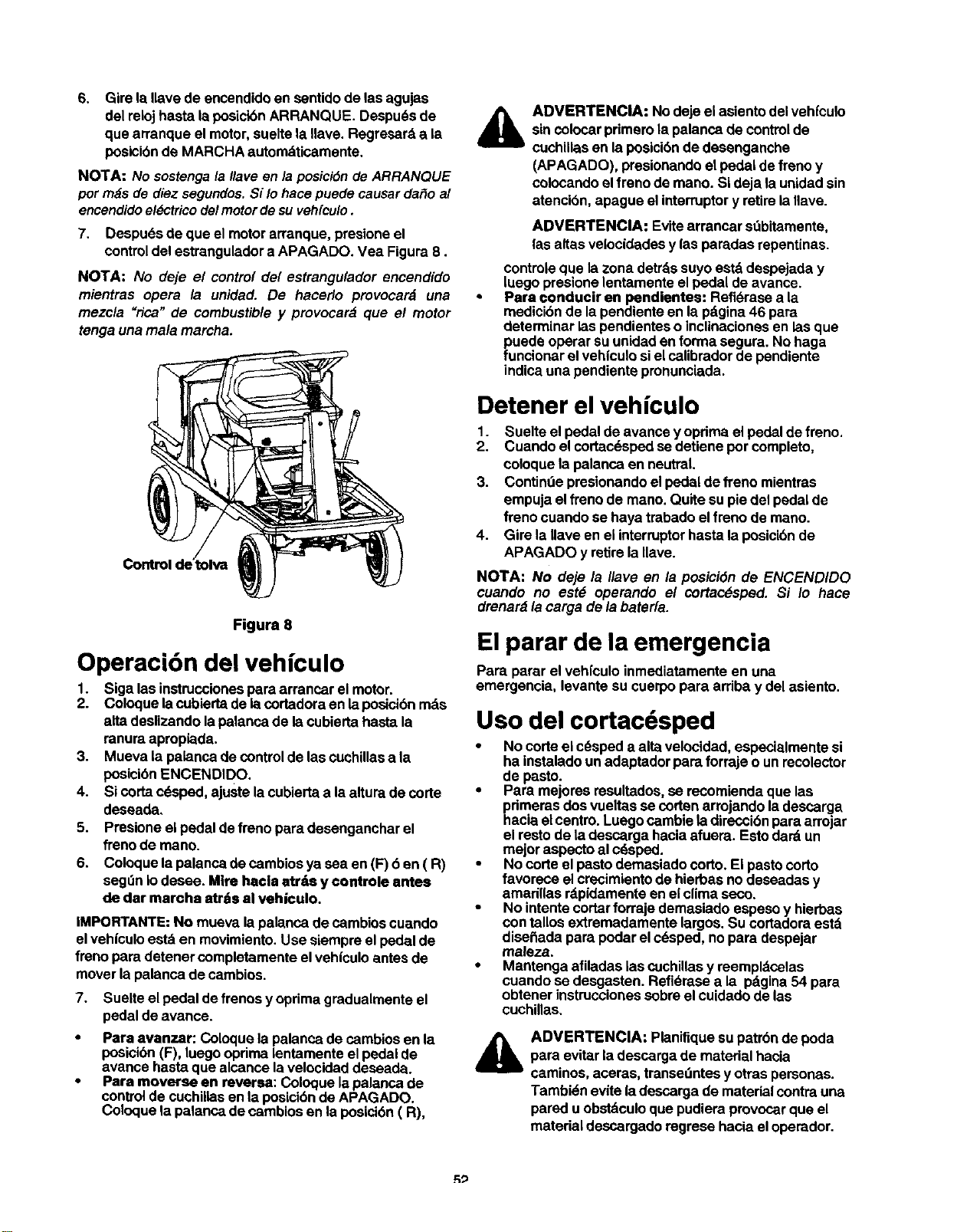
6. Gire la Ilave de encendidoen sentidode las agujas
del relojhasta laposicibnARRANQUE. Despu_sde
cluearranque elmotor,sueltela Ilave. Regresarda la
posicibnde MARCHA automdUcamente.
NOTA: No sostenga /a Ilave en la posicidn de ARRANQUE
por rods de diez segundos. Si /o hace puede causar da_o a/
encendido el_ctrico de/motor de su vehfcu/o .
7. Despudsde que el motorarranque, presioneel
controldel estranguladora APAGADO. Vea Figure 8.
NOTA: No deje el control de/estrangu/ador encendido
mientras opera la unidad. De hacerlo provocard una
mezcla "rica" de combustible y provocard que el motor
tenga una mala marcha.
Figura 8
Operaci6n del vehfculo
1. Siga las instruccionespara arrancar el motor.
2. Coloquelacubiertade iacodadoraen laposicibnmds
alta deslizandolapalancade la cubieda hasta la
ranuraapropiada.
3. Mueva lapalanca decontrolde lascuchillasa la
posicibnENCENDIDO.
4. Sicortacdsped, ajuste lacubiertaa laalturade corte
deseada,
5. Presione elpedalde frenopara desenganchar el
frenode mano.
6. Coloquelapalanca decambiosya sea en(F) 6 en(R)
seg0n io desee. Mire hacle atrds y controle antes
de dar marche atrite al vehiculo.
IMPORTANTE:No mueva lapalanca decambioscuando
el vehlculoest8 en movimiento.Use siempre el pedalde
freno para detenercompletamente elvehiculoantesde
mover lapalanca de cambios.
7. Suelte el pedalde frenosy oprimagradualmenteel
pedalde avarice.
• Para avanzar: Coloque lapalanca de cambiosen la
posicibn(F), luego oprimalentamenteel pedalde
avance hastaque alcance lavelooidaddeseeda.
• Para moverse en reversa: Coloque lapalancade
controlde cuchillasenla posici6nde APAGADO.
Coloque la palancade cambiosen la posicibn(R),
ADVERTENCIA: No deje el asientodel vehfculo
sincolocar primerolapalanca de control de
cuchillasen laposicidnde desenganche
(APAGADO), presionandoelpedal defreno y
colocandoelfreno de mano. Sideja la unidadsin
atencibn,apague el interruptory retirela Ilave.
ADVERTENCIA: Evitearrancar st_bitamente,
lasaltas velocidadesy lasparadas repentinas.
contrele que la zonadetrdssuyoestd despejada y
luegopresionelentamenteelpedal de avance.
Para conducir en pendientes: Refi_rase a la
medicibn de lapendienteen la pdgina46 para
determinar laspendienteso inclinacionesen laeque
puede operar suunidaden forma segura. No haga
funcionar elvehiculosiel calibradorde pendiente
indicauna pendienteprenunclada.
Detener el vehiculo
1. Suelte el pedalde avance y opdma elpedal defreno.
2. Cuando elcortacdspedse detiene porcompleto,
coloquela palanca en neutral.
3. Continde presionandoel pedaldefreno mientres
empujaelfreno de mano.Quite supie del pedalde
frenocuando se haya trabado elfreno de mano.
4. Gire la Ilave en eiinterruptorhastala posici6nde
APAGADO y retirela Ilave.
NOTA: No deje la //ave en la posici6n de ENCENDIDO
cuando no est# operando el cortac6sped. Si Io hace
drenardla carga de labater[e.
El parar de la emergencia
Pare pararel vehlculo inmediatamenteen una
emergencia, levante su cuerpopara arriba y del asiento.
Uso del cortacdsped
• No corteei cdspeda alia velocidad, especialmentesi
ha instaladoun adaptadorpare forraje o unrecolector
de pasto.
• Pare mejoresresultados,se recomiendaque las
pdmerasdos vueltasse corten arrojandoladescarga
hacia elcentro.Luegocambie ladireccibnparaarrojar
el restode la descargahacia afuera. Esto dardun
mejor aspectoal cdsped.
• No code el pastodemasiado corto. Eipasto corto
favorece elcrecimientode hierbas no deseadas y
amarillas rdpidamenteenel climaseco.
• No intentecortarforraje demasiado espeso y hierbas
con tallosextremadamente largos.Sucortadoraestd
dise_ada para podar elc6sped, no para despejar
maleza.
• Mantenga afUadas lascuchillasy reempldcolas
cuando se deegasten. Refldresea la pdgina54 para
obtener instruccionessobreelouidadode las
cuchillas,
ADVERTENClA: Planifiquesupatrbn de poda
para evitar ladescargade matedal hacia
caminos, aceras, transedntesy otras personas.
Tambidneviteladescarga de materialcontrauna
pared uobstdculoque pudieraprovocarque el
matedal descargadoregrese hacia eloperador.
R_
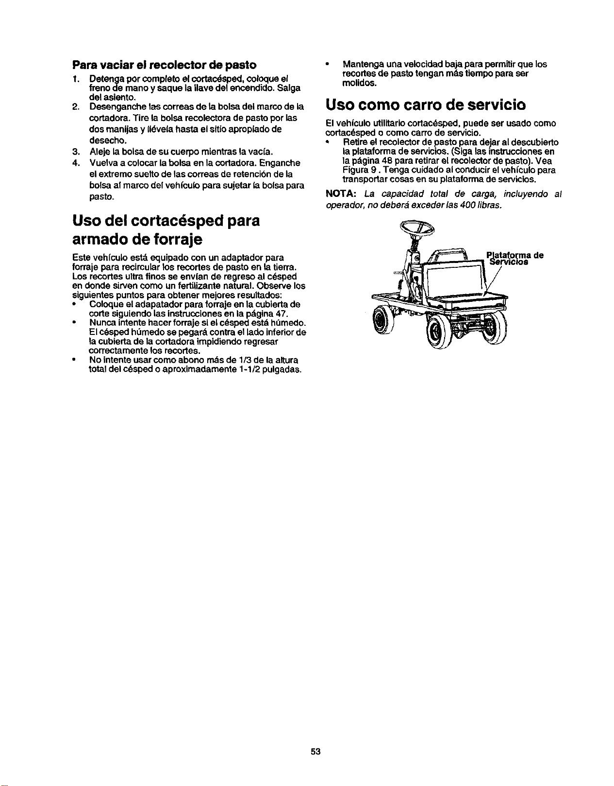
Para vaciar el recolector de pasto
I. Detenga porcompletoel cortac_sped,coloqueel
frenode manoy saque la,ave del encendido.Salga
del asiento.
2. Desenganche 1ascorreasde la bolsadel marcode la
cortadora.Tire la bolsarecolectorade pastaporlas
dos manijasy (16ve(ahasta el sitioapropiadode
desecho.
3. Aleje labolsade sucuerpo mientraslavacia.
4. Vuelva a colocarlabolsa en lacortadora. Fnganche
elextremo sueltode 1ascorreas de retencibnde la
bolsaalmarco del vehl"culopara sujetarla bolsapara
pasto.
Uso del cortacdsped para
armado de forraje
Este vehfculo estdequipado con un adaptador para
forraje para recircularlos recortesde pasta en la tierra.
Los recortesultrafinos se envl'ande regreso al c_sped
en donde sirvencomo un fertiUzante natural.Observe los
siguientespuntos para obtener mejoresresultados:
• Coloqueel adapatadorpara forrajeen la cubiertade
corte siguiendolasinstruccionesen la pdgina47.
• Nunca intentehacer forrajesiel cdspedestd h,',medo.
El ¢6sped hOmedose pegard contrael ladoinferiorde
la cubiertade lacortadoraimpidiendoregresar
correctamentalos recortes.
• No intentausar comoabono mdsde 1/3 de laaltura
totaldel cdspedo aproximadamente 1-1/2 pulgadas.
• Mantenga unavelocidadbaja para permitirque los
recortesde pastotengan rodstiempopara ser
molidos.
Uso como carro de servicio
El vehiculoutilitariocortac_sped,puede ser usadocomo
cortacdspedo como carrode servicio.
• Retireel recolectorde pastapara dejaral descubierto
laplataforma de servicios.(Siga las instruccionesen
la pdgina48 para retirarel recolectorde pasto).Vea
Figura9. Tenga cuidadoalconducirelvehiculopara
transportarcosaserrsuplataformade servicios.
NOTA: La capacidad total de carga, incluyendo al
operador,no deber_ exceder las400 libras.
PJataf.o_made
_:JerVIClO$
53
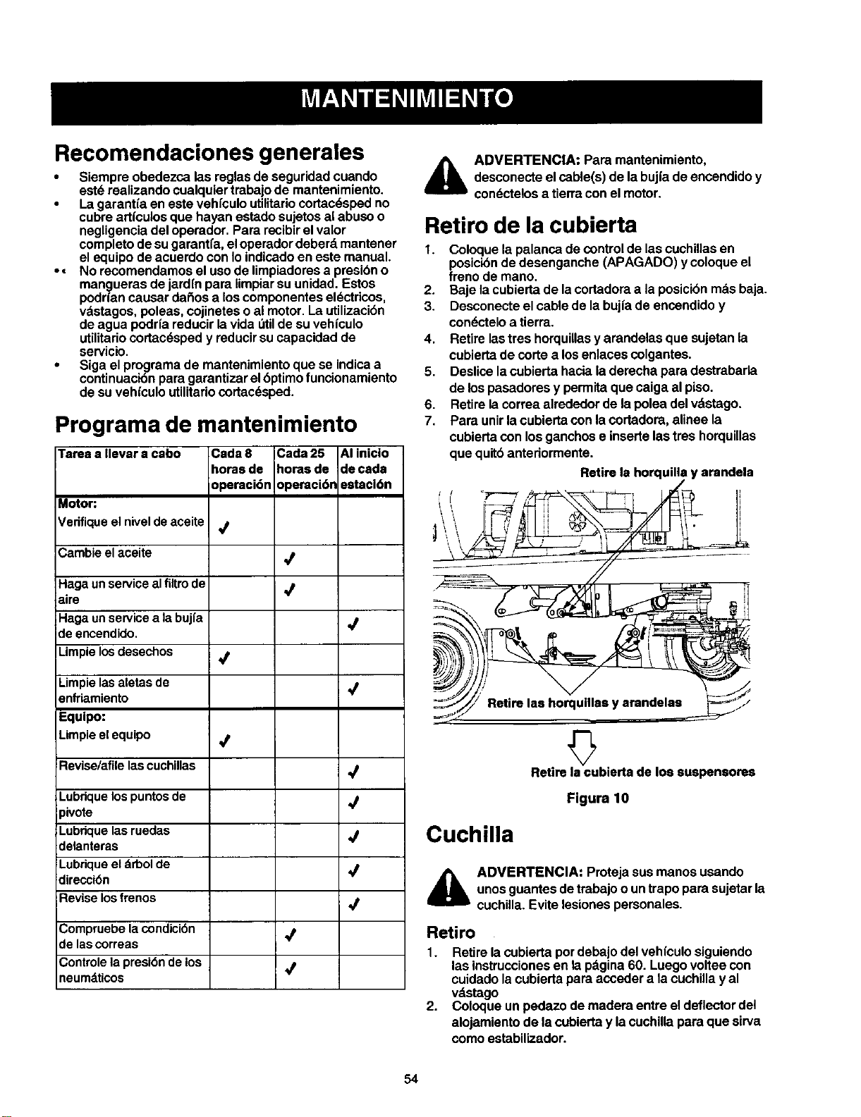
Recomendaciones generales
• Siempreobedezca las reglasdeseguridadcuando
est_ realizandocualquiertrabajode mantenimiento.
• Lagarantfa en este vehfculoutilitariocortac_sped no
cubreartfculosque hayan estadosujetosal abusoo
negligenciadel operador. Para recibirel valor
completodesugarantfa,eloperadordeberd mantener
el equipodeacuerdo con Ioindicadoen este manual.
•• No recomendamosel usode limpiadoresa presibno
mangueras dejardfn para limpiarsuunidad. Estos
podr|an causar da_os a los componentesel6ctricos,
vdstagos,poleas, cojineteso almotor.La utilizacibn
de agua podrfa reducirlavida t_tilde suvehfculo
utilitariocortac_spedy reducirsu capacidadde
servicio.
• Siga el programade mantenimientoque se indicaa
continuacibnpara garantizarelbptimofuncionamiento
de suvehloulouUlitariocortac_sped.
Programa de mantenimiento
Tarea a Ilevar a cabo Cada 8 Cada 25 AI inicio
horasde horasde decada
operaci6n opereci6n ostacidn
Motor:
Vedfique el nivel de aceite _f
Cambie el aceite
Haga un service al flltrode Vp
aire
Haga un service a la bujfa ,_
de encendido,
Limpie los desechos
Limpie las aletas de _t
enfriamiento
Equipo:
Limpie el equipo _t
Revise/afile las cuchillas
Lubdque los puntos de ,_/
_ivote
Lubdque las ruedas ./
delanteras
Lubdque el drbol de ,_
direccibn
Revise los frenos _t
Compruebe la condici(_n _t
de las correas
Controle la presi_n de los _f
neumdticos
,_ ADVERTENClA: Para mantenimiento,
desconecteelcable(s) dela bujfadeencendidoy
con_ctelosa tierraconel motor.
Retiro de la cubierta
1. Coloque la palanca decontrolde lascuchillasen
posicibndedesenganche (APAGADO) y coloqueel
freno de mano.
2. Baje la cubiertade lacortadoraa laposicibnmdsbaja.
3. Desconecteel cable de labujfade encendidoy
con_cteloa tierra.
4. Retirelastres horquillasy arandelasque sujetanla
cubiertade corte a losenlaces colgantes.
5. Deslicelacubierta haciala derechapara destrabada
de lospasadores y permitaque caiga al piso.
6. Retirela correa alrededorde lapolea delvdstago.
7. Para unirlacubiertacon lacortadora,alinee la
cubiertacon losganchose insertelas treshorquillas
que quitbanteriormente.
Retire lahor( y arandela
Cuchilla
Retire la cubierta de los suspensores
Figura 10
_lb ADVERTENCIA: Protejasusmanos usando
unosguantesdetrabajoo untrapopara sujetarla
cuchilla.Evitelesionespersonales.
Retiro
1. Retirelacubiertapordebajodel vehfculosiguiendo
lasinstruccionesen lap_.gina60. Luegovoltee con
cuidadolacubiertapara acceder a lacuchillay al
vdstago
2. Coloque unpedazo demadera entre eldeflectordel
alojamientode lacubiertay la cuchillapapaque sirva
comoestabJlizador.
54
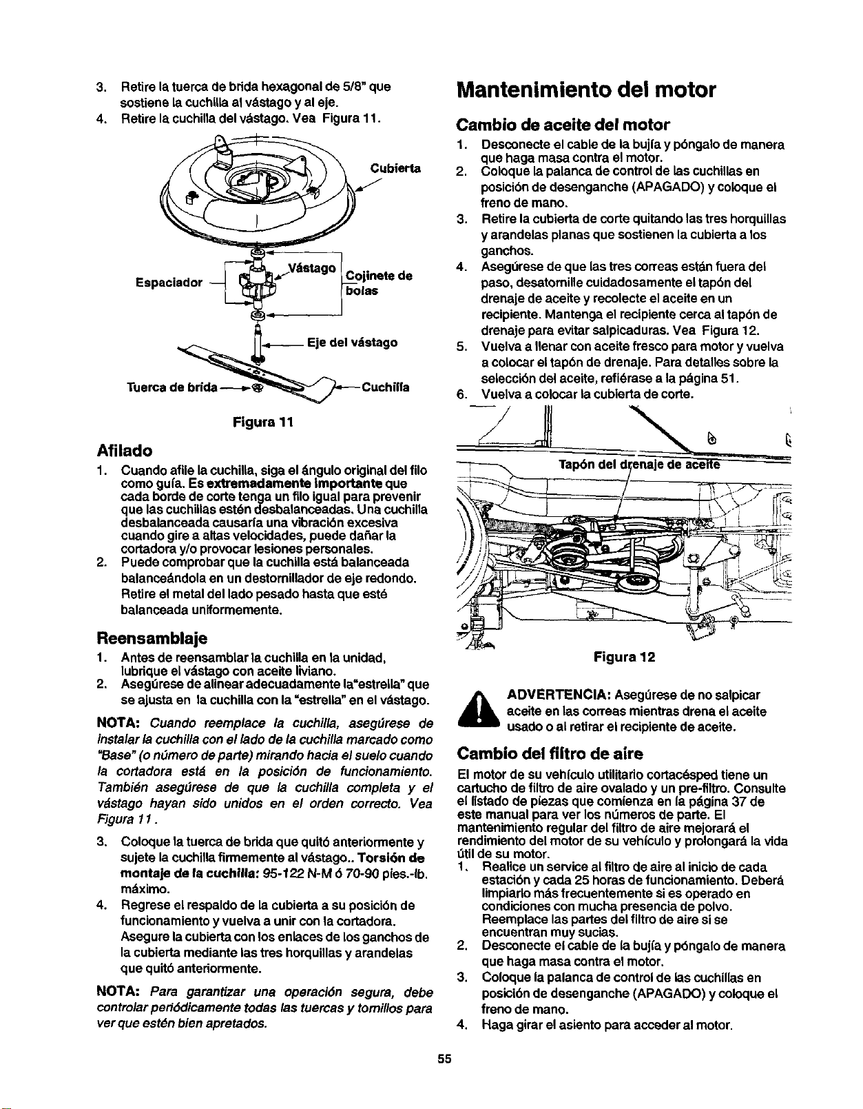
3. Retirelatuerca de bdda hexagonalde 5/8" que
sostienelacuchillaal vdstagoy aleje.
4. Retirela cuchinadelvdstago, Vea Figura11.
_ubierta
Espaciador _ _'_V_tstag° _c°jlnete de
F'°"
D"--'-'-- Eje del vatstago
_,_ CuchilfaTuerca de brida---,-_
Figura 11
Afilado
1. Cuando afile lacuchilla,siga eldngulooriginaldel filo
como gufa. Es extremadamente Importante que
cada borde de cortetenga un filoigualpara prevenir
que lascuchiilasestdndesbalanceadas, Una cuchilla
desbalanceada causar|a una vibracibnexcesiva
cuando girea altasvelocidades,puede da_ar la
cortadoray/o provocarlesionespersonales.
2. Puede comprobarque la cuchillaestd balanceada
balancedndolaen un destomilladorde eje redondo.
Retireel metal del ladopesado hasta que estd
balancoada uniformemente.
Mantenimiento del motor
Cambio de aceite del motor
I,
2.
3.
4.
Desconecte elcable de labujla y pbngalode manera
que haga masa contrael motor.
Coloque lapalanca decontrolde lascuchillasen
posicibnde desengancha (APAGADO) ycoloqueel
freno de mano.
Retirela cubiertadecorte quitandolastreshorquillas
y arandelas planasque sostienen lacubiertaa los
ganchos.
Asegdrese de que lastrescorreas estdnfuera del
paso, desatomillecuidadosamenteel tap6n del
drenaje de aceitey recolecteel aceiteen un
recipiente. Mantenga el recipientecercaal tapbnde
drenaje para evitarsalpicaduras.Vea Figura12.
Vuelva a Ilenar conaceite fresco para motory vuelva
a colocareltap6n de drenaje. Para detallessobrela
selecci6ndel aceite, refidrasea la pdgina51.
Vuelva a colocarla cubiertade code.
Reensamblaje
1. Antes de reensamblarlacuchillaen la unidad,
lubriqueel vdstagocon aceite liviano.
2, Aseg0rese deaUnearadecuadamente la=estrella"que
se ajusta en la cuchillacon la=estreUa"en el vdstago.
NOTA: Cuando reemplace la cuchilla, asegdrese de
instalarla cuchillacon el ladode la cuchillamarcado como
"Base"(o ndmero departe) mirandohacia elsuelocuando
la cortadora estd en la posici6n de funcionamiento.
Tambi6n aseg_rese de que la cuchilla completa y el
v_stago hayan sido unidos en e/ orden correcto. Vea
FJgura11.
3. Coloque latuercade bddaque quit6 anteriormente y
sujete lacuchillafirmementeal vdstago..Torsi6n de
montaje de la cuehilla: 95-122 N-M (_70-90 pies.-Ib.
mdximo.
4. Regrese el respaldode la cubiertaa su posicibnde
funcionamientoy vuelva a unircon lacortadora.
Asegure lacubiertacon losenlaces de losganchosde
la cubiertamediantelas treshorquillasy arandeias
que quit6antedormente.
NOTA: Para garantizar una operaci6n segura, debe
controlar peri6dicamente todas las tuercas y tomillos para
vet que estdn bien apretados.
Figura 12
,_ ADVERTENCIA: Aseg0resede no salpicar
acaite enlas correasmientrasdrena elaceite
usadooal retirarel racipientede aceite.
Cambio del filtro de aire
El motorde su veh(culoutilitariocortac6spedtiene un
cartucho de filtro de aira ovalado y un pre-tiltre.Coneulte
el listadode piezas que comienza en la pdgina37 de
este manual para ver los nOmerosde parte. El
mantenimiento regulardel fiitrade aire mejorardel
rendimientodel motorde su veh|culoy prolongardla vida
t]tilde su motor.
1, Realiee un servicealfiltrode aire al iniciode cada
estactbny cada 25 horasdefuncionamiento.Deberd.
limpiadomds frecuentemente sies operadoen
condicionescon mucha presenciade polvo.
Reemplace las partesdelfiltro de aire sise
encuentranmuy sucias.
2. Desconecteel cable de labujl'ay p6ngalode manera
que haga masa contrael motor.
3. Coloque lapalanca decontrolde las cuchillasen
posicibndedesenganche (APAGADO) y coloqueel
frenode mano.
4. Haga girarel asientopara acceder almotor.
55
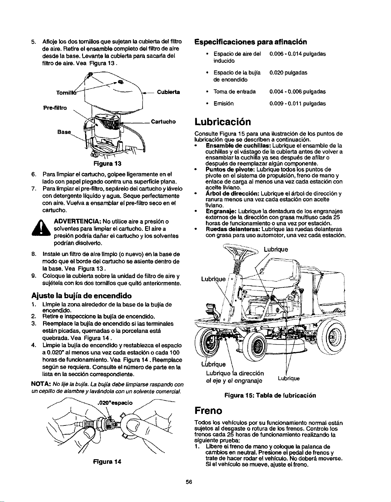
5.
Aflojelosdos tomillosque sujetanla cubiertadelfiltro
de alre. Retireel ensemble completodelfiltrode aire
desde labase. Levante la cubiertapare sacadadel
flltrode aire. Vea Figura t3.
Cubierta
Pre4iltro
Cartucho
Figure 13
6. Pare limpiarelcartucho,golpee ligeramenteenel
ladoconpapel plegadocontrauna superficieplana.
7. Para limpiarelpre-filtro,sepdreiodel cartuchoyIdvelo
condetergente h'quidoy agua. Seque perfectamente
con aim. Vuelva a ensamblar elpre-fi(trosecoenel
cartucho.
ADVERTENCIA: No utiliceaire a presibno
solventespare limpiarel cartucho.Elaire a
presibnpodrl'ada_ar eicartuchoy los solventes
poddandisolvedo.
8. Instale unfiltrode aim limplo(o nuevo)en la basede
modoque el hordedel cartuchose asiente dentrode
labase. Vea Figure13.
9. Coloque lacubiertasobre la unidadde filtrodeaire y
suj_telacon losdos tomillosque quitb antedormente.
Ajuste la bujfa de encendido
1. Limpiela zonaalrededor de la base de la bujia de
encendido.
2. Retiree inspeccionelabujfade encendido.
3. Reemplace labuj|a de encendidosi lasterminales
estdnpicadas, quemadas ola porcelanaestd
quebrada. Vea Figura 14.
4. Limpiela buj|a de encendidoy restablezcael espacio
a 0.020" ai menos una vez cada estacibnocada 100
horasde funcionamiento.Vea Figura 14. Reemplace
seg_n se requiem.Consulte el n_mem de parte en la
listaen laseccibncorrespondiente.
NOTA: No lije la buj[a. La buj{a debe limpiarse raspando con
un cepillo de alambre y lavdndola con un solvente comercial,
.020"espacio
Figure 14
Especificaciones para afinaci6n
Espacio de aire del
inducido
• Espacio de la buj|a
de encendido
• Toma de entrada
Emisibn
0.006 - 0.014 pulgadas
0.020 pulgades
0.004 - 0.006 pulgadas
0.009 - 0.011 pulgadas
Lubricacidn
Consulte Figura 15 para una ilostracibnde lospuntosde
lubricacibnque se describena continuacibn.
• Ensemble de cuchilles: Lubriqueelensemblede la
cuchillasy elvdstagode lacubiertaantesde volvera
ensarnblarlacuchillaya sea despudsde afilaro
despu_sde reemplazar alg_ncomponente.
• Puntos de pivote: Lubdquetodoslos puntosde
pivoteenel sistemade propulsibn,freno de manoy
enlace de carga al menos unavez cada estacibncon
aseite liviano.
• _,rbol de direcci6n: Lubrk:lueel drbol de direccibny
ranura menos una vez cadaestaci6n conaceite
liviano.
• Engranaje: Lubriquela dentadurade los engranajes
extemosde ladireccibncon grasa multiusocarla 25
horasde funclonamientoo unavez pot estacibn.
• Ruedas delanteras: Lubriquelas ruedasdelanteras
con grasapara usoautomotor, una vezcada estacibn.
Lubrique
Lubdque
el eje y el engranaje Lubrique
Figure 15: Table de lubricacidn
Freno
Todos los veh|culosper su funcionamientonormalest_n
sujetosal desgaste o rotura de los frenos. Controielos
frenoscada 25 horasde funcionamientorealizando la
siguienteprueba:
1. Libereelfreno de mano y coloquela palancade
camblosen neutral.Presioneei pedalde frenosy
tratede hacer rodarel vehfculo.No deberd moverse.
Si elveh{culose mueve, ajusteelfreno.
56
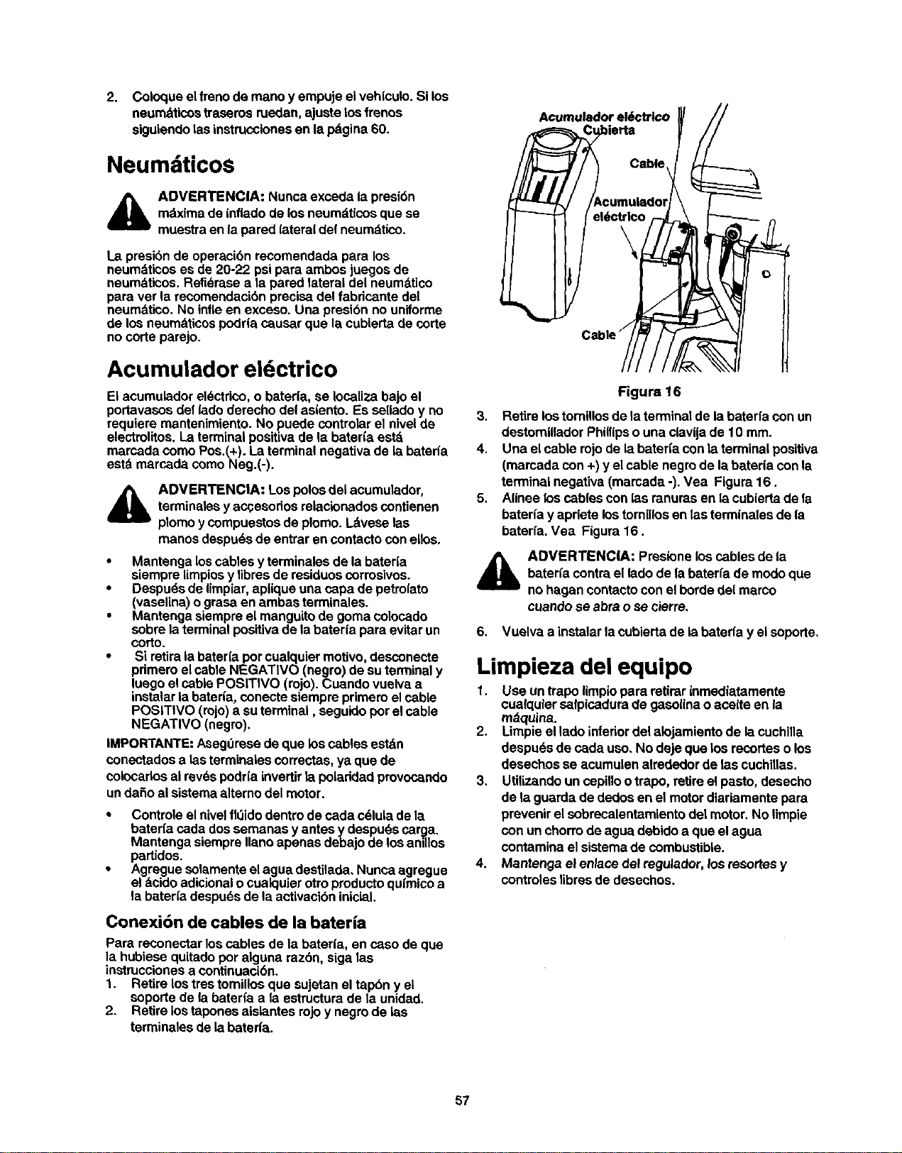
2. Coloque elfreno de mano yempuje el vehleulo.Si los
neumdticos traserosruedan,ajuste losfranos
siguiendolasinstruccionesen lapdgina 60.
Neumdticos
4_b ADVERTENCIA: Nuncaexceda lapresi6n
mdximade intiadode los neumdticosque se
muestraen lapared (ateraldel neumdtico.
La presibnde operacibn recomendadapara los
neumdticoses de 20-22 psi para ambos juegos de
neumdticos.Refidrase a la pared lateraldel neumdtico
para ver la recomendacibnprecisadel fabdcante del
neumdtico. No infleen exceso. Una presibn no uniforme
de los neumdticospodrlacaucar que la cublerta de corte
no corte parejo.
Acumulador eldctrico
El acumuledoreldctrico,o baterla, se Iocalizabajo el
portavasosdel (adoderecho del aslento. Es selladoy no
requiera mantenimiento. No puede controlarel nivelde
electrolitos.La terminalpositivade la bateria estd
marcada como Pos.(+). Laterminal negativade la baterfa
estd marcada como Neg.(-).
ADVERTENClA: Lospolosdel acumulador,
terminaleay accesodosrelaclenadoscontienen
plomoy compuestosde plomo. Ldveselas
manos despu6sdeentrar encontactoconelles.
• Mantenga loscables y terminalesde la bateda
siempre limpiosy libresde residuososrrosivos.
• De,spudsde limpiar,apliqueuna capa depetrolato
(vaselina)ograsa en ambas terminales.
• Mantenga slempreel manguito de goma colocado
sobre laterminalpositivade la bateda para evitarun
corto.
• Si retiraia bater(apor cualquiermotivo,desconecte
primeroel cable NEGATIVO (negro) desu terminaly
luego el cablePOSITWO (rojo).Cuando vuelva a
instalar labaterla, conecte siempm primeroel cable
POSITIVO (rojo)a suterminal, seguidoporelcable
NEGATIVO (negro).
IMPORTANTE:Aseg_rasede que los cables estdn
conectados alas terminalescorrectas,ya que de
colecados airevdspodr(a invertirla poladdad provocando
unda_o alsistemaalterno del motor.
• Controle elniveltiOidodentro decada cdluladela
baterfa cadados semanas y antesy despu6scar_.a.
Mantenga siemprallano apenas debajo de lee amllos
partidos.
• Agreguesolamenteelagua destilada,Nuncaagregue
el deido adicionalocualquierotropraductoqufmicoa
la bateriadespu(_sde la activacibninicial.
Conexi6n de cables de la bateria
Para reconectarlos cables de la baterla, en casode que
la hubiese quitadopot alguna razbn, siga las
instruccionesa continuacibn.
1. Retire los trestoraillosque sujetanel tap6n y el
soporte de la baterfa ale estructurade la unidad.
2. Retire lostaponesalelantes rojoy negrode las
terminales de labaterfa.
Acumulador el6ctrlco
Figura 16
3. Retirelos tomillosde la terminalde la baterfa con un
destorailladorPhillipso una ciavijade 10 mm.
4. Una elcable rojode la bateda con la terminalpositiva
(marcada con +)y elcable negrode labateria con la
terminal negativa(mamada -). Vea Figura 16.
5. AUneelos cables con las ranurasen la cubiertade la
baterfa y aprlete lostomiUosen las terminales de la
baterfa. Vea Figura16.
_lb DVERTENClA: Praslenelos cablesde la
bateda contrael ladode labaterfa de modoque
nohagan contactocon el bordedel marco
cuando se abra o se cierre,
6. Vuelva a instalarla cubiertade la baterfa y el soporte,
Limpieza del equipo
1. Use untrapo limplopara retirar inmediatamente
cuaiquiersalpicadurade gasolinao acoite en la
mdquina.
2. Limpieel ladoinferior del alojamiento de la cuchilla
despuds de cada uso.No deje que los recortesolos
desechosse acumulenalradedor delas cuchillas.
3, Utilizandoun cepilloo trap<),retireelpasto, desecho
de la guarda dededos enel motordiariamentepara
prevenirelsobracalentamientodel motor,No limpie
con un chorrodeagua debidoa que elagua
contaminael sistemade combustible.
4. Mantenga el enlace del regulador,/os resortesy
controleslibrasde desechos.
57
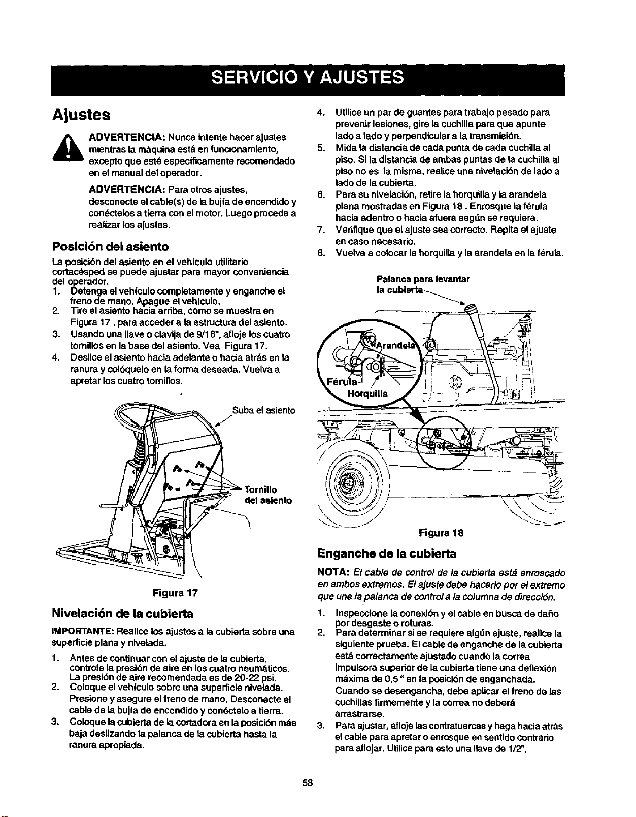
Ajustes
ADVERTENClA: Nunca intente hacer ajustes
mientras la mdquina estd en funcionamiento,
excepto que est_ especificamente recomendado
en el manual del operador.
ADVERTENCIA: Para otrosajustes,
desconecteelcable(s) de labujia de encendidoy
condctelosa tierracon elmotor. Luegoprocedaa
realizarlos ajustes.
Posicibn del asiento
La posicibndel asientoen el vehiculo utilitario
cortac6spedse puede ajustarpara mayor conveniencia
del operador.
1. Detenga el vehiculocompletamente y enganche el
frenode mano.Apague el vehiculo.
2. Tire elasientohacia arriba, comose muestra en
Figura17, para acceder a laestructuradel asiento.
3. Usando una Uaveoclavijade 9/16",afloje loscuatro
tomillosen labase del asiento.Vea Figura17.
4. Desliceelasiento hacia adelanteo hacia atrdsen la
ranuray col6queloen la formadeseada. Vuelva a
apratar loscuatrotornillos.
/Suba el asiento
Ire _" Tornillo
_el aslento
Figura 17
Nivelaci6n de la cubierta
IMPORTANTE:Realice los ajustesa lacubiertasobreuna
superficieplanay nivelada.
1. Antes de continuarcon elajuste de lacubierta,
controlela presi6nde aire en los cuatroneumdticos.
La presibnde aira recomendadaes de20-22 psi.
2. Coloque elvehiculo sobreunasuperficienivelada.
Presione yasegure elfreno de mano. Desconecteel
cablede labuj|a de encendidoy con_.-'teloa tierra.
3. Coloque lacubiertade lacortadora ell la posicibnrods
baja deslizandola palanca de lacubiertahasta la
ranura apropiada.
4. Utiliceun par de guantespara trabajopesado para
prevenirlesiones, gire lacuchillapara que apunte
ladoa 1adoy perpendiculara latransmisibn.
5. Mida la distanciade cadapuntade ceda cuchillaal
piso.Si ladistanciade ambas puntasde lacuchiUaal
pisono es la misma, realiceuna nivelacibndeladoa
ladode lacubierta.
6. Para su nivelaci6n,retirela horquillay laarandela
plana mostradasen Figura18. Enrosquelafdrula
hacia adentro ohacia afuera segdnse requiera.
7. Vedfique que elajuste sea correcto.Repitael ajuste
encaso neeesaric.
8. Vuelva a colocar lahorquillay la arandela en laf_rula.
Palanca para levantar
la cubi_'_ _
\
Figura 18
Enganche de la cubierta
NOTA: El cable de controlde la cubierta estd enroscado
en ambos extrernos.Elajustedebe hacerlopor el extremo
que unelapalanca de control a la colurnnade direcci6n.
1. Inspeccione la conexibny elcable en busca dedafio
pordesgaste oroturas.
2. Para determinar sise requierealgtlnajuste, realiee la
siguienteprueba. Elcable de enganche de lacubierta
estdcorrectamente ajustedocuando lacorrea
impulsorasuperiorde lacubiertatiene una deflexibn
mdximade 0,5 =en la posicibndeenganchada.
Cuandose desengancha, debe aplicarel freno de las
cuchillasfirmemente y lacorreano deberd
arrastrarse.
3. Para ajustar,aflojelascontratuemasy haga haciaatrds
elcable para apretaroenrosqueensentidocontrario
para aflojar.Utilicepara estouna navede 1/2_.
58
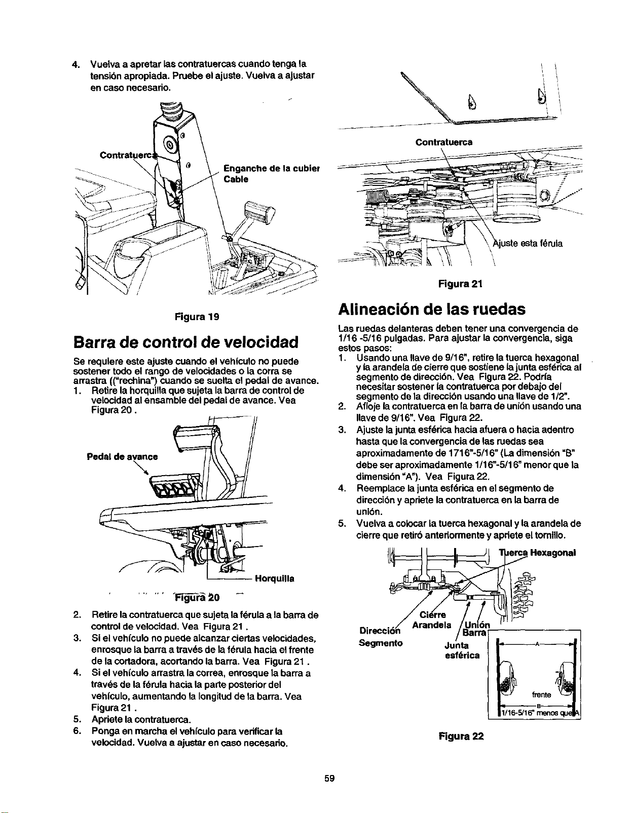
4. Vuelva a apretar las contratuercas cuando tenga la
tensi6n apropiada. Pruebe el ajuste. Vuelva a ajustar
en caso necesado.
Enganche de la cubier
Cable
/
/
!
/
Figura 19
Barra de control de velocidad
Se requiere este ajuste cuando el vehtculono puede
sostenertodoel rangode velocidadeso lacorra se
arrastra ((=rechina")cuandose suelta el pedal de avance.
1. Retire la horquillaque sujeta labarra decontrolde
velocidadal ensamble delpedal de avance. Vea
Figura20.
Pedal de avance
Horquilla
....... ,gFi r --
2. Retirelacontratuercaque sujetalaf_rulaa labarrade
controldevelocidad. Vea Figura21.
3. Si el vehiculono puedealcanzar ciertasvelocidades,
enrosquelabarra a trav6sde laf_rula hacia el frente
de la cortadora,acortandolabarra. Vea Figura21.
4. Si elvehfculo arrastralacorrea, enrosquela barraa
travds de lat_rula hacia laparte posteriordel
vehfculo,aumentando la Iongitudde labarra. Vea
Figure21.
5. Apdete lacontratuerca.
6. Ponga en marcha el veh[culopara vedficarla
velocidad.Vuelva a ajustaren casonecesado.
Contratuerca
Figura 21
Alineacibn de las ruedas
Laaruedas delanteras deben tener una convergencia de
1/16 -5/16 pulgadas. Para ajustar laconvergencia,siga
estospasos:
1. Usando una ,ave de 9/16", retirela tuerca hexagonal
y laarandela decierreque sostienelajuntaesf6dcaal
segmentode direcci6n.Vea Figura22. Podria
necesitarsostener(acontratuercapordebajodel
segmentode ladireccibnusandouna Ilave de 1/2".
2. Afloje lacontratuercaen labarrade uni6nusandouna
,ave de 9/16". Vea Figura22.
3. Ajustela juntaesf6dca hacia afuera o haciaadentro
hastaque laconvergenciade lasruedassea
aproximadamentede 1716"-5/16" (Ladimensibn_B"
debe set aproximadamente 1/16"-5/16"menorque la
dimensi6n"A").Vea Figura22.
4. Reemplace lajuntaesf6rica enel segmentode
direcci6ny aprietelacontratuercaenla barrade
unibn.
5. Vuelva a colocarla tuercahexagonaly la arandela de
cierreque retirbantedormentey aprieteel tomillo.
a Hexagonal
DireccWn ..... //Ba'r_'"
Segmento Junta
esfe_rica
1116-5/16"_ ¢
Figura 22
59
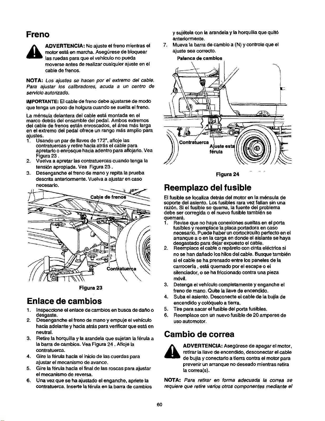
Freno
ADVERTENCIA: No ajuste elfreno mientrasel
motorestden marcha.AsegL_resede bloquear
lasruedaspara que elvehiculono pueda
moverse antes de realizarcualquier ajusteen el
cablede frenos.
NOTA: Los ajustes se hacen per el extremo del cable.
Para ajustar los calibradores, acuda a un centro de
servicioautorizado.
IMPORTANTE:Elcable de frenodebe ajustarse de modo
que tenga un pocode holguracuando se suelta elfreno.
La m_nsuladelantera del cable estd montada en el
marco detrdsdel ensamble del pedal. Ambosextremos
del cable de frenos estdn enroscados,el drea rods larga
en el extremo del pedal ofrece un rango rodsampliopara
ajustes.
1. Usando un par de Ilavesde 172", afloje las
contratuercasy retirehaciaatrds el cable pars
apretado oenrosquehaciaadentropara aflojado.Vea
Figura23.
2. Vuelva a apretar lascontratuercascuando tenga la
tensibnapropiada.Vea Figura23.
3. Desenganche el(Tenode manoy repita laprueba
descritaanteriormente.Vuelva a ajustarencaso
necesario.
Figura 23
Enlace de cambios
1. Inspeccioneel enlace decambiosenbusca deda_o o
desgaste.
2. Desenganche elfreno de mano y empuje elvehfculo
hacia adelantey hacia atrdspara veriflcarque estden
neutral.
3. Retirela horquillay la arandela que sujetanlaf_rula a
la barrade cambios. Vea Figura 24. Afloje la
contratuerca.
4. Gire laf(_rulahacia eliniciode lascuerdaspara
ajustarel mecanismode avance,
5. Gire laf6rula hacia elfinal de las roscaspara ajustar
el mecanismo de reversa.
6. Unavez que se ha ajustadoelenganche, apdete la
contratuerca,Insertela fdrula en la barrade cambios
7,
y suj_tela conla arandelay lahorquiliaque quitb
antedormente.
Mueva la barrade cambioa (N) y controleque el
ajuste sea correcto.
Palanca de cambios
Contratuerca
A
f6rula
Figura 24
Reemplazo del fusible
El fusiblese Iocalizadetrdsdel motoren la m(_nsulade
soportedel asiento. Losfusiblesrara vez falian sin una
raz6n. Si el fusiblese quema, lafuente del preblema
debe ser corregidao el nuevofusibletambk_nse
quemard.
1. Reviseque no hayaconexionessueltasen el porta
fusiblesy reemplace laplaca portadoraen caso
necesario.Puede haberuncortocircuitoperfectoen ei
arranquea oen la carga endonde elaisiantese haya
desgastadopara dejarexpuestoel cable.
2. Reemplace elcable o repdrelocon cintaeldctdcasi
no se han dahado loshilosdel cable. Busquetambi(_n
sielcable se ha prensadoentre los panelesde la
carrocer|a, estdquemado porel escape o el
silenciador,o se ha fdcoionado contrauna pieza
mbvil.
3. Detengael vehl'culocompletamentey enganche el
frano de mano. Quite laIlave deencendido.
4. Suba elasiento. Desconecteel cable de la bujfade
encendidoy colbqueloa tierra.
5. Tire para sacar elfusible del portafusibles.
6. Reemplace con un nuevofusible de20 amperes de
uso automotor.
Cambio de correa
ADVERTENCIA: AsegOresede apagar el motor,
retirar lanave de encendido,desconectarel cable
de bujia y conectarloa tierracontrael motorpara
prevenirun arranquenodeseado mientrasretira
la correa(s).
NOTA: Para retirar en forma adecuada la correa se
requiereque retire variosotroscomponentes mediante el
6O
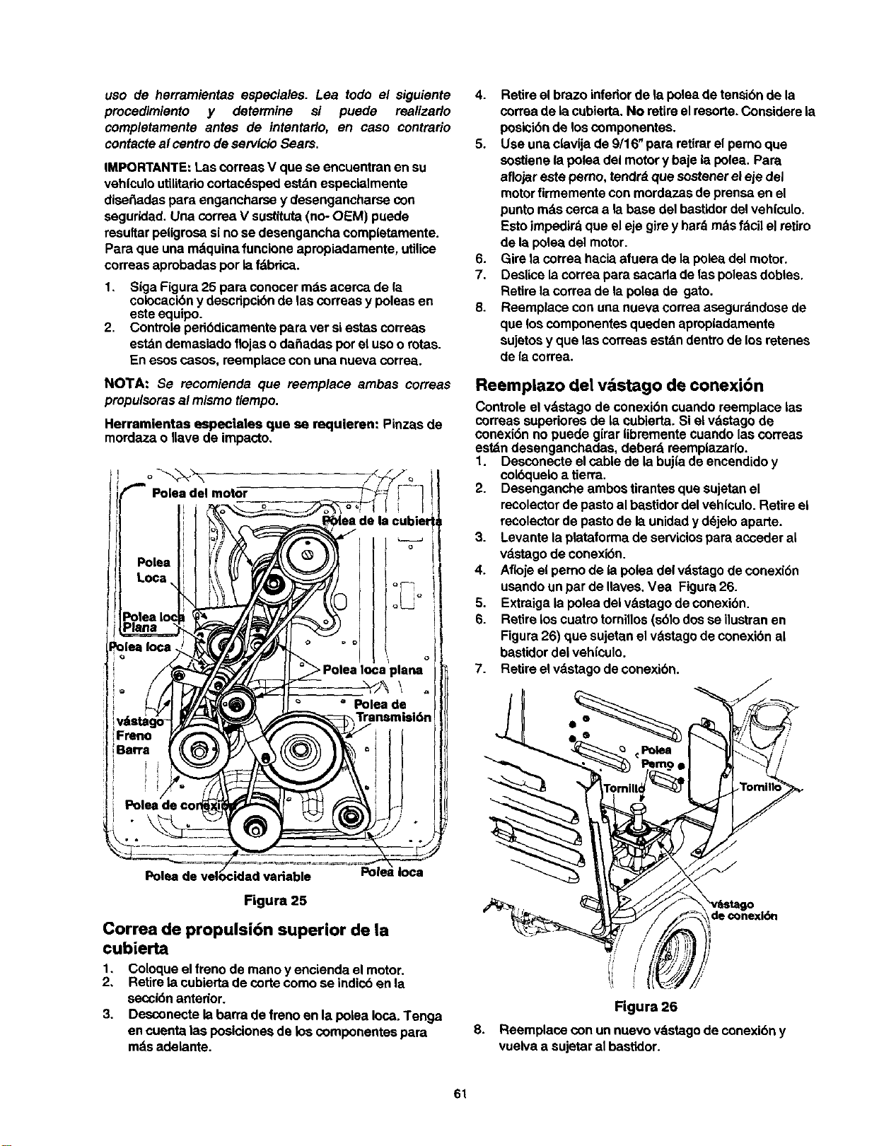
uso de herramientas especiales. Lea todo el siguiente
procedimiento y determine si puede realizarlo
completamente antes de intentarlo, en caso contrario
contacteat centrode servicioSears.
IMPORTANTE:Las correaeV que se encuentranen su
veh|culoutllitariocortacdspedestdn especialmente
dise_adas pare engancharse y desengancharse con
seguridad.Una correa V sustituta(no- OEM) puede
resultar peligrosasi nose desengancha compietamente.
Para que una mdquinafuncioneapropiadamente, utilioe
correas aprobadasper iafdbrica.
1. Siga Figure25 pare conocer mdsacerca de la
colocacibny descdpcibnde lascorreas y poleasen
este equipo.
2. Controle pedbdicamentepara ver si estascorreas
estdn demasiadoflojaso daSadas pot el usoo rotas.
En esoscasos, reemplace con una nueva correa.
NO'I'A: Se recomienda que reemplace ambas correas
propulsorasalmismo tiempo.
Herremientas especiales que se requieren: Pinzas de
mordaza o Ilave de impacto,
b
F Poleadel motor
Pole=
Loca
Polea k
Plane
_oiea Ioca
iFreno
iBan'a
biel
plane
L
Polea de velocidad variable Polea Ioca
Figura 25
Correa de propulsi6n superior de |a
cubierta
1, Coloque elfreno de mano y encienda el motor.
2, Retiretacubierta de code come se indicben la
secci6nanterior.
3, Desconectela barrade frenoen la polea loca. Tenga
eneuenta las posicionesde los componentes para
mdsadelante.
4. Retireel brazo infedorde la poleade tensibnde la
correade lacubierta.No retireelresorte.Considerela
posicibnde loscomponentes.
5. Use unaclavija de9/16" para retirarel pemo que
sostienela pofeadel motory baje la pofea.Para
aflojareste perno,tendrdque sostenerel eje del
motorfirmementecon mordazasde prensaen el
punto rodscerca ala base del bastidordel veh|culo.
Estoimpedirdque eleje girey hardmdsfdcil el retJro
de la poleadel motor.
6. Gire la correahacia afuera de lapolea del motor.
7. Deslicela correapara sacada de laspoleasdobtes.
Retirelacorrea de la poleade gato.
8. Reemplace con una nueva correaasegurdndose de
que los componentesqueden apropiadamente
sujetosy que lascorreasest_n dentrode losretenes
de lacorrea.
Reemplazo del vdstago de conexi6n
Controleel v_tstagode conexibncuando reemplace las
correassuperioresde la cubierta. Si elvdstagode
conexi6n no puede girar iibrementecuando las correas
estdn desenganchadas, deberd reemplazarlo.
1. Desconecte elcable de la buj|ade encendidoy
colbqueloa tierra.
2. Desenganche ambostirantesque sujetanel
recolectorde pastoal bastidordel veh|culo. Retireel
recolectorde pastode la unidady ddjeloaparte.
3. Levante laplataforma de serviciospare acceder al
vdstagode conexi6n.
4. Afloje elpemo de lapolea del vdstagode conexi6n
usandounpar de llaves.Vea Figura26.
5. Extraigaia poleadei vdstagodeconexi6n.
6. Retirelos cuatrotominos(s61odos se ilustranen
Figura26) que sujetanelvdstagodeconexibnal
bastidordel vehiculo.
7. Retireelvdstagode conexi6n.
Polea
/
/
/
8,
Figura 26
Reemplace con un nuevovdstagode conexi6ny
vuelva a sujetaral bastidor.
61

9. Trabajandopordebajodelvehiculo,vuelvaainstalar
lapoleadelvdstagodeconexibnconelpemoque
retirbantedormente,
10.Levantelaplataformadeserviciosderegresoensu
posicibndeoperacibn,vuelvaaunitelrecolectorde
pastossiserequiereyvuelvaa conectarelcable de la
bujlade encendido.
Correa propulsora
IMPORTANTE:Cuando una oambas correaspropulsoras
estdndesgastadas, reemplace ambascorreas. Si
reemplaza solamenteuna de elias afectard eldesempeho
desu vehfculoutilitariocortacdsped.
NOTA: Serd necesatio ajustar el enlace de control de
velocidad despu_s de/ reemplazo de ambas correas
propulsoras.
1. Retirelacubierta de corte.
2. Retirepdmero lacorreasuperiortrabajandoporla
parte de atrdsde la unidad.
3. Gire lacorrea para sacada de la polea Iocay luego
fuera de la poleade transmisi6ny lapoleade
velocidadvariable.
4. Trabajandodesde unlado de launidad, tirela polea
detensibnde lacorrea inferiorhacia laderechay
girela para sacada de esta polea.
5. Use una clavijade 9/16" para retirarel pernoque
sostienela polea del motory baje la polea. Para
aflojareste pemo, tendrd que sostenereleje del
motorfirmemente con lasmordazas de prensaenel
puntomdscama a labase del bastidordel vehfculo.
Estoimpedirdque eleje girey hard mdsfdcil el retiro
de la poleadel motor.
6. RetirelacorreadelasdospoleasIocas.Retirelacorreade
7,
8.
la polea de velocidad variabley lapolea de transmisi6n.
Reemplaca las correas superiores de la cubierta
siguiendo las instrucciones anteriores.
Reemplace la correa de propulsibn. Cuando vuelva a
instalar la correa, asegt_rese de que las correas
quedan en la parte interior de los tres retenes de la
las correas. Vea Figura 27.
NOTA: Mientras vuelvea unirelbrazo inferiorde lapolea
de tensi6n de/a correa de la cubierta,asegdrese de que
no se caiga e/resorte. Para comprobarque elresorteestd
co/ocadocorrectamente,saque haciaarriba la plataforma
de serviciosy deber_ poder vet un extreme de/ resorte
enganchadoa/orfficiorods grande sobrelap/ataforma.
:orrea
Re_t6nde
Correa
Ret_n
Figura 27
Si la mdquinanova a funcionardurante un periodo
mayor de 30 dl'as,prepdrela para su almacenamiento
como sigue.
Prepardndose para el
alrnacenaje
Acumulador el6ctrico
1. Cargue completamente la bateria. Labateda pierde
algo de sucarga cada dfa adn cuando launidadno
estden uso.NUNCA almacene labateda sin antes
habeda cargado completamente. Recargue la baterla
antesde regresarla alservieioocada dosmeses, Io
queocurra primero.
NOTA: Si un cargador con salida de 6 amperios no estd
disponible, un cargador rods bajo de la salida se puede
utilizarpara una duracidn mds larga. No cargue la bater[a
en una tarifa rods arriba de 6 amperios cornopuede dar_ar
la bater(a.
2. Cuando almacene launidadporperiodos
prolongados,desconecte loscables de la batert'ay
retire labaterl'a de launidad.
3. Guarde lasterminales y latapa de labateda limpiay
libdrelosde la corrosibn.Limpielabaterla con
bicarbonatode sosa o unproductode Iimpiezade
discoscomercialde labaterla.
IMPORTANTE:Importante: no permitaque ninguna
solucibnde la Iimpiezaconsigadentredela baterla.
Motor
1.
Para prevenirque se forme goma enel sistemade
combustibleo en laspartesdel carburador, sigael
paso apropiadodeentre losque se enumeran a
continuacibn:
a. Si el tanque de combustible contiene
gasolina oxigenada o reformulada (gasolina
mezclada con alcohol o 6ter), haga funcionar
el motorhasta que se agote la gasolina.
62
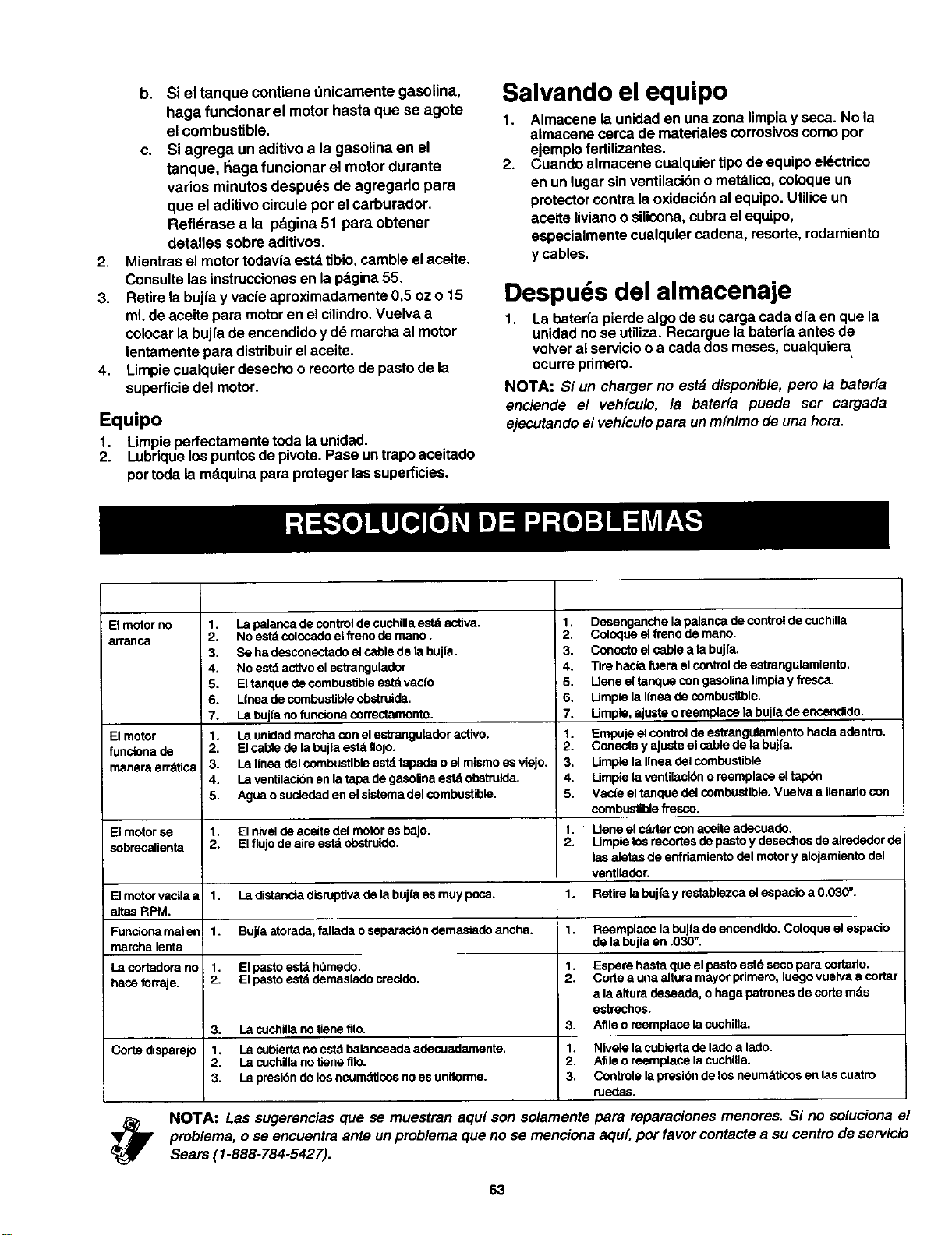
2,
3.
4,
b. Si el tanque contiene t_nicamentegasolina,
haga funcionar el motor hasta que se agote
el combustible.
c. Si agrega un aditivo a la gasolina en el
tanque, t_agafuncionar el motor durante
vados minutos despues de agregarlo para
que el aditivo circule por el carburador.
Refidrase a la pdgina 51 para obtener
detalles sobre aditivos.
Mientras el motortodavla estdtibio,cambie elaceite.
Consultelas instruccionesen lapdgina55.
Retirela bujfay vacfeaproximadamente0,5 oz o 15
ml.de aceite para motoren el cilindro.Vuelva a
colocarla bujfade encendidoy dd marchaal motor
lentamentepara distribuirel aceite.
Limpiecualquierdesechoo recortedepastode la
superficiedel motor.
Equipo
1. Limpieperfectamentetoda launidad.
2. Lubriquelos puntosde pivote.Pase untrapoaceitado
pot toda la md.quinaparaprotegerlassuperficies.
Salvando el equipo
1. Almacene launidaden una zona limpiay seca. No la
almacene cerca de materialescorrosivoscomo por
ejemplofertilizantes.
2. Cuando almacene cualquiertipode equipoeldctrico
en un lugarsinventilacibno metdlico,co[oqueun
protectorcontrala oxidaci6nal equipo. Utiliceun
aceite livianoo silicona,cubraelequipo,
especialmente cualquiercadena, resorte,rodamiento
y cables.
Despuds del almacenaje
1. Labaterfa pierde algode sucarga cada dfa en que la
unidadnose utiliza. Recargue la bateda antes de
volveralserviciooa cada dos meses, cualquiera
ocurreprimero.
NOTA: Si un charger no estd disponible,pero la bater[a
enciende el veh[culo, la bater[a puede ser cargada
ejecutandoel veh(culopara un m[nimode una hora.
Elmotorno
arranca
El motor
funclena de
manora errdtica
El motor se
sobrecallenta
1. La palanca de control de cuchilla estd activa.
2. NO estd colocado el freno de mano.
3. Se ha desconectado el cable de la bujla.
4. No estd activo el estrangulador
5. El tanque de combustible estd vacfo
6. L_neade combustible obstruida.
7. La buj{a no funclona correctamente.
1. La unidad marcha con el estrang_Jladoractivo.
2. El cable de la bujla estd flojo.
3. La Iloea del combustible estd tapada o el mismo e_ viejo.
4. La ventilacibn en la tapa de gasolina estd ol)struida.
5. Agua o suclodad en el sistema del combustible.
1. El nivel de aceite del motor es bajo.
2. El flujode aim est_ obstruido.
1. Desenganche la palanca de control de cuchilla
2. Coloque el freno de mano.
3. Conecto el cable a la bujfa.
4. Tire hacia fuera el control de estrangulamlento.
5. Llene el tanque con gasolina limpia y fresca.
6. Limple la Iloea de combustible.
7. Umple, aJuste o reemplaca la bujfa de encendido.
1. Empuje el control de estrangulamionto hacia adentro.
2. Conecte y ajuste el cable de la bujfa.
3. Limple la Ifnea del combustible
4. Limple la ventilacibn o reemplaca el tapbn
5. Vaste el tanque del combustible. Vuelva a Ilenarlo con
combustible fresco.
:1.
2.
Uene el calder con aceite adecuado.
Umpie los recortes de pasto y desechos de alrededor d_
las elstas de enfriamiento del motor y alojamiento del
ventilador.
El motor vacila a 1. I.a distanola disrt_tiva de la bujfa es muy poca. 1. Retire la bujfa y restablezca el espacio a 0.030".
altas RPM.
Funciona mst er 1. Bujfa atorade, fallada o separaclon demaslede ancha. 1. Reemplace la bujia de encondide. Coloque el espacio
rnarcha lenta de la bujfa an .030".
La cortadora no 1. El pasto estd hdmedo. 1. Espere hasta que el pasto estd seco para cortarlo.
haca forraje. 2. El pasto estd demasiado crecide. 2. Code a una eltura mayor primero, luego vuelva a cortar
a laattura deseada, o haga patronos de corte mds
estrechos.
3. La cuchilla no tieno file. 3. Afile o reemplace la cuchilla.
Corte disparejo 1. La c_Jbiertanoestd balancaada adecuadamente. 1. Nivele la cubierta de lado a lado.
2. La oJchilla no tlene filo. 2. Afile o reemplace la cuchilla.
3. La presibn de losneumsticos no es uniforme. 3. Controle la presibn de los neumdticos en las cuatro
ruedas.
_/_ OTA: Las sugerenciasque se muestran aqu{ son solamente para reparaciones menores. Si no soluciona el
prob/ema, o se encuentra ante un problemaque no se menciona aqu(,por favor contacte a sucentro de servicio
Sears (I-888-784-5427).
63

Get itfixed, atyour home or ours!
For repairof major brandappliances in your own home...
no matter who made it, no matter who sold it!
1-800-4-MY-HOME ® Any"me,dayornight
(1-800-469-4663) (U.S.A. and Canada)
www.sears.com www.sears.ca
Forrepair of carry-inproducts likevacuums,lawnequipment,
and electronics, callfor the location of your nearest
Sears Parts and Repair Center.
1-800-488-1222 Any,me,day or night (U.S.A. only)
www.sears.com
For the replacement parts, accessories and owner's manuals
that you need to do-it-yourself,call Sears PartsDirectS"!
1-800-366-PART
(1-800-366-7278)
6 a.m.- 11 p.m. CST, 7 days a week
(U.S.A.only)
www.sears.com/partsdirect
To purchase or inquireabouta Sears ServiceAgreement
orSears Maintenance Agreement:
1-800-827-6655 (U.S.A.) 1-800-361-6665 (Canada)
7 a.m. - 5 p.m. CST, Mon.- Sat. 9 a.m. - 8 p.m. EST, M - F, 4 p.m. Sat.
Parapedirserviciode reparacibna
domicilio,y paraordenarpiezas:
1-888-SU-HOGAR s"
(1-888-784-6427)
AuCanadapourserviceen frar_:
1-800-LE-FOYER Mc
(1-800-533-6937)
www.sears.ca
® Registered Trademan_/ TMTrademark / SMServme Mark of Sears. Roebuck and Co
@Marca Registrade./ TMMama de Fdbnca / suMan:a de Serv=clode Sears. Roebuck and Co.
ac Marque de commerce / uoMarque ddpos_e de Sears, Roebuckand CO O ,_ears, Roebuck and CO

