
Loading ...
Loading ...
Loading ...
HARDWARE INSTALLATION
44
S/PDIF input with sample rate conversion
The 8D S/PDIF input provides sample rate
conversion, which allows you to record any S/PDIF
signal up to 96 kHz, even when the 8D is resolved
to other clock sources besides S/PDIF. See “S/PDIF
with sample rate conversion” on page 42 for more
information.
Syncing another S/PDIF device to the 8D
When transferring audio from the 8D to another
S/PDIF device, set the 8D’s clock mode (item #13
on page 12) to any source other than S/PDIF.
Doing so makes the 8D the clock master. When the
other device records (or receives) S/PDIF audio
(from the 8D), it will simply synchronize to the
clock provided by the 8D S/PDIF signal.
SYNCING AES-EBU DEVICES
There are several ways to sync an AES-EBU device
with the 8D:
A. Resolve the other device to the 8D
B. Resolve the 8D to the other device
C. Resolve both devices to a word clock source
For A, choose Internal (or anything other than
AES-EBU) as the clock mode in the Device tab
(item #13 on page 12). Then configure the other
device to resolve to its AES-EBU input.
For B, choose AES-EBU as the clock mode (item
#13 on page 12), and configure the other device to
resolve to its own internal clock.
For C, choose Word C l ock as the 8D’s clock mode
(item #13 on page 12), and resolve the other device
to its word clock input.
Using sample rate conversion for AES-EBU
input
The AES-EBU inputs on the 8D provide sample
rate conversion, which allows you to record any
AES-EBU signal up to 96 kHz, even when the 8D is
resolved to other clock sources besides AES-EBU.
See “AES-EBU with sample rate conversion” on
page 42 for more information.
SYNCING WORD CLOCK DEVICES
The word clock connectors on the 8D allow you to
synchronize it with a wide variety of other word
clock-equipped devices.
For standard word clock sync, you need to choose
an audio clock master (as explained in “Be sure to
choose a digital audio clock master” on page 43).
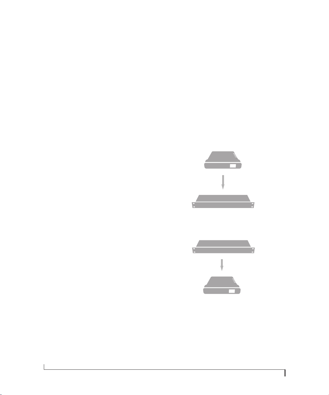
In the simplest case, you have two devices and one
is the word clock master and the other is the slave
as shown below in Figure 4-15 and Figure 4-16.
Figure 4-15: Slaving another digital audio device to the 8D via word
clock. For the 8D clock source, choose any source besides word clock,
as it is not advisable to chain word clock.
Figure 4-16: Slaving the 8D to word clock. For the 8D clock source,
choose ‘Word In’.
Daisy-chaining word clock
If necessary, you can daisy-chain several word
clock devices together. When doing so, connect
WORD CLOCK OUT from the first (master)
device to the WORD CLOCK IN on the second
device. Then connect its WORD CLOCK THRU
Master
Slave
Word clock OUT
Word clock IN
Other device
8D
Audio
clock
Master
Slave
Word clock master device
Word clock OUT
Word clock IN
8D
Loading ...
Loading ...
Loading ...