PREMIUM INVERTER SERIES(COOLING)
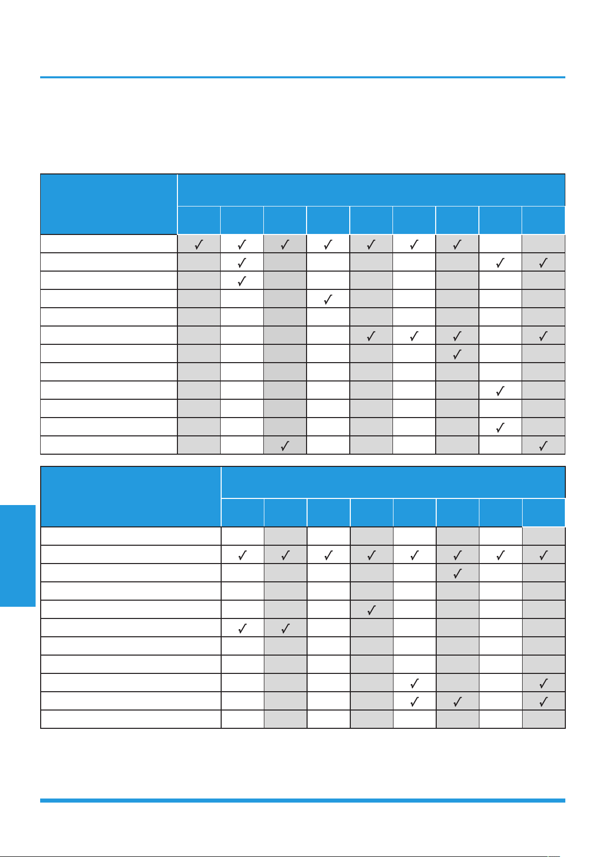
Models:
PIAW9164A/PIAW9165B
PIA12264A/PIA12265B
PIA18264A/PIA18265B


Table of Contents
Page
1. Safety Precautions ........................................................................................ 1
1. In case of Accidents or Emergency
2. Pre-Installation and Installation
3. Operation and Maintenance
2. Specifications ................................................................................................ 3
1. Model Reference
2. Electrical Wiring Diagrams
3. Product Features ........................................................................................... 10
1. Operation Modes and Functions
4. Maintenance and Disassembly .................................................................... 18
1. Maintenance
2. Disassembly
5. Troubleshooting ............................................................................................ 56
1. Safety Caution
2. General Troubleshooting
3. Error Diagnosis and Troubleshooting Without Error Code
4. Quick Maintenance by Error Code
5. Troubleshooting by Error Code
Appendix ............................................................................................................. 82
i) Temperature Sensor Resistance Value Table for T1,T2,T3 and T4 (°C – K)
ii) Temperature Sensor Resistance Value Table for TP (°C – K)
iii) △T(°F)
iV) Pressure On Service Port


Contents
1. In Case of Accidents or Emergency ......................................................................2
2. Pre-Installation .......................................................................................................2
3. Operation and Maintenance .................................................................................2
Safety Precautions

Safety
Precautions
Page 2
To prevent personal injury, or property or unit damage,
adhere to all precautionary measures and instructions
outlined in this manual. Before servicing a unit, refer to this
service manual and its relevant sections.
Failure to adhere to all precautionary measures listed in this
section may result in personal injury, damage to the unit or
to property, or in extreme cases, death.
WARNING indicates a potentially hazardous
situation which if not avoided could result in serious
personal injury, or death.
CAUTION indicates a potentially hazardous situation
which if not avoided could result in minor or
moderate personal injury, or unit damage.
1. In case of Accidents or Emergency
WARNING
•• If a gas leak is suspected, immediately turn off the
gas and ventilate the area if a gas leak is suspected
before turning the unit on.
•• If strange sounds or smoke is detected from the unit,
turn the breaker off and disconnect the power supply
cable.
•• If the unit comes into contact with liquid, contact an
authorized service center.
•• If liquid from the batteries makes contact with skin or
clothing, immediately rinse or wash the area well with
clean water.
•• Do not insert hands or other objects into the air inlet
or outlet while the unit is plugged in.
•• Do not operate the unit with wet hands.
•• Do not use a remote controller that has previously
been exposed to battery damage or battery leakage.
CAUTION
•• Clean and ventilate the unit at regular intervals when
operating it near a stove or near similar devices.
•• Do not use the unit during severe weather conditions.
If possible, remove the product from the window
before such occurrences.
2. Pre-Installation and Installation
WARNING
•• Use this unit only on a dedicated circuit.
•• Damage to the installation area could cause the unit
to fall, potentially resulting in personal injury, prop-
erty damage, or product failure.
•• Only qualified personnel should disassemble, install,
remove, or repair the unit.
•• Only a qualified electrician should perform electri-
cal work. For more information, contact your dealer,
seller, or an authorized Midea service center.
CAUTION
•• While unpacking be careful of sharp edges around
the unit as well as the edges of the fins on the con-
denser and evaporator.
3. Operation and Maintenance
WARNING
•• Do not use defective or under-rated circuit breakers.
•• Ensure the unit is properly grounded and that a
dedicated circuit and breaker are installed.
•• Do not modify or extend the power cable. Ensure
the power cable is secure and not damaged during
operation.
•• Do not unplug the power supply plug during
operation.
•• Do not store or use flammable materials near the
unit.
•• Do not open the inlet grill of the unit during
operation.
•• Do not touch the electrostatic filter if the unit is
equipped with one.
•• Do not block the inlet or outlet of air flow to the unit.
•• Do not use harsh detergents, solvents, or similar items
to clean the unit. Use a soft cloth for cleaning.
•• Do not touch the metal parts of the unit when
removing the air filter as they are very sharp.
•• Do not step on or place anything on the unit or
outdoor units.
•• Do not drink water drained from the unit
•• Avoid direct skin contact with water drained from the
unit.
•• Use a firm stool or step ladder according to
manufacturer procedures when cleaning or
maintaining the unit.
CAUTION
•• Do not install or operate the unit for an extended
period of time in areas of high humidity or in an
environment directly exposing it to sea wind or salt
spray.
•• Do not install the unit on a defective or damaged
installation stand, or in an unsecure location.
•• Ensure the unit is installed at a level position
•• Do not install the unit where noise or air discharge
created by the outdoor unit will negatively impact the
environment or nearby residences.
•• Do not expose skin directly to the air discharged by
the unit for prolonged periods of time.
•• Ensure the unit operates in areas water or other
liquids.
•• Ensure the drain hose is installed correctly to ensure
proper water drainage.
•• When lifting or transporting the unit, it is
recommended that two or more people are used for
this task.
•• When the unit is not to be used for an extended time,
disconnect the power supply or turn off the breaker.

Contents
1. Model Reference ....................................................................................................4
2. Electrical Wiring Diagrams ....................................................................................5
2.1 Indoor Unit ....................................................................................................5
2.2 Outdoor Unit .................................................................................................7
Specifications

Specifications
Page 4
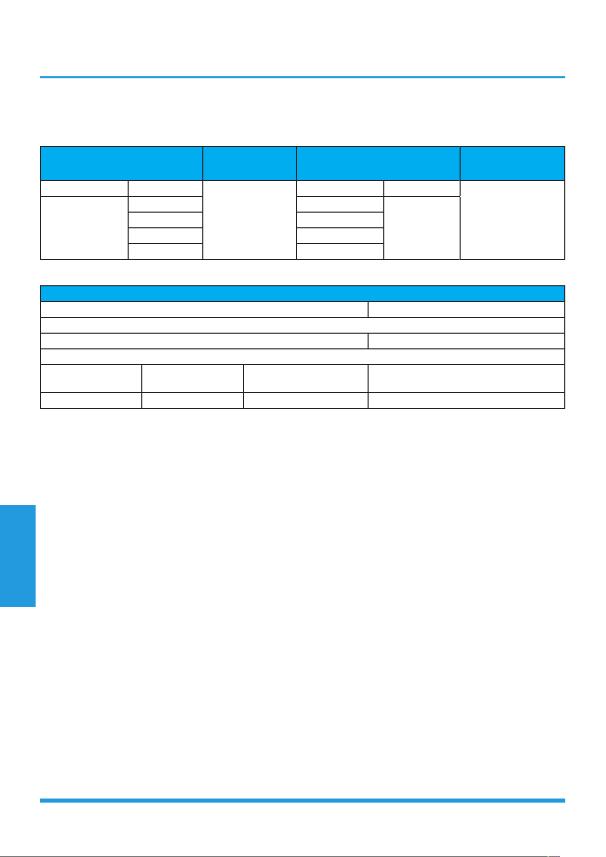
1. Model Reference
Refer to the following table to determine the specific indoor and outdoor unit model number of your purchased
equipment.
Indoor Unit Model Outdoor Unit Model Capacity (Btu) Power Supply
PIAW9164A PIAW9165B 9K
208/230V~, 60Hz, 1PhasePIA12264A PIA12265B 12K
PIA18264A PIA18265B 18K
Specifications
Page 5
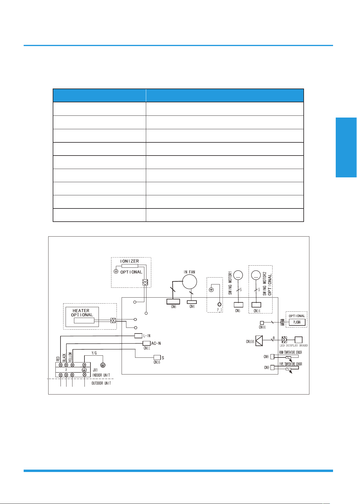
2. Electrical Wiring Diagrams
2.1 Indoor unit
Abbreviation Paraphrase
Y/G Yellow-Green Conductor
ION Positive and Negative Ion Generator
CAP Capacitor
PLASMA Electronic Dust Collector
L LIVE
N NEUTRAL
Heater The Electric Heating Belt of Indoor Unit
T1 Indoor Room Temperature
T2 Coil Temperature of Indoor Heat Exchanger Middle
PIAW9164A, PIA12264A
INDOOR WIRING DIAGRAM
M
M
~
3
3
CN13_1
CN12_1
CN13_2
CN12_2
M
RED
BLACK
2
1
3
16022000020314
Specifications
Page 6
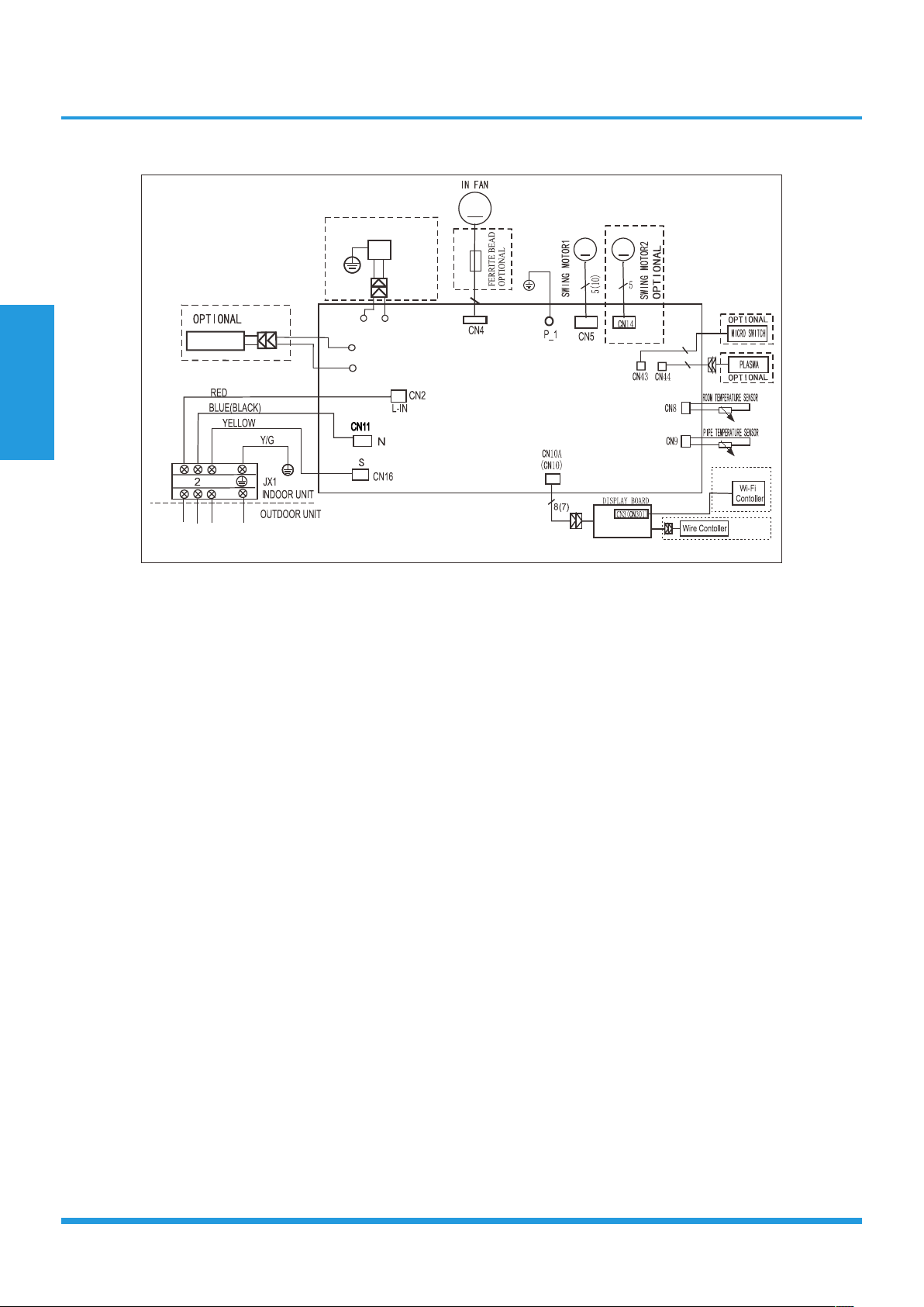
PIA18264A
INDOOR WIRING DIAGRAM
M
CN6_1
CN12_1
CN6
_2
CN12_2
M
M
5
2
2
16022000019694
I ON
OPTI ONAL
Y/ G
HEATER
1
3
OPTIONAL
OPTIONAL

Specifications
Page 7
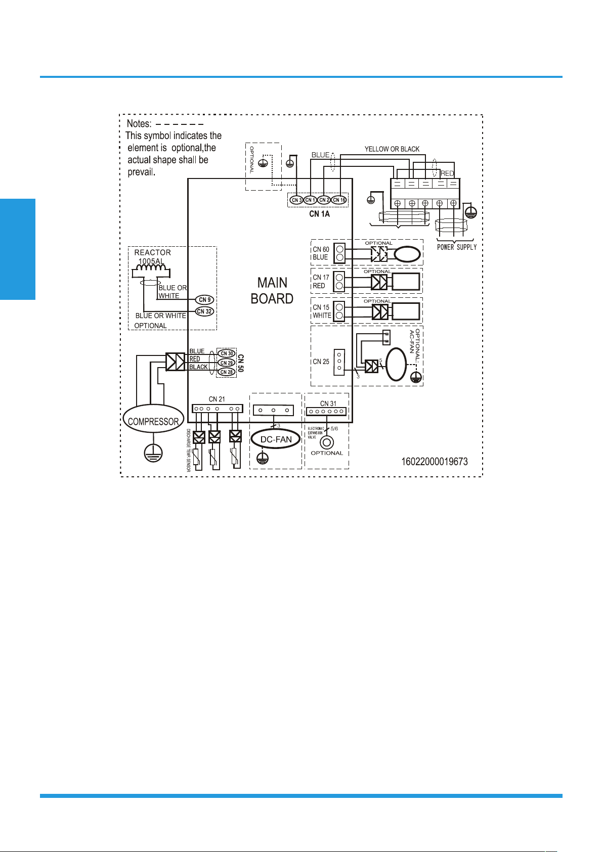
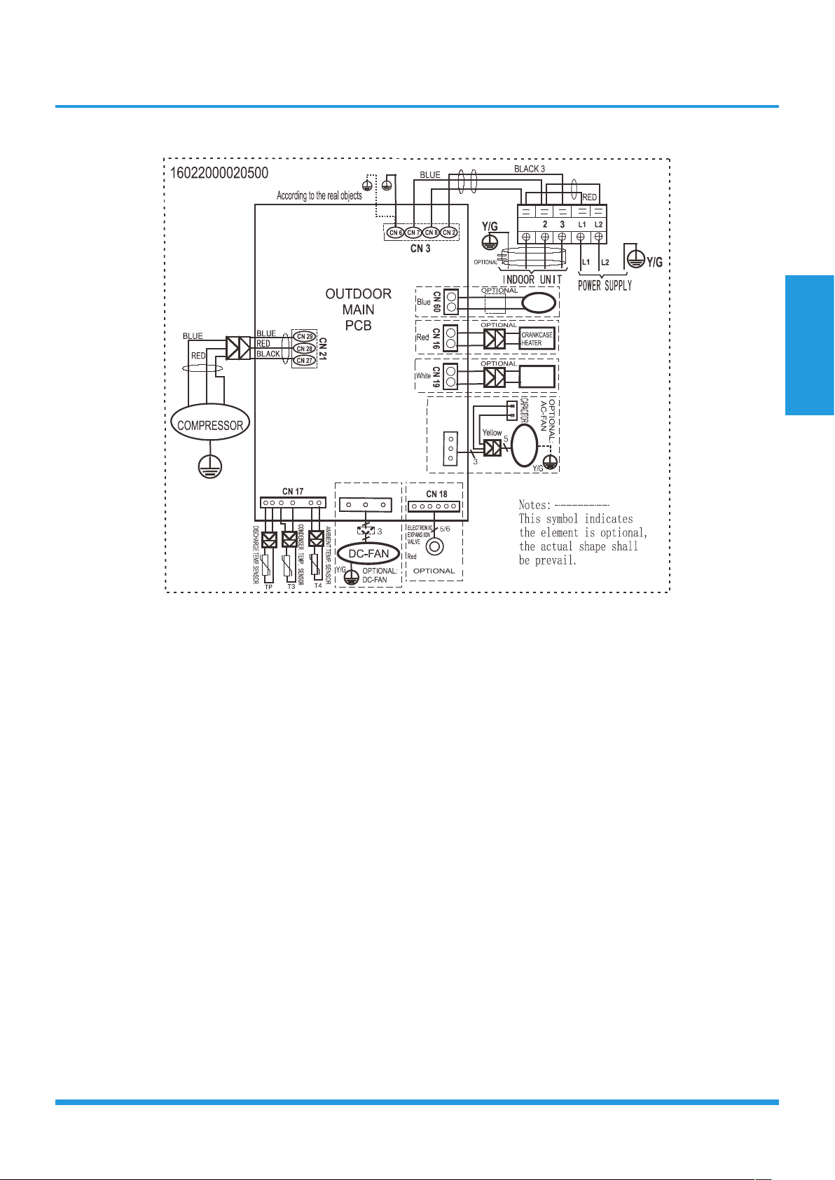
2.2 Outdoor Unit
Abbreviation Paraphrase
4-WAY Gas Valve Assembly/4-WAY VALVE
AC-FAN Alternating Current FAN
DC-FAN Direct Current FAN
CT1 AC Current Detector
COMP Compressor
L-PRO Low Pressure Switch
H-PRO High Pressure Switch
T3 Coil Temperature of Condenser
T4 Outdoor Ambient Temperature
TH Compressor Suction Temperature
TP Compressor Discharge Temperature
EEV Electronic Expansive Valve
Specifications
Page 8
PIAW9165B, PIA12265B
4-WAY
OPTIONAL:
DC-FAN
CN 7
PAN
HEATER
CRANKCASE
HEATER
BROWN
I NDOOR UNI T
3
2
L1
L2
BLUE OR BLACK
1
Y/G
AMBIENT TEMP. SENSOR
CONDENSER TEMP SENSOR.
Y/G
Y/G
Y/G
U
V
W
BLUE
RED
BLACK
AC-FAN
CAPACITOR
Y/G
Y/G
Y/G
Specifications
Page 9
PIA18265B
4-WAY
CN 414
PAN
HEATER
B
R
O
W
N
1
B
L
U
E
L
2
1
Y/GY/G
Y/G
U
V
W
BLACK
AC-FAN
CN 5
S

Contents
1. Operation Modes and Functions ........................................................................11
1.1 Abbreviation ................................................................................................11
1.2 Safety Features ............................................................................................11
1.3 Display Function ..........................................................................................12
1.4 Fan Mode ....................................................................................................12
1.5 Cooling Mode .............................................................................................12
1.6 Heating Mode .............................................................................................12
1.7 Auto-mode ..................................................................................................13
1.8 Drying Mode ...............................................................................................13
1.9 Forced Operation Function ..........................................................................13
1.10 Timer function .............................................................................................13
1.11 Sleep function .............................................................................................14
1.12 Auto-Restart Function ..................................................................................14
1.13 Refrigerant Leakage Detection .....................................................................14
1.14 Louver Position Memory Function ................................................................14
1.15 8°C Heating(Optional) ................................................................................14
1.16 Self Clean(Optional) ....................................................................................14
1.17 Follow Me(Optional) ...................................................................................14
1.18 Silence(Optional) .......................................................................................14
1.19 Information Inquiry ......................................................................................15
Product Features

Product Features
Page 11
1. Operation Modes and Functions
1.1 Abbreviation
Unit element abbreviations
Abbreviation Element
T1 Indoor room temperature
T2 Coil temperature of evaporator
T3 Coil temperature of condenser
T4 Outdoor ambient temperature
TS Set temperature
TP Compressor discharge temperature
1.2 Safety Features
Compressor three-minute delay at restart
Compressor functions are delayed for up to one minute
upon the first startup of the unit, and are delayed for up
to three minutes upon subsequent unit restarts.
Temperature protection of compressor top
The unit will stop working when the compressor top temp.
protector cut off, and will restart after the compressor top
temp. protector restart.
Automatic shutoff based on discharge temperature
If the compressor discharge temperature exceeds 115°C
for five seconds, the compressor ceases operation.
Automatic shutoff based on fan speed
If the indoor fan speed registers below 300RPM for an
extended period of time, the unit ceases operation and the
corresponding error code is displayed on the indoor unit.
Inverter module protection
The inverter module has an automatic shutoff mechanism
based on the unit’s current, voltage, and temperature.
If automatic shutoff is initiated, the corresponding error
code is displayed on the indoor unit and the unit ceases
operation.
Indoor fan delayed operation
• When the unit starts, the louver is automatically
activated and the indoor fan will operate after a period
of 7 seconds.
• If the unit is in heating mode, the indoor fan is
regulated by the anti-cold wind function.
Compressor preheating
Preheating is automatically activated when T4 sensor is
lower than 3°C.
Sensor redundancy and automatic shutoff
• If one temperature sensor malfunctions, the air
conditioner continues operation and displays the
corresponding error code, allowing for emergency use.
• When more than one temperature sensor is
malfunctioning, the air conditioner ceases operation.
Refrigerant leakage detection
This function is active only when cooling mode is selected.
It will detect if the compressor is being damaged by
refrigerant leakage or by compressor overload. This is
measured using the coil temperature of evaporator T2
when the compressor is in operation.
Zero crossing detection error protection
If AC detects time interval is not correct for continuous
240s, the unit will stop and the LED will display the failure.
The correct zero crossing signal time interval should be
between 6-13ms.
Product Features
Page 12
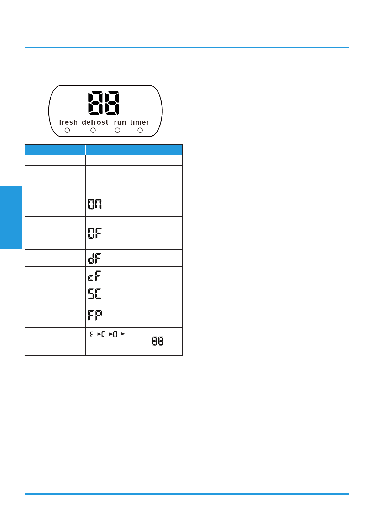
1.3 Display Function
Unit display functions
Function Display
Temperature Set temperature value
Temperature
(fan and Drying
mode)
Room temperature
Activation of Timer
ON, Fresh, Swing,
Turbo, or Silent
(3s)
Cancellation of
Timer OFF, Fresh,
Swing, Turbo, or
Silent
(3s)
Defrost
Warming in heating
mode
Self-clean (available
on select units only)
Heating in room
temperature
under 8°C
ECO function
(available on select
units only)
set temperature
gradually illuminates to
in
one second interval
1.4 Fan Mode
When fan mode is activated:
• The outdoor fan and compressor are stopped.
• Temperature control is disabled and no temperature
setting is displayed.
• The indoor fan speed can be set to high, med, low, or
auto.
• The louver operations are identical to those in cooling
mode.
• Auto fan: In fan-only mode, AC operates the same as
auto fan in cooling mode with the temperature set at
24°C.
1.5 Cooling Mode
1.5.1 Compressor Control
∆T is the programmed parameter of temperature
compensation.
• When T1-Ts < ∆T- 2 ℃, the compressor ceases
operation.
• When T1-Ts > ∆T+3℃, the compressor continues
operation.
• When the AC is operating in mute mode, the
compressor operates at a low frequency.
• When the current exceeds the preset value, the current
protection function activates and the compressor
ceases operation.
1.5.2 Indoor Fan Control
• In cooling mode, the indoor fan operates continuously.
The fan speed can be set to high, medium, low, or
auto.
• If the compressor ceases operations when the
configured temperature is reached, the indoor fan
motor operates at the minimum or configured speed.
1.5.3 Outdoor Fan Control
• The outdoor unit will be run at different fan speed
according to T4.
• For different outdoor units, the fan speeds are
different.
1.5.4 Condenser Temperature Protection
When condenser temperature is more than setting value,
the compressor will stop.
1.5.5 Evaporator Temperature Protection
When evaporator temperature drops below a configured
value, the compressor and outdoor fan ceases operations.
1.6 Heating Mode(for heat pump models)
1.6.1 Compressor Control
∆T is the programmed parameter of temperature
compensation.
• When T1-Ts>-∆T, the compressor ceases operation.
• When T1-TS<-∆T-1.5°C, the compressor continues
operation.
• When the AC is operating in mute mode, the
compressor operates at a low frequency.
• When the current exceeds the preset value, the current
protection function activates and the compressor
ceases operation.

Product Features
Page 13
1.6.2 Indoor Fan Control:
• When the compressor is on, the indoor fan can be set
to high/med/low/auto.
• When indoor unit coil temperature is low, the anti-cold
air function will start and indoor fan motor will run
at low speed, the speed can’t be changed ,when the
temperature is lower than setting value, the indoor fan
motor will stop.
• When the indoor temperature reaches the setting
temperature, the compressor will stop, the indoor
fan motor will run at the minimum speed or setting
speed.(The anti-cold air function is valid).
1.6.3 Outdoor Fan Control:
• The outdoor unit will be run at different fan speed
according to T4.
• For different outdoor units, the fan speeds are
different.
1.6.4 Defrosting mode
• The unit enters defrosting mode according to
changes in the temperature value of T3 as well as the
compressor running time.
• In defrosting mode, the compressor continues to run,
the indoor and outdoor motor will cease operation,
the defrost light of the indoor unit will turn on, and
the “
” symbol is displayed.
• If any one of the following conditions is satisfied,
defrosting ends and the machine switches to normal
heating mode:
• T3 rises above TCDE1°C.
• T3 maintained above TCDE2°C for 80 seconds.
• Unit runs for 15 minutes consecutively in defrosting
mode.
1.6.5 Evaporator Temperature Protection
When the evaporator temperature exceeds a preset
protection value, the compressor stops.
1.7 Auto-mode
• This mode can be selected with the remote controller
and the setting temperature can be changed between
17°C~30°C.
• In auto mode, the machine selects cooling, heating, or
fan-only mode on the basis of ∆T (∆T =T1-Ts).
∆T Running mode
∆T>2℃ Cooling
-2℃≤∆T≤2℃ Fan-only
∆T<-2℃ Heating*
Heating*: In auto mode, cooling only models run the fan
• The louver operates same as in relevant mode.
• If the machine switches mode between heating and
cooling, the compressor will keep stopping for certain
time and then choose mode according to T1-Ts.
• If the setting temperature is modified, the machine will
choose running function again.
1.8 Drying mode
• Indoor fan speed is fixed at breeze and can’t be
changed. The louver angle is the same as in cooling
mode.
• All protections are active and the same as that in
cooling mode.
1.9 Forced operation function
• Forced cooling mode:
The compressor and outdoor fan continue to run and
the indoor fan runs at low speed. After running for 30
minutes, the AC will switch to auto mode with a preset
temperature of 24°C.
• Forced auto mode:
Forced auto mode operates the same as normal auto mode
with a preset temperature of 24°C.
• The unit exits forced operation when it receives the
following signals:
• Switch on
• Switch off
• Timer on
• Timer off
• Changes in:
• mode
• fan speed
• sleeping mode
• Follow me
1.10 Timer function
• Timing range is 24 hours.
• Timer on. The machine will turn on automatically
when reaching the setting time.
• Timer off. The machine will turn off automatically
when reaching the setting time.
• Timer on/off. The machine will turn on
automatically when reaching the setting “on” time,
and then turn off automatically when reaching the
setting “off” time.

Product Features
Page 14
• Timer off/on. The machine will turn off
automatically when reaching the setting “off” time,
and then turn on automatically when reaching the
setting “on” time.
• The timer function will not change the AC current
operation mode. Suppose AC is off now, it will not
start up firstly after setting the “timer off” function.
And when reaching the setting time, the timer LED
will be off and the AC running mode has not been
changed.
• The setting time is relative time.
• The AC will quit the timer function when it has
malfunction
1.11 Sleep function
• The sleep function is available in cooling, heating or
auto mode.
• Operation process in sleep mode is as follow:
• When cooling, the setting temperature rises 1℃ (be
lower than 30℃) every one hour, 2 hours later the
setting temperature stops rising and the indoor fan is
fixed at low speed.
• When heating, the setting temperature decreases 1℃
(be higher than 17℃) every one hour, 2 hours later
the setting temperature stops rising and indoor fan is
fixed at low speed. (Anti-cold wind function has the
priority).
• Operation time in sleep mode is 7 hours. After 7 hours
the AC quits this mode and turns off.
• Timer setting is available.
1.12 Auto-Restart function
• The indoor unit has an auto-restart module that
allows the unit to restart automatically. The module
automatically stores the current settings (not including
the swing setting) and, in the case of a sudden power
failure, will restore those setting automatically within 3
minutes after power returns.
• If the unit was in forced cooling mode, it will run in
this mode for 30 minutes and turn to auto mode with
temperature set to 24°C.
• If there is a power failure while the unit is running, the
compressor starts 3 minutes after the unit restarts. If
the unit was already off before the power failure, the
compressor starts 1 minute after the unit restarts.
1.13 Refrigerant Leakage Detection
With this new technology, the display area will show “EC”
when the outdoor unit detects refrigerant leakage.
1.14 Louver Position Memory Function
When starting the unit again after shutting down, its
louver will restore to the angle originally set by the user,
but the precondition is that the angle must be within
the allowable range, if it exceeds, it will memorize the
maximum angle of the louver. During operation, if the
power fails or the end user shuts down the unit in the
turbo mode, the louver will restore to the default angle.
1.15 8°C Heating(Optional)
In heating mode, the temperature can be set to as low
as 8°C, preventing the indoor area from freezing if
unoccupied during severe cold weather.
1.16 Self clean(Optional)
• If you press “Self Clean” when the unit is in cooling or
drying mode:
• For cooling models, the indoor unit will run in low
fan mode for a certain time, then ceases operation.
• For heat pump models, the indoor unit will run in
fan-only mode, then low heat, and finally in fan-
only mode.
• Self Clean keeps the indoor unit dry and prevents
mold growth.
1.17 Follow me(Optional)
• If you press “Follow Me” on the remote, the indoor
unit will beep. This indicates the follow me function is
active.
• Once active, the remote control will send a signal
every 3 minutes, with no beeps. The unit automatically
sets the temperature according to the measurements
from the remote control.
• The unit will only change modes if the information
from the remote control makes it necessary, not from
the unit’s temperature setting.
• If the unit does not receive a signal for 7 minutes or
you press “Follow Me,” the function turns off. The
unit regulates temperature based on its own sensor
and settings.
1.18 Silence (Optional)
Press “Silence” on the remote control to enable the
SILENCE function. While this function is active, the
compressor frequency is maintained at a lower level than
F2. The indoor unit will run at faint breeze, which reduces
noise to the lowest possible level.

Product Features
Page 15
1.19 Information Inquiry
• To enter information inquiry status, complete the
following procedure within ten seconds:
• Press LED 3 times.
• Press SWING 3 times.
• If you are successful, you will hear beeps for two
seconds.
• Use the LED and SWING buttons to cycle through
information displayed.
• Pressing LED will display the next code in the
sequence. Pressing SWING will show the previous.
• The table next shows information codes. The screen
will display this code for two seconds, then the
information for 25 seconds.

Product Features
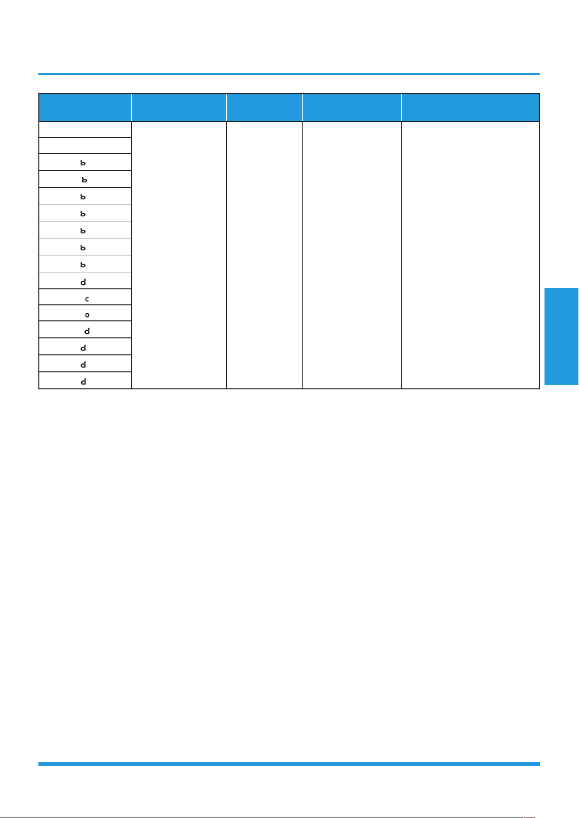
Page 16
Displayed code Explanation
Displayed
value
Meaning Additional Notes
T1
T2
T3
T4
Tb
TP
TH
FT
Fr
Room temperature
-1F,-1E,-1d,-1c,-
1b,-1A
-19—99
A0,A1,…A9
b0,b1,…b9
c0,c1,…c9
d0,d1,…d9
E0,E1,…E9
F0,F1,…F9
-25,-24,-23,-22,
-21,-20
-19—99
100,101,…109
110,111,…119
120,121,…129
130,131,…139
140,141,…149
150,151,…159
1. All displayed temperatures
use actual values.
2. All temperatures are
displayed in °C regardless
of remote used.
3. T1, T2, T3, T4, and T2B
display ranges from -25 to
70 °C. TP display ranges
from -20 to 130 °C.
4. The frequency display
ranges from 0 to 159HZ.
5. If the actual values exceed
or fall short of the defined
range, the values closest
to the maximum and
minimum values will be
displayed.
Indoor coil
temperature
Outdoor coil
temperature
Ambient
temperature
Outlet temperature
of indoor coil
Discharge
temperature
Suction temperature
Targeted frequency
Actual frequency
IF
Indoor fan speed
0
1,2,3,4
14-FF
OFF
Low speed, Medium
speed, High speed,
Turbo.
Actual fan speed is
equal to the display
value converted to
decimal value and
multiplied by 10. This
is measured in RPM.
N/A
Used for some large capacity
motors.
Used for some small capacity
motors.
The display value is 14-FF
(hexadecimal). The
corresponding fan speed
ranges from 200 to 2550RPM.
OF
Outdoor fan speed
LA
EXV opening angle 0-FF
Actual EXV opening
value is equal to
the display value
converted to decimal
value and then
multiplied by 2.
-
CT
Compressor
continuous running
time
0-FF 0-255 minutes
If the actual value exceeds
or falls short of the defined
range, the value closest to the
maximum and minimum will
be displayed.
ST
Causes of
compressor stop
0-99
For a detailed
explanation, contact
technical support.
-
Product Features
Page 17
Displayed code Explanation
Displayed
value
Meaning Additional Notes
A0
Reserved
0-FF
2-28
5-20
5-25
- -
A1
0
1
2
3
4
5
6
L
A
U
T
A
5
T

Contents
1. Maintenance ........................................................................................................19
1.1 First Time Installation Check ........................................................................19
1.2 Refrigerant Recharge ...................................................................................21
1.3 Re-Installation .............................................................................................22
1.3.1 Indoor Unit ..................................................................................22
1.3.2 Outdoor Unit ...............................................................................24
2. Disassembly .........................................................................................................26
2.1 Indoor Unit ..................................................................................................26
2.2 Outdoor Unit ...............................................................................................42
Maintenance and Disassembly
Maintenance and
Disassembly
Page 19
1. Maintenance
1.1 First Time Installation Check
Air and moisture trapped in the refrigerant system affects
the performance of the air conditioner by:
• Increasing pressure in the system.
• Increasing the operating current.
• Decreasing the cooling or heating efficiency.
• Congesting the capillary tubing due to ice build-up in
the refrigerant circuit.
• Corroding the refrigerant system.
To prevent air and moisture from affecting the air
conditioner’s performance, the indoor unit, as well as the
pipes between the indoor and outdoor unit, must be be
leak tested and evacuated.
Leak test (soap water method)
Use a soft brush to apply soapy water or a neutral liquid
detergent onto the indoor unit connections and outdoor
unit connections. If there is gas leakage, bubbles will form
on the connection.
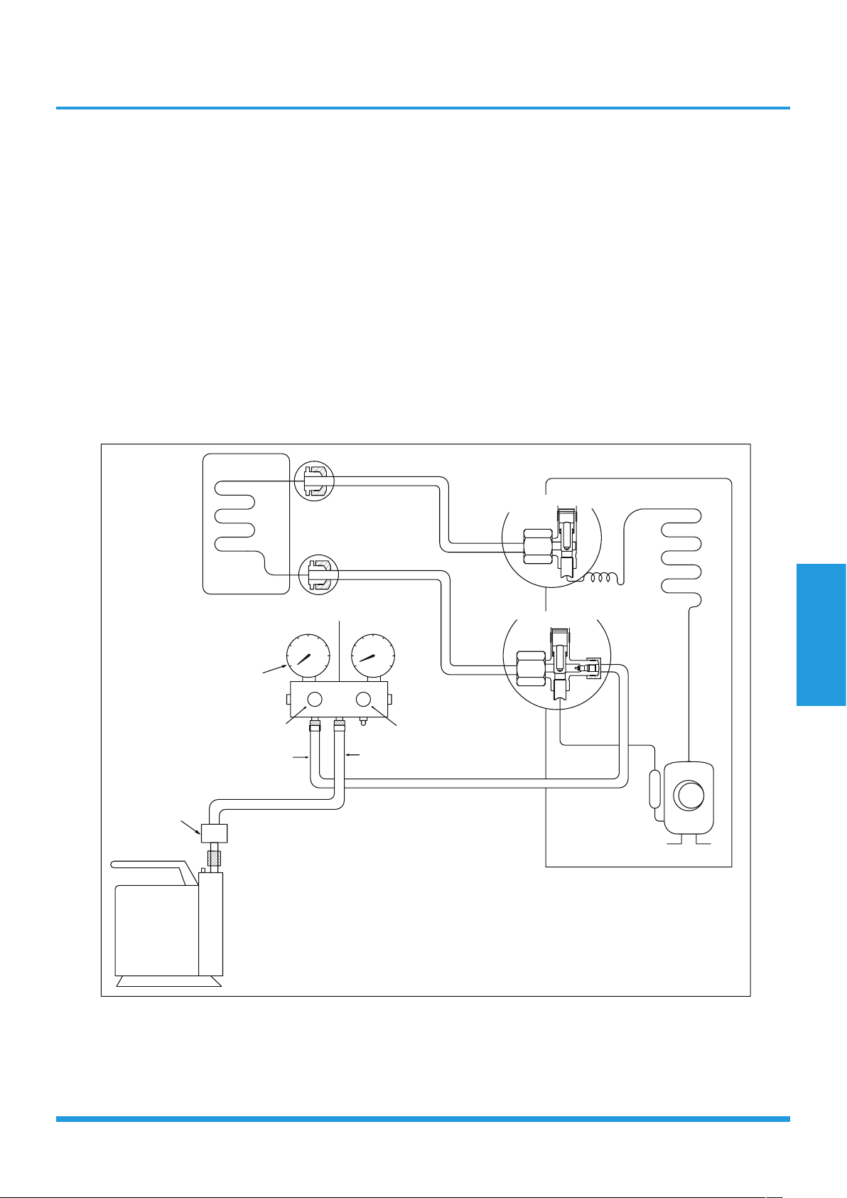
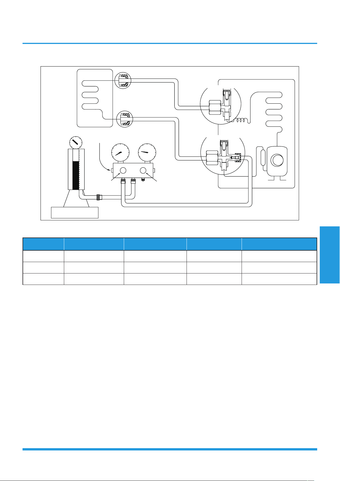
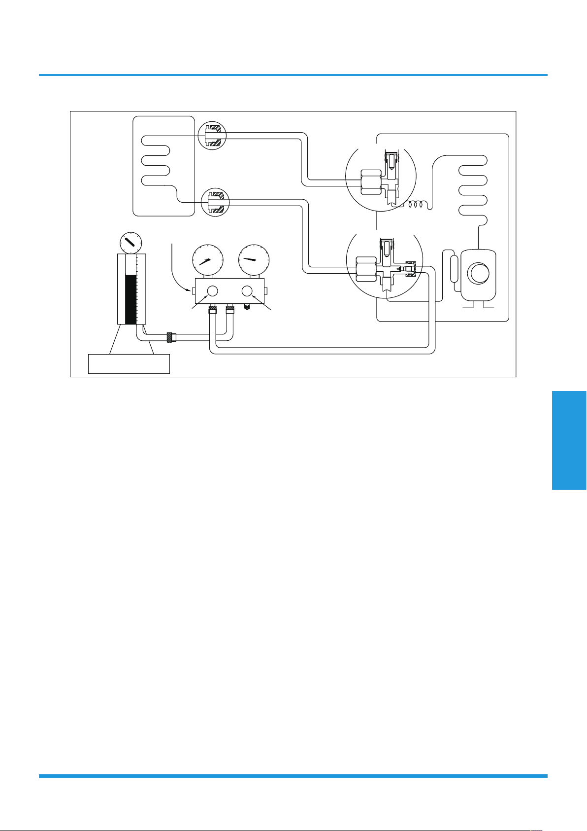
Air purging with vacuum pump
/TJUUX[TOZ
2OW[OJYOJK
-GYYOJK
:]U]G_\GR\K
:NXKK]G_\GR\K
5[ZJUUX[TOZ
)RUYK
)RUYK
3GTOLURJ\GR\K
36G
6XKYY[XK
MG[MK
.GTJRK2U
.GTJRK.O
)NGXMKNUYK
)NGXMKNUYK
<GI[[S
V[SV
<GI[[S
V[SV
)USVU[TJSKZKX
2U
.O

Maintenance and
Disassembly
Page 20
Procedure:
1. Tighten the flare nuts of the indoor and outdoor
units, and confirm that both the 2- and 3-way valves
are closed.
2. Connect the charge hose with the push pin of Handle
Lo to the gas service port of the 3-way valve.
3. Connect the charge hose of Handle Hi connection to
the vacuum pump.
4. Fully open the Handle Lo manifold valve.
5. Using the vacuum pump, evacuate the system for
30 minutes.
a. Check whether the compound meter indicates
-0.1 MPa (14.5 Psi).
• If the meter does not indicate -0.1 MPa
(14.5 Psi) after 30 minutes, continue
evacuating for an additional 20 minutes.
• If the pressure does not achieve -0.1 MPa
(14.5 Psi) after 50 minutes, check for leakage.
• If the pressure successfully reaches -0.1 MPa
(14.5 Psi), fully close the Handle Lo valve and
cease vacuum pump operations.
b. Wait for 5 minutes then check whether the gauge
needle moves after turning off the vacuum pump.
6. Loosen the flare nut of the 3-way valve for 6 or
7 seconds and then tighten the flare nut again.
a. Confirm the pressure display in the pressure
indicator is slightly higher than the atmospheric
pressure.
b. Remove the charge hose from the 3-way valve.
7. Fully open the 2- and 3-way valves and tighten the
cap of the 3-way valve.
Maintenance and
Disassembly
Page 21
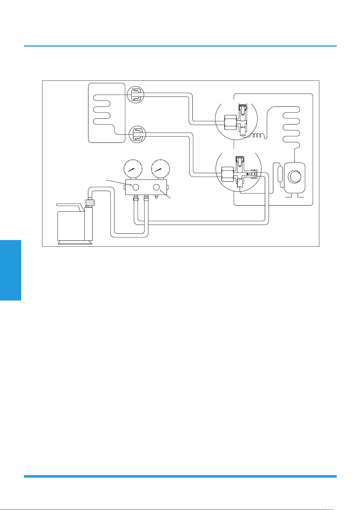
1.2 Refrigerant Recharge
/TJUUX[TOZ
2OW[OJYOJK
-GYYOJK
)NKIQ\GR\K
56+4
)259+
)NGXMOTM
:]U]G_\GR\K
:NXKK]G_\GR\K
5[ZJUUX[TOZ
5VKT
5VKT
2U
.O
+RKIZXUTOIYIGRK
I_ROTJKX
Prior to recharging the refrigerant, confirm the additional amount of refrigerant required using the following table:
Models Standard length Max. elevation Max. length Additional refrigerant
9k&12k 7.5m (24.6ft) 10m (32.8ft) 25m (82ft) 15g/m (0.16oz/ft)
18k 7.5m (24.6ft) 20m (65.6ft) 30m (98.4ft) 15g/m (0.16oz/ft)
24k 7.5m (24.6ft) 25m (82ft) 50m (164ft) 30g/m (0.32oz/ft)
Procedure:
1. Close both 2- and 3-way valves.
2. Slightly connect the Handle Lo charge hose to the
3-way service port.
3. Connect the charge hose to the valve at the bottom
of the cylinder.
4. If the refrigerant is R410A, invert the cylinder to
ensure a complete liquid charge.
5. Open the valve at the bottom of the cylinder for 5
seconds to purge the air in the charge hose, then fully
tighten the charge hose with push pin Handle Lo to
the service port of 3-way valve..
6. Place the charging cylinder onto an electronic scale
and record the starting weight.
7. Fully open the Handle Lo manifold valve, 2- and
3-way valves.
8. Operate the air conditioner in cooling mode to charge
the system with liquid refrigerant.
9. When the electronic scale displays the correct weight
(refer to the gauge and the pressure of the low
side to confirm), turn off the air conditioner, then
disconnect the charge hose from the 3-way service
port immediately..
10. Mount the caps of service port and 2- and 3-way
valves.
11. Use a torque wrench to tighten the caps to a torque
of 18 N.m.
12. Check for gas leakage.
Maintenance and
Disassembly
Page 22
1.3 Re-Installation
1.3.1 Indoor Unit
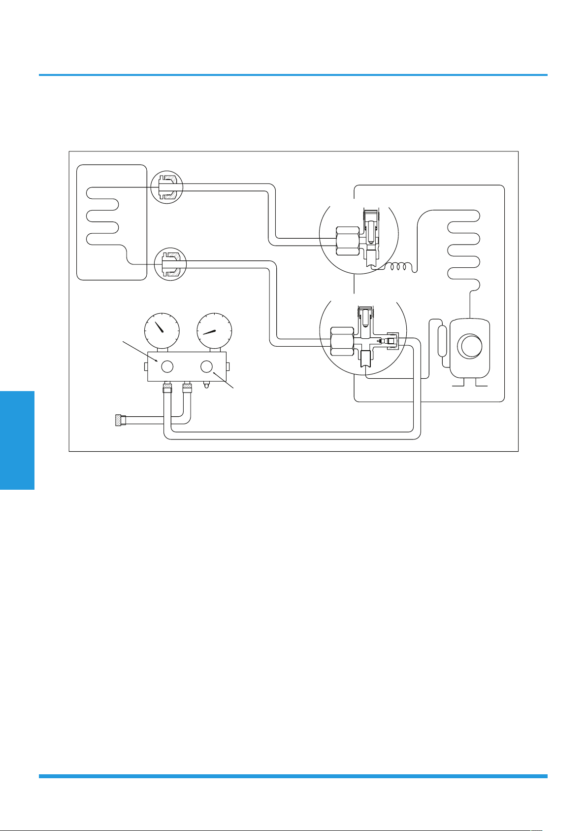
Collecting the refrigerant into the outdoor unit
/TJUUX[TOZ
2OW[OJYOJK
-GYYOJK
)RUYK
)RUYK
:]U]G_\GR\K
:NXKK]G_\GR\K
5[ZJUUX[TOZ
5VKT
)RUYK
2U
.O
Procedure:
1. Confirm that the 2- and 3-way valves are opened.
2. Remove the valve stem caps and ensure that the valve
stems are opened (use as hexagonal wrench to open
the valve stems).
3. Connect the charge hose with the push pin of Handle
Lo to the 3-way valve’s gas service port.
4. Open the Handle Lo valve of the manifold valve to
purge air from the charge hose for 5 seconds and
then close it quickly.
5. Close the 2-way valve.
6. Operate the air conditioner in cooling mode. Cease
operations when the gauge reaches 0.1 MPa
(14.5 Psi).
7. Close the 3-way valve so that the gauge rests
between 0.3 MPa (43.5 Psi) and 0.5 MPa (72.5 Psi).
8. Disconnect the charge set, and tighten the 2- and
3-way valve’s stem nuts (use a torque wrench to
tighten the 3-way valves service port cap to a torque
of 18 N.m).
9. Check for gas leakage.
Maintenance and
Disassembly
Page 23
Air purging with vacuum pump
/TJUUX[TOZ
2OW[OJYOJK
-GYYOJK
:]U]G_\GR\K
:NXKK]G_\GR\K
5[ZJUUX[TOZ
)RUYK
)RUYK
3GTOLURJ\GR\K
36G
6XKYY[XK
MG[MK
.GTJRK2U
.GTJRK.O
)NGXMKNUYK
)NGXMKNUYK
<GI[[S
V[SV
<GI[[S
V[SV
)USVU[TJSKZKX
2U
.O
Procedure:
1. Tighten the flare nuts of the indoor and outdoor
units, and confirm that both the 2- and 3-way valves
are closed.
2. Connect the charge hose with the push pin of Handle
Lo to the gas service port of the 3-way valve.
3. Connect the charge hose of Handle Hi connection to
the vacuum pump.
4. Fully open the Handle Lo manifold valve.
5. Using the vacuum pump, evacuate the system for
30 minutes.
a. Check whether the compound meter indicates
-0.1 MPa (14.5 Psi).
• If the meter does not indicate -0.1 MPa (14.5 Psi)
after 30 minutes, continue evacuating for an
additional 20 minutes.
• If the pressure does not achieve -0.1 MPa
(14.5 Psi) after 50 minutes, check for leakage.
• If the pressure successfully reaches -0.1 MPa
(14.5 Psi), fully close the Handle Lo valve and
cease vacuum pump operations.
b. Wait for 5 minutes then check whether the gauge
needle moves after turning off the vacuum pump.
6. Loosen the flare nut of the 3-way valve for 6 or
7 seconds and then tighten the flare nut again.
c. Confirm the pressure display in the pressure
indicator is slightly higher than the atmospheric
pressure.
d. Remove the charge hose from the 3-way valve.
7. Fully open the 2- and 3-way valves and tighten the
cap of the 3-way valve.
Maintenance and
Disassembly
Page 24
1.3.2 Outdoor Unit
Evacuation for the whole system
/TJUUX[TOZ
2OW[OJYOJK
-GYYOJK
56+4
)259+
:]U]G_\GR\K
:NXKK]G_\GR\K
5[ZJUUX[TOZ
5VKT
5VKT
2U
.O
<GI[[SV[SV
Procedure:
1. Confirm that the 2- and 3-way valves are opened.
2. Connect the vacuum pump to the 3-way valve’s
service port.
3. Evacuate the system for approximately one hour.
Confirm that the compound meter indicates
-0.1 MPa (14.5Psi).
4. Close the valve (Low side) on the charge set and turn
off the vacuum pump.
5. Wait a period of five minutes then check whether the
gauge needle moves after turning off the vacuum
pump.
6. Disconnect the charge hose from the vacuum pump.
Maintenance and
Disassembly
Page 25
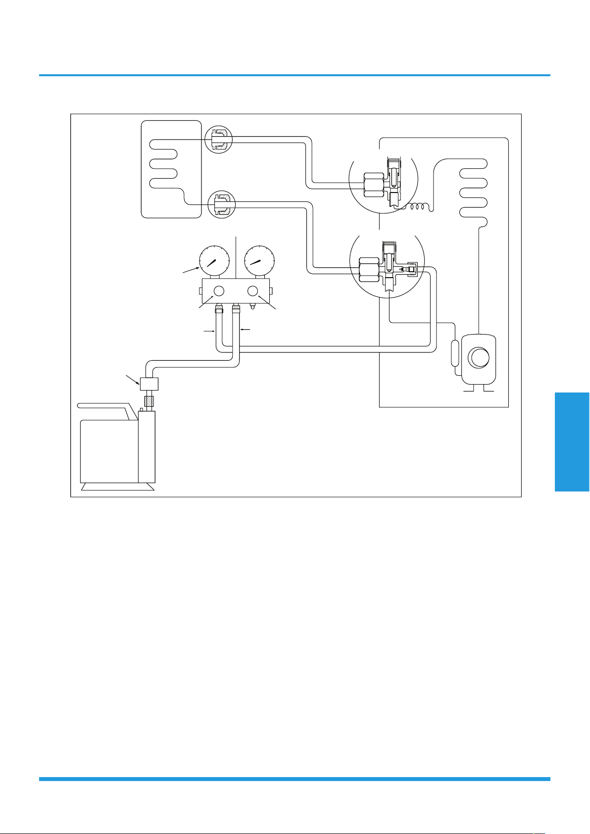
Refrigerant charging
/TJUUX[TOZ
2OW[OJYOJK
-GYYOJK
)NKIQ\GR\K
56+4
)259+
)NGXMOTM
:]U]G_\GR\K
:NXKK]G_\GR\K
5[ZJUUX[TOZ
5VKT
5VKT
2U
.O
+RKIZXUTOIYIGRK
I_ROTJKX
Procedure:
1. Connect the charge hose to the 3-way service port
and then open the 2- and the 3-way valves.
2. Connect the charge hose to the valve at the bottom
of the cylinder.
3. If the refrigerant is R410A, invert the cylinder to
ensure a complete liquid charge.
4. Open the valve at the bottom of the cylinder and close
the check valve on the charge set to purge the air.
5. Place the charging cylinder onto an electronic scale
and record the starting weight.
6. Operate the air conditioner in cooling mode.
7. Open the valves (Low side) on the charge set and
charge the system with liquid refrigerant.
8. When the electronic scale displays the correct weight
(refer to the gauge and the pressure of the low side
to confirm), disconnect the charge hose from the
3-way valve’s service port immediately and turn off
the air conditioner before disconnecting the hose.
9. Mount the valve stem caps and the service port.
10. Use a torque wrench to tighten the service port cap to
a torque of 18 N.m.
11. Check for gas leakage.
Note: 1. Mechanical connectors used indoors shall comply with local regulations.
2. When mechanical connectors are reused indoors, sealing parts shall be renewed. When flared joints
are reused indoors, the flare part shall be re-fabricated.
Maintenance and
Disassembly
Page 26
2. Disassembly
2.1 Indoor unit
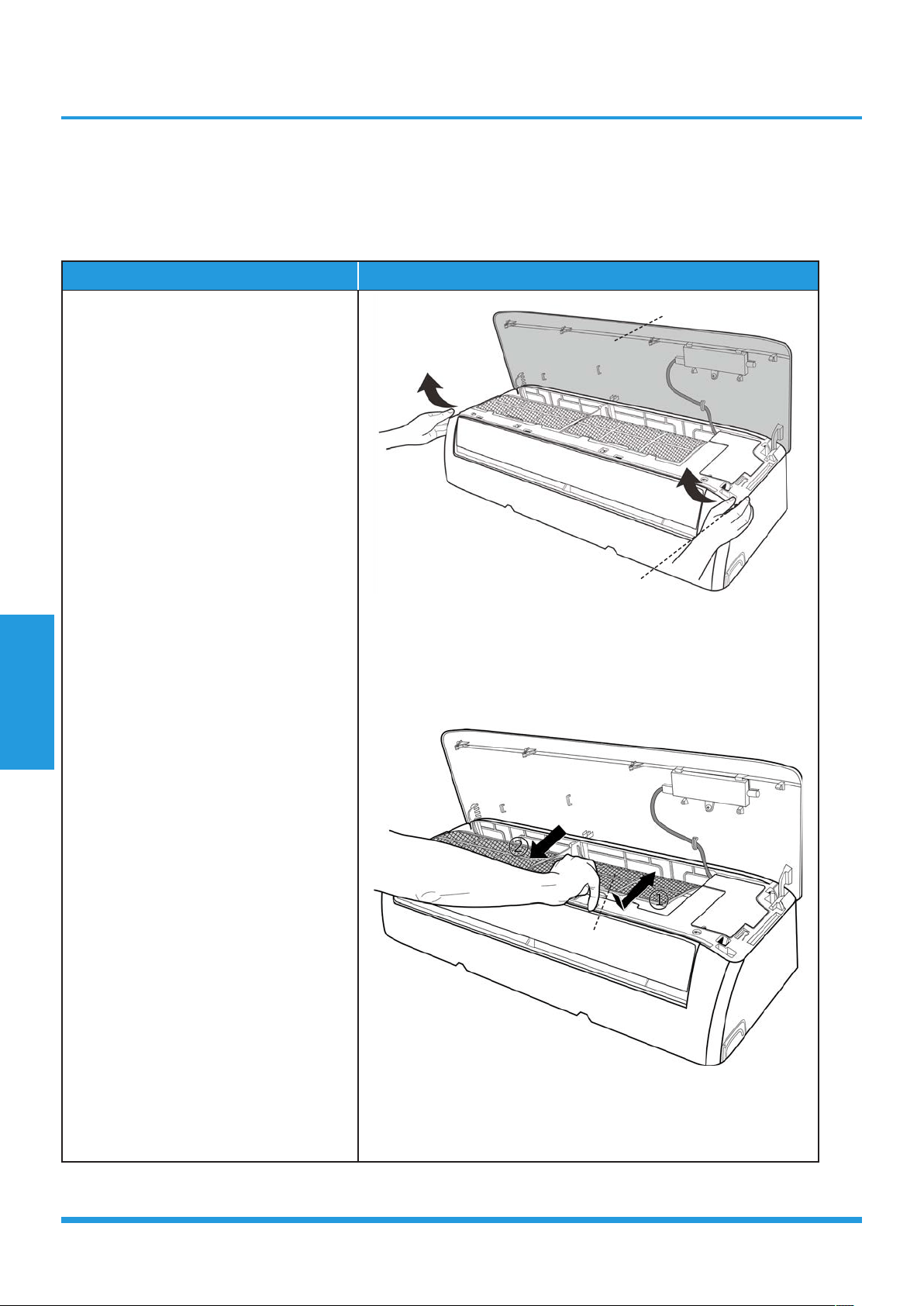
1. Front Panel
Procedure Illustration
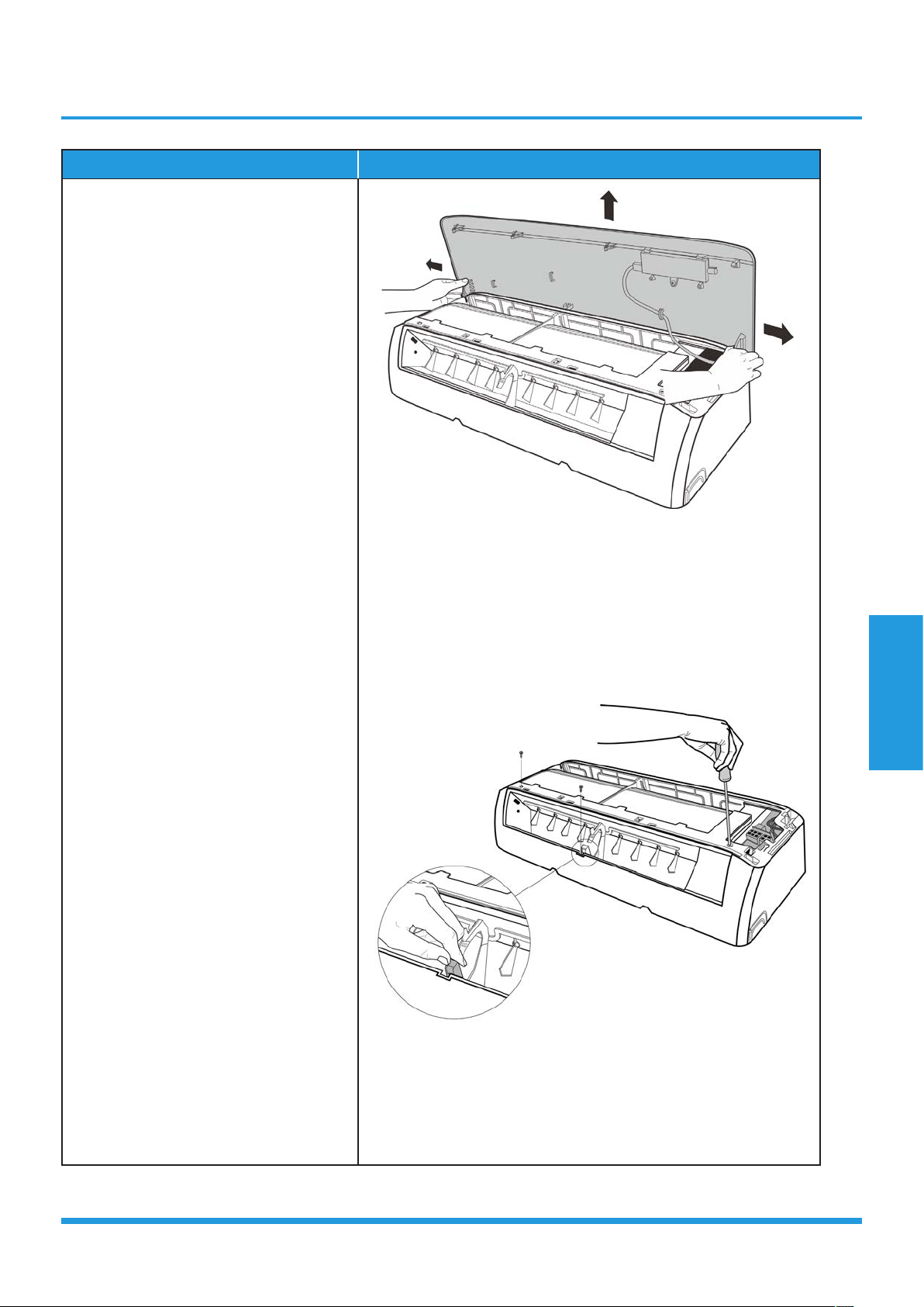
1) Hold the front panel by the tabs on
the both sides and lift it (see CJ_AB_
INV_001).
2) Push up the bottom of an air
filter (step 1), and then pull it out
downwards (step 2) (see CJ_AB_
INV_002).
CJ_AB_INV_001
CJ_AB_INV_002
Note: This section is for reference only. Actual unit appearance may vary.
Front Panel
Tab
Filter
Maintenance and
Disassembly
Page 27
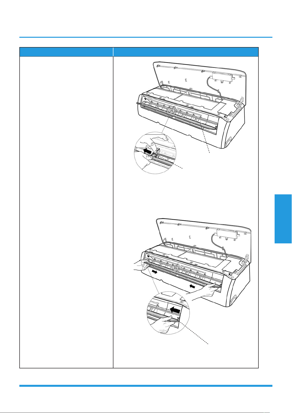
Procedure Illustration
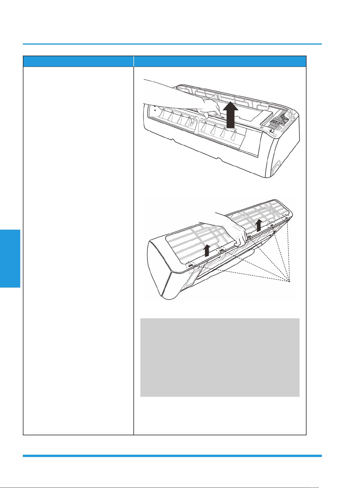
3) Open the horizontal louver and push
the hook towards left to open it (see
CJ_AB_INV_003).
4) Bend the horizontal louver lightly by
both hands to loosen the hooks, then
remove the horizontal louver (see
CJ_AB_INV_004).
CJ_AB_INV_003
CJ_AB_INV_004
Note: This section is for reference only. Actual unit appearance may vary.
Hook
Horizontal Louver
Hook
Maintenance and
Disassembly
Page 28
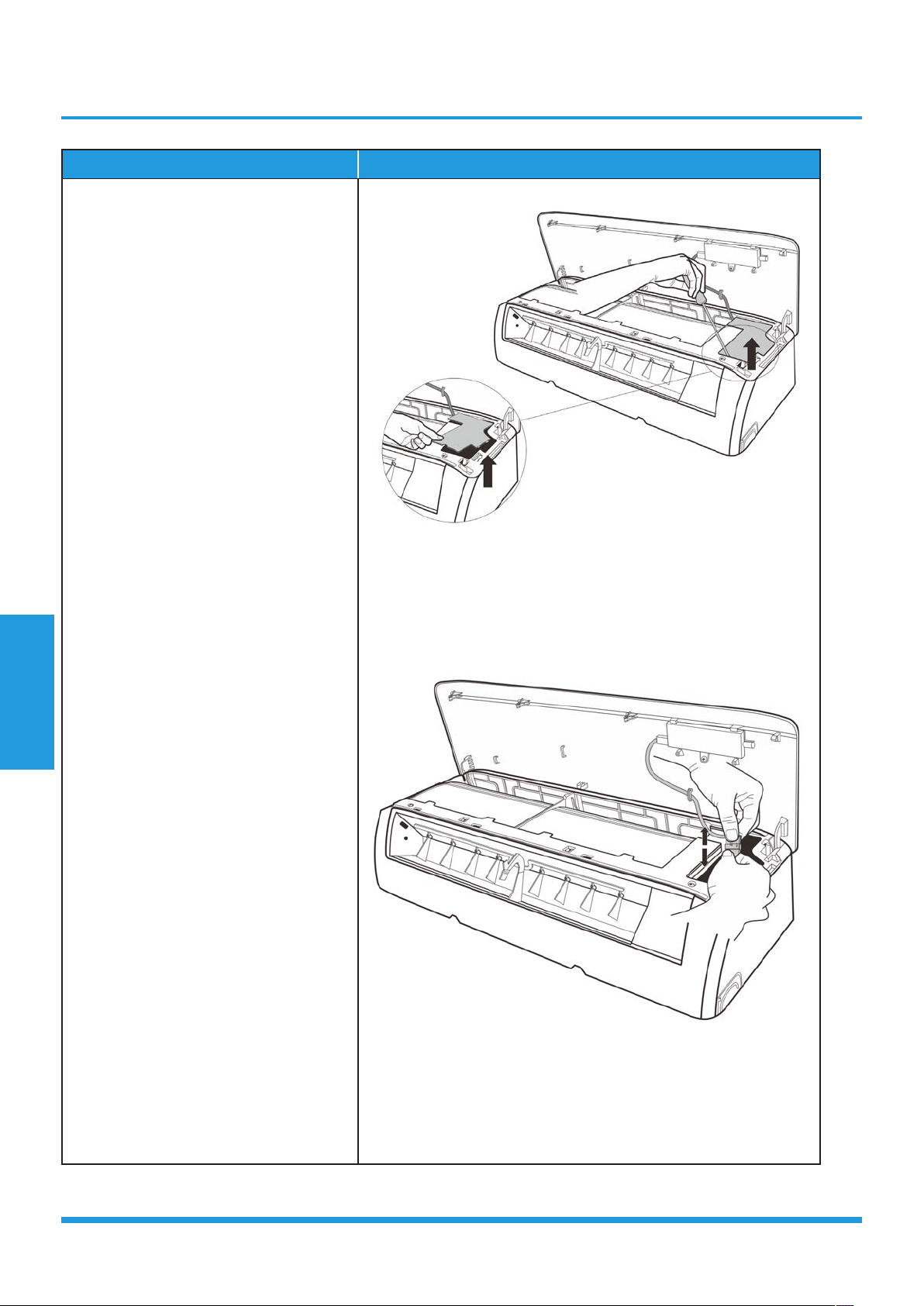
Procedure Illustration
5) Pry the electrical cover by a screw
driver, and rotate it towars left, then
remove it. (see CJ_AB_INV_005).
6) Disconnect the connector for display
board. (see CJ_AB_INV_006) .
CJ_AB_INV_005
CJ_AB_INV_006
Note: This section is for reference only. Actual unit appearance may vary.
Maintenance and
Disassembly
Page 29
Procedure Illustration
7) Slid the front panel side to side to
release each axis (see CJ_AB_INV_007)
8) Open the screw cap and then remove
the 3 screws (see CJ_AB_INV_008).
CJ_AB_INV_007
CJ_AB_INV_008
Note: This section is for reference only. Actual unit appearance may vary.
CJ_AF_INV_011-1
Maintenance and
Disassembly
Page 30
Procedure Illustration
9) Release the hooks with hands. (see
CJ_AB_INV_009)
10) Release the 5 hooks in the back (see
CJ_AB_INV_010).
11) Pull out the panel frame while
pushing the hook through a clearance
between the panel frame and the heat
exchanger. (see CJ_AB_INV_011)
CJ_AB_INV_009
CJ_AB_INV_010
CJ_AB_INV_011
Note: This section is for reference only. Actual unit appearance may vary.
Hooks
Maintenance and
Disassembly
Page 31
Procedure Illustration
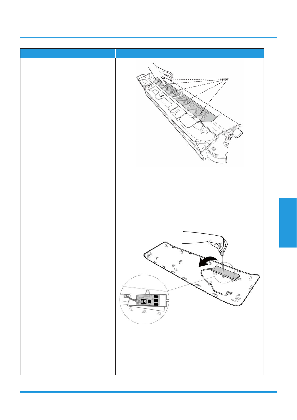
12) Release the 5 hooks of the vertical
blades, then pull the vertical blades
rightward and remove it (see CJ_AB_
INV_012).
13) Remove 1 screw of the display board.
(see CJ_AB_INV_013).
14) Rotate the display board in the
direction shown in the right picture.
(see CJ_AB_INV_013).
CJ_AB_INV_012
CJ_AB_INV_013
Note: This section is for reference only. Actual unit appearance may vary.
Hooks
Maintenance and
Disassembly
Page 32
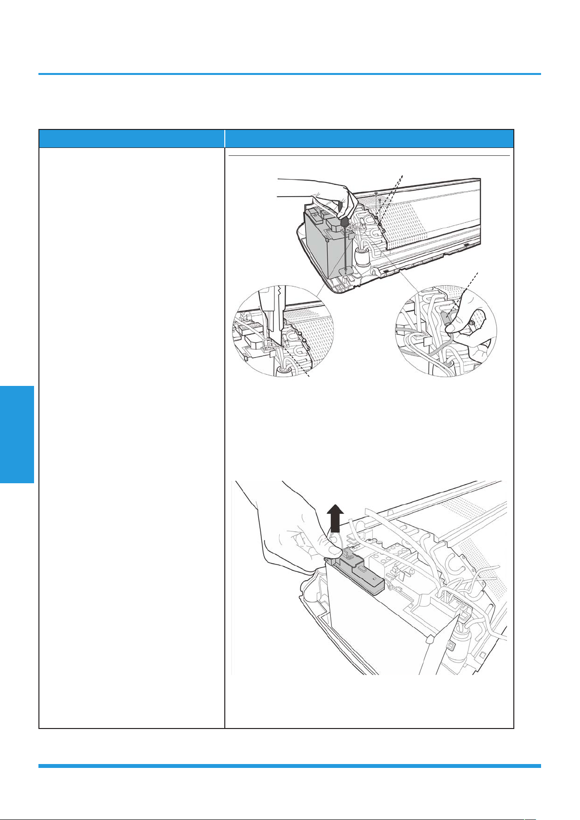
2. Electrical parts (Antistatic gloves must be worn.)
Note: Remove the front panel (refer to 1. Front panel) before disassembling electrical parts.
Procedure Illustration
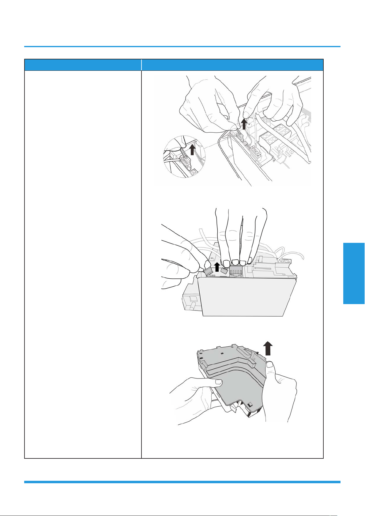
1) Cut the ribbon by a shear, then pull
out the coil temperature sensor (T2)
(see CJ_AB_INV_014).
2) Remove one fixing screw of the
electronic control box and two screws
used for the ground connection (see
CJ_AB_INV_014).
3) An upward force is maintained until
the cover of electronic control box is
removed (see CJ_AB_INV_015).
CJ_AB_INV_014
CJ_AB_INV_015
Note: This section is for reference only. Actual unit appearance may vary.
Ribbon
T2 Sensor
Ground Screws
Maintenance and
Disassembly
Page 33
Procedure Illustration
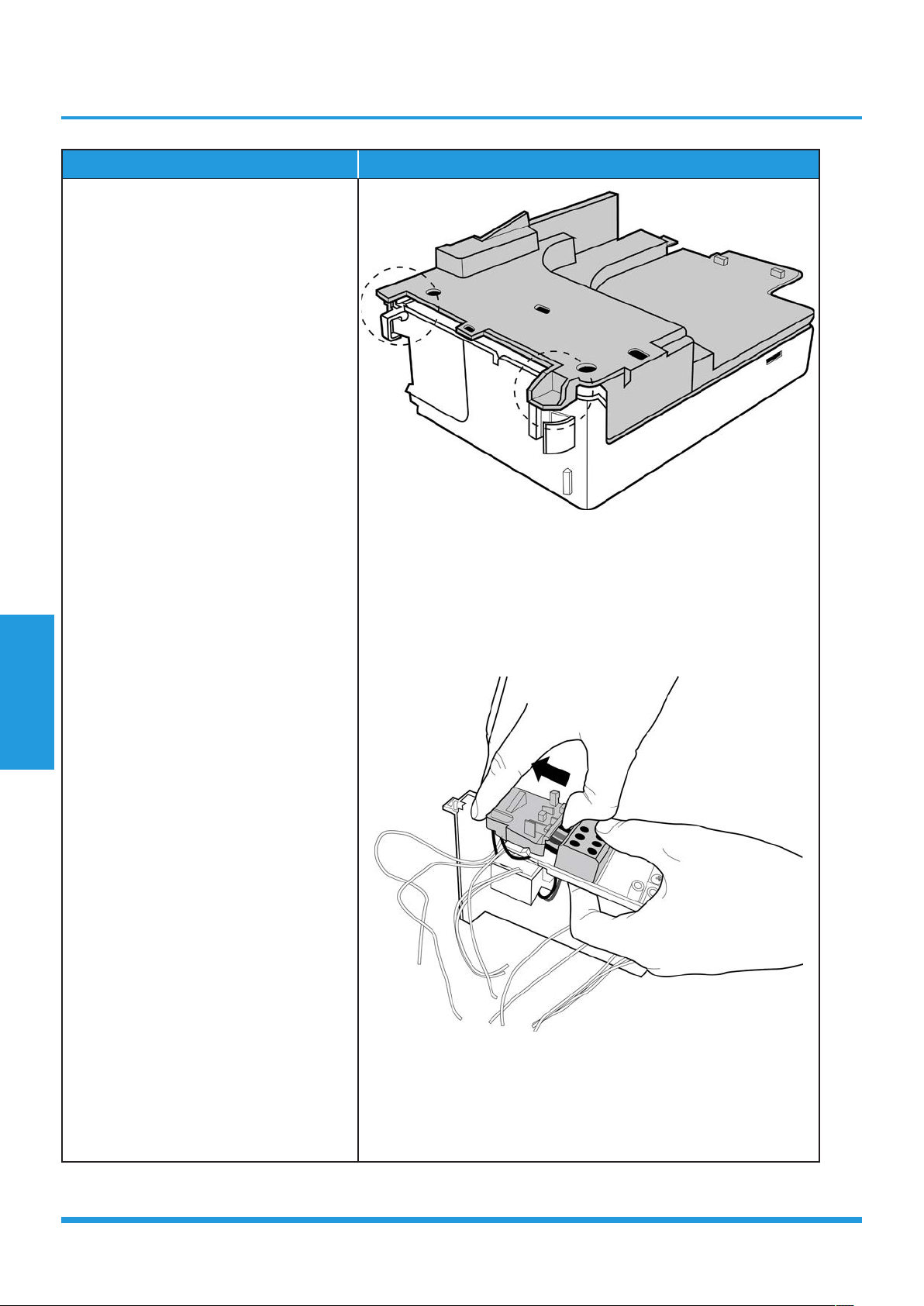
4) Remove the fixed devices of the
connectors (see CJ_AB_INV_016).
5) Disconnect the connectors of fan
motor, the step motor and the T2
sensor (see CJ_AB_INV_017).
6) Open the left side plate of electronic
control box (see CJ_AB_INV_018).
CJ_AB_INV_016
CJ_AB_INV_017
CJ_AB_INV_018
Note: This section is for reference only. Actual unit appearance may vary.
Maintenance and
Disassembly
Page 34
Procedure Illustration
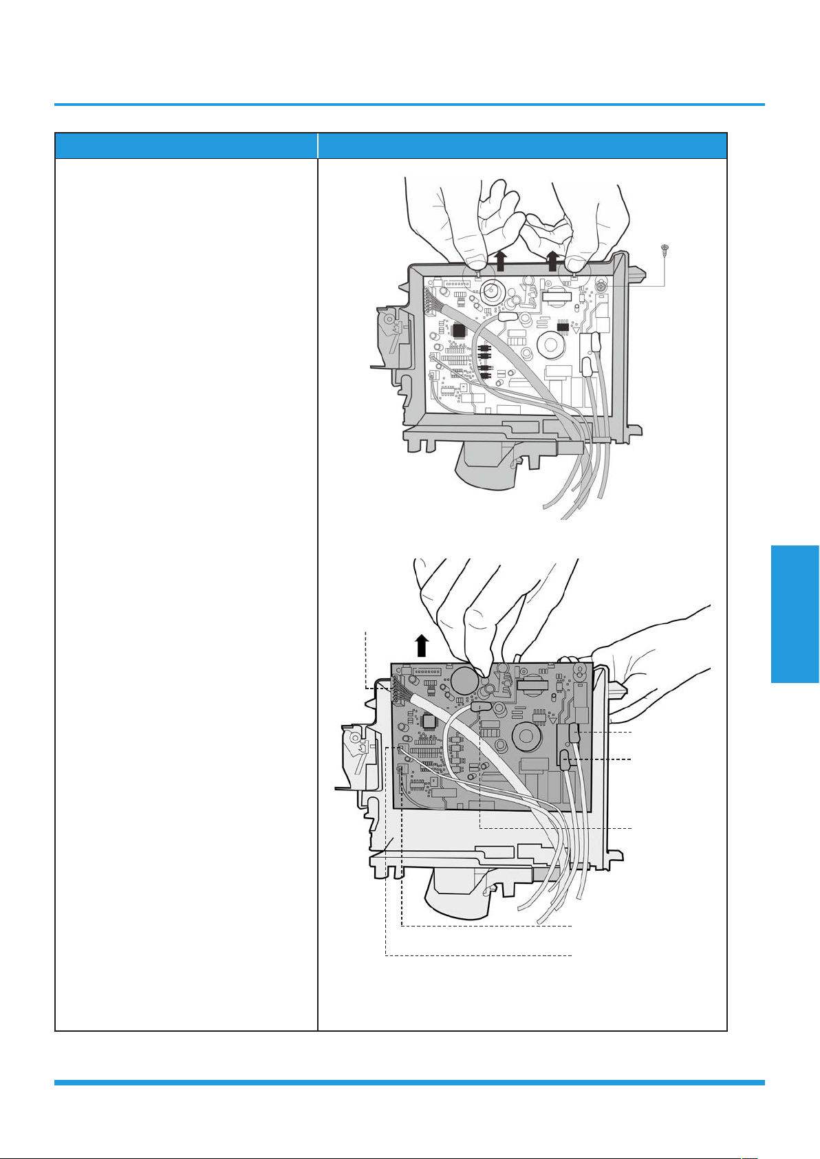
7) Open the two clips on the front of the
electric box. (see CJ_AB_INV_019)
8) Open the upper cover plate of
electronic control box (see CJ_AB_
INV_020).
CJ_AB_INV_019
CJ_AB_INV_020
Note: This section is for reference only. Actual unit appearance may vary.
Maintenance and
Disassembly
Page 35
Procedure Illustration
9) Remove 1 screw and open the 2 clips
along the direction indicated in right
image (see CJ_AB_INV_021).
10) Pull out the electrical main board
along the direction indicated in right
image to remove it (see CJ_AB_
INV_022).
CJ_AB_INV_021
CJ_AB_INV_022
Note: This section is for reference only. Actual unit appearance may vary.
Display board
Terminal (1L)
Terminal (W)
Terminal (S)
Pipe Temperature Sensor
Room Temperature Sensor
Maintenance and
Disassembly
Page 36
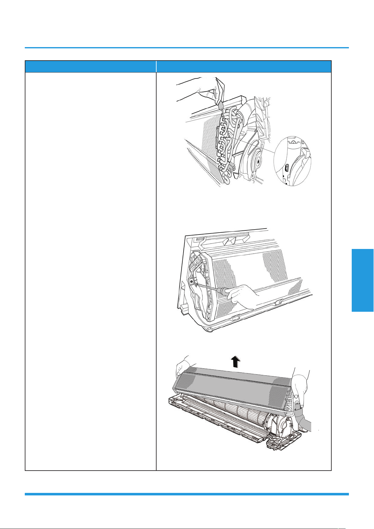
3. Evaporator
Note: Remove the front panel and electrical parts (refer to 1. Front panel and 2. Electrical parts) before
disassembling evaporator.
Procedure Illustration
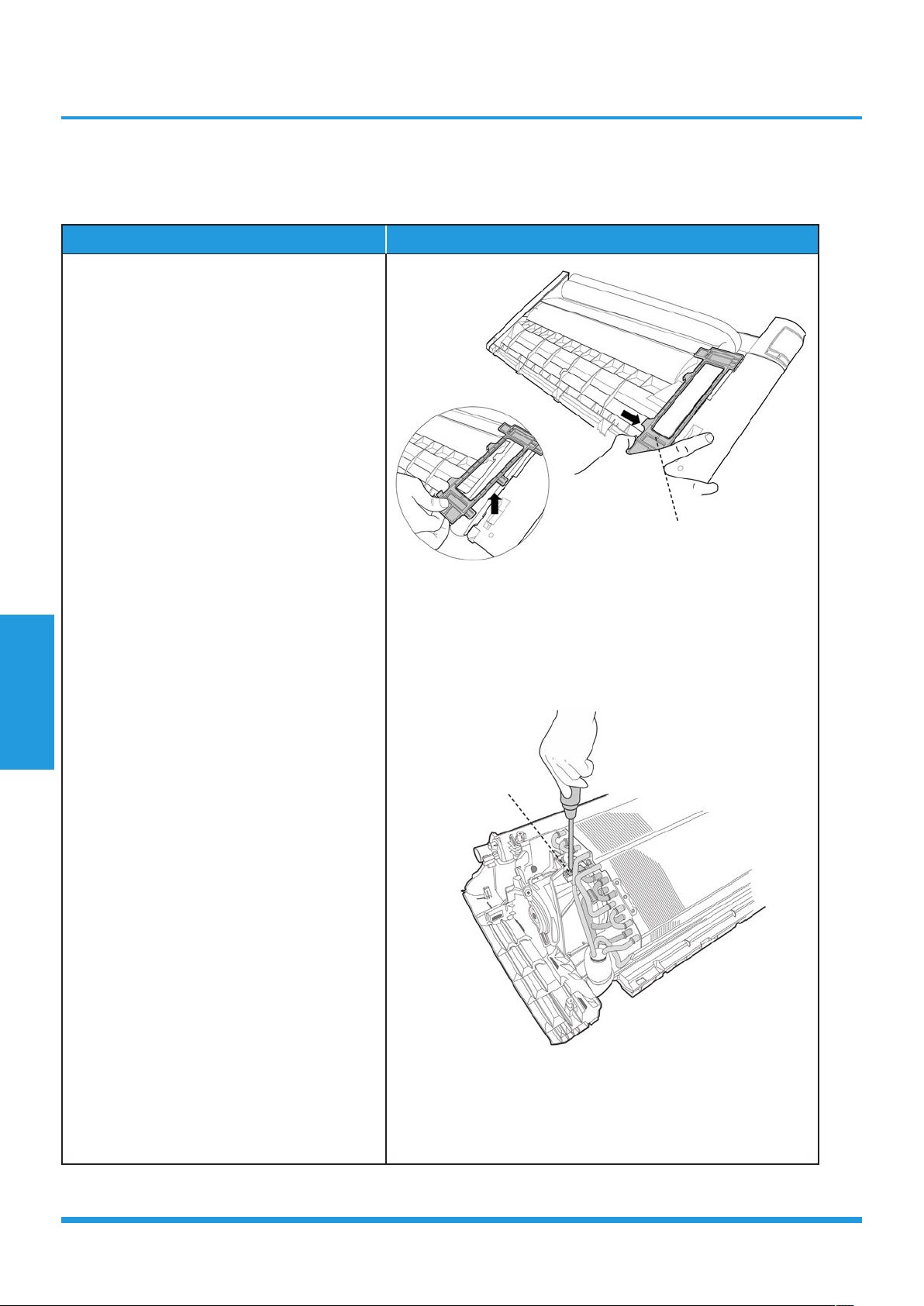
1) Disassemble the pipe holder located at the
rear of the unit (see CJ_AB_INV_023).
2) Remove the 1 screws on the evaporator
located at the fixed plate (see CJ_AB_
INV_024).
CJ_AB_INV_023
CJ_AB_INV_024
Note: This section is for reference only. Actual unit appearance may vary.
Pipe Holder
Screw
Maintenance and
Disassembly
Page 37
Procedure Illustration
3) Release the hook on the evaporator (see
CJ_AB_INV_025).
4) Remote the one screw on the evaporator
located at the fixed plate (see CJ_AB_
INV_026).
5) Pull out the evaporator (see CJ_AB_
INV_027).
CJ_AB_INV_025
CJ_AB_INV_026
CJ_AB_INV_027
Note: This section is for reference only. Actual unit appearance may vary.
Maintenance and
Disassembly
Page 38
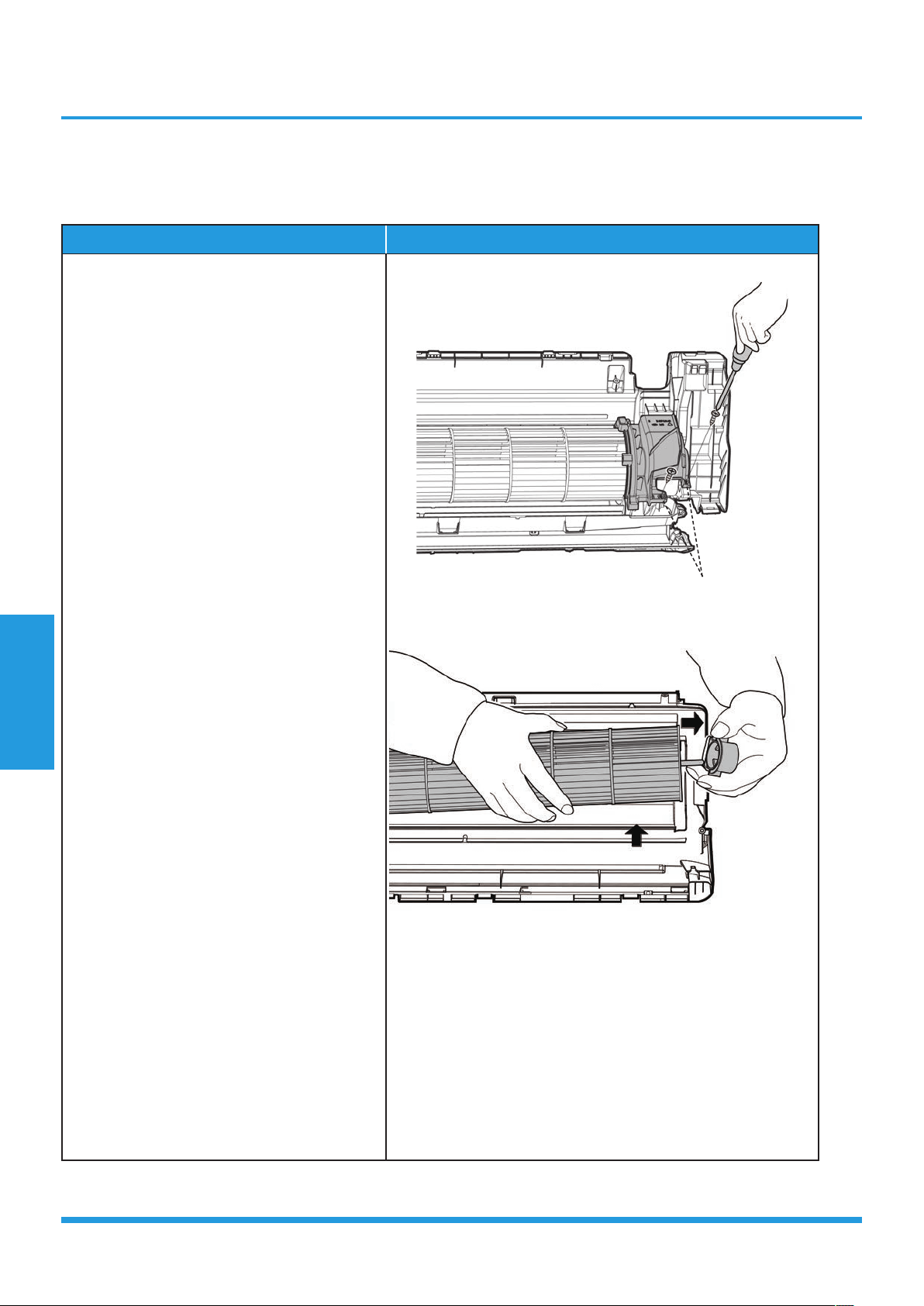
4. Fan motor and fan
Note: Remove the front panel, electrical parts and evaporator (refer to 1. Front panel, 2. Electrical parts, and
3. Evaporator). before disassembling fan motor and fan.
Procedure Illustration
1) Remove the two screws and remove the
fixing board of the fan motor (see CJ_AB_
INV_028).
2) Remove the bearing sleeve (see CJ_AB_
INV_029).
CJ_AB_INV_028
CJ_AB_INV_029
Note: This section is for reference only. Actual unit appearance may vary.
Screws
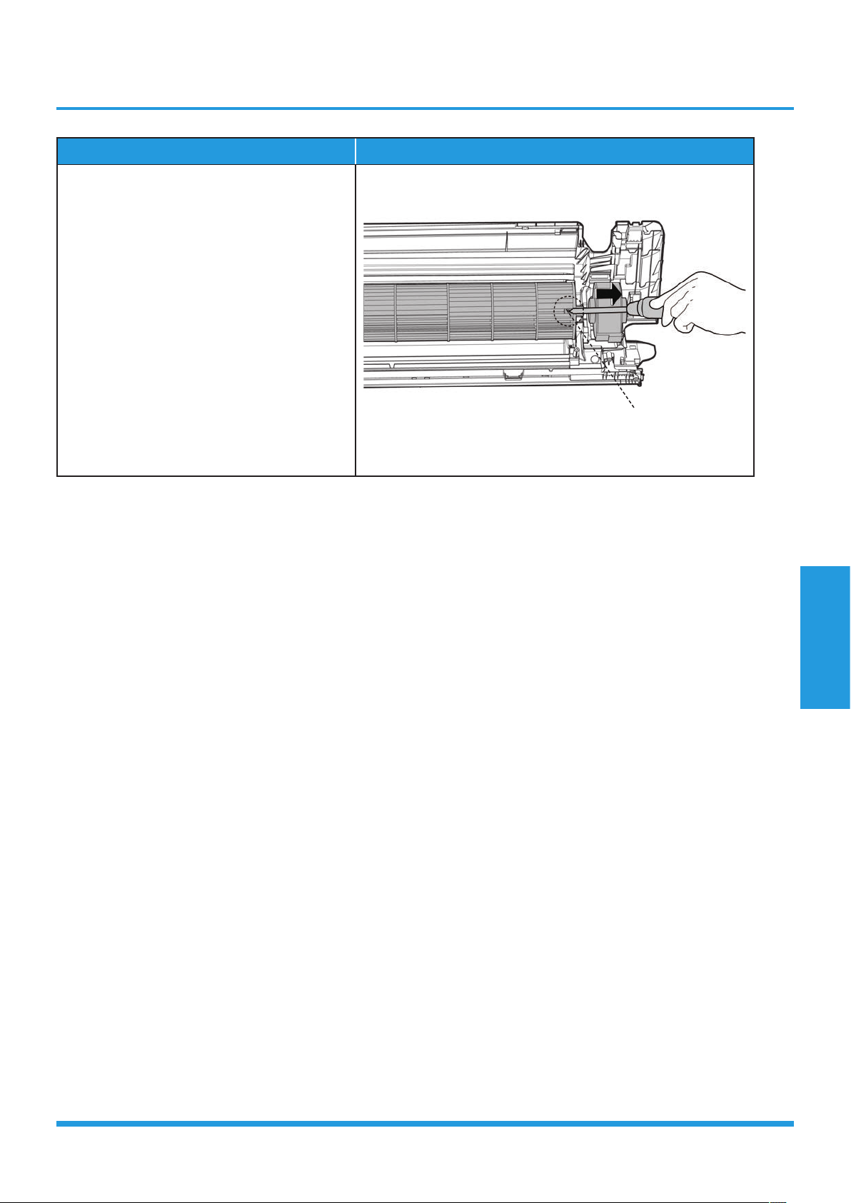
Maintenance and
Disassembly
Page 39
Procedure Illustration
3) Remove the fixing screw (see CJ_AB_
INV_030).
4) Pull out the fan motor and fan assembly
from the side.
CJ_AB_INV_030
Note: This section is for reference only. Actual unit appearance may vary.
Fixing Screw

Maintenance and
Disassembly
Page 40
5. Step motor
Note: Remove the front panel and electrical parts (refer to 1. Front panel, 2. Electrical parts) before
disassembling step motor.
Procedure Illustration
1) Remove the two screws, then remove the
stepping motor (see CJ_AB_INV_031).
CJ_AB_INV_031
Note: This section is for reference only. Actual unit appearance may vary.
Stepping Motor
Maintenance and
Disassembly
Page 41
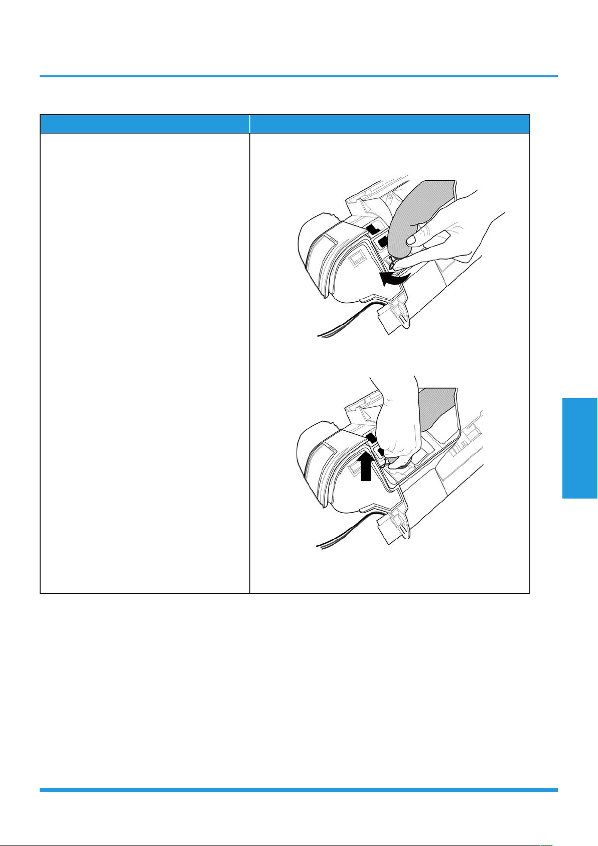
6. Drain Hose
Procedure Illustration
1) Rotate the fixed wire clockwise indicated
in right image (see CJ_AB_INV_032).
2) Pull up the drain hose to remove it (see
CJ_AB_INV_033).
CJ_AB_INV_032
CJ_AB_INV_033
Note: This section is for reference only. Actual unit appearance may vary.
Maintenance and
Disassembly
Page 42
2.2 Outdoor unit
1. Panel Plate
PIAW9165B, PIA12265B , PIA18265B
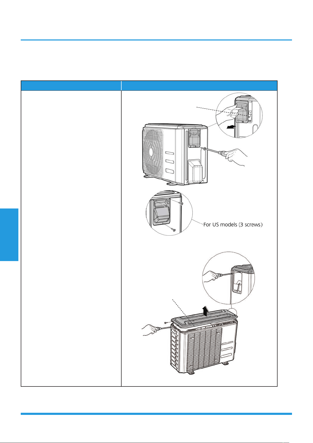
Procedure Illustration
1) Turn off the air conditioner and the
power breaker.
2) Remove the screws of the big handle
and then remove the big handle
(1 screws) (see CJ_BA30_001).
3) Remove the screws of the top cover
and then remove the top cover (3
screws). One of the screws is located
underneath the big handle (see CJ_
BA30_002).
CJ_BA30_001
CJ_BA30_002
Note: This section is for reference only. Actual unit appearance may vary.
Top Cover
Big Handle
Maintenance and
Disassembly
Page 43
Procedure Illustration
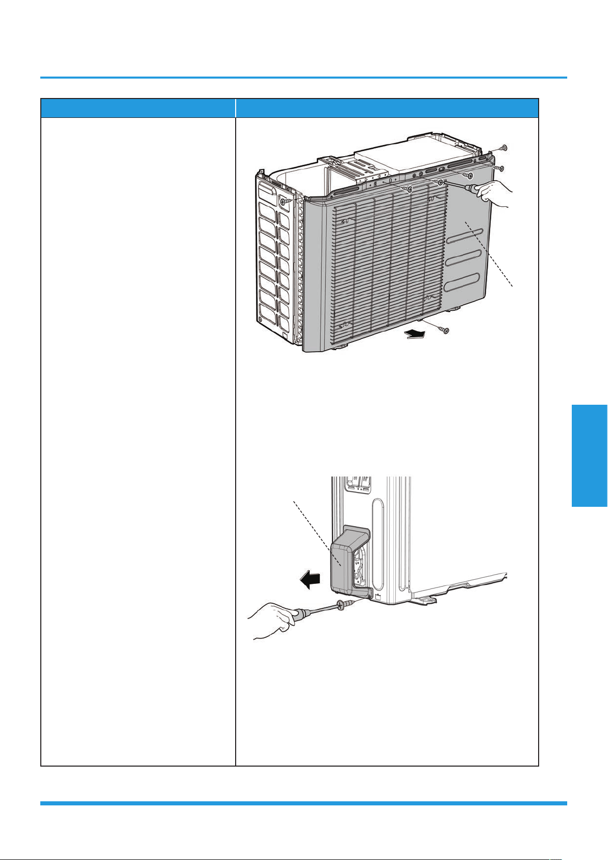
4) Remove the screws of the front panel
and then remove the front panel (7
screws) (see CJ_BA30_003).
5) Remove the screws of water collecting
cover (1 screw) (see CJ_BA30_004).
CJ_BA30_003
CJ_BA30_004
Note: This section is for reference only. Actual unit appearance may vary.
Front Panel
Water Collecting Cover
Maintenance and
Disassembly
Page 44
Procedure Illustration
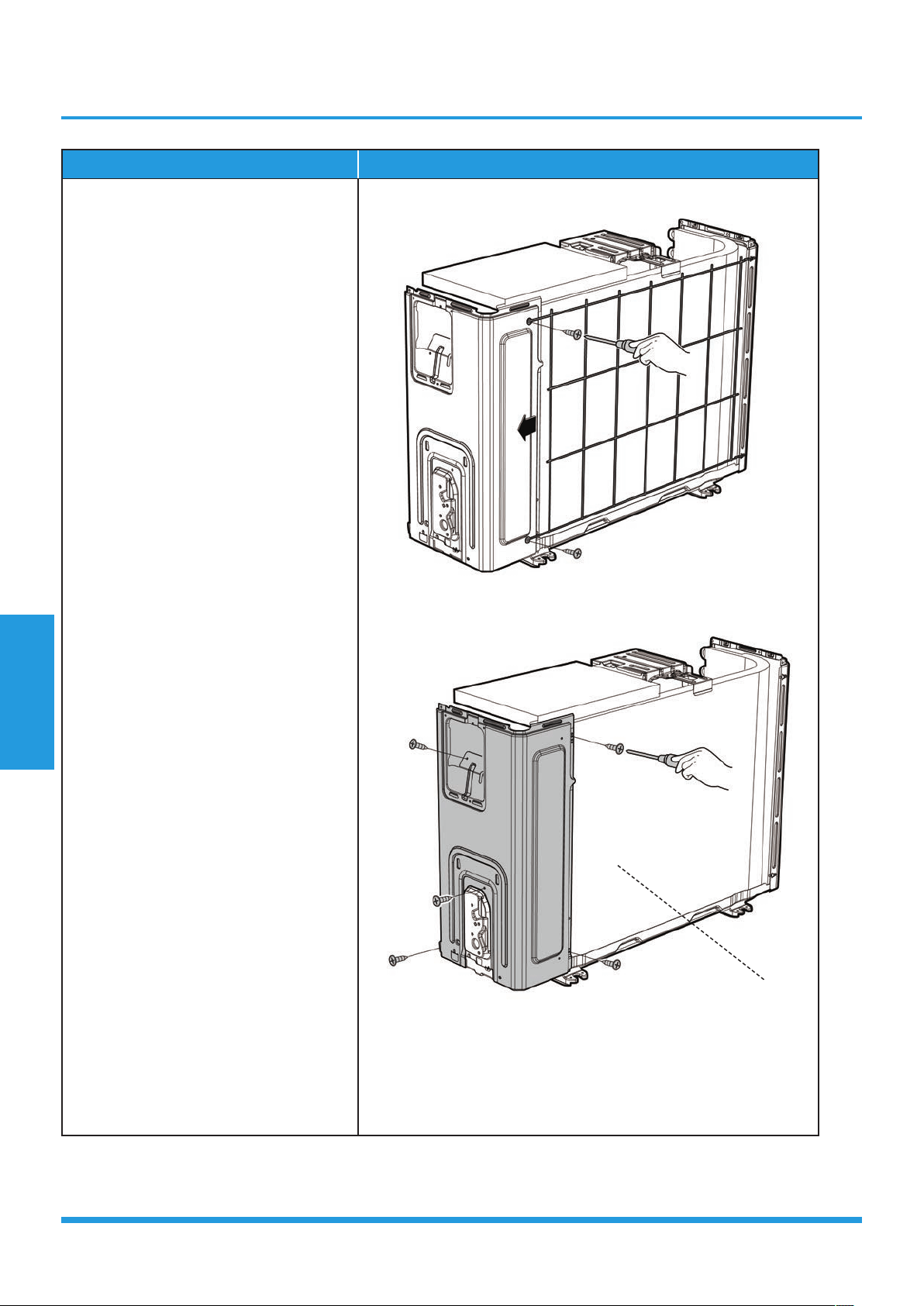
6) Remove the screws of the rear net and
then remove the rear net (2 screws)
(see CJ_BA30_005).
7) Remove the screws of the right panel
and then remove the right panel
(5 screws) (see CJ_BA30_006).
CJ_BA30_005
CJ_BA30_006
Note: This section is for reference only. Actual unit appearance may vary.
Right Panel
Maintenance and
Disassembly
Page 45
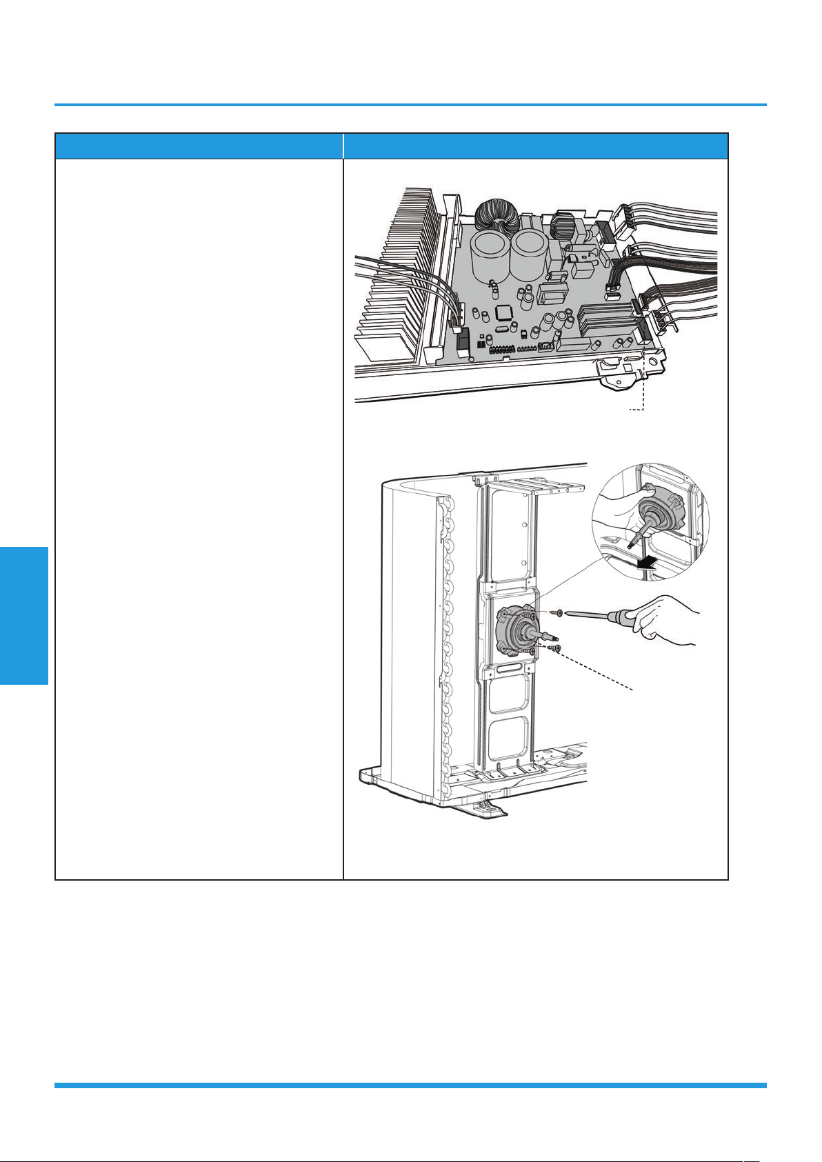
2. Fan disassembly (Antistatic gloves must be worn when you disassemble the electronic box.)
Note: Remove the panel plate and (refer to 1. Panel plate) before disassembling fan.
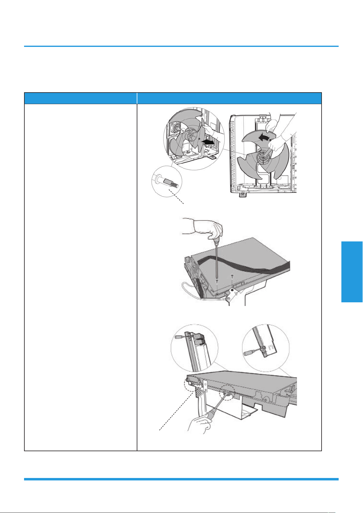
PIAW9165B, PIA12265B:
Procedure Illustration
1) Remove the nut securing the fan
with a spanner (see CJ_ODU_
INV_001).
2) Remove the fan.
3) Remove the screws of the top cover.
(2 screws) (see CJ_ODU_INV_002).
4) Unfix the hooks and then open the
electronic control box cover (4 hooks)
(see CJ_ODU_INV_003).
CJ_ODU_INV_001
CJ_ODU_INV_002
CJ_ODU_INV_003
Note: This section is for reference only. Actual unit appearance may vary.
D-cut
Hook
Maintenance and
Disassembly
Page 46
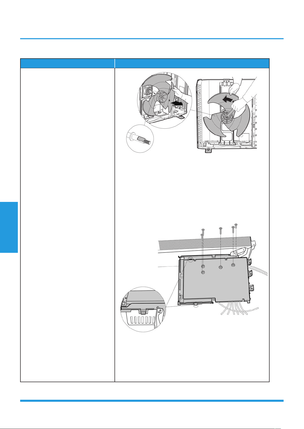
Procedure Illustration
5) Disconnect the connector for fan motor
from the electronic control board (see
CJ_ODU_INV_004).
6) Remove the fixing screws of the fan motor
(4 screws) (see CJ_ODU_INV_005).
7) Remove the fan motor.
CJ_ODU_INV_004
CJ_ODU_INV_005
Note: This section is for reference only. Actual unit appearance may vary.
Fan Motor
Fan Motor

Maintenance and
Disassembly
Page 47
Maintenance and
Disassembly
Page 48
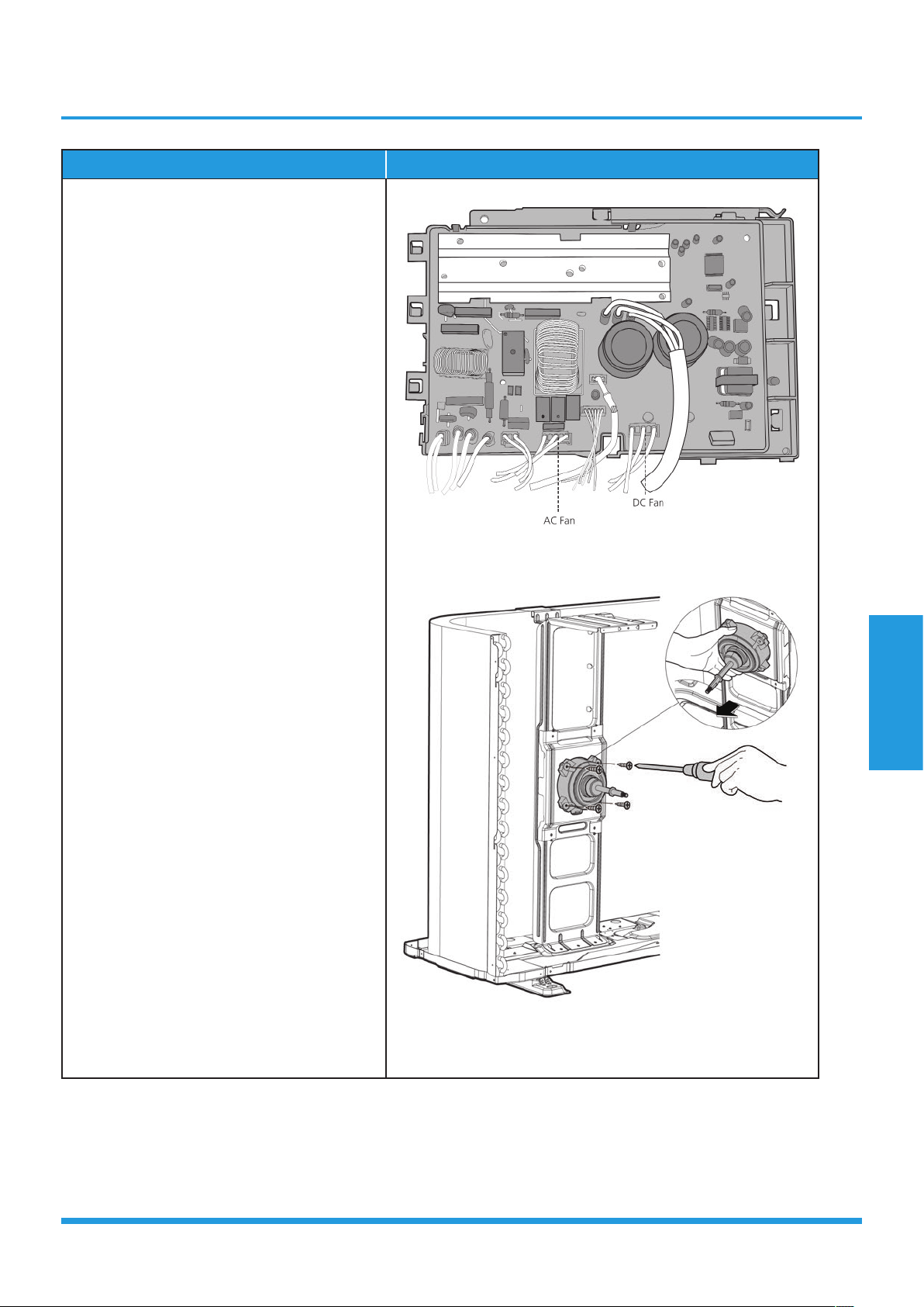
PIA18265B:
Procedure Illustration
1) Remove the nut securing the fan
with a spanner (see CJ_ODU_
INV_010).
2) Remove the fan.
3) Unfix the hooks and then open the
electronic control box cover (4 hooks)
(see CJ_ODU_INV_011).
CJ_ODU_INV_010
CJ_ODU_INV_011
Note: This section is for reference only. Actual unit appearance may vary.
Maintenance and
Disassembly
Page 49
Procedure Illustration
4) Disconnect the connector for fan motor
from the electronic control board (see
CJ_ODU_INV_012).
5) Remove the fixing screws of the fan motor
(4 screws) (see CJ_ODU_INV_013).
6) Remove the fan motor.
CJ_ODU_INV_012
CJ_ODU_INV_013
Note: This section is for reference only. Actual unit appearance may vary.
Maintenance and
Disassembly
Page 50
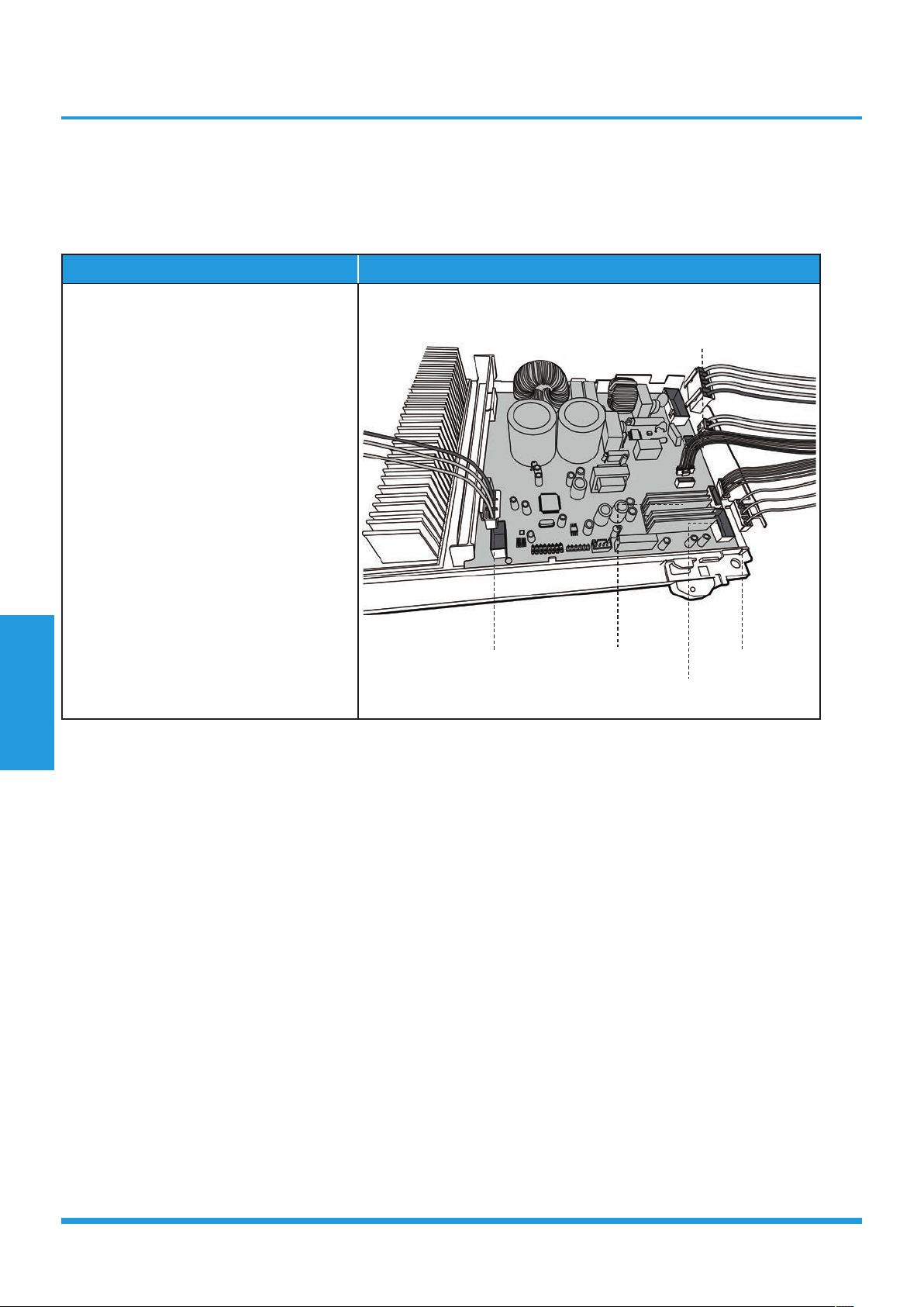
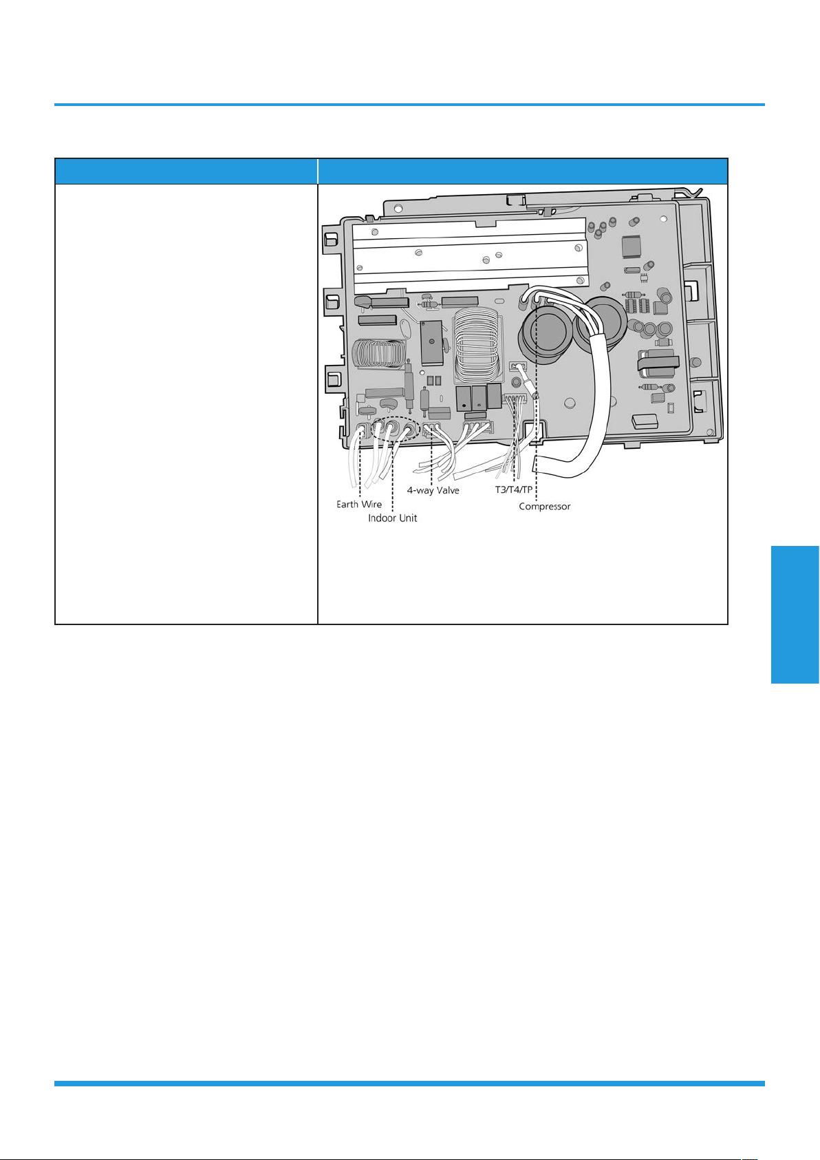
3. Electrical parts (Antistatic gloves must be worn.)
Note: Remove the panel plate and fan assembly (refer to 1. Panel plate and 2. Fan assembly) before
disassembling electrical parts.
PIA12265B, PIA12265B:
Procedure Illustration
1) Remove the connector for the
compressor (see CJ_ODU_INV_014).
2) Pull out the two blue wires connected
with the four way valve (CJ_ODU_
INV_014).
3) Pull out connectors of the condenser
coil temp. sensor(T3),outdoor ambient
temp. sensor(T4) and discharge temp.
sensor(TP) (CJ_ODU_INV_014).
4) Disconnect the electronic expansion
valve wire (CJ_ODU_INV_014).
5) Then remove the electronic control
box (see CJ_ODU_INV_014).
CJ_ODU_INV_014
Note: This section is for reference only. Actual unit appearance may vary.
Compressor
T3, T4, TP
Electronic Expansion Valve
Fan motor
4-Way Valve
Maintenance and
Disassembly
Page 51
PIA18265B;
Procedure Illustration
1) Remove the connector for the
compressor (see CJ_ODU_INV_016).
2) Pull out connectors of the condenser
coil temp. sensor(T3),outdoor ambient
temp. sensor(T4) and discharge temp.
sensor(TP) (see CJ_ODU_INV_016).
3) Disconnect the 4-way valve wire (see
Fig CJ_ODU_INV_016).
4) Disconnect the earth wire (see Fig
CJ_ODU_INV_016).
5) Remove the connector for the indoor
unit (see Fig CJ_ODU_INV_016).
6) Then remove the electronic control box
(see Fig CJ_ODU_INV_016).
CJ_ODU_INV_016
Note: This section is for reference only. Actual unit appearance may vary.
Maintenance and
Disassembly
Page 52
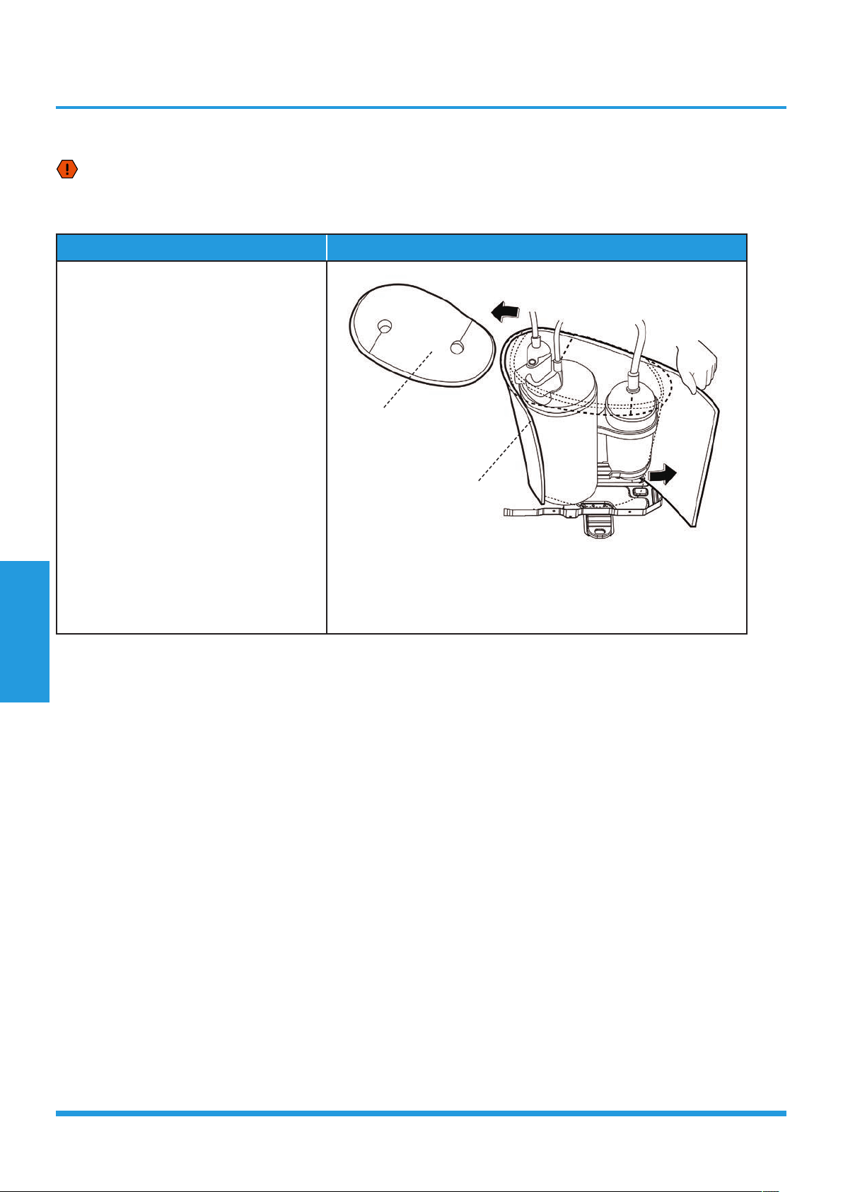
4. Sound blanket
WARNING: Recover refrigerant from the refrigerant circuit before remove the compressor.
Note: Remove the panel plate, electrical parts, and fan assembly (refer to 1. Panel plate, 2. Electrical parts,
and 3. Fan assembly) before disassembling sound blanket.
Procedure Illustration
1) Remove the sound blanket (side and
top) (see CJ_ODU_INV_017).
CJ_ODU_INV_017
Note: This section is for reference only. Actual unit appearance may vary.
Sound Blanket(side)
Sound Blanket(top)
Maintenance and
Disassembly
Page 53
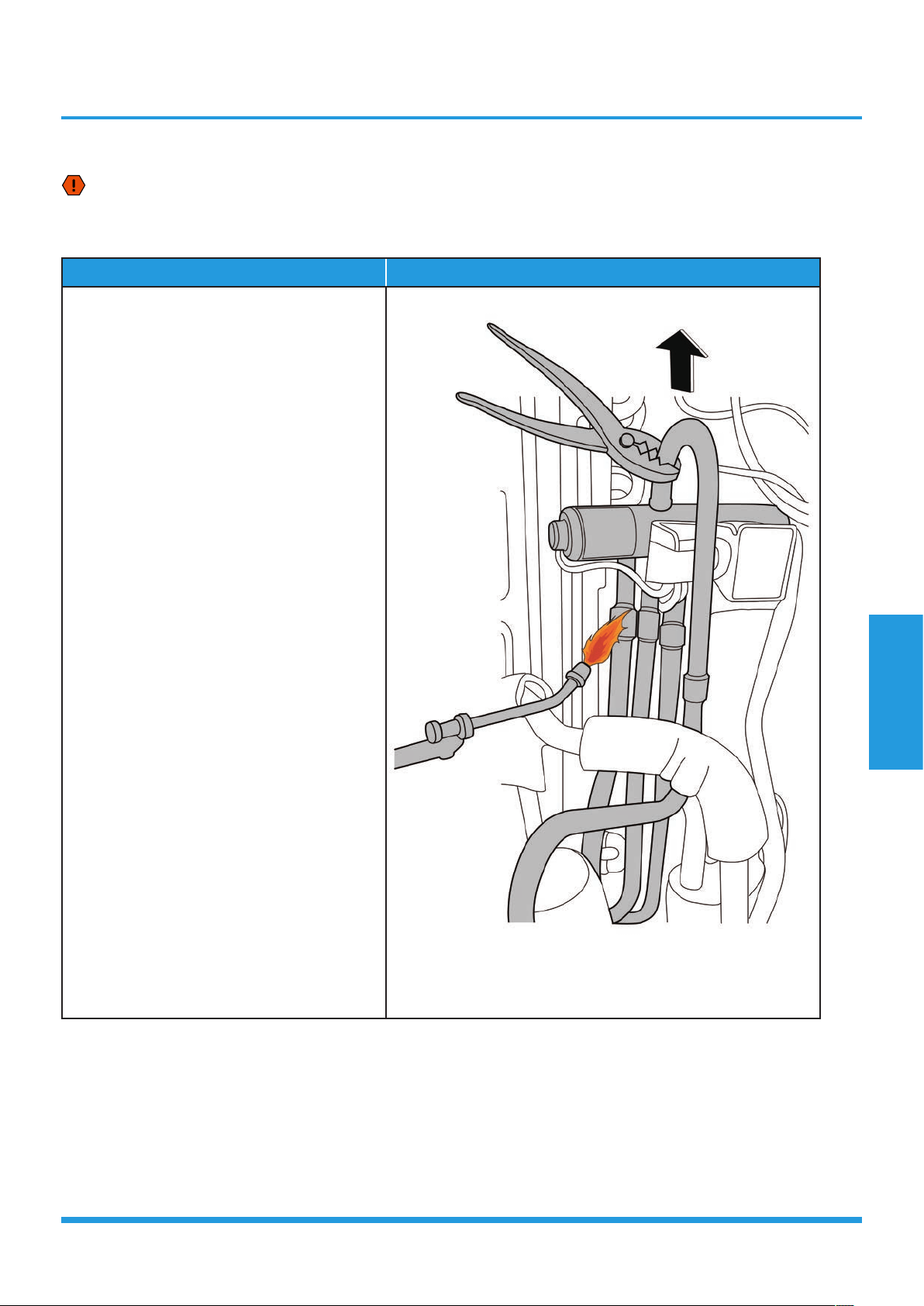
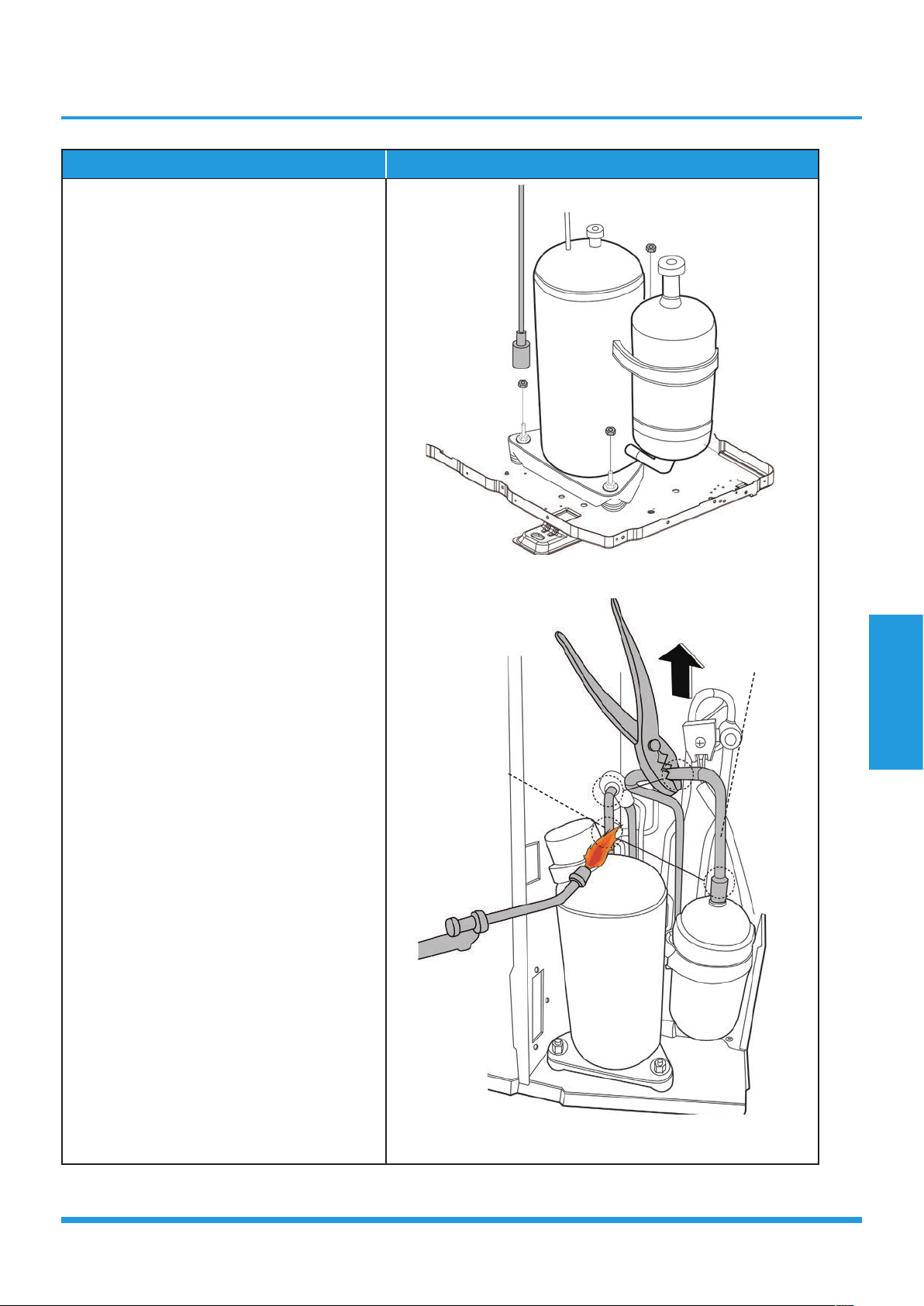
5. Four-way valve
WARNING: Recover refrigerant from the refrigerant circuit before remove the four-way valve.
Note: Remove the panel plate, electrical parts, and fan assembly (refer to 1. Panel plate, 2. Electrical parts,
and 3. Fan assembly) before disassembling four-way valve.
Procedure Illustration
1) Heat up the brazed parts and then detach
the the four-way valve and the pipe (see
CJ_ODU_INV_018).
2) Remove the four-way valve assembly with
pliers.
CJ_ODU_INV_018
Note: This section is for reference only. Actual unit appearance may vary.
Maintenance and
Disassembly
Page 54
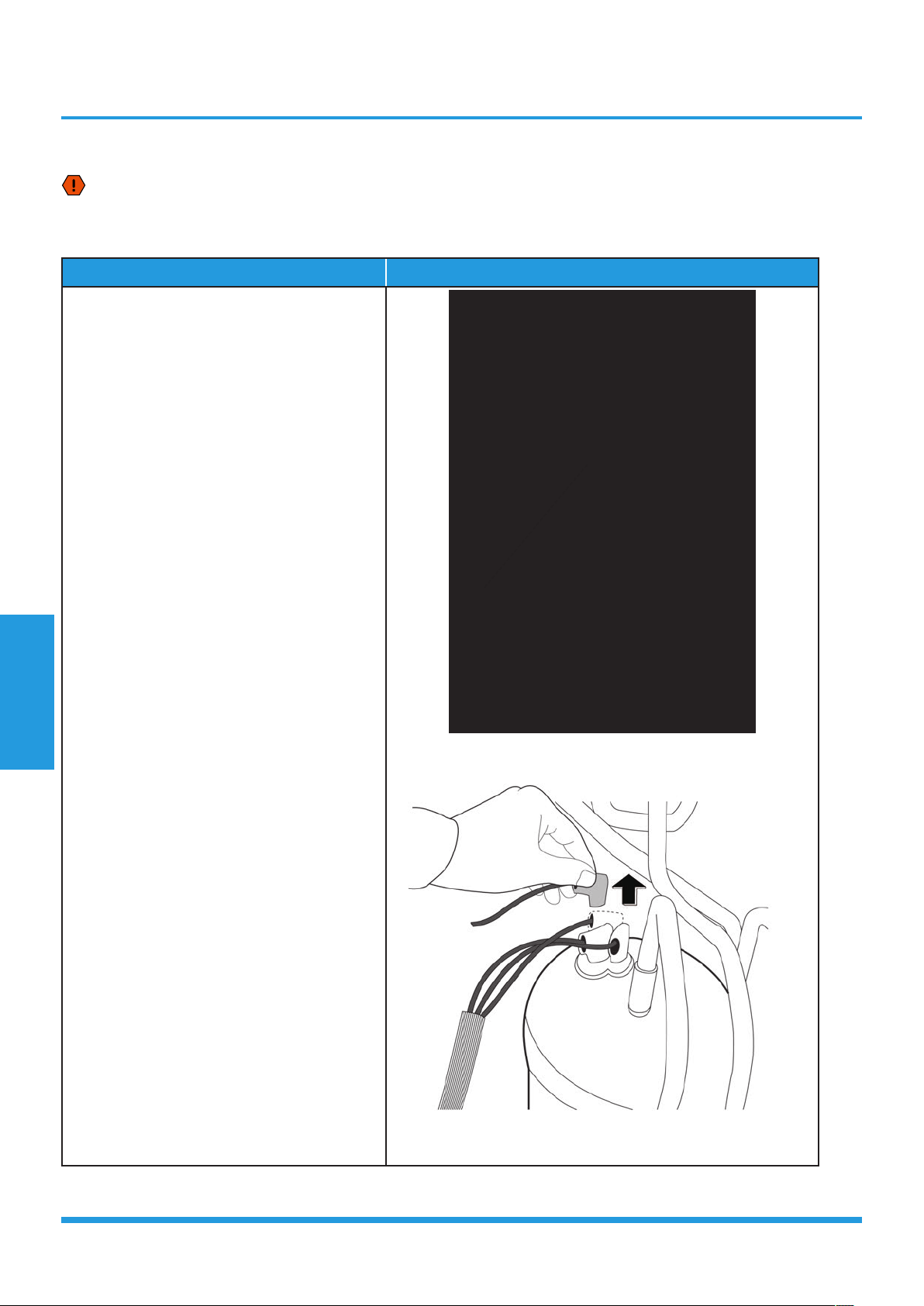
6. Compressor
WARNING: Recover refrigerant from the refrigerant circuit before remove the compressor.
Note: Remove the panel plate, electrical parts, and fan assembly (refer to 1. Panel plate, 2. Electrical parts,
and 3. Fan assembly) before disassembling compressor.
Procedure Illustration
1) Remove the flange nut of terminal cover
and remove the terminal cover (see CJ_
ODU_INV_019).
2) Disconnect the connectors (see CJ_ODU_
INV_020).
CJ_ODU_INV_019
CJ_ODU_INV_020
Note: This section is for reference only. Actual unit appearance may vary.
Terminal Cover
Maintenance and
Disassembly
Page 55
Procedure Illustration
3) Remove the hex nuts and washers securing
the compressor, located on the bottom
plate (see CJ_ODU_INV_021).
4) Heat up the brazed parts and then remove
the the discharge pipe and the suction
pipe (see CJ_ODU_INV_022).
5) Lift the compressor from the base pan
assembly with pliers.
CJ_ODU_INV_021
CJ_ODU_INV_022
Note: This section is for reference only. Actual unit appearance may vary.
Discharge Pipe
Suction Pipe

Contents
1. Safety Caution .....................................................................................................58
2. General Troubleshooting ....................................................................................59
3. Error Diagnosis and Troubleshooting Without Error Code ...............................60
3.1 Remote maintenance ...................................................................................60
3.2 Field maintenance .......................................................................................61
4. Quick Maintenance by Error Code ......................................................................62
5. Troubleshooting by Error Code ...........................................................................67
5.1 Common Check Procedures.........................................................................67
5.2 E0/F4 (EEPROM parameter error) .................................................................69
5.3 E1 (Indoor and outdoor unit communication error) ......................................70
5.4 E2 (Zero-crossing signal detection error) .......................................................72
5.5 E3/F5 (Fan speed is operating outside of the normal range) .........................73
5.6 E4/E5/F1/F2/F3 (Open circuit or short circuit of temperature sensor diagnosis
and solution) ...............................................................................................75
5.7 EC (Refrigerant Leakage Detection diagnosis and solution) ..........................76
5.8 F0(Overload current protection diagnosis and solution) ................................77
5.9 P0(IPM malfunction or IGBT over-strong current protection diagnosis and
solution) ......................................................................................................78
Troubleshooting

Contents
5.10 P1(Over voltage or too low voltage protection diagnosis and solution) .........79
5.11 P2(High temperature protection of IPM module diagnosis and solution) .......80
5.12 P4(Inverter compressor drive error diagnosis and solution) ...........................81
Troubleshooting
Troubleshooting
Page 58
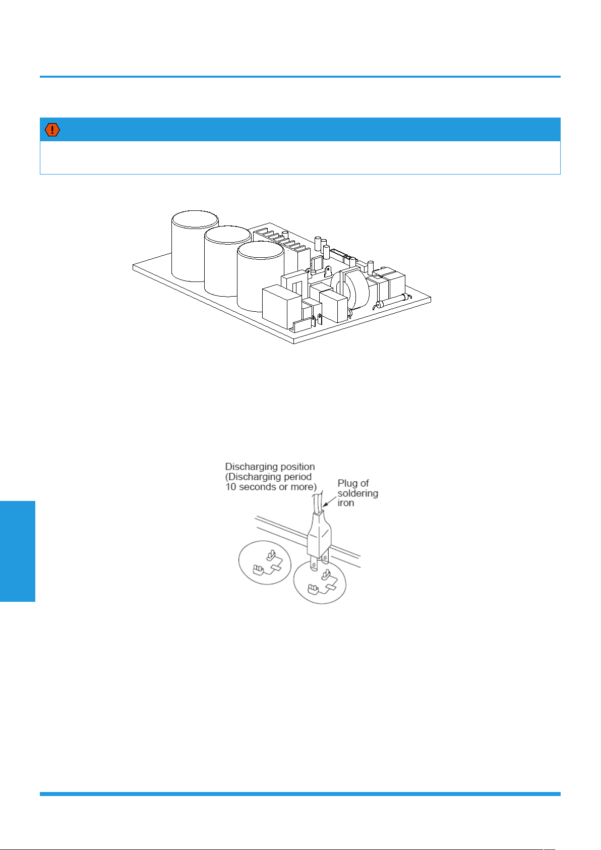
1. Safety Caution
WARNING
Electricity remains in capacitors even when the power supply is off.
Ensure the capacitors are fully discharged before troubleshooting.
For other models, connect discharge resistance (approx.100Ω 40W) or a soldering iron plug between the positive and
negative terminals of the electrolytic capacitor. The terminals are located on the bottom surface of the outdoor PCB.
Note: This picture is for reference only. Actual appearances may vary.
Troubleshooting
Page 59
2. General Troubleshooting
2.1 Error Display (Indoor Unit)
When the indoor unit encounters a recognized error, the indicator light will flash in a corresponding series, the timer
display may turn on or begin flashing, and an error code will be displayed. These error codes are described in the
following table:
Operation
Lamp
Timer
Lamp
Display Error Information Solution
1 times
OFF E0
Indoor unit EEPROM parameter error Page 69
2 times
OFF E1
Indoor / outdoor units communication error Page 70
3 times
OFF E2
Zero-crossing signal detection error (only for PIAW9164A,
PIA12264A)
Page 72
4 times
OFF E3
The indoor fan speed is operating outside of the normal range Page 73
5 times
OFF E4
Indoor room temperature sensor T1 is in open circuit or has
short circuited
Page 75
6 times
OFF E5
Evaporator coil temperature sensor T2 is in open circuit or
has short circuited
Page 75
7 times
OFF EC
Refrigerant leak detected Page 76
1 times
ON F0
Overload current protection Page 77
2 times
ON F1
Outdoor ambient temperature sensor T4 open circuit or
short circuit
Page 75
3 times
ON F2
Condenser coil temperature sensor T3 is in open circuit or
has short circuited
Page 75
4 times
ON F3
Compressor discharge temperature sensor TP open circuit
or short circuit
Page 75
5 times
ON F4
Outdoor unit EEPROM parameter error Page 69
6 times
ON F5
The outdoor fan speed is operating outside of the normal range Page 73
1 times
FLASH p0
IPM malfunction or IGBT over-strong current protection Page 78
2 times
FLASH p1
Over voltage or over low voltage protection Page 79
3 times
FLASH p2
High temperature protection of IPM module Page 80
4 times
FLASH P3*
Outdoor ambient temperature too low. Page --
5 times
FLASH p4
Inverter compressor drive error Page 81
*P3
1) In heating mode, when the outdoor temperature is lower than -25℃ for 1 hour, the indoor unit display error code P3.
2) If the outdoor temperature is higher than -22℃ for 10 minutes and compressor stop for 1 hour or outdoor
temperature is higher than -5℃ for 10 minutes, then the unit will return to work
For other errors:
The display board may show a garbled code or a code undefined by the service manual. Ensure that this code is not a
temperature reading.
Troubleshooting:
Test the unit using the remote control. If the unit does not respond to the remote, the indoor PCB requires replacement.
If the unit responds, the display board requires replacement.
Troubleshooting
Page 60
3. Error Diagnosis and Troubleshooting Without Error Code
WARNING
Be sure to turn off unit before any maintenance to prevent damage or injury.
3.1 Remote maintenance
SUGGESTION: When troubles occur, please check the following points with customers before field maintenance.
NO. Problem Solution
1 Unit will not start Page 63-64
2 The power switch is on but fans will not start Page 63-64
3 The temperature on the display board cannot be set Page 63-64
4 Unit is on but the wind is not cold(hot) Page 63-64
5 Unit runs, but shortly stops Page 63-64
6 The unit starts up and stops frequently Page 63-64
7 Unit runs continuously but insufficient cooling(heating) Page 63-64
8 Cool can not change to heat Page 63-64
9 Unit is noisy Page 63-64

Troubleshooting
Page 61
3.2 Field maintenance
NO. Problem Solution
1 Unit will not start Page 65-66
2 Compressor will not start but fans run Page 65-66
3 Compressor and condenser (outdoor) fan will not start Page 65-66
4 Evaporator (indoor) fan will not start Page 65-66
5 Condenser (Outdoor) fan will not start Page 65-66
6 Unit runs, but shortly stops Page 65-66
7 Compressor short-cycles due to overload Page 65-66
8 High discharge pressure Page 65-66
9 Low discharge pressure Page 65-66
10 High suction pressure Page 65-66
11 Low suction pressure Page 65-66
12 Unit runs continuously but insufficient cooling Page 65-66
13 Too cool Page 65-66
14 Compressor is noisy Page 65-66
15 Horizontal louver can not revolve Page 65-66
Troubleshooting
Page 62
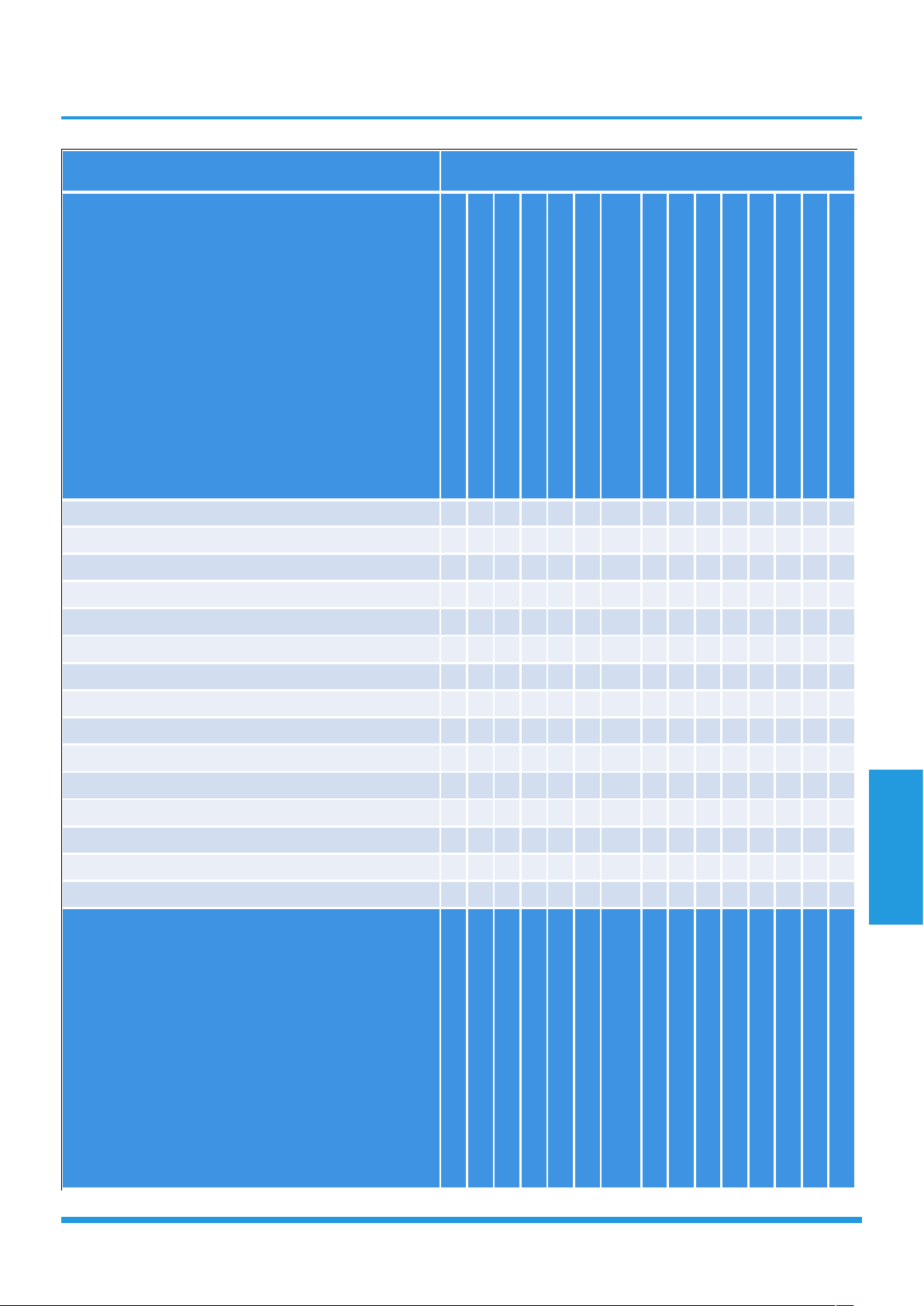
4. Quick Maintenance by Error Code
If you do not have the time to test whether specific parts are faulty, you can directly change the required parts according
the error code.
You can find the parts to replace by error code in the following table.
Part requiring
replacement
Error Code
E0 E1 E2 E3 E4 E5 EC F0 F1
Indoor PCB
x x
Outdoor PCB x x x x x x
Reactor x x x x x x x x
Indoor fan motor x x x x x x x x
Outdoor fan motor x x x X x x x x x
Temperature sensor x x x x x
T2 Sensor x x x x x x x x
Additional refrigerant x x x x x x x x x
Compressor x x x x x x x x
IPM board x x x x x x x x x
Outdoor unit x x x x x x x x
Display board x x x x x x x
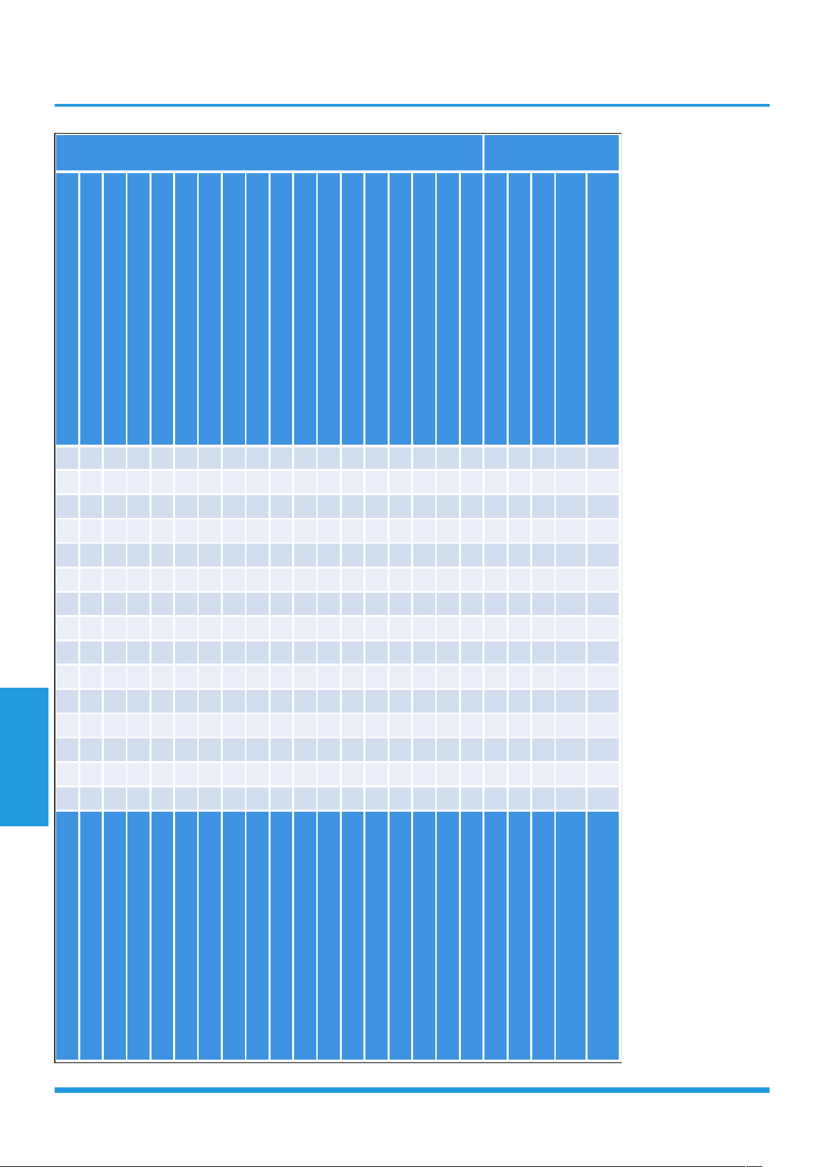
Part requiring replacement
Error Code
F2 F3 F4 F5 P0 P1 P2 P4
Indoor PCB
x x x x x x x x
Outdoor PCB
Reactor x x x x x x x
Indoor fan motor x x x x x x x x
Outdoor fan motor x x x x x x x
Temperature sensor x x x X x x
T2 Sensor x x x x x x x x
Additional refrigerant x x x x x x x x
Compressor x x x x x x
IPM board x x x x x
Outdoor unit x x x x x x x x

Troubleshooting
Page 63
1.Remote Maintenance
Possible causes of trouble
Power failure
The main power tripped
Loose connections
Faulty transformer
The voltage is too high or too low
The remote control is powered off
Broken remote control
Dirty air filter
Dirty condenser fins
The setting temperature is higher/lower than the
room's(cooling/heating)
The ambient temperature is too high/low when the
mode is cooling/heating
Fan mode
SILENCE function is activated(optional function)
Frosting and defrosting frequently
Unit will not start ☆ ☆
☆
☆
The power switch is on but fans will not start
☆ ☆ ☆
The temperature on the display board cannot be set ☆ ☆
Unit is on but the wind is not cold(hot) ☆ ☆ ☆
Unit runs, but shortly stops ☆ ☆ ☆
The unit starts up and stops frequently ☆ ☆ ☆
Unit runs continuously but insufficient cooling(heating) ☆ ☆ ☆ ☆ ☆
Cool can not change to heat
Unit is noisy
Test method / remedy
Test voltage
Close the power switch
Inspect connections - tighten
Change the transformer
Test voltage
Replace the battery of the remote control
Replace the remote control
Clean or replace
Clean
Adjust the setting temperature
Turn the AC later
Adjust to cool mode
Turn off SILENCE function.
Turn the AC later
Refrigerant Circuit
Electrical Circuit

Troubleshooting
Page 64
Heavy load condition
Loosen hold down bolts and / or screws
Bad airproof
The air inlet or outlet of either unit is blocked
Interference from cell phone towers and remote
boosters
Shipping plates remain attached
☆
☆
☆ ☆ ☆
☆ ☆
Check heat load
Tighten bolts or screws
Close all the windows and doors
Remove the obstacles
Reconnect the power or press ON/OFF
button on remote control to restart
Remove them
Others
Troubleshooting
Page 65
2.Field Maintenance
Possible causes of trouble
Power failure
Blown fuse or varistor
Loose connections
Shorted or broken wires
Safety device opens
Faulty thermostat / room temperature sensor
Wrong setting place of temperature sensor
Faulty transformer
Shorted or open capacitor
Faulty magnetic contactor for compressor
Faulty magnetic contactor for fan
Low voltage
Faulty stepping motor
Shorted or grounded compressor
Shorted or grounded fan motor
Unit will not start ☆ ☆ ☆ ☆ ☆ ☆
Compressor will not start but fans run ☆ ☆ ☆ ☆ ☆
Compressor and condenser (outdoor) fan will not start ☆ ☆ ☆
Evaporator (indoor) fan will not start ☆ ☆ ☆ ☆
Condenser (Outdoor) fan will not start ☆ ☆ ☆ ☆ ☆
Unit runs, but shortly stops ☆ ☆
Compressor short-cycles due to overload ☆ ☆
High discharge pressure
Low discharge pressure
High suction pressure
Low suction pressure
Unit runs continuously but insufficient cooling
Too cool ☆ ☆
Compressor is noisy
Horizontal louver can not revolve ☆ ☆ ☆
Test method / remedy
Test voltage
Inspect fuse type & size
Inspect connections - tighten
Test circuits with tester
Test continuity of safety device
Test continuity of thermostat / sensor & wiring
Place the temperature sensor at the central of
the air inlet grille
Check control circuit with tester
Check capacitor with tester
Test continuity of coil & contacts
Test continuity of coil & contacts
Test voltage
Replace the stepping motor
Check resistance with multimeter
Check resistance with multimeter
Electrical Circuit
Troubleshooting
Page 66
Compressor stuck
Shortage of refrigerant
Restricted liquid line
Dirty air filter
Dirty evaporator coil
Insufficient air through evaporator coil
Overcharge of refrigerant
Dirty or partially blocked condenser
Air or incompressible gas in refrigerant cycle
Short cycling of condensing air
High temperature condensing medium
Insufficient condensing medium
Broken compressor internal parts
Inefficient compressor
Expansion valve obstructed
Expansion valve or capillary tube closed completely
Leaking power element on expansion valve
Poor installation of feeler bulb
Heavy load condition
Loosen hold down bolts and / or screws
Shipping plates remain attached
Poor choices of capacity
Contact of piping with other piping or external plate
☆
☆ ☆ ☆ ☆ ☆ ☆
☆ ☆ ☆
☆ ☆ ☆ ☆ ☆ ☆
☆ ☆
☆ ☆ ☆ ☆
☆ ☆ ☆ ☆ ☆ ☆ ☆ ☆
☆ ☆ ☆ ☆ ☆ ☆ ☆ ☆ ☆ ☆ ☆
☆ ☆ ☆ ☆ ☆
Replace the compressor
Leak test
Replace restricted part
Clean or replace
Clean coil
Check fan
Change charged refrigerant volume
Clean condenser or remove obstacle
Purge, evacuate and recharge
Remove obstruction to air flow
Remove obstruction in air or water flow
Remove obstruction in air or water flow
Replace compressor
Test compressor efficiency
Replace valve
Replace valve
Replace valve
Fix feeler bulb
Check heat load
Tighten bolts or screws
Remove them
Choose AC of lager capacity or add the number
of AC
Rectify piping so as not to contact each other or
with external plate
Refrigerant Circuit
Others
Troubleshooting
Page 67
5. Troubleshooting by Error Code
5.1 Common Check Procedures
5.1.1 Temperature Sensor Check
Disconnect the temperature sensor from PCB, measure the resistance value with a tester.
Temperature Sensors.
Room temp.(T1) sensor,
Indoor coil temp.(T2) sensor,
Outdoor coil temp.(T3) sensor,
Outdoor ambient temp.(T4) sensor,
Compressor discharge temp.(Tp) sensor.
Measure the resistance value of each winding by using the multi-meter.
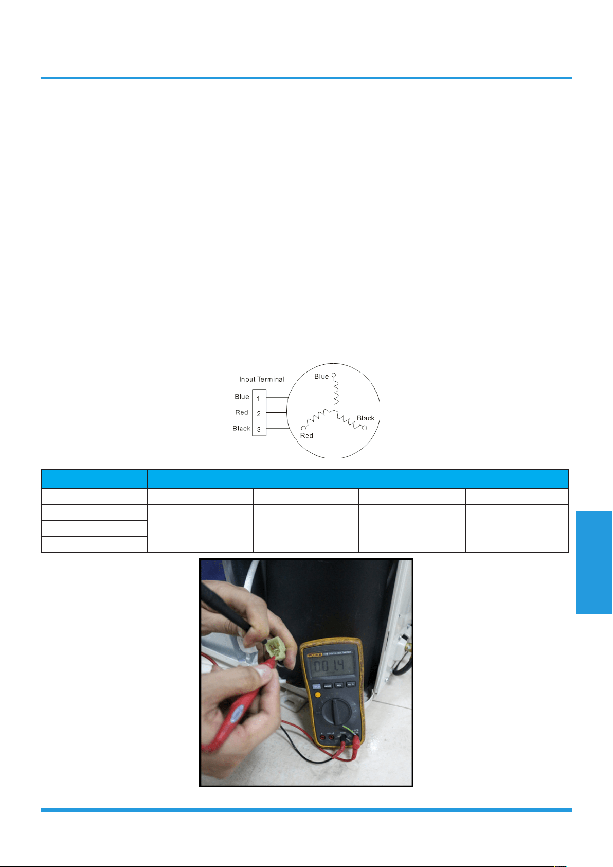
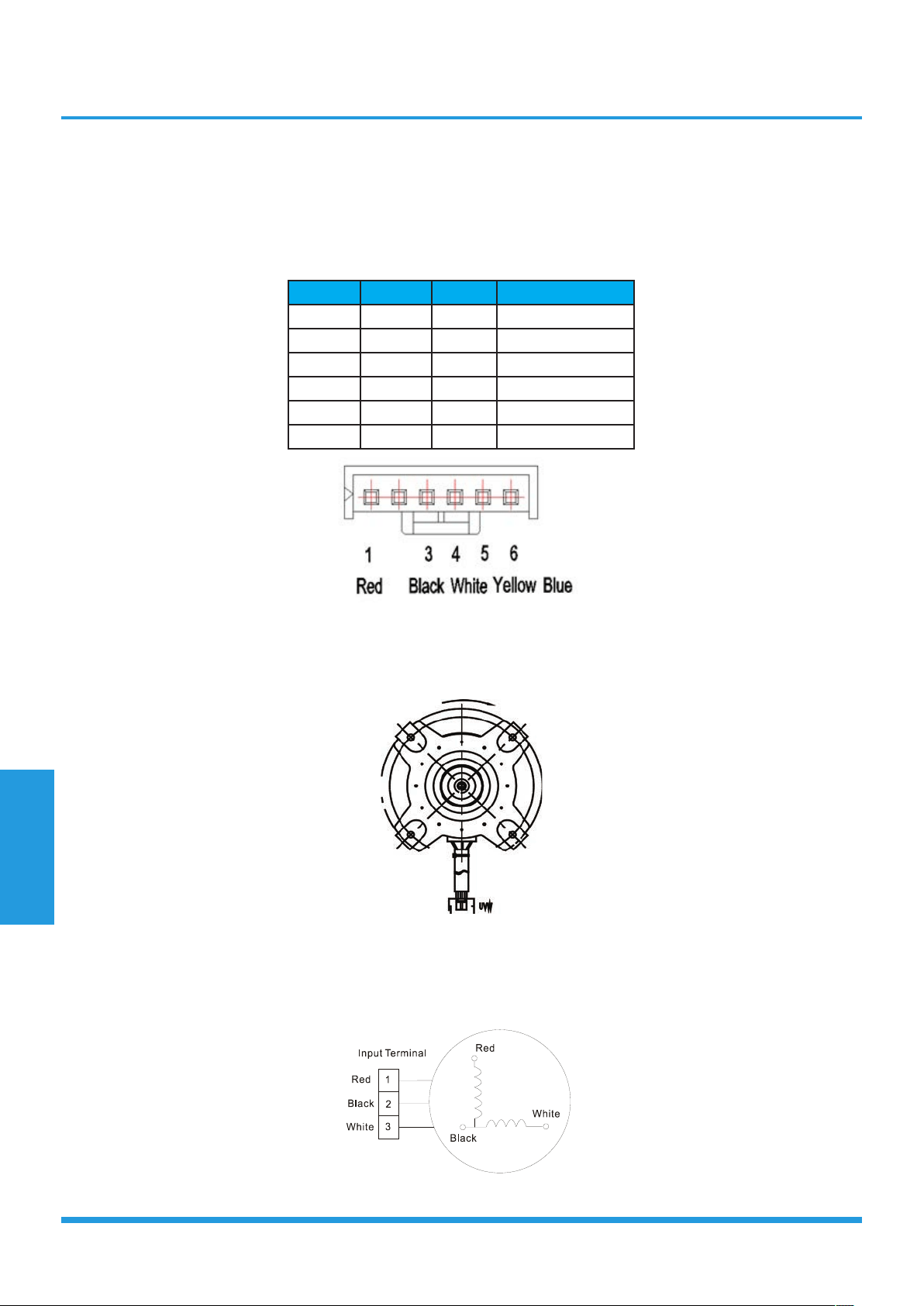
5.1.2 Compressor checking
Measure the resistance value of each winding by using the tester.
Position
Resistance Value
Model ASN98D22UFZ ASK89D29UEZD ASN140D21UFZ ATF235D22UMT
Blue - Red
1.57Ω(20°C/68°F) 1.99Ω(20°C/68°F) 1.28Ω(20°C/68°F) 0.75Ω(20°C/68°F)Blue - Black
Red - Blue
Troubleshooting
Page 68
5.1.3 IPM Continuity Check
Turn off the power, let the large capacity electrolytic capacitors discharge completely, and dismount the IPM. Use a digital
tester to measure the resistance between P and UVWN; UVW and N.
Digital tester
Normal resistance
value
Digital tester
Normal resistance
value
(+)Red (-)Black
∞
(Several MΩ)
(+)Red (-)Black
∞
(Several MΩ)
P
N U
N
U V
V W
W (+)Red
5.1.4 Normal voltage of P and N
Normal voltage of P and N
208-240V(1-phase,3-phase) 380-420V(3-phase)
In standby
around 310VDC around 530VDC
In operation
With passive PFC
module
With partial active
PFC module
With fully active PFC
module
/
>200VDC >310VDC >370VDC >450VDC
Troubleshooting
Page 69
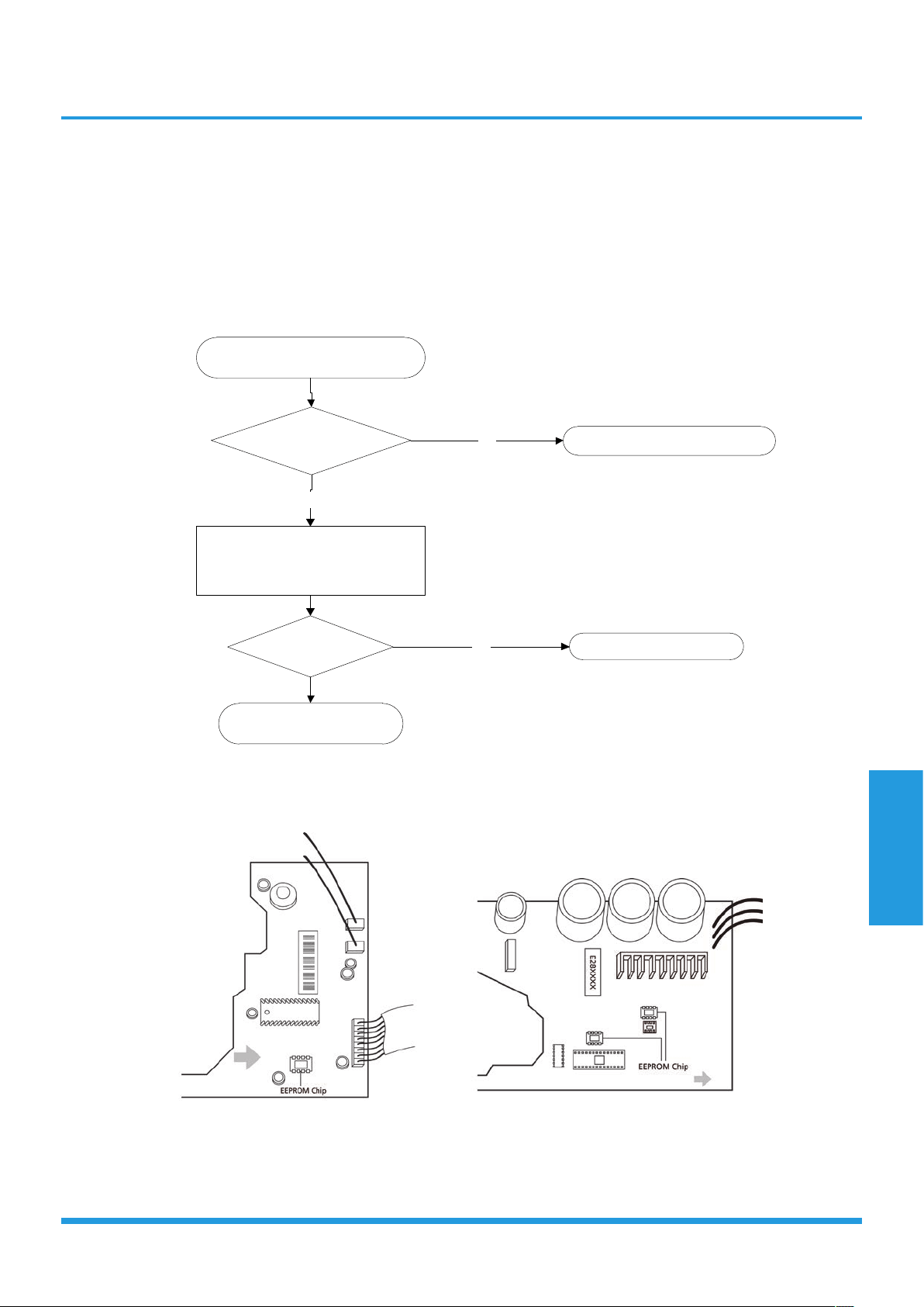
5.2 E0/F4 (EEPROM parameter error)
Description: Indoor or outdoor PCB main chip does not receive feedback from EEPROM chip.
Recommended parts to prepare:
• Indoor PCB
• Outdoor PCB
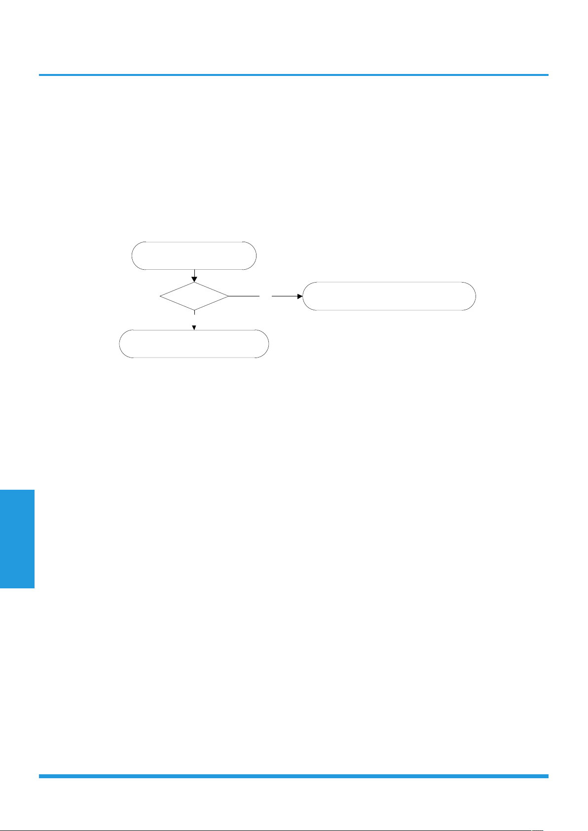
Troubleshooting and repair:
Shut off the power supply and turn it
on 2 minutes later.
Is it still displaying the error
code?
The unit is operating normally.
NO
If the EEPROM chip is welded on main
PCB, replace the main PCB directly.
Otherwise, check if the EEPROM chip
plugged in main PCB well.
YES
Is it plugged well?
Correct the connection.
NO
Replace the indoor/outdoor
main PCB.
Remarks:
The location of the EEPROM chip on the indoor and outdoor PCB is shown in the following two images:
Note: These images are for reference only.
Troubleshooting
Page 70
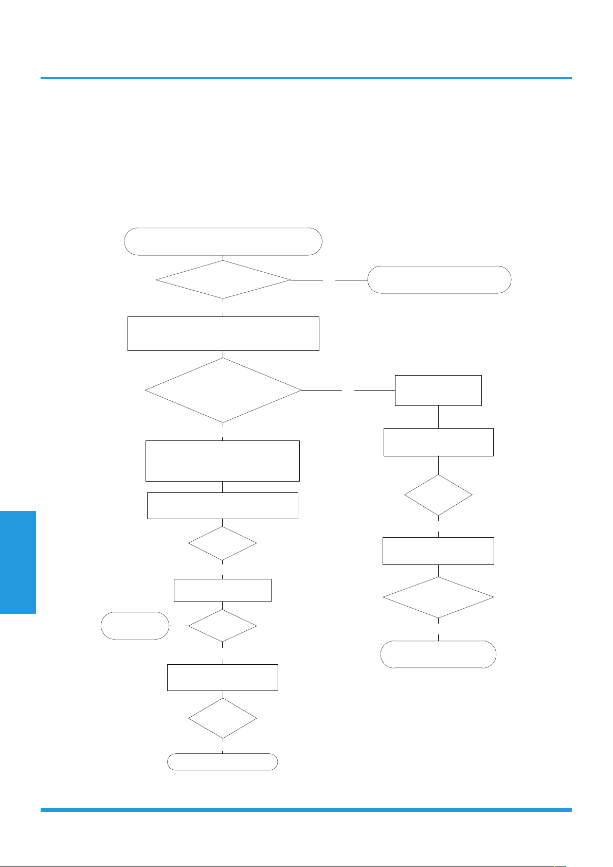
5.3 E1 (Indoor and outdoor unit communication error)
Description: The indoor unit has not received feedback from the outdoor unit for 110 seconds, four consecutive times.
Recommended parts to prepare:
• Indoor PCB
• Outdoor PCB
• Reactor
Troubleshooting and repair:
Power off, then restart the unit after 2 minutes.
Does a problem remain?
The unit is operating normally
NO
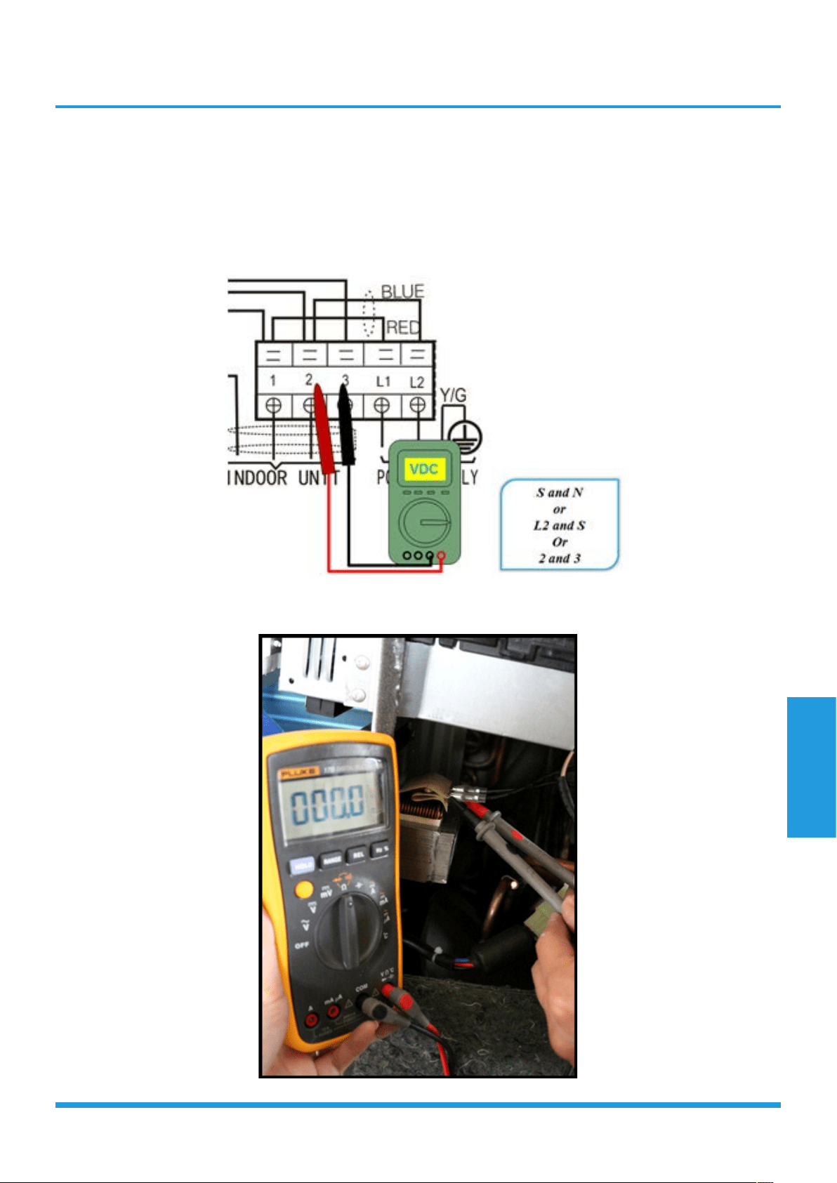
Measure Vs. (Vs is the voltage between S and N of
outdoor unit. Red pan-S, Black pan-N)
YES
Is the voltage moving
alternately between Positive and
negative?
Check the outdoor wiring connection.
Is it normal?
Check the reactor.
YES
Is it normal?
Replace the outdoor PCB.
Power on.
YES
Is the error
resolved?
Replace the indoor PCB.
NO
Replace the
reactor
NO
Check the indoor wiring
connections
Is it normal?
Replace the indoor PCB.
Power on.
YES
Is the error resolved?
Replace the outdoor PCB.
NO
The voltage moves alternately with
positive value.
NO
The voltage is a
certain value
NO
Troubleshooting
Page 71
Remarks:
• Use a multimeter to test the DC voltage between 2 port and 3 port of outdoor unit. The red pin of multimeter
connects with 2 port while the black pin is for 3 port.
• When AC is normal running, the voltage will move alternately between -25V to 25V.
• If the outdoor unit has malfunction, the voltage will move alternately with positive value.
• While if the indoor unit has malfunction, the voltage will be a certain value.
• Use a multimeter to test the resistance of the reactor which does not connect with capacitor.
• The normal value should be around zero ohm. Otherwise, the reactor must have malfunction.
Troubleshooting
Page 72
5.4 E2 (Zero crossing detection error diagnosis and solution) (only for PIAW9164A,
PIA12264A)
Description: When PCB does not receive zero crossing signal feedback for 4 minutes or the zero crossing signal time
interval is abnormal.
Recommended parts to prepare:
• Connection mistake
• PCB faulty
Troubleshooting and repair:
Check the connections and
power supply.
Correct the connections. Turn on the
unit when the power supply is good.
NO
Indoor main PCB is defective. Replace
indoor main PCB.
YES
Is it normal?

Troubleshooting
Page 73
5.5 E3/F5(Fan speed is operating outside of the normal range)
Description: When the indoor fan speed keeps too low (300RPM) for certain time, the unit will stop and the LED will
display the failure(E3). When the outdoor fan speed registers below 200RPM or over 1500RPM for an extended period of
time, the unit will stop and the LED will display the failure(F5).
Recommended parts to prepare:
• Wiring mistake
• Faulty fan assembly
• Faulty fan motor
• Faulty PCB
Troubleshooting and repair:
YES
Power off, then restart the unit after 2 minutes.
Is it within normal parameters?
Replace the fan motor
Does a problem remain?
The unit is operating normallyNO
Shut off the power supply, Rotate
the fan by hand.
YES
Does it turn easily?
Find the cause of the problem and resolve it
NO
Check the wiring of fan motor.
YES
Is it improperly wired?
Ensure proper connections
Measure the voltage for
the fan motor from the PCB.
YES
Replace the indoor/outdoor
PCB
NO
Troubleshooting
Page 74
Index:
1. Indoor or Outdoor DC Fan Motor(control chip is in fan motor)
Power on and when the unit is in standby, measure the voltage of pin1-pin3, pin4-pin3 in fan motor connector. If the
value of the voltage is not in the range showing in below table, the PCB must has problems and need to be replaced.
• DC motor voltage input and output (voltage: 220-240V~):
No. Color Signal Voltage
1 Red Vs/Vm 280V~380V
2 --- --- ---
3 Black GND 0V
4 White Vcc 14-17.5V
5 Yellow Vsp 0~5.6V
6 Blue FG 14-17.5V
2. Outdoor DC Fan Motor (control chip is in outdoor PCB)
Release the UVW connector. Measure the resistance of U-V, U-W, V-W. If the resistance is not equal to each other, the
fan motor must has problems and need to be replaced. otherwise the PCB must has problems and need to be replaced.
3. Indoor AC Fan Motor
Power on and set the unit running in fan mode at high fan speed. After running for 15 seconds, measure the voltage of
pin1 and pin2. If the value of the voltage is less than 100V(208~240V power supply) or 50V(115V power supply), the
PCB must has problems and need to be replaced.
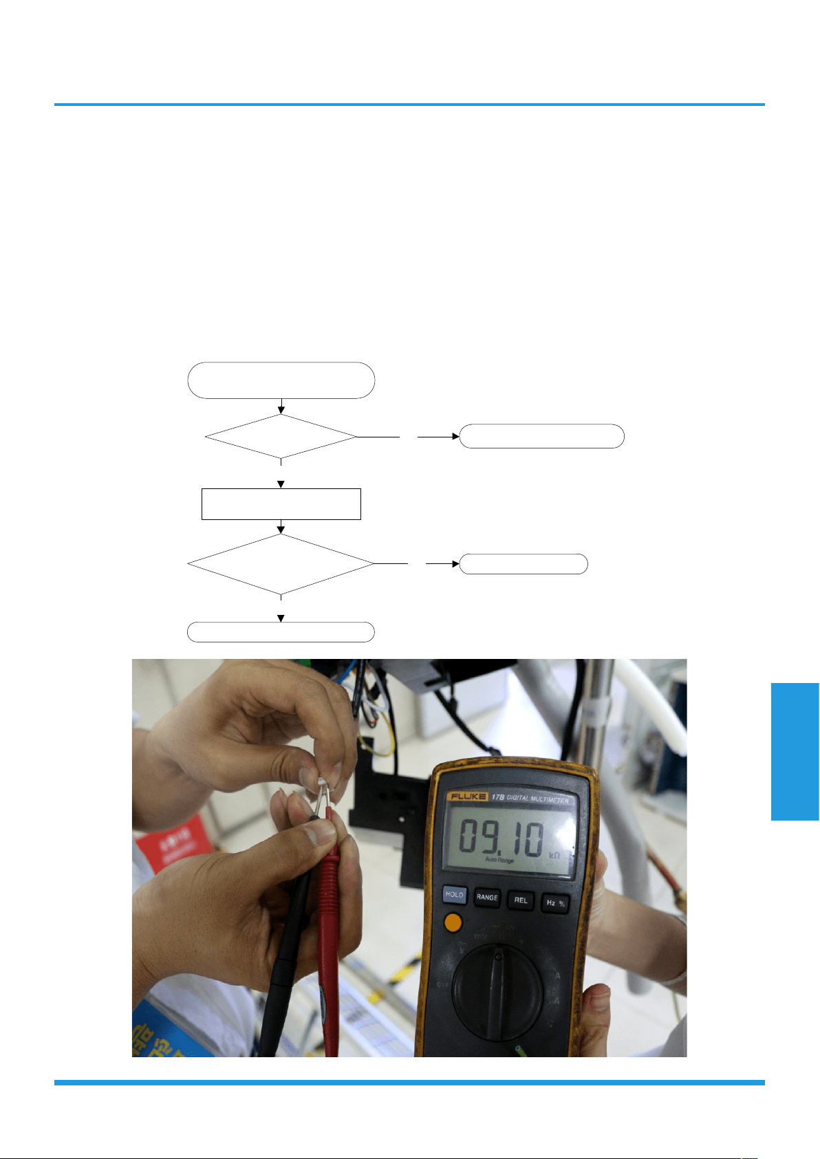
Troubleshooting
Page 75
5.6 E4/E5/F1/F2/F3 (Open circuit or short circuit of temperature sensor diagnosis and
solution)
Description: If the sampling voltage is lower than 0.06V or higher than 4.94V, the LED will display the failure.
Recommended parts to prepare:
• Wiring mistake
• Faulty sensor
• Faulty PCB
Troubleshooting and repair:
Check the connection between
temperature sensor and PCB.
Replace indoor or outdoor PCB
Is it within acceptable
parameters?
Is it properly wired?
Ensure proper connections.
NO
Measure the resistance value
of the sensor.
YES
Replace the Sensor.
NO
YES
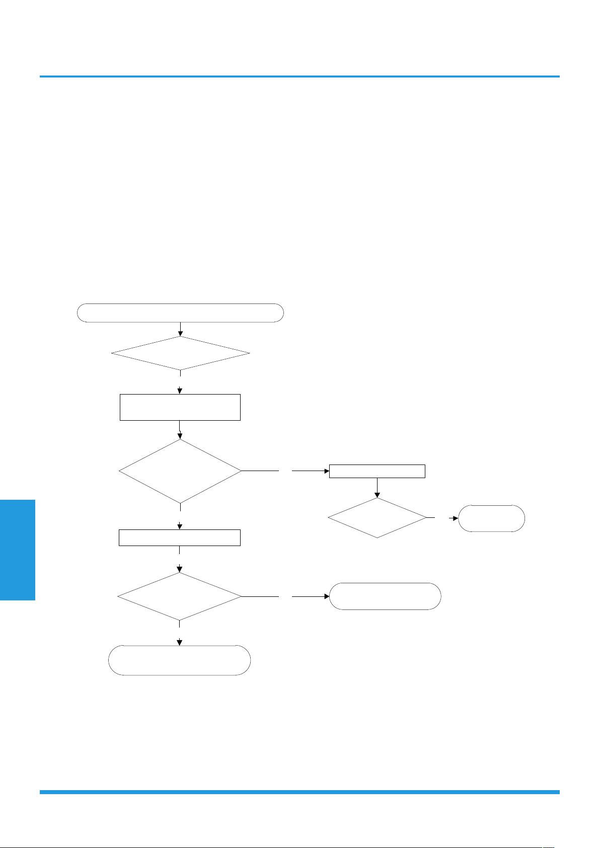
Troubleshooting
Page 76
5.7 EC (Refrigerant Leakage Detection diagnosis and solution)
Description: Define the evaporator coil temp.T2 of the compressor just starts running as Tcool.
In the beginning 8 minutes after the compressor starts up, if T2<Tcool-2°C does not keep continuous 4 seconds and
compressor running frequency higher than 50Hz does not keep continuous 3 minutes, and this situation happens 3
times, the display area will show “EC” and AC will turn off.
Recommended parts to prepare:
• Faulty T2 sensor
• Faulty indoor PCB
• System problems, such as leakage or blockages
Troubleshooting and repair:
Power off, then restart the unit 2 minutes later.
Are any leakages
present?
Check System for blockages and
clear blockages if present.
Does a problem remain?
Put your hands in front of the
indoor air outlet.
YES
Is there cool
air blowing out from
indoor air outlet?
Is it securely
attached?
Replace the
indoor PCB
YES
Check the T2 sensor.
YES
Check system for leakages.
NO
NO
Repair the leakage and
recharge the refrigerant.
YES
NO

Troubleshooting
Page 77
5.8 F0(Overload current protection diagnosis and solution)
Description: An abnormal current rise is detected by checking the specified current detection circuit.
Recommended parts to prepare:
• Power supply problems.
• System blockage
• Faulty PCB
• Wiring mistake
• Compressor malfunction
Troubleshooting and repair:
Check the power supply.
Do any exist?
Are they within acceptable
parameters?
Are they properly connected?
Is it in working order?
Replace the outdoor unit.
Is it in working order?
Check system for blockages.
YES
Stop the unit.
NO
Clear the blockage.
NO
Check the compressor resistance values.
YES
Replace the compressor.
NO
Check the connections and wires.
YES
Ensure proper connections or
replace the wires.
NO
Check the reactor.
YES
YES
Replace outdoor PCB.
NO
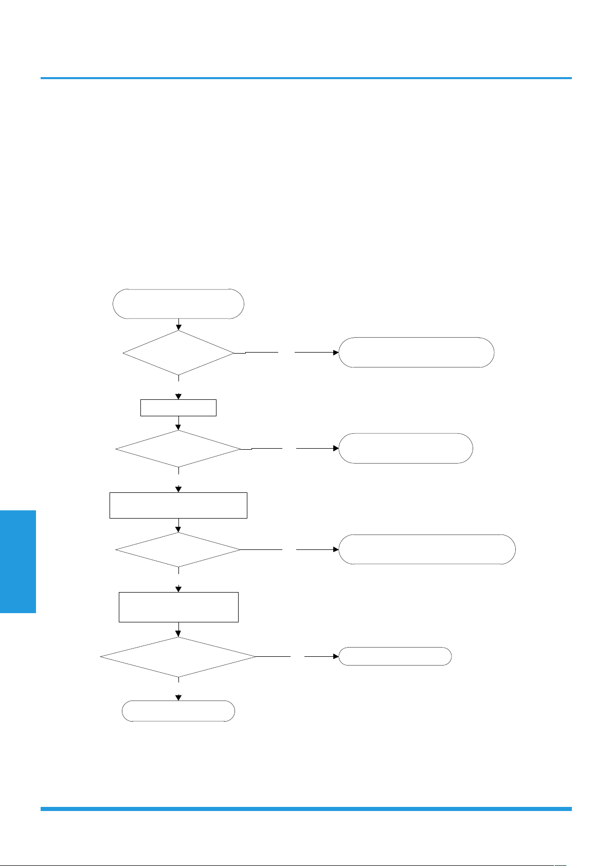
Troubleshooting
Page 78
5.9 P0(IPM malfunction or IGBT over-strong current protection diagnosis and solution)
Description: When the voltage signal the IPM sends to the compressor drive chip is abnormal, the display LED shows
“P0” and the AC turn off.
Recommended parts to prepare:
• Wiring mistake
• IPM malfunction
• Faulty outdoor fan assembly
• Compressor malfunction
• Faulty outdoor PCB
Troubleshooting and repair:
Check the wiring between
PCB and compressor.
Does an error exist?
Ensure proper connections or
replace the wires and connectors.
YES
Check the IPM.
NO
Is it in working order?
Replace the IPM board or
replace the outdoor PCB.
NO
Check the outdoor fan and the
outdoor unit ventilation.
YES
Is it in working order?
Please refer to the solution of the “Fan
Speed is Out of Control”malfunction.
NO
Check the compressor
resistance values.
YES
Are they within
acceptable parameters?
Replace the compressor.
Replace the outdoor PCB.
YES
NO

Troubleshooting
Page 79
5.10 P1(Over voltage or too low voltage protection diagnosis and solution)
Description: Abnormal increases or decreases in voltage are detected by checking the specified voltage detection circuit.
Recommended parts to prepare:
• Power supply issues
• System leakage or blockage
• Faulty PCB
Troubleshooting and repair:
Check the power supply.
Is it in working order?
Turn off the unit.
NO
Check the connections and wires.
YES
Are they in working order?
Ensure proper connections or
replace the wires.
NO
Power on and measure the
voltage between P and N.
YES
While the unit is in standby,
is the voltage between P and N is around
DC 310V, 340V or 380V? When start up
the unit, is it in 220V~400V?
Replace the IPM board.
NO
Check the reactor.
YES
Is it in working order?
Replace outdoor PCB.
NO
Replace the reactor.
YES

Troubleshooting
Page 80
5.11 P2(High temperature protection of IPM module diagnosis and solution)
Description: If the temperature of IPM module is higher than setting value, the LED displays this failure code.
Recommended parts to prepare:
• Faulty PCB
• Connection problems
Troubleshooting and repair:
Check the fastening screws on the
PCB and IPM radiator.
Are they
fixed tightly?
Replace the outdoor
control PCB.
Tighten the screws and apply
silicon grease.
NO
YES
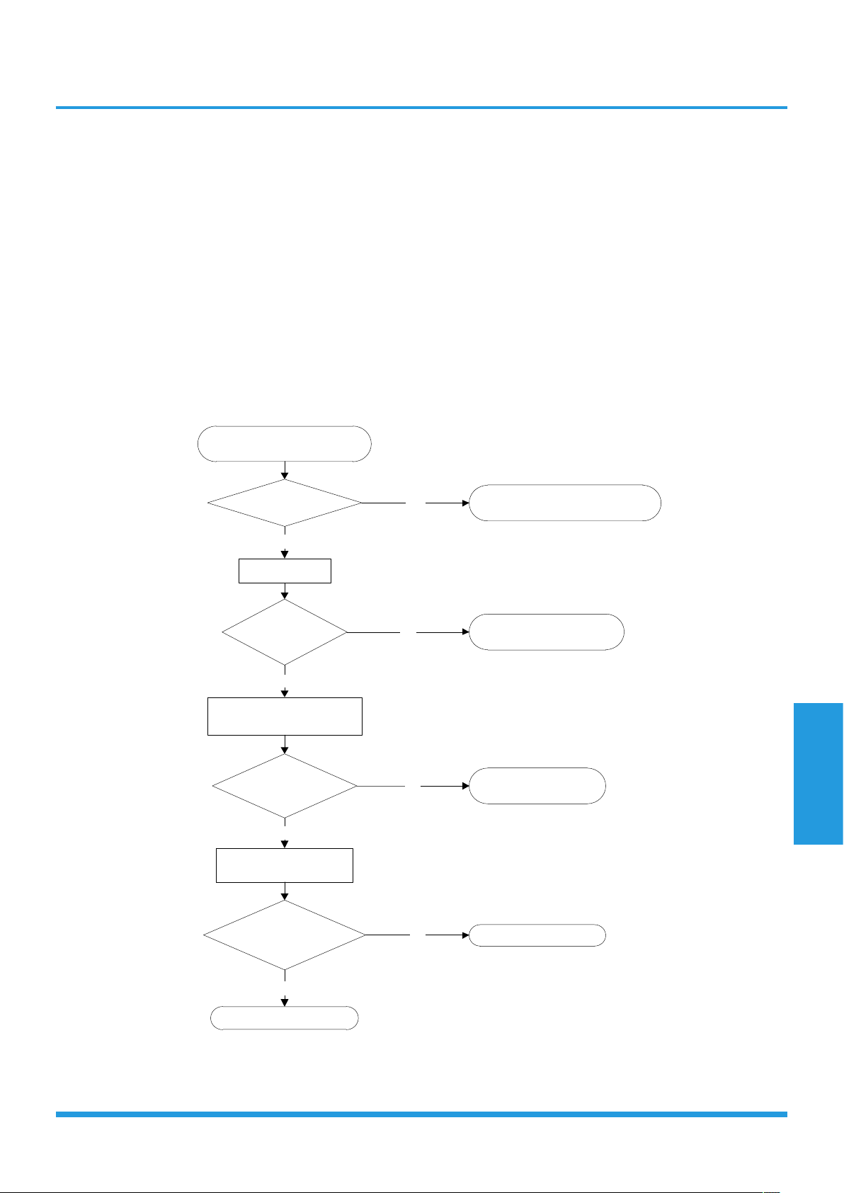
Troubleshooting
Page 81
5.12 P4 (Inverter compressor drive error diagnosis and solution)
Description: An abnormal inverter compressor drive is detected by a special detection circuit, including communication
signal detection, voltage detection, compressor rotation speed signal detection and so on.
Recommended parts to prepare:
• Wiring mistake
• PM malfunction
• Faulty outdoor fan assembly
• Compressor malfunction
• Faulty outdoor PCB
Troubleshooting and repair:
Check the wiring between the
PCB and compressor.
Is it improperly wired?
Ensure proper connections or replace
the wires and connectors.
YES
Check the IPM.
NO
Is it functioning
properly?
Replace the IPM board or
replace the outdoor PCB.
NO
Check the outdoor fan and
the outdoor unit ventilation.
YES
Is it functioning
properly?
Please refer to “Fan
Speed Malfunction”
NO
Check the compressor
resistance values.
YES
Are they within
acceptable parameters?
Replace the compressor.NO
Replace the outdoor PCB.
YES

Contents
i) Temperature Sensor Resistance Value Table for T1, T2, T3, and T4 (°C – K) ....83
ii) Temperature Sensor Resistance Value Table for TP (°C – K)..............................84
iii) △T(°F) ...................................................................................................................85
iV) Pressure On Service Port .....................................................................................86
Appendix

Page 83
Appendix
i) Temperature Sensor Resistance Value Table for T1,T2,T3 and T4 (°C – K)
°C °F K Ohm °C °F K Ohm °C °F K Ohm °C °F K Ohm
-20 -4 115.266 20 68 12.6431 60 140 2.35774 100 212 0.62973
-19 -2 108.146 21 70 12.0561 61 142 2.27249 101 214 0.61148
-18 0 101.517 22 72 11.5 62 144 2.19073 102 216 0.59386
-17 1 96.3423 23 73 10.9731 63 145 2.11241 103 217 0.57683
-16 3 89.5865 24 75 10.4736 64 147 2.03732 104 219 0.56038
-15 5 84.219 25 77 10 65 149 1.96532 105 221 0.54448
-14 7 79.311 26 79 9.55074 66 151 1.89627 106 223 0.52912
-13 9 74.536 27 81 9.12445 67 153 1.83003 107 225 0.51426
-12 10 70.1698 28 82 8.71983 68 154 1.76647 108 226 0.49989
-11 12 66.0898 29 84 8.33566 69 156 1.70547 109 228 0.486
-10 14
62.2756 30 86 7.97078 70 158 1.64691 110 230 0.47256
-9 16 58.7079 31 88 7.62411 71 160 1.59068 111 232 0.45957
-8 18 56.3694 32 90 7.29464 72 162 1.53668 112 234 0.44699
-7 19 52.2438 33 91 6.98142 73 163 1.48481 113 235 0.43482
-6 21 49.3161 34 93 6.68355 74 165 1.43498 114 237 0.42304
-5 23 46.5725 35 95 6.40021 75 167 1.38703 115 239 0.41164
-4 25 44 36 97 6.13059 76 169 1.34105 116 241 0.4006
-3 27 41.5878 37 99 5.87359 77 171 1.29078 117 243 0.38991
-2 28 39.8239 38 100 5.62961 78 172 1.25423 118 244 0.37956
-1 30 37.1988 39 102 5.39689 79 174 1.2133 119 246 0.36954
0 32 35.2024 40 104 5.17519 80 176 1.17393 120 248 0.35982
1 34 33.3269 41
106 4.96392 81 178 1.13604 121 250 0.35042
2 36 31.5635 42 108 4.76253 82 180 1.09958 122 252 0.3413
3 37 29.9058 43 109 4.5705 83 181 1.06448 123 253 0.33246
4 39 28.3459 44 111 4.38736 84 183 1.03069 124 255 0.3239
5 41 26.8778 45 113 4.21263 85 185 0.99815 125 257 0.31559
6 43 25.4954 46 115 4.04589 86 187 0.96681 126 259 0.30754
7 45 24.1932 47 117 3.88673 87 189 0.93662 127 261 0.29974
8 46 22.5662 48 118 3.73476 88 190 0.90753 128 262 0.29216
9 48 21.8094 49 120 3.58962 89 192 0.8795 129 264 0.28482
10 50 20.7184 50 122 3.45097 90 194 0.85248 130 266 0.2777
11 52 19.6891 51 124 3.31847 91 196 0.82643 131 268 0.27078
12 54 18.7177 52 126 3.19183
92 198 0.80132 132 270 0.26408
13 55 17.8005 53 127 3.07075 93 199 0.77709 133 271 0.25757
14 57 16.9341 54 129 2.95896 94 201 0.75373 134 273 0.25125
15 59 16.1156 55 131 2.84421 95 203 0.73119 135 275 0.24512
16 61 15.3418 56 133 2.73823 96 205 0.70944 136 277 0.23916
17 63 14.6181 57 135 2.63682 97 207 0.68844 137 279 0.23338
18 64 13.918 58 136 2.53973 98 208 0.66818 138 280 0.22776
19 66 13.2631 59 138 2.44677 99 210 0.64862 139 282 0.22231

Page 84
Appendix
ii) Temperature Sensor Resistance Value Table for TP (°C – K)
°C °F K Ohm °C °F K Ohm °C °F K Ohm °C °F K Ohm
°C °F K Ohm °C °F K Ohm °C °F K Ohm °C °F K Ohm
-20 -4 542.7 20 68 68.66 60 140 13.59 100 212 3.702
-19 -2 511.9 21 70 65.62 61 142 13.11 101 214 3.595
-18 0 483 22 72 62.73 62 144 12.65 102 216 3.492
-17 1 455.9 23 73 59.98 63 145 12.21 103 217 3.392
-16 3 430.5 24 75 57.37 64 147 11.79 104 219 3.296
-15 5 406.7 25 77 54.89 65 149 11.38 105 221 3.203
-14 7 384.3 26 79 52.53 66 151 10.99 106 223 3.113
-13 9 363.3 27 81 50.28 67 153 10.61 107 225 3.025
-12 10 343.6 28 82 48.14 68 154 10.25 108 226 2.941
-11 12
325.1 29 84 46.11 69 156 9.902 109 228 2.86
-10 14 307.7 30 86 44.17 70 158 9.569 110 230 2.781
-9 16 291.3 31 88 42.33 71 160 9.248 111 232 2.704
-8 18 275.9 32 90 40.57 72 162 8.94 112 234 2.63
-7 19 261.4 33 91 38.89 73 163 8.643 113 235 2.559
-6 21 247.8 34 93 37.3 74 165 8.358 114 237 2.489
-5 23 234.9 35 95 35.78 75 167 8.084 115 239 2.422
-4 25 222.8 36 97 34.32 76 169 7.82 116 241 2.357
-3 27 211.4 37 99 32.94 77 171 7.566 117 243 2.294
-2 28 200.7 38 100 31.62 78 172 7.321 118 244 2.233
-1 30 190.5 39 102 30.36 79 174 7.086 119 246 2.174
0 32 180.9 40
104 29.15 80 176 6.859 120 248 2.117
1 34 171.9 41 106 28 81 178 6.641 121 250 2.061
2 36 163.3 42 108 26.9 82 180 6.43 122 252 2.007
3 37 155.2 43 109 25.86 83 181 6.228 123 253 1.955
4 39 147.6 44 111 24.85 84 183 6.033 124 255 1.905
5 41 140.4 45 113 23.89 85 185 5.844 125 257 1.856
6 43 133.5 46 115 22.89 86 187 5.663 126 259 1.808
7 45 127.1 47 117 22.1 87 189 5.488 127 261 1.762
8 46 121 48 118 21.26 88 190 5.32 128 262 1.717
9 48 115.2 49 120 20.46 89 192 5.157 129 264 1.674
10 50 109.8 50 122 19.69 90 194 5 130 266 1.632
11 52 104.6 51 124 18.96
91 196 4.849
12 54 99.69 52 126 18.26 92 198 4.703
13 55 95.05 53 127 17.58 93 199 4.562
14 57 90.66 54 129 16.94 94 201 4.426
15 59 86.49 55 131 16.32 95 203 4.294
16 61 82.54 56 133 15.73 96 205 4.167
17 63 78.79 57 135 15.16 97 207 4.045
18 64 75.24 58 136 14.62 98 208 3.927
19 66 71.86 59 138 14.09 99 210 3.812

Page 85
Appendix
iii) ∆T(°F)=(9∆T(°C))/5
°C °F °C °F °C °F °C °F °C °F
-5 23 21 69.8 51 123.8 82 179.6 113 235.4
-4 24.8 22 71.6 52 125.6 83 181.4 114 237.2
-3 26.6 23 73.4 53 127.4 84 183.2 115 239
-2 28.4 24 75.2 54 129.2 85 185 116 240.8
-1 30.2 25 77 55 131 86 186.8 117 242.6
0 32 25.5 77.9 56 132.8 87 188.6 118 244.4
0.5 32.9 26 78.8 57 134.6 88 190.4 119 246.2
1 33.8 27 80.6 58 136.4 89 192.2 120 248
1.5 34.7 28 82.4 59 138.2 90 194 121 249.8
2 35.6 29 84.2 60 140 91 195.8 122 251.6
2.5 36.5 30 86 61 141.8 92 197.6 123 253.4
3 37.4 31 87.8 62 143.6 93 199.4 124 255.2
3.5 38.3 32 89.6
63 145.4 94 201.2 125 257
4 39.2 33 91.4 64 147.2 95 203 126 258.8
4.5 40.1 34 93.2 65 149 96 204.8 127 260.6
5 41 35 95 66 150.8 97 206.6 128 262.4
6 42.8 36 96.8 67 152.6 98 208.4 129 264.2
7 44.6 37 98.6 68 154.4 99 210.2 130 266
8 46.4 38 100.4 69 156.2 100 212 131 267.8
9 48.2 39 102.2 70 158 101 213.8 132 269.6
10 50 40 104 71 159.8 102 215.6 133 271.4
11 51.8 41 105.8 72 161.6 103 217.4 134 273.2
12 53.6 42 107.6 73 163.4 104 219.2 135 275
13 55.4 43 109.4 74 165.2 105 221 136 276.8
14 57.2 44 111.2 75 167 106 222.8 137 278.6
15 59 45 113 76 168.8 107 224.6
138 280.4
16 60.8 46 114.8 77 170.6 108 226.4 139 282.2
17 62.6 47 116.6 78 172.4 109 228.2 140 284
18 64.4 48 118.4 79 174.2 110 230 141 285.8
19 66.2 49 120.2 80 176 111 231.8 142 287.6
20 68 50 122 81 177.8 112 233.6 143 289.4
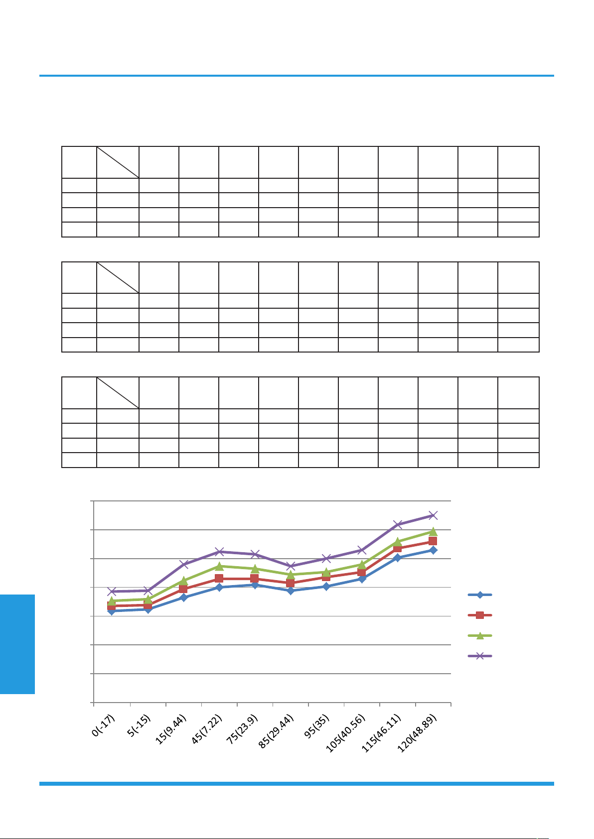
Page 86
Appendix
iV) Pressure On Service Port(R410A)
Cooling chart:
°F(°C)
ODT
IDT
0(-17) 5(-15)
15
(9.44)
45
(7.22)
75
(23.89)
85
(29.44)
95 (35)
105
(40.56)
115
(46.11)
120
(48.89)
BAR 70/59 6.4 6.5 7.3 8.0 8.2 7.8 8.1 8.6 10.1 10.6
BAR 75/63 6.7 6.8 7.9 8.6 8.6 8.3 8.7 9.1 10.7 11.2
BAR 80/67 7.1 7.2 8.5 9.5 9.3 8.9 9.1 9.6 11.2 11.9
BAR 90/73 7.7 7.8 9.6 10.5 10.3 9.5 10.0 10.6 12.4 13.0
°F(°C)
ODT
IDT
0(-17) 5(-15)
15
(9.44)
45
(7.22)
75
(23.89)
85
(29.44)
95 (35)
105
(40.56)
115
(46.11)
120
(48.89)
PSI 70/59 93 94 106 116 119 113 117 125 147 154
PSI 75/63 97 99 115 125 124 120 126 132 155 162
PSI 80/67 103 104 123 138 135 129 132 140 162 173
PSI 90/73 112 113 139 152 149 138 145 154 180 189
°F(°C)
ODT
IDT
0(-17) 5(-15)
15
(9.44)
45
(7.22)
75
(23.89)
85
(29.44)
95 (35)
105
(40.56)
115
(46.11)
120
(48.89)
MPA 70/59 0.64 0.65 0.73 0.8 0.82 0.78 0.81 0.86 1.01 1.06
MPA 75/63 0.67 0.68 0.79 0.86 0.86 0.83 0.87 0.91 1.07 1.12
MPA 80/67 0.71 0.72 0.85 0.95 0.93 0.89 0.91 0.96 1.12 1.19
MPA 90/73 0.77 0.78 0.96 1.05 1.03 0.95 1 1.06 1.24 1.3
0
0.2
0.4
0.6
0.8
1
1.2
1.4
70/59
75/63
80/67
90/73
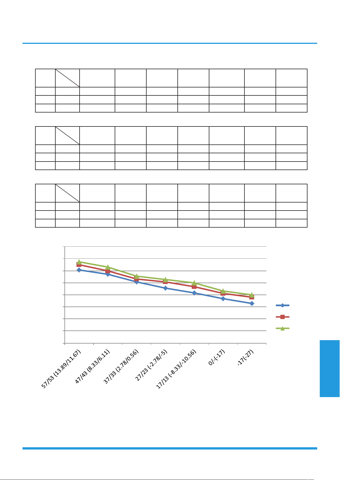
Page 87
Appendix
Heating chart:
°F(°C)
ODT
IDT
57/53
(13.89/11.67)
47/43
(8.33/6.11)
37/33
(2.78/0.56)
27/23
(-2.78/-5)
17/13 (-8.33/-
10.56)
0/-2
(-17/-19)
-17/-18
(-27/-28)
BAR 55 30.3 28.5 25.3 22.8 20.8 18.5 16.5
BAR 65 32.5 30.0 26.6 25.4 23.3 20.5 19.0
BAR 75 33.8 31.5 27.8 26.3 24.9 21.5 20.0
°F(°C)
ODT
IDT
57/53
(13.89/11.67)
47/43
(8.33/6.11)
37/33
(2.78/0.56)
27/23
(-2.78/-5)
17/13 (-8.33/-
10.56)
0/-2
(-17/-19)
-17/-18
(-27/-28)
PSI 55 439 413 367 330 302 268 239
PSI 65 471 435 386 368 339 297 276
PSI 75 489 457 403 381 362 312 290
°F(°C)
ODT
IDT
57/53
(13.89/11.67)
47/43
(8.33/6.11)
37/33
(2.78/0.56)
27/23
(-2.78/-5)
17/13 (-8.33/-
10.56)
0/-2
(-17/-19)
-17/-18
(-27/-28)
MPA 55 3.03 2.85 2.53 2.28 2.08 1.85 1.65
MPA 65 3.25 3.00 2.66 2.54 2.33 2.05 1.90
MPA 75 3.38 3.15 2.78 2.63 2.49 2.15 2.00
0
0.5
1
1.5
2
2.5
3
3.5
4
55
65
75