Use and Care Guide
E L I T E
_®
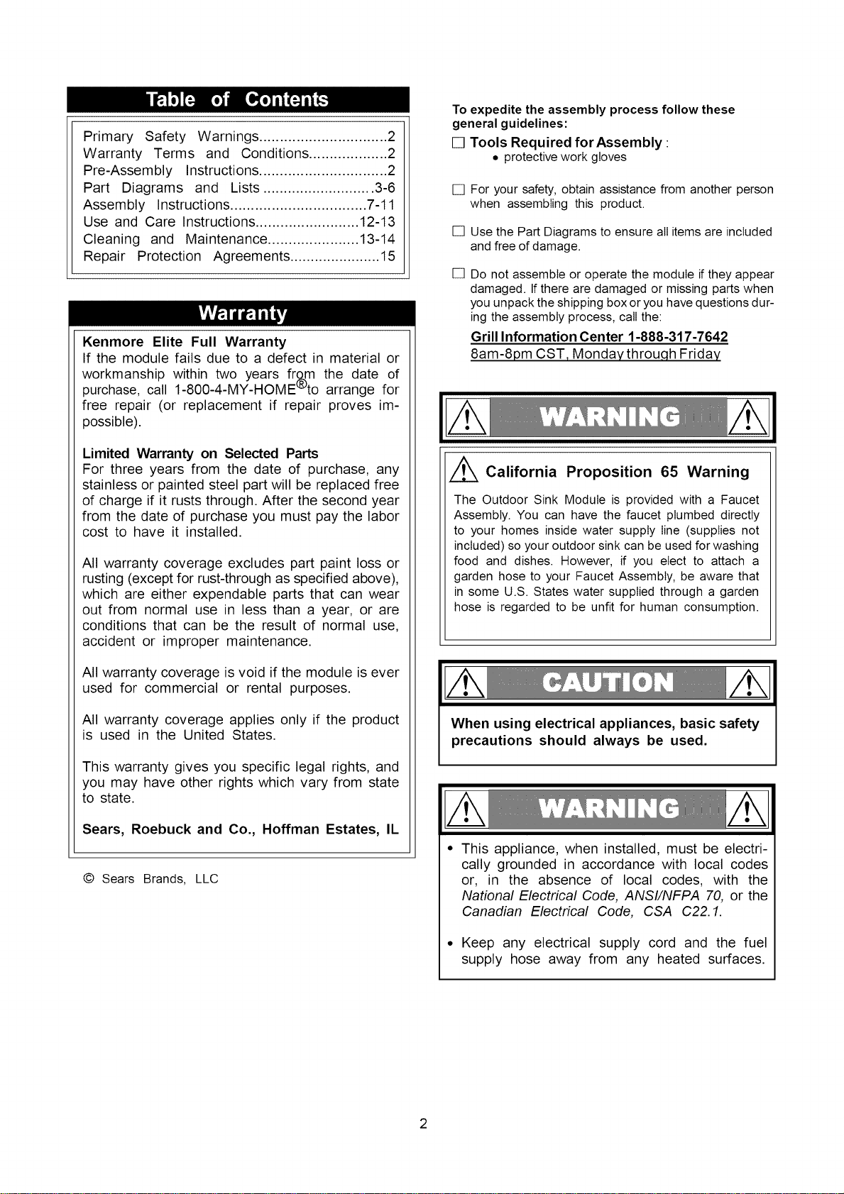
End Panel Module
Model 141.16730900
Serving Cart Module
Model 141.16732900
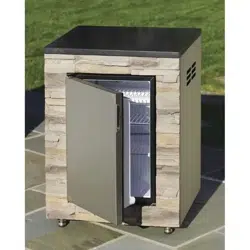
Outdoor Refrigerator Module Outdoor Sink Module
Model 141.16736900 Model 141.16737900
Note: All modules are sold separately.
• Safety
• Assembly
• Use and Care
Call us first if you have any problem with
this product. We can help you with ques-
tions about assembly and operation or if
there are damaged or missing parts when
you unpack this unit from the shipping box.
Please call before contacting your local
retailer.
1-888-317-7642
8am-8pm CST, Monday throu.qh Friday
NOTE TO ASSEMBLER/INSTALLER:
Leave this guide with the consumer.
NOTE TO CONSUMER:
Keep this guide for future reference.
• RECORD YOUR SERIAL #
(see silver CSA/serial label on main bodyof module)
Sears, Roebuck and Co., Hoffman Estates, IL 60179, USA www.sears.com
Guide # P80174008L - Date:2009/01/21
Primary Safety Warnings ............................... 2
Warranty Terms and Conditions ................... 2
Pre-Assembly Instructions ............................... 2
Part Diagrams and Lists ........................... 3-6
Assembly Instructions ................................. 7-11
Use and Care Instructions ......................... 12-13
Cleaning and Maintenance ...................... 13-14
Repair Protection Agreements ...................... 15
Kenmore Elite Full Warranty
If the module fails due to a defect in material or
workmanship within two years from the date of
purchase, call 1-800-4-MY-HOME'to arrange for
free repair (or replacement if repair proves im-
possible).
Limited Warranty on Selected Parts
For three years from the date of purchase, any
stainless or painted steel part will be replaced free
of charge if it rusts through. After the second year
from the date of purchase you must pay the labor
cost to have it installed.
All warranty coverage excludes part paint loss or
rusting (except for rust-through as specified above),
which are either expendable parts that can wear
out from normal use in less than a year, or are
conditions that can be the result of normal use,
accident or improper maintenance.
All warranty coverage is void if the module is ever
used for commercial or rental purposes.
All warranty coverage applies only if the product
is used in the United States.
This warranty gives you specific legal rights, and
you may have other rights which vary from state
to state.
Sears, Roebuck and Co., Hoffman Estates, IL
© Sears Brands, LLC
To expedite the assembly process follow these
general guidelines:
[] Tools Required forAssembly :
• protective work gloves
[]
[]
[]
For your safety, obtain assistance from another person
when assembling this product.
Use the Part Diagrams to ensure all items are included
and free of damage.
Do not assemble or operate the module if they appear
damaged. If there are damaged or missing parts when
you unpack the shipping box or you have questions dur-
ing the assembly process, call the:
Grill Information Center 1-888-317-7642
8am-8pm CST, Monday throuqh Friday
California Proposition 65 Warning
The Outdoor Sink Module is provided with a Faucet
Assembly. You can have the faucet plumbed directly
to your homes inside water supply line (supplies not
included) so your outdoor sink can be used for washing
food and dishes. However, if you elect to attach a
garden hose to your Faucet Assembly, be aware that
in some U.S. States water supplied through a garden
hose is regarded to be unfit for human consumption.
When using electrical appliances, basic safety
precautions should always be used.
This appliance, when installed, must be electri-
cally grounded in accordance with local codes
or, in the absence of local codes, with the
National Electrical Code, ANSI/NFPA 70, or the
Canadian Electrical Code, CSA C22. 1.
• Keep any electrical supply cord and the fuel
supply hose away from any heated surfaces.
5-.
6
-3
" " " -4
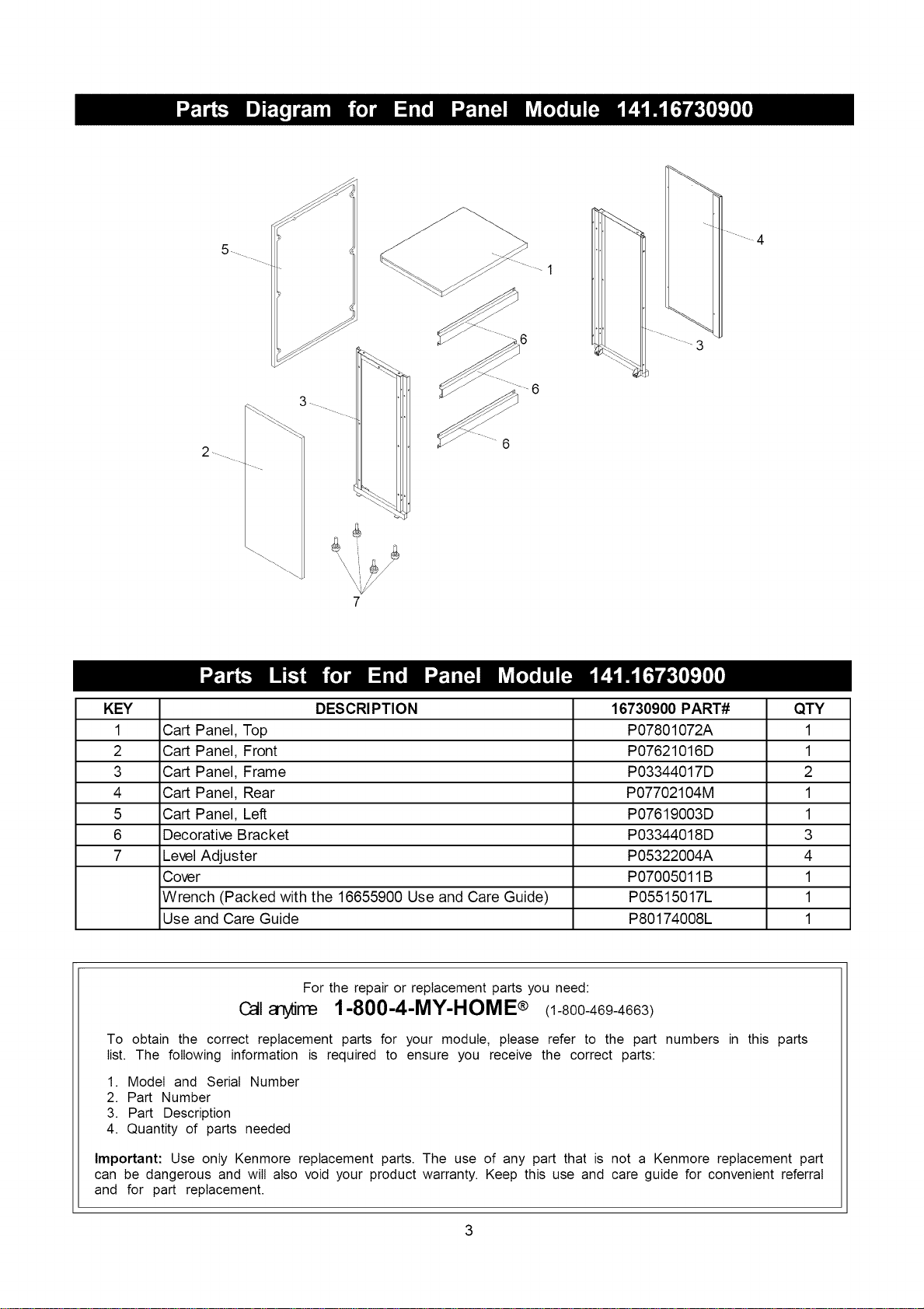
KEY DESCRI PTION 16730900 PART# QTY
1 Cart Panel, Top P07801072A 1
2 Cart Panel, Front P07621016D 1
3 Cart Panel, Frame P03344017D 2
4 Cart Panel, Rear P07702104M 1
5 Cart Panel, Left P07619003D 1
6 Decorative Bracket P03344018D 3
7 Level Adjuster P05322004A 4
Cover P07005011B 1
Wrench (Packed with the 16655900 Use and Care Guide) P05515017L 1
Use and Care Guide P80174008L 1
For the repair or replacement parts you need:
Calla rre 1-800-4-MY-HOME® (1-800-469-4663)
To obtain the correct replacement parts for your module, please refer to the part numbers in this parts
list. The following information is required to ensure you receive the correct parts:
1. Model and Serial Number
2. Part Number
3. Part Description
4. Quantity of parts needed
Important: Use only Kenmore replacement parts. The use of any part that is not a Kenmore replacement part
can be dangerous and will also void your product warranty. Keep this use and care guide for convenient referral
and for part replacement.
13
13a
11
® ........i2 15........._ _9
%'_16 _14a
4
2
_12
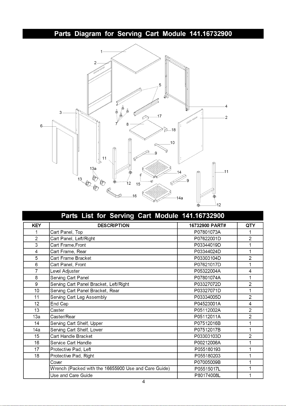
KEY DESCRI PTION 16732900 PART# QTY
1 Cart Panel, Top P07801073A 1
2 Cart Panel, Left/Right P07622001D 2
3 Cart Frame,Front P03344019D 1
4 Cart Frame, Rear P03344024D 1
5 Cart Frame Bracket P03303104D 2
6 Cart Panel, Front P07621017D 1
7 Level Adjuster P05322004A 4
8 Serving Cart Panel P07801074A 1
9 Serving Cart Panel Bracket, Left/Right P03327072D 2
10 Serving Cart Panel Bracket, Rear P03327071D 1
11 Serving Cart Leg Assembly P03334005D 2
12 End Cap P04523001A 4
13 Caster P05112002A 2
13a Caster/Rear P05112011A 2
14 Serving Cart Shelf, Upper P07512016B 1
14a Serving Cart Shelf, Lower P07512017B 1
15 Cart Handle Bracket P03303103D 2
16 Service Cart Handle P00212006A 1
17 Protective Pad, Left P055180193 1
18 Protective Pad, Right P055180203 1
Cover P07005009B 1
Wrench (Packed with the 16655900 Use and Care Guide) P05515017L 1
Use and Care Guide P80174008L 1
4
2 _
4_
\
11
9
6
lO
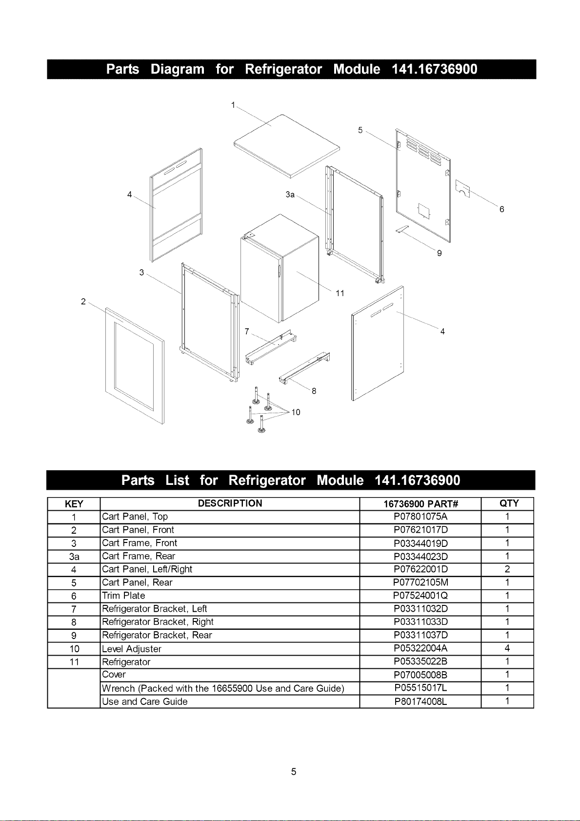
KEY DESCRI PTION 16736900 PART# QTY
1 Cart Panel, Top P07801075A 1
2 Cart Panel, Front P07621017D 1
3 Cart Frame, Front P03344019D 1
3a Cart Frame, Rear P03344023D 1
4 Cart Panel, Left/Right P07622001D 2
5 Cart Panel, Rear P07702105M 1
6 Trim Plate P07524001Q 1
7 Refrigerator Bracket, Left P03311032D 1
8 Refrigerator Bracket, Right P03311033D 1
9 Refrigerator Bracket, Rear P03311037D 1
10 Level Adjuster P05322004A 4
11 Refrigerator P05335022B 1
Cover P07005008B 1
Wrench (Packed with the 16655900 Use and Care Guide) P05515017L 1
Use and Care Guide P80174008L 1
5
2\
8\
4\
12
11\
10\\\
7 \-4
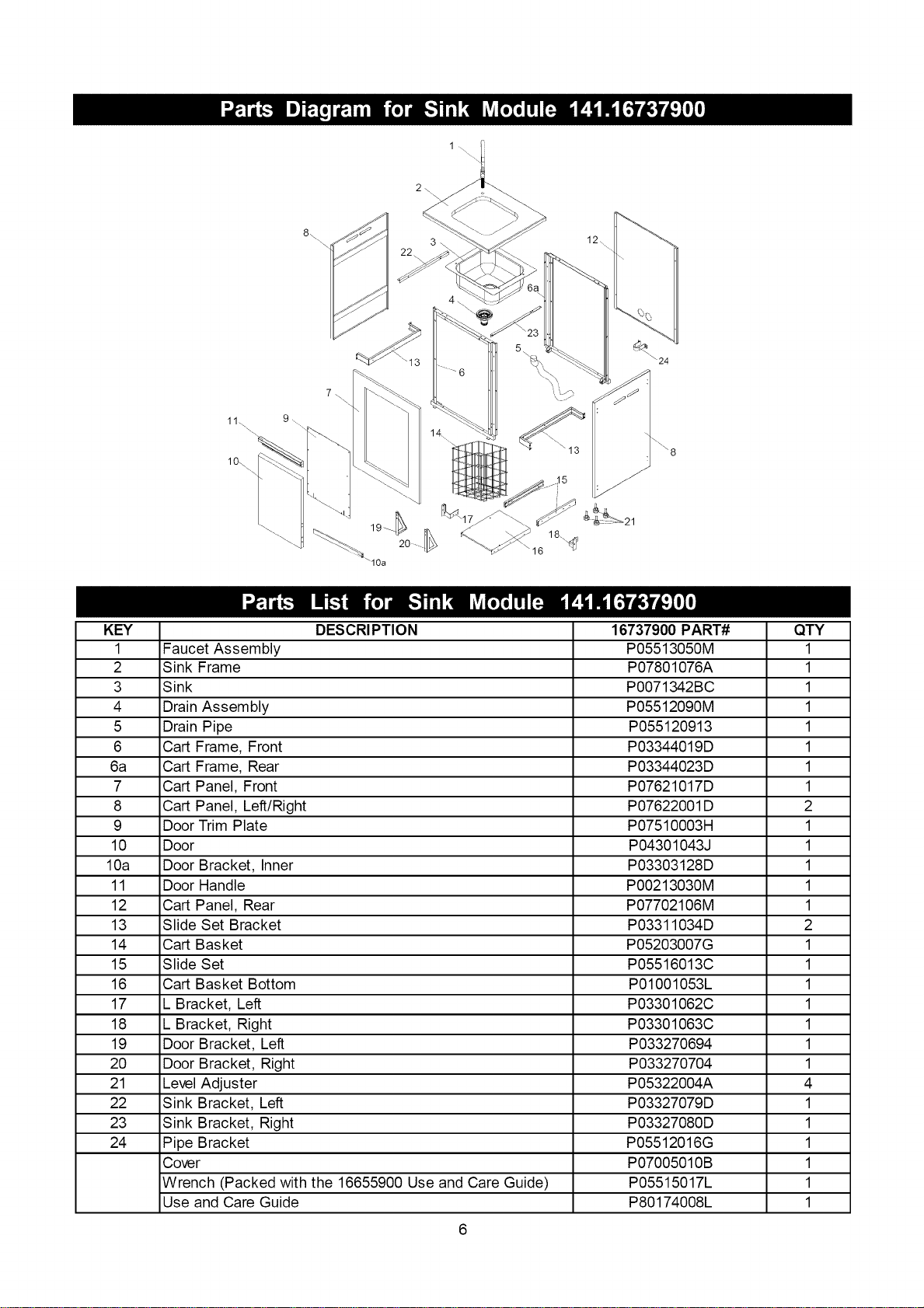
KEY DESCRI PTION 16737900 PART# QTY
1 Faucet Assembly P05513050M 1
2 Sink Frame P07801076A 1
3 Sink P0071342BC 1
4 Drain Assembly P05512090M 1
5 Drain Pipe P055120913 1
6 Cart Frame, Front P03344019D 1
6a Cart Frame, Rear P03344023D 1
7 Cart Panel, Front P07621017D 1
8 Cart Panel, Left/Right P07622001D 2
9 Door Trim Plate P07510003H 1
10 Door P04301043J 1
10a Door Bracket, Inner P03303128D 1
11 Door Handle P00213030M 1
12 Cart Panel, Rear P07702106M 1
13 Slide Set Bracket P03311034D 2
14 Cart Basket P05203007G 1
15 Slide Set P05516013C 1
16 Cart Basket Bottom P01001053L 1
17 L Bracket, Left P03301062C 1
18 L Bracket, Right P03301063C 1
19 Door Bracket, Left P033270694 1
20 Door Bracket, Right P033270704 1
21 Level Adjuster P05322004A 4
22 Sink Bracket, Left P03327079D 1
23 Sink Bracket, Right P03327080D 1
24 Pipe Bracket P05512016G 1
Cover P07005010B 1
Wrench (Packed with the 16655900 Use and Care Guide) P05515017L 1
Use and Care Guide P80174008L 1
- / \\\,
Wrench
Qty.1
Part # P05515017L
(The wrench is not provided, please find it from
16655900 grill pack)
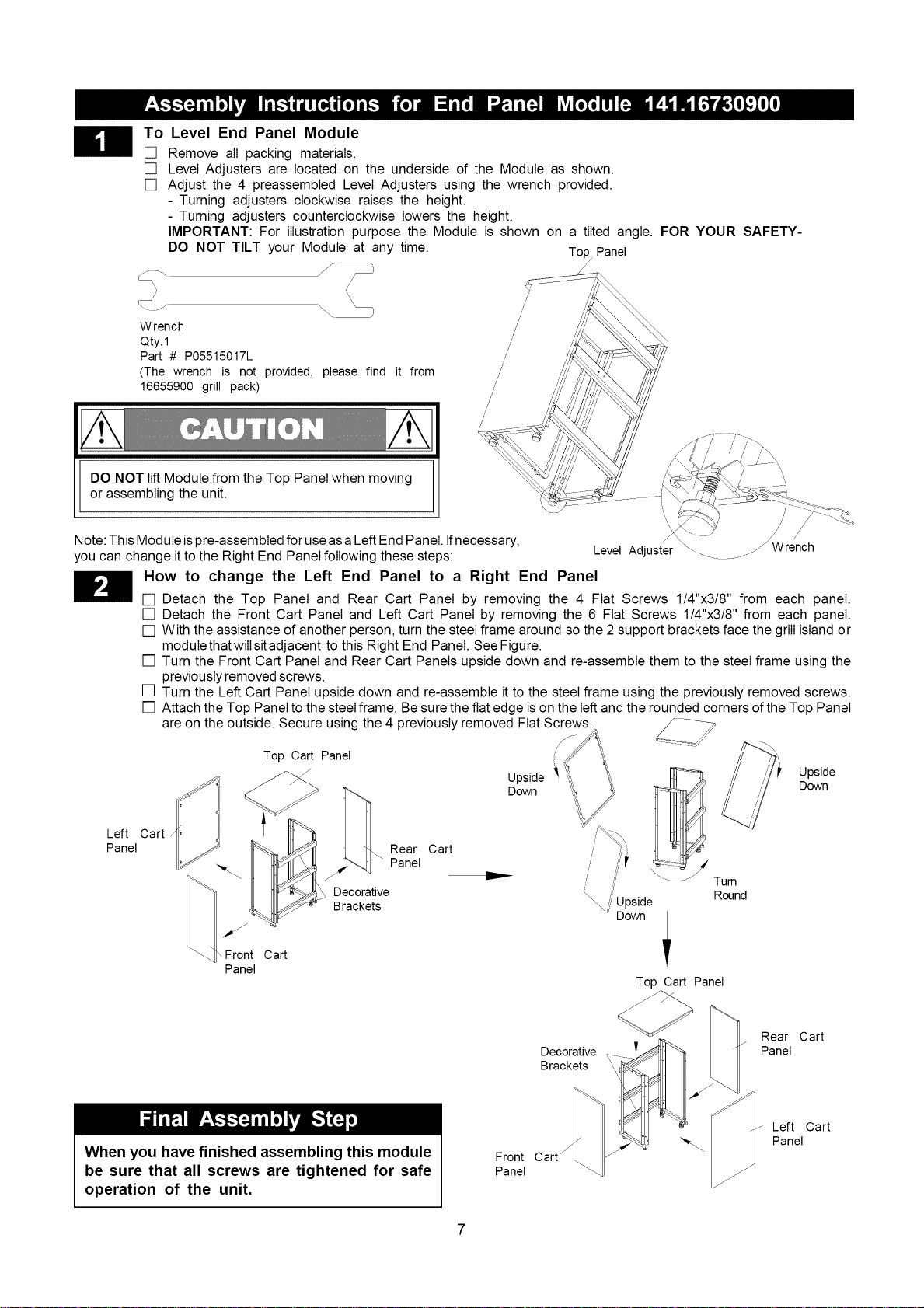
To Level End Panel Module
[] Remove all packing materials.
[] Level Adjusters are located on the underside of the Module as shown.
[] Adjust the 4 preassembted Level Adjusters using the wrench provided.
- Turning adjusters clockwise raises the height.
- Turning adjusters counterclockwise lowers the height.
IMPORTANT: For illustration purpose the Module is shown on a tilted angle. FOR YOUR SAFETY-
DO NOT TILT your Module at any time. Top, Panel
/
j...... j_
V
/
/
/
/
/
/
/
/
/
/
/
/
/
/
/
/'
DO NOT lift Module from the Top Panel when moving
or assembling the unit.
I
/ j/
Level Adjuster _ f Wrench
Note: This Module ispre-assembted for use asa Left End Panel. Ifnecessary,
you can change it to the Right End Panel following these steps:
How to change the Left End Panel to a Right End Panel
[] Detach the Top Panel and Rear Cart Panel by removing the 4 Fiat Screws 1/4"x3/8" from each panel.
[] Detach the Front Cart Panel and Left Cart Panel by removing the 6 Fiat Screws 1/4"x3/8" from each panel.
[] With the assistance of another person, turn the steel frame around so the 2 support brackets face the grill island or
modulethatwilIsitadjacent to this Right End Panel. See Figure.
[] Turn the Front Cart Panel and Rear Cart Panels upside down and re-assemble them to the steel frame using the
previously removed screws.
[] Turn the Left Cart Panel upside down and re-assemble it to the steel frame using the previously removed screws.
[] Attach the Top Panel to the steel frame. Be sure the flat edge is on the left and the rounded corners of the Top Panel
are on the outside. Secure using the 4 previously removed Fiat Screws.
Left Cart
Panel
Top Cart Panel
Rear Cart
Panel
Decorative
Brackets
Upside '_
Down
Tum
Round
Upside
Down
Front Cart
Panel
Top Cart Panel
Decorative
Brackets
Rear Cart
Panel
When you have finished assembling this module
be sure that all screws are tightened for safe
operation of the unit.
Front
Panel
Left Cart
Panel
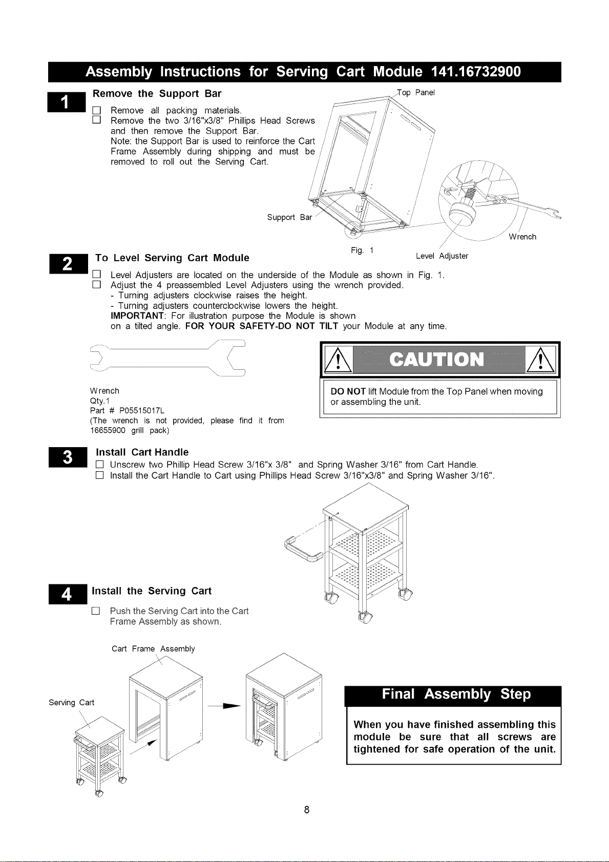
Remove the Support Bar
[] Remove all packing materials.
[] Remove the two 3/16"x3/8" Phillips Head Screws
and then remove the Support Bar.
Note: the Support Bar is used to reinforce the Cart
Frame Assembly during shipping and must be
removed to roll out the Serving Cart.
/
/
/
/
/Top Panel
To Level Serving Cart Module
[]
[]
Support Bar
Fig. 1
/
/i
\- ......./ Wrench
/
Level Adjuster
Level Adjusters are located on the underside of the Module as shown in Fig. 1.
Adjust the 4 preassembted Level Adjusters using the wrench provided.
- Turning adjusters clockwise raises the height.
- Turning adjusters counterclockwise lowers the height.
IMPORTANT: For illustration purpose the Module is shown
on a tilted angle. FOR YOUR SAFETY-DO NOT TILT your Module at any time.
/
Wrench
Qty. 1
Part # P05515017L
(The wrench is not provided, please find it from
16655900 grill pack)
DO NOT lift Module from the Top Panel when moving
or assembling the unit.
H nstall Cart Handle
[] Unscrew two Philip Head Screw 3/16"x 3/8" and Spring Washer 3/16" from Cart Handle.
[] Install the Cart Handle to Cart using Phillips Head Screw 3/16"x3/8" and Spring Washer 3/16".
1_ Install the Serving Cart
[] Push the Serving Cart into the Cart
Frame Assembly as shown.
Cart Frame Assembly
Serving Cart
When you have finished assembling this
module be sure that all screws are
tightened for safe operation of the unit.
8
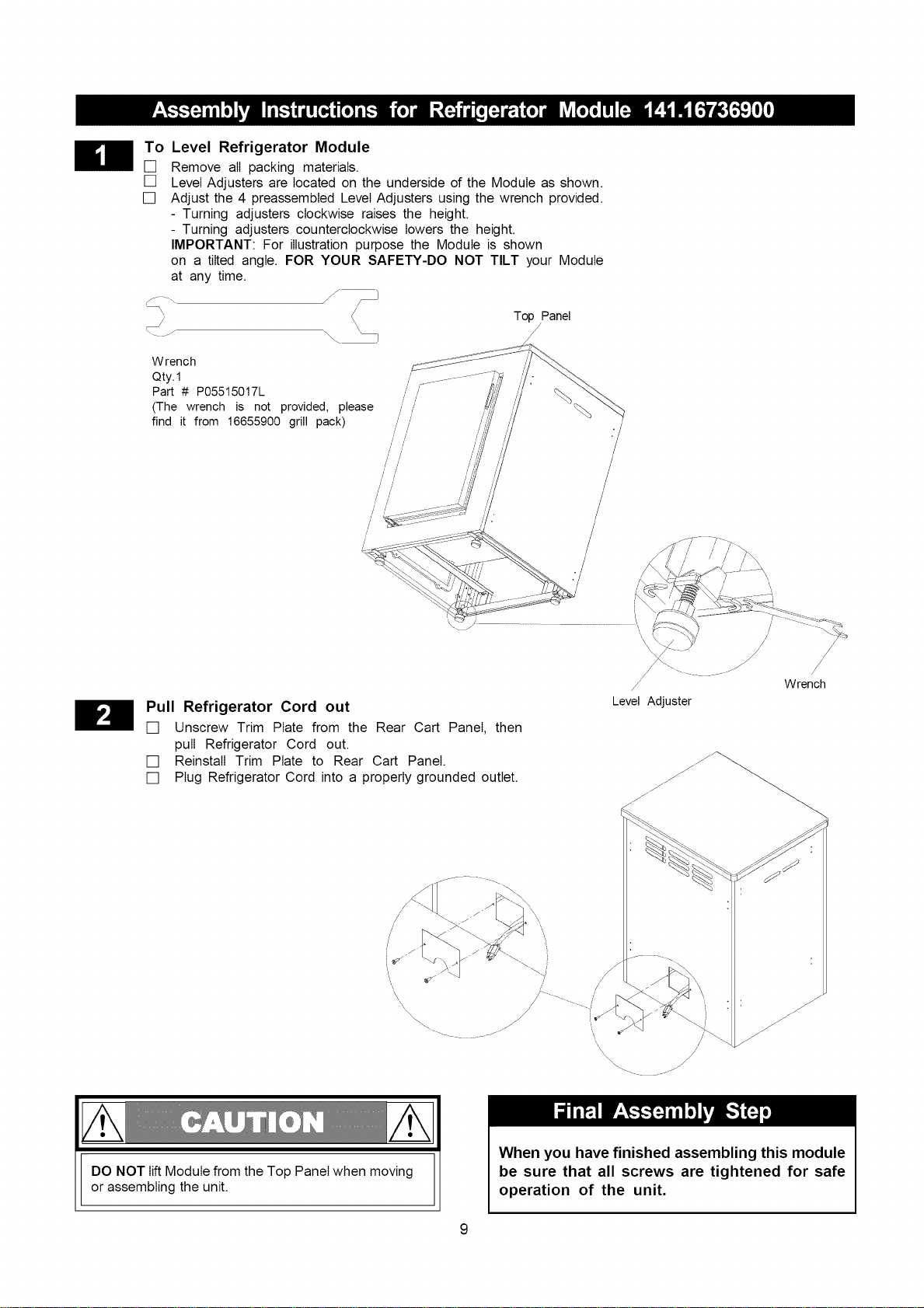
To Level Refrigerator Module
[] Remove all packing materials.
[] Level Adjusters are located on the underside of the Module as shown.
[] Adjust the 4 preassembted Level Adjusters using the wrench provided.
- Turning adjusters clockwise raises the height.
- Turning adjusters counterclockwise lowers the height.
IMPORTANT: For illustration purpose the Module is shown
on a tilted angle. FOR YOUR SAFETY-DO NOT TILT your Module
at any time.
/
\\\\
W rench
Qty. 1
Part # P05515017L
(The wrench is not provided, please
find it from 16655900 grill pack)
Top Panel
/
/
!
/,
/ /
//
//
//
/
//
//
!/
/
/
/
/
'\
Pull Refrigerator Cord out
[] Unscrew Trim Plate from the Rear Cart Panel, then
pull Refrigerator Cord out.
[] Reinstall Trim Plate to Rear Cart Panel.
[] Plug Refrigerator Cord into a properly grounded outlet.
/
/
Level Adjuster
Wrench
x\\\\
/-
/
/-
DO NOT lift Module from the Top Panel when moving
or assembling the unit.
When you have finished assembling this module
be sure that all screws are tightened for safe
operation of the unit.
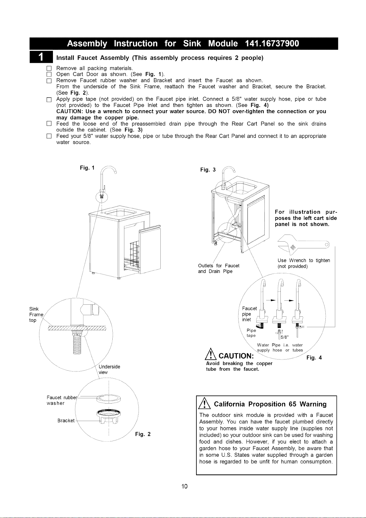
Install FaucetAssembly(Thisassemblyprocessrequires2 people)
[] Remove all packing materials.
[] Open Cart Door as shown. (See Fig. 1).
[] Remove Faucet rubber washer and Bracket and insert the Faucet as shown.
From the underside of the Sink Frame, reattach the Faucet washer and Bracket, secure the Bracket.
(See Fig. 2).
[] Apply pipe tape (not provided) on the Faucet pipe inlet. Connect a 5/8" water supply hose, pipe or tube
(not provided) to the Faucet Pipe Inlet and then tighten as shown. (See Fig. 4)
CAUTION: Use a wrench to connect your water source. DO NOT over-tighten the connection or you
may damage the copper pipe.
[] Feed the loose end of the preassembted drain pipe through the Rear Cart Panel so the sink drains
outside the cabinet. (See Fig. 3)
[] Feed your 5/8" water supply hose, pipe or tube through the Rear Cart Panel and connect it to an appropriate
water source.
Fig. 1
Fig. 3
/
/
For illustration pur-
poses the left cart side
panel is not shown.
\
\
\
/ , Use Wrench to tighten
Outlets for Faucet '\
\ (not provided)
and Drain Pipe
Sink
Frame/
top /_,
i,, /
Bracket ',\ /
\\\\ !
\"... I _ Fig. 2
j
\
\
/
/
/
/
/
/
/
t _upply hose or tubes_
CAUTION: "-.... ..................... Fig. 4
Avoid breaking the copper
tube from the faucet.
Thee California Proposition 65 Warning
outdoor sink module is provided with a Faucet
Assembly. You can have the faucet plumbed directly
to your homes inside water supply line (supplies not
included) so your outdoor sink can be used for washing
food and dishes. However, if you elect to attach a
garden hose to your Faucet Assembly, be aware that
in some U.S. States water supplied through a garden
hose is regarded to be unfit for human consumption.
10
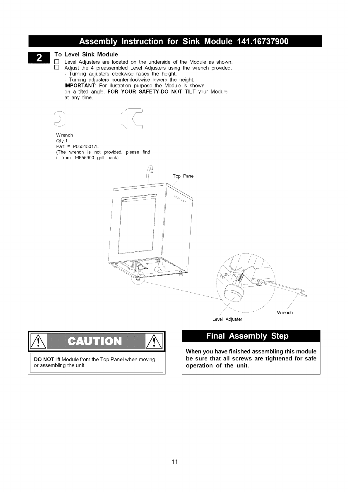
To Level Sink Module
[] Level Adjusters are located on the underside of the Module as shown.
[] Adjust the 4 preassembted Level Adjusters using the wrench provided.
- Turning adjusters clockwise raises the height.
- Turning adjusters counterclockwise lowers the height.
IMPORTANT: For illustration purpose the Module is shown
on a tilted angle. FOR YOUR SAFETY-DO NOT TILT your Module
at any time.
j ...... j-
Wrench
Qty.1
Part # P05515017L
(The wrench is not provided, please find
it from 16655900 grill pack)
_ Top Panel
',.. J
/
/ " ........... Wrench
Level Adjuster
DO NOT lift Module from the Top Panel when moving
or assembling the unit.
When you have finished assembling this module
be sure that all screws are tightened for safe
operation of the unit.
11
Thisappliancemustbegrounded.Intheeventof
an electricalshortcircuitgroundingreducesthe
riskof electricalshockby providingan escape
wirefor theelectricalcurrent.Thisapplianceis
equippedwithacordhavingagroundingwirewith
agroundingplug.Theplugmustbepluggedinto
anoutletthatisproperlyinstalledandgrounded.
Riskof childentrapment.Beforeyouthrowaway
yourold refrigeratoror freezer:
• Takeoff the doors.
• Leavetheshelvesinplacesothat
childrenmaynoteasilyclimbinside.
DON'T WAIT DO IT NOW!
An empty refrigerator is a very dangerous
attraction to children. Remove either the gasket,
latches, lids or doors from unused appliances,
or take some other action that guarantees it
rendered harmless.
Operation
[] Level the cabinet to avoid vibration.
[] To start the refrigerator, turn the control knob
to your desired cooling temperature. The re-
frigerator temperature will vary depending on
the quantity of the food stored and the fre-
quency with which the door is opened.
[] Turn the control to the " O " position to
temporarily discontinue the cooling cycle.
Note: Wait 3 to 5 minutes before restarting if
operation has been interrupted.
Improper use of the grounding plug can result
in a risk of electric shock. Consult a qualified
electrician or service person if the grounding
instructions are not completely understood, or if
the doubt exists as to whether the appliance is
properly grounded.
Use only extension cords approved for outdoor
use marked with W-A and rated for the power
of this appliance.
Do not splice the cord.
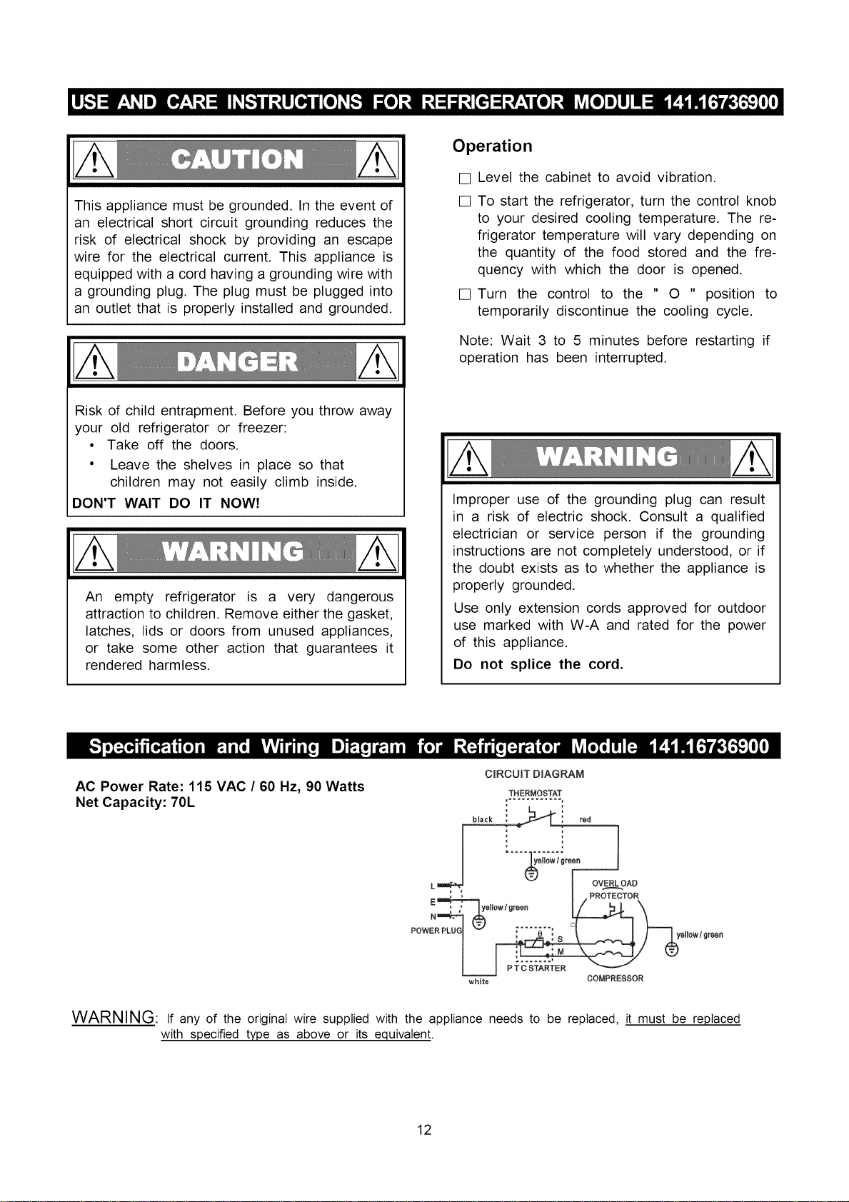
AC Power Rate: 115 VAC / 60 Hz, 90 Watts
Net Capacity: 70L
C_RCUIT DIAGRAM
THERMOSTAT
i .....; °-
L_ - OVER,_LLOAD
white COMPRE88OR
WARNING: If any of the original wire supplied with the appliance needs to be replaced, it must be replaced
with specified type as above or its equivalent.
12
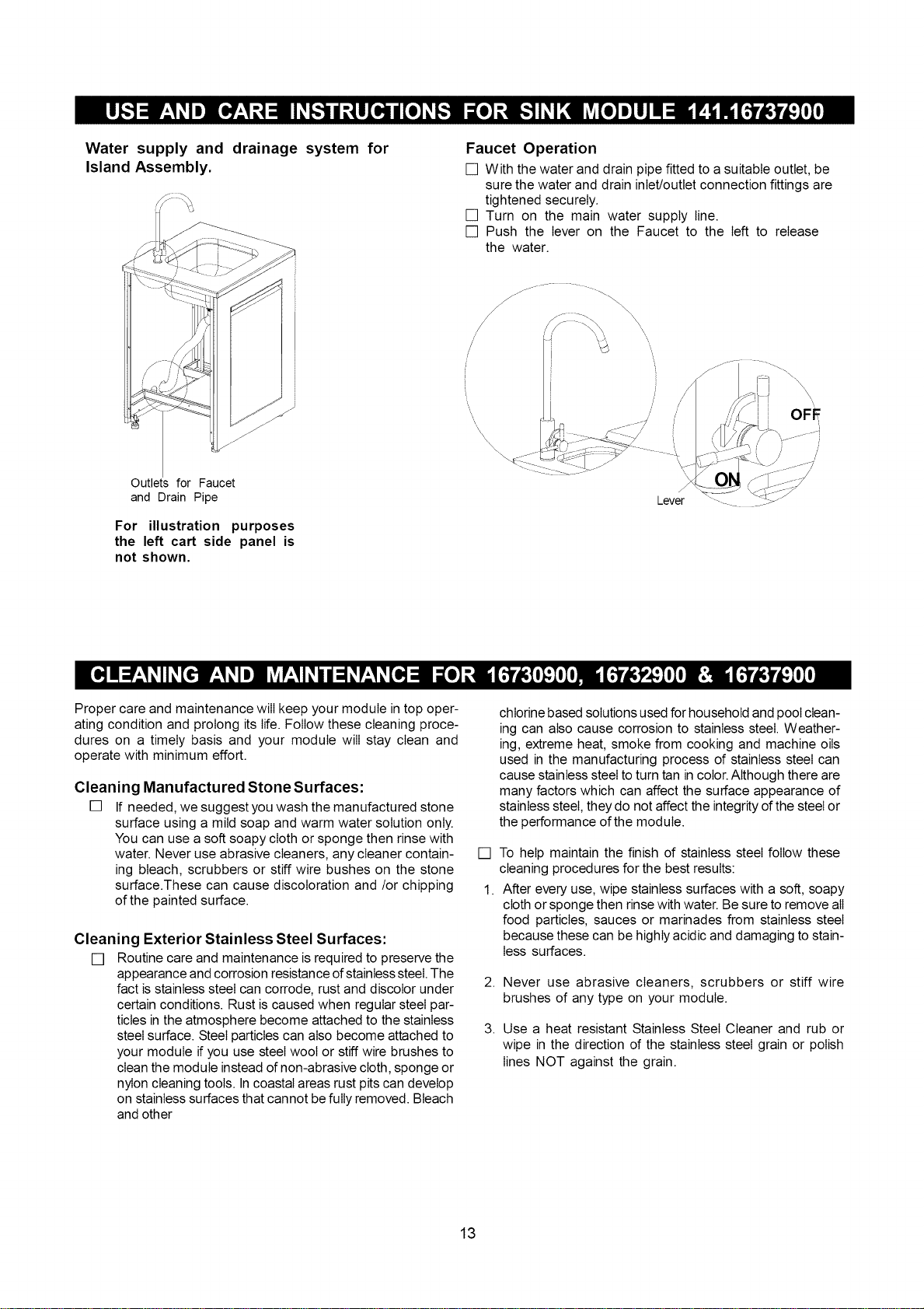
Water supply and
Island Assembly.
drainage system for Faucet Operation
[] With the water and drain pipe fitted to a suitable outlet, be
sure the water and drain inlet/outlet connection fittings are
tightened securely.
[] Turn on the main water supply line.
[] Push the lever on the Faucet to the left to release
the water.
/
Outlets for Faucet
and Drain Pipe
For illustration purposes
the left cart side panel is
not shown.
Lever
/
Proper care and maintenance will keep your module in top oper-
ating condition and prolong its life. Follow these cleaning proce-
dures on a timely basis and your module will stay clean and
operate with minimum effort.
Cleaning Manufactured Stone Surfaces:
[] If needed, we suggest you wash the manufactured stone
surface using a mild soap and warm water solution only.
You can use a soft soapy cloth or sponge then rinse with
water. Never use abrasive cleaners, any cleaner contain-
ing bleach, scrubbers or stiff wire bushes on the stone
surface.These can cause discoloration and/or chipping
of the painted surface.
Cleaning Exterior Stainless Steel Surfaces:
[] Routine care and maintenance is required to preserve the
appearance and corrosion resistance ofstainless steel. The
fact is stainless steel can corrode, rust and discolor under
certain conditions. Rust is caused when regular steel par-
ticles in the atmosphere become attached to the stainless
steel surface. Steel particles can also become attached to
your module if you use steel wool or stiff wire brushes to
clean the module instead of non-abrasive cloth, sponge or
nylon cleaning tools. In coastal areas rust pits can develop
on stainless surfaces that cannot be fully removed. Bleach
and other
chlorine based solutions used for household and pool clean-
ing can also cause corrosion to stainless steel. Weather-
ing, extreme heat, smoke from cooking and machine oils
used in the manufacturing process of stainless steel can
cause stainless steel to turn tan in color.Although there are
many factors which can affect the surface appearance of
stainless steel, they do not affect the integrity of the steel or
the performance of the module.
[]
1.
To help maintain the finish of stainless steel follow these
cleaning procedures for the best results:
After every use, wipe stainless surfaces with a soft, soapy
cloth or sponge then rinse with water. Be sure to remove all
food particles, sauces or marinades from stainless steel
because these can be highly acidic and damaging to stain-
less surfaces.
2. Never use abrasive cleaners, scrubbers or stiff wire
brushes of any type on your module.
3. Use a heat resistant Stainless Steel Cleaner and rub or
wipe in the direction of the stainless steel grain or polish
lines NOT against the grain.
13
CleaningRefrigerator
To clean the inside, use a soft cloth and a solution of a
table spoon of baking soda to one quart of water, or a
mild soap suds solution, or some mild detergent. Wash drip
tray and glide out shelves in a mild detergent solution, then
dry and wipe with a soft cloth. Clean the outside with a
soft damp cloth and some mild detergent or appliance
cleaner.
Vacation Time
For short vacation periods, leave the control knobs at their
usual settings. During longer absences, (a)remove all foods,
(b) disconnect from electrical outlet, (c) clean the refrig-
erator thoroughly, (d) leave door open to avoid possible
formations of condensation, mold or odors.
Power Failure
Most power failures are corrected within an hour or two
and will not affect your refrigerator temperatures. However,
you should minimize the number of door openings while
the power is off. During power failure of longer duration,
take steps to protect your food by placing ice on top of
packages.
Correct Use
Some Important Rules for the Correct Use of the
Refrigerator
• Never place hot foods in the refrigerator.
• Beverages should be stored in sealed containers.
• Foods to be stored for a long time should be wrapped
in cellophane or polyethylene, or kept in glass containers.
Never place spoiled foods in the cabinet.
• Don't overload the cabinet.
• Don't open the door unless necessary.
If the refrigerator will be stored without use for long
periods it is suggested, after a careful cleaning, to leave
the door ajar to allow the air to circulate inside the cabinet
in order to avoid possible formations of condensation,
mold or odors.
If you have any problem with the refrigerator
please call the:
Information Center 1-888-317-7642
8am-8pm CST, Monday throuqh Friday
14
Congratulations on making a smart purchase. Your new Kenmore ®product is designed and manufactured for years of
dependable operation. But like all products, it may require repair from time to time. That's when having a Repair
Protection Agreement can save you money and aggravation.
Here's what the Repair Protection Agreement* includes:
[]
[]
[]
[]
[]
Expert service by our 10,000 professional repair specialists.
Unlimited service and no charge for parts and labor on all covered repairs.
Product replacement up to $1500 if your covered product can't be fixed.
Discount of 10% from regular price of service and related installed parts not covered by the agreement;
also, 10% off regular price of preventative maintenance check.
Fast help by phone - we call it Rapid Resolution - phone support from a Sears representative. Think of us
as a "talking Use and Care Guide."
Once you purchase the Repair Protection Agreement, a simple phone call is all that it takes for you to schedule service.
You can call anytime day or night, or schedule a service appointment online.
The Repair Protection Agreement is a risk-free purchase. If you cancel for any reason during the product warranty period,
we will provide a full refund. Or, a prorated refund anytime after the product warranty period expires. Purchase your
Repair Protection Agreement today!
Some limitations and exclusions apply. For prices and additional information in the U.S.A. call 1-800-827-6655.
* Coverage in Canada varies on some items. For full details call Sears Canada at 1-800-361-6665.
Sears Installation Service
For Sears professional installation of home appliances, garage door openers, water heaters, and other major home
items, in the U.S.A. or Canada call 1-800-4-MY-HOME ®.
15
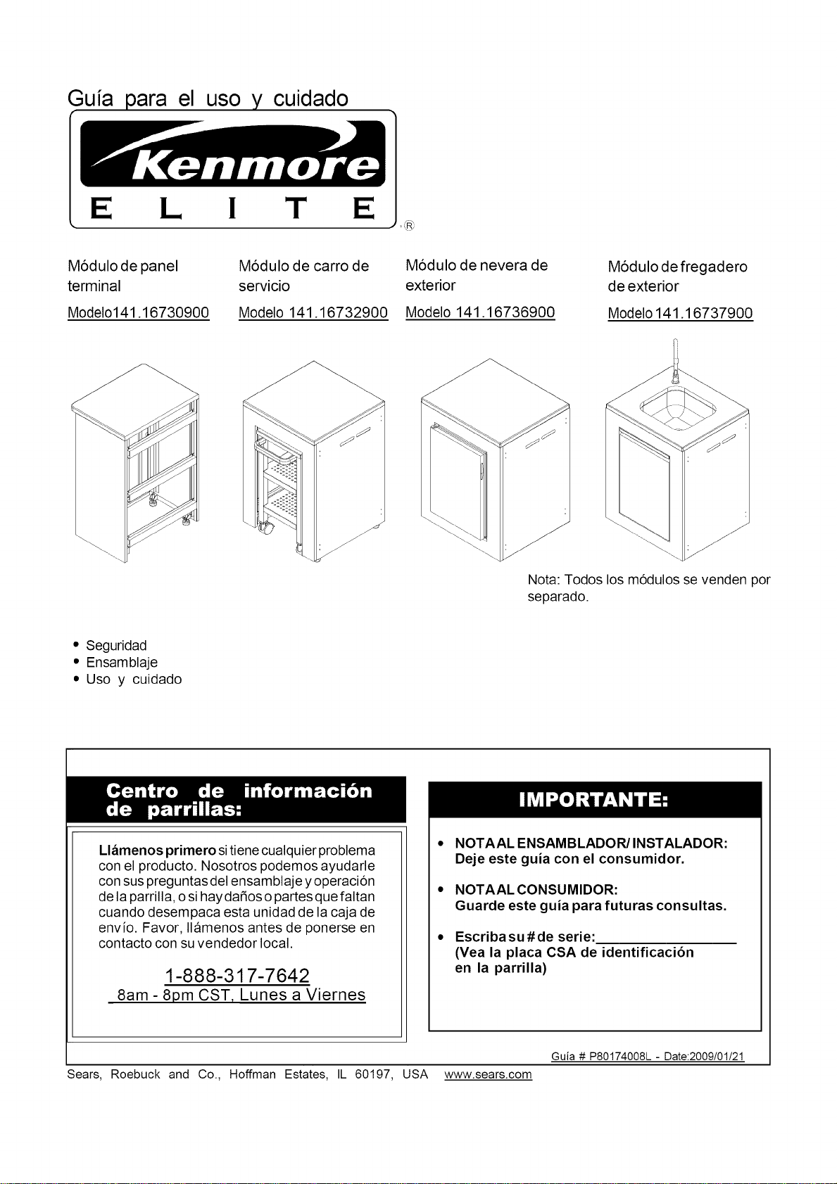
Guia el uso cuidado
E L I T E
_®
Modulo de panel
terminal
Modelo141.16730900
M6dulo de carro de
servicio
Modelo 141.16732900
Modulo de nevera de
exterior
Modelo 141.16736900
Modulo de fregadero
de exterior
Modelo 141.16737900
Nota: Todos los m6dulos se venden por
separado.
• Seguridad
• Ensamblaje
• Uso y cuidado
Llamenos primero sitiene cualquier problema
con el producto. Nosotros podemos ayudarle
con sus preguntas del ensamblaje y operaci6n
de la parrilla, o si hay daSos o partes que faltan
cuando desempaca esta unidad de la caja de
envio. Favor, Ilamenos antes de ponerse en
contacto con su vendedor local.
1-888-317-7642
8am- 8pm CST, Lunes a Viernes
NOTAAL ENSAMBLADOR/INSTALADOR:
Deje este guia con el consumidor.
NOTAAL CONSUMIDOR:
Guarde este guia para futuras consultas.
Escriba su # de serie:
(Yea la placa CSA de identificaci6n
en la parrilla)
Guia # P80174008L- Date:2009/01/21
Sears, Roebuck and Co., Hoffman Estates, IL 60197, USA www.sears.com
Advertencias de Seguridad principales ............. 2
T6rminos y condiciones de la garantia ............ 2
Instrucciones para antes del ensamblaje .......... 2
Diagrama de partes y listas .................... 3-6
Instrucciones para el ensamblaje .............. 7-11
Instrucciones para uso y cuidado .............. 12-13
Instrucciones para montar el rotisor y la
brocheta ...................................................... 13-14
Acuerdos de protecci6n de reparos ............. 15
Garantia completa del Kenmore Elite
Siesta parrilla falla en funcionar debido a un defecto
en el material o trabajo de obra dentro del periodo
de uno afio de la fecha de compra,llame a Sears al
1-800-8-MY-HOME ® (1-800-469-4663) para
organizar la reparaci6n gratuita (o sustituci6n si la
reparaci6n prueba ser imposible).
Garantia Limitada en partes selectas de la
parrilla
Durante los tres afios siguientes a la fecha de
compra, cualquier pieza de acero inoxidable o
acero pintado se cambiara sin cargo si se oxida.
Pasado el segundo afio desde la fecha de
compra debe cubrir los gastos de mano de obra
para instalarlo.
Toda cobertura de garantia excluye las baterias del
encendedor y p6rdida de pintura en partes de la parrilla
o corrosi6n (excepto por corrosi6n a trav6s como se
especifica arriba), las cuales son partes prescindibles
por el desgaste del uso normal en menos de un afio,
o son condiciones que pueden resultar por uso nor-
mal, accidente o mantenimiento incorrecto.
Se anula toda la Garantia si la parrilla es puesta en
usos comerciales o es alquilada.
Esta garantia aplica solamente cuando la parrilla es
usada en los Estados Unidos.
Esta garantia le confiere derechos legales especificos
y pueda ser que tenga otros derechos que varian de
un estado al otro.
Sears, Roebuck and Co., Hoffman Estates, IL
© Sears Brands, LLC
[]
[]
[]
[]
Para apresurar el proceso de ensamblaje siga las
siguientes instrucciones generales:
Herramientas requeridas para el ensamble:
• DestornilIador con cabeza Phillips
Necesitara ayuda de otra persona para manipuIar
esta barbacoa e isIa.
Use el diagramas de partes y ferreteria para asegurarse
que todas Ias partes estan incIuidas y Iibres de dafios.
No ensambte u opere Ia parrilIa si parece que algo iesta
dafiado. Si hay dafios o partes que faItan cuando
desempaca Ia parriIIa de Ia caja de envio ousted tiene
preguntas sobre el proceso deI ensambtaje, IIame al:
Centro de informaci6n de Parrillas 1-888-317-7642
//_ Advertencia 65 de las Sugerencias
de California
Este producto incIuye un grifo. Puede conectar
directamente el grifo a su Iinea de agua corriente
domestica (materialno incluido)para que su fregadero
de exterior pueda usarse para Iimpiar los alimentos y
los ptatos. Sin embargo, si prefiere acoptar una
manguera de jardin a su grifo, tenga en cuenta que,
en algunos estados de EE.UU., el agua proporcionada
mediante una manguera de jardin se considera
inadecuada para el consumo humano.
Cuando use aparatos el6ctricos siempre se deben
seguir unas precauciones de seguridad basicas.
Este aparato, cuando se ha instalado, puede
conectarse electricamente a tierra segQn los
c6digos locales o en ausencia de los c6digos
locales con el c6digo electrico nacional, ANSI/
NFPA 70 o el c6digo electrico canadiense CSA
C22.1.
Mantenga cualquier cable electrico y la manguera
de suministro de combustible lejos de las
superficies calientes.
5-_ .
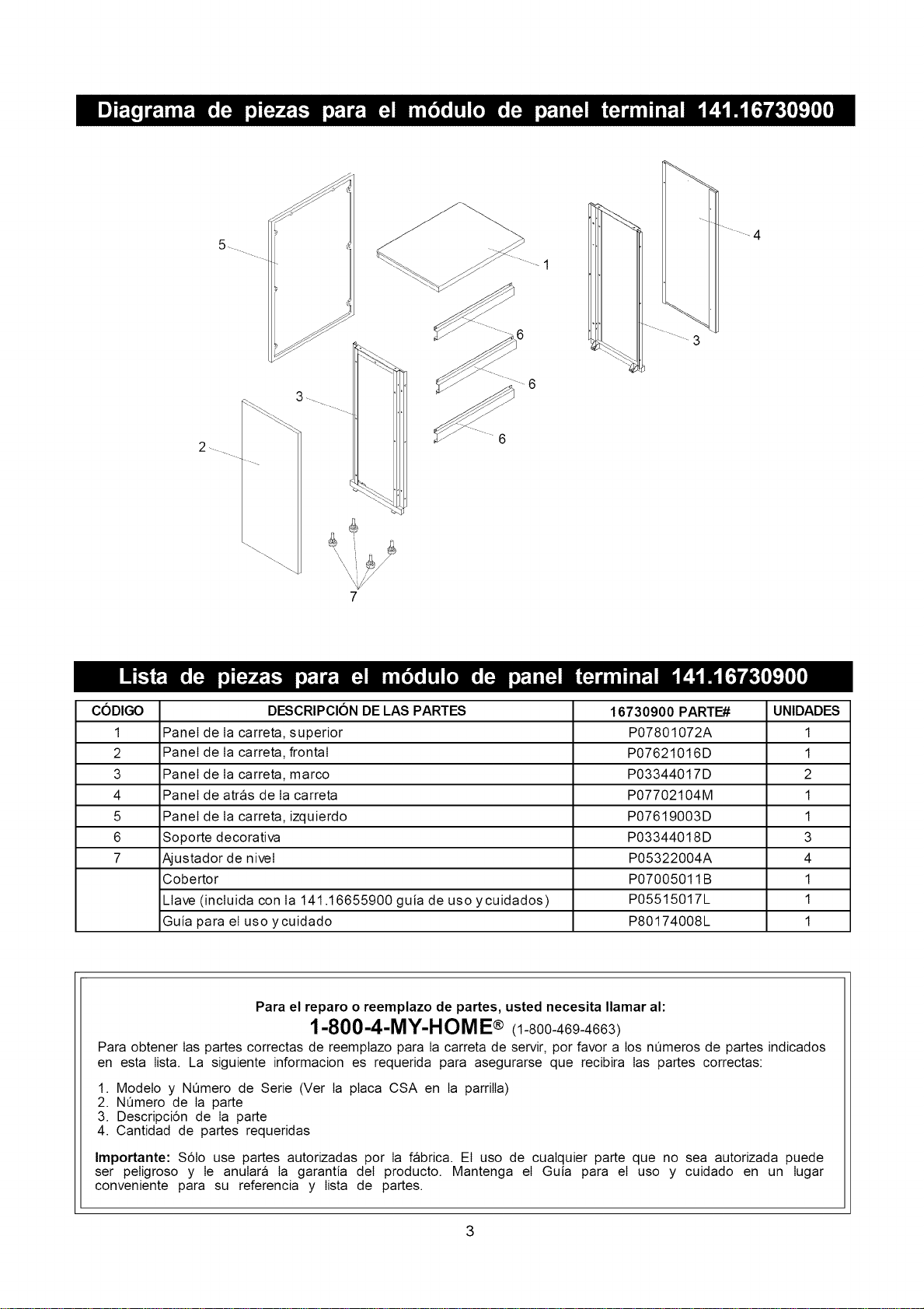
3
CODIGO DESCRIPCION DE LAS PARTES 16730900 PARTE# UNIDADES
1 Panel de Ia carreta, superior P07801072A 1
2 Panel de Ia carreta, frontal P07621016D 1
3 Panel de Ia carreta, marco P03344017D 2
4 Panel de atras de Ia carreta P07702104M 1
5 Panel de Ia carreta, izquierdo P07619003D 1
6 Soporte decorativa P03344018D 3
7 Ajustador de niveI P05322004A 4
Cobertor P07005011 B 1
Llave (incluida con Ia 141.16655900 guia de uso ycuidados) P05515017L 1
Guia para el uso ycuidado P80174008L 1
Para el reparo o reemplazo de partes, usted necesita Ilamar al:
1-800-4-MY-HOM E® (1-800-469-4663)
Para obtener Ias partes correctas de reemptazo para Ia carreta de servir, por favor a los n_meros de partes indicados
en esta Iista. La siguiente informacion es requerida para asegurarse que recibira Ias partes correctas:
1. Modelo y NQmero de Serie (Ver Ia ptaca CSA en Ia parrilIa)
2. NQmero de Ia parte
3. Descripci6n de Ia parte
4. Cantidad de partes requeridas
Importante: S6Io use partes autorizadas por Ia fabrica. El uso de cuaIquier parte que no sea autorizada puede
ser peIigroso y Ie anuIara Ia garantia deI producto. Mantenga el Guia para el uso y cuidado en un Iugar
conveniente para su referencia y Iista de partes.
3
13a
11
1
J
4
2
_12
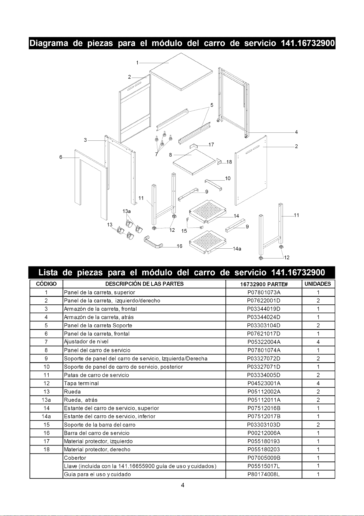
CODIGO 16732900 PARTE# UNIDADES
1 P07801073A 1
2 P07622001D 2
3 P03344019D 1
4 P03344024D 1
5 P03303104D 2
6 P07621017D 1
7 P05322004A 4
8 P07801074A 1
9 P03327072D 2
10 P03327071D 1
11 P03334005D 2
12 P04523001A 4
13 P05112002A 2
13a P05112011A 2
14 P07512016B 1
14a P07512017B 1
15 P03303103D 2
16 P00212006A 1
17 P055180193 1
18 P055180203 1
P07005009B 1
P05515017L 1
P80174008L 1
DESCRIPClON DE LAS PARTES
Panel de Ia carreta, superior
Panel de Ia carreta, izquierdo/derecho
Armaz6n de Ia carreta, frontal
Armaz6n de Ia carreta, atras
Panel de Ia carreta Soporte
Panel de Ia carreta, frontal
Ajustador de niveI
Panel deI carro de servicio
Soporte de panel deI carro de servicio, Izquierda/Derecha
Soporte de panel de carro de servicio, posterior
Patas de carro de servicio
Tapa terminal
Rueda
Rueda, atras
Estante deI carro de servicio, superior
Estante deI carro de servicio, inferior
Soporte de Ia barra deI carro
Barra deI carro de servicio
Material protector, izquierdo
Material protector, derecho
Cobertor
LIave (incIuida con Ia 141.16655900 guia de uso ycuidados)
Guia para el uso ycuidado
4
2 _
_ 7 _ .
lO
11
9
"6
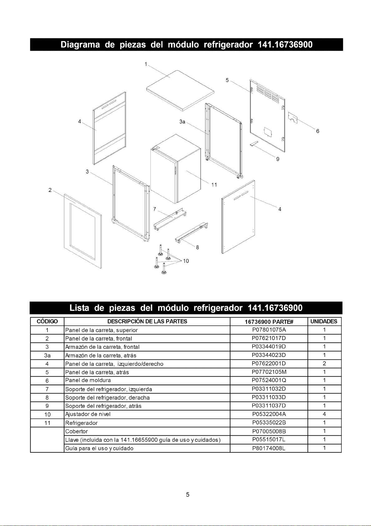
CODIGO DESCRIPCION DE LAS PARTES 16736900 PARTE# UNIDADES
1 Panel de la carreta, superior P07801075A 1
2 Panel de la carreta, frontal P07621017D 1
3 Armaz6n de la carreta, frontal P03344019D 1
3a Armaz6n de la carreta, atrfis P03344023D 1
4 Panel de la carreta, izquierdo/derecho P07622001D 2
5 Panel de la carreta, atras P07702105M 1
6 Panel de motdura P07524001Q 1
7 Soporte det refrigerador, izquierda P03311032D 1
8 Soporte det refrigerador, deracha P03311033D 1
9 Soporte det refrigerador, atras P03311037D 1
10 Ajustador de nivet P05322004A 4
11 Refrigerador P05335022B 1
Cobertor P07005008B 1
Llave (incluida con la 141.16655900 guia de uso ycuidados) P05515017L 1
Guia para el uso y cuidado P80174008L 1
4\
12\
7 \
\
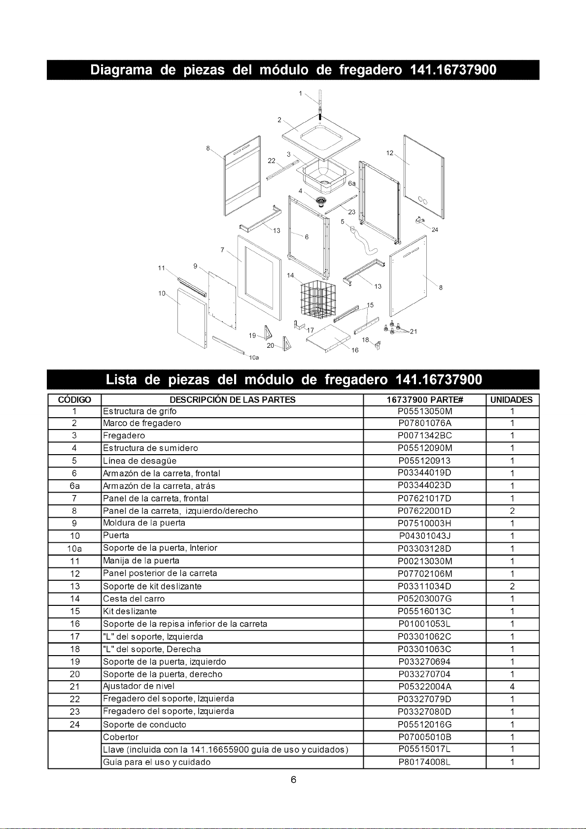
CODIGO DESCRIPCION DE LAS PARTES 16737900 PARTE# UNIDADES
1 Estructura de grifo P05513050M 1
2 Marco de fregadero P07801076A 1
3 Fregadero P0071342BC 1
4 Estructura de sumidero P05512090M 1
5 Linea de desagee P055120913 1
6 Armaz6n de Ia carreta, frontal P03344019D 1
6a Armaz6n de Ia carreta, atras P03344023D 1
7 Panel de Ia carreta, frontal P07621017D 1
8 Panel de Ia carreta, izquierdo/derecho P07622001D 2
9 MoIdura de Ia puerta P07510003H 1
10 Puerta P04301043J 1
10a Soporte de Ia puerta, Interior P03303128D 1
11 Manija de Ia puerta P00213030M 1
12 Panel posterior de Ia carreta P07702106M 1
13 Soporte de kit desIizante P03311034D 2
14 Cesta deI carro P05203007G 1
15 Kit desIizante P05516013C 1
16 Soporte de Ia repisa inferior de Ia carreta P01001053L 1
17 "L" deI soporte, Izquierda P03301062C 1
18 "L" deI soporte, Derecha P03301063C 1
19 Soporte de Ia puerta, izquierdo P033270694 1
20 Soporte de Ia puerta, derecho P033270704 1
21 Ajustador de niveI P05322004A 4
22 Fregadero deI soporte, Izquierda P03327079D 1
23 Fregadero deI soporte, Izquierda P03327080D 1
24 Soporte de conducto P05512016G 1
Cobertor P07005010B 1
Llave (incluida con Ia 141.16655900 guia de uso ycuidados) P05515017L 1
Guia para el uso ycuidado P80174008L 1
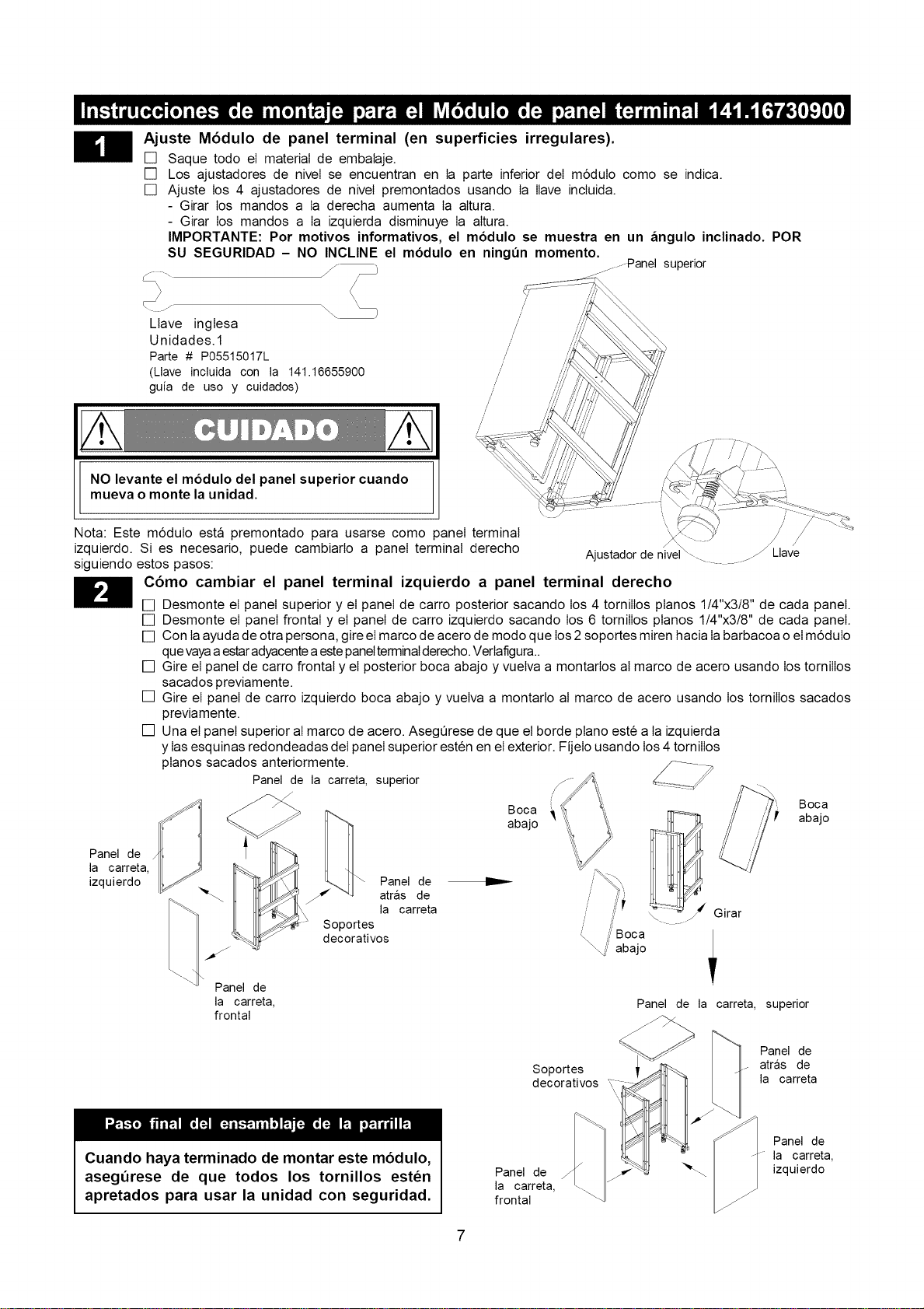
Ajuste M6dulo de panel terminal (en superficies irregulares).
[] Saque todo el material de embalaje.
[] Los ajustadores de niveI se encuentran en Ia parte inferior deI m6dulo como se indic&
[] Ajuste los 4 ajustadores de niveI premontados usando Ia Ilave incluida.
- Girar los mandos a Ia derecha aumenta Ia aItura.
- Girar los mandos a Ia izquierda disminuye Ia aItura.
IMPORTANTE: Por motivos informativos, el modulo se muestra en un fingulo inclinado. POR
SU SEGURIDAD - NO INCLINE el modulo en ningun momento.
i_ \\
/
/
Llave inglesa /
/
Unidades.1 /
/
Parte # P05515017L /
/
(Llave incluida con la 141.16655900 /
/
guia de uso y cuidados) /
/
/
/
/
/
NO levante el modulo del panel superior cuando
mueva o monte la unidad.
Nota: Este m6dulo estfi premontado para usarse como panel terminal
izquierdo. Si es necesario, puede cambiarto a panel terminal derecho
siguiendo estos pasos:
........Panel superior
Panel de
la carreta,
izquierdo
/
\ /
/ j/
Y Llave
Ajustadorde nivel\- ..............
C6mo cambiar el panel terminal izquierdo a panel terminal derecho
[] Desmonte el panel superior y el panel de carro posterior sacando los 4 tornilIos ptanos 1/4"x3/8" de cada panel.
[] Desmonte el panel frontal y el panel de carro izquierdo sacando los 6 tornilIos ptanos 1/4"x3/8" de cada panel.
[] Con Iaayuda de otra persona, gire el marco de acero de modo que los 2 soportes miren hacia Iabarbacoa oel m6dulo
quevayaaestaradyacentea estepanelterminalderecho. Vertafigura..
[] Gire el panel de carro frontal y el posterior boca abajo y vuelva a montartos al marco de acero usando los tornilIos
sacados previamente.
[] Gire el panel de carro izquierdo boca abajo y vuelva a montarto al marco de acero usando los tornilIos sacados
previamente.
[] Una el panel superior aI marco de acero. AsegOrese de que el borde ptano este a Iaizquierda
y Iasesquinas redondeadas deI panel superior esten en el exterior. Fijelo usando los4 tornilIos
ptanos sacados anteriormente.
Panel de la carreta, superior
Panel de
la carreta,
frontal
Panel de
atrfis de
la carreta
Soportes
decorativos
Boca
abajo
_i:" abajo
_" Girar
Boca
abajo
Panel de la carreta, superior
Soportes
decorativos
Panel de
atras de
la carreta
Cuando haya terminado de montar este m6dulo,
aseg_rese de que todos los tornillos esten
apretados para usar la unidad con seguridad.
Panel de
la carreta,
frontal
/
Panel de
la carreta,
"_\ izquierdo
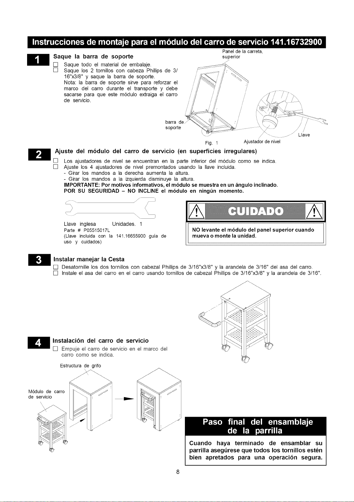
Saque la barra de soporte
[] Saque todo el material de embalaje.
[] Saque los 2 tornillos con cabeza Phillips de 3/
16"x3/8" y saque Ia barra de soporte.
Nota: Ia barra de soporte sirve para reforzar el
marco deI carro durante el transporte y debe
sacarse para que este m6dulo extraiga el carro
de servicio.
barra
soporte
Panel de la carreta,
superior
J
Fig. 1
Ajuste del m6dulo del carro de servicio (en superficies irregulares)
[]
[]
Ajustador de nivel
Los ajustadores de niveI se encuentran en Ia parte inferior deI m6duIo como se indica.
Ajuste los 4 ajustadores de niveI premontados usando Ia Ilave incluida.
- Girar los mandos a Ia derecha aumenta Ia altura.
- Girar los mandos a Ia izquierda disminuye Ia altura.
IMPORTANTE: Por motivos informativos, el modulo se muestra en un angulo inclinado.
POR SU SEGURIDAD - NO INCLINE el modulo en ningun momento.
Llave
Llave ingtesa Unidades. 1
Pa_e # P05515017L
(Llave incluida con la 141.16655900 guia de
uso y cuidados)
NO levante el modulo del panel superior cuando
mueva o monte la unidad.
_'_ Instalar manejar la Cesta
[] DesatornilIe los dos tornilIos con cabezaI Phillips de 3/16"x3/8" y Ia arandela de 3/16" deI asa deI carro.
[] Instale el asa deI carro en el carro usando tornilIos de cabezal Phillips de 3/16"x3/8" y Ia arandela de 3/16".
H Instalaci6n del carro de servicio
[] Empuje el carro de servicio en el marco del
carro como se indic&
Estructura de grifo
M6dulo de carro
de servicio
Cuando haya terminado de ensamblar su
parrilla asegerese que todos los tornillos esten
bien apretados para una operaci6n segura.
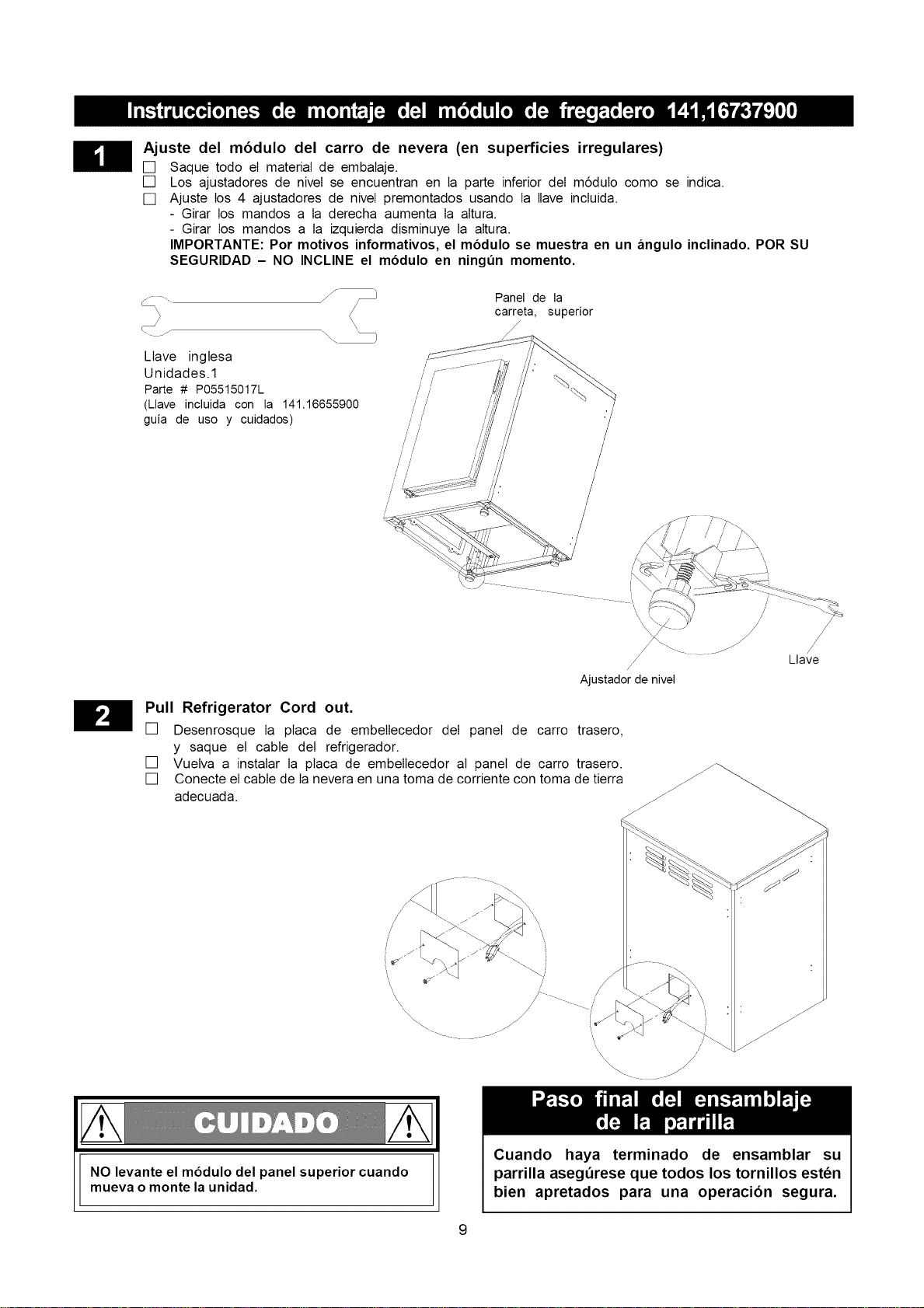
Ajuste del m6dulo del carro de nevera (en superficies irregulares)
[] Saque todo el material de embalaje.
[] Los ajustadores de niveI se encuentran en Ia parte inferior deI m6dulo como se indica.
[] Ajuste los 4 ajustadores de niveI premontados usando Ia Ilave incluida.
- Girar los mandos a Ia derecha aumenta Ia aItura.
- Girar los mandos a la izquierda disminuye Ia aItura.
IMPORTANTE: Por motivos informativos, el modulo se muestra en un angulo inclinado. POR SU
SEGURIDAD - NO INCLINE el modulo en ningun momento.
f _ Panel de la
/ carreta, superior
<
Llave inglesa
Unidades.1
Parte # P05515017L
(Llave incluida con la 141.16655900
guia de uso y cuidados)
/ /
/ /
/
/
/
/
Ajustadorde nivel
H Pull Refrigerator Cord out.
[] Desenrosque Ia ptaca de embelIecedor deI panel de carro trasero,
y saque el cable deI refrigerador.
[] Vuelva a instalar Ia ptaca de embelIecedor aI panel de carro trasero.
[] Conecte el cable de Ia nevera en una toma de corriente con toma de tierra
adecuada.
/ \\
/
//
/
/
/
Llave
\
\\
"\\\
/
\\\
J
J
_J
J
J
J
J
J
J
NO levante el modulo del panel superior cuando
mueva o monte la unidad.
Cuando haya terminado de ensamblar su
parrilla aseg_rese que todos los tornillos esten
bien apretados para una operaci6n segura.
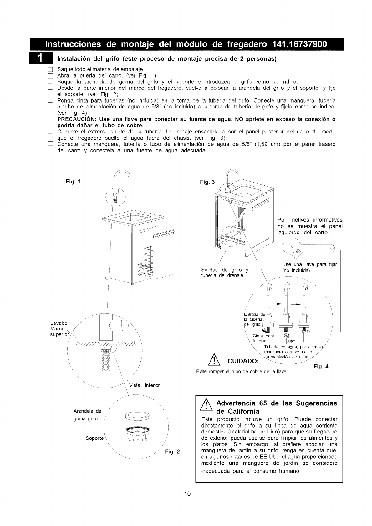
Instalaci6ndel grifo (este proceso de montaje precisa de 2 personas)
[] Saque todo el material de embalaje.
[] Abra Ia puerta deI carro. (ver Fig. 1)
[] Saque Ia arandela de goma deI grifo y el soporte e introduzca el grifo como se indica.
[] Desde Ia parte inferior deI marco deI fregadero, vuelva a colocar Ia arandela deI grifo y el soporte, y fije
el soporte. (ver Fig. 2)
[] Ponga cinta para tuberias (no incluida) en Ia toma de Ia tuberia deI grifo. Conecte una manguera, tuberia
o tubo de alimentacidn de agua de 518" (no incluido) a Ia toma de tuberia de grifo y fijela como se indica.
(ver Fig. 4)
PRECAUCION: Use una Ilave para conectar su fuente de agua. NO apriete en exceso la conexion o
podria dafiar el tubo de cobre.
[] Conecte el extremo suelto de Ia tuberia de drenaje ensambtada por el panel posterior deI carro de modo
que el fregadero suelte el agua fuera deI chasis. (ver Fig. 3)
[] Conecte una manguera, tuberia o tubo de alimentaci6n de agua de 518" (1,59 cm) por el panel trasero
deI carro y conecteIa a una fuente de agua adecuada.
Fig. 1
f
J
Lavabo
Marco.
superior j_
\
\
\
\ /
\
\ /
\
.z_ Vista
\
inferior
/ ! \
Arandela de / \
/
goma grifo ,
' /
Soporte", /
i
\\\ !
"-\. I _ Fig. 2
Fig. 3
/
/ '\
\
/ \
Salidas de grifo y '\\
tuberia de drenaje \
Por motivos informativos
no se muestra el panel
izquierdo deI carro.
Use una Ilave para fijar
(no incluida)
\,,
\
L
/
/
/
',\ Cinta para {:4_t /
'\ tuberias [5/8" /
Tuberia de agua, por ejempl£
_ manguera o tuberias de_
t CUIDADO: _imentaci6n de agua/
Fig. 4
Evite romper el tubo de cobre de la Ilave.
//_ Advertencia 65 de las Sugerencias
de California
Este producto incIuye un grifo. Puede conectar
directamente el grifo a su Iinea de agua corriente
domestica (material no incluido) para que su fregadero
de exterior pueda usarse para Iimpiar los aIimentos y
los ptatos. Sin embargo, si prefiere acoptar una
manguera de jardin a su grifo, tenga en cuenta que,
en aIgunos estados de EE.UU., el agua proporcionada
mediante una manguera de jardin se considera
inadecuada para el consumo humano.
10
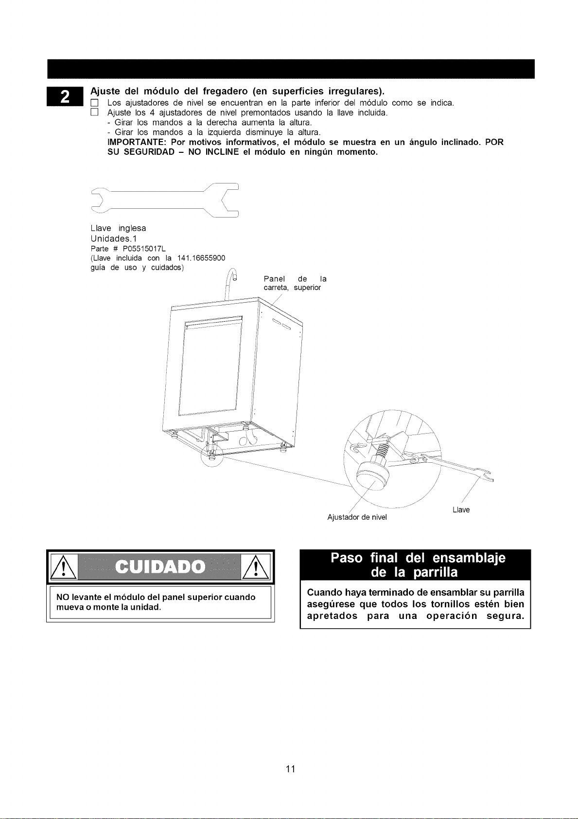
Ajuste del m6dulo del fregadero (en superficies irregulares).
[]
[]
Los ajustadores de niveI se encuentran en Ia parte inferior deI m6dulo como se indica.
Ajuste los 4 ajustadores de niveI premontados usando Ia Ilave incluida.
- Girar los mandos a Ia derecha aumenta Ia altura.
- Girar los mandos a Ia izquierda disminuye Ia altura.
IMPORTANTE: Por motivos informativos, el modulo se muestra en un angulo inclinado. POR
SU SEGURIDAD - NO INCLINE el modulo en ningun momento.
Llave inglesa
Unidades.1
Parte # P05515017L
(Llave incluida con la 141.16655900
guia de uso y cuidados)
Panel de la
carreta, superior
J
/
Ajustador de nivel
/
/
/
Llave
NO levante el modulo del panel superior cuando
mueva o monte la unidad.
Cuando haya terminado de ensamblar su parrilla
aseg_rese que todos los tornillos esten bien
apretados para una operaci6n segura.
11
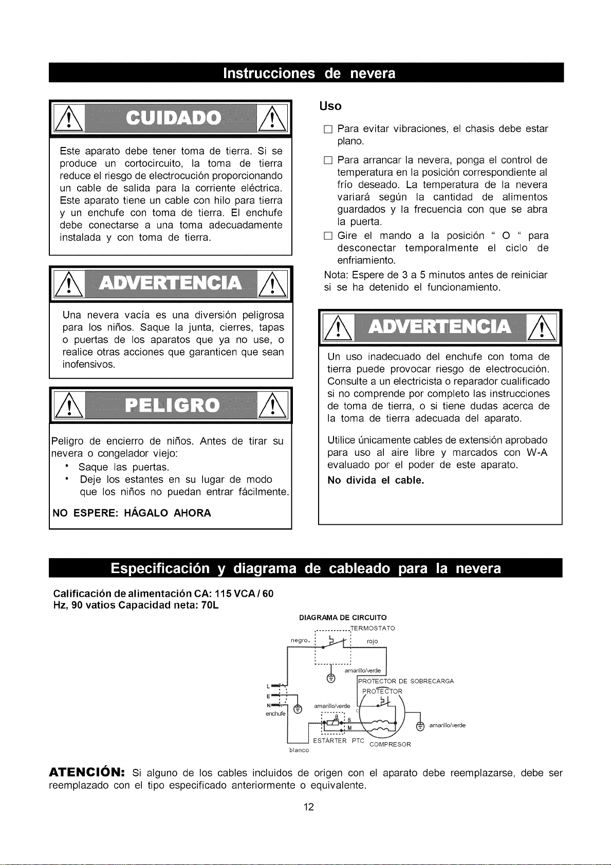
Esteaparatodebetenertomade tierra.Sise
produceun cortocircuito,la toma de tierra
reduceelriesgodeelectrocuci6nproporcionando
un cablede salidaparala corrienteel6ctrica.
Esteaparatotieneuncableconhiloparatierra
y un enchufecontomade tierra.El enchufe
debeconectarsea unatomaadecuadamente
instaladay contomade tierra.
Unaneveravaciaes unadiversi6npeligrosa
paralos nifios.Saquela junta,cierres,tapas
o puertasde los aparatosqueya no use,o
realiceotrasaccionesquegaranticenquesean
inofensivos.
Peligrode encierrode nifios.Antesde tirar su
neverao congeladorviejo:
• Saquelas puertas.
• Dejelosestantesensu lugarde modo
quelos nifiosno puedanentrarfacilmente.
NO ESPERE: HAGALO AHORA
Uso
[] Para evitar vibraciones, el chasis debe estar
piano.
[] Para arrancar la nevera, ponga el control de
temperatura en la posici6n correspondiente al
frio deseado. La temperatura de la nevera
variara segQn la cantidad de alimentos
guardados y la frecuencia con que se abra
la puerta.
[] Gire el mando a la posici6n " O " para
desconectar temporalmente el ciclo de
enfriamiento.
Nota: Espere de 3 a 5 minutos antes de reiniciar
si se ha detenido el funcionamiento.
Un uso inadecuado del enchufe con toma de
tierra puede provocar riesgo de electrocuci6n.
Consulte a un electricista o reparador cualificado
si no comprende por completo las instrucciones
de toma de tierra, o si tiene dudas acerca de
la toma de tierra adecuada del aparato.
Utilice L_nicamentecables de extensi6n aprobado
para uso al aire libre y marcados con W-A
evaluado por el poder de este aparato.
No divida el cable.
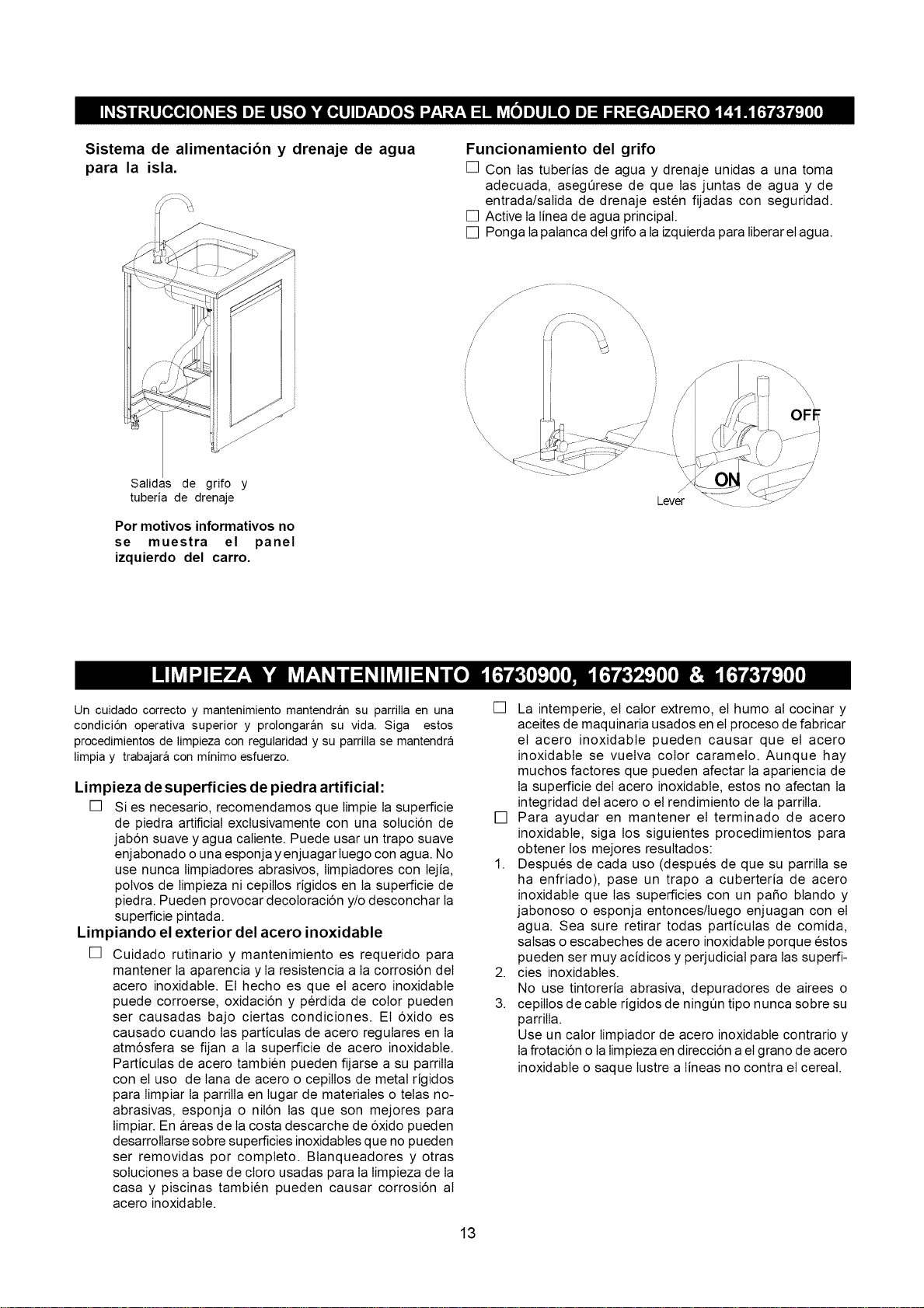
Calificaci6n de alimentaci6n CA: 115 VCA/60
Hz, 90 vatios Capacidad neta: 70L
DIAGRAMA DE CIRCUITO
,. ........... TERMQSTATQ
I '_.3-" IPROTECTOR DE SOBRECARGA
L
I PROT-"_TOR
ench_e I _Jidlufe "-J _....... c
i ; S
amarillo/verde
/
L JESTARTERPTCC_-_PRESOR
blanco
ATENClON: Si alguno de los cables incluidos de origen con el aparato debe reemplazarse, debe ser
reemplazado con el tipo especificado anteriormente o equivalente.
12
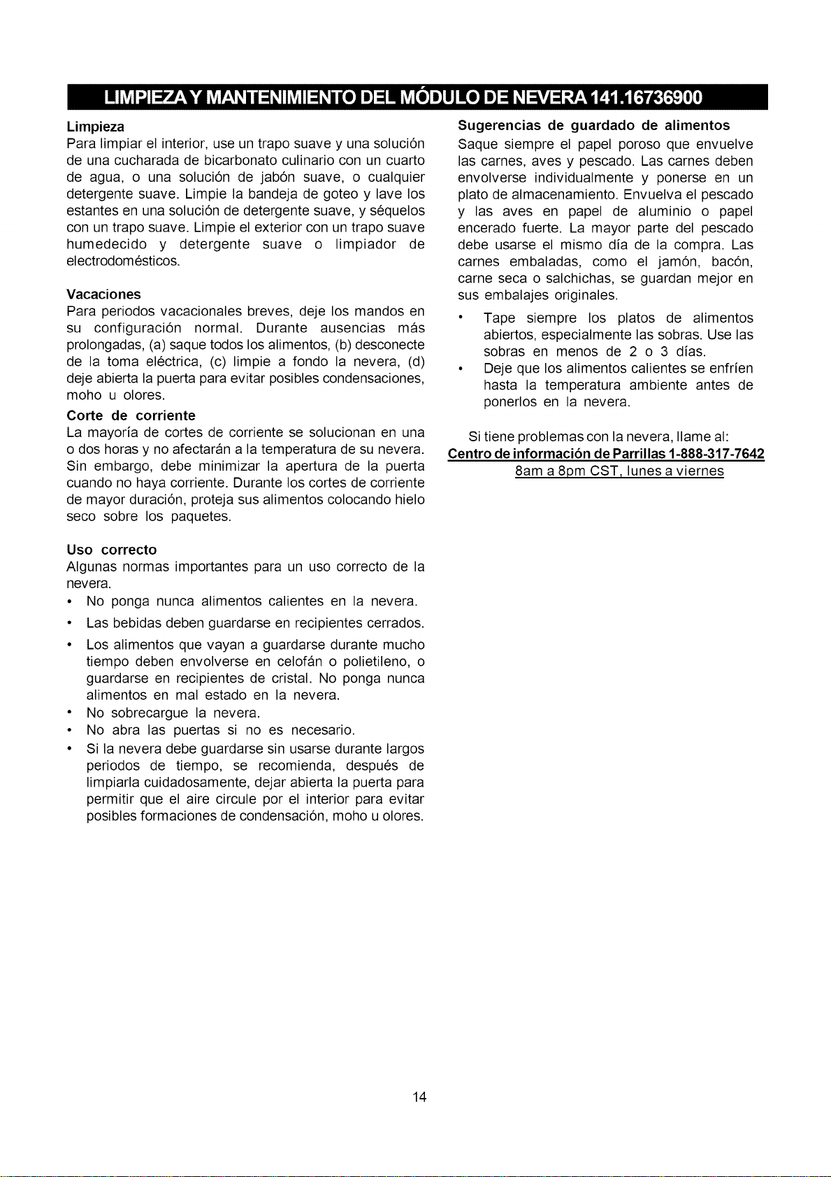
Sistemade alimentaci6ny drenaje de agua
para la isla.
Funcionamiento del grifo
[] Con Ias tuberias de agua y drenaje unidas a una toma
adecuada, asegQrese de que Ias juntas de agua y de
entrada/salida de drenaje esten fijadas con seguridad.
[] Active Ia Iinea de agua principal.
[] Ponga Iapalanca deI gdfo a Iaizquierda para Iiberar eIagua.
/
Salidas de grifo y
tuberia de drenaje
Por motivos informativos no
se muestra el panel
izquierdo del carro.
"\\\
\\\\
Lever
\
I I OFE
II
Un cuidado correcto y mantenimiento mantendran su parrilla en una
condici6n operativa superior y prolongaran su vida. Siga estos
procedimientos de limpieza con regularidad y su parrilla se mantendra
limpia y trabajara con minimo esfuerzo.
Limpieza de superficies de piedra artificial:
[] Si es necesario, recomendamos que Iimpie Iasuperficie
de piedra artificial exclusivamente con una soluci6n de
jab6n suave y agua caIiente. Puede usar un trapo suave
enjabonado o una esponja y enjuagar Iuego con agua. No
use nunca Iimpiadores abrasivos, Iimpiadores con Iejia,
polvos de Iimpieza ni cepilIos rigidos en Ia superficie de
piedra. Pueden provocar decoIoracbn y/o desconchar Ia
superficie pintada.
Limpiando el exterior del acero inoxidable
[] Cuidado rutinario y mantenimiento es requerido para
mantener Ia aparencia y Ia resistencia a Ia corrosi6n deI
acero inoxidabte. El hecho es que el acero inoxidabte
puede corroerse, oxidaci6n y perdida de color pueden
ser causadas bajo ciertas condiciones. El 6xido es
causado cuando Ias particuIas de acero reguIares en Ia
atm6sfera se fijan a la superficie de acero inoxidabte.
Particulas de acero tambien pueden fijarse a su pamlIa
con el uso de Iana de acero o cepilIos de metal rigidos
para Iimpiar Ia parrilIa en Iugar de materiales o telas no-
abrasivas, esponja o niI6n Ias que son mejores para
Iimpiar. En areas de Ia costa descarche de 6xido pueden
desarrollarse sobre superficies inoxidabtes que no pueden
ser removidas por completo. Btanqueadores y otras
soluciones a base de cloro usadas para Ia Iimpieza de Ia
casa y piscinas tambien pueden causar corrosi6n al
acero inoxidabte.
[] La intemperie, el calor extremo, el humo aI cocinar y
aceites de maquinaria usados en el proceso de fabricar
el acero inoxidable pueden causar que el acero
inoxidabte se vuelva color caramelo. Aunque hay
muchos factores que pueden afectar la apariencia de
Ia superficie deI acero inoxidabte, estos no afectan Ia
integridad deI acero o el rendimiento de Ia parrilIa.
[] Para ayudar en mantener el terminado de acero
inoxidabte, siga los siguientes procedimientos para
obtener los mejores resuItados:
1. Despues de cada uso (despues de que su parriIIa se
ha enfriado), pase un trapo a cuberteria de acero
inoxidabte que Ias superficies con un paso btando y
jabonoso o esponja entonces/Iuego enjuagan con el
agua. Sea sure retirar todas particuIas de comida,
saIsas oescabeches de acero inoxidabte porque estos
pueden ser muy acidicos y perjudicial para Ias superfi-
2. cies inoxidabtes.
No use tintoreria abrasiva, depuradores de airees o
3. cepilIos de cable rigidos de ningQn tipo nunca sobre su
parrilIa.
Use un calor Iimpiador de acero inoxidabte contrario y
Iafrotaci6n o IaIimpieza en direcci6n ael grano de acero
inoxidabte o saque lustre a Iineas no contra el cereal.
13
Limpieza
Paralimpiarelinterior,useuntraposuaveyunasoluci6n
deunacucharadadebicarbonatoculinarioconuncuarto
de agua,o unasoluci6nde jab6nsuave,o cualquier
detergentesuave.Limpiela bandejadegoteoy lavelos
estantesenunasoluci6ndedetergentesuave,ys6quelos
conuntraposuave.Limpieelexteriorconuntraposuave
humedecidoy detergente suave o limpiador de
electrodom6sticos.
Vacaciones
Para periodos vacacionales breves, deje los mandos en
su configuraci6n normal. Durante ausencias mas
prolongadas, (a) saque todos los alimentos, (b) desconecte
de la toma el6ctrica, (c) limpie a fondo la nevera, (d)
deje abierta la puerta para evitar posibles condensaciones,
moho u olores.
Corte de corriente
La mayoria de cortes de corriente se solucionan en una
o dos horas y no afectaran a la temperatura de su nevera.
Sin embargo, debe minimizar la apertura de la puerta
cuando no haya corriente. Durante los cortes de corriente
de mayor duraci6n, proteja sus alimentos colocando hielo
seco sobre los paquetes.
Uso correcto
Algunas normas importantes para un uso correcto de la
nevera.
• No ponga nunca alimentos calientes en la nevera.
• Las bebidas deben guardarse en recipientes cerrados.
• Los alimentos que vayan a guardarse durante mucho
tiempo deben envolverse en celofan o polietileno, o
guardarse en recipientes de cristal. No ponga nunca
alimentos en mal estado en la nevera.
• No sobrecargue la nevera.
• No abra las puertas si no es necesario.
• Si la nevera debe guardarse sin usarse durante largos
periodos de tiempo, se recomienda, despues de
limpiarla cuidadosamente, dejar abierta la puerta para
permitir que el aire circule por el interior para evitar
posibles formaciones de condensaci6n, moho u olores.
Sugerencias de guardado de alimentos
Saque siempre el papel poroso que envuelve
las carnes, aves y pescado. Las carnes deben
envolverse individualmente y ponerse en un
plato de almacenamiento. Envuelva el pescado
y las aves en papel de aluminio o papel
encerado fuerte. La mayor parte del pescado
debe usarse el mismo dia de la compra. Las
carnes embaladas, como el jam6n, bac6n,
came seca o salchichas, se guardan mejor en
sus embalajes originales.
• Tape siempre los platos de alimentos
abiertos, especialmente las sobras. Use las
sobras en menos de 2 o 3 dias.
• Deje que los alimentos calientes se enfrien
hasta la temperatura ambiente antes de
ponerlos en la nevera.
Si tiene problemas con la nevera, Ilame al:
Centro de informaci6n de Parrillas 1-888-317-7642
8am a 8pm CST, lunes a viernes
14
Felicitaciones por hacer una compra tan inteligente. Su nuevo producto Kenmore ® esta diseSado y fabricado para tener
aSos de una operacidn confiabte. Pero como todo producto, puede IIegar el dia que requiera reparaciones de vez en cuando.
Eso es cuando se debe tener un Acuerdo de protecci6n de reparos para ahorrarte dinero e irritaci6n.
Esto es Io que es el Acuerdo de protecci6n de reparos* incluye:
[]
[]
[]
[]
[]
Servicio expertos por uno de nuestos 10,000 especialistas en reparos.
Servicio sin Iimites con partes y labor gratis para todas Ias reparaciones que estan cubiertas.
Reemptazo de producto hasta $1,500. d6Iares si el producto cubierto no se puede reparar.
Descuento de 10% deI precio regular de servicio y partes reIacionadas instaladas no cubiertas por el Acuerdo;
tambien, 10% deducido deI precio regular deI cheque de mantenimiento preventivo.
Ayuda rapida por teIefono- nosotros Ia IIamamos SoIuci6n rapida - Ayuda por teIefono de un representante de
Sears. Piense como si nosotros fueramos una "Guia de Uso y Cuidado habtada".
Una vez comprado el Acuerdo de protecci6n de reparos, una simple Ilamada telef6nica es todo Io que necesita hacer para
obtener una citadeI servicio. Usted puede IIamar en cualquier momento dia o noche, o programar una cita para servicio por
el internet.
ElAcuerdo de protecci6n de reparos es una compra Iibre de riesgo. Si usted canceIa por cualquier raz6n durante elperiodo
de garantia deI producto, proveeremos un reemboIso compteto. Puede tambien recibir un reemboIso prorrateado en cualquier
momento despues que el periodo de garantia expira, iCompre su Acuerdo de protecci6n de reparos hoy mismo!
Algunas Iimitaciones y exclusiones son aplicable. Para precios e informaci6n adicional en U.S.A. Ilame 1-800-827-6655.
*La cobertura en Canada varia en algunos articulos. Para obtener mas detalles Ilame a Sears Canada en 1-800-361-6665.
Servicio de instalaci6n de Sears
Para una instaIaci6n profesional de Sears de eIectrodomesticos, abridores de puertas de garajes, calentadores de agua, y
otros importantes aparatos electrodomesticos, en U.S.A. o Canada Ilame al 1-800-4 MY- HOME ®.
15
Your Home
For expert troubleshooting and home solutions advice:
anage
www.managemyhome.com
For repair - in your home - of all major brand appliances,
lawn and garden equipment, or heating and cooling systems,
no matter who made it, no matter who sold it!
For the replacement parts, accessories and
owner's manuals that you need to do-it-yourself.
For Sears professional installation of home appliances
and items like garage door openers and water heaters.
1-800-4-MY-HOME ® (1-800-469-4663)
Call anytime, day or night (U.S.A. and Canada)
www.sears.com www.sears.ca
Our Home
For repair of carry-in items like vacuums, lawn equipment,
and electronics, call anytime for the location of your nearest
Sears Parts & Repair Service Center
1-800-488-1222 (U.S.A.)
www.sears.com
1-800-469-4663 (Canada)
www.sears.ca
To purchase a protection agreement on a product serviced by Sears:
1-800-827-6655 (U.S.A.) 1-800-361-6665 (Canada)
Para pedir servicio de reparaci6n
a domicilio, y para ordenar piezas:
1-888-SU-HOGAR ®
(1-888-784-6427)
Au Canada pour service en fran(_ais:
1-800-LE-FOYER M°
(1-800-533-6937)
www.sears.ca
® Registered Trademark / TMTrademark / SMService Mark of Sears Brands, LLC
® Marca Registrada / TM Marca de F&brica / SMMarca de Servicio de Sears Brands, LLC
MCMarque de commerce / MD Marque depos6e de Sears Brands, LLC @ Sears Brands, LLC