IMPORTANT MANUAL Do Not Throw Away
TM
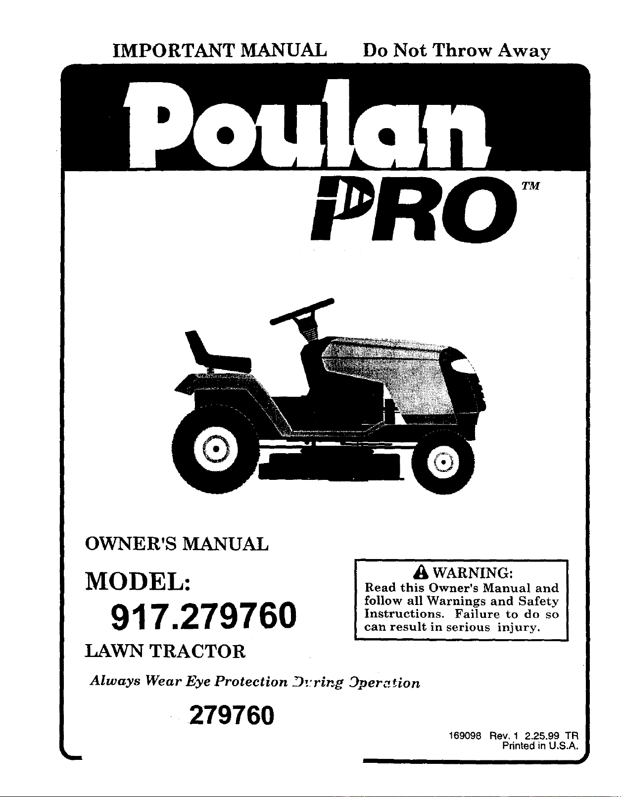
OWNER'S MANUAL
MODEL:
917.279760
a(k WARNING:
Read this Owner's Manual and
follow all Warnings and Safety
Instructions. Failure to do so
can result in serious injury.
LAWN TRACTOR
Always Wear Eye Protection D::ring Dper,.._ion
279760 169098 Rev, 1 2.25.99 TF_
Printed in U.S.A.
SAFETY RULES
Safe Operation Practices for Ride-On Mowers _I,,R
IMPORTANT: THIS CUTTING MACHINE IS CAPABLE OF AMPUTATING HANDS AND FEET AND THROWING OBJECTS.
FAILURE TO OBSERVE THE FOLLOWING SAFETY INSTRUCTIONS COULD RESULT IN SERIOUS INJURY OR DEATH.
I. GENERAL OPERATION
•Read, understand, and follow all instructionsin the manual
and on the machine before starting.
Only allow responsible adults, who are familiar with the
instructions, to operate the machine.
Clear the area of objects such as rocks, toys, wire, etc.,
which could be picked up and thrown by the blade.
Be sure the area isclearof other people before mowing. Stop
machine if anyone enters the area.
Never carry passengers.
Do notmow in reverse unless absolutely necessary. Always
look down and behind before and while backing.
Be aware ofthe mower discharge direction and do not point
it at anyone. Do not operate the mower without either the
entire grass catcher or the guard in place.
Slow down before tumiog.
Never leave a running machine unattended. Always turn off
blades, set parking brake, stop engine, and remove keys
before dismounting.
Turn off blades when not mowing.
•Stop engine before removing grass catcher or unclogging
chute,
•Mow only in daylight or good artificial light.
Do not operate the machine while under the influence of
alcohol or drugs.
Watch for traffic when operating near orcrossing roadways.
Use extra care when Ioad(ng or unloading the machine into
a traiter or truck.
II. SLOPE OPERATION
Slopes are a major factor related to loss-of-control and
tipover accidents, whichcan resultinsevere injuryor death.
All slopes require extra caution. Ifyou cannot back up the
slope or if you feet uneasy on it, do not mow it.
DO:
•Mow up and down slopes, not across.
Remove obstacles such as rocks, tree limbs, etc.
Watch for holes, ruts, or bumps. Uneven terrain could
ovedum the machine. Taffgrass can hide obstac/es.
•Use slow speed. Cheese a low gear so that you willnot have
to stop or shift while on the slope.
•Follow the manufacturer's recommendations for wheel
weights or counterweights to improve stability.
•Use extra care with grass catchers or other attachments.
These can change the stability of the machine.
•Keep all movement on the slopes slow and gradual Do not
make sudden changes in speed or direction.
Avoid starting or stopping on a slope. If tires lose traction,
disengage the blades and proceed slowly straight down the
slope.
DO NOT:
•Donottumonslopesunlessnecessary, andthen,tumslowiy
and gradually downhill, if possible.
•Do notmow near drop-offs, ditches, or embankments, The
mower could suddenly turn over if a wheel is over the edge
of a cliff or ditch, or if an edge caves in.
Do not mow on wet grass. Reduced traction could cause
sliding.
Do not tryto stabilize the machine by putting yourfoot onthe
ground.
•Do not use grass catcher on steep slopes.
lU. CHILDREN
Tragic accidents can occur if the operator is not alert to the
presence of children. Children are often attracted to the
machine and the mowing activity. Never assume that
children will remain where you last saw them.
• Keep children out of the mowing area and under the watchful
care of another responsible adult.
Be alert and turn machine off if children enter the area.
• Before and when backing, look behind and down for small
children.
• Never carry children. They may fall off and be seriously
injured or interfere with safe machine operation.
Never allow children to operate the machine.
Use extra care when approaching blind corners, shrubs,
trees, or other objects that may obscure vision.
IV. SERVICE
•Use extra care inhandlinggasoline and other fuels, They a_'e
flammable and vapors are'explosive.
Use only an approved container.
Never remove gas cap or add fuel with the engine
running. Allow engine to coot before refueling. Do not
smoke.
Never refuel the machine indoors.
Never store the machine or fuel conta{ner inside where
there is an open flame, such as a water heater.
• Never run a machine inside a closed area.
•Keep nuts and bolts, especially blade attachment bolts, tight
and keep equipment in good condition.
• Never tamper with safety devices. Check their proper
operation regularly.
• Keep machine free of grass, leaves, or other debris buifd-up.
Clean oil or fuel spillage. Allow machine to cool before
storing.
• Stop. and inspect the equipment if you strike an object.
Repair, it necessary, before restarting.
• Never make adjustments or repairs with the engine running.
• Grass catchercomponents are subject to wear, damage, and
deterioration, which could expose moving parts or allow
objects to be thrown. Frequently check components and
replace with manufacturer's recommended parts, when nec-
essary.
Mower blades are sharp and can cut. Wrap the blade(s) or
wear gloves, and use extra caution when servicing them.
Check brake operation frequently. Adjust and service as
required.
Look for this symbol to point out im-
portant safety precautions. It means
CAUTION!!! BECOMEALERTH! YOUR
SAFETY IS INVOLVED.
i i ii
CAUTION: Always disconnect spark plug
wire and place wire where itcannot contact
spark plug in order to prevent accidental
starting when setting up, transporting,
adjusting or making repairs:
WARNING A
The engine exhaust from this product con-
tains chemicals known to the State of Califor
nia to cause cancer, birth defects, or other
.reproductive harm.
2
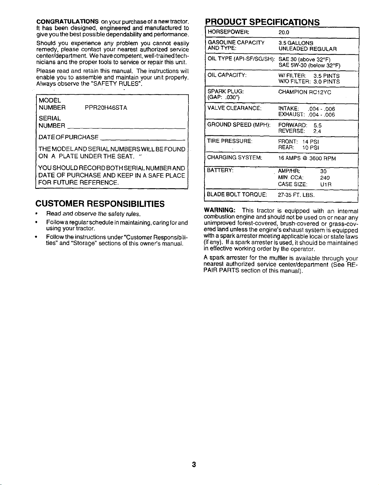
CONGRATULATIONS on your pumhase of a new tractor,
It has been designed, engineered and manufactured to
give you the best possible dependability and performance.
Should you experience any problem you cannot easily
remedy, please contact your nearest authorized service
center/department. We have competent, well-trained tech-
nicians and the proper tools to service or repair this unit.
Please read and retain this manual. The instructions will
enable you to assemble and maintain your unit properly.
Always observe the "SAFETY RULES".
MODEL
NUMBER PPR20H46STA
SERIAL
NUMBER
DATEOFPURCHASE
THE MODELAND SERIAL NUMBERS WILL BE FOUND
ON A PLATE UNDER THE SEAT. "
YOUSHOULDRECORDBOTHSERIALNUMBERAND
DATE OF PURCHASE AND KEEPIN A SAFE PLACE
FOR FUTURE REFERENCE.
CUSTOMER RESPONSIBILITIES
• Read and observe the safety rules.
• Fo!lowa regular schedule in maintaining, caring for and
using your tractor.
• Follow the instructions under"Customer Responsibili-
ties" and "Storage" sections of this owner's manual.
PRODUCT SPECIFICATIONS
HORSEPOWER: 20.0
GASOLINECAPACITY 3.5 GALLONS
AND TYPE: UNLEADED REGULAR
OIL TYPE (API-SF/SG/SH): SAE 30 (above 32OF)
SAE5W-30 (below 32°F)
OIL CAPACITY: W/FILTER: 3.5 PINTS
W/O FILTER: 3.0 PINTS
SPARK PLUG: CHAMPION RC12YC
GAP: .030")
VALVE CLEARANCE: INTAKE: ,004 - .006
EXHAUST: .004 - .006
GROUND SPEED (MPH): FORWARD: 5.5
REVERSE: 2.4
TIRE PRESSURE: FRONT: 14 PSI
REAR: 10 PSi
CHARGING SYSTEM: 16 AMPS @3600 RPM
BA'FI'ERY: AMP/HR: 30
MIN. CCA: 240
CASE SIZE: U1R
iBLADE BOLT TORQUE: 27-35 FT. LBS.
WARNING: This tractor is equipped with an internal
combustion engine and should not be used on or near any
unimproved forest-covered, brush-covered or grass-cov-
ered land unless the engine's exhaust system is equipped
with a spark arrester meeting applicable local or state laws
(if any). If a spark arrester isused, it should be maintained
in effective working order by the operator.
A spark arrester for the muffler is available through your
nearest authorized service center/department (See RE-
PAIR PARTS section of this manual).
3
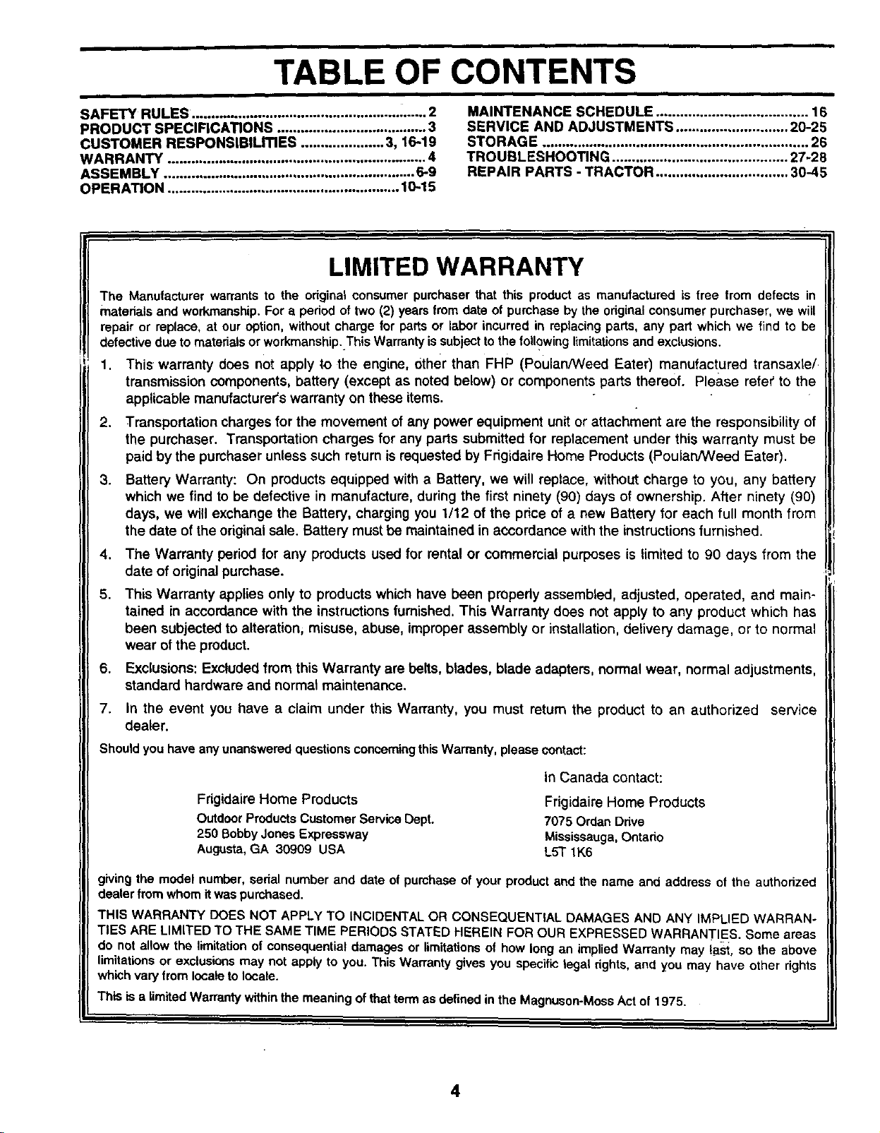
TABLE OF CONTENTS
SAFETY RULES. ................................................... •...... 2
PRODUCT SPECIFICATIONS ...................................... 3
CUSTOMER RESPONSIBILmES ..................... 3, 16-19
WARRANTY .................................................................. 4
ASSEMBLY ................................................................ 6.9
OPERATION ........................................................... 10-15
MAINTENANCE SCHEDULE ...................................... 16
SERVICE AND ADJUSTMENTS ............................ 20-25
STORAGE ................................................................... 26
TROUBLESHOOTING ............................................ 27-28
REPAIR PARTS - TRACTOR ................................. 30-45
LIMITED WARRANTY
The Manufacturerwarrantsto the originalconsumerpumhaserthat this productas manufactured is free from defects in
materialsand workmanship.For a periodof two(2) yearsfrom date of purchaseby theoriginalconsumerpurchaser,we will
repair or replace, at ouroption,withoutchargefor partsor labor incurredin replacingparts,any part which we find to be
defectivedue tomaterials orworkmanship.ThisWarrantyissubjecttothefollowinglimitationsand exclusions•
1. This warranty does not apply to the engine, Other than FHP (Poulan/Weed Eater) manufactured transaxte/
transmission components, battery (except as noted below) or components parts thereof. Please refeT'to the
applicable manufacturer's warranty on these items.
2. Transportation charges for the movement of any power equipment unit or attachment are the responsibility of
the purchaser. Transportation charges for any parts submitted for replacement under this warranty must be
paid by the purchaser unless such return is requested by Frigidaire Home Products (Poulan/Weed Eater).
.Battery Warranty: On products equipped with a Battery, we will replace, without charge to you, any battery
which we find to be defective in manufacture, during the first ninety (90) days of ownership. After ninety (90)
days, we will exchange the Battery, charging you 1/12 of the price of a new Battery for each full month from
the date of the original sale. Battery must be maintained in accordance with the instructions furnished.
4. The Warranty period for any products used for rental or commercial purposes is limited to 90 days from the
date of original purchase.
5. This Warranty applies only to products which have been properly assembled, adjusted, operated, and main-
tained in accordance with the instructions furnished. This Warranty does not apply to any product which has
been subjected to alteration, misuse, abuse, improper assembly or installation, delivery damage, or to normal
wear of the product.
6. Exclusions: Excluded from this Warranty are belts, blades, blade adapters, normal wear, normal adjustments,
standard hardware and normal maintenance.
7. In the event you have a claim under this Warranty, you must return the product to an authorized service
dealer.
Should you have any unanswered questions concerning this Warranty, please contact:
Frigidaire Home Products
Outdoor Products Customer Service Dept.
250 Bobby Jones Expressway
Augusta, GA 30909 USA
In Canada contact:
Frigidaire Home Products
7075 Ordan Drive
Mississauga, Ontario
L5T 1K6
giving the model number, serial number and date of purchase of your product and the name and address of the authorized
dealer from whom itwas purchased.
THIS WARRANTY DOES NOT APPLY TO INCIDENTAL OR CONSEQUENTIAL DAMAGES AND ANY IMPLIED WARRAN-
TIES ARE LIMITED TO THE SAME TIME PERIODS STATED HEREIN FOR OUR EXPRESSED WARRANTIES. Some areas
do not allow the limitation of consequential damages or limitations o! how long an implied Warranty may last, so the above
limitations or exclusions may net apply to you. This Warranty gives you specific legal rights, and you may have other rights
which vary from locale to locale.
This is a limited Warranty within the meaning of that term as defined in the Magnuson-Moss Act of 1975.
4
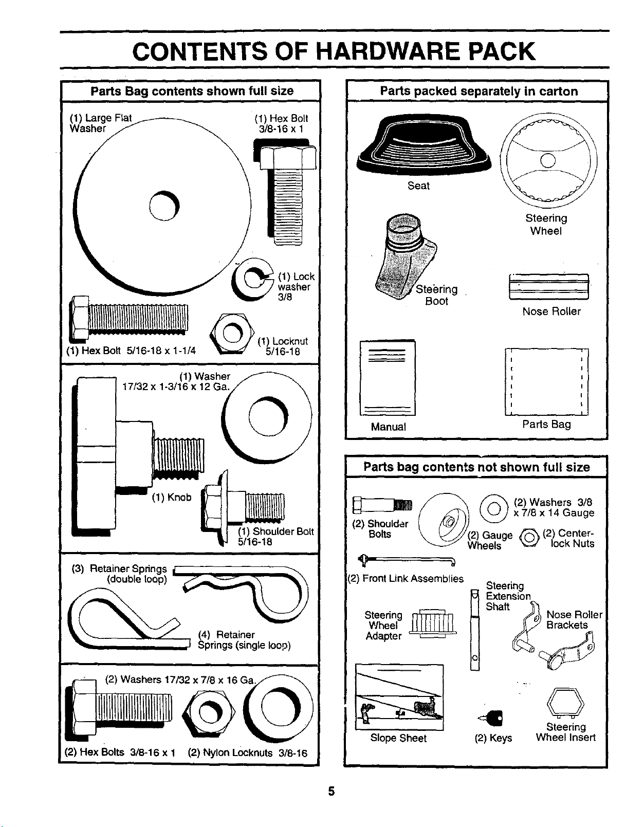
CONTENTS OF HARDWARE PACK
i
Parts Bag contents shown full size
(1) Large Fiat
Washer (1) Hex Bolt
3/8-16 x 1
I
I
I
(1) Hex Bolt 5/16-18 x 1-1/4
(1) Washer
17/32 x 1-3/16 x 12 Ga.
(1) Lock
3/8
(1) Locknut
5/16-18
©
11)Knob
(1) Shoulder Bolt
5/16-18
(3) Retainer Springs j _
(double loop)
_ (4) Retainer
I Springs (single loop)
(2) Nylon Locknuts 3/8-16
i
Parts packed separately in carton
Seat
Steering
Wheel
,0. I- I
Boot Nose Roller
m
Manual Parts Bag
Parts bag contents not shown full size
f--_ _ (2)Washers 3/8
(2_Sheu,dor(_) _ xT,Sx14Gauge
Bolts \ _///f21 Gauae _ (2) Center-
W'heels" _ lock Nuts
12)Front Link Assemblies Steering
Steeringwheel_ Shaft ._ Nose Roller
Adapter
Slope Sheet (2) Keys
©
Steering
Wheel Insert
5
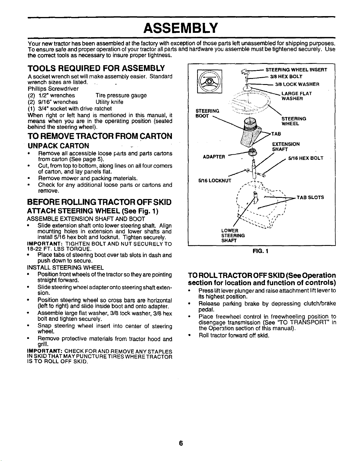
ASSEMBLY
i
Your new tractor has been assembled at the factory withexception of those parts left unassembled for shipping purposes.
To ensure safe and proper operation of your tractor all parts and hardware you assemble must be tightened securely. Use
the correct tools as necessary to insure proper tightness.
TOOLS REQUIRED FOR ASSEMBLY
A socket wrench set will make assembly easier. Standard
wrench sizes are listed. .
Phillips Screwdriver
(2) 1/2" wrenches Tire pressure gauge
(2) 9/16" wrenches Utility knife
(1) 3/4" socket with drive ratchet
When right or left hand is mentioned in this manual, it
means when you are in the operating position (seated
behind the steering wheel).
TO REMOVE TRACTOR FROM CARTON
UNPACK CARTON
•Remove all accessible loose parts and parts cartons
from carton (See page 5).
• Cut, from top to bottom, along lines on all four comers
of carton, and lay panels flat.
•Remove mower and packing materials.
• Check for any additional loose parts or cartons and
remove.
BEFORE ROLLING TRACTOR OFF SKID
ATTACH STEERING WHEEL (See Fig. 1)
ASSEMBLE EXTENSION SHAFT AND BOOT
• Slide extension shaft onto lower steedng shaft. Align
mounting holes in extension and lower shafts and
install 5/16 hex bolt and Iocknut. Tighten securely.
IMPORTANT: TIGHTEN BOLT AND NUT SECURELY TO
18-22 FT. LBS TORQUE.
• Place tabs of steering boot over tab slots in dash and
push down to secure.
INSTALL STEERING WHEEL
• Position front wheels of the tractor so they are pointing
straight forward.
• Slide steering wheel adapter onto steering shaft exten-
sion.
• Position steering wheel so cross bars are horizontal
(left to right) and slide inside boot and onto adapter.
• Assemble large flat washer, 3/8 lock washer, 3/8 hex
bolt and tighten securely.
• Snap steering wheel insert into center of steering
wheel.
• Remove protective materials from tractor hood and
grill.
IMPORTANT: CHECK FOR AND REMOVE ANY STAPLES
IN SKID THAT MAY PUNCTU RETIRES WHERE TRACTOR
IS TO ROLL OFF SKID.
®
STEERING
_--T-'-_ STEERING WHEEL INSERT
________8 HEX BOLT
3/8 LOCK WASHER
_?_ LARGE FLAT
",, WASHER
5/16 HEX BOLT
5/16 LOCKNUT
LOWER
STEERING
SHAFT
FIG. 1
TO ROLLTRACTOR OFF SKID (See Operation
section for location and function of controls)
• Press lift lever plunger and raise attachment lift lever to
its highest position.
• Release parking brake by depressing clutch/brake
pedal.
• Place freewheel control in freewheeling position to
disengage transmission (See "TO TRANSPORT" in
the Oper3tion section of this manual).
• Roll tractor forward off skid.
6
ASSEMBLY
i
HOW TO SET UP YOUR TRACTOR TO ATTACH NOSE ROLLER (See Fig. 4)
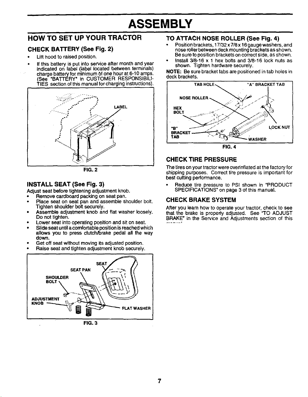
CHECK BATTERY (See Fig. 2)
•Lilt hood to raised position.
•If this battery is put into service after month and year
indicated on label (label located between terminals)
charge battery for _bimum t)f one hour at 6-10 amps.
(See "BA'I-I-ERY" in CUSTOMER RESPONSIBILI-
TIES section of this manual for charging instructions).
LABEL
FIG. 2
INSTALL SEAT (See Fig. 3)
Adjust seat before tightening adjustment knob.
•Remove cardboard packing on seat pan.
• Place seat on seat pan and assemble shoulder bolt.
Tighten shoulder bolt securely.
•Assemble adjustment knob and flat washer loosely.
Do not tighten.
•Lower seat intooperating position and sit on seat.
•Slide seat untilacomfodable positionisreached which
allows you to press clutch/brake pedal all the way
down.
•Get off seat without moving its adjusted position.
•Raise seat and tighten adjustment knob securely.
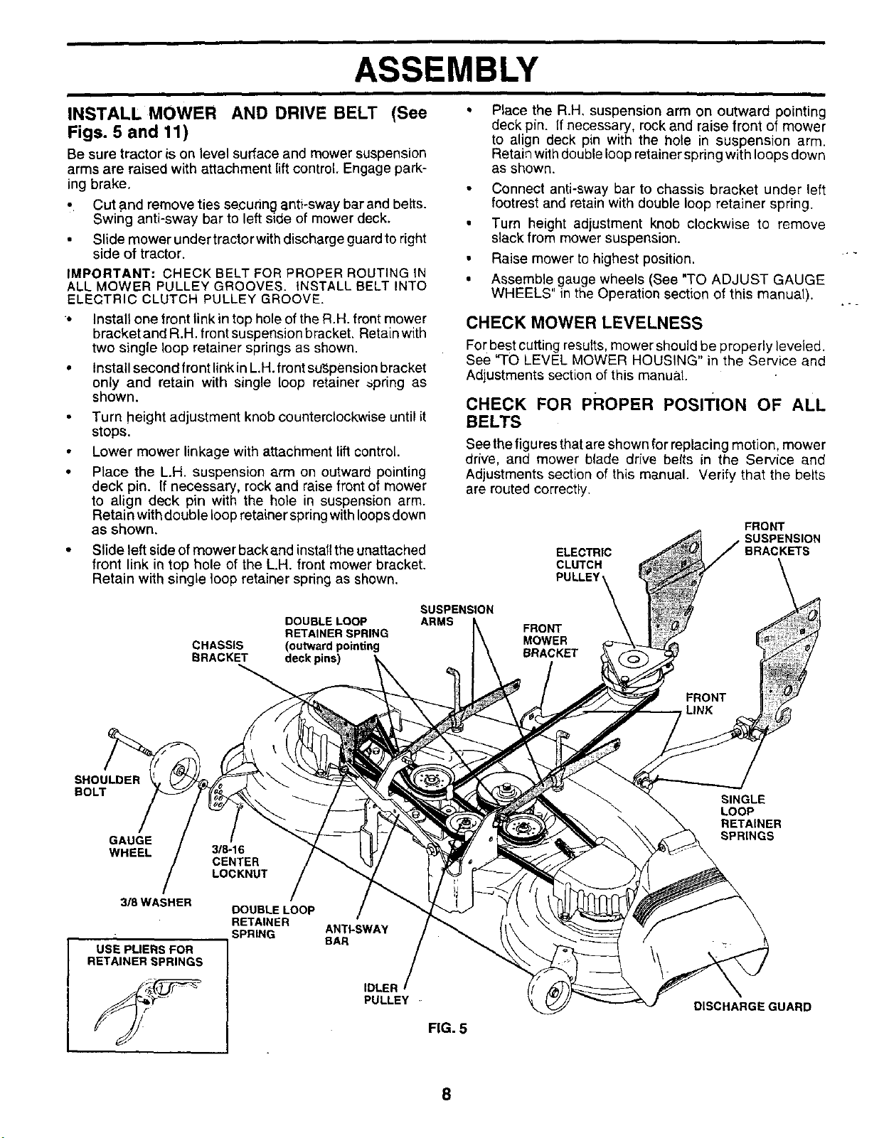
• Position brackets, 17/32 x 7/8 x16 gauge washers, and
nose roUerbetween deck mounting brackets as shown.
Be sure to position brackets on correct side, as shown.
• Install 3/8-16 x 1 hex bolts and 3/8-16 lock nuts as
shown. Tighten hardware securely.
NOTE: Be sure bracket tabs are positioned in tab holes in
deck brackets.
"A"BRACKETTAB
NOSE ROLLER_ -._.__
HEX
BOLT
"B" LOCK NUT
TAB WASHER
FIG. 4
CHECK TIRE PRESSURE
The tires on your tractor were ovefinflated at the factory for
shipping purposes. Correct tire pressure is important for
best cutting performance.
• Reduce tire pressure to PSI shown in "PRODUCT
SPECIFICATIONS" on page 3 of this manual.
CHECK BRAKE SYSTEM
After you leam how to operate your tractor, check to see
that the brake is properly adjusted. See "TO ADJUST
BRAKE" in the Service and Adjustments section of this
....... i
SEAT
SEAT PAN
SHOULDER
ADJUSTMENT
KNOB FLAT WASHER
FIG. 3
7
ASSEMBLY
Q
INSTALL MOWER AND DRIVE BELT (See
Figs. 5 and 11)
Be sure tractor is on level surface and mower suspension
arms are raised with attachment liftcontrol. Engage park-
ing brake.
•Cut and remove ties securing anti-sway bar and belts.
Swing anti-sway bar to left side of mower deck.
•Slide mower under tractor with discharge guard to right
side of tractor.
IMPORTANT: CHECK BELT FOR PROPER ROUTING IN
ALL MOWER PULLEY GROOVES. INSTALL BELT INTO
ELECTRIC CLUTCH PULLEY GROOVE.
* Install one front link in top hole of the R.H. front mower
bracket and R.H. front suspension bracket, Retain with
two single loop retainer springs as shown.
• Install second front link in L.H. front sut3pension bracket
only and retain with single loop retainer _pring as
shown.
Turn height adjustment knob counterclockwise until it
stops.
Lower mower linkage with attachment lift control.
Place the L.H. suspension arm on outward pointing
deck pin. If necessary, rock and raise front of mower
to align deck pin with the hole in suspension arm.
Retain with double loop retainer spring with loops down
as shown.
• Slide left side of mower back and installtheunattached
front link in top hole of the L.H. front mower bracket.
Retain with single loop retainer spring as shown.
Place the R.H, suspension arm on outward pointing
deck pin. If necessary, rock and raise front of mower
to align deck pin with the hole in suspension arm.
Retain with double loop retainer spring with loops down
as shown.
• Connect anti-sway bar to chassis bracket under left
footrest and retain with double loop retainer spring.
• Turn height adjustment knob clockwise to remove
slack from mower suspension.
• Raise mower to highest position.
• Assemble gauge wheels (See "TO ADJUST GAUGE
WHEELS' in the Operation section of this manual).
CHECK MOWER LEVELNESS
For best cutting results, mower should be properly leveled.
See "TO LEVEL MOWER HOUSING" in the Service and
Adjustments section of this manual.
CHECK FOR PROPER PosITION OF ALL
BELTS
See thefigures that are shown for replacing motion, mower
ddve, and mower blade drive belts in the Service and
Adjustments section of this manual. Verify that the belts
are routed correctly.
ELECTRIC
CLUTCH
PULLEY
FRONT
BRACKETS
DOUBLE LOOP
RETAINER SPRING
CHASSIS (outward pointing
BRACKET deck pins)
SUSPENSION
ARMS FRONT
MOWER
BRACKET
SHOULDER
BOLT
GAUGE
WHEEL
318 WASHER
USE PLIERS FOR
RETAINER SPRINGS
318-16
CENTER
LOCKNUT
DOUBLE LOOP
RETAINER
SPRING ANTI*SWAY
BAR
IDLER
PULLEY
FIG. 5
SINGLE
LOOP
RETAINER
SPRINGS
DISCHARGE GUARD
8
ASSEMBLY
JCHECKLIS T
BEFORE YOU OPERATE AND ENJOY YOUR NEW
TRACTOR, WE WISH TO ASSURE THAT YOU RECEIVE
THE BEST PERFORMANCE AND SATISFACTION FROM
THIS QUALITY PRODUCT.
PLEASE REVIEW THE'FOLLOWING CHECKLIST:
•/All assembly instructions have been completed.
,/ No remaining loose parts in carton.
,/ Batteryis properly prepared and charged. (Minimum
1 hour at 6 amps).
,/ Seat is adjusted comfortably and tightened securely.
,I Alltires are properly inflated. (For shipping purposes,
the tires were ovednflated at the factory).
,/ Be sure mower deck is properly le"ve]ed side-to-side/
front-to-rear for best cutting results. (Tires must be
properly inflated for leveling).
,/ Check mower and drive belts. Be sure they are routed
propedy around pulleys and inside all belt keepers.
,/ Checkwiring. See that all connections are still secure
and wires are propedy clamped.
,/ Before driving tractor, be sure freewheel control is in
drive position.
WHILE LEARNING HOW TO USE YOUR TRACTOR, PAY
EXTRA ATTENTION TO THE FOLL OWING IMPORTANT
ITEMS:
,/ Engine oil is at proper level.
,/ Fuel tank is _led with fresh, clean, regular unleaded
gasoline.
,/ Become familiar with all controls - their location and
function. Operate them before you start the engine.
J Be sure brake system is in safe operating condition.
•/It is important to purge the transmission before operat-
ing your tractor for the first time. Follow proper starting
and transmission purging instructions (See "TO START
ENGINE" and "PURGE TRANSMISSION" in the Op-
eration section of this manual).
9
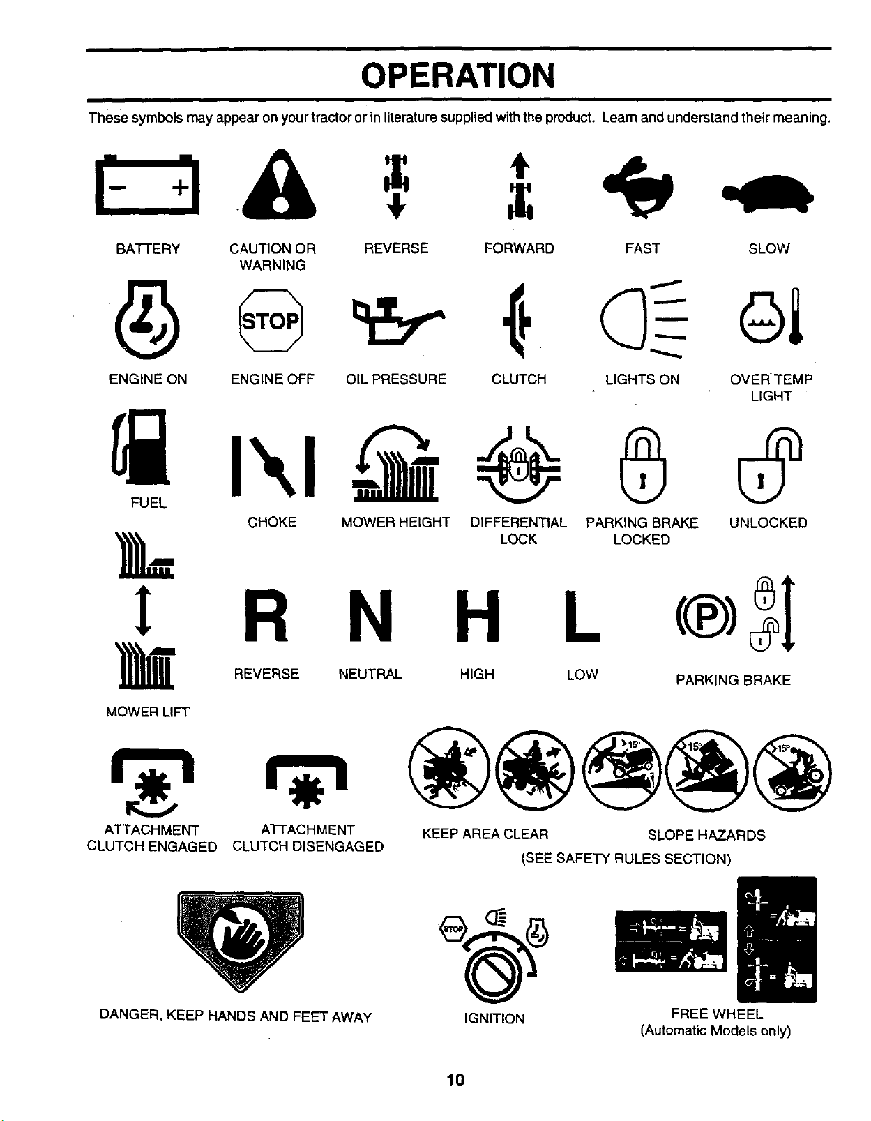
OPERATION
These symbols may appear on yourtractor or in literature supplied withthe product. Learn and understand their meaning.
BATI'ERY CAUTION OR REVERSE FORWARD
WARNING
ENGINE ON ENGINE OFF OIL PRESSURE CLUTCH
FAST SLOW
LIGHTS ON OVERTEMP
LIGHT
FUEL CHOKE MOWER HEIGHT DIFFERENTIAL PARKING BRAKE
LOCK LOCKED
! R N H L
REVERSE NEUTRAL HIGH LOW
MOWER LIFT
UNLOCKED
PARKING BRAKE
ATTACHMENT
CLUTCH ENGAGED A'I-I'ACH MENT
CLUTCH DISENGAGED KEEP AREA CLEAR SLOPE HAZARDS
(SEE SAFETY RULES SECTION)
DANGER, KEEP HANDS AND FEET AWAY IGNITION FREE WHEEL
(Automatic Models only)
10
OPERATION
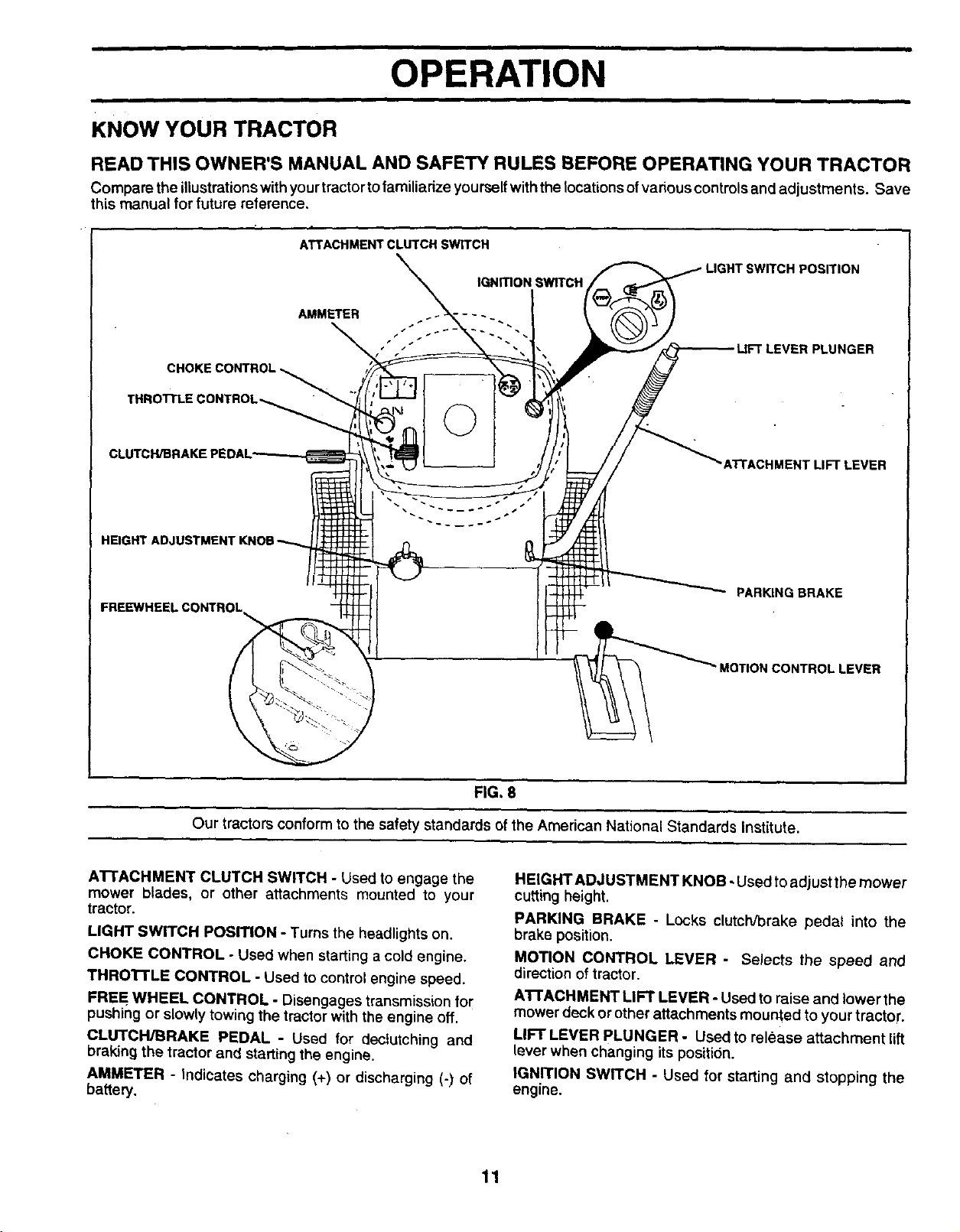
KNOW YOUR TRACTOR
READ THIS OWNER'S MANUAL AND SAFETY RULES BEFORE OPERATING YOUR TRACTOR
Compare the illustrations with your tractor to familiadze yourself with the locations of vadous controls and adjustments. Save
this manual for future reference,
ATTACHMENT CLUTCH SWITCH
POSITION
IGNITION SWITCH
AMMETER
CHOKE CONTROL _
THROTTLE CONTROL_ ©
LUNGER
LEVER
FREEWHEEL CONTROL PARKING BRAKE
•MOTION CONTROL LEVER
FIG, 8
Our tractors conform to the safety standards of the American National Standards Institute.
AI-rACHMENT CLUTCH SWITCH -Used to engage the
mower blades, or other attachments mounted to your
tractor.
LIGHT SWITCH PosmoN -Turns the headlights on.
CHOKE CONTROL -Used when starting a cold engine.
THROI-rLE CONTROL -Used to control engine speed.
FREE WHEEL CONTROL -Disengages transmission for
pushing or slowly towing the tractor with the engine off.
CLUTCH/BRAKE PEDAL -Used for dectutching and
braking the tractor and starting the engine•
AMMETER -Indicates charging (+) or discharging (-) of
battery.
HEIGHT ADJUSTMENT KNOB -Used to adjust the mower
cutting height.
PARKING BRAKE - Locks clutch/brake pedal into the
brake position.
MOTION CONTROL LEVER - Selects the speed and
direction of tractor.
A'rrACHMENT LIFT LEVER -Used to raise and lower the
mower deck or other attachments mounted to your tractor.
LIFT LEVER PLUNGER - Used to release attachment lift
lever when changing its position.
IGNITION SWITCH - Used for starting and stopping the
engine.
11
OPERATION
Ii
The operation of any tractor can result in foreign objects thrown into the eyes, which can I
result in severe eye damage. Always wear safety giesses or eye shields while operating I
your tractor or performing any adjustments or repairs. We recommend a wide vision safety
mask over spectacles or standard safety giaeses.
HOW TO USE YOUR TRACTOR
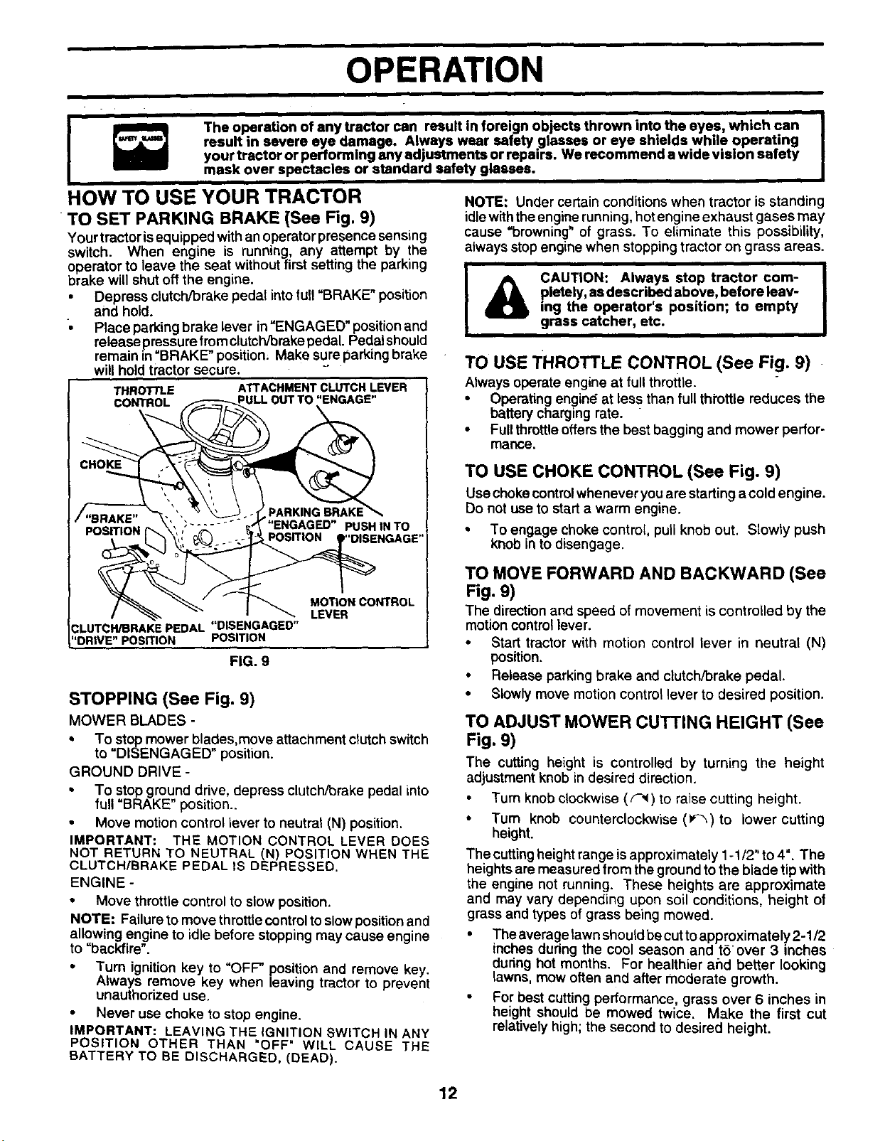
TO SET PARKING BRAKE (See Fig. 9)
Your tractorisequipped with an operatorpresence sensing
switch. When engine is running, any attempt by the
operator to leave the seat without first setting the parking
brake will shut off the engine.
•Depress clutch/brake pedal into full"BRAKE" position
and hold.
•Place parking brake lever in"ENGAGED" position and
releasepressure from clutch/Drake pedal. Pedal should
remain m =BRAKE"position. Make sure parking brake
will hold tractor secure.
T.RO .E A AC..ENTCLUTCH,EVE.
cONTROL F"_---_ ULL OUT TO"ENGAGE"
,/"BRAKE" "" _'" _ '_'" PARKINGBRAKE_.
POSITION [" \'' ;....... _' "ENGAGED" PUSHINTO
_ _NGAGE'
" I _ MOTIONCONTROL
i_- LEVER
.3LUTCH/BRAKEPEDAL"DISENGAGEO"
i"DRIVE"POSITION POSITION
FIG. 9
STOPPING (See Fig. 9)
MOWER BLADES -
• To stop mower blades,move attachment clutchswitch
to "DISENGAGED" position.
GROUND DRIVE -
• To stop ground drive, depress clutch/Drake pedal into
full "BRAKE" position..
• Move motion control lever to neutral (N) position.
IMPORTANT: THE MOTION CONTROL LEVER DOES
NOT RETURN TO NEUTRAL (N) POSITION WHEN THE
CLUTCH/BRAKE PEDAL IS DEPRESSED.
ENGINE -
• Move throttle control to slow position.
NOTE: Failure to move throttle control to slow position and
allowing engine to idle before stopping may cause engine
to "backfire".
• Turn ignition key to "OFF" position and remove key.
Always remove key when leaving tractor to prevent
unauthorized use.
• Never use choke to stop engine.
IMPORTANT: LEAVING THE IGNITION SWITCH IN ANY
POSITION OTHER THAN "OFF" WILL CAUSE THE
BATTERY TO BE DISCHARGED, (DEAD).
NOTE: Under certain conditions when tractor is standing
idle with the engine running, hot engine exhaust gases may
cause "browning" of grass. To eliminate this possibility,
always stop engine when stopping tractor on grass areas.
ii
I & CAUTION: Always stop tractor com-
pletely, as described above, before leav-
ing the operator's position; to empty
grass catcher, etc.
TO USE THROTTLE CONTROL (See Fig. 9)
Always operate engine at fullthrottle.
•Operating engin_ at less than fullthrottle reduces the
battery charging rate.
•Fullthrottle offersthe best bagging and mower peffor-
malice,
TO USE CHOKE CONTROL (See Fig. 9)
Use choke controlwhenever you are starting acold engine.
Do not use to startawarm engine.
• To engage choke control, pull knob out. Slowly push
knob in to disengage.
TO MOVE FORWARD AND BACKWARD (See
Fig. 9)
The direction and speed of movement is controlled by the
motion control lever.
• Start tractor with motion control lever in neutral (N)
position.
• Release parking brake and clutch/Drake pedal.
•Slowly move motion control lever to desired position.
TO ADJUST MOWER CUTTING HEIGHT (See
Fig. 9)
The cutting height is controlled by turning the height
adjustment knob in desired direction.
Turn knob clockwise (F_) to raise cutting height.
•Turn knob counterclockwise (t,_) to lower cutting
height.
The cuttingheightrange isapproximately 1-1/2" to4". The
heights are measured from the ground tothe blade tip with
the engine not running. These heights are approximate
and may vary depending upon soil conditions, height of
grass and types of grass being mowed.
•The average lawn shoukfbecuttoapproximately 2-1/2
inches during the cool season and t6 over 3 inches
during hot months. For healthier and better looking
lawns, mow often and after moderate growth.
For best cutting performance, grass over 6inches in
height should be mowed twice. Make the first cut
relatively high; the second to desired height.
12
OPERATION
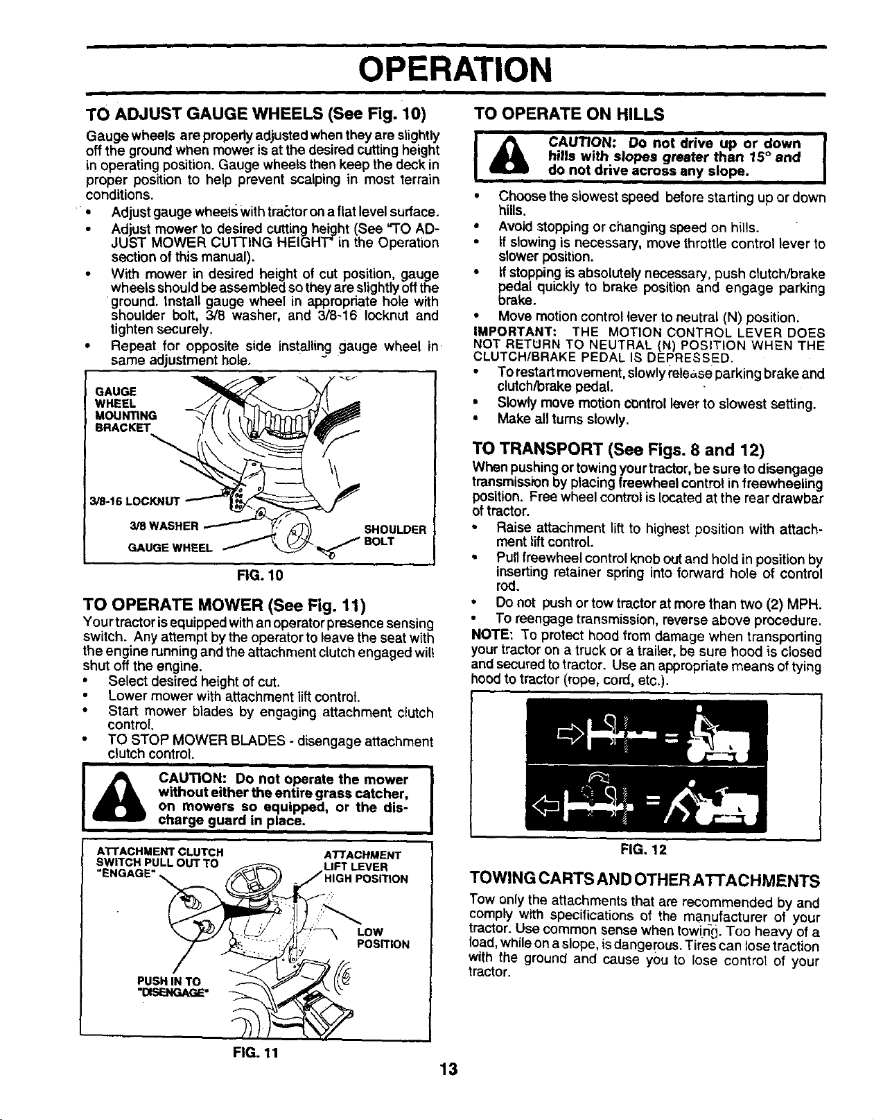
TO ADJUST GAUGE WHEELS (See Fig. 10) TO OPERATE ON HILLS
Gauge wheels are properly adjusted when they are slightly
off the ground when mower isat the desired cutting height
in operating position. Gauge wheels then keep the deck in
proper position to help prevent scalping in most terrain
conditions.
•Adjust gauge wheels withtram:toton a flat level surface.
•Adjust mower to desired cutting height (See "TO AD-
JUST MOWER CU'['[ING HEIGHT'in the Operation
section of this manual).
•With mower in desired height of cut position, gauge
wheels should be assembled sothey are slightlyoffthe
ground. Install gauge wheel in appropriate hole with
shoulder bolt, 3/8 washer, and 3/8-16 Iocknut and
tighten securely.
•Repeat for opposite side installing gauge wheel in
same adjustment hole.
GAUGE
WHEEL
MOUN_NG
BRACKET
SHOULDER
FIG. 10
TO OPERATE MOWER (See Fig. 11)
Your tractorisequipped with an operator presence sensing
switch. Any attempt bythe operator to leave the seat with
the engine runningand theattachment clutchengaged will
shut off the engine.
•Select desired height of cut.
•Lower mower with attachment lift control.
• Start mower blades by engaging attachment clutch
control.
•TO STOP MOWER BLADES - disengage attachment
clutch control.
i
l_ CAUTION: Do not operate the mower
without either the entire grass catcher,
on mowers so equipped, or the dis-
charge guard in place.
ATTACHMENT CLUTCH ATTACHMENT
FIG. 11 13
I,_ CAUTION: DO not drive up or down
411 hills with slopes greater than 15° and
do not drive across any slope.
• Choose the slowest speed before starting up or down
hills.
•Avoid stopping or changing speed on hills.
•If slowing is necessary, move throttle control lever to
slower position.
• If stopping is absolutely necessary, push clutch/brake
_emdalquickly to brake position end engage parking
ke.
• Move motion control lever to neutral (N) position.
IMPORTANT: THE MOTION CONTROL LEVER DOES
NOT RETURN TO NEUTRAL (N) POSITION WHEN THE
CLUTCH/BRAKE PEDAL IS DEPRESSED.
• To restart movement, slowly release parking brake and
clutch/brake pedal.
•Slowly move motion control lever to slowest setting.
• Make all turns slowly.
TO TRANSPORT (See Figs. 8 and 12)
When pushing ortowing your tractor, be sure todisengage
transmission by placing freewheel control in freewheeling
position. Free wheel controlis located at the rear drawbar
of tractor.
•Raise attachment lift to highest position with attach-
ment liftcontrol.
•Pullfreewheel controlknob out and hold in position by
inserting retainer spdng into forward hole of control
rod.
•Do not push or tow tractor at more than two (2) MPH.
•To reengage transmission, reverse above procedure.
NOTE: To protect hood from damage when transporting
yourtractor on a truck or a trailer, be sure hood is closed
and secured totractor. Use an appropriate means of tying
hood to tractor (rope, cord, etc.).
FIG, 12
TOWING CARTS AND OTHER ATTACHMENTS
Tow only the attachments that are recommended by and
comply with specifications of the manufacturer of your
tractor. Use common sense when towing. Too heavy of a
load, whileon a slope, is dangerous. Tires can lose traction
with the ground and cause you to lose controt of your
tractor,
OPERATION
BEFORE STARTING THE ENGINE
CHECK ENGINE OIL LEVEL (See Fig. 18)
•The engine inyour tractor has been shipped, from the
factory, already filled with summer weight eil.
Check engine oil with tractor o.nlevel ground.
• Remove oil filt cap/dipstick and wipe clean, reinsert the
dipstick and screw cap tight, wait for a few seconds,
remove and read oil level. If necessary, add oil until
"FULL" mark on dipstick is reached. Do not overfill.
• For cold weather operation you should change oil for
easier starting (See "OIL VISCOSITY CHART" in the
Customer Responsibilities section of this manual).
• To change engine oil, see the Customer Responsibili-
ties section in this manual.
ADD GASOLINE
• Fill fuel tank. Use fresh, clean, regular unleaded
gasoline with a minimum of 87 octane. (Use of leaded
gasoline will increase carbon and lead oxide deposits
and reduce valve life). Do not mix oil with gasoline.
Purchase fuel in quantities that can be used within 30
days to assure fuel freshness.
IMPORTANT: WHEN OPERATING IN TEMPERATURES
BELOW 32°F(0°C), USE FRESH, CLEAN WINTER GRADE
GASOLINE TO HELP INSURE GOOD COLD WEATHER
STARTING.
WARNING: Experience indicates that alcohol blended
fuels (called gasohol or using ethanol or methanol) can
attract moisture which leads to separation and formation of
acids during storage. Acidic gas can damage the fuel
system of an engine while in storage. To avoid engine
problems, the fuel system should be emptied before stor-
age of 30 days or longer. Drain the gas tank, start the
engine and let it run until the fuel lines and carburetor are
empty. Use fresh fuel next season. See Storage Instruc-
tions for additional information. Never use engine or
carburetor cleaner products in the fuel tank or permanent
damage may occur.
filler neck. Do not overfill. Wipe off any
spilled oil or fuel. Do not store, spill or
use gasoline near an open flame.
TO START ENGINE (See Fig. 9)
When starting the engine for the first time or if the engine
has ru'_out of fuel, it will take extra cranking time to move
fuel from the tank to the engine.
Be sure freewheel control is in the transmission en-
gaged position.
• Sit on seat in operating position, depress clutch/brake
pedal and set parking brake.
Place motion control lever in neutral (N) position.
•Move attachment clutch to "DISENGAGED" position.
•Move throttle controlto fast position
• Pull choke control out for a cold engine start attempt.
For a warm engine start attempt the choke control may
not be needed.
NOTE:Before starting, read the warm and cold starting
procedures below.
•Insert key into ignitionand turn key clockwise to"STARI"
position and release key as soon as'engine starts. Do
not run starter continuously for more than fifteen sec-
onds per minute. If the engine does not start after
several attempts, push choke control in, wait a few
minutes and try again. If engine still does not start, putt
the choke control out and retry.
WARM WEATHER STARTING (50°F and above)
• When engine starts, slowly push choke control in until
the engine begins to run smoothly. If the engine starts
to run roughly, pull the choke control out slightly for a
few seconds and then continue to push the control in
slowly.
•The attachments and ground drive can now be used. If
the engine does not accept the load, restart the engine
and allow it to warm up for one minute using the choke
as described above.
COLD WEATHER STARTING (50° F and below)
• When engine starts, slowly push choke control in until
the engine begins to run smoothly. Continue to push
the choke control in small steps allowing the engine to
accept small changes in speed and load, until the
choke control is fully in. If the engine starts to run
roughly, pull the choke control out slightly for a few
seconds and then continue to push the control in
slowly. This may require an engine warm-up period
from several seconds to several minutes, depending
on the temperature.
AUTOMATIC TRANSMISSION WARM UP
• Before driving the unit in cold weather, the transmis-
sion should be warmed up as follows:
• Be sure the tractor is on level ground.
Place the motion control lever in neutral.
Release the parking brake and let the clutch/brake
slowly return to operating position.
• Allow one minute for transmission to warm up. This
can be done during the engine warm up period.
The attachments can be used during the engine warm-
up period after the transmission has been warmed up
and may require the choke control be pulled out slightly.
NOTE: If at a high altitude (above 3000 feet) or in cold
temperatures (below 32 F) the carburetor fuel mixture may
need to be adjusted for best engine performance. See "TO
ADJUST CARBURETOR" in the Service and Adjustments
section of this manual.
14
OPERATION
PURGE TRANSMISSION
I _ CAUTION: Neverengageordisengage I
freewheel lever while the engine is run-
ning.
To ensure proper operation and performance, itis recom-
mended that the transmfSsion be'purged before operating
tractor for the first time. This procedure will remove any
trapped air inside the transmission which may have devel-
oped during shipping of your tractor.
IMPORTANT: SHOULD YOUR TRANSMISSION
REQUIRE REMOVAL FOR SERVICE OR
REPLACEMENT, IT SHOULD BE PURGED AFTER
REINSTALLATION BEFORE OPERATING THE
TRACTOR.
• Place tractor safely on level surface with engine off and
parking brake set....
•Disengage transmission by placing freewheel control
in freewheeling position (See "TO TRANSPORT' in
this section of manual).
• Sitting inthe tractor seat, start engine. After the engine
is running, move throttle control to slow position. With
motion control lever in neutral (N) position, slowly
disengage clutclVbrake pedal.
• Move motion control lever to full forward position and
hold for five (5) seconds. Move lever to full reverse
position and hold for five (5) seconds. Repeat this
procedure three (3) times.
NOTE: During this procedure there will be no movement of
drive wheels. The air isbeing removed from hydraulic drive
system.
• Move motion control lever to neutral (N) position. Shut-
off engine and set parking brake.
• Engage transmission by placing freewheel control in
driving position (See "TO TRANSPORT' in this section
of manual).
• Sitting inthe tractor seat, start engine. After the engine
is running, move throttle control to half (1/2) speed.
With motion control lever in neutral (N) position, slowly
disengage clutch/brake pedal.
• Slowly move motion control lever forward, after the
tractor moves approximately five (5) feet, slowly move
motion control lever to reverse position. After the
tractor moves approximately five (5) feet return the
motion control lever to the neutral (N) position. Repeat
this procedure with the motion control lever three (3)
times.
• Your tractor is now purged and now ready for normal
operation.
MOWING TIPS
•Tire chainscannot be used when the mower housing is
attached to tractor.
•Mower should be properly leveled for best mowing
performance. See "TO LEVEL MOWER HOUSING" in
the Service and Adjustments section of this manual.
• The left hand side of mower should be used for trim-
ming.
Drive so that clippings are discharged onto the area
that has been cut. Have the cut area to the right of the
machine. This wit( result in a more even distribution of
clippings and more uniform cutting.
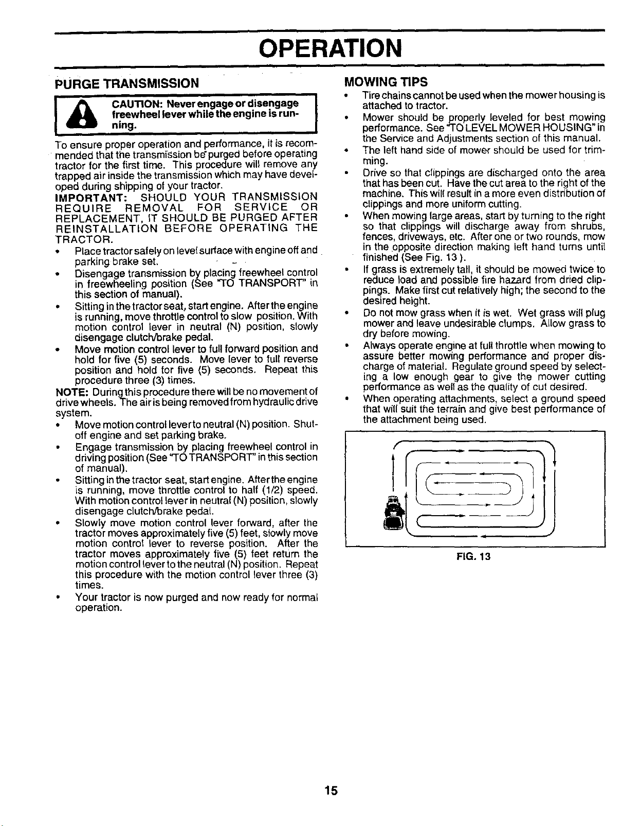
When mowing large areas, start by turning to the right
so that clippings will discharge away from shrubs,
fences, driveways, etc. After one or two rounds, mow
in the opposite direction making left hand turns until
finished (See Fig. 13 ).
• If grass is extremely tall, it should be mowed twice to
reduce load and possible fire hazard from dried clip-
pings. Make first cut relatively high; the second to the
desired height.
• Do not mow grass when it iswet. Wet grass will plug
mower and leave undesirable clumps. Allow grass to
dry before mowing.
• Always operate engine at full throttle when mowing to
assure better mowing performance and proper dis-
charge of material. Regulate ground speed by select-
ing a low enough gear to give the mower cutting
performance as welt as the quality of cut desired.
• When operating attachments, select a ground speed
that will suit the terrain and give best performance of
the attachment being used.
f
•J
FIG. 13
15
CUSTOMER RESPONSIBILITIES
Check Brake Operatio_ _1
Check Tire Pressure .
Check Operator Presence and
T Interlock Systems
Check for Loose Fasteners V#7 t##
Lubrication Chart V#
T Check Battery Level
R cl_ Battery end Terminals if
Check TransaxleCooling _r
_just B'ade B't(s) T_si°_ _1_:
Adjust Moron Drive Belt(s) Tension
Check Engine Oil Lev_ VI/
Change Engine Oil _3 If
Clean Air Filter _1_2
Clean Air Screen _2
Inspect Muffler/Spark Arraster l#l
Replace Oil Filter (If equipped) _:2
EN Clean Engine Cooling Fins
Replace Spark Plug _1
Replace Air F_ter Paper Cadddge V/2
Replace Fuel Filter
1 - Ch_mge more Otten whertope_fcng under a heaw load or in high ambiaot tempe_ture_, 5 - ff eq_pped withadjustable system.
2 - Servk:e more oifan when opmaltng Lndirty o¢dusty condiifons.
3-If equipped withOilfi_er, changeoil e_ery 50 hours.
4 - Rep_ce I_ades mo_e onen when mowing insandy soil.
GENERAL RECOMMENDATIONS
The warranty on this tractor does notcover itemsthat have
been subjected to operator abuse or negligence. To
receive full value from the warranty, operator must main-
tain tractor as instructed in this manual.
Some adjustments will need to be made periodically to
properly maintain your tractor,
All adjustments in the Service and Adjustments section of
this manual should be checked at least once each season.
•Once a year you should replace the spark plug clean
or replace air filter, and check blades and belts for
wear. A new spark plug and clean air filter assure
proper air-fuel mixture and help your engine run better
and last longer.
6-Not requirl_ if equipped wi_ tnaiotenanc_free banes.
7 - Tighten front axle p_ot bolt to 35 If,-Ibs, maximum,
E_onotovedigoten.
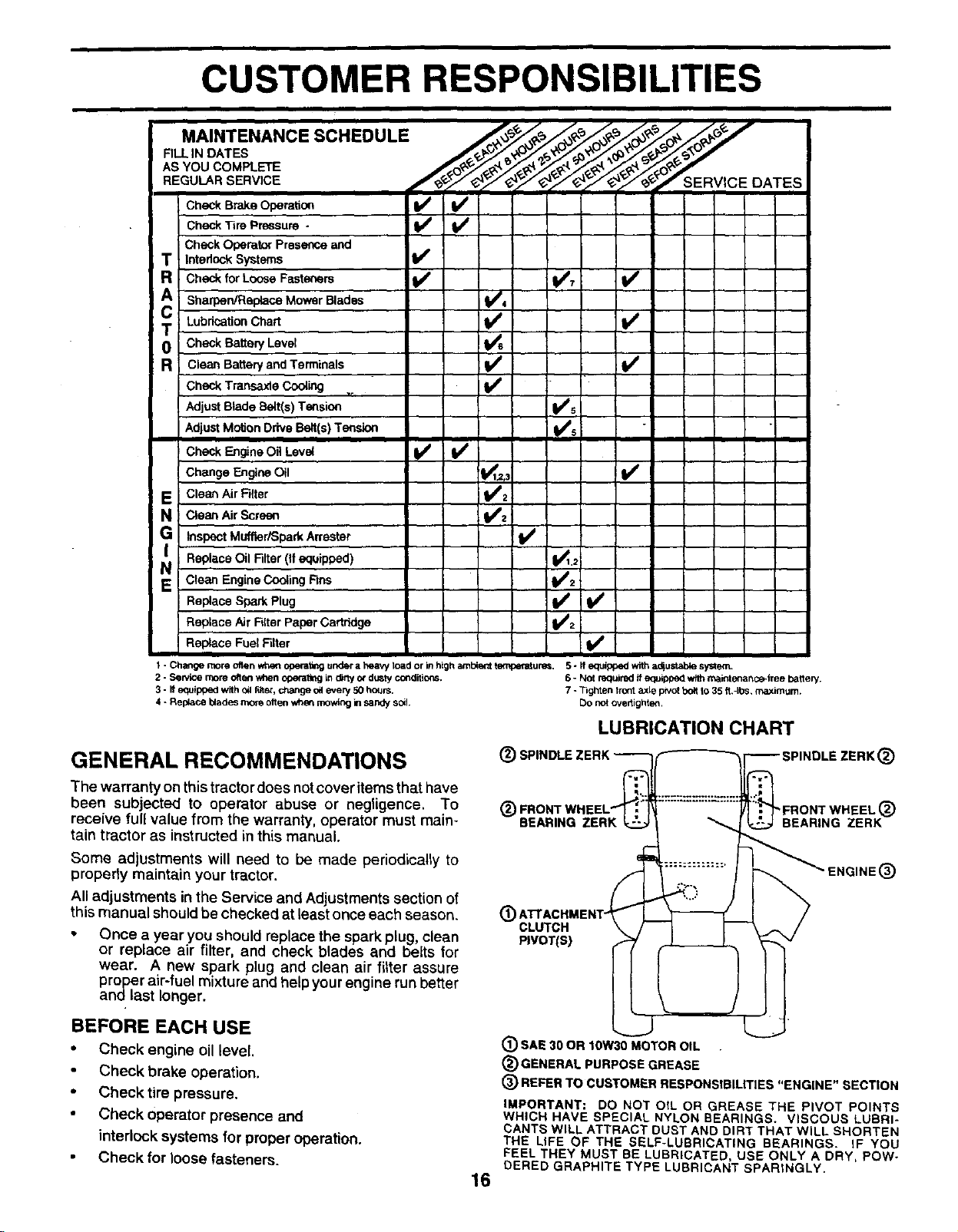
LUBRICATION CHART
(_ SPINDLE Z ;PINDLE ZERK _)
(_ " FRONT WHEEL (_)
BEARING ZERK BEARING ZERK
ENGINE(_)
®CLUTCH
PIVOT[S)
BEFORE EACH USE
•Check engine oil level.
Check brake operation.
•Check tire pressure.
Check operator presence and
interlock systems for proper operation.
Check for loose fasteners. 16
(_) SAE 30 OR 10W30 MOTOR OIL
(_) GENERAL PURPOSE GREASE
(_) REFER TO CUSTOMER RESPONSIBILITIES "ENGINE" SECTION
IMPORTANT: DO NOT OIL OR GREASE THE PIVOT POINTS
WHICH HAVE SPECIAL NYLON BEARINGS. VISCOUS LUBRI-
CANTS WILL ATTRACT DUST AND DIRT THAT WILL SHORTEN
THE LIFE OF THE SELF-LUBRICATING BEARINGS. IF YOU
FEEL THEY MUST BE LUBRICATED, USE ONLY A DRY, POW-
DERED GRAPHITE TYPE LUBRICANT SPARINGLY.
lU
CUSTOMER RESPONSIBILITIES
TRACTOR
Always observe safety rules when performing any mainte-
nance.
BRAKE OPERATION
If tractor requires more than six (6) feet stopping distance
at high speed in highest gear, then brake must be adjusted.
(See "TO ADJUST BRAKE" in the Service and Adjust-
ments section of this manual).
TIRES
•Maintain proper air pressure in al_tires (See "PROD-
UCT SPECIFICATIONS" section of this manual).
• Keep tires free of gasoline, oil. or insect control chemi-
cals which can harm rubber.
Avoid stumps, stones, deep ruts, sharp objects and'
other hazards that may cause tire damage.
NOTE: To seal tire punctures and prevent fiat tires due to
stow leaks, tire sealant may be purchased from your local
parts dealer. Tire sealant also prevents tire dry rot and
corrosion.
OPERATOR PRESENCE SYSTEM
Be sure operator presence and interlock systems are
working properly. If your tractor does not function as
described, repair the problem immediately.
•The engine should not start unless the clutch/brake
pedal isfully depressed and attachement clutch control
ISin the disengaged position,
•When the engine is running, any attempt bythe opera-
tor to leave the seat without first setting the parking
brake should shut off the engine.
•When the engine is running and the attachment clutch
is engaged, any attempt by the operator to leave the
seat should shut off the engine.
•The attachment clutchshould never operate unless the
operator is in the seat.
BLADE CARE
For best results mower blades must be kept sharp. Re-
place bent or damaged blades.
BLADE REMOVAL (See Fig, 15)
• Raise mower to highest position to allow access to
blades.
• Remove hexbolt, lockwasher and flat washer securing
blade.
• Install new or resharpened blade with trailing edge up
towards deck as shown.
TRAILING EDGE UP
BLADE CENTER
HOLE
MANDREL
ASSEMBLY
LOCK WASHER\ STAR
_" HEX BOLT (GRADE 8)
*A GRADE 8 HEAT TREATED BOLT CAN BE
IDENTIFIED BY SIX UNES ON THE BOLT HEAD.
IMPORTANT: TO ENSURE PROPER ASSEMBLY,
CENTER HOLE IN BLADE MUST ALIGN WITH STAR ON
MANDREL ASSEMBLY.
• Reassembl_ hex boil, lock washer and flat washer in
exact order as shown.
• Tighten bolt securely (30-35 Ft. Lbs. torque).
tMPOR3"ANT: BLA_3E BOLT IS GRA[3E 8 HEAT TREATED.
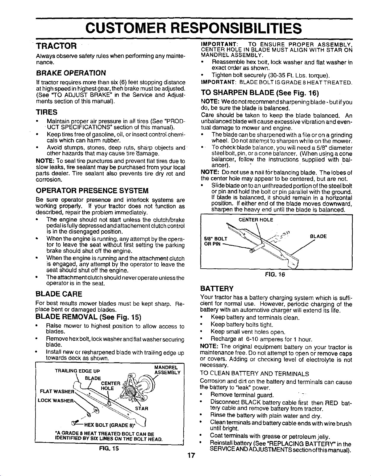
TO SHARPEN BLADE (See Fig. 16)
NOTE: We donot recommer_d sharpening blade - but ifyou
do, be sure the blade is balanced.
Care should be taken to keep the blade balanced. An
unbalar_ced b_adewit_cause excessive vibration and even-
tual damage to mower and engine.
• The blade can be sharpened with a file or on a grinding
wheel Do not attempt to sharpen while on the mower,
•To chE_,ckblade balance, you will need a 5/8" diameter
steel bolt, pin, or a cone balancer. (When using a cone
balancar, follow the instructions supplied with bal-
ancer).
NOTE: Do not use a nail for balancing blade. The lobes of
the center hole may appear to be centered, but are not,
• Slide blade on to an unthreaded portion of the steel bolt
or pin and hold the bolt or pin parallel with the ground.
If blade is balanced, it should remain in a horizontal
position. If either end of the blade moves downward,
sharpen the heavy end until the blade is balanced.
CENTER HOLE
5/8" BOLT
OR PIN
FIG. 16
BA'B'ERY
Your tractor has a battery charging system which is suffi-
cient for normal use. However, periodic charging of the
battery with an automotive charger will extend its life.
•Keep battery and terminals clean.
• Keep battery bolts tight.
Keep small vent holes open,
• Recharge at 6-10 amperes for 1 hour.
NOTE: The original equipment battery on your tractor is
maintenance free. Do not attempt to open or remove caps
or covers, Adding or checking _eve_of electrolyte is not
necessary.
TO CLEAN BA'_-ERY AND TERMINALS
Corrosion and dirt on the battery and terminals can cause
the battery to "leak" power.
Remove terminal guard. " -
• Disconnect BLACK battery cable iirst then RED bat-
tery cable and remove battery from tractor.
• Rinse the battery with plain water and dry.
• Clean terminals and battery cable ends with wire brush
until bright.
• Coat terminals with grease or petroleum jelly.
• Reinstall battery (See "REPLACING BAI-r ERY" in the
SERVICE AND ADJUSTMENTS section of this manual).RG. 15 17
CUSTOMER RESPONSIBILITIES
i
V-BELTS
Check V-belts for deterioration and wear after 100 hoursof
operation and replace if necessary. The belts are not
adjustable. Replace belts if they begin to slipfrom wear.
TRANSAXLE COOLING
The fan and cooling tins gf transmission should be kept
clean to assure proper cooling.
Do not attempt to clean fan or transmission while engine is
running or while the transmission is hot.
• Inspect cooling fan to be sure fan blades are intact and
clean.
Inspect cooling fins for dirt, grass clippings and other
matedals, To prevent damage to seals, do not use
compressed air or high pressure sprayer to clean
cooling fins.
TRANSAXLE PUMP FLUID ""
The transaxle was sealed at the factory and fluid mainte-
nance isnotrequired for the life of the transaxle. Should the
transaxle ever leak or require servicing, contact your near-
est authorized service centerldepartment.
ENGINE
LUBRICATION
Only use high quality detergent oil rated with API service
classification SF, SG, or SH. Select the oil'sSAE viscosity
grade according to your expected operating temperature.
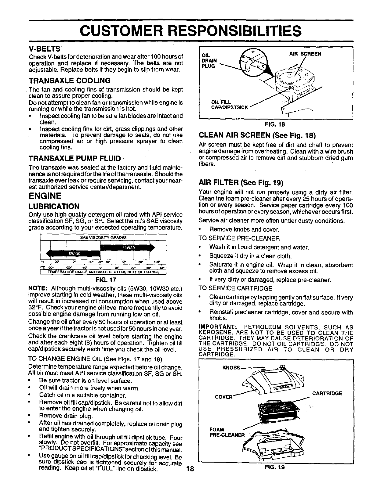
OIL [_ _A AIR SCREEN
,%,,-
OIL RLL / :-"_""
CAP,OIPSTSICK /
FIG. 18
CLEAN AIR SCREEN (See Fig. 18)
Air screen must be kept free of dirt and chaff to prevent
engine damage fromoverheating. Clean with awire brush
or compressed air to remove dirtand stubborn dried gum
fibers.
AIR FILTER(See Fig. 19)
Your engine will not run propedy using a dirty air filter.
Clean the foam pre-cleaner after every 25 hours of opera-
tion or every season. Service paper cartridge every 100
hoursofoperation or every season, whichever occurs first.
Service air cleaner more often under dusty conditions.
• Remove knobsand cover.
SAE VISCOSITY GRADES
FIG. 17
NOTE: Although multi-viscosity oils (5W30, 10W30 etc.)
improve starting in cold weather, these multi-viscosity oils
will result in increased oilconsumption when used above
32°F. Check your engine oillevel more frequently to avoid
possible engine damage from running low on oil.
Change the oil after every 50 hours of operation or at least
once a year i!the tractor isnot used for50 hoursinone year.
Check the crankcase oil level before starting the engine
and after each eight (8) hours of operation. Tighten oil fill
cap/dipstick securely each time you check the oil level.
TO CHANGE ENGINE OIL (See Figs. 17 and 18)
Determine temperature range expected before oil change.
All oil must meet API service classification SF, SG or SH.
Be sure tractor is on level surface.
Oil will drain more freely when warm.
• Catch oil in a suitable container.
Remove oil fill cap/dipstick. Be careful not to allow dirt
to enter the engine when changing oil.
•Remove drain plug.
After oil has drained completely, replace oil drain plug
and tighten securely.
Refill engine with oil through o f IId pst ck tube. Pour
sowly. uo not overfill. For approximate capacity see
"PRODUCT SPECIFICATIONS" section ofthis manual.
•Usegaugeonoilfillcap/dipstickforchecking eve Be
sure dipst ck cap is tightened securely for accurate
reading. Keep oil at =FULL" line on dipstick.
TO SERVICE PRE-CLEANER
•Wash it in liquid detergent and water.
• Squeeze it dry in a clean cloth.
• Saturate it in engine oil. Wrap it in clean, absorbent
cloth and squeeze to remove excess oil.
• If very dirty or damaged, replace pre-cleaner.
TO SERVICE CARTRIDGE
• Clean cartridge by tappinggently onflat surface. Ifvery
dirty or damaged, replace cartridge.
•Reinstall precleaner cartridge, cover and secure with
knobs.
IMPORTANT: PETROLEUM SOLVENTS, SUCH AS
KEROSENE, ARE NOT TO BE USED TO CLEAN THE
CARTRIDGE, THEY MAY CAUSE DETERIORATION OF
THE CARTRIDGE, DO NOT OIL CARTRIDGE, DO NOT
USE PRESSURIZED AIR TO CLEAN OR DRY
CARTRIDGE,
KNOBS
COVER_ CARTRIDGE
18 FIG. 19
CUSTOMER RESPONSIBILITIES
CLEAN AIR INTAKE/COOLING AREAS
To insure proper cooling, make sure the grass screen,
cooling fins, and other external surfaces of the engine are
kept clean at all times.
Every 100 hours of operation (more often under extremely
dusty, dirty conditions), remove the blower housing and
other Coolingshrouds. Clean the'cooling fins and external
surfaces as necessary. Make sure the cooling shrouds are
reinstalled.
NOTE: Operating the engine witha blocked grass screen,
dirty or plugged cooling fins, and/or cooling shrouds re-
moved will cause engine damage due to overheating.
MUFFLER
nspect and replace corroded muffler and spark an'ester (if
equipped) as itcould create a fire hazard and/or damage.
SPARK PLUGS
Replace spark plugs at the beginning of each mowing
season or after every 100 hours of operation, whichever
occurs first. Spark plug type and gap setting are shown in
"PRODUCT SPECIFICATIONS" section of this manual.
ENGINE OIL FILTER
Replace the engine oilfilterevery season or every other oil
change if the tractor is used more than 100 hours in one
year.
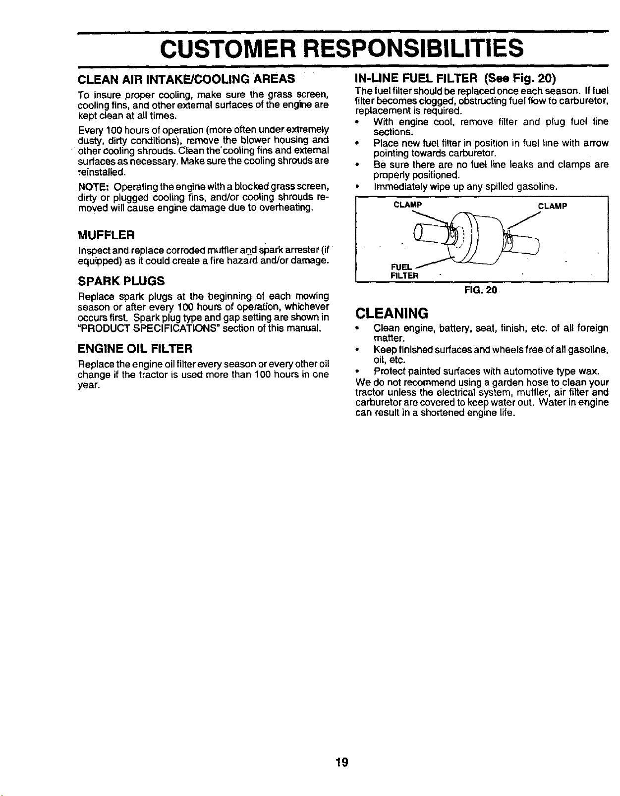
IN-LINE FUEL FILTER (See Fig. 20)
The fuel filtershouldbe replaced once each season. Iffuel
filter becomes clogged, obstructingfuel flow to carburetor,
replacement is required.
•With engine cool, remove filter and plug fuel line
sections.
• Place new fuel filter in position in fuel line with arrow
pointing towards carburetor.
•Be sure there are no fuel line leaks and clamps are
properly positioned.
• Immediately wipe up any spilled gasoline.
CLAMP CLAMP
RLTER FIG. 20
CLEANING
• Clean engine, battery, seat, finish, etc. of all foreign
matter.
•Keep finished surfaces and wheels free ofall gasoline,
oil, etc.
•Protect painted surfaces with automotive type wax.
We do not recommend using a garden hose to clean your
tractor unless the electrical system, muffler, air filter and
carburetor are covered tokeep water out. Water in engine
can result in ashortened engine life.
19
i
SERVICE AND ADJUSTMENTS
i
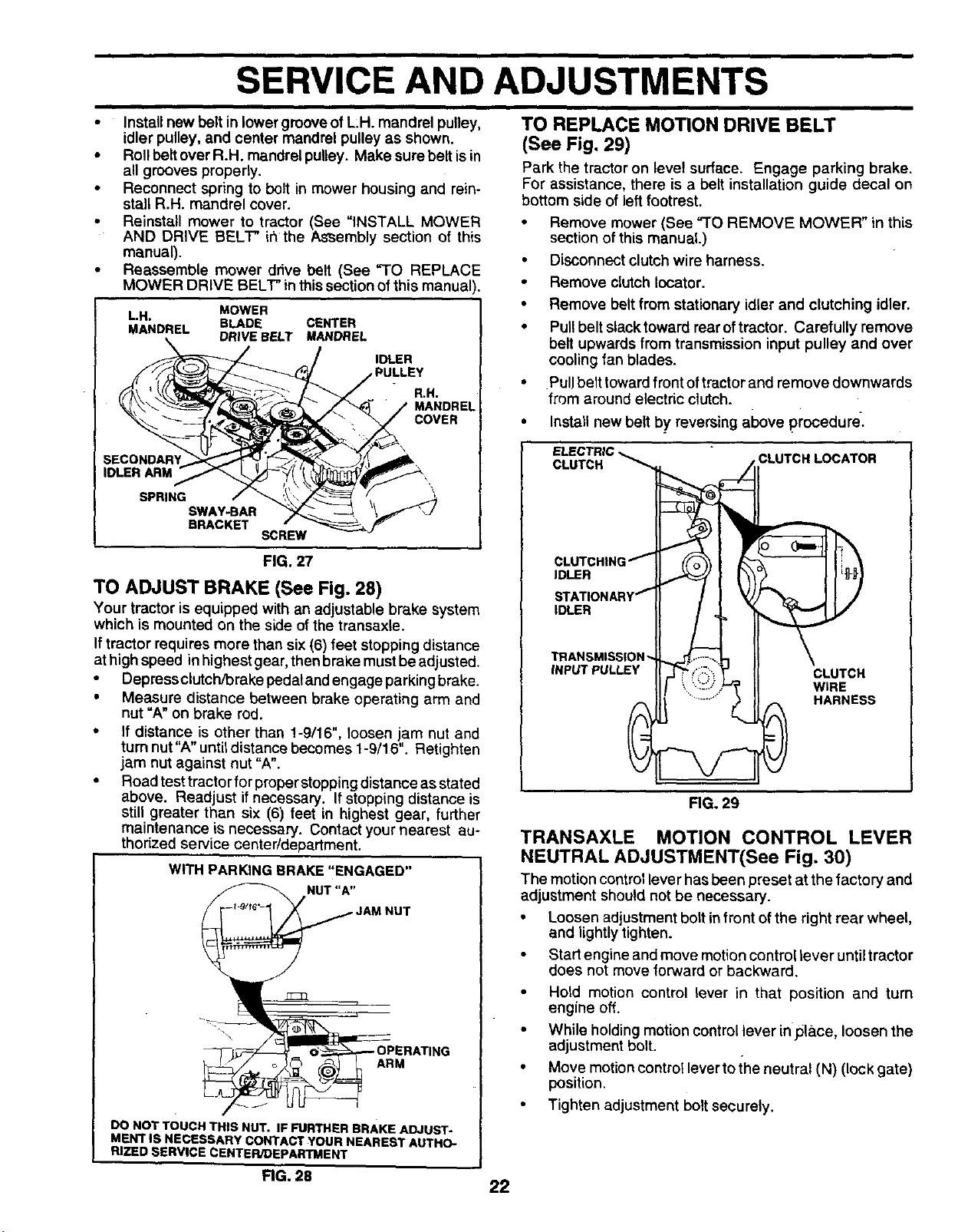
• Install new belt in lower groove of L:H. mandrel pulley,
idler pulley, and center mandrel pulley as shown.
•Roll belt over R.H. mandrel pulley. Make sure belt isin
all grooves properly.
•Reconnect spring to bolt in mower housing and rein-
stall R.H. mandrel cover.
•Reinstall mower to tractor (See "INSTALL MOWER
AND DRIVE BELl" ir_the AsSembly section of this
manual).
•Reassemble mower drive belt (See "TO REPLACE
MOWER DRIVE BELT" in thissection ofthis manual
L.H. MOWER
MANDREL BLADE CENTER
DRIVE BELT MANDREL
IDLER
,PULLEY
R.H.
MANDRE
SECONDARY
IDLER ARM
SPRING SWAY-BAR
BRACKET SCREW
FIG. 27
TO ADJUST BRAKE (See Fig. 28)
Your tractor is equipped with an adjustable brake system
which is mounted on the s_le of the transaxle.
If tractor requires more than six(6) feet stopping distance
at high speed inhighest gear, then brake mustbeadjusted.
•Depress clutch/orake pedat andengage parkingbrake.
•Measure distance between brake operating arm and
nut =A"on brake rod.
• If distance is other than !-9/16", loosen jam nut and
turn nut "A" until distance becomes 1-9/16". Retighten
jam nut against nut "A".
• Road test tractor for preper stopping distance as stated
above. Readjust if necessary. If stopping distance is
still greater than six (6) feet in highest gear, further
maintenance is necessary. Contact your nearest au-
thorized service centeddepartment.
WITH PARKING BRAKE "ENGAGED"
ARM
DO NOT TOUCH THIS NUT. IF FURTHER BRAKE ADJUST-
MENT IS NECESSARY CONTACT¥OUR NEAREST AUTHO-
RIZED SERVICE CENTER/DEPARTMENT
i
TO REPLACE MOTION DRIVE BELT
(See Fig. 29)
Park the tractor on level surface. Engage parking brake.
For assistance, there is abelt installation guide decal on
bottom side of left footrest.
• Remove mower (See "TO REMOVE MOWER" in this
section of this manual.)
•Disconnect clutch wire harness.
•Remove clutch Iocator.
•Remove belt from stationary idler and clutching idler.
•Pull belt slacktoward rear oftractor. Carefully remove
belt upwards from transmission input pulley and over
cooling fan blades.
•Pullbelt towardfront oftractor and remove downwards
from around electric clutch.
• Install new belt by reversing above procedure.
ELECTRIC
CLUTCH _CLUTCH LOCATOR
CLUTCHING f
IDLER
STATIONARY _"
IDLER
TRANSMISSION "-
INPUT PULLEY CLUTCH
WIRE
HARNESS
FIG. 29
TRANSAXLE MOTION CONTROL LEVER
NEUTRAL ADJUSTMENT(See Fig. 30)
The motioncontrol lever has been preset at the factory and
adjustment should not be necessary.
• Loosen adjustment bolt in front of the right rear wheel,
and lightly tighten.
• Start engine and move motion control lever until tractor
does not move forward or backward.
• Hold motion control lever in that position and turn
engine off.
•While holding motion controllever inplace, loosen the
adjustment bolt.
•Move motion control lever toihe neutral (N) (lock gate)
position.
•Tighten adjustment boltsecurely.
FIG. 28 22
SERVICE AND ADJUSTMENTS
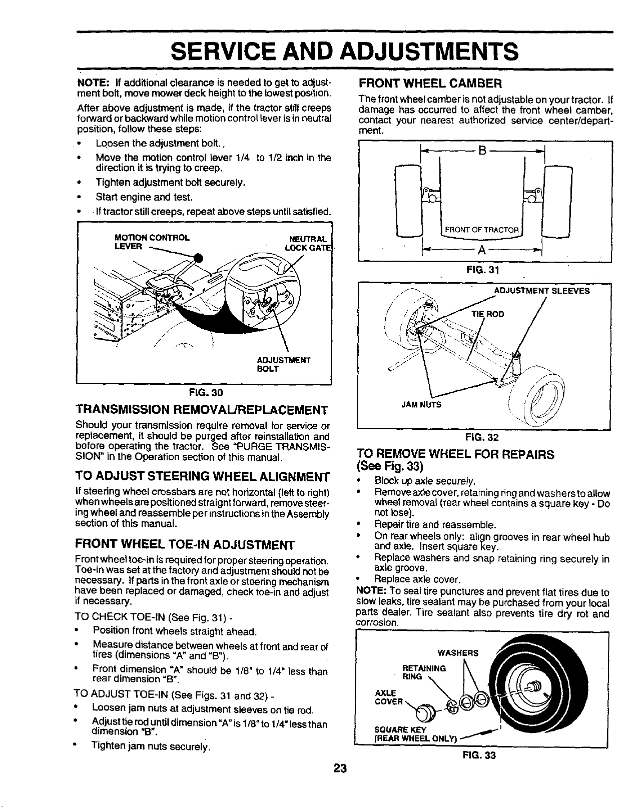
FRONT WHEEL CAMBER
NOTE: If additional clearance is needed to get to adjust-
ment bolt, move mower deck height to the lowest position.
After above adjustment is made, ifthe tractor stillcreeps
forward or backward while motion controllever isin neutral
position, follow these steps:
Loosen the adjustment bolt..
•Move the motion control lever 1/4 to 1/2 inch in the
direction it is trying to creep.
•Tighten adjustment bolt securely.
•Start engine and test.
•.Iftractor stillcreeps, repeat above steps untilsatisfied.
MOTION CONTROL NEUTRAL
LEVER LOCK GATE
ADJUSTMENT
BOLT
FIG. 30
TRANSMISSION REMOVAL/REPLACEMENT
Should your transmission require removal for service or
replacement, it should be purged after reinstallation and
before operating the tractor. See =PURGE TRANSMIS-
SION" in the Operation section of this manual.
TO ADJUST STEERING WHEEL ALIGNMENT
If steering wheel crossbars are not horizontal (left to right)
when wheels are positioned straight forward, remove steer-
ingwheel and reassemble per instructions in the Assembly
section of this manual.
FRONT WHEEL TOE-IN ADJUSTMENT
Front wheel toe-in isrequired for proper steering operation.
Toe*in was set at the factory and adjustment shouldnot be
necessary. If parts inthe front axle or steering mechanism
have been replaced or damaged, check toe-in and adjust
if necessary.
TO CHECK TOE-IN (See Fig. 31) -
• Position front wheels straight ahead.
•Measure distance between wheels at front and rear of
tires (dimensions "A" and =B").
•Front dimension =A" should be 1/8" to 1/4" less than
rear dimension =B".
TO ADJUST TOE-IN (See Figs. 31 and 32) -
•Loosen jam nuts at adjustment sleeves on tie rod,
• Adjust tie rod until dimension"A" is 1/8" to 1/4" less than
dimension =B".
"Tighten jam nuts securely.
23
The front wheel camber isnot adjustable on your tractor. If
damage has occurred to affect the front wheel camber,
contact your nearest authorized service center/depart-
ment.
B
]
A
FIG. 31
/
!
ADJUSTMENT SLEEVES
JAM NUTS \
FIG. 32
TO REMOVE WHEEL FOR REPAIRS
(See Fig. 33)
• Block up axle securely.
•Remove axle cover, retaining ringand washers toallow
wheel removal (rear wheel contains a square key - Do
not lose).
•Repair tire end reassemble.
• On rear wheels only: align grooves in rear wheel hub
and axle. Insert square key.
•Replace washers and snap retaining ring securely in
axle groove.
•Replace axle cover.
NOTE" To seal tire punctures and prevent flat tires due to
slow leaks, tire sealant may be purchased from your local
parts dealer. Tire sealant also prevents tire dry rot and
corrosion.
WASHERS
RETAINING
RING
AXLE
SQUARE KEY _ J
(REAR WHEELONLY)
FIG. 33
STORAGE
ENGINE
immediately prepare your tractor for storage at the end of
the season or ifthe tractor will not be used for 30 days or
more.
CAUTION: Never store the tractor with
gasoline in the tank inside a building
where fumes may reach an open flame
or spark. Allow the engine to cool
before storing in any enclosure.
TRACTOR
Remove mower from tractor for winter storage. When
mower is to be stored for aperiod of time, clean it thor-
oughly, remove all dirt, grease, leaves, etc. Store in a
clean, dry area.
• Cleanentiretractor(See=CLEANING"intheCustomer
Responsibilities section of this manual).
• Inspect and replace belts, if necessary (See belt re-
placement instructions in the Service and Adjustments
section of this manual).
•Lubricate as shown in the Customer Responsibilities
section of this manual.
•Be sure that all nuts, bolts and screws are securely
fastened. Inspect moving parts for damage, breakage
and wear. Replace if necessary.
•Touch up all rusted or chipped paint surfaces; sand
lightly before painting.
BATrERY
•Fully charge the battery for storage.
After a period of time in storage, battery may require
recharging.
To help prevent corrosion and power leakage during
tong periods of storage, battery cables should be
disconnected and battery cleaned thoroughly (see "TO
CLEAN BATTERY AND TERMINALS" in the Cus-
tomer Responsibilities section of this manual).
•After cleaning, leave cables disconnected and place
cables where they cannot come in contact with battery
terminals.
•If battery is removed from tractor for storage, do not
store battery directly on concrete or damp surfaces.
FUEL SYSTEM
IMPORTANT: IT IS IMPORTANT TO PREVENT GUM
DEPOSITS FROM FORMING IN ESSENTIAL FUEL
SYSTEM PARTS SUCH AS CARBURETOR, FUEL FILTER,
FUEL HOSE, OR TANK DURING STORAGE, ALSO,
EXPERIENCE INDICATES THAT ALCOHOL BLENDED
FUELS (CALLED GASOHOL OR USING ETHANOL OR
METHANOL) CAN ATTRACT MOISTURE WHICH LEADS
TO SEPARATION AND FORMATION OF ACIDS DURING
STORAGE• ACIDIC GAS CAN DAMAGE THE FUEL
SYSTEM OF AN ENGINE WHILE IN STORAGE•
•Drain the fuel tank.
•Start the engine and let it run until the tuel lines and
carburetor are empty.
•Never use engine or carburetor cleaner prod.ucts in the
fuel tank or permanent damage may occur.
•Use fresh fuel next season.
NOTE: Fuel stabilizer is an acceptable alternative in
minimizing the formation of fuel gum deposits during stor-
age. Add stabilizer to gasoline in fuel tank or storage
container. Always follow the mix ratio found on stabilizer
container. Run engine at least 10 minutes after adding
stabilizer to allow the stabilizer to reach the carburetor, Do
not drain the gas tank and carburetor if using fuel stabilizer.
ENGINE OIL
Drain oil (with engine warm) and replace with clean engine
oil. (See =ENGINE" in the Customer Responsibilities
section of this manual).
CYLINDER(S)
•Remove spark plug(s).
•Pour one ounce of oil through spark plug hole(s) into
cylinder(s).
•Turn ignition key to "START" position for a few seconds
to distribute oil.
•Replace with new spark plug(s).
OTHER
•Do not store gasoline from one season to another.
•Replace your gasoline can if your can starts to rust.
Rust and/or dirt in your gasoline will cause problems.
• if possible, store your tractor indoors and cover it to
give protection from dust and dirt.
• Cover your tractor with a suitable protective cover that
does not retain moisture. Do not use plastic. Plastic
cannot breathe which allows condensation to form and
will cause your tractor to rust.
IMPORTANT: NEVER COVER TRACT(_R WHILE ENGINE
AND EXHAUST AREAS ARE STILL WARM.
26
i
TROUBLESHOOTING POINTS
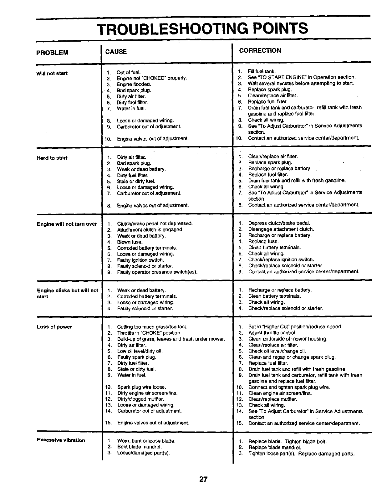
PROBLEM
Will not start
Hard to start
Engine will not turn over
Engine clicks but will not
start
Loss of power
Excessive vibration
CAUSE
t. Out ot fuai.
2. Engine not "CHOKED" properly.
3. Engine flooded.
• 4. Bad spark plug.
5. Dirty air filter.
6. Dirty fuel filter.
7. Water in fuel.
8. Loose or damaged widng.
9. Carburetor out of adjustment.
10. Engine valves out of adjustment•
1. O_rlyairfilter.
2. Badsparkplug.
3. Weakordead battery.
4. Didy fuai filter.
5. Stele ordirtyfuel.
6. Looseordamagedwidng.
7. Carburetoroutof adjustment.
8. Engine valves _of adjustment.
1. Clutohlbrake pedal not depressed.
2. Attachment clutch isengaged•
3. Weak or dead battery.
4. Blown fuse.
5. Corroded battery terminals.
6. Loose or damaged wiring.
7. Faulty ignition switch.
8. Faulty solenoid or starter.
9. Faulty operator presence switch(as).
1. Weak or dead battery.
2. Co_oded battery terminals.
3. Loose or damaged wiring.
4. Faulty solenoid or starter.
1. Cutting too much grass/tno fast.
2. Tnmffle in "CHOKE" position.
3. Build-up of grass, leaves and trash under mower.
4. Dirty air tilter.
5. Low oil level/dirty oil.
6. Faulty spark plug.
7. Dirty fuel filter.
B. State or dirty fuel.
9. Water in fuel.
10. Spark plug wire loose.
11. Dirty engine air screen/fins.
12. Dirty/ctogged muffler.
13. Loose or damaged widng.
t4. Carburetor out of adjustment.
15. Engine valves out of adjustment.
t. Worn, bent or loose blade.
2_ Bent blade mandrel.
3. Lnose/damaged part(s).
CORRECTION
1. F_IIfuai tank.
2. See "TO START ENGINE" in Operation section.
3. Wait several minutes before attempting to start.
4. Replace spark plug.
5. Ctean/replace air filter.
6. Replace fuel filter.
7. Drain fuel tank and carburetor, refill tank with fresh
gasaiine and replace fuel filter.
8. Check all wiring.
9. See "To Adjust Carburetor" in Service Adjustments
section.
10. Contact an autho_zed service center/depatl_nent.
1. CleaNreplace air filter•
2. Replace spark plug.
3• Recharge or replace battery..
4. Replace fuel liter.
5. Drain fuel tank and refill with fresh gasoline.
6. Check all wiling.
7. See "To Adjust Carburetor" in Service Adjustments
section.
8. Contact an authertzad service center/department.
1. Depress clutch/brake pedal.
2. Disengage attachment clutch.
3. Recharge or replace battery.
4. Replace fuse•
5. Ctean battery terminals.
6. Check all wiring.
7. Check/replace ig_itten switch.
8. Check/replace solenoid or starter.
9. Contact an authorized service center/depadment.
1. Recharge or replace battery.
2. Clean battery terminals.
3. Check all wiring.
4. Chack/raplace solenoid or starter.
1. Set in "Higher Cut_position/reduca speed.
2. Adjust throttle control
3. Clean underside of mower housing.
4. Clean/replace air filter.
5. Check oil level/change oil.
6. Clean and regap or change spark plug.
7. Replace fuel tilter.
B. Drain fuel tank and refill with fresh gasoline.
9. Drain fuel tank and carburetor, refill tank with fresh
gasoline and replace fuel filter.
10. Connect and tighten spark plug wire.
11. Clean engine air screen/fins.
12. Cteanireplece muffler.
13. Check ell wiring.
14. See =To Adjust Carburetor" in Service Adjustments
section.
t5. Contact an authorized service canter/department.
1. Replace blade. Tighten blade bolt.
2. Replace blade mandrel.
3. Tighten loose part(s). Replace damaged parts.
27
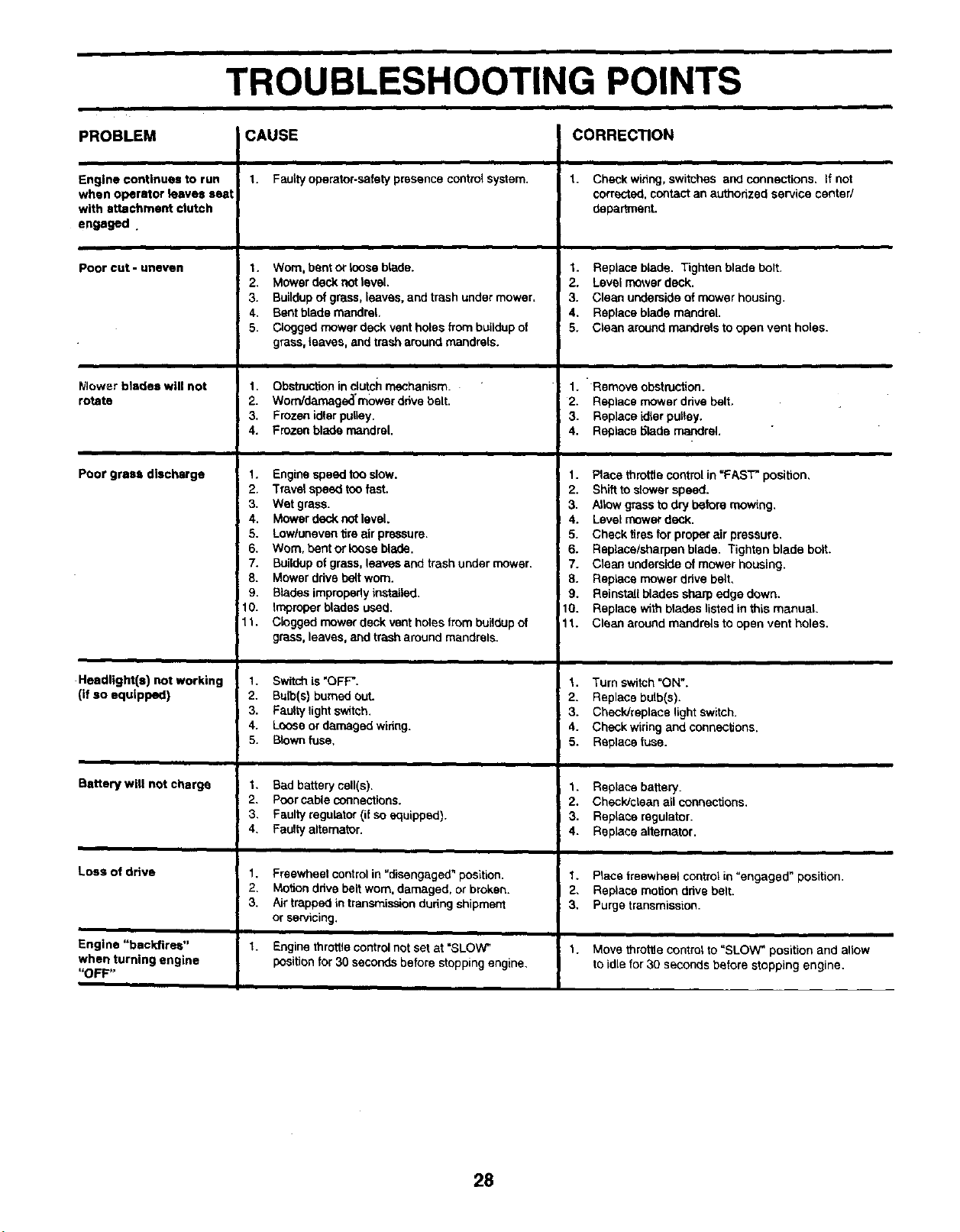
TROUBLESHOOTING POINTS
PROBLEM CAUSE CORRECTION
Engine continues to run
when operator leaves seat
with attachment clutch
engaged .
Poorcut-uneven
Mower blades will not
rotate
Poor gross discharge
Headlight(s) not working
(if so equipped)
Battery will not charge
Lose of drive
Engine "backfires"
when turning engine
"OFF"
1. Faulty operator-safety presence control system.
1. Worn,bentorloose blade.
2. Mowerdecknotlevel.
3. Buildupofgrass,leaves,andtrash undermower.
4. Bentblademandrel,
5. ClOggedmowerdeckventholesfrombuildupof
grass,leaves,andtrasharoundmandrels.
1. Ob_on in clutch mechanism.
2. WomJdarnage_'rnower dnve bolt.
3. Frozen idler pulley.
4. Frozen blade mandrel.
1. Engine speed too slow.
2. Travel speed too fasL
3. Wet grass.
4. Mower deck not level.
5. Low/uneven tire air pressure.
6. Worn. bent or loose blade.
7. Bu_dup of grass, leaves and trash under mower.
8. Mower ddve belt worn.
9. Blades improperly installed,
10. Improper blades used.
11. Clogged mower deck vent holes from buildup of
grass, leaves, and trash around mandrels.
1. Switch is "OFF".
2. Bulb(s) burned OUL
3. Faulty light switch.
4. Looes or damaged widng.
5. Blown fuse.
I. Bad battery cell(s).
2, Poor cable connections.
3, Faulty regulator (if so equipped).
4, Faulty alternator.
1. Freewheel control in "disengaged" position.
2. Motion ddve belt worn. damaged, or broken.
3. Air trapped in transmission dudng shipment
or servicing.
7. Enginethro_econtrolnot setat "SLOW"
positionfor 30 secondsbefore stopping engine.
1. Check winng, switches and connections, If not
corrected, contact an authorized service center/
department.
1. Replace blade. Tighten blade bolt.
2. Level mower deck.
3. Clean underside of mower housing.
4. Replace blade mandrel.
5. Clean around maedrats to open vent holes.
1. " Remove obstruction.
2. Replace mower dnve belt.
3. Replace idier pulley.
4. Replace 6lade mandrel.
1. Place throttle control in "FAST" position,
2. Shift to slower speed.
3. Allow grass to dry before mowing.
4. Level mower deck.
5. Check tires for proper air pressure.
6. Replace/sharpen blade. Tighten blade bolt.
7. Clean underside of mower housing.
8. Replace mower ddve belt,
9. Reinstall blades sharp edge down.
10. Replace with blades listed in this manual.
lt. Clean around mandrels to open vent holes.
7. Turn switch "ON".
2. Replace bulb(s).
3. Check/replace light switch.
4. Check wiring and conneclJons.
5. Replace fuse.
1. Replacebattery.
2. CheckJcteanall connections.
3. RopLasaregulator.
4. Replacealternator.
1. Place freewheel control in =engaged" position.
2, Replace motion drive belt.
3. Purge transmission.
1. Move throttle control to "SLOW _ position and allow
to idle for 30 seconds before stopping engine.
28
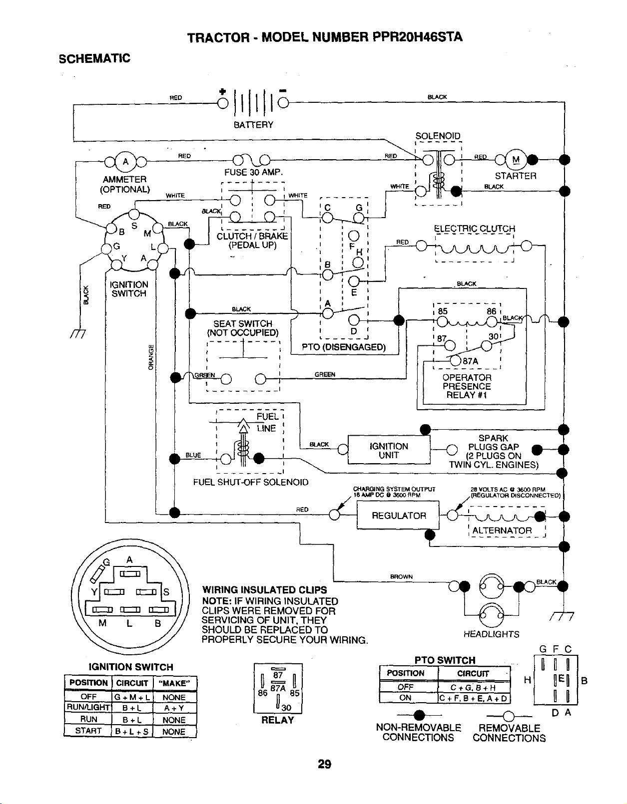
SCHEMATIC
TRACTOR - MODEL NUMBER PPR20H46STA
BATTERY
AMMETER
(OPTIONAL)
RED
SBLACK L ....... J
CLUTCH !BRAKE
(PEDAL UP)
IGNITION
SWITCH
BLACK
SEAT SWITCH
(NOT OCCUPIED)
t I
;I
I
©,
FUEL
BL/_.K
G
i
:O
:F
SOLENOID
i ......
I
I STARTER
WHrrE BLACK
RED
ELECTRIC CLUTCH
I--E
D
PTO (DISENGAGED)
GREEN
87A '
I
OPERATOR
PRESENCE
RELAY #1
IGNITION
UNIT
SPARK
PLUGS GAP
2PLUGS ON
TWIN CYL. ENG NES)
FUEL SHUT,OFF SOLENOID
RED
CHARGING SYSTEM OUTPUT 28 VOLTS AC @ 3600 RPM
I
',ALTERNATOR j
IGN! I'ION SWITCH
POSITION CIRCUIT "MAKE"
OFF G+M+L] NONE
RUN/LIGHT B + L A+ Y
RUN B + L NONE
B+L÷SI NONE
STABT
WIRING INSULATED CLIPS
NOTE: IF WIRING INSULATED
CLIPS WERE REMOVED FOR
SERVICING OF UNIT, THEY
SHOULD BE REPLACED TO
PROPERLY SECURE YOUR WIRING. HEADLIGHTS
/" 0
RELAY
PTO SWITCH " I _
POSmON ICIRCUIT .I H{
OFF _. C+G_B+H
ON IC_*D
• ©
NON-REMOVABLE REMOVABLE
CONNECTIONS CONNECTIONS
GFC
UEUB
UB
DA
29
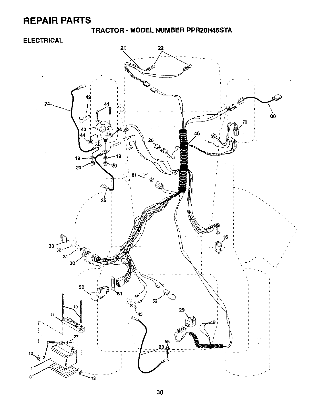
REPAIR PARTS TRACTOR -MODEL NUMBER PPR20H46STA
ELECTRICAL 21 22
2O
\
i
I i i
I i
Ii\80
i/
/
\
\
\
\\
/
/
,. /
.t
I
I
I
I
I
30
REPAIR PARTSTRACTOR -MODEL NUMBER PPR20H46STA
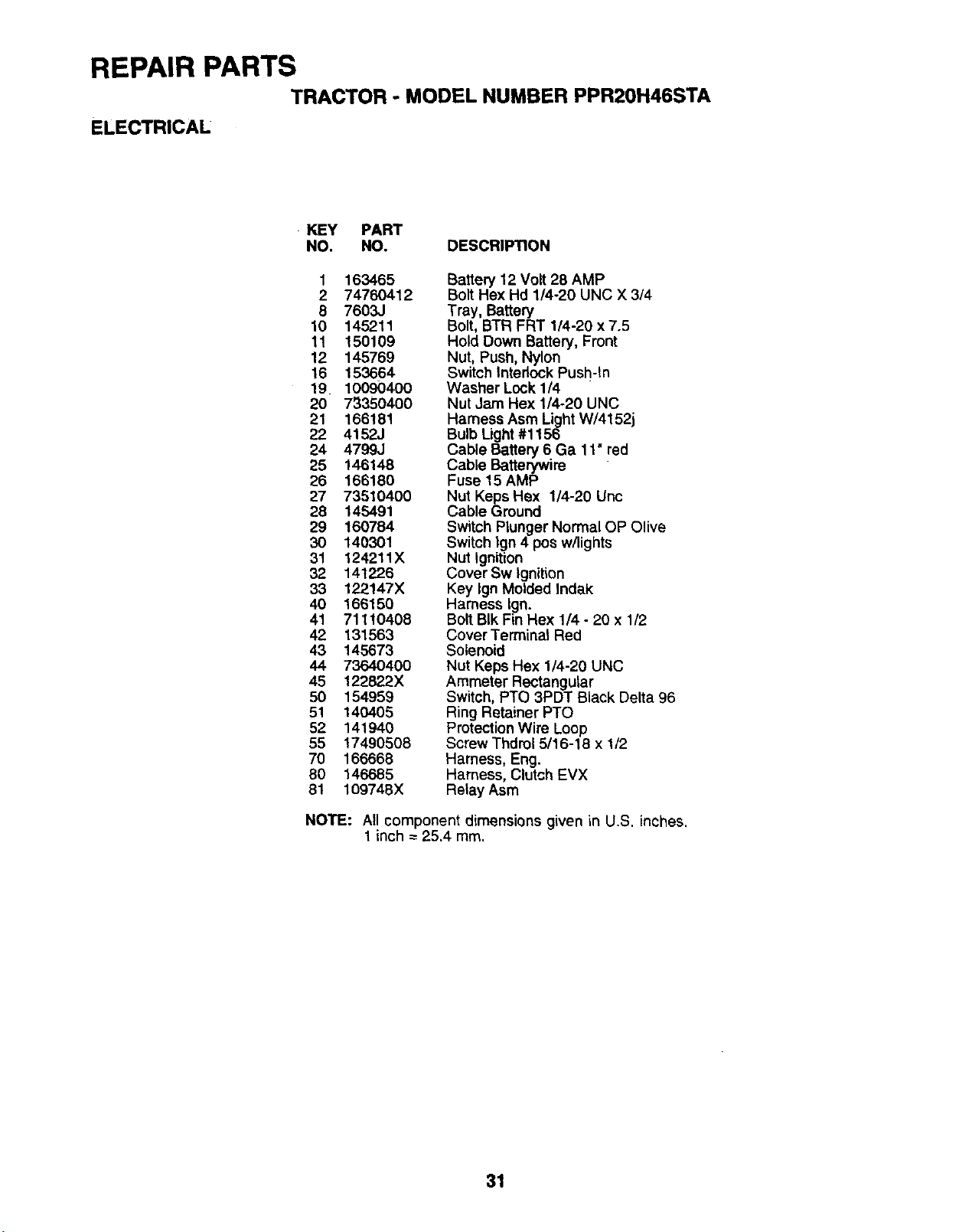
ELECTRICAL
KEY PART
NO. NO. DESCRIPTION
1 163465
2 74760412
8 7603J
10 145211
11 150109
12 145769
16 153664
19 10090400
20 7335O400
21 166181
22 4152J
24 4799J
25 146148
26 166180
27 73510400
28 145491
29 160784
30 140301
31 124211X
32 141226
33 122147X
40 166150
41 71110408
42 131563
43 145673
44 73640400
45 !22822X
50 154959
51 140405
52 141940
55 17490508
70 166668
80 146685
81 109748X
Battew 12 Volt 28 AMP
BoltHex Hd 1/4-20 UNC X 3/4
Tray, Battery
Bolt, BTR FRT 1/4-20 x 7.5
Hold Down Battery, Front
Nut, Push, Nylon
Switch Interlock Push-In
Washer Lock 1/4
Nut JeJnHex 1/4-20 UNC
Harness Asm Light W/4152j
Bulb Light#1156
Cable Battery 6 Ga 11" red
Cable Batterywire
Fuse 15 AMP
Nut Keps Hex 1/4-20 Unc
Cable Ground
Switch Plunger Normal OP Olive
Switch Ign 4 pos w/lights
Nut Ignition
Cover Sw Ignition
Key Ign Molded Indak
Hamess Ign.
Bolt BIk Fin Hex 1/4 - 20 x 1/2
Cover Terminal Red
Solenoid
Nut Keps Hex 1/4-20 UNC
Ammeter Rectangular
Switch, PTO 3PDT Black Delta 96
Ring Retainer PTO
Protection Wire Loop
Screw Thdrol 5/16-16 x1/2
Harness, Eng.
Harness, Clutch EVX
Relay Asm
NOTE: All component dimensions given in U.S. inches.
1 inch = 25,4 mm.
31
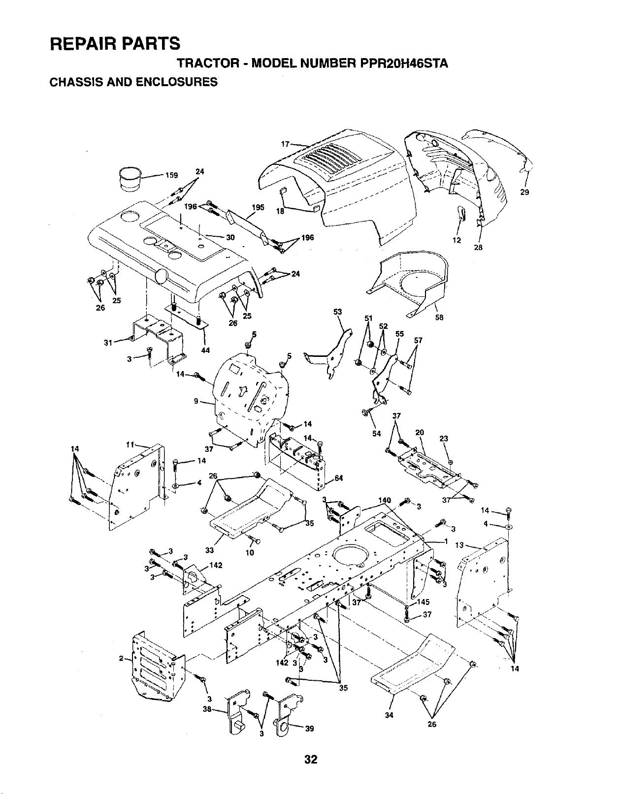
REPAIR PARTSTRACTOR -MODEL NUMBER PPR20H46STA
CHASSIS AND ENCLOSURES
14
26
24
33
25 58
26 52
lo
5
12 28
53
37
29
38
39
35
34 26
14
32
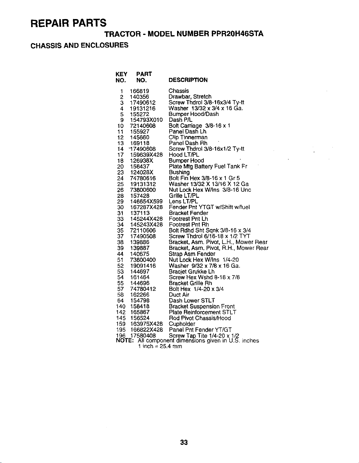
REPAIR PARTSTRACTOR -MODEL NUMBER PPR20H46STA
CHASSIS AND ENCLOSURES
KEY PART
NO. NO. DESCRIPTION
1 166819
2 140356
3 17490612
4 19131216
5 155272
9 154793X010
10 72140608
11 155927
12 145660
13 169118
14 "17490608
17 159639X428
18 126938X
20 156437
23 124028X
24 74780616
25 19131312
26 73800600
28 157428
29 146654X599
30 167287X428
31 137113
33 145244X428
34 145243X428
35 72110606
37 17490508
38 139886
39 139887
44 140675
51 73800400
52 19091416
53 144697
54 161464
55 144696
57 74780412
58 162266
64 154798
140 158418
142 165867
145 156524
159 163975X428
Chassis
Drawbar, Stretch
Screw Thdrol 3/8-16x3/4 Ty-tt
Washer 13/32 x 3/4 x 16 Ga.
Bumper Hood/Dash
Dash P/L
Bolt Carriage 3/8-16 x 1
Panel Dash Lh
Clip Tinnerman
Panel Dash Rh
Screw Thdrot 3/8-16xl/2 Ty-tt
Hood LT/PL
Bumper Hood
Plate Mtg Battery Fuel Tank Fr
Bushing
Bolt Fin Hex 3/8-16 x 1 Gr 5
Washer 13/32 X 13/16 X 12 Ga
Nut Lock Hex W/Ins 3/8-16 Uric
Gdlle LT/PL
Lens LT/PL
Fender Pnt YTGT w/Shift w/fuel
Bracket Fender
Footrest Pnt Lh
Footrest Pnt Rh
Bolt Rdhd Sht Sqnk 3/8-16 x 3/4
Screw Thdrol 6/16-18 x 1/2 TYT
Bracket, Asm. Pivot, L.H., MQwer Rear
Bracket, Asm. Pivot, R.H., Mower Rear
Strap Asm Fender
Nut Lock Hex W/Ins 1/4-20
Washer 9/32 x 7/8 x 16 Ga.
Bracjet Grukke Lh
Screw Hex Wshd 8-18 x 7/8
Bracket Grille Rh
Bolt Hex 1/4-20 x 3/4
Duct Air
Dash Lower STLT
Bracket Suspension Front
Plate Reinforcement STLT
Rod Pivot Chassis/Hood
Cupholder
195 166822X428 Pane_ Pnt FenderYT/GT
196 17580408 Screw Tap Tite 1/4-20 x 1/2
NOTE: All component dimensions given in U.S. inches
1 inch = 25.4 rnm
33
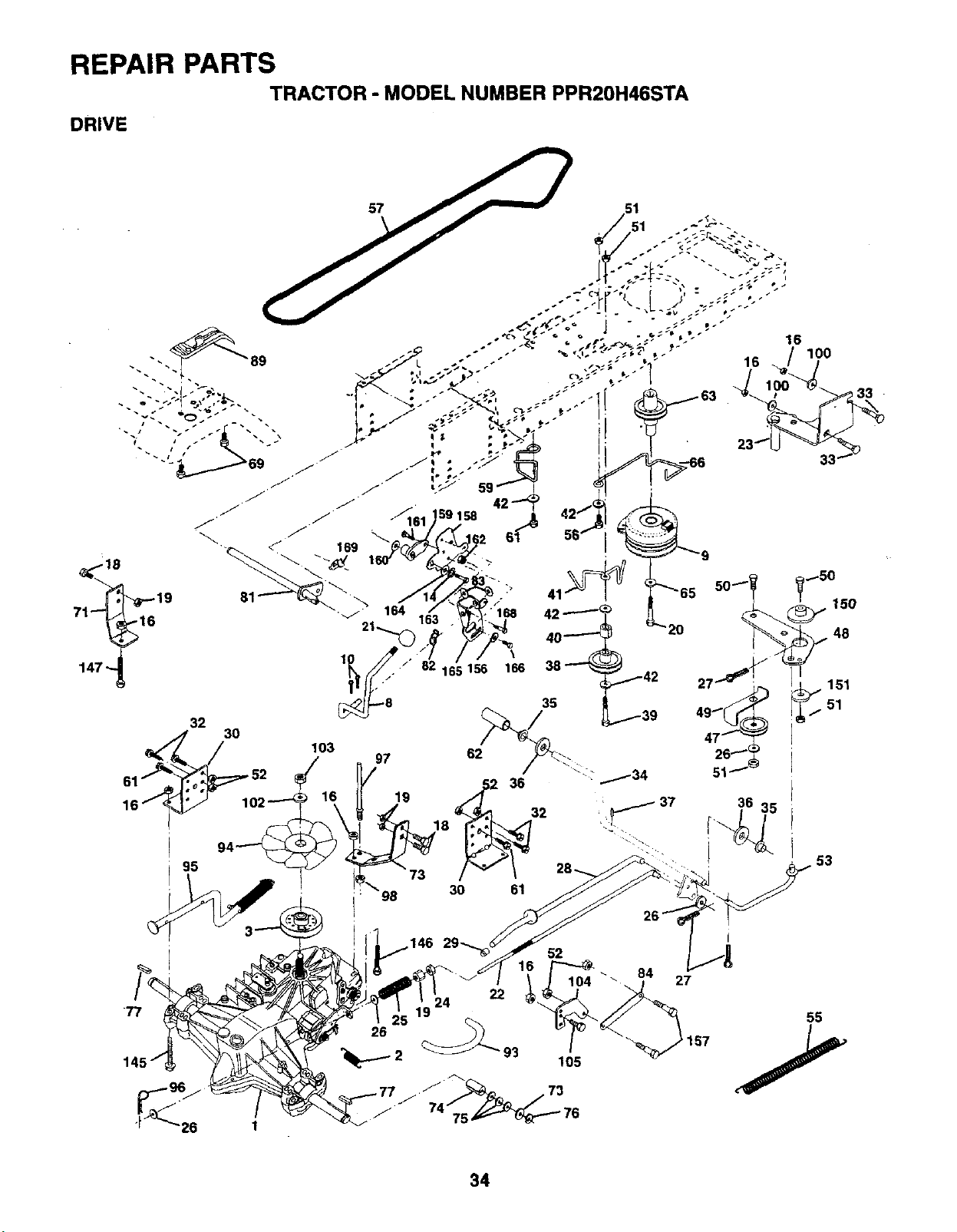
REPAIR PARTSTRACTOR "MODEL NUMBER PPR20H46STA
DRIVE
89
71_1619
147"_
16 100
33
32 103 62
97
/,52 36
30 61
53
52
27
55
34
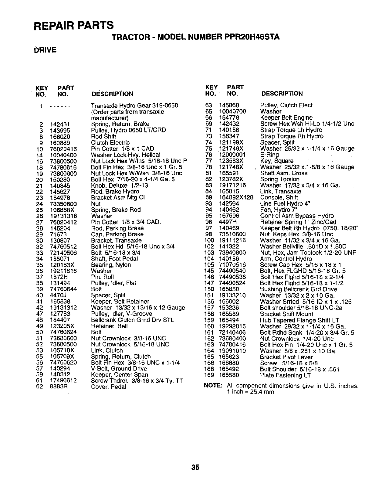
REPAIR PARTSTRACTOR -MODEL NUMBER PPR20H46STA
DRIVE
KEY PART KEY PART
NO. "NO. DESCRIP_ON NO." NO.
1 ......
2142431
3 143995
8 166020
9 160889
10 76020416
14 10040400
16 73800500
18 74780616
19 73800600
20 150280
21 140845
22 145627
23 154978
24 73350600
25 106888X
26 19131316
27 76020412
28 145204
29 71673
30 130807
32 74760512
33 72140506
34 155071
35 120183X
36 19211616
37 1572H
38 131494
39 74760644
40 4470J
41 165838
42 19131312
47 127783
48 154407
49 123205X
50 74760624
51 73680600
52 73680500
53 105710X
55 105709X
56 74760620
57 140294
59 140312
61 17490612
62 8863R
Transaxte Hydro Gear319-0650 63 145868
(Order parts lrom transaxle 65 10040700
manufacturer) 66 154778
Spring, Return, Brake 69 142432
Pulley, Hydro 0650 LT/CRD 71 140158
Rod Shift 73 156347
Clutch Electric 74 121199X
Pin Cotter 1/8 x 1 CAD 75 121749X
Washer Lock Hvy. Helical 76 12000001
Nut Lock Hex W/Ins 5/16-18 Unc P 77 123583X
Bolt Fin Hex 3/8-16 Unc x 1 Gr. 5 78 121748X
Nut Lock HexW/Wsh 3/8-16 Unc 81 165591
Bolt Hex 7/16-20 x 4-1/4 Ga. 5 82 123782X
Knob, Deluxe 1/2-13 83 19171216
Rod, Brake Hydro 84 1658!5
Bracket Asm Mtg CI 89 164892X428
Nut 93 142564
Spring, Brake Rod 94 140462
Washer 95 167696
Pin Cotter 1/8 x3/4 CAD. 96 4497H
Rod, Parking Brake 97 140469
Cap, Parking Brake 98 73510600
Bracket, Transaxle 100 19111216
Bolt Hex Hd 5/16-18 Unc x 3/4 102 141322
Bolt 5/16-18 x 3/4 103 73940800
Shaft, Foot Pedal 104 140156
Bearing, Nylon 105 71070516
Washer 145 74490540
Pin, Roll 146 74490536
Pulley, Idler, Flat 147 74490524
Bolt 150 165850
Spacer, Split 151 19133210
Keeper, Belt Retainer 156 166002
Washer 13/32 x13/16 x12 Gauge !57 153236
Pulley, Idler, V-Groove 158 165589
Bellcrank Crutch Grnd Dry STL 159 165494
Retainer, Belt 160 19292016
Bolt 161 72140406
Nut Crowniock 3/8-16 UNC 162 73680400
Nut Crownlock 5/16-18 UNC 163 74780416
Link, Clutch 164 19091010
Spring, Return, Clutch !65 165623
Bolt Fin Hex 3/8-16 UNC x 1-1/4 166 166880
V-Belt, Ground Drive 168 165492
Keeper, Center Span 169 165580
Screw Thdrol. 3/8-16 x 3/4 Ty. TT
Cover, Pedal
DESCRIPTION
Pulley, Clutch Elect
Washer
Keeper Belt Engine
Screw Hex Wsh Hi-Lo 1/4-1/2 Unc
Strap Torque Lh Hydro
Strap Torque Rh Hydro
Spacer, Split
Washer 25/32 x 1-1/4 x 16 Gauge
E-Ring
Key, Square
•Washer 25/32 x.1-5/8 x 16 Gauge
Shaft Asm. Cross
Spdng Torsion
Washer 17/32 x 3/4 x 16 Ga.
Link, Transaxle
Console, Shift
Line Fuel Hydro 4"
Fan, Hydro 7"
Contro/Asm Bypass Hydro
Retainer Spring 1" Zinc/Cad
Keeper Belt Rh Hydro 0750. 18/20"
Nut Keps Hex 3/8-16 Unc
Washer 11/32 x 3/4 x 16 Ga.
Washer Beliville .501D x 1.50D
Nut, Hex, Jam Toplock 1/2-20 UNF
Arm, Control Hydro
Screw Cap Hex 5/16x 18x 1
Bolt, Hex FLGHD 5/16-18 Gr. 5
Bolt Hex Flghd 5/16-18 x 2-1/4
Bolt Hex Flghd 5/16-18 x 1-1/2
Bushing Bellcrank Grd Drive
Washer 13/32 x 2 x 10 Ga.
Washer Srrted 5/16 ID x 1 x .125
Bolt shoulder 5/16-18 UNC-2a
Bracket Shift Mount
Hub Tapered Flange Shift LT
Washer 29/32 x 1-!/4 x 16 Ga.
Bolt Rdhd Sqnk 1/4-20 x 3/4 Gr. 5
Nut Crownlock 1/4-20 Unc
Bolt Hex Fin 1/4-20 Uric x 1 Gr. 5
Washer 5/8 x .281 x 10 Ga.
Bracket Pivot Lever
Screw 5/16-18 x 5/8
Bolt Shoulder 5/16-18 x .561
Plate Fastening LT
NOTE: All component dimensions give in U.S. inches.
1 inch = 25.4 mm
35
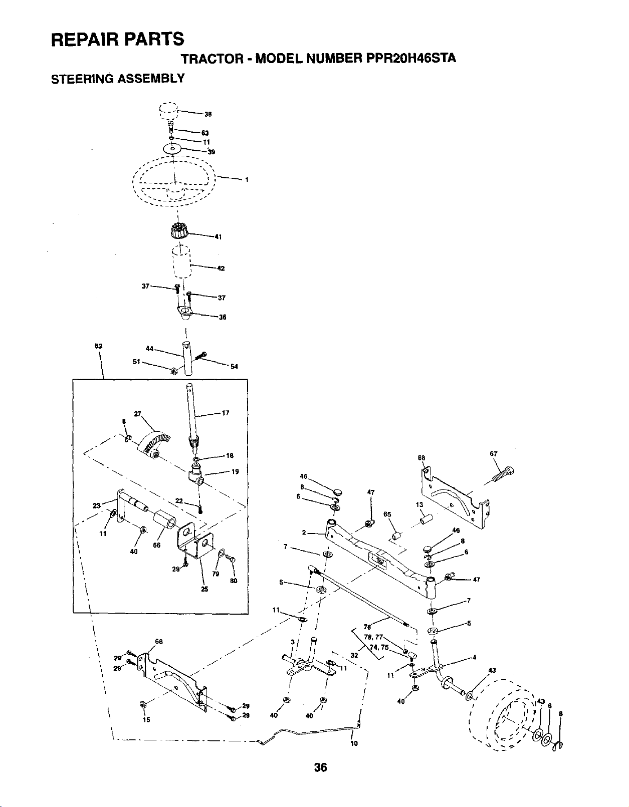
REPAIR PARTSTRACTOR -MODEL NUMBER PPR20H46STA
STEERING ASSEMBLY
67
68
6 47
/
68
i+__
36
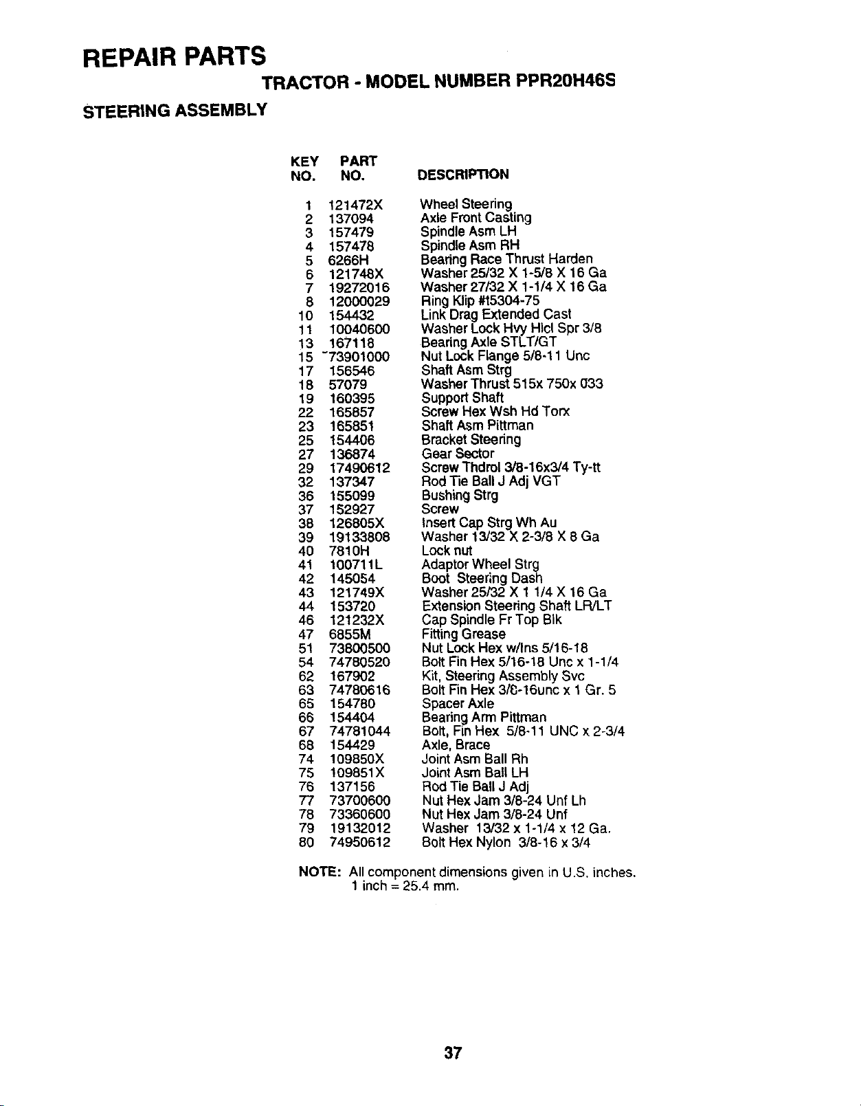
REPAIR PARTSTRACTOR -MODEL NUMBER PPR20H46S
STEERING ASSEMBLY
KEY PART
NO. NO, DESCRIPTION
1121472X
2137094
3 157479
4 157478
56266H
6121748X
719272016
8 12000029
10 154432
11 10040600
13 167118
15 -73901000
17 156548
18 57079
19 160395
22 165857
23 165851
25 154406
27 136874
29 17490612
32 137347
36 155099
37 152927
38 126805X
39 19133808
40 7810H
41 100711L
42 145054
43 121749X
44 153720
46 121232X
47 6855M
51 73800500
54 74780520
62 167902
63 74780616
65 154780
66 154404
67 74781044
68 154429
74 109850X
75 !09851X
76 137156
77 73700600
78 73360600
79 19132012
80 74950612
Wheel Steering
Axle Front Casting
Spindle Asm LH
Spindle Asm RH
Beadng Race Thrust Harden
Washer 25/32 X 1-5/8 X 16 Ga
Washer 27/32 X 1-1/4 X 16 Ga
Ring Klip #t5304-75
Link Drag Extended Cast
Washer Lock Hvy Hlcl Spr 3/8
Bearing Axle STLT/GT
Nut Lock Flange 5/8-11 Unc
Shaft Asm Strg
Washer Thrust 515x 750x 033
Support Shaft
Screw Hex Wsh Hd Torx
Shaft Asm Pittman
Bracket Steedng
Gear Sector
Screw Thdrol 3/8-16x3/4 Ty-tt
Rod Tie Ball J Adj VGT
Bushing Strg
Screw
Insert Cap Strg Wh Au
Washer 13/32 X 2-3/8 X 8 Ga
Lock nut
Adaptor Wheel Strg
Boot Steering Dash
Washer 25/32 X 1 1/4 X 16 Ga
Extension Steering Shaft LR/LT
Cap Spindle Fr Top BIk
FittingGrease
Nut Lock Hex w/Ins 5/16-18
BoltFin Hex 5/16-18 Unc x 1-1/4
Kit, Steering Assembly Svc
Bolt Fin Hex 3/_-16unc x 1 Gr. 5
Spacer Axle
Beadng Arm Pittman
Bolt, Fin Hex 5/8-11 UNC x 2-3/4
Axle, Brace
Joint Asm Ball Rh
Joint Asm Ball LH
Rod Tie Ball J Adj
Nut Hex Jam 3/8-24 Unf Lh
Nut Hex Jam 3/8-24 Unf
Washer 13/32 x 1-1/4 x 12 Ga.
Bolt Hex Nylon 3/8-16 x 3/4
NOTE: All component dimensions given in U.S. inches.
1 inch = 25.4 ram.
37
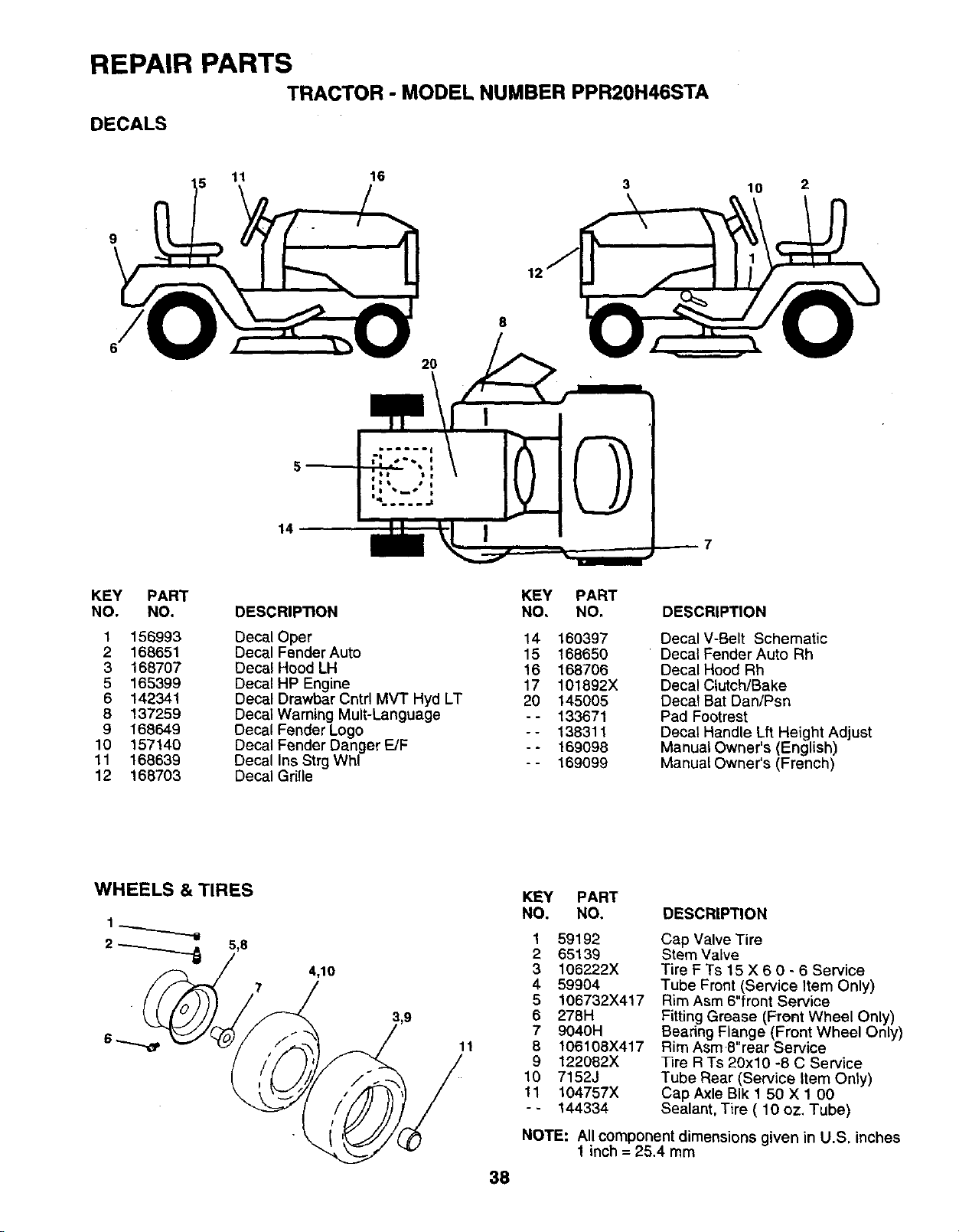
REPAIR PARTSTRACTOR -MODEL NUMBER PPR20H46STA
DECALS
11 16 10 2
9
2O
14
KEY PART KEY PART
NO. NO. DESCRIP_ON NO, NO.
1 156993
2 168651
3 168707
5 165399
6 142341
8 137259
9 168649
10 157140
11 168639
12 168703
Decal Oper 14 160397
Decal Fender Auto 15 168650
Decal Hood LH 16 168706
Decal HP Engine 17 101892X
Decal Drawbar Cntrl MV"I" Hyd LT 20 145005
DecalWarning Mult-Language -- 133671
Decal Fender Logo - - 138311
Decal Fender Danger E/F - - 169098
Decal Ins Strg Wh! - - 169099
Decal Grille
DESCRIPTION
Decal V-Belt Schematic
Decal Fender Auto Rh
Decal Hood Rh
Decal Clutch/Bake
Decat Bat Dan/Psn
Pad Footrest
Decal Handle Lft Height Adjust
Manual Owner's (English)
Manual Owner's (French)
WHEELS & TIRES
4,10
7
11
38
KEY PART
NO. NO. DESCRIPTION
1 59192
2 65139
3 106222X
4 59904
5 106732X417
6 278H
7 9040H
8 106108X417
9 122082X
10 7152J
11 104757X
-- 144334
Cap Valve Tire
Stem Valve
Tire F Ts 15 X 6 0 - 6 Service
Tube Front (Service Item Only)
Rim Asm 6"front Service
Fitting Grease (Front Wheel Only)
Bearing Flange (Front Wheel Only)
Rim AsmS"rear Service
Tire R Ts 20x10 -8 C Service
Tube Rear (Service Item Only)
Cap Axle BIk 1 50 X 1 00
Sealant, Tire ( 10 oz. Tube)
NOTE: All component dimensions given in U.S. inches
1 inch = 25.4 mm
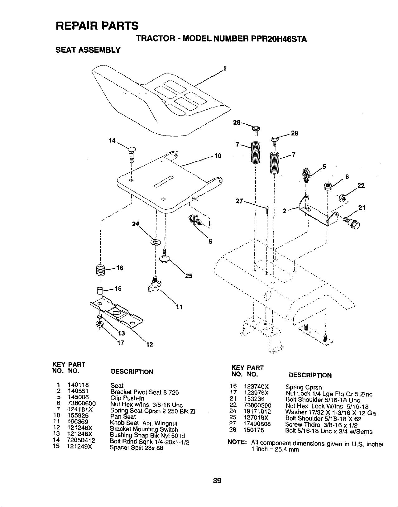
REPAIR PARTSTRACTOR -MODEL NUMBER PPR20H46STA
SEAT ASSEMBLY
I
17 12
11
5
KEY PART
NO. NO.
1 140118
2 140551
5t45006
6 73800600
7 124181X
10 155925
11 166369
12 121246X
13 121248X
14 72050412
15 121249X
DESCRIPTION
Seat
Bracket Pivot Seat 8 720
Clip Push-In
Nut Hex w/|ns. 3/6-16 Unc
Spring Seat Cprsn 2 250 BIk Zi
Pan Seat
Knob Seat Adj, Wingnut
Bracket Mounting Switch
Bushing Snap BIk Nyl 50 Id
Bolt Rdhd Sqnk 1/4-20x1-1/2
Spacer Split 26x 88
KEY PART
NO. NO, DESCRIPTION
16 123740X
17 123976X
21 153236
22 738005O0
24 19171912
25 127016X
27 17490608
28 150176
Spring Cprsn
Nut Lock !14 Lge Fig Gr 5 Zinc
Bolt Shoulder 5/16-18 Unc
Nut Hex Lock W/Ins 5/16-18
Washer 17/32 X 1-3/16 X 12 Ga.
Bolt Shoulder 5;'16-18 X 62
Screw Thdrol 3/B-16 x 1/2
Bolt 5/16-18 Unc x 3/4 w/Sems
NOTE: All component dimensions given in U,S. inche=
1 inch = 25.4 mm
39
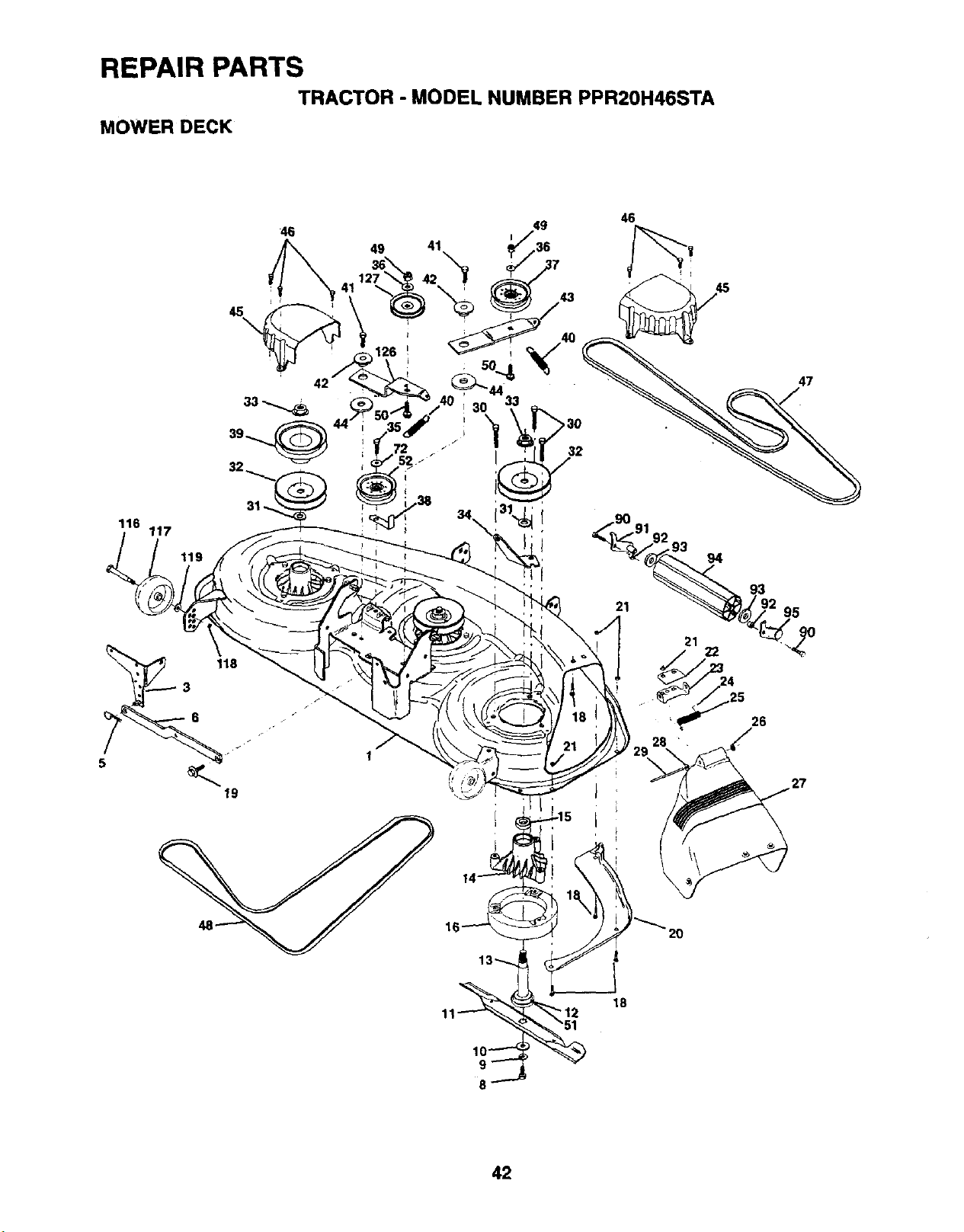
REPAIR PARTSTRACTOR -MODEL NUMBER PPR20H46STA
MOWER DECK
116 117
119
46
94
47
18
8
42
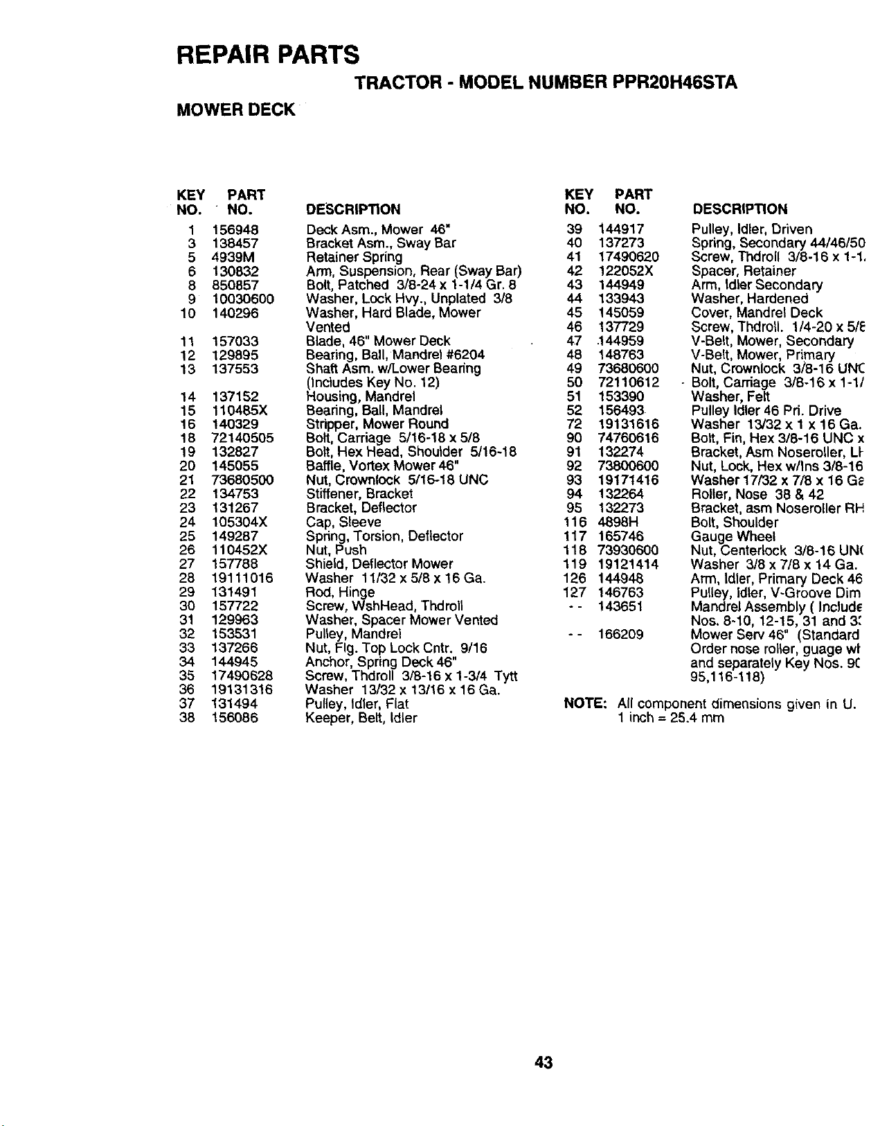
REPAIR PARTSTRACTOR -MODEL NUMBER PPR20H46STA
MOWER DECK
KEY PART
NO. " NO.
1 156948
3 138457
5 4939M
6 130832
8 850857
910030600
10 140296
11 157033
12 129895
13 137553
14 137152
15 110485X
16 140329
18 7214O505
19 132827
20 145055
21 73680500
22 134753
23 131267
24 105304X
25 149287
26 110452X
27 157788
28 19111016
29 131491
30 157722
31 129963
32 153531
33 137266
34 144945
35 17490628
36 19131316
37 131494
38 156086
DESCRIPTION KEY PART
NO. NO.
DeckAsm., Mower 46" 39 144917
Bracket Asm., Sway Bar 40 137273
Retainer Spring 41 17490620
Arm, Suspension, Rear (Sway Bar) 42 122052X
Bolt, Patched 3/8-24 x 1-1/4 Gr. 8 43 144949
Washer, Lock Hvy., Unplated 3/8 44 133943
Washer, Hard Blade, Mower 45 145059
Vented 46 137729
Blade, 46" Mower Deck 47 .144959
Bearing, Bali, Mandrel #6204 48 148763
Shaft Asm. w/Lower Beadng 49 73680600
(Includes Key No. 12) 50 72110612
Housing, Mandrel 51 153390
Beadng, Ball, Mandrel 52 156493
Stripper, Mower Round 72 19131616
Bolt, Carriage 5/16-18 x 5/8 90 74760616
Bolt, Hex Head, Shoulder 5/16-18 91 132274
Baffle, Vortex Mower 46" 92 73800600
Nut, Crownlock 5/16-18 UNC 93 19171416
Stiffener, Bracket 94 132264
Bracket, Deflector 95 132273
Cap, Sleeve 116 4898H
Spring, Torsion, Deflector 117 165746
Nut, Push 118 73930600
Shield, Deflector Mower 119 19121414
Washer 11/32 x5/8 x 16 Ga. 126 144948
Rod, Hinge 127 146763
Screw, WshHead, Thdmll -- 143651
Washer, Spacer Mower Vented
Pulley, Mandrel -- 166209
Nut, Fig. Top Lock Cntr. 9/16
Anchor, Spring Deck 46"
Screw, Thdroll 3/8-16 x 1-3/4 Tytt
Washer 13/32 x 13/16 x 16 Ga.
Pulley, Idler, Flat
Keeper, Belt, Idler
DESCRIPTION
Pulley, Idler, Driven
Spring, Secondary 44/46/50
Screw, Thdroll 3/8-16 x 1-1,
Spacer, Retainer
Arm, Idler Secondary
Washer, Hardened
Cover, Mandrel Deck
Screw, Thdroll. 1/4-20 x 5/e
V-Belt, Mower, Secondary
V-Belt, Mower Primary
Nut, Crownock 3/8-16 UNC
•Bolt, Carriage 3/8-16x 1-1/
Washer, Felt
Pulley Idler 46 Pri. Drive
Washer 13/32 x 1 x 16 Ga.
Bolt, Fin, Hex 3/8-16 UNC x
Bracket, Asm Noseroller, LI-
Nut, Lock, Hex w/Ins 3/3-16
Washer 17/32 x 7/8 x 16 G_-
Roller, Nose 38 & 42
Bracket, asm Noseroller RH
Bolt, Shoulder
Gauge Wheel
Nut, Centeriock 3/8-16 UN(
Washer 3/8 x 7/8 x 14 Ga.
Arm, Idler, Primary Deck 46
Pulley, Id|er, V-Groove Dim
Mandrel Assembly ( Includ_
Nos. 8-10, 12-15, 31 and 3."
Mower Serv 46" (Standard
Order nose roller, guage wt
and separately Key Nos. 9(:
95,116-1!8)
NOTE: All component dimensions given in U.
1 inch =25.4 mm
43
PARTS AND SERVICE
Your POULAN PRO product has been expertly engineered and carefully manufactured to rigic
quality standards. As with all mechanical products, some adjustments or part replacement ma_
be necessary during the life of your unit.
FOR SERVICE OR REPLACEMENT PARTS:
1. Consult your dealer/place of purchase.
2. Consult the yellow pages of your phone directory for the name of the nearest service deale)
(under "saws" for Chain Saws or under "lawn mowers" for Trimmers, Brushcutters, aJlc
Blowers).
3. For replacement parts, have available the following information:
a. Model Number/Manufacturer's I.D. Number
b. Description of part.
NOTE: Frigidaire Home Products provides parts and service through its authorized distribt
tors and dealers; therefore, all requests for parts and service should be directed to you
local dealer(s). The philosophy of Frigidaire Home Products is to continually impro,
all of its products. If the operating characteristics or the appearance of your produq
differs from those described in this Manual, please contact your local dealer
updated information and assistance.