®
r
SYSTEM 3L
Model No. 031.159421
Serial No.
Write the serial number in the
space above for reference.
Serial Number Decal (Under Seat)
CAUTION!
Read all safety precautions and
instructions in this owner's
manual before using this
equipment. Save this owner's
manual for future reference.
PATENT PENDING
TM
OWNER'S MANUAL
SEARS, ROEBUCK AND CO., HOFFMAN ESTATES, IL 60179
TABLE OF CONTENTS
IMPORTANT SAFETY PRECAUTIONS ....................................................... 2
BEFORE YOU BEGIN ................................................................... 3
ASSEMBLY ........................................................................... 4
USING THE SYSTEM 300 ............................................................... 18
TROUBLE-SHOOTING AND MAINTENANCE ................................................. 21
CABLE DIAGRAMS .................................................................... 22
ORDERING REPLACEMENT PARTS ............................................... Back Cover
LIMITED WARRANTY ........................................................... Back Cover
IMPORTANT SAFETY PRECAUTIONS
WARNING: To reduce the risk of serious injury, read the following important safety precautions before
using the SYSTEM 300.
1. Read all instructions in this owner's manual and in the accompanying literature before using the
SYSTEM 300.
2. Use the SYSTEM 300 only on a level surface, Cover the floor underneath the SYSTEM 300 to protect it.
3. Inspect and tighten all parts each time you use the SYSTEM 300. Replace any worn or frayed parts
immediately.
4. Keep small children away from the SYSTEM 300 at all times.
5. The SYSTEM 300 is designed to be used by only one person at a time.
6. Keep hands and feet away from movino Darts.
7. Always wear athletic shoes for foot protection.
8. Make sure that the cables remain on the pulleys at all times. If the cables bind as you are exercising,
stop immediately and make sure that the cables are on all of the pulleys.
9. Remove the lat bar from the high pulley station when performing any exercise that does not use the
lat bar.
10. If you feel pain or dizziness at any time while exercising, stop immediately and begin cooling down.
WARNING: Before beginning this or any exercise program, consult your physician. This Is especially
important for persons over the age of 35 or persons with pre-existing health problems. Read all instruc-
tions before using. SEARS assumes no responsibility for personal injury or property damage sustained
by or through the use of this product.
2
BEFORE YOU BEGIN
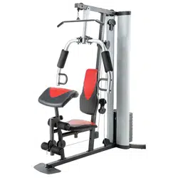
Thank you for selecting the LIFESTYLER ®SYSTEM 300 Weight System. The versatile SYSTEM 300 features
an impressive array of weight stations designed to develop every major muscle group of the body. Whether your
goal is a shapely figure, dramatic muscle size and strength, or a healthier cardiovascular system, the SYSTEM
300 will help you to achieve the specific results you want.
For your safety and benefit, read this manual carefully before using the SYSTEM 300. If you have addition-
al questions, please call our Customer Service Department toll-free at 1-800-999-3756, Monday through Friday,
6a.m. until 6p.m. Mountain Time (excluding holidays). To help us assist you, please note the product model
number and serial number before calling. The model number is 831 .t 59421. The serial number can be found on
a decal attached to the SYSTEM 300 (see the front cover of this owner's manual).
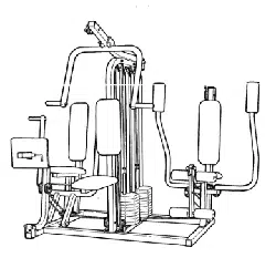
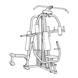
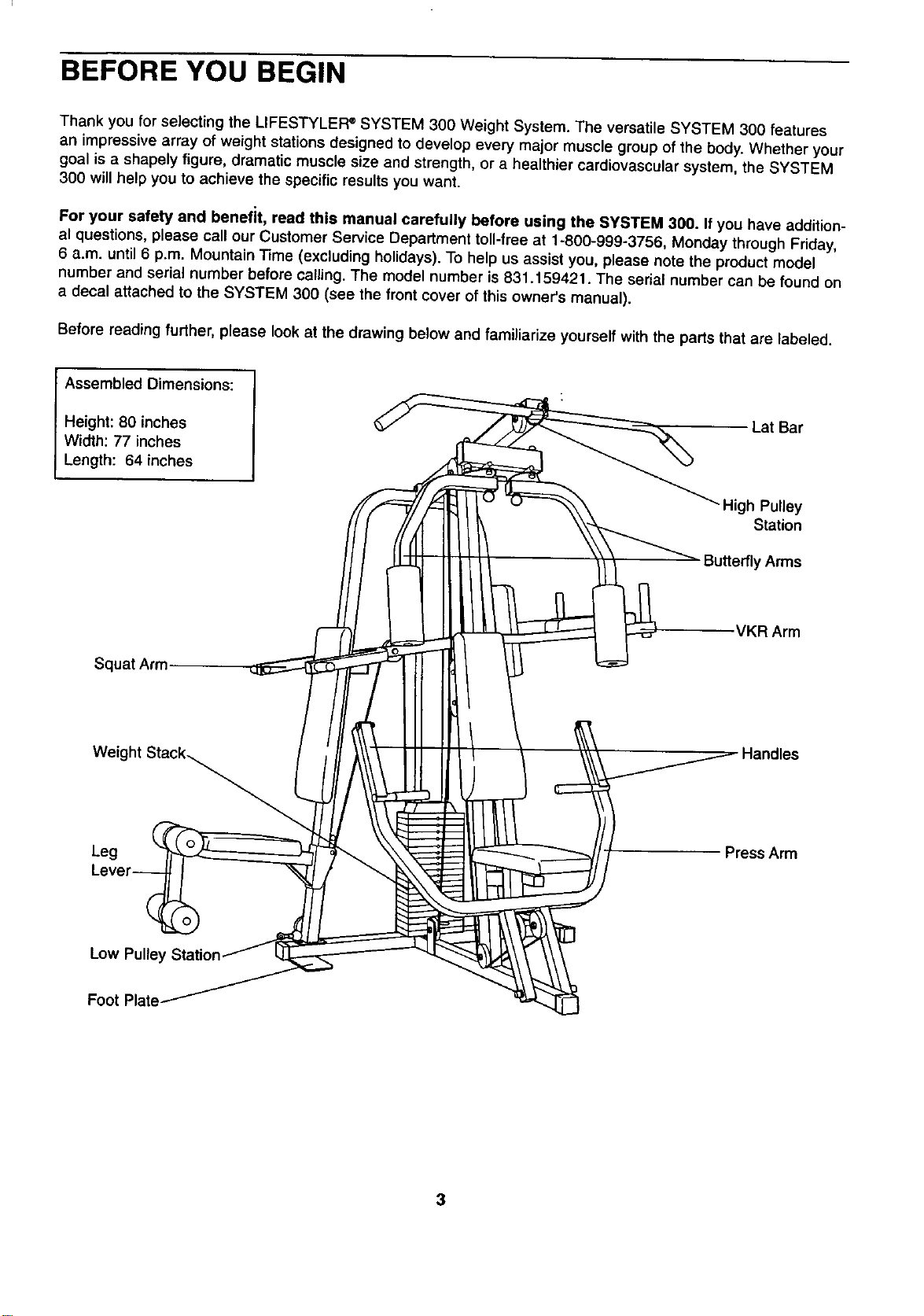
Before reading further, please look at the drawing below and familiarize yourself with the parts that are labeled.
Assembled Dimensions:
Height: 80 inches
Width: 77 inches
Length: 64 inches
Lat Bar
_High Pulley
Station
Butterfly Arms
VKR Arm
Squat Arm
Weight Stack_
Leg
Handles
Press Arm
Low Pulley Station.
Foot Plate
3
ASSEMBLY
Assembly requires two people. Due to the size and weight of the SYSTEM 300, itshould be assembled in the
location where it will be used.
Place all parts of the SYSTEM 300 in acleared area and remove the packing materials. Do not dispose of the
packing materials until assembly is completed. Before beginning assembly, read each step and look at each
drawing carefully. As you assemble the SYSTEM 300, make sure that all parts are oriented exactly as shown in
the drawings. Tighten all nuts and bolts as you attach them, unless instructed to do otherwise. For help identify-
ing the small parts used in assembly, refer to the PART CHART accompanying this owner's manual.
THE FOLLOWING TOOLS (NOT INCLUDED) ARE REQUIRED FOR ASSEMBLY: Two adjustable wrenches, a
phillips screwdriver and a rubber mallet. Grease and a small bowl of soapy water are also needed.
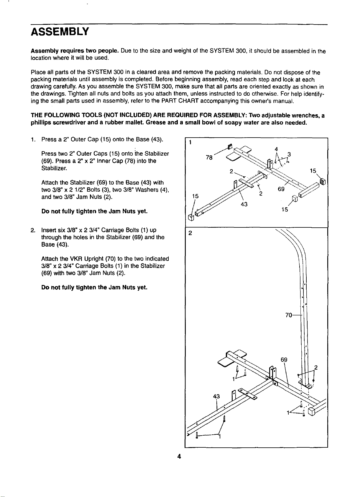
1. Press a 2" Outer Cap (15) onto the Base (43).
2.
Press two 2" Outer Caps (15) onto the Stabilizer
(69). Press a 2" x 2" Inner Cap (76) into the
Stabilizer.
Attach the Stabilizer (69) to the Base (43) with
two 3/8" x 2 1/2" Bolts (3), two 3/8" Washers (4),
and two 3/8" Jam Nuts (2).
Do not fully tighten the Jam Nuts yet.
Insert six 3/8" x 2 3/4" Carriage Bolts (1) up
through the holes in the Stabilizer (69) and the
Base (43).
Attach the VKR Upright (70) to the two indicated
3/8" x 2 3/4" Carriage Bolts (1) in the Stabilizer
(69) with two 3/8" Jam Nuts (2).
Do not fully tighten the Jam Nuts yet.
15
78
43
43
4
2
3
69
15
69
15
2
4
3. 3
4_
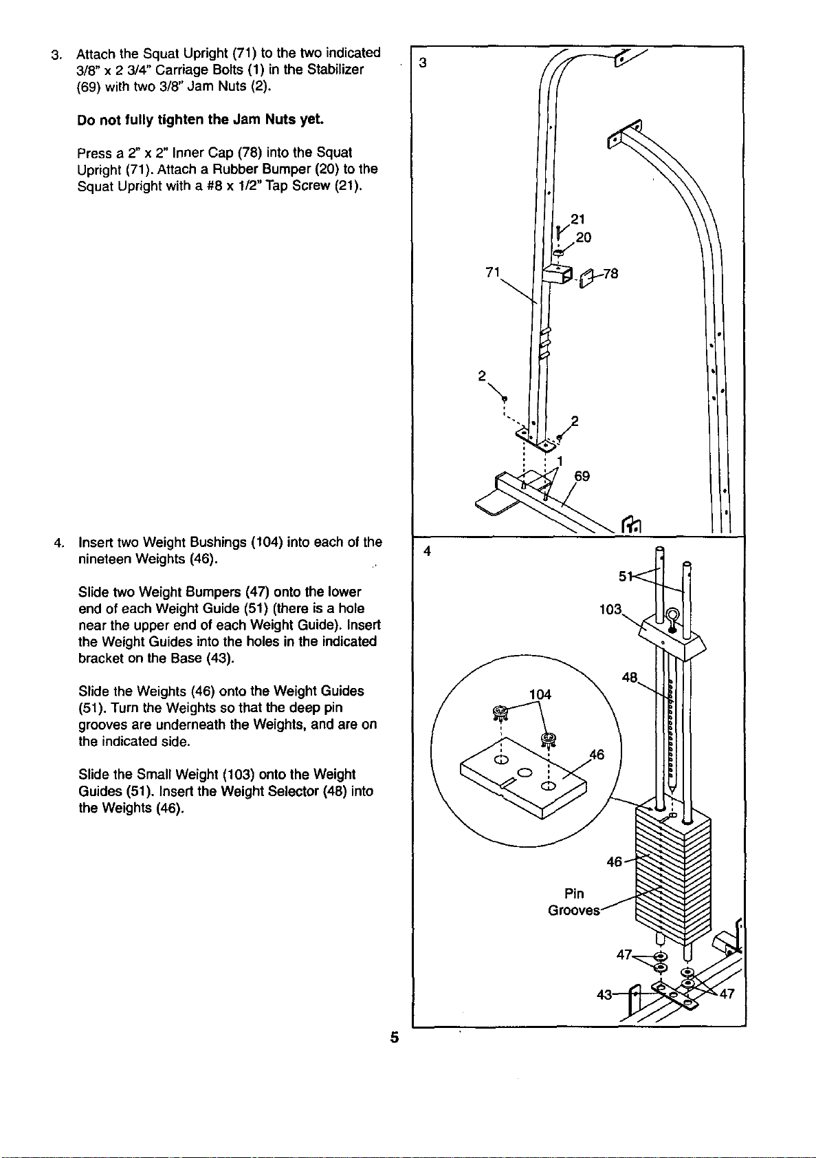
Attach the Squat Upright (71) to the two indicated
3/8" x 2 3/4" Carriage Bolts (1) in the Stabilizer
(69) with two 3/8" Jam Nuts (2).
Do not fully tighten the Jam Nuts yet.
Press a 2" x 2" Inner Cap (78) into the Squat
Upright (71). Attach a Rubber Bumper (20) to the
Squat Upright with a #8 x 1/2" Tap Screw (21),
Insert two Weight Bushings (104) into each of the
nineteen Weights (46).
Slide two Weight Bumpers (47) onto the lower
end of each Weight Guide (51) (them is a hole
near the upper end of each Weight Guide). Insert
the Weight Guides into the holes in the indicated
bracket on the Base (43).
Slide the Weights (46) onto the Weight Guides
(51). Turn the Weights so that the deep pin
grooves are underneath the Weights, and are on
the indicated side.
Slide the Small Weight (103) onto the Weight
Guides (51). Insert the Weight Selector (48) into
the Weights (46).
71
2\
21
2O
Pin
103_
5
5. 5
8.
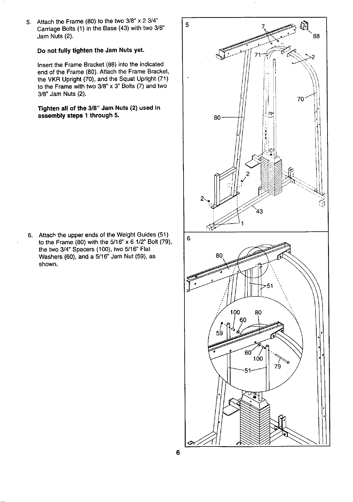
Attach the Frame (80) to the two 3/8" × 2 3/4"
Carriage Bolts (1) in the Base (43) with two 3/8"
Jam Nuts (2).
Do not fully tighten the Jam Nuts yet.
Insert the Frame Bracket (88) into the indicated
end of the Frame (80). Attach the Frame Bracket,
the VKR Upright (70), and the Squat Upright (71)
to the Frame with two 3/8" x 3" Bolts (7) and two
3/8" Jam Nuts (2).
Tighten all of the 3/8" Jam Nuts (2) used in
assembly steps I through 5.
Attach the upper ends of the Weight Guides (51)
to the Frame (80) with the 5/16" x 6 1/2" Bolt (79),
the two 3/4" Spacers (100), two 5/16" Flat
Washers (60), and a 5/16" Jam Nut (59), as
shown.
2-..,e
80
88
6
7,
8.
,
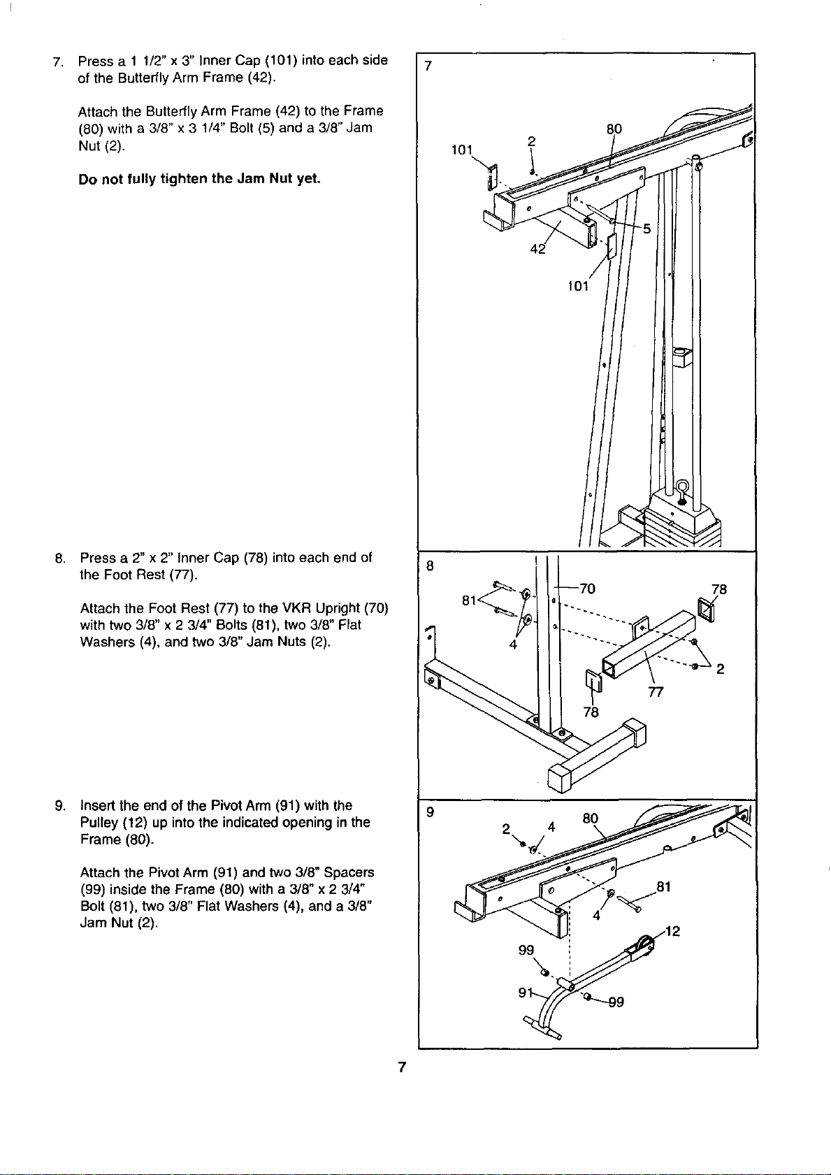
Press a 1 1/2" x 3" Inner Cap (101) into each side
of the Butterfly Arm Frame (42).
Attach the Butterfly Arm Frame (42) to the Frame
(80) with a 3/8" x 3 1/4" Bolt (5) and a 3/8" Jam
Nut (2).
Do not fully tighten the Jam Nut yet.
Press a 2" x 2" Inner Cap (78) into each end of
the Foot Rest (77).
Attach the Foot Rest (77) to the VKR Upright (70)
with two 3/8" x 2 3/4" Bolts (81), two 3/8" Flat
Washers (4), and two 3/8" Jam Nuts (2).
Insert the end of the Pivot Arm (91) with the
Pulley (12) up intothe indicated opening in the
Frame (80).
Attach the Pivot Arm (91) and two 3/8" Spacers
(99) inside the Frame (80) with a3/8" x23/4"
Bolt (81), two 3/8" Flat Washers (4), and a 3/8"
Jam Nut (2).
7
2
101
42
78
2
9
4
, "12
°\.J
7
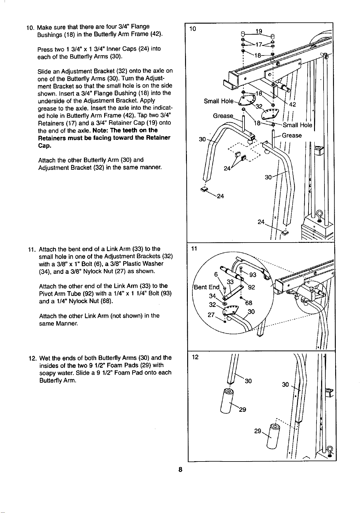
10. Make sure that there are four 3/4" Flange
Bushings (18) in the Butterfly Arm Frame (42).
Press two 1 3/4" x 1 3/4" Inner Caps (24) into
each of the Butterfly Arms (30).
Slide an Adjustment Bracket (32) onto the axle on
one of the Butterfly Arms (30). Turn the Adjust-
ment Bracket so that the small hole is on the side
shown. Insert a 3/4" Flange Bushing (18) into the
underside of the Adjustment Bracket. Apply
grease to the axle. Insert the axle into the indicat-
ed hole in Butterfly Arm Frame (42). Tap two 3/4"
Retainers (17) and a 3/4" Retainer Cap (19) onto
the end of the axle. Note: The teeth on the
Retainers must be facing toward the Retainer
Cap.
Attach the other Butterfly Arm (30) and
Adjustment Bracket (32) in the same manner.
11. Attach the bent end of a Link Arm (33) to the
small hole in one of the Adjustment Brackets (32)
with a 3/8" x 1" Bolt (6), a 3/8" Plastic Washer
(34), and a 3/8" Nylock Nut (27) as shown.
Attach the other end of the Link Arm (33) to the
Pivot Arm Tube (92) with a 1/4" x 11/4" Bolt (93)
and a 1/4" Nyloek Nut (68).
Attach the other Link Arm (not shown) in the
same Manner.
12. Wet the ends of both Butterfly Arms (30) and the
insides of the two 9 1/2" Foam Pads (29) with
soapy water. Slide a 9 112"Foam Pad onto each
Butterfly Arm.
10
11
12
8
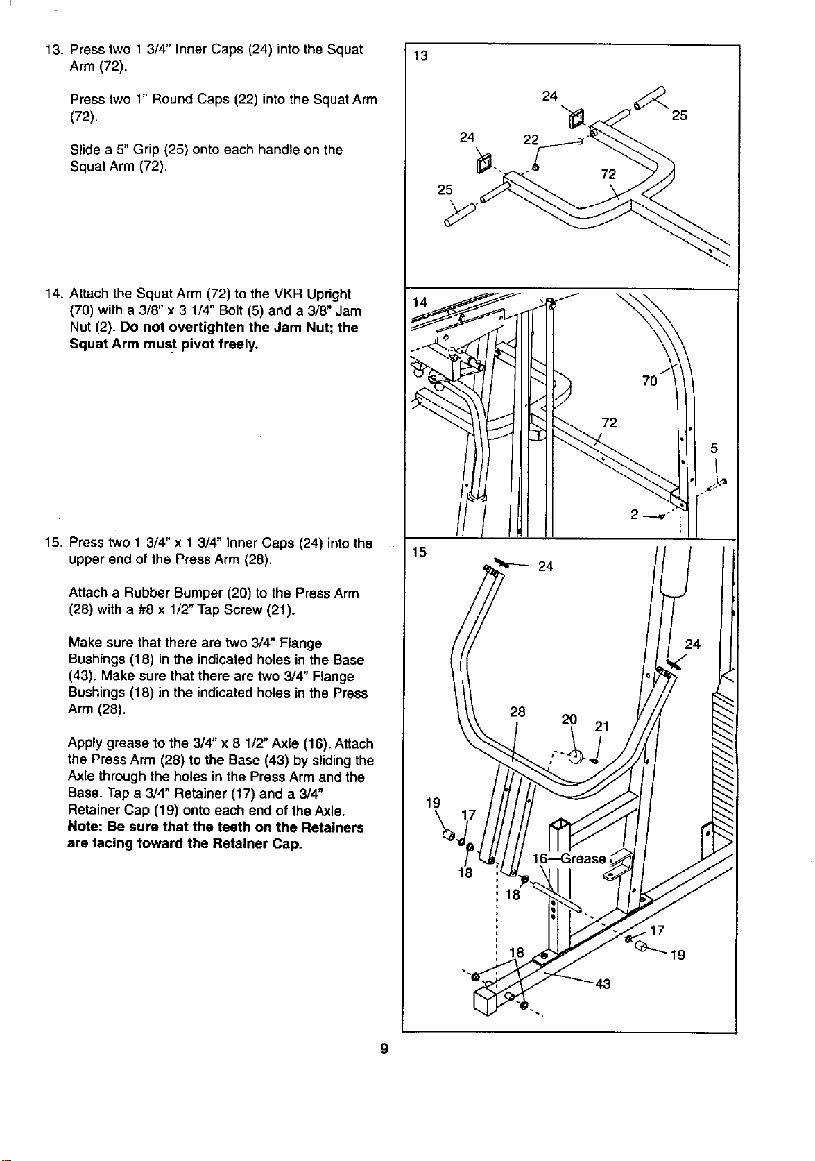
13. Press two 1 3/4" Inner Caps (24) into the Squat
Arm (72).
Press two 1" Round Caps (22) into the Squat Arm
(72).
Slide a 5" Grip (25) onto each handle on the
Squat Arm (72).
14. Attach the Squat Arm (72) to the VKR Upright
(70) with a 3/8" x 3 1/4" Bolt (5) and a 3/8" Jam
Nut (2). Do not overtighten the Jam Nut; the
Squat Arm must pivot freely.
15. Press two 1 3/4" x13/4" Inner Caps (24) intothe
upper end of the Press Arm (28).
Attach a Rubber Bumper (20) to the Press Arm
(28) with a #8 x 1/2" Tap Screw (21).
Make sure that there are two 3/4" Flange
Bushings (18) in the indicated holes in the Base
(43). Make sure that there are two 3/4" Flange
Bushings (18) in the indicated holes in the Press
Arm (28).
Apply grease to the 3/4" x 8 1/2" Axle (16). Attach
the Press Arm (28) to the Base (43) by sliding the
Axle through the holes in the Press Arm and the
Base. Tap a 3/4" Retainer (17) and a 3/4"
Retainer Cap (19) onto each end of the Axle.
Note: Be sure that the teeth on the Retainers
are facing toward the Retainer Cap.
13
15
24
25
19
18
24
22
2O
18
18
21
25
43
9
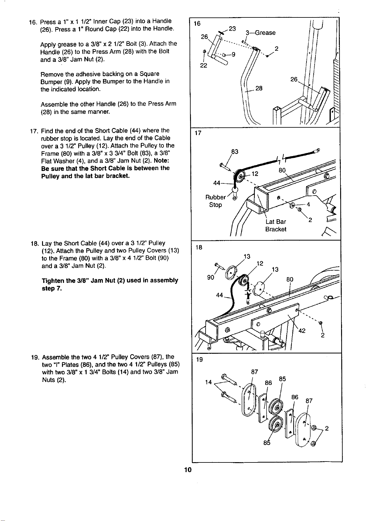
16. Press a 1" x 1 1/2" Inner Cap (23) into a Handle
(26). Press a 1" Round Cap (22) into the Handle.
Apply grease to a 3/8" x 2 1/2" Bolt (3). Attach the
Handle (26) to the Press Arm (28) with the Bolt
and a 3/8" Jam Nut (2).
Remove the adhesive backing on a Square
Bumper (9). Apply the Bumper to the Handle in
the indicated location.
Assemble the other Handle (26) to the Press Arm
(28) in the same manner.
17. Find the end of the Short Cable (44) where the
rubber stop is located. Lay the end of the Cable
over a 3 1/2" Pulley (12). Attach the Pulley to the
Frame (80) with a 3/8" x 3 3/4" Bolt (83), a 3/8"
Flat Washer (4), and a 3/8" Jam Nut (2). Note:
Be sure that the Short Cable is between the
Pulley and the lat bar bracket.
18. Lay the Short Cable (44) over a 3 1/2" Pulley
(12). Attach the Pulley and two Pulley Covers (13)
to the Frame (80) with a 3/8" x 4 1/2" Bolt (90)
and a 3/8" Jam Nut (2).
Tighten the 3/8" Jam Nut (2) used in assembly
step 7.
19. Assemble the two 4 1/2" Pulley Covers (87), the
two =1"Plates (86), and the two 4 1/2" Pulleys (85)
with two 3/8" x 1 3/4" Bolts (14) and two 3/8" Jam
Nuts (2).
16
22
17
18
19
3--Grease _J
83 60
Stop
Lat Bar
Bracket
13 12 13
80
2
14
87
86 85
86 87
10
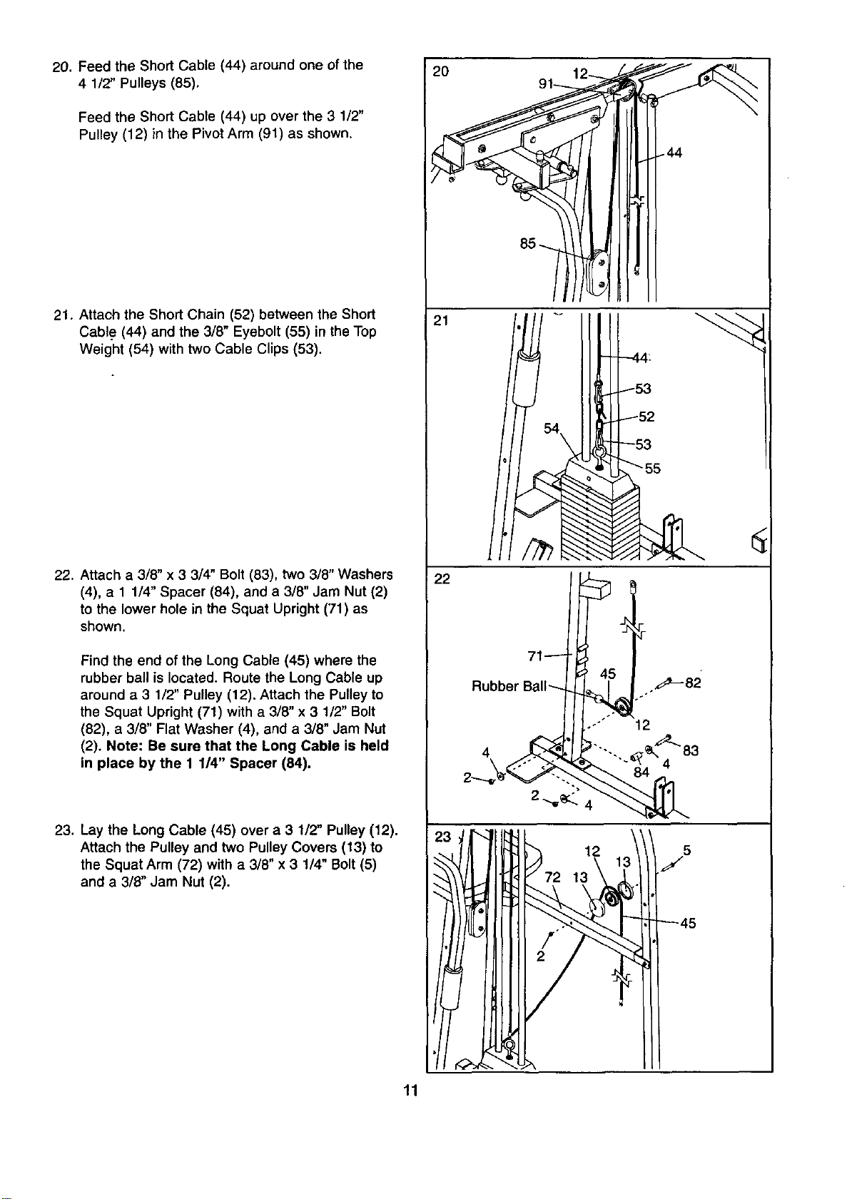
20. Feed the Short Cable (44) around one of the
4 1/2" Pulleys (85),
Feed the Short Cable (44) up over the 3 1/2"
Pulley (12) in the Pivot Arm (91) as shown,
21. Attach the Short Chain (52) between the Short
Cable (44) and the 3/8" Eyebolt (55) in the Top
Weight (54) with two Cable Clips (53).
22. Attach a 3/8" x 3 3/4" Bolt (83), two 3/8" Washers
(4), a 1 1/4" Spacer (84), and a 3/8" Jam Nut (2)
to the lower hole in the Squat Upright (71) as
shown.
Find the end of the Long Cable (45) where the
rubber ball is located. Route the Long Cable up
around a 3 1/2" Pulley (12). Attach the Pulley to
the Squat Upright (71) with a 3/8" x 3 1/2" Bolt
(82), a 3/8" Flat Washer (4), and a 3/8" Jam Nut
(2), Note: Be sure that the Long Cable is held
in place by the 1 1/4" Spacer (84).
23. Lay the Long Cable (45) over a 3 1/2" Pulley (12).
Attach the Pulley and two Pulley Covers (13) to
the Squat Arm (72) with a 3/8" x 3 1/4" Bolt (5)
and a 3/8" Jam Nut (2).
20
21
-44:
22
Rubber E
4
12 5
J
13
11
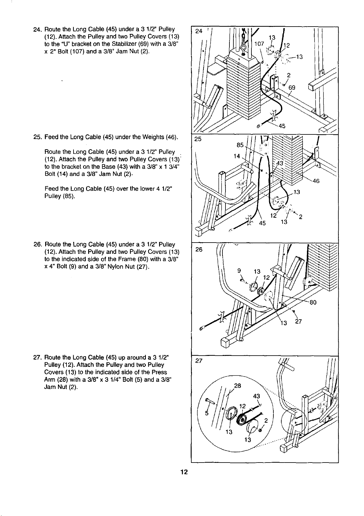
24. Route the Long Cable (45) under a 3 1/2" Pulley
(12). Attach the Pulley and two Pulley Covers (13)
to the "U" bracket on the Stabilizer (69) with a 3/8"
x 2" Bolt (107) and a 3/8" Jam Nut (2).
25. Feed the Long Cable (45) under the Weights (46).
Route the Long Cable (45) under a 3 1/2" Pulley .
(12). Attach the Pulley and two Pulley Covers (13)
to the bracket on the Base (43) with a 3/8" x 1 3/4"
Bolt (14) and a 3/8" Jam Nut (2).
Feed the Long Cable (45) over the lower 4 1/2"
Pulley (85).
26. Route the Long Cable (45) under a 3 1/2" Pulley
(12). Attach the Pulley and two Pulley Covers (13)
to the indicated side of the Frame (80) with a 3/8"
x 4" Bolt (9) and a 3/8" Nylon Nut (27).
27. Route the Long Cable (45) up around a 3 1/2"
Pulley (12), Attach the Pulley and two Pulley
Covers (13) to the indicated side of the Press
Arm (28) with a 3/8" x 3 1/4" Bolt (5) and a 3/8"
Jam Nut (2).
24'I
iJ
14. i'i
13! ;
l "_J_'_ °_13 ,
:43"-, _f/-
Y?,.
/ 2
13
26 '/I
13
)
27
28 .,
12
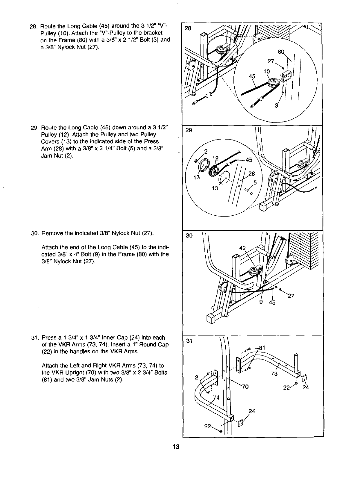
28. Route the Long Cable (45) around the 3 1/2" "V"-
Pulley (10). Attach the "V"-Pulley to the bracket
on the Frame (80) with a 3/8" x 2 1/2" Bolt (3) and
a 3/8" Nylock Nut (27).
29. Route the Long Cable (45) down around a 3 1/2"
Pulley (12). Attach the Pulley and two Pulley
Covers (13) to the indicated side of the Press
Arm (28) with a 3/8" x 3 1/4" Bolt (5) and a 3/8"
Jam Nut (2).
30. Remove the indicated 3/8" Nylock Nut (27).
Attach the end of the Long Cable (45) to the indi-
cated 3/8" x 4" Bolt (9) in the Frame (80) with the
3/8" Nylock Nut (27).
31. Press a 1 3/4" x 1 3/4" Inner Cap (24) into each
of the VKR Arms (73, 74). Insert a 1" Round Cap
(22) in the handles on the VKR Arms.
Attach the Left and Right VKR Arms (73, 74) to
the VKR Upright (70) with two 3/8" x 2 3/4" Bolts
(81) and two 3/8" Jam Nuts (2).
28
29
13
42
31
•_" 81 '24
22..
13
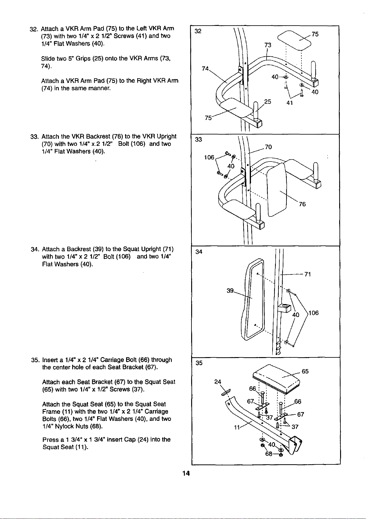
32. Attach aVKR Arm Pad (75) to the Left VKR Arm
(73) with two 1/4" x 2 1/2" Screws (41) and two
1/4" Flat Washers (40).
Slide two 5" Grips (25) onto the VKR Arms (73,
74).
Attach a VKR Arm Pad (75) to the Right VKR Arm
(74) in the same manner.
33. Attach the VKR Backrest (76) to the VKR Upright
(70) with two 1/4" x.2 1/2" Bolt (106) and two
114"Flat Washers (40).
34. Attach a Backrest (39) to the Squat Upright (71)
with two 1/4" x 2 1/2" Bolt (106) and two 1/4"
Flat Washers (40).
35. Insert a 1/4" x 2 1/4" Carriage Bolt (66) through
the center hole of each Seat Bracket (67).
Attach each Seat Bracket (67) to the Squat Seat
(65) with two 114"x 112"Screws (37).
Attach the Squat Seat (65) to the Squat Seat
Frame (11) with the two 1/4" x 2 1/4" Carriage
Bolts (66), two 1/4" Flat Washers (40), and two
1/4" Nylock Nuts (68).
Press a 1 3/4" x 1 314"insert Cap (24) into the
Squat Seat (11).
32
73
25 41
33
106_
34
35
39-_.
106
24
65
14
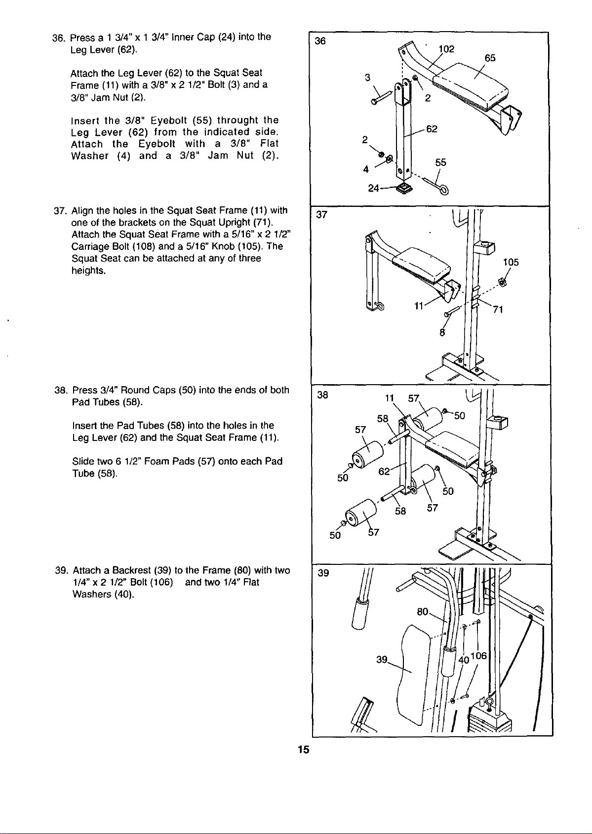
36. Press a 1 3/4" x 1 3/4" Inner Cap (24) into the
Leg Lever (62).
Attach the Leg Lever (62) to the Squat Seat
Frame (11) with a 3/8" x 2 1/2" Bolt (3) and a
3/8" Jam Nut (2).
Insert the 3/8" Eyebolt (55) throught the
Leg Lever (62) from the indicated side.
Attach the Eyebolt with a 318" Flat
Washer (4) and a 3/8" Jam Nut (2).
37. Align the holes in the Squat Seat Frame (11) with
one of the brackets on the Squat Upright (71).
Attach the Squat Seat Frame with a 5/16" x 2 112"
Carriage Bolt (108) and a 5/16" Knob (105). The
Squat Seat can be attached at any of three
heights.
38. Press 3/4" Round Caps (50) into the ends of both
Pad Tubes (58).
Insert the Pad Tubes (58) into the holes in the
Leg Lever (62) and the Squat Seat Frame (11).
Slide two 6 1/2" Foam Pads (57) onto each Pad
Tube (58).
39. Attach a Backrest (39) to lhe Frame (80) with two
1/4" x 2 1/2" Bolt (106) and two 1/4" Flat
Washers (40).
36
37
38
50
50
39
102 65
3
2
4 55
105
o e ÷#
8
11
58
57
58
15
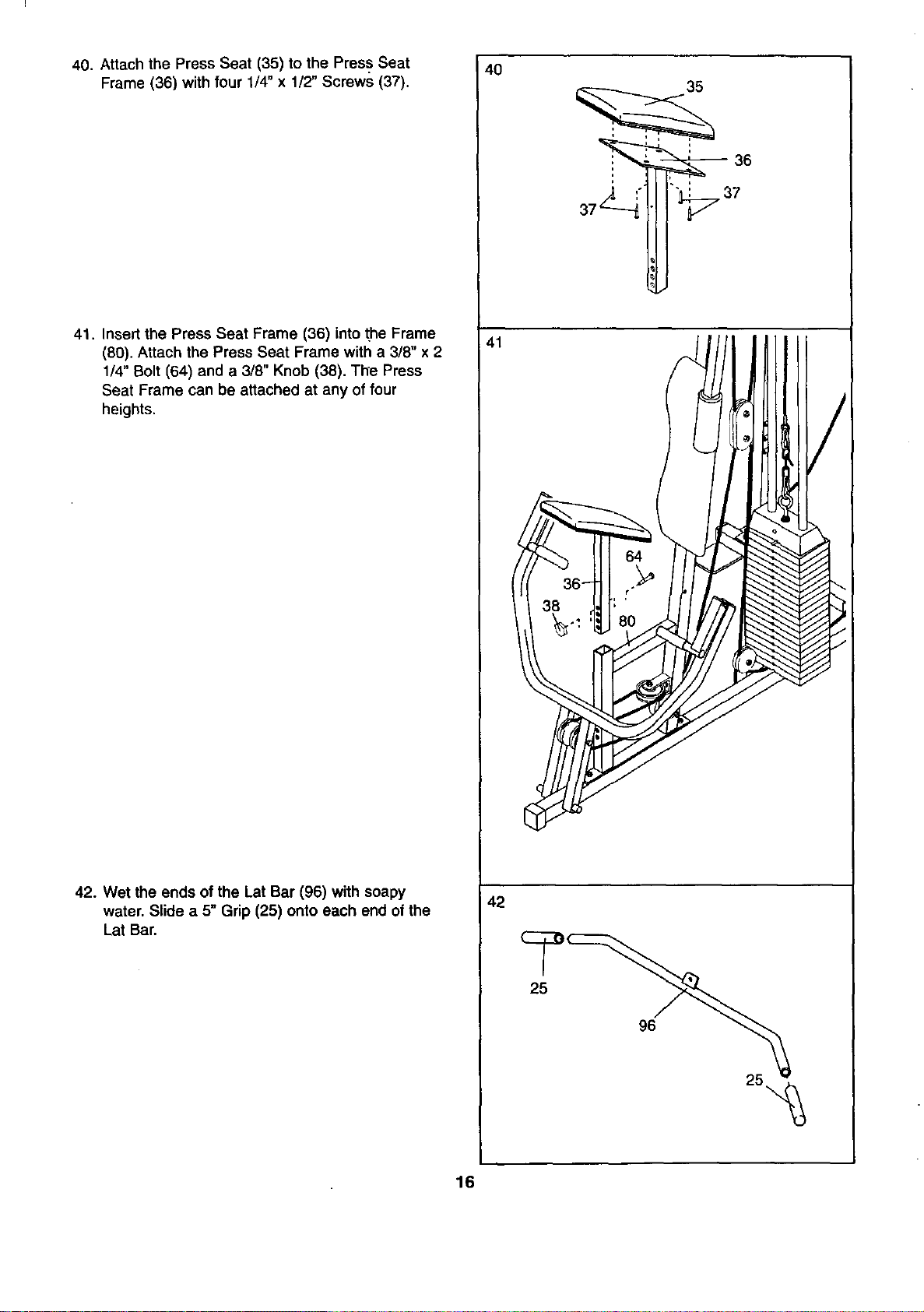
40. Attach the Press Seat (35) to the Press Seat
Frame (36) with four 1/4" x1/2" Screws (37).
41. Insert the Press Seat Frame (36) into the Frame
(80). Attach the Press Seat Frame with a3/8" x2
1/4" Bolt (64) and a 3/8" Knob (38). The Press
Seat Frame can be attached at any of four
heights.
42. Wet the ends of the Lat Bar (96) with soapy
water. Slide a 5" Grip (25) onto each end of the
Lat Bar.
4O
41
42
35
25
96
16
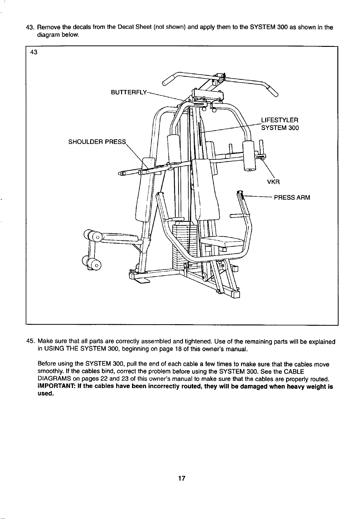
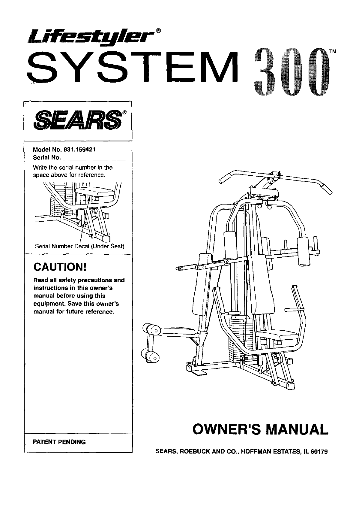
43. Remove the decals from the Decal Sheet (not shown) and apply them to the SYSTEM 300 as shown in the
diagram below.
43
LIFESTYLER
SHOULDER PRESS_
VKR
-PRESS ARM
45. Make sure that all parts are correctly assembled and tightened. Use of the remaining parts will be explained
in USING THE SYSTEM 300, beginning on page 18 of this owner's manual.
Before using the SYSTEM 300, pull the end of each cable afew times to make sure that the cables move
smoothly. If the cables bind, correct the problem before using the SYSTEM 300. See the CABLE
DIAGRAMS on pages 22 and 23 of this owner's manual to make sure that the cables are properly routed.
IMPORTANT: If the cables have been incorrectly routed, they will be damaged when heavy weight is
used.
17
USING THE SYSTEM 300
The instructions below describe how each part of the SYSTEM 300 can be adjusted. Refer to the EXERCISE
GUIDE accompanying this owner's manual for exercise guidelines, and to see how the SYSTEM 300 should be
set up for each exercise.
IMPORTANT: When attaching the lat bar or nylon strap, make sure that the attachments are in the cor-
rect starting position for the exercise to be performed. If there is any slack in the cable or chain as an
exercise is performed, the effectiveness of the exercise will be reduced.
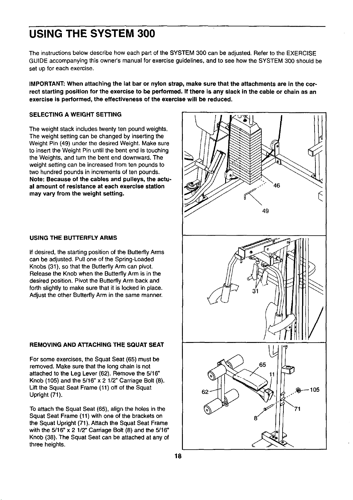
SELECTING A WEIGHT SETTING
The weight stack includes twenty ten pound weights.
The weight setting can be changed by inserting the
Weight Pin (49) under the desired Weight. Make sure
to insert the Weight Pin until the bent end is touching
the Weights, and turn the bent end downward. The
weight setting can be increased from ten pounds to
two hundred pounds in increments of ten pounds.
Note: Because of the cables and pulleys, the actu-
al amount of resistance at each exercise station
may vary from the weight setting.
49
USING THE BUTTERFLY ARMS
If desired, the starting position of the ButterflyArms
can be adjusted. Pull one of the Spring-Loaded
Knobs (31), so that the Butterfly Arm can pivot.
Release the Knob when the Butterfly Arm is in the
desired position. Pivot the Butterfly Arm back and
forth slightly to make sure that it is locked in place.
Adjust the other Butterfly Arm in the same manner. 31
REMOVING AND ATTACHING THE SQUAT SEAT
For some exercises, the Squat Seat (65) must be
removed. Make sure that the long chain is not
attached to the Leg Lever (62). Remove the 5/16"
Knob (105) and the 5/16" x 2 1/2" Carriage Bolt (8).
Lift the Squat Seat Frame (11) off of the Squat
Upright (71).
To attach the Squat Seat (65), align the holes in the
Squat Seat Frame (11) with one of the brackets on
the Squat Upright (71). Attach the Squat Seat Frame
with the 5/16" x 2 1/2" Carriage Bolt (8) and the 5/16"
Knob (38). The Squat Seat can be attached at any of
three heights.
18
65
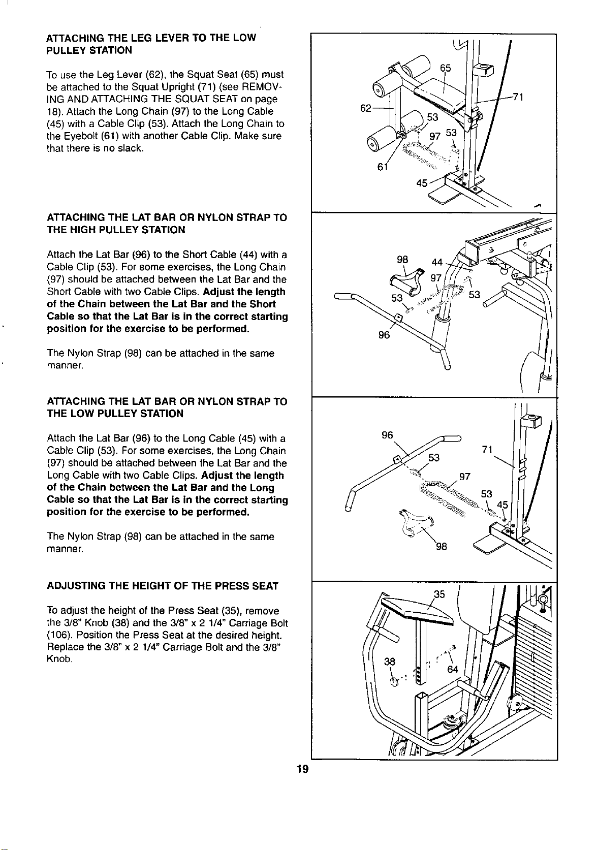
ATTACHING THE LEG LEVER TO THE LOW
PULLEY STATION
To use the Leg Lever (62), the Squat Seat (65) must
be attached to the Squat Upright (71) (see REMOV-
ING AND ATTACHING THE SQUAT SEAT on page
18). Attach the Long Chain (97) to the Long Cable
(45) with a Cable Clip (53). Attach the Long Chain to
the Eyebolt (61) with another Cable Clip. Make sure
that there is no slack.
ATTACHING THE LAT BAR OR NYLON STRAP TO
THE HIGH PULLEY STATION
Attach the Lat Bar (96) to the Short Cable (44) with a
Cable Clip (53). For some exercises, the Long Chain
(97) should be attached between the Lat Bar and the
Short Cable with two Cable Clips. Adjust the length
of the Chain between the Lat Bar and the Short
Cable so that the Lat Bar is in the correct starting
position for the exercise to be performed,
The Nylon Strap (98) can be attached in the same
manner.
ATTACHING THE LAT BAR OR NYLON STRAP TO
THE LOW PULLEY STATION
Attach the Lat Bar (96) to the Long Cable (45) with a
Cable Clip (53). For some exercises, the Long Chain
(97) should be attached between the Lat Bar and the
Long Cable with two Cable Clips. Adjust the length
of the Chain between the Lat Bar and the Long
Cable so that the Lat Bar is in the correct starting
position for the exercise to be performed.
The Nylon Strap (98) can be attached in the same
manner.
ADJUSTING THE HEIGHT OF THE PRESS SEAT
To adjust the height of the Press Seat (35), remove
the 3/8" Knob (38) and the 3/8" x 2 1/4" Carriage Bolt
(106). Position the Press Seat at the desired height.
Replace the 3/8" x 2 1/4" Carriage Bolt and the 3/8"
Knob.
61
98
53
96
19
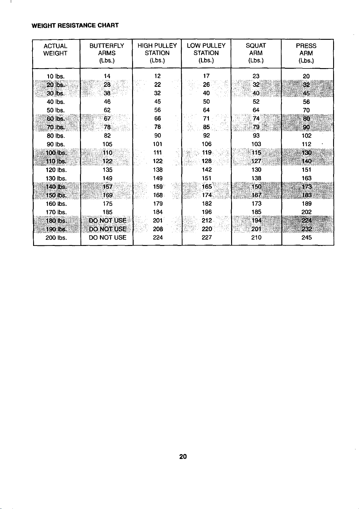
WEIGHT RESISTANCE CHART
ACTUAL BUTTERFLY HIGH PULLEY LOW PULLEY SQUAT PRESS
WEIGHT ARMS STATION STATION ARM ARM
(Lbs.) (Lbs,) (Lbs.) (Lbs,) (Lbs.)
10 Ibs. 14 12 17 23 20
22 26 32"_!i! _i_
32 40
40 Ibs. 46 45 50 52 56
50 Ibs. 62 56 64 64 70
66
78
80 Ibs. 82 90 92 93 102
90 Ibs. 105 101 106 103 112
111
122
120 Ibs. 135 138 142 130 151
130 Ibs. 149 149 151 138 163
160 Ibs. 175 179 182 173 189
170 Ibs. 185 184 196 185 202
212
208 220
200 Ibs. DO NOT USE 224 227 210 245
20
TROUBLE-SHOOTING AND MAINTENANCE
Inspect and tighten all parts each time you use the SYSTEM 300. Replace all worn parts immediately (see
ORDERING REPLACEMENT PARTS on the back cover of this owner's manual). The SYSTEM 300 can be
cleaned using a damp cloth and a mild detergent. Do not use solvents or abrasives.
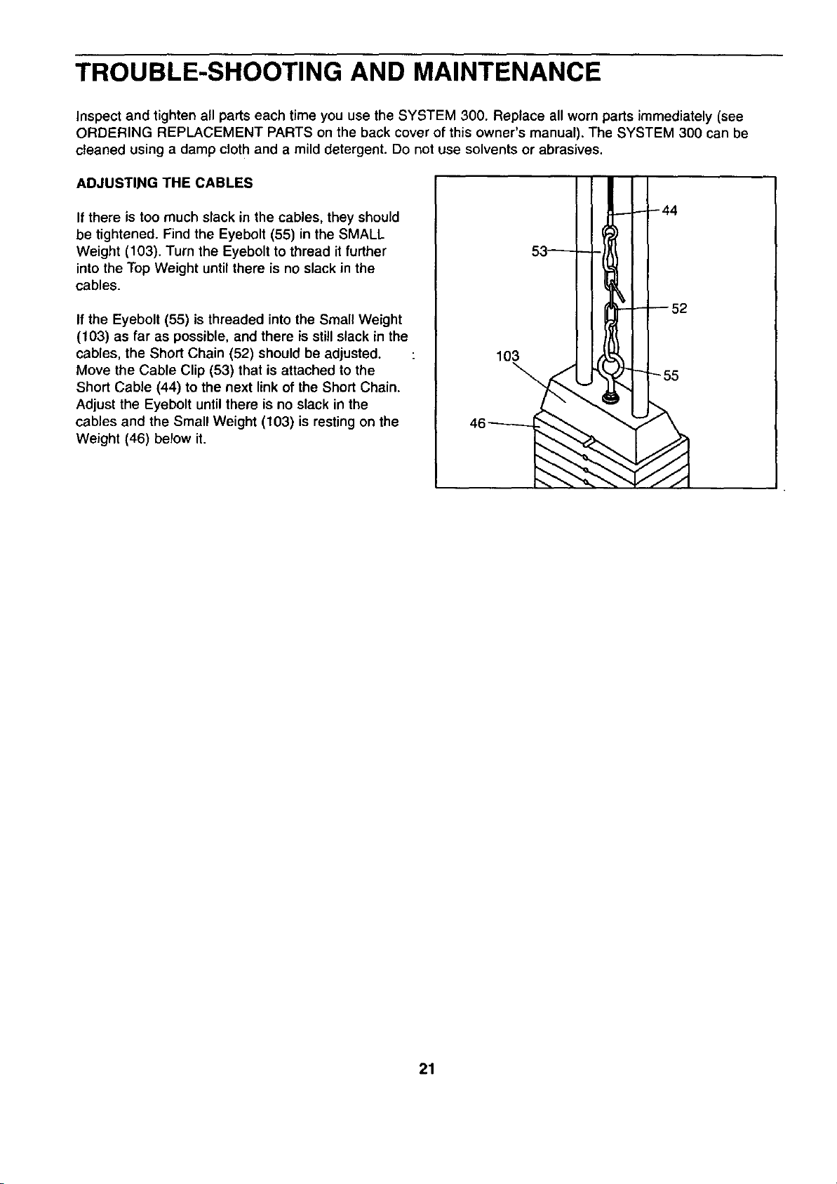
ADJUSTING THE CABLES
If there is too much slack in the cables, they should
be tightened. Find the Eyebolt (55) in the SMALL
Weight (103). Turn the Eyebolt to thread it further
into the Top Weight until there is no slack in the
cables.
If the Eyebolt (55) is threaded into the Small Weight
(103) as far as possible, and there is still slack in the
cables, the Short Chain (52) should be adjusted.
Move the Cable Clip (53) that is attached to the
Short Cable (44) to the next link of the Short Chain.
Adjust the Eyebolt until there is no slack in the
cables and the Small Weight (103) is resting on the
Weight (46) below it.
44
53
52
21
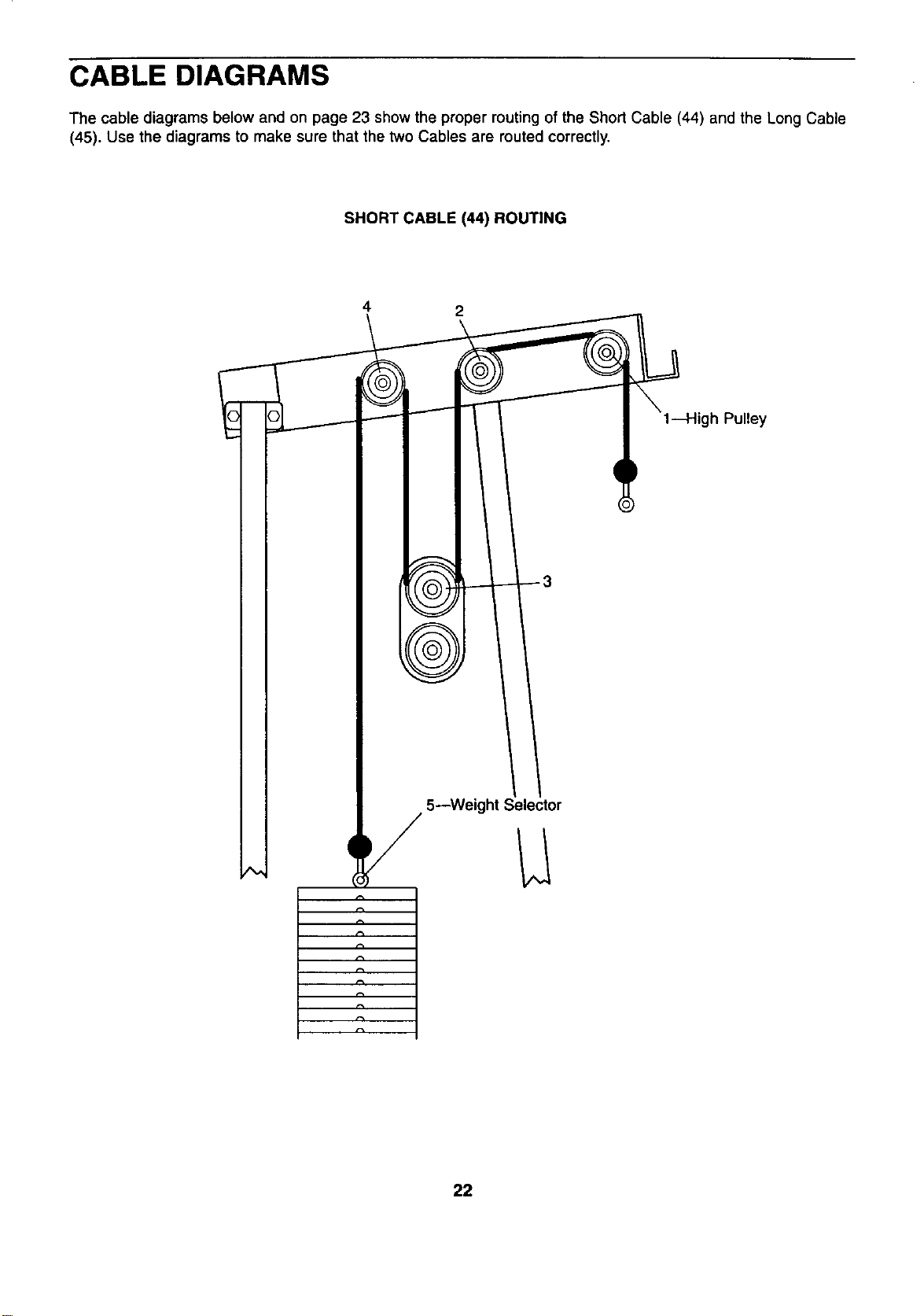
CABLE DIAGRAMS
The cable diagrams below and on page 23 show the proper routing of the Short Cable (44) and the Long Cable
(45). Use the diagrams to make sure that the two Cables are routed correctly.
SHORT CABLE (44) ROUTING
4 2
gh Pulley
5--Weight Selector
22
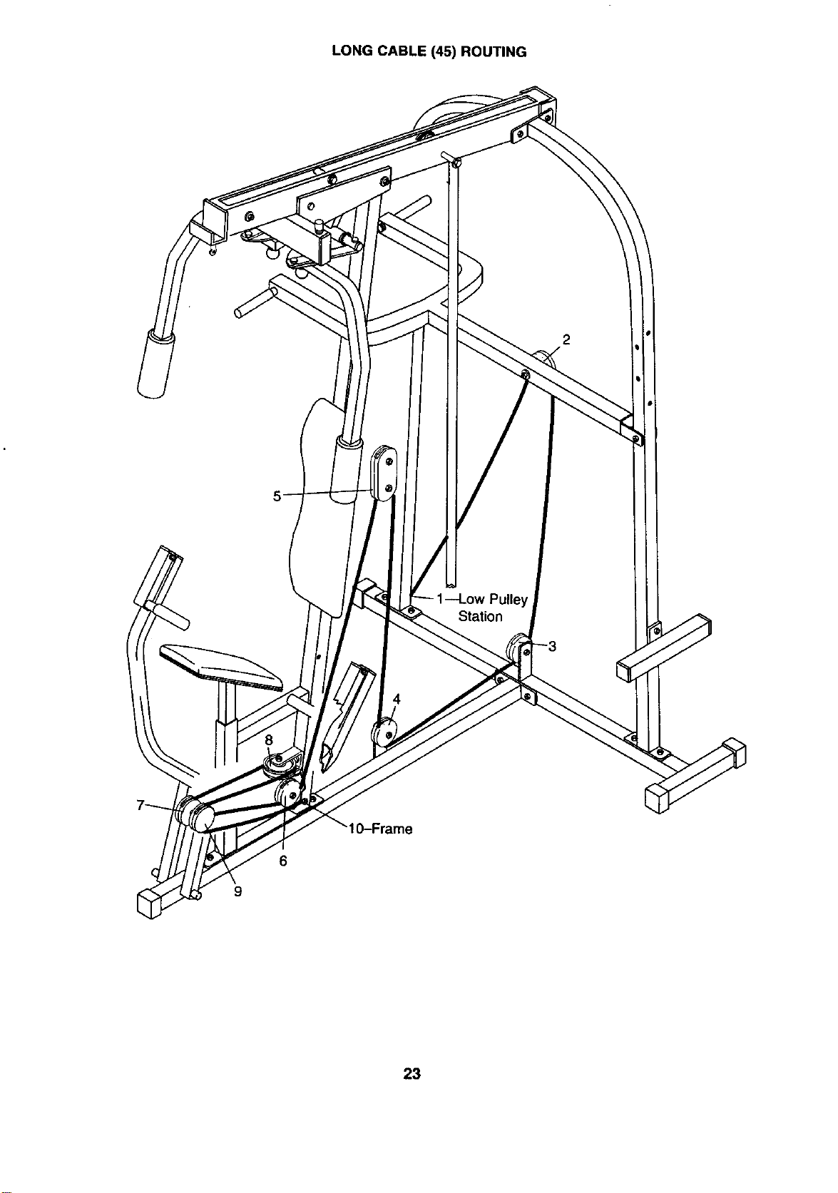
LONG CABLE (45) ROUTING
I
Station
4
_)--Frame
6
9
23
ORDERING REPLACEMENT PARTS
Each SYSTEM 300 has its own MODEL NUMBER. Always mention this MODEL NUMBER when requesting ser-
vice or repair parts for your SYSTEM 300.
All parts listed herein can be ordered through SEARS, ROEBUCK AND CO. SERVICE CENTERS and most
SEARS RETAIL STORES. If parts you need are not stocked locally, your order will be transmitted to a SEARS
PARTS DISTRIBUTION CENTER for handling.
WHEN ORDERING REPAIR PARTS, ALWAYS GIVE THE FOLLOWING INFORMATION:
1. The MODEL NUMBER of the product (831.159421).
2. The NAME of the product. (LIFESTYLER ®SYSTEM 300 Weight System.)
3. The PART NUMBER and DESCRIPTION of the part(s), from the PARTS LIST/EXPLODED DRAWING
accompanying this owner's manual.
Your SYSTEM 300 has added value when you consider that SEARS has service units nationwide, staffed with
SEARS trained technicians specifically trained on SEARS products, having the parts, tools and equipment to
ensure that we meet our pledge to you: "We service what we sell."
Should you ever need repair service or parts, call toll free:
For repair service: 1-800-4-REPAIR (1-800-473-7247)
For repair parts: 1-800-FON-PART (1-800-366-7278)
I FULL 90 DAY WARRANTY I
For 90 days from the date of purchase, when proper assembly and maintenance procedures detailed in
the Owner's Manual are followed, SEARS will, free of charge, repair or replace and install a replacement
part for any defective part, when the SYSTEM 300 is used in a normal manner.
This warranty does not apply when the SYSTEM 300 is used for commercial or rental purposes.
SERVICE IS AVAILABLE SIMPLY BY CONTACTING YOUR NEAREST SEARS SERVICE
CENTER/DEPARTMENT IN THE UNITED STATES.
This warranty gives you specific legal rights, and you may also have other rights which vary from state to
state.
SEARS, ROEBUCK AND CO., DEPT. 817WA,
HOFFMAN ESTATES, IL 60179
Part No. 122425 R994A Printed in Canada © 1994 Sears, Roebuck and Co.