1
Owner’s Manual
8/16-Port NetDirector
®
DisplayPort Rack-Mount
Console KVM Switch
Models: B030-DP08-17D / B030-DP16-17D
1111 W. 35th Street, Chicago, IL 60609 USA • tripplite.com/support
Copyright © 2021 Tripp Lite. All rights reserved.
WARRANTY REGISTRATION
Register your product today and be
automatically entered to win an ISOBAR
®
surge protector in our monthly drawing!
tripplite.com/warranty

2
Table of Contents
1. FCC Information 3
2. User Notice 3
3. Package Contents 4
4. System Requirements 5
4.1 Built-In LCD Console 5
4.2 Optional External Console 5
4.3 Computers 5
4.4 Operating Systems 5
5. Features 6
5.1 Components 6
6. Important Safety 9
Instructions
6.1 General Safety 9
Instructions
6.2 Rack-Mounting 10
Safety Instructions
7. Installation 11
7.1 Standard Rack Mounting 11
7.2 2-Post Rack Mounting 11
7.3 Grounding 11
7.4 KVM Switch Installation 12
7.5 Opening/Closing the 13
Console
7.5.1 Opening Separately 13
7.5.2 Opening Together 15
7.5.3 Opening Precautions 15
7.5.4 Closing the Console 16
8. Basic Operation 18
8.1 LCD OSD Configurations 18
8.1.1 LCD Buttons 18
8.1.2 Adjustment Settings 18
8.1.3 Hot Plugging 19
8.1.4 Hot Plugging KVM Ports 19
8.1.5 Powering Off and 19
Restarting
8.1.6 USB Peripheral Devices 19
8.1.7 Port Selection 19
9. KVM Operation 20
9.1 Local Console 20
9.1.1 Local Console OSD Login 20
9.1.2 Local Console OSD 20
Hotkey Sequence
9.1.3 OSD Main Menu 21
9.1.3.1 OSD Main Menu 21
Headings
9.1.3.2 OSD Navigation 21
9.1.3.3 OSD Functions 21
10. Keyboard Port Operation 27
10.1 Hotkey Port Control
10.1.1 Invoke Hotkey Mode 27
10.1.2 Select the Active Port 27
10.1.3 Auto Scan Mode 28
10.1.4 Skip Mode 28
10.1.5 Computer Keyboard/ 28
Mouse Reset
10.1.6 Hotkey Beeper Control 29
10.1.7 Quick Hotkey Control 29
10.1.8 Port Operating 29
System Control
10.1.9 Set USB Speed 29
10.1.10 Restore Default Values 30
10.2 Hotkey Summary Table 30
11. Keyboard Emulation 31
12. Firmware Upgrade Utility 33
12.1 Introduction 33
12.2 Preparation 33
12.3 Starting the Upgrade 34
12.4 Firmware Upgrade 37
Recovery
13. Specifications and 38
Default Settings
13.1 Specifications 38
13.2 OSD Factory Default 38
Settings
14. Warranty and 39
Product Registration

3
1. FCC Information
2. User Notice
This device complies with part 15 of the FCC Rules. Operation is subject to the following two conditions: (1) This device may
not cause harmful interference, and (2) this device must accept any interference received, including interference that may
cause undesired operation.
Note: This equipment has been tested and found to comply with the limits for a Class A digital device, pursuant to part 15 of
the FCC Rules. These limits are designed to provide reasonable protection against harmful interference when the equipment
is operated in a commercial environment. This equipment generates, uses, and can radiate radio frequency energy and, if
not installed and used in accordance with the instruction manual, may cause harmful interference to radio communications.
Operation of this equipment in a residential area is likely to cause harmful interference in which case the user will be required
to correct the interference at his own expense. The user must use shielded cables and connectors with this equipment. Any
changes or modifications to this equipment not expressly approved by Tripp Lite could void the user’s authority to operate this
equipment.
All information, documentation, and specifications contained in this manual are subject to change without prior notification by
the manufacturer. The manufacturer makes no representations or warranties, either expressed or implied, with respect to the
contents hereof and specifically disclaims any warranties as to merchantability or fitness for any particular purpose. Any of the
manufacturer’s software described in this manual is sold or licensed “as is.” Should the programs prove defective following
their purchase, the buyer (and not the manufacturer, its distributor, or its dealer), assumes the entire cost of all necessary
servicing, repair and any incidental or consequential damages resulting from any defect in the software.
The manufacturer of this system is not responsible for any radio and/or TV interference caused by unauthorized modifications
to this device. It is the responsibility of the user to correct such interference.
The manufacturer is not responsible for any damage incurred in the operation of this system if the correct operational voltage
setting was not selected prior to operation. VERIFY THAT THE VOLTAGE SETTING IS CORRECT BEFORE USE.

4
3. Package Contents
• B030-DP08-17D / B030-DP16-17D Console KVM Switch
• (x2) DisplayPort Cables – 6 ft.
• (x2) USB 2.0 A/B Cables – 6 ft.
• (x1) IEC C13 to NEMA 5-15P Power Cord
• (x1) Grounding Wire
• (x1) Quick Start Guide
• (x1) CD with Owner’s Manual
Check to ensure all components are present and in good order. If anything is missing or was damaged in shipping, contact
your dealer.
Read this manual thoroughly and follow the installation and operation procedures carefully to prevent damage to the switch or
to any other devices on the installation.
Optional Accessories
• N201-Series Cat6 Gigabit Snagless Patch Cables
• P006-Series IEC C13 to NEMA 5-15P Power Cords
• P580-Series DisplayPort Cable with Latches (M/M)

5
4. System Requirements
4.1 Built-In LCD Console
The integrated LCD monitor’s maximum resolution is 1920 x 1080 @ 60 Hz. Ensure all resolution settings of the connected
computers do not exceed the LCD monitor’s maximum resolution.
4.2 Optional External Console
• DisplayPort monitor
• USB keyboard and mouse.
4.3 Computers
The following equipment must be installed on each computer:
• DisplayPort graphics card.
• USB mouse and keyboard ports.
4.4 Operating Systems
OS Version
Windows 2000 and higher
Linux RedHat 9.0 and higher
SuSE 10 and higher
Debian 3.1 and higher
Ubuntu 7.04 and higher
UNIX AIX 4.3 and higher
FreeBSD 5.5 and higher
Sun Solaris 8 and higher
Novell Netware 5.0 and higher
Mac OS 9 and higher
6
5. Features
• DisplayPort Rack-Mount Console KVM Switch in a dual-rail housing with top and bottom clearance for integrated operation in
1U of rack space.
• KVM console combines a 17.3” LCD monitor, keyboard and touchpad.
• Multi-platform support; compatible with Windows
®
, Mac
®
, Linux
®
and Sun.
• A single console controls up to 8 or 16 computers.
• External console ports located on the rear of the device enable management of computers connected to the LCD KVM
switch from an external console (USB keyboard, DisplayPort monitor and USB mouse).
• Console lock enables the console modules to remain securely locked away in position when not in use.
• Graphical OSD and graphical toolbars for convenient, user-friendly operation.
• Broadcast Mode support – Keyboard commands can be broadcast to all available computers in the installation.
• HDCP Support on Local Monitor and second Console Port
• Superior video quality – 1920 x 1080 @ 60 Hz; DDC, DDC2, DDC2B
• Auto Scan Mode for monitoring all computers
• Upgradable firmware
• Mac/Sun keyboard support and emulation
• Multilingual OSD supports English, German, Japanese, Traditional Chinese and Simplified Chinese
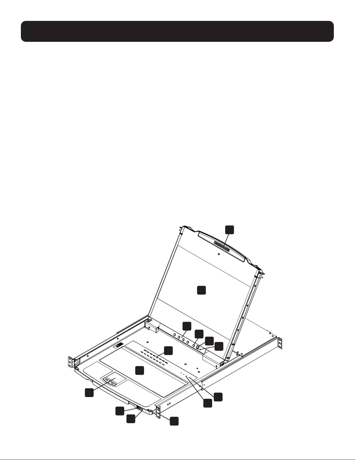
5.1 Components
1
2
3
4
14
13
10
11
12
5
6
7
8
9

7
5. Features
No. Component Description
1
Handle Pull to slide the LCD module out; push to slide it in.
2
LCD Module
After sliding the LCD module out, flip up the cover to access the LCD
display.
3
LCD Controls Buttons that control the position and picture settings of the LCD display.
4
LCD On / Off Button
Push this button to turn the LCD monitor on and off. The button illuminates
when the LCD monitor is off.
Note: The light indicates that only the monitor is off, not the attached KVM switch.
5
Port LEDs / Port Switches
An orange ONLINE LED lights to indicate that the computer attached to
its corresponding port is up and running. A green Selected LED lights to
indicate that the computer attached to the corresponding port is selected
for KVM control.
Press the port pushbuttons to bring the KVM focus to the computer
attached to the corresponding port.
6
Keyboard Module Standard 99-key keyboard.
7
Touchpad Standard mouse touchpad.
8
USB Port
The USB 1.1 hub port connects a USB peripheral device (flash drive, CD-
ROM drive, etc.) to the console or a USB mouse for users who prefer to use
an external mouse.
9
Power LED Lights (green) to indicate that the unit is receiving power.
10
Rack Mounting Tabs Rack-mounting tabs are located at each corner of the device.
11
Lock LEDs The Num Lock, Caps Lock, Scroll Lock LEDs are located here.
12
Reset Switch
This switch is located to the right of the Lock LEDs. Press the recessed
switch in with a thin object to perform a system reset.
13
Firmware Upgrade Switch
During normal operation and while performing a firmware upgrade, this
switch should be in the Normal position. If a firmware upgrade operation
does not complete successfully, this switch is used to perform a firmware
upgrade recovery.
14
Firmware Upgrade Port
The firmware upgrade cable that transfers the firmware upgrade data from
the administrator’s computer plugs into this RJ-11 connector.
8
5. Features
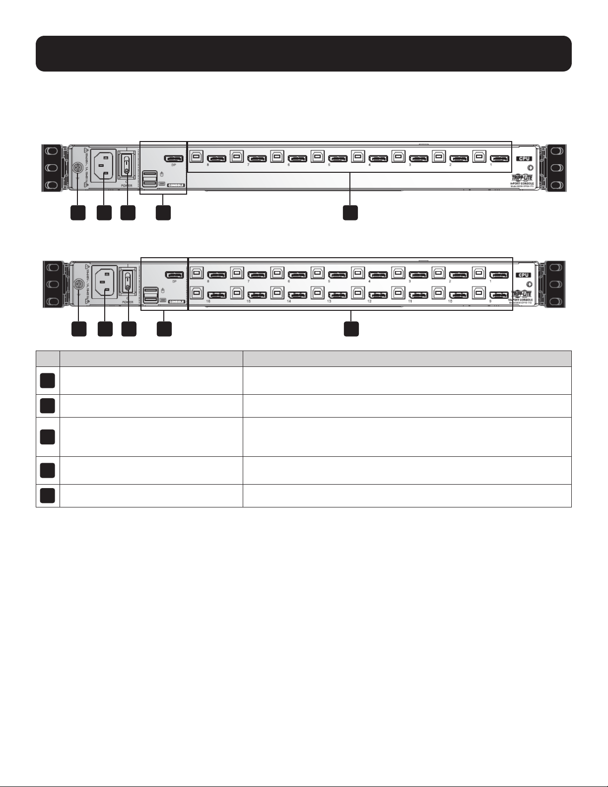
Rear View
Model B030-DP08-17D
Model B030-DP16-17D
No. Component Description
1
Power Socket
Standard 3-prong AC power socket. The power cord from an AC source
plugs in here.
2
Power Switch Standard rocker switch that powers the device on and off.
3
External Console Section
Supports an independent, external KVM console for flexibility and
convenience. The external console's USB keyboard, mouse and DisplayPort
monitor plug in here.
4
KVM Port Section
Connects the device’s ports to computers/servers using DisplayPort and
USB cables.
5
Grounding Terminal The included grounding wire attaches here.
4
4
2
2
1
1
5
5
3
3

9
6. Important Safety Instructions
6.1 General Safety Instructions
• Read all of these instructions and save them for future reference.
• Follow all warnings and instructions marked on the device.
• Do not place the device on any unstable surface. If the device falls, serious damage will result.
• Do not use the device near water.
• Do not place the device near or over, radiators or heat registers.
• The device cabinet is provided with slots and openings to allow for adequate ventilation. To ensure reliable operation and
protect against overheating, these openings should never be blocked or covered.
• The device should never be placed on a soft surface such as a bed, sofa of rug. Doing so will block the device’s ventilation
openings. Moreover, the device should not be placed in a built-in enclosure unless adequate ventilation has been provided.
• Never spill liquid of any type on the device.
• Unplug the device from the wall outlet before cleaning. Use a damp cloth for cleaning. Do not use liquid or aerosol cleaners.
• The device should be operated from the power source indicated on the marking label. If uncertain of the power available,
consult your dealer or local power company.
• The device is designed for IT power distribution systems up to 230V phase-to-phase voltage.
• As an added safety feature, the device is equipped with a 3-wire grounding type plug. If unable to insert the plug into the
outlet, contact an electrician to replace the obsolete outlet. Do not attempt to plug into a two-prong ungrounded outlet.
Always follow local/national wiring codes.
• Do not allow anything to rest on the power cord or cables. Route the power cord and cables to avoid them being stepped on
or tripped over.
• If an extension cord is used with this device, ensure the total ampere ratings of all products used on the extension cord
do not exceed its rated ampere rating. Also ensure all products plugged into the wall outlet does not exceed a total of 15
amperes.
• Consideration should be given to the connection of equipment and the supply circuit, as well as what effect overloading the
supply circuit might have on overcurrent protection and supply wiring.
• To help protect the system from unexpected transient increases and decreases in electrical power, use a Tripp Lite Surge
Protector, Line Conditioner, or Uninterruptible Power Supply (UPS).
• Position system cables and power cables carefully so nothing rests on any cables.
• When connecting or disconnecting power to hot pluggable power supplies, observe the following guidelines:
o Install the power supply before connecting the power cable to the power supply.
o Unplug the power cable before removing the power supply.
o If the system has multiple sources of power, disconnect power from the system by unplugging all power cables from the
power supplies.
• Never push objects of any kind into or through cabinet slots. They may touch dangerous voltage points or short out parts
resulting in a risk of fire or electrical shock.
• Do not attempt to service the device; refer all servicing to qualified service personnel.
• If the following conditions occur, unplug the device from the wall outlet and bring it to qualified service personnel for repair:
o The power cord or plug has become damaged or frayed.
o Liquid has been spilled into the device.
o The device has been exposed to rain or water.
o The device has been dropped, or the cabinet has been damaged.
o The device exhibits a distinct change in performance, indicating a need for service.
o The device does not operate normally when the operating instructions are followed.

10
6. Important Safety Instructions
• Only adjust controls covered in the operating instructions. Improper adjustment of other controls may result in damage that
will require extensive work by a qualified technician to repair.
• Use of this equipment in life support applications where failure of this equipment can reasonably be expected to cause the
failure of the life support equipment or to significantly affect its safety or effectiveness is not recommended. Do not use this
equipment in the presence of a flammable anesthetic mixture with air, oxygen or nitrous oxide.
6.2 Rack-Mounting Safety Instructions
• The ambient operating temperature in the rack may be an issue and is dependent upon the rack load and ventilation. When
installing in a closed or multi-device rack assembly, ensure the temperature will not exceed the maximum rated ambient
temperature.
• Before installing the rack, ensure the stabilizers are secured to the rack, extended to the floor and the full weight of the rack
rests on the floor. Install front and side stabilizers on a single rack or front stabilizers for joined multiple racks before working
on the rack.
• Always load the rack from the bottom up with the heaviest item loaded into the rack first.
• When loading the rack, avoid creating a hazardous condition due to uneven loading.
• Ensure the rack is level and stable before extending a device from the rack.
• Use caution when pressing the rail release latches or sliding a device into or out of a rack; slide rails can pinch your fingers.
• After a device is inserted into the rack, carefully extend the rail into a locking position, then slide the device into the rack.
• Do not overload the AC supply branch circuit that provides power to the rack. The total rack load should not exceed 80
percent of the branch circuit rating.
• Ensure that proper airflow is provided to devices in the rack.
• Do not step on or stand on any device when servicing other devices in a rack.
• Do not connect the RJ11 connector marked “Upgrade” to a public telecommunication network.
• Caution! Slide/Rail (LCD KVM) mounted equipment is not to be used as a shelf or work space.
11
7. Installation
The B030-DP08-17D / B030-DP16-17D is designed for mounting in a 1U rack system. For convenience, a rack mounting kit
is included for quick installation. The various mounting options are explained in the following subsections.
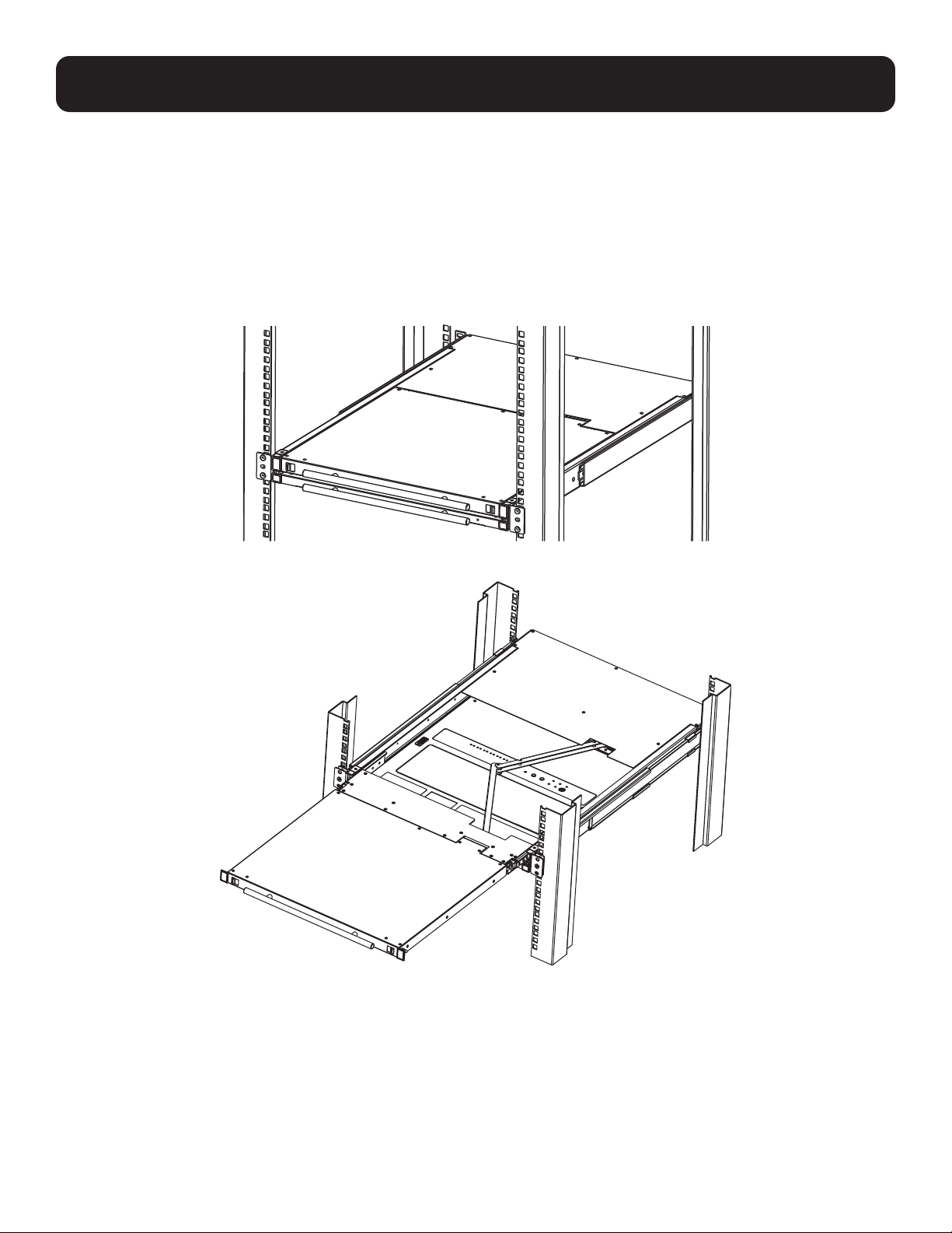
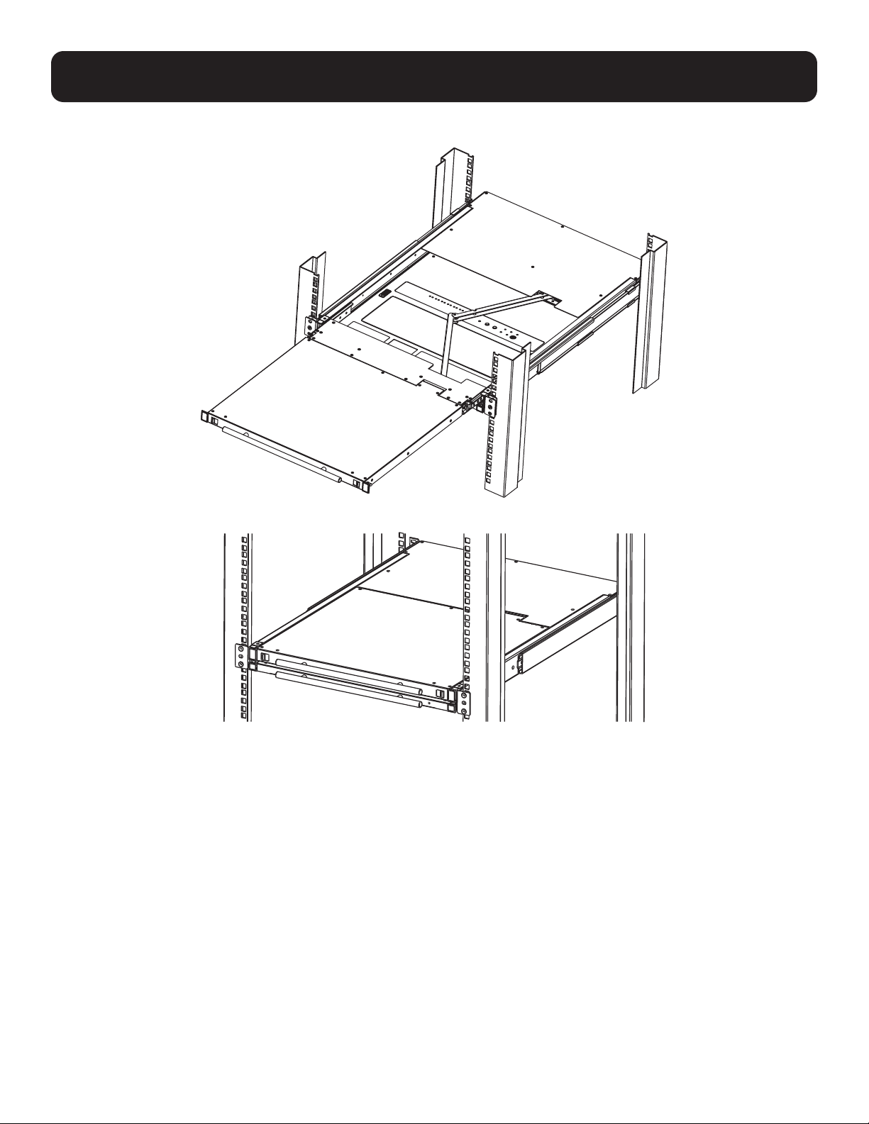
7.1 Standard Rack Mounting
The standard rack mounting brackets that come attached to the console KVM switch allow the device to be installed in a
standard 1U rack by a single individual.
1. Slide out the rear mounting brackets from the console and mount both brackets (separate from the console) to the inside
rear of a standard 1U rack system using user-supplied screws.
2. Gently slide the console into the two rear-mounted brackets in the rack and secure the console in place with user-supplied
screws.
7.2 2-Post Rack Mounting
The Console KVM Switch can also be mounted in a 2-post rack installation using the optional 2-Post Rack Mount Kit (Tripp Lite
model #: B019-000). The mounting hardware allows the console to be opened with the drawer in any position. Heavy-duty
14-gauge steel provides stability and prevents the console frame from twisting. See the B019-000 instructional manual for
detailed mounting instructions.
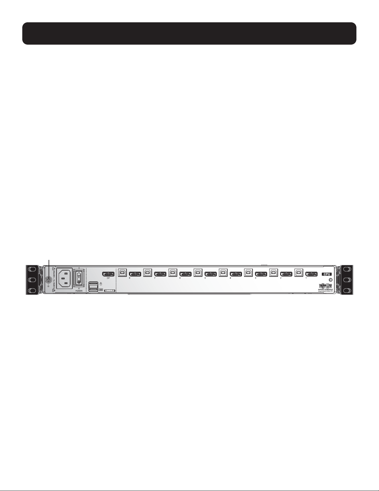
7.3 Grounding
To prevent damage to the installation, it is important that all devices are properly grounded. Use the included grounding wire
to ground the KVM switch by connecting one end of the wire to the grounding terminal on the device and the other end to a
suitably grounded object.
Grounding terminal
12
7. Installation
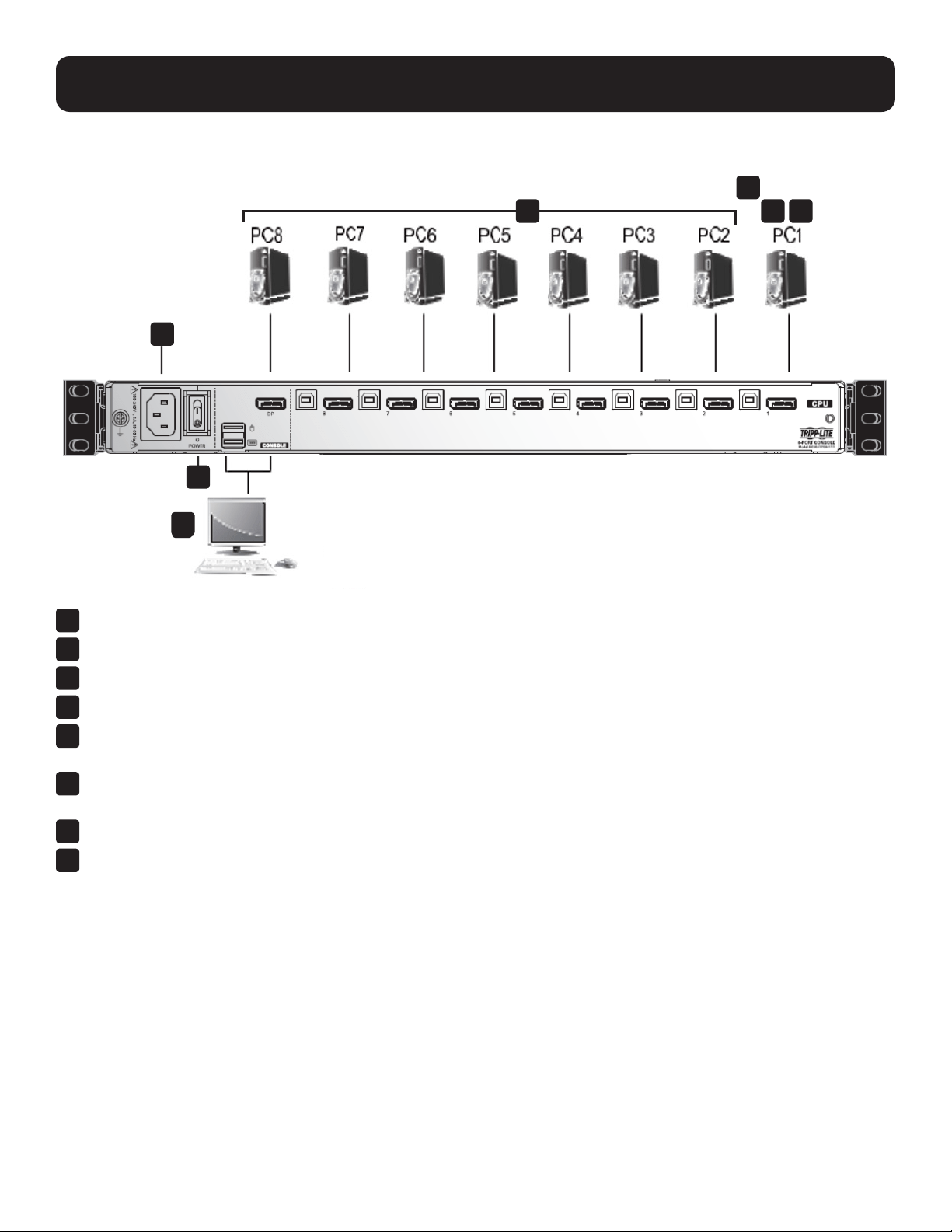
7.4 KVM Switch Installation
To set up the console KVM switch, refer to the following steps and installation diagram.
1
Power off all computers that will connect to the KVM switch.
2
Connect a USB cable from a USB CPU port on the KVM to the USB port on a computer.
3
Connect the DisplayPort CPU port on the KVM to the DisplayPort on a computer.
4
Repeat steps 2 and 3 for each additional computer you are connecting to the KVM.
5
(Optional) Add an external console to the KVM by connecting an DisplayPort monitor and USB keyboard and mouse to
the console ports on the back of the device.
6
Plug the included power cord into a Tripp Lite Surge Protector, Power Distribution Device (PDU), Uninterruptible Power
Supply (UPS) or AC wall outlet.
7
Power on the connected computers.
8
Power on the KVM device.
4
5
8
7
6
2 3
13
7. Installation
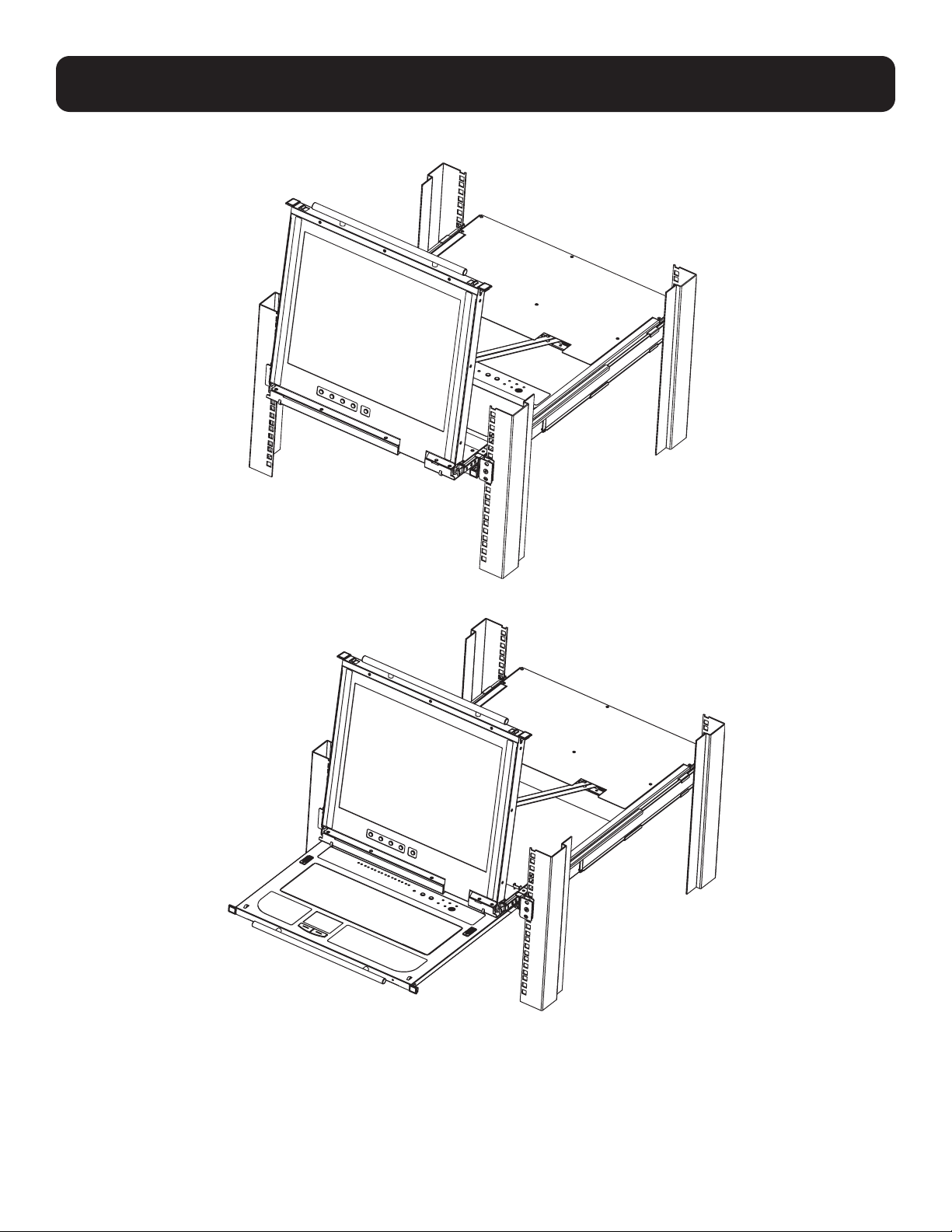
7.5 Opening / Closing the Console
The console consists of two modules: an LCD module located under the top cover and a keyboard / touchpad module below
the LCD module. The modules can slide together or independently of one another. This allows the LCD to be available for
viewing while the keyboard / touchpad module is not in use.
7.5.1 Opening Separately
1. Release the console by sliding the front panel toward the center. Then engage the catches and pull the top panel 1-2
inches toward you. Once the console has been released, release the catches.
2. Pull the top panel all the way out until it clicks into place.
14
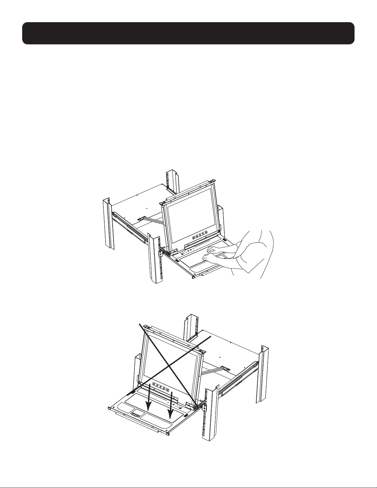
7. Installation
3. Rotate the top panel all the way back to expose the LCD screen.
4. Reach underneath and pull out the keyboard module until it clicks into place.
15
7. Installation
7.5.2 Opening Together
Refer to the diagrams in the Opening Separately section as you do the following:
1. Engage the release catches and pull the top and bottom panels out until the keyboard module clicks into place. Once the
console has been released, release the catches.
2. Pull the top panel out until it clicks into place.
3. Rotate the top panel all the way back to expose the LCD screen.
7.5.3 Opening Precautions
The maximum load bearing capacity of the keyboard module is 65 lb. Failure to heed the instructions below can result in
damage to the keyboard module.
CORRECT
Rest your hands and arms lightly on the keyboard module as you work.
INCORRECT!
• DO NOT apply body weight on the keyboard module.
• DO NOT place heavy objects on the keyboard module.
16
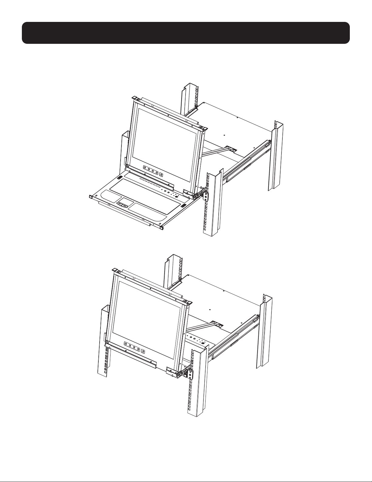
7. Installation
7.5.4 Closing the Console
1. Engage the release catches located on either side of the keyboard to release the keyboard module, then slide in the
module slightly.
2. Release the catches. Using the front handle, push the keyboard module all the way in.
17
7. Installation
3. Rotate the LCD module all the way down, then engage the rear catches to release the LCD module.
4. Using the front handle, push the module all the way in.
18
8. Basic Operation
8.1 LCD OSD Configurations
8.1.1 LCD Buttons
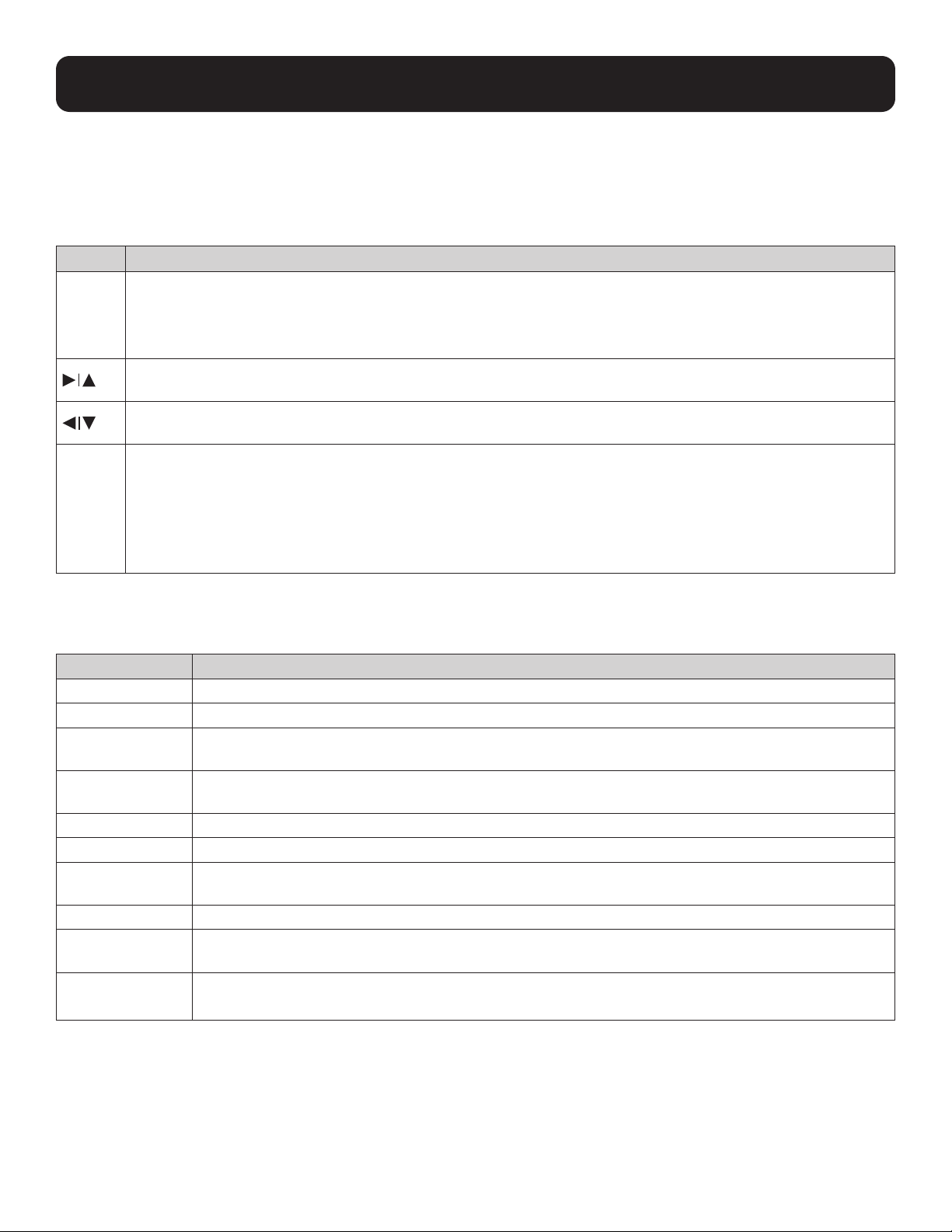
The LCD OSD configures the LCD. Four buttons are used to perform the configuration, as described in the table below:
Button Function
MENU • When the LCD OSD Menu function has not been entered, pressing this button initiates the Menu function and
the Main Menu.
• When the LCD OSD Menu function has been entered and has reached a setting choice with the navigation
buttons, pressing this button initiates the adjustment screen.
When navigating through the menus, this button moves the page right or up. When making an adjustment,
it increases the value.
When navigating through the menus, this button moves the page left or down. When making an adjustment,
it decreases the value.
EXIT • When the LCD OSD Menu function has not been entered, pressing this button performs an auto adjustment.
An auto adjustment automatically configures all the settings for the LCD to what the OSD considers their
optimum values to be.
• When you have entered the LCD OSD Menu function, pressing this button exits the current menu and returns
you to the previous menu. Use it to leave an adjustment menu when you are satisfied with the adjustments.
• When at the Main Menu, pressing this button exits the LCD OSD.
8.1.2 Adjustment Settings
LED OSD adjustment settings are described in the table below:
Setting Explanation
Brightness Adjusts the background black level of the screen image.
Contrast Adjusts the foreground white level of the screen image.
Phase If pixel jitter or horizontal line noise is visible on the display, the LCD may have the wrong phase setting.
Adjust the phase setting to eliminate these problems.
Clock If vertical banding is visible on the display, the LCD may have the wrong clock setting. Adjust the clock
setting to eliminate vertical banding.
H-Position Positions the display area on the LCD panel horizontally (moves the display area left or right).
V-Position Positions the display area on the LCD panel vertically (moves the display area up or down).
Color Temperature Adjusts the color quality of the display, such as the warmth value and color balance. The Adjust Color
selection contains a submenu to fine tune RGB values.
Language Selects the OSD display menus’ language.
OSD Duration Sets the amount of time the OSD will display on the screen. If there is no input for the amount of time
chosen, the OSD display turns off.
Reset Resets the adjustments on all menus and submenus to factory default settings.
Note: The Language setting does not return to the factory default, but remains at the one it is currently set to.

19
8. Basic Operation
8.1.3 Hot Plugging
The B030-DP08-17D / B030-DP16-17D support hot plugging – components can be removed and added to the computer by
unplugging their cables from the ports without the need to shut down the KVM.
8.1.4 Hot Plugging KVM Ports
In order for the OSD menus to correspond to KVM port changes, you must manually reconfigure the OSD to reflect the new
port information. See the F3 SET and F4 ADM functions in section 9.1.3.3 OSD Functions for details.
Note: If the computer’s operating system does not support hot plugging, this function may not work properly.
8.1.5 Powering Off and Restarting
If it becomes necessary to power off the KVM switch, or if the switch loses power and needs to be restarted, wait 10 seconds
before powering it back on. The computers should not be affected by this, but should any of them should fail, simply restart
the affected computers.
8.1.6 USB Peripheral Devices
The USB 1.1 port on the keyboard module’s front panel can connect a USB peripheral device, such as a flash drive, CD-ROM
drive or printer. Any computer connected to the device can access the USB peripheral on a one-by-one basis. When switching
from one computer to another, the peripheral device automatically disconnects from the original computer and connects to the
newly selected computer.
Note: When connecting a flash drive or other type of external storage device, always eject the device prior to switching ports.
8.1.7 Port Selection
The B030-DP08-17D / B030-DP16-17D provide three port-selection methods to access the computers on the installation:
manual, OSD (on-screen display), and hotkeys. For manual port switching, use the Port LED/Port Pushbuttons located on the
keyboard module to switch KVM focus to any port on the installation.

20
9. KVM Operation
9.1 Local Console
9.1.1 Local Console OSD Login
The OSD incorporates a two-level (administrator/user) password system. Before the ODS main screen displays, a login screen
appears requiring a password. If this is the first time the OSD is used or if the password function has not been set, simply
press [Enter]. The OSD main screen displays in administrator mode. In this mode, you have administrator privileges, with
access to all administrator and user functions. You can set up operations (including password authorization) as you like. If the
password function has been set, you must provide an appropriate administrator/user password in order to access the OSD.
9.1.2 Local Console OSD Hotkey Sequence
Once logged into the KVM switch and a connected computer, use the local console OSD Hotkey sequence to re-open the OSD
Main Menu. The default hotkey sequence is [Scroll Lock, Scroll Lock], but other options include [Ctrl, Ctrl].
Note: When using the [Scroll Lock, Scroll Lock] OSD Hotkey sequence, hold down the [Fn] key, as the [Scroll Lock] key is part of the [Num
Lock] key.
21
9. KVM Operation
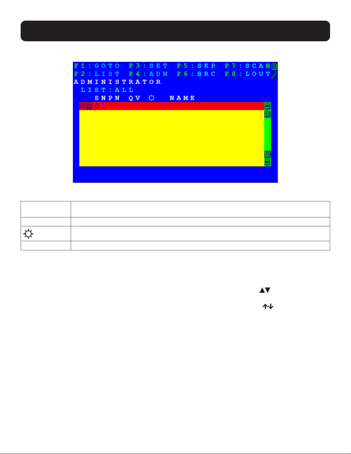
9.1.3 OSD Main Menu
9.1.3.1 OSD Main Menu Headings
PN This column lists the port ID numbers for all the KVM ports on the installation. The simplest method to
access a particular computer is move the highlight bar to it, then press Enter.
QV If a port has been selected for quick-view scanning, an arrowhead displays in this column.
The computers that are powered on and are online have a sun symbol in this column
NAME If a port has been given a name, its name appears in this column.
9.1.3.2 OSD Navigation
• To dismiss the menu, and deactivate OSD, click the X at the upper right corner of the OSD window or press [Esc].
• To log out, click F8 at the top of the main screen, or press [F8].
• To move up or down through the list one line at a time, click the up and down triangle symbols ( ) or use the up and
down arrow keys. If there are more list entries than what can appear on the main screen, the screen will scroll.
• To move up or down through the list one screen at a time, click the up and down arrow symbols ( ), or use the [Pg Up]
and [Pg Dn] keys. If there are more list entries than what can appear on the main screen, the screen will scroll.
• To activate a port, double-click it, or move the highlight bar to it and press [Enter].
• After executing any action, you automatically go back to the menu one level above.
9.1.3.3 OSD Functions
OSD functions are used to configure and control the OSD. For example, you can rapidly switch to any port, scan selected
ports, limit the list you wish to view, designate a port as a quick-view port, create or edit a port name, or make OSD setting
adjustments.
To access an OSD function:
1. Click a function key field at the top of the main screen or press a function key on the keyboard.
2. In the submenus that appear, either double-click on your selection or move the highlight bar to its location, then press
[Enter].
3. Press [Esc] to return to the previous menu level.

22
9. KVM Operation
F1: GOTO
Click the F1 field or press [F1] to activate the GOTO function. GOTO allows you to switch directly to a port either by keying in
the port’s name, or its port ID.
• To use the name method, key in 1; key in the port’s Name; then press [Enter].
• To use the port ID method, key in 2; key in the Port ID; then press [Enter].
Note: To return to the OSD main screen without making a selection, press [Esc].You can key in a partial name or port ID. In that case, the
screen will show all the computers that the user has View rights to (see Set Accessible Ports for details), that match the name or port ID
pattern, regardless of the current list settings (see F2 List for details).
F2: LIST
This function lets you broaden or narrow the scope of which ports the OSD displays on the main screen. The submenu
selections and their definitions are shown in the table below.
Selection Definition
ALL Lists all of the ports on the installation that have been set by the administrator as accessible for the
current logged in user.
QUICK VIEW Lists only the ports selected as quick-view ports (see SET QUICK VIEW PORTS).
POWERED ON Lists only the ports with their attached computers powered on.
QUICK VIEW +
POWERED ON
Lists only the ports selected as quick-view ports (see SET QUICK VIEW PORTS) and have their attached
computers powered on.
Move the highlight bar to your selection, then press [Enter]. An icon appears before the selection to indicate that it is currently
selected.
F3: SET
This function allows the administrator and each user to set up their own working environment. A separate profile for each is
stored by the OSD and is activated according to the username that was provided during login.
To change a setting:
1. Double-click it; or move the highlight bar to it, then press [Enter].
2. After you select an item, a submenu with further choices appears. To make a selection, either double-click it; or move the
highlight bar to it, then press [Enter]. An icon appears before the selection to indicate which one it is. The settings are
explained in the following table:
Setting Function
OSD HOTKEY Selects which hotkey activates the OSD function:
[Scroll Lock] [Scroll Lock] or [Ctrl] [Ctrl].
Since the [Ctrl] key combination may conflict with programs running on the computers, the default is
the [Scroll Lock] combination.
PORT ID DISPLAY
POSITION
Allows each user to customize the position where the port ID appears on the screen. The default is the
upper left corner, but users can choose to have it appear anywhere on the screen. Use the mouse or
the arrow keys plus [Pg Up], [Pg Dn], [Home], [End] and [5] (on the numeric keypad with Num Lock
off), to position the port ID display, then double-click or press [Enter] to lock the position and return to
the Set submenu.
PORT ID DISPLAY
DURATION
Determines how long a port ID displays on the monitor after a port change has taken place. The choices
are 3 Seconds and Always Off (default).
PORT ID DISPLAY
MODE
Selects how the port ID is displayed: the port number plus the port name (PORT NUMBER + PORT
NAME) (default); the port number alone (PORT NUMBER) or the port name alone (PORT NAME).
SCAN DURATION Determines how long the focus dwells on each port as it cycles through the selected ports in Auto Scan
mode (see F7: SCAN). Key in a value from 1–255 seconds, then press [Enter]. Default is 5 seconds; a
setting of 0 disables the SCAN function.

23
9. KVM Operation
Setting Function
SCAN-SKIP MODE Selects which computers will be accessed under skip mode (see F5: SKP), and Auto Scan mode (see
F7: SCAN). Choices are:
ALL - All the ports which have been set accessible (see SET ACCESSIBLE PORTS).
QUICK VIEW - Only those ports which have been set accessible and have been selected as quick-view
ports (see SET QUICK VIEW PORTS).
POWERED ON - Only those ports which have been set accessible and are powered on.
QUICK VIEW + POWERED ON - Only those ports which have been set accessible and have been
selected as quick-view ports and are powered on. The default is ALL.
Note: The quick-view choices only show up on the administrator’s screen, since only he/she has Quick View setting
rights (see SET QUICK VIEW PORTS for details).
SCREEN BLANKER If there is no input from the console for the amount of time set by this function, the screen is blanked.
Key in a value from 1-30 minutes, then press [Enter]. The default setting of 0 disables this function.
HOTKEY
COMMAND MODE
Enables/disables the hotkey command function in case a conflict with programs running on the
computers occurs.
HOTKEY Sets the keyboard shortcut for invoking Hotkey Mode:
Choices are: NUM LOCK + - (minus) (default) and CTRL + F12.
OSD LANGUAGE Sets the language used in the OSD. Choices are: English (default), German, Japanese, Simplified
Chinese and Traditional Chinese.
F4: ADM
F4 is an administrator-only function. It allows the administrator to configure and control the overall operation of the OSD. To
change a setting, double-click it or use the up and down arrow keys to move the highlight bar to it, then press [Enter].
After you select an item, a submenu with further choices appears. Double-click an item or move the highlight bar to it, then
press [Enter]. An icon appears before the selected item to indicate which one it is. The settings are described in the following
table:
Setting Function
SET USER LOGIN This function is used to set usernames and passwords for the administrator and users:
1. Usernames and passwords for one administrator and four users can be set.
2. After you select the administrator field or one of the user fields, a screen that allows you to key in
the username and password appears. Usernames and passwords can be from 1 to 16 characters
long and can consist of any combination of letters and numbers (A–Z, 0–9) and some additional
keys (* ( ) + : - , ? . / space).
3. For each individual, key in the username and password, confirm the password, then press [Enter].
4. To modify or delete a previous username and/or password, use the backspace key to erase individual
letters or numbers. Press [Enter] when done.
Note: Usernames and passwords are not case sensitive. Usernames are displayed in capital letters in the OSD.
SET ACCESSIBLE
PORTS
This function enables the administrator to define user access to the computers on the installation on a
port-by-port basis. For each user, select the target port, then press the [Spacebar] to cycle through the
choices: F (full access), V (view only), or blank. Repeat until all access rights have been set, and then
press [Enter]. The default is F for all users on all ports.
Notes:
• A blank setting means no access rights are granted. The port will not show up in the user’s LIST on the main
screen.
• The administrator always has full access to all ports.

24
9. KVM Operation
Setting Function
SET LOGOUT
TIMEOUT
If there is no input from the console for the amount of time set with this function, the user is
automatically logged out. A login is necessary before the console can be used again. This enables other
users to gain access to the computers when the original user is no longer accessing them, but has
forgotten to log out. To set the timeout value, key in a number from 1-180 minutes, then press [Enter].
The default setting of 0 disables this function.
Note: This feature does not function if Set Login Mode is disabled. See section x,x SET LOGIN MODE.
EDIT PORT NAMES To help identify which computer is attached to a particular port, every port can be given a name. This
function allows the administrator to create, modify, or delete port names.
To edit a port name:
1. Click the port or use the navigation keys to move the highlight bar to it, then press [Enter].
2. Key in the new port name or modify/delete the existing name. The maximum number of characters
allowed for the port name is 12. Legal characters include:
• All alpha characters: A–Z
• All numeric characters: 0–9
• ( ) + : - , ? . / and Space
Port names are not case-sensitive; the OSD displays the port name in all capitals no matter how they
were keyed in.
3. When you have finished editing, press [Enter] to have the change take effect. To abort the change,
press [Esc].
RESTORE DEFAULT
VALUES
This function is used to undo all changes and return the setup to the original factory default settings
(see OSD Factory Default Settings) except for the port name list, username and password information,
which are saved.
CLEAR THE NAME
LIST
This function clears the port name list.
ACTIVATE BEEPER Choices are Y (on), or N (off). When activated, the beeper sounds whenever a port is changed, when
activating the Auto Scan function (see F7: SCAN) or an invalid entry is made on an OSD menu. The
default is Y.
SET QUICK VIEW
PORTS
This function lets the administrator select which ports to include as quick-view ports.
• To select/deselect a port as a quick-view port, double-click the port or use the navigation keys to
move the highlight bar to it, then press [Spacebar].
• When a port has been selected as a quick-view port, an icon displays in the QV column of the LIST on
the main screen. When a port is deselected, the icon disappears.
• If one of the quick-view options is chosen for the LIST view (see F2 LIST), only a port that has been
selected here will display on the list.
• If one of the quick-view options is chosen for auto-scanning (see SCAN–SKIP MODE), only a port that
has been selected here will be auto-scanned.
The default has no ports selected for quick view.
SET OPERATING
SYSTEM
This function allows the administrator to define the operating system for the computer connected to
each KVM port. The default is WIN (PC compatible). To set the port operating system:
1. From the list, select the port for which you wish to set the computer’s operating system.
2. Set the operating system by pressing [Spacebar] to cycle through WIN, MAC, SUN or OTHER.
3. Press [Esc] to exit. The operating system you selected is assigned to the KVM port.

25
9. KVM Operation
Setting Function
FIRMWARE
UPGRADE
In order to upgrade the Console KVM Switch’s firmware, you must first enable Firmware Upgrade mode
with this setting. When you bring up this menu, the current firmware version levels are displayed. Select
Y to enable Firmware Upgrade mode, or N to leave this menu without enabling it.
SET KEYBOARD
LANGUAGE
Sets the language for the computer keyboard attached to the KVM port. To select a keyboard language,
double-click it or use the navigation keys to move the highlight bar to it, then press [Enter]. Choices are:
AUTO (default), ENGLISH (UK), ENGLISH (US), FRENCH, GERMAN (GER.), GERMAN (SWISS), GREEK,
HUNGARIAN, ITALIAN, JAPANESE, KOREAN, RUSSIAN, SPANISH, SWEDISH and TRADITIONAL CHINESE.
SET LOGIN MODE This function enables the administrator to request users to login or not. When the login dialog box
is disabled, the system disables the login/logout function. If the system is restarted, the login/logout
function remains disabled.
F5: SKP
Clicking the F5 field or pressing [F5] invokes Skip (SKP) mode. This function enables you to easily skip backward or forward –
switching the console focus from the currently active computer port to the previous or next available port.
• The selection of computers to be available for skip mode switching is made with the Scan–Skip mode setting under the F3:
SET function.
• When you are in skip mode:
o Press [ ] to switch to the previous computer in the list.
o Press [ ] to switch to the next computer in the list.
Note: When you skip, you only skip to the previous or next available computer that is in the Scan–Skip mode selection.
• If a port has been selected for Scan-Skip mode, when the focus switches to that port a left/right triangle symbol appears before its port
ID display.
• While skip mode is in effect, the console will not function normally. You must exit skip mode in order to regain control of the console.
• To exit skip mode, press [Spacebar] or [Esc].
F6: BRC
F6 is an administrator-only function. Clicking the F6 field, or pressing [F6], invokes Broadcast (BRC) mode. When this function
is in effect, commands sent from the console are broadcast to all available computers on the installation.
This function is particularly useful for operations that need to be performed on multiple computers, such as performing a
system wide shutdown, installing or upgrading software, etc.
• While BRC mode is in effect, a speaker symbol appears before the port ID display of the port that currently has the console
focus.
• While BRC mode is in effect, the mouse will not function normally. Exit BRC mode in order to regain control of the mouse.
• To exit BRC mode, invoke the OSD (with the OSD hotkey), then click the F6 field, or press [F6], to turn BRC mode off.

26
9. KVM Operation
F7: SCAN
Clicking the F7 field or pressing [F7] invokes Auto Scan mode. This function allows you to switch automatically among the
available computers at regular intervals so you can monitor their activity without manual switching.
• The selection of computers to be included for auto-scanning is made with the Scan-Skip mode setting under the F3: SET
function.
• The amount of time each port displays for is set with the Scan Duration setting under the F3: SET function. To stop at a
particular location, press the [Spacebar] to stop scanning.
• If the scanning stops on an empty port or one where the computer is attached but powered off, the monitor screen will be
blank, and the mouse and keyboard will have no effect. After the Scan Duration time is up, the scan function will move on to
the next port.
• As each computer is accessed, an S appears in front of the port ID display to indicate that it is being accessed under Auto
Scan mode.
• While Auto Scan mode is in effect, the console will not function normally. You must exit Auto Scan mode in order to regain
control of the console.
• While you are in Auto Scan mode, you can pause the scanning in order to keep the focus on a particular computer either by
pressing P, or with a left-click of the mouse. See Invoking Auto Scan for details.
• To exit Auto Scan mode, press the [Spacebar] or [Esc].
F8: LOUT
Clicking the F8 field, or pressing [F8] logs you out of OSD control of the computers and blanks the console screen. This is
different from simply pressing [Esc] when you are at the main screen to deactivate the OSD. With this function, you must log
in again to regain access to the OSD, whereas with [Esc], all you have to do to reenter the OSD is tap the OSD hotkey.
Notes:
1. When you reenter the OSD after logging out, the screen stays blank except for the OSD main screen. You must input your username and
password before you can continue.
2. If you reenter the OSD after logging out, and immediately use [Esc] to deactivate the OSD without having selected a port from the OSD
menu, a null port message displays on the screen. The OSD hotkey will bring up the main OSD screen.

27
10. Keyboard Port Operation
10.1 Hotkey Port Control
Hotkey port control allows you to provide KVM focus to a particular computer directly from the keyboard. The Console KVM
Switch provides the following hotkey port control features:
• Selecting the Active Port
• Auto Scan Mode Switching
• Skip Mode Switching
• Computer Keyboard/Mouse Reset
The following settings can also be controlled in Hotkey mode:
• Setting the Beeper
• Setting the Quick Hotkey
• Setting the OSD Hotkey
• Setting the Port Operating System
• Restoring the OSD Default Values
10.1.1 Invoke Hotkey Mode
All hotkey operations begin by invoking Hotkey mode. (Ensure the Hotkey Command Mode function is enabled and that you
key in the appropriate hotkey.) There are two possible keystroke sequences used to invoke Hotkey mode, though only one can
be operational at any given time: num lock and minus keys.
1. Hold down the num lock key;
2. Press and release the minus key;
3. Release the num lock key: [Num Lock] + [-]
Note: Ensure the Hotkey Command Mode function is enabled and key in the appropriate hotkey.
When Hotkey mode is active:
• A command line appears on the monitor screen. The command line prompt is the word Hotkey: in white text on a blue
background and displays the subsequent hotkey information that you key in.
• Ordinary keyboard and mouse functions are suspended – only hotkey compliant keystrokes (described in the sections that
follow), can be input.
Pressing [Esc] exits Hotkey mode.
10.1.2 Select the Active Port
Each KVM port is assigned a port ID (see Port ID Numbering). You can directly access any computer on the installation with
a hotkey combination that specifies the port ID of the KVM port a computer is connected to. To access a computer using
hotkeys:
1. Invoke hotkey mode with the [Num Lock] + [-] or [Ctrl] + [F12] combination.
2. Key in the port ID. The port ID numbers display on the command line as you key them in. If you make a mistake, use
[Backspace] to erase the wrong number.
3. Press [Enter]. After pressing [Enter], the KVM focus switches to the designated computer and hotkey mode is exited
automatically.
Note: In Hotkey mode, the KVM focus will not switch to a port if an invalid switch or port number is entered. The hotkey command line will
continue to display on the screen until you enter a valid switch and port number combination or exit Hotkey mode.

28
10. Keyboard Port Operation
10.1.3 Auto Scan Mode
Auto Scan automatically switches, at regular intervals, among all the KVM ports that have been set as accessible under Scan-
Skip Mode, so that their activity can be monitored automatically. See SCAN-SKIP MODE for more information.
Invoke Auto Scan
To start Auto Scan, key in the following hotkey combination:
1. Invoke hotkey mode with the [Num Lock] + [-] or the [Ctrl] + [F12] combination.
2. Press [A]. Once you press [A], then [Enter], the KVM switch automatically exits hotkey mode and enter Auto Scan mode.
• While in Auto Scan mode, you can pause the scanning in order to keep the focus on a particular computer either by
pressing P or with a left click of the mouse. During the time auto-scanning is paused, the command line displays Auto
Scan: Paused.
• Pausing when you want to keep the focus on a particular computer is more convenient than exiting Auto Scan mode,
because when you resume scanning, you start from where you left off. If, on the other hand, you exited and restarted,
scanning would start over from the very first computer on the installation.
• To resume Auto Scan, press any key or left-click. Scanning continues from where it left off.
• While Auto Scan mode is in effect, ordinary keyboard and mouse functions are suspended – only Auto Scan mode-
compliant keystrokes and mouse clicks can be input. Exit Auto Scan mode in order to regain normal control of the
console.
3. To exit Auto Scan mode press [Esc] or [Spacebar]. Auto-scanning stops when you exit Auto Scan mode.
10.1.4 Skip Mode
This feature allows you to switch between computers in order to monitor them manually. You can dwell on a particular port for
as long as you like, as opposed to auto-scanning, which automatically switches after a fixed interval. To invoke Skip mode, key
in the following hotkey combination:
1. Invoke hotkey mode with the [Num Lock] + [-] or the [Ctrl] + [F12] combination.
• Key in [Arrow], where [Arrow] refers to one of the arrow keys. After an arrow key is pressed, the KVM switch automatically
exits Hotkey mode and enters Skip mode where you can switch ports as follows:
Skips to first accessible port. (See Scan/Skip Mode for details)
Skips to the next accessible port.
• Once you are in Skip mode, you can keep on skipping by pressing the arrow keys. You don’t have to use the [Num Lock]
+ [-] combination again.
• While Skip mode is in effect, ordinary keyboard and mouse functions are suspended – only Skip mode-compliant
keystrokes can be input. Exit Skip mode in order to regain normal control of the console.
2. To exit Skip mode, press [Esc] or [Spacebar].
10.1.5 Computer Keyboard/Mouse Reset
If the keyboard or mouse ceases to function on the computer connected to the currently selected port, you can perform a
keyboard/mouse reset on the computer. This function is essentially the same as unplugging and replugging the keyboard and
mouse on the target computer. To perform a computer keyboard/mouse reset, key in the following hotkey combination:
1. Invoke hotkey mode with the [Num Lock] + [-] or the [Ctrl] + [F12] combination.
2. Press [F5].
After pressing [F5], the KVM switch automatically exits Hotkey mode and regain keyboard and mouse control on the computer
connected to the KVM port. If you fail to regain keyboard/mouse control on the computer after pressing [F5], perform a
console keyboard and mouse reset.

29
10. Keyboard Port Operation
10.1.6 Hotkey Beeper Control
The beeper (see ACTIVATE BEEPER) can be toggled on and off with a hotkey. To toggle the beeper, key in the following hotkey
combination:
1. Invoke hotkey mode with the [Num Lock] + [-] or [Ctrl] + [F12] combination.
2. Press [B].
Pressing [B], toggles the beeper on or off. The command line displays Beeper On or Beeper Off for one second; then the
message disappears and the KVM switch automatically exits hotkey mode.
10.1.7 Quick Hotkey Control
The Quick Hotkey (see HOTKEY) can be toggled between [Num Lock] + [-], and [Ctrl] + [F12]. To toggle the Quick Hotkey, key
in the following combination:
1. Invoke hotkey mode with the [Num Lock] + [-] or [Ctrl] + [F12] combination.
2. Press [H].
Once [H] is pressed, the command line displays HOTKEY HAS BEEN CHANGED for one second; then the message disappears
and the KVM switch automatically exits Hotkey mode.
10.1.8 Port Operating System Control
A port’s operating system can be changed to match that of the computer attached to the port. To change a port’s operating
system, key in the following hotkey combination:
1. Invoke hotkey mode with the [Num Lock] + [-] or [Ctrl] + [F12] combination.
2. Key in [Function], where [Function] refers to one of the function keys in the following table:
Key Description
F1 Sets the Port OS to Windows
F2 Sets the Port OS to Mac
F3 Sets the Port OS to Sun
After pressing a function key, the KVM switch automatically exits Hotkey mode.
10.1.9 Set USB Speed
A hotkey can be used to set the USB speed of the selected KVM port as low/full speed, compliant with the port’s connected
computer.
1. Invoke hotkey mode with the [Num Lock] + [-] or [Ctrl] + [F12] combination.
2. Press [F11][L]/[F11][F].
3. Press [Enter].
• [L] Indicates the selected KVM port set as USB low speed.
• [F] Indicates the selected KVM port set as USB full speed.
To set all KVM ports to the speed of the selection, use hotkey commands [F11][L][A], [Enter] / [F11][F][A], [Enter].

30
10. Keyboard Port Operation
10.1.10 Restore Default Values
This administrator-only hotkey restores the Console KVM Switch’s default values. See RESTORE DEFAULT VALUES. To restore
the default values, key in the following hotkey combination:
1. Invoke hotkey mode with the [Num Lock] + [-] or [Ctrl] + [F12] combination.
2. Press [R].
3. Press [Enter].
Once [Enter] is pressed, the command line displays RESET TO DEFAULT SETTING for three seconds; then the message
disappears and the KVM switch automatically exits Hotkey mode.
10.2 Hotkey Summary Table
HSM Mode
[Num Lock] + [-]
or
[Ctrl] + [F12]
[PN] [Enter] Switches KVM, Audio and USB focus directly to the computer that
corresponds to that port ID. (PN = port number)
[A] [Enter] Starts Auto Scan. The KVM focus cycles from port to port at the default
5-second intervals.
[A] [n] [Enter] Starts Auto Scan at n-second intervals (n = 1–255 seconds).
[H] Toggles between the default ([Num Lock] [-]) and alternate ([Ctrl] [F12])
Hotkey Settings Mode invocation keys.
[T] Toggles the OSD Hotkey between [Ctrl] [Ctrl] and [Scroll Lock] [Scroll Lock].
[F1] Set the port OS to Windows.
[F2] Set the port OS to Mac.
[F3] Set the port OS to Sun.
[F5] Performs a keyboard / mouse reset on the target computer.
[B] Enables / Disables the buzzer.
[R] [Enter] [R] [Enter] Resets hotkey settings to their default values. See RESTORE
DEFAULT VALUES for details
[←] Skips to the previous computer on the list, in Skip Mode.
[←] Skips to the next computer on the list in, Skip Mode.
[ESC] or [Spacebar] Exits Hotkey Settings Mode.
31
11. Keyboard Emulation
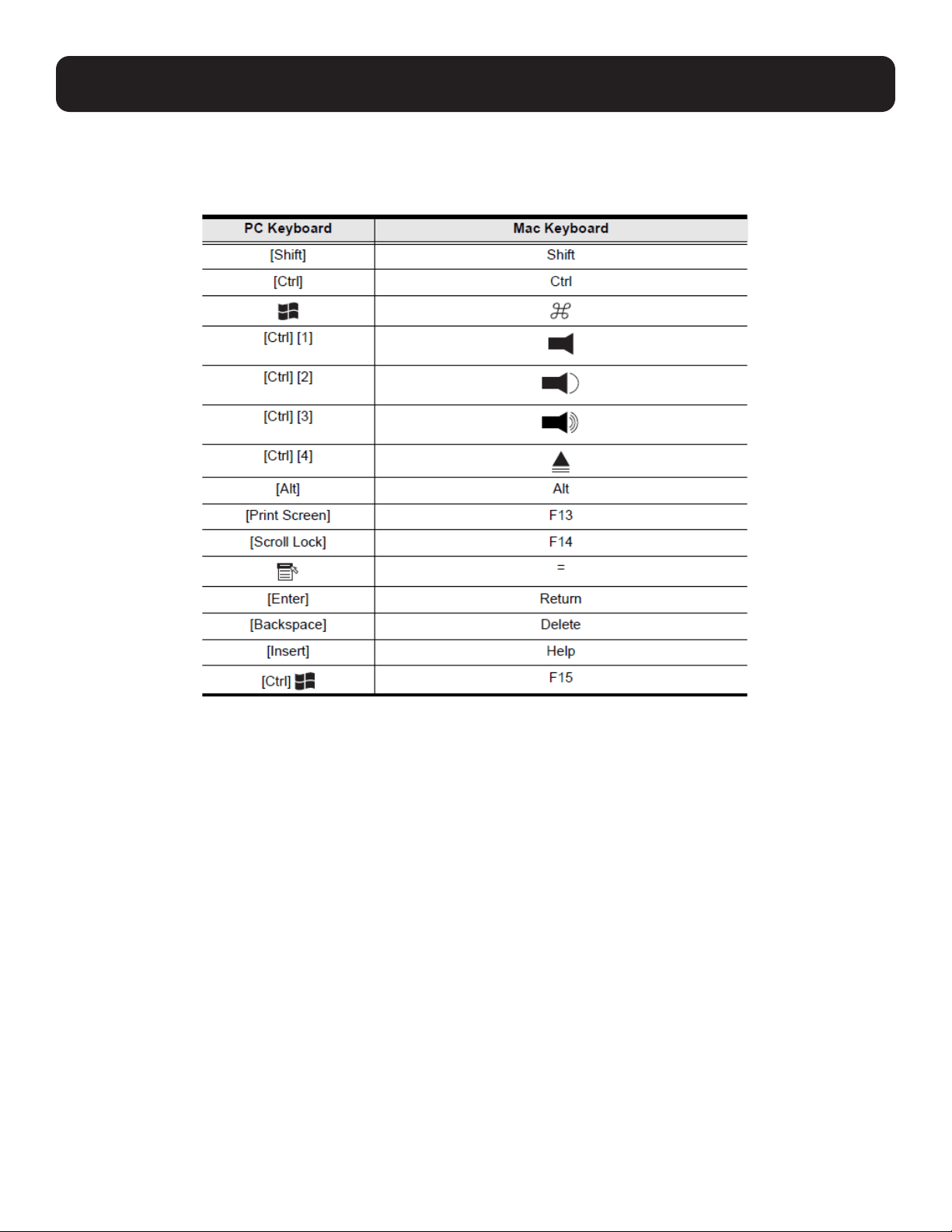
Mac Keyboard
The PC-compatible (101/104 key) keyboard can emulate the functions of the Mac keyboard. The emulation mappings are
listed in the table below.
Note: When using key combinations, press and release the first key (Ctrl), then press and release the activation key.
32
11. Keyboard Emulation
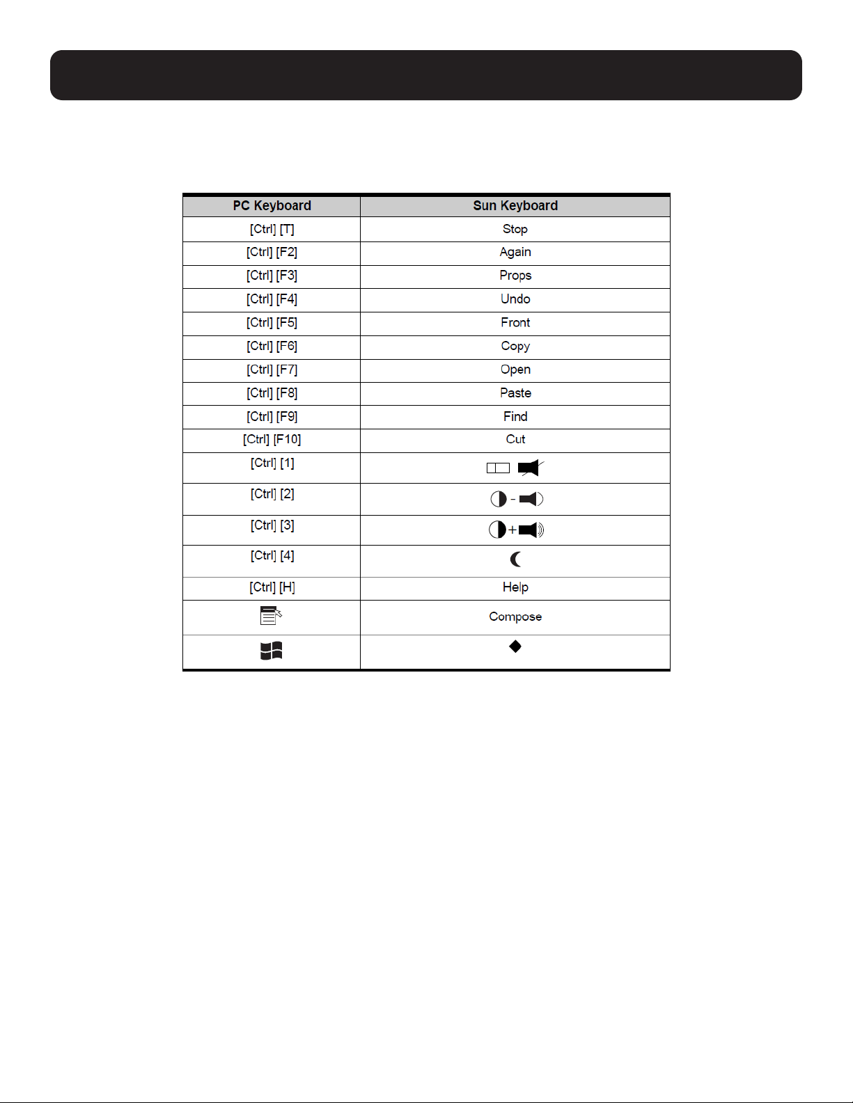
Sun Keyboard
The PC-compatible (101/104 key) keyboard can emulate the functions of the Sun keyboard when the control key [Ctrl] is used
in conjunction with other keys. The corresponding functions are shown in the table below.
Note: When using key combinations, press and release (Ctrl), then press and release the activation key.
33
12. Firmware Upgrade Utility
12.1 Introduction
The purpose of the Windows-based Firmware Upgrade Utility is to provide an automated process for upgrading all B030-DP08-
17D / B030-DP16-17D switches in an installation. The program comes as part of a firmware upgrade package specific for
each device.
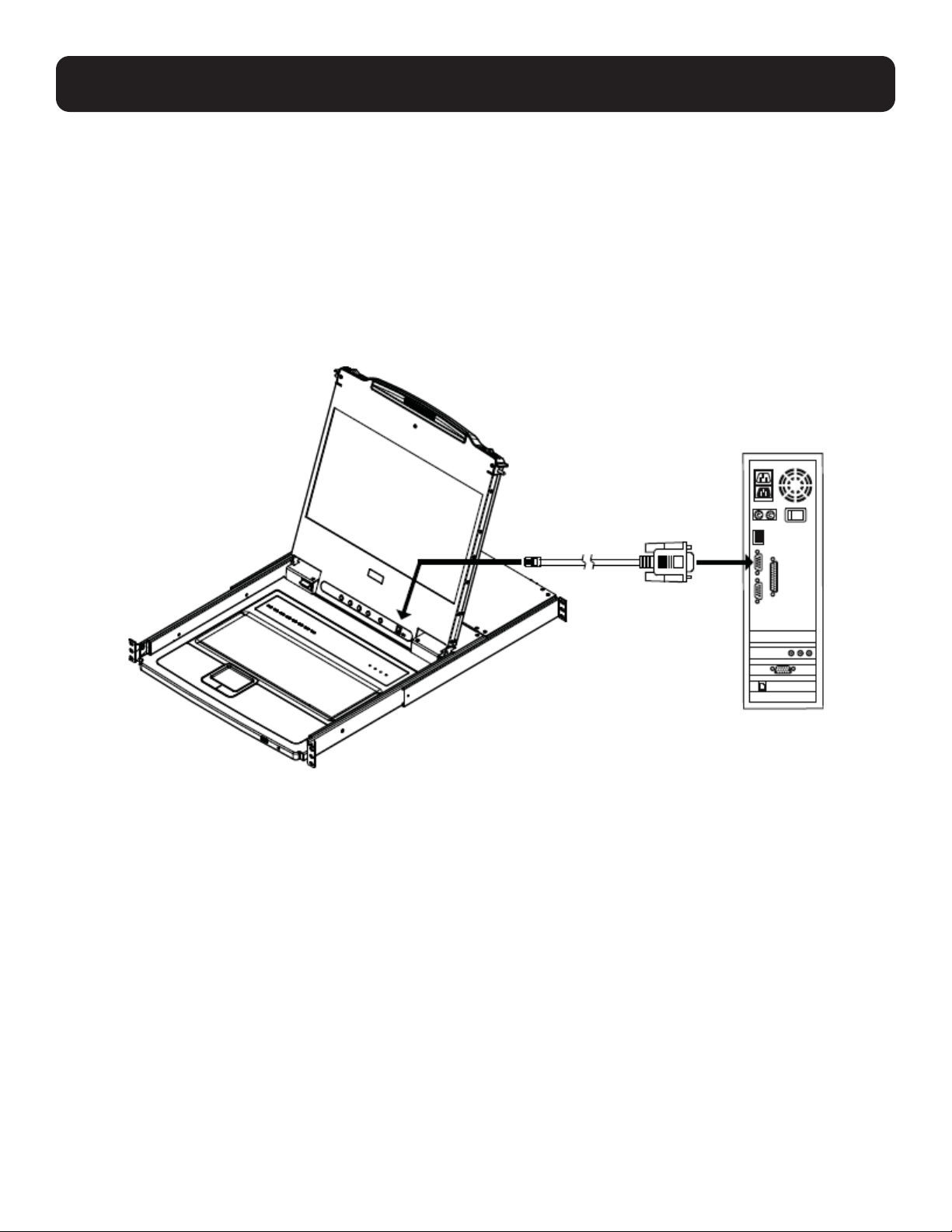
12.2 Preparation
To prepare for the firmware upgrade, do the following:
1. Use the firmware upgrade cable provided with the unit to connect a COM port on your computer to the firmware upgrade
port on the switch.
2. Shut down all the computers on the KVM installation.
3. From your KVM switch console, log into the OSD as the administrator and select F4 ADM function .
4. Scroll down to FIRMWARE UPGRADE. Press [Enter], and then press [Y] to invoke Firmware Upgrade Mode.
34
12. Firmware Upgrade Utility
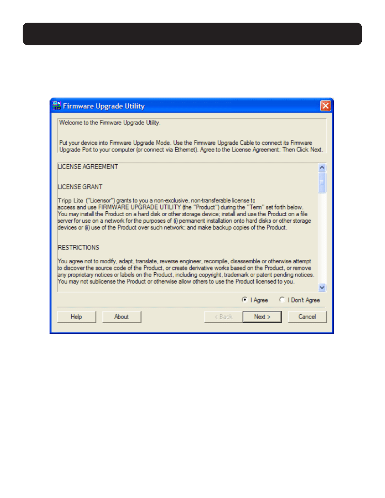
12.3 Starting the Upgrade
To upgrade the firmware:
1. Run the downloaded firmware upgrade package file either by double-clicking the file icon or by opening a command line
and entering the full path to it. The firmware upgrade utility welcome screen appears:
Note: The screens shown in this section are for reference only. The wording and layout of the actual screens put up by the Firmware
Upgrade Utility may vary slightly from these examples.
2. Read and agree to the license agreement (enable the I Agree radio button).
35
12. Firmware Upgrade Utility
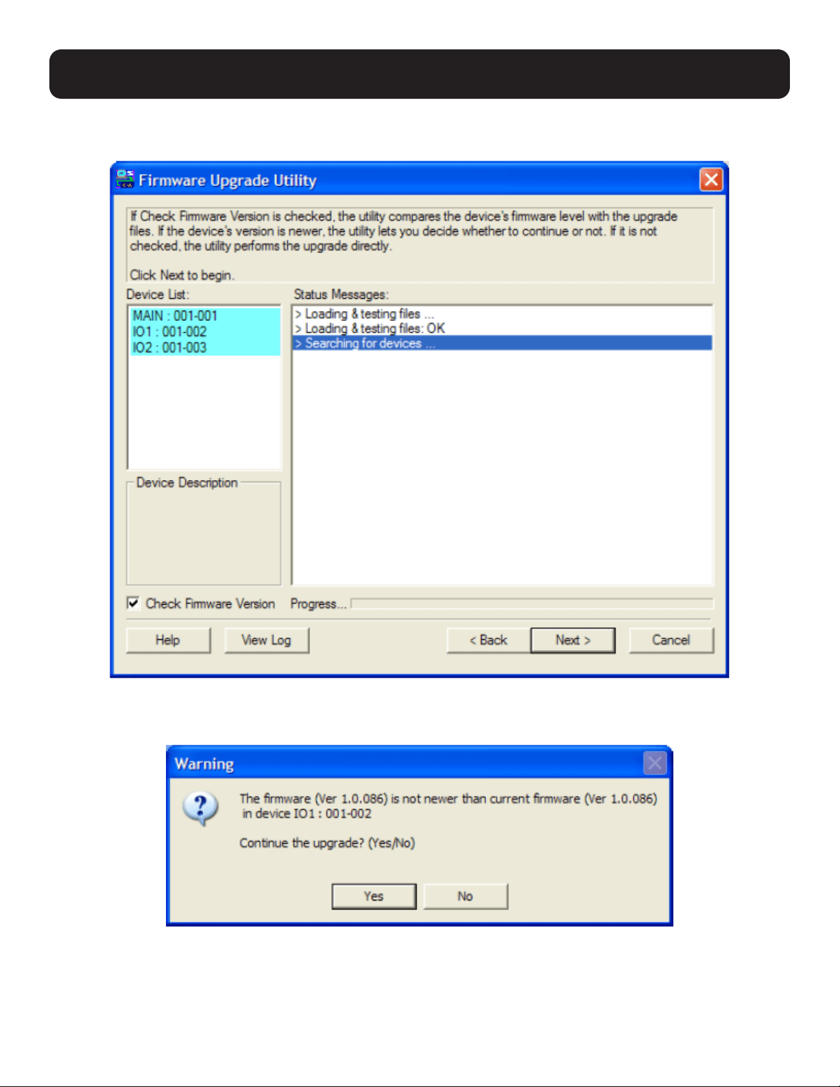
3. Click “Next” to continue. The firmware upgrade utility main screen appears. The devices capable of being upgraded are
listed in the Device List panel:
4. Click “Next” to perform the upgrade. If you enabled Check Firmware Version, the utility compares the device’s firmware
level with that of the upgrade files. If it finds that the device’s version is higher than the upgrade version, a dialog box
appears and gives you the option to continue or cancel.
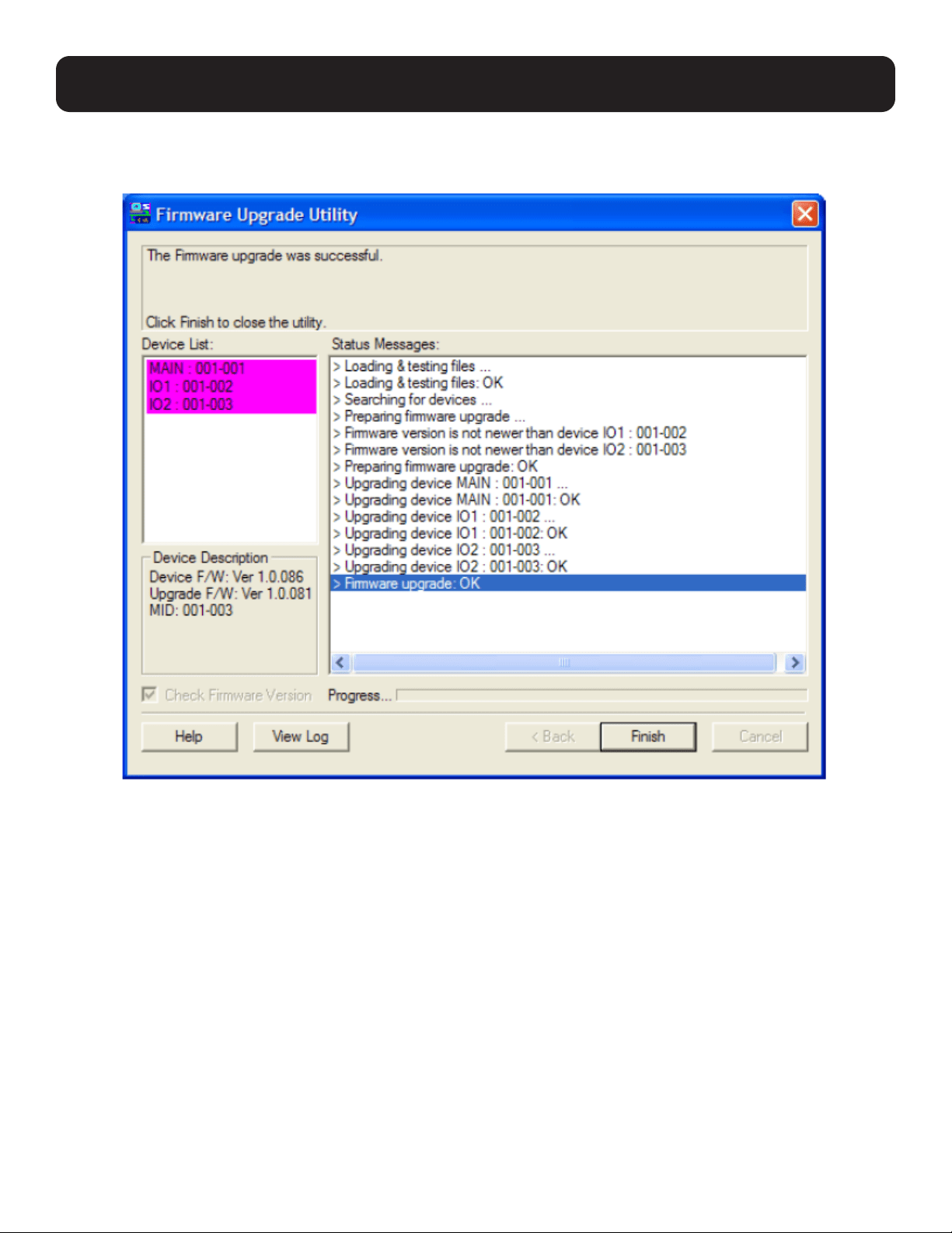
If you did not enable Check Firmware Version, the utility installs the upgrade files without checking if they are a higher level. As
the upgrade proceeds, status messages appear in the Status Messages panel, and the progress toward completion is shown
on the Progress bar.
36
12. Firmware Upgrade Utility
Upgrade Succeeded
After the upgrade has completed, a screen appears to inform you that the procedure was successful.
Click “Finish” to close the firmware upgrade utility.
Upgrade Failed
If the Upgrade Succeeded screen does not appear, the upgrade failed to complete successfully. See the following section,
Firmware Upgrade Recovery, for how to proceed.

37
12. Firmware Upgrade Utility
12.4 Firmware Upgrade Recovery
There are three conditions that call for firmware upgrade recovery:
• When a firmware upgrade is aborted manually.
• When the mainboard firmware upgrade fails.
• When the I/O firmware upgrade fails.
To perform a firmware upgrade recovery, do the following:
1. Power off the switch.
2. Connect the firmware upgrade cable to the firmware upgrade port.
3. Slide the firmware upgrade recovery switch to the Recover position.
4. Power the switch on and repeat the upgrade procedure.
5. After the switch has been upgraded successfully, power it off and slide the firmware upgrade recovery switch back to the
Normal position.
6. If the switch is part of a cascaded installation, plug it back into the installation.
7. Power the switch on.

38
13. Specifications and Default Settings
13.1 Specifications
Model B030-DP08-17D B030-DP16-17D
NetDirector 8-Port 1U Rack-Mount Console
DisplayPort KVM Switch with 17 in. LCD,
Dual Rail
NetDirector 16-Port 1U Rack-Mount Console
DisplayPort KVM Switch with 17 in. LCD,
Dual Rail
Port Selection Methods Pushbutton, OSD, Hotkey Pushbutton, OSD, Hotkey
External Console Ports Displayport (Female), 2 x USB-A (Female) Displayport (Female), 2 x USB-A (Female)
Computer Ports 8 16
RJ11 Firmware Upgrade Port 1 1
Housing Metal, Dual-Rail Metal, Dual-Rail
Power LEDs 1 x Green 1 x Green
Online LEDs 8 x Orange 16 x Orange
Selected LEDs 8 x Green 16 x Green
Power Input Connector IEC-320-C14 IEC-320-C14
I/P Rating 100-240V, 50/60 Hz 1A 100-240V, 50/60 Hz 1A
On/Off Power Switch Yes Yes
Firmware Upgrade Switch 1 (Slide) 1 (Slide)
Additional USB Ports 1 (USB 1.1) 1 (USB 1.1)
Reset Button Yes Yes
Port Selection Pushbuttons 8 16
Keyboard/Mouse Emulation USB (PC, Mac, Sun) USB (PC, Mac, Sun)
Max Video Resolution
(Local and 2nd Console)
1920 x 1080 @ 60 Hz, DDC2B, HDCP 1.4 1920 x 1080 @ 60 Hz, DDC2B, HDCP 1.4
Operating Temperature Range 32 to 104°F / 0 to 40°C 32 to 104°F / 0 to 40°C
Storage Temperature Range -4 to 140°F / -20 to 60°C -4 to 140°F / -20 to 60°C
Humidity 0 to 80% RH, Non-condensing 0 to 80% RH, Non-condensing
Dimensions (H x W x D) 1.74 x 18.90 x 26.77 in. /
44 x 480 x 680 mm
1.74 x 18.90 x 26.77 in. /
44 x 480 x 680 mm
Weight 30.67 lb. / 13.91 kg 30.67 lb. / 13.91 kg
13.2 OSD Factory Default Settings
Model B030-DP08-17D B030-DP16-17D
OSD Hotkey [Scroll Lock] [Scroll Lock] [Scroll Lock] [Scroll Lock]
Port ID Display Duration Always Off Always Off
Port ID Display Mode Port Number + Port Name Port Number + Port Name
Scan Duration 5 Seconds 5 Seconds
Screen Blanker 0 (Disabled) 0 (Disabled)
Logout Timeout 0 (Disabled) 0 (Disabled)
Beeper Y (Enabled) Y (Enabled)

39
14. Warranty and Product Registration
1-YEAR LIMITED WARRANTY
TRIPP LITE warrants its products to be free from defects in materials and workmanship for a period of one (1) year from the date of initial purchase.
TRIPP LITE’s obligation under this warranty is limited to repairing or replacing (at its sole option) any such defective products. To obtain service under this
warranty, you must obtain a Returned Material Authorization (RMA) number from TRIPP LITE or an authorized TRIPP LITE service center. Products must be
returned to TRIPP LITE or an authorized TRIPP LITE service center with transportation charges prepaid and must be accompanied by a brief description of the
problem encountered and proof of date and place of purchase. This warranty does not apply to equipment, which has been damaged by accident, negligence
or misapplication or has been altered or modified in any way.
EXCEPT AS PROVIDED HEREIN, TRIPP LITE MAKES NO WARRANTIES, EXPRESS OR IMPLIED, INCLUDING WARRANTIES OF MERCHANTABILITY AND FITNESS
FOR A PARTICULAR PURPOSE.
Some states do not permit limitation or exclusion of implied warranties; therefore, the aforesaid limitation(s) or exclusion(s) may not apply to the purchaser.
EXCEPT AS PROVIDED ABOVE, IN NO EVENT WILL TRIPP LITE BE LIABLE FOR DIRECT, INDIRECT, SPECIAL, INCIDENTAL OR CONSEQUENTIAL DAMAGES
ARISING OUT OF THE USE OF THIS PRODUCT, EVEN IF ADVISED OF THE POSSIBILITY OF SUCH DAMAGE. Specifically, TRIPP LITE is not liable for any costs,
such as lost profits or revenue, loss of equipment, loss of use of equipment, loss of software, loss of data, costs of substitutes, claims by third parties, or
otherwise.
Product Registration
Visit tripplite.com/warranty today to register your new Tripp Lite product. You’ll be automatically entered into a drawing for a chance to win a FREE Tripp Lite
product!*
* No purchase necessary. Void where prohibited. Some restrictions apply. See website for details.
FCC Notice, Class A
This device complies with part 15 of the FCC Rules. Operation is subject to the following two conditions: (1) This device may not cause harmful interference,
and (2) this device must accept any interference received, including interference that may cause undesired operation.
Note: This equipment has been tested and found to comply with the limits for a Class A digital device, pursuant to part 15 of the FCC Rules. These limits
are designed to provide reasonable protection against harmful interference when the equipment is operated in a commercial environment. This equipment
generates, uses, and can radiate radio frequency energy and, if not installed and used in accordance with the instruction manual, may cause harmful
interference to radio communications. Operation of this equipment in a residential area is likely to cause harmful interference in which case the user will be
required to correct the interference at his own expense. The user must use shielded cables and connectors with this equipment. Any changes or modifications
to this equipment not expressly approved by Tripp Lite could void the user’s authority to operate this equipment.
WEEE Compliance Information for Tripp Lite Customers and Recyclers (European Union)
Under the Waste Electrical and Electronic Equipment (WEEE) Directive and implementing regulations, when customers buy new electrical and electronic
equipment from Tripp Lite they are entitled to:
• Send old equipment for recycling on a one-on-one, like-for-like basis (this varies depending on the country)
• Send the new equipment back for recycling when this ultimately becomes waste.
Use of this equipment in life support applications where failure of this equipment can reasonably be expected to cause the failure of life support equipment or
to significantly affect its safety or effectiveness is not recommended.
Tripp Lite has a policy of continuous improvement. Specifications are subject to change without notice. Photos and illustrations may differ slightly from actual
products.

40
1111 W. 35th Street, Chicago, IL 60609 USA • tripplite.com/support
21-04-101 93-3CCA_RevB