1
Owner’s Manual
4-Port PS/2-USB VGA
KVM Switch
Model: B006-VU4-1
1111 W. 35th Street, Chicago, IL 60609 USA • tripplite.com/support
Copyright © 2023 Tripp Lite. All rights reserved.
Este manual está disponible en español en la página de Tripp Lite: tripplite.com
Ce manuel est disponible en français sur le site Web de Tripp Lite : tripplite.com
Русскоязычная версия настоящего руководства представлена на веб-сайте компании
Tripp Lite по адресу: tripplite.com
Dieses Handbuch ist in deutscher Sprache auf der Tripp Lite-Website verfügbar: tripplite.com
WARRANTY REGISTRATION
Register your product today and be
automatically entered to win an ISOBAR
®
surge protector in our monthly drawing!
tripplite.com/warranty

2
1. Introduction 3
2. Package Contents 4
3. System Requirements 4
4. Features 5
5. Important Safety 7
Instructions
6. Installation 9
7. Basic Operation 10
7.1 Manual Switching 10
7.2 Powering Off and Restarting 10
7.3 Port ID Numbering 10
7.4 Alternative Manual Port 10
Selection
8. Hotkey Operation 11
8.1 Port Switching 11
8.2 Cycling Through the Ports 11
8.3 Auto Scanning 11
8.4 Hotkey Setting Mode 12
8.5 Alternate Hotkey Setting 12
Mode Invocation Keys
8.6 Alternate Port Switching 12
Keys
8.7 Keyboard Language 13
8.8 Keyboard Operating 13
Platform
8.9 List Switch Settings 13
8.10 USB Reset 13
8.11 Hotkey Buzzer Control 13
8.12 Disable Port Switching 14
Keys
8.13 Firmware Upgrade Mode 14
8.14 Restore Default Settings 14
8.15 Mouse Port-Switching 14
8.16 Mouse Emulation Control 14
8.17 Keyboard Emulation Control 14
8.18 Other OS Mode 15
8.19 Hotkey Setting Mode 15
Summary Table
9. Keyboard Emulation 16
9.1 Mac Keyboard 16
9.2 Sun Keyboard 16
10. Firmware Upgrade Utility 17
11. Technical Support 20
12. Specifications 20
13. Troubleshooting 21
13.1 Hotkey Default Settings 22
14. Warranty and Product 23
Registration
Table of Contents

3
The B006-VU4-1 4-Port PS/2-USB KVM Switch is a desktop control unit that allows users to access four computers from
a single KVM console (PS/2 or USB keyboard and mouse, and VGA monitor). The B006-VU4-1 is designed with Display
Resolution Optimization and boot-up display enhancement for faster switching, which eliminates boot-up display problems
and optimizes resolution. The unit features dual console keyboard and mouse ports, so any combination of PS/2 or USB
keyboard and mouse can be used.
There are three convenient methods to access the computers: port selection pushbuttons located on the unit’s front panel;
hotkey combinations entered from the keyboard; and the very latest in mouse port-switching – simply double-click on the
scroll wheel of a USB mouse to change ports.
The B006-VU4-1 also permits each computer to access any peripherals connected to the mouse USB ports (when mouse
emulation is turned off).
Setup is fast and easy, simply plug cables into their appropriate ports. There is no software to configure, no installation
routines and no incompatibility problems. Since the B006-VU4-1 intercepts keyboard input directly, it will work on multiple
computing platforms.
There is no better way to save time and money than with a B006-VU4-1 installation. Since a single console manages all
of the computers, the B006-VU4-1 setup eliminates the expense of having to purchase separate console components for
each computer, saves all the space those extra components would take up, saves on energy costs and eliminates the
inconvenience and wasted effort involved in constantly moving from one computer to another.
1. Introduction

4
• B006-VU4-1
• Quick Start Guide
Console Requirements
• VGA compatible monitor capable of the highest possible resolution
• USB or PS/2 mouse
• USB or PS/2 keyboard
Computer Requirements
The following equipment must be available on each computer:
• VGA port
• USB-A ports or 6-pin Mini-DIN PS/2 ports
Supported Operating Systems
OS Version
Windows™ 2000 / XP / 2003 / 2008 / Vista / 7
Mac
®
OS 9.0 to 10.6
Linux RedHat 9.0 and higher
Linux Debian 3.1 / 4.0
Linux SuSE 10 / 11.1 and higher
Linux Ubuntu 7.04 / 7.10
UNIX AIX 4.3 and higher
UNIX FreeBSD 5.5 and higher
UNIX Sun Solaris 8 and higher
Novell Netware 6.0 and higher
2. Package Contents
3. System Requirements
5
• One PS/2-USB VGA console controls four B006-VU4-1 VGA interface computers
• Computer selection via front panel pushbuttons, hotkeys, and mouse
• Multiplatform support – Windows 2000/XP/Vista/7, Linux, Mac, and Sun
• Superior video quality – 2048 x 1536; DDC2B
• Supports widescreen resolutions
• Console mouse port emulation/bypass feature supports most mouse drivers and multifunction mice
• USB 1.1 mouse port can be used as a USB hub for USB peripheral sharing (when mouse emulation is turned off)
• Complete keyboard emulation for error-free booting
• Mac/Sun keyboard support and emulation
• Multilingual keyboard mapping – supports English, Japanese, and French keyboards
• Gaming keyboard support
• Auto Scan Mode for monitoring all computers
• Firmware upgradable
• No external power required
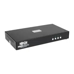
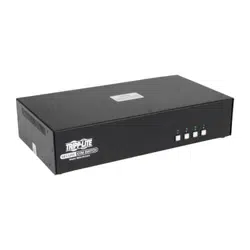
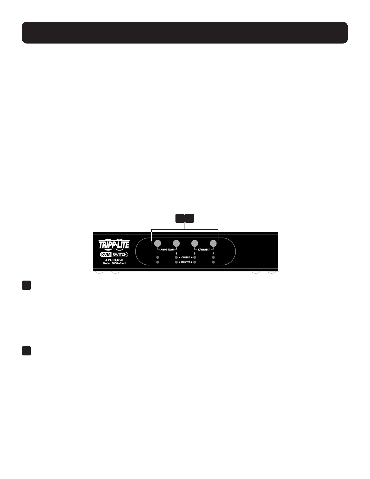
Front Panel
1
Port Selection Pushbuttons
• To bring the KVM focus to the computer attached to its corresponding port, press and release the port-selection
pushbutton. The port LED will illuminate bright orange.
• To initiate Auto Scan mode, press and hold pushbuttons 1 and 2 for two seconds.
• To stop Auto Scan mode, press and release either port selection pushbutton (1 or 2). The KVM focus will go to the
computer attached to the corresponding port of the switch you pressed.
• To perform a keyboard/mouse reset, simultaneously press and hold pushbuttons 3 and 4 for two seconds.
2
Port LEDs
• The LED will dimly illuminate orange to indicate a computer is connected to its corresponding port.
• The LED will brightly illuminate orange to indicate the computer attached to its corresponding port currently has the
focus.
• The LED will flash when a port is currently being accessed in Auto Scan mode.
• All LEDs will flash to indicate Firmware Upgrade mode is in effect.
4. Features
1 2
6
4. Features
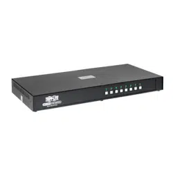
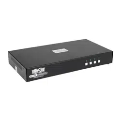
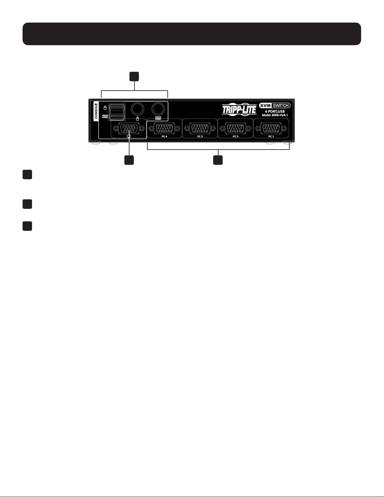
Rear Panel
1
Console Keyboard and Mouse Ports
• The cables from your USB or PS/2 console keyboard and USB or PS/2 console mouse plug in here. Each
connector is marked with an appropriate icon to indicate itself.
2
Console Monitor Port
• The cable from your VGA console monitor plugs into this port.
3
KVM Port Section
• Each KVM port section is comprised of a single female SPHD- 18 port, which incorporates both the USB, PS/2 and
VGA connection.
1
2 3

7
• Read all of these instructions and save them for future reference.
• Follow all warnings and instructions marked on the device.
• Do not place the device on any unstable surface. If the device falls, serious damage will result.
• Do not use the device near water.
• Do not place the device near or over, radiators or heat registers.
• The device cabinet is provided with slots and openings to allow for adequate ventilation. To ensure reliable operation
and protect against overheating, these openings should never be blocked or covered.
• The device should never be placed on a soft surface such as a bed, sofa of rug. Doing so will block the device’s
ventilation openings. Moreover, the device should not be placed in a built-in enclosure unless adequate ventilation has
been provided.
• Never spill liquid of any type on the device.
• Unplug the device from the wall outlet before cleaning. Use a damp cloth for cleaning. Do not use liquid or aerosol
cleaners.
• The device should be operated from the power source indicated on the marking label. If uncertain of the power
available, consult your dealer or local power company.
• The device is designed for IT power distribution systems up to 230V phase-to-phase voltage.
• As an added safety feature, the device is equipped with a 3-wire grounding type plug. If unable to insert the plug into the
outlet, contact an electrician to replace the obsolete outlet. Do not attempt to plug into a two-prong ungrounded outlet.
Always follow local/national wiring codes.
• Do not allow anything to rest on the power cord or cables. Route the power cord and cables to avoid them being
stepped on or tripped over.
• If an extension cord is used with this device, ensure the total ampere ratings of all products used on the extension cord
do not exceed its rated ampere rating. Also ensure all products plugged into the wall outlet does not exceed a total of 15
amperes.
• Consideration should be given to the connection of equipment and the supply circuit, as well as what effect overloading
the supply circuit might have on overcurrent protection and supply wiring.
• To help protect the system from unexpected transient increases and decreases in electrical power, use a Tripp Lite
Surge Protector, Line Conditioner, or Uninterruptible Power Supply (UPS).
• Position system cables and power cables carefully so nothing rests on any cables.
• When connecting or disconnecting power to hot pluggable power supplies, observe the following guidelines:
– Install the power supply before connecting the power cable to the power supply.
– Unplug the power cable before removing the power supply.
– If the system has multiple sources of power, disconnect power from the system by unplugging all power cables from
the power supplies.
• Never push objects of any kind into or through cabinet slots. They may touch dangerous voltage points or short out
parts resulting in a risk of fire or electrical shock.
• Do not attempt to service the device; refer all servicing to qualified service personnel.
5. Important Safety Instructions

8
5. Important Safety Instructions
• If the following conditions occur, unplug the device from the wall outlet and bring it to qualified service personnel for
repair:
– The power cord or plug has become damaged or frayed.
– Liquid has been spilled into the device.
– The device has been exposed to rain or water.
– The device has been dropped, or the cabinet has been damaged.
– The device exhibits a distinct change in performance, indicating a need for service.
– The device does not operate normally when the operating instructions are followed.
• Only adjust controls covered in the operating instructions. Improper adjustment of other controls may result in damage
that will require extensive work by a qualified technician to repair.
• Use of this equipment in life support applications where failure of this equipment can reasonably be expected to cause
the failure of the life support equipment or to significantly affect its safety or effectiveness is not recommended.
9
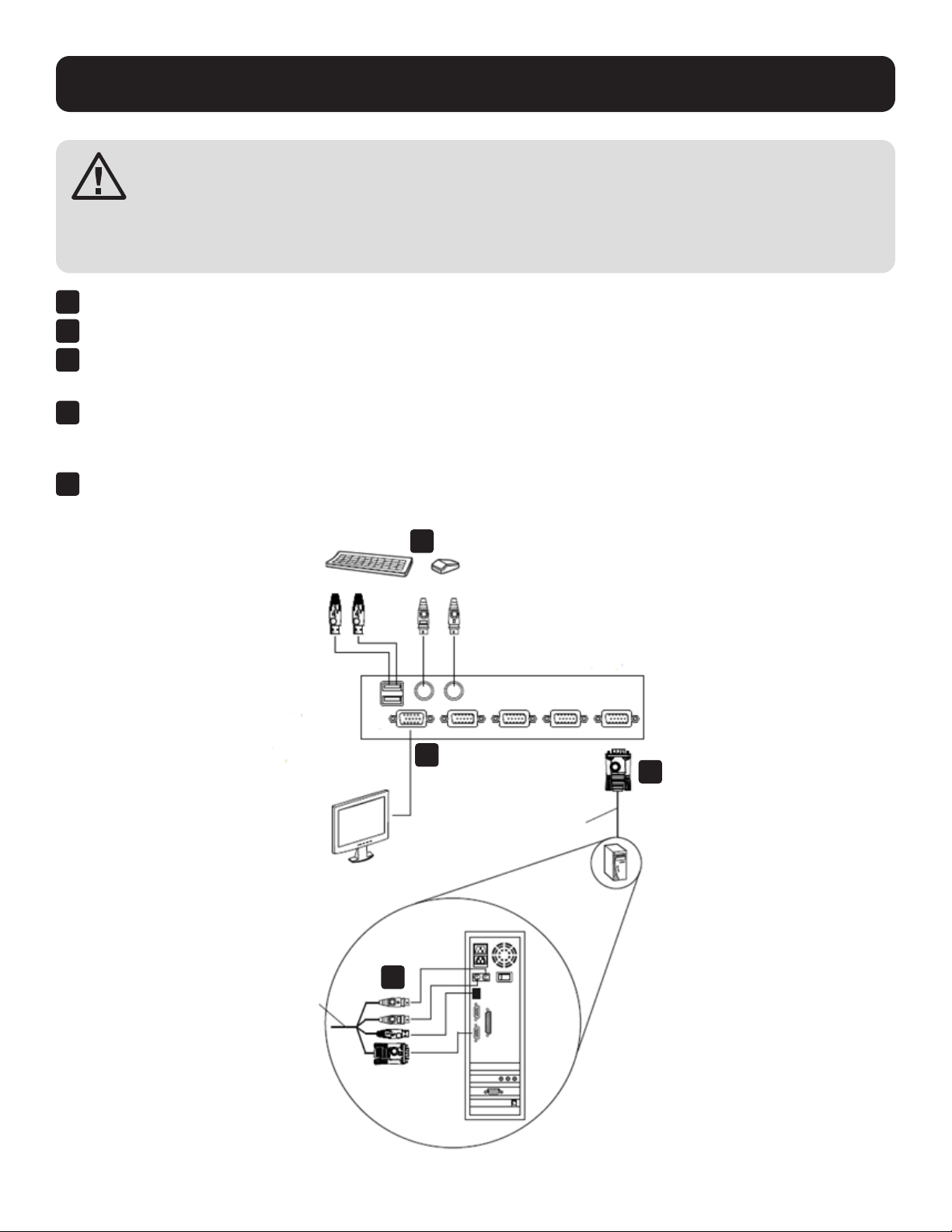
6. Installation
Review all information in the Important Safety Instructions section before proceeding.
• To prevent damage to your installation from power surges or static electricity, make sure all connected
devices are properly grounded.
• Make sure power to all the devices you will be installing are turned off. You must unplug the power cords of
any computers that have the Keyboard Power On function.
1
Plug your keyboard and mouse into the USB or PS/2 console ports located on the unit’s rear panel.
2
Plug your console monitor into the VGA console port located in the unit’s rear panel and power on the monitor.
3
At the other end of the cable, plug the USB or PS/2 and VGA connectors into their respective ports on the computer.
Note: If you are using a combo console, plug in both the USB and PS/2 connectors.
4
If you choose to use external power, plug the power adapter into an AC power source, then plug the power adapter
cable into the switch’s power Jack.
Note: The power adapter should be DC 5V (positive inside/negative outside).
5
Power on the computers.
Note: Make sure the computers and devices the B006-VU4-1 connects to are also properly grounded.
1
2
3
4
Rear View
Cable Set
Cable Set
and / or

10
7. Basic Operation
There are three convenient methods to access the computers:
Manual – Pressing the port selection pushbuttons located on the unit’s front panel.
Mouse – Clicking the scroll wheel of the USB mouse.
Hotkeys – Entering combinations from the keyboard.
7.1 Manual Switching
Manual Port Selection
• Press and release a port selection pushbutton to bring the KVM focus to the computer attached to its corresponding
port. The Port LED will illuminate bright orange.
• Press and hold port selection pushbutton 1 and 2 for more than 2 seconds to start Auto Scan Mode.
• Press and release either port selection pushbutton (1 or 2) to stop Auto Scan Mode. The KVM focus goes to the
computer attached to the corresponding port of the switch you pressed.
• Press port selection pushbuttons 3 and 4 simultaneously for 2 seconds to perform a keyboard and mouse reset.
Manual Port Switching
The B006-VU4-1 supports the very latest in mouse port-switching. Simply double-click the scroll wheel of your USB
mouse to cycle through the ports.
Notes:
• This feature is only supported by USB 3-key scroll wheel mice.
• The default setting is disabled.
• This feature is only supported when Mouse Emulation is enabled. See Mouse Port-switching for additional details.
7.2 Powering Off and Restarting
If it becomes necessary to power off the B006-VU4-1, before restarting you must do the following:
1. Shut down all computers attached to the switch.
2. Unplug the switch’s power adapter cable.
3. Wait 10 seconds, then plug in the switch’s power adapter cable.
4. Once the switch is up, power on the computers.
7.3 Port ID Numbering
Each KVM port section on the B006-VU4-1 switch is assigned a port number. The port numbers are marked on the rear
panel of the switch. The Port ID of a computer is derived from the KVM port number it is connected to. For example, a
computer connected to KVM port 2 has a Port ID of 2. The Port ID is used to specify which computer gets the KVM focus
with the Hotkey port selection method.
7.4 Alternative Manual Port Selection
When Hotkey Setting Mode has been activated, pressing [S] will invoke the alternative front panel pushbutton manual port
selection function as follows:
• Press a port selection pushbutton once to bring the KVM focus to the computer attached to its corresponding port.
• Press and hold port selection pushbuttons 1 and 2 for more than 2 seconds to start Auto Scan Mode.
• Press port selection pushbuttons 3 and 4 simultaneously for 2 seconds to perform a keyboard and mouse reset.

11
8. Hotkey Operation
B006-VU4-1 provides an extensive, easy-to-use hotkey function that makes it convenient to control and configure your
KVM installation from the keyboard.
8.1 Port Switching
All port switches begin with tapping the Scroll Lock key twice. The tables below describe the actions that each
combination performs.
Note: If using the Scroll Lock key conicts with other programs running on the computer, the Ctrl key can be used, instead. See
Alternate Port Switching Keys for details.
8.2 Cycling Through the Ports
Hotkey Action
[Scroll Lock] [Scroll Lock] [Enter] Brings the KVM focus from the port that currently has the
KVM focus to the next port on the installation (1 to 2; 2 to
3; 3 to 4; 4 to 1).
Going Directly to a Port
Hotkey Action
[Scroll Lock] [Scroll Lock] [n] [Enter] Brings the KVM focus to the computer attached to the port
corresponding to the specified Port ID.
Note: The n stands for the computer’s Port ID number (1, 2, 3, or 4). Replace the n with the appropriate Port ID when entering hotkey
combinations.
8.3 Auto Scanning
The B006-VU4-1 Auto Scan feature automatically cycles the KVM focus through the computer ports at regular intervals.
This allows you to monitor the computer activity without having to take the trouble of switching from port to port manually.
Hotkey Action
[Scroll Lock] [Scroll Lock] [A] [Enter] Invokes Auto Scan. The KVM focus cycles from port to port
at 5 second intervals. Five second intervals is the Default
setting.
[Scroll Lock] [Scroll Lock] [A] [Enter] [n] The KVM focus cycles from port to port at n second
intervals.
Replace the n with a number between 1 and 4 when
entering this hotkey combination to set the number of
seconds that the B006-VU4-1 should dwell on a port
before moving on to the next, as follows:
1 = 3 seconds
2 = 5 seconds (default)
3 = 10 seconds
4 = 20 seconds
Notes:
• While Auto Scan Mode is in eect, ordinary keyboard and mouse functions are suspended – only Auto Scan Mode compliant
keystrokes and mouse clicks can be input. You must exit Auto Scan Mode to regain normal control of the console.
• Although the video focus switches from port to port, the keyboard and mouse do not switch. They stay at the port they were on when
Auto Scanning started.
• To exit Auto Scan Mode, press the Esc key or the Spacebar.

12
8. Hotkey Operation
8.4 Hotkey Setting Mode
Hotkey Setting Mode is used to set up your B006-VU4-1 switch configuration. All operations begin with invoking Hotkey
Setting Mode.
Invoking Hotkey Setting Mode
To invoke Hotkey Mode:
1. Press and hold down [Num Lock].
2. Press and release [-].
3. Release [Num Lock].
Notes:
• There is an alternate key combination to invoke Hotkey Setting Mode.
• The minus key must be released within one half second, otherwise Hotkey invocation is canceled.
When Hotkey Mode is active, the Caps Lock, and Scroll Lock LEDs will flash in succession to indicate Hotkey Mode is in
effect. The LEDs stop flashing and revert to normal status when you exit Hotkey Mode.
Ordinary keyboard and mouse functions are suspended – only Hotkey-compliant keystrokes and mouse clicks can be
input.
At the conclusion of some hotkey operations, you automatically exit hotkey mode. Some operations you must exit
manually. To exit Hotkey Setting Mode manually, press the Esc key or the Spacebar.
8.5 Alternate Hotkey Setting Mode Invocation Keys
An alternate set of Hotkey Setting invocation keys is provided in case the default set conflicts with programs running on
the computers.
To switch to the alternate Hotkey Mode invocation set:
1. Invoke Hotkey Mode.
2. Press and release [H].
The Hotkey Mode invocation keys become the Ctrl key (instead of Num Lock) and the F12 key (instead of minus).
Note: This procedure is a toggle between the two methods. To revert back to the original Hotkey Mode invocation keys, invoke Hotkey
Setting Mode, then press and release the H key again.
8.6 Alternate Port Switching Keys
The port switching activation keys can be changed from tapping the Scroll Lock key twice ([Scroll Lock] [Scroll Lock]) to
tapping the Ctrl key twice ([Ctrl] [Ctrl]).
To change the port switching activation keys:
1. Invoke Hotkey Setting Mode.
2. Press and release [T].
Note: This procedure is a toggle between the two methods. To revert back to the original [Scroll Lock] [Scroll Lock] method, invoke
Hotkey Mode, then press and release the T key again.

13
8. Hotkey Operation
8.7 Keyboard Language
To change the keyboard language:
1. Invoke Hotkey Mode.
2. Press [F6] [nn] [Enter].
Note: nn is a two-digit number that represents the keyboard language code (US English: 33; French: 08; Japanese: 15).
8.8 Keyboard Operating Platform
The B006-VU4-1 default port configuration is for a PC-compatible keyboard operating platform. If your console uses a PC
compatible keyboard and you have a Mac attached to a port, for example, you can change the port’s keyboard operating
platform configuration so that the PC compatible keyboard emulates the Mac keyboard.
The procedure is as follows:
1. Bring the KVM focus to the port you want to set.
2. Invoke Hotkey Mode.
3. Press and release the appropriate Function key (see table below). After completing this procedure, you automatically
exit Hotkey Mode.
Function Key Operation
[F2] Enables Mac keyboard emulation, see Mac Keyboard
section for details.
[F3] Enables Sun keyboard emulation, see Sun Keyboard
section for details.
[F10] Automatically detects and sets the keyboard operating
platform.
8.9 List Switch Settings
To see a listing of the current switch settings:
1. Open a text editor or word processor and place the cursor in the page window.
2. Invoke Hotkey Mode.
3. Press and release [F4] to display the settings.
8.10 USB Reset
If the USB loses focus and needs to be reset:
1. Invoke Hotkey Mode.
2. Press and release [F5].
8.11 Hotkey Buzzer Control
The Buzzer can be hotkey toggled on and off. To toggle the buzzer:
1. Invoke Hotkey Mode.
2. Press and release [B].

14
8. Hotkey Operation
8.12 Disable Port Switching Keys
To disable the Port Switching Keys ([Scroll Lock] [Scroll Lock] / [Ctrl] [Ctrl]):
1. Invoke Hotkey Mode.
2. Press [X] [Enter].
Note: This procedure is a toggle. To enable the Port Switching keys, repeat steps 1 and 2.
8.13 Firmware Upgrade Mode
To set the B006-VU4-1 to Firmware Upgrade Mode:
1. Invoke Hotkey Setting Mode.
2. Key in: upgrade
3. Press [Enter].
All front panel LEDs (green and orange) flash to indicate Firmware Upgrade Mode is in effect.
Note: To exit Firmware Upgrade Mode, you must power off the switch.
8.14 Restore Default Settings
To reset the B006-VU4-1 to its default hotkey settings:
1. Invoke Hotkey Setting Mode.
2. Press [R] [Enter].
See Hotkey Default Settings section for additional details.
8.15 Mouse Port-Switching
To enable/disable the Mouse Port-switching function, do the following:
1. Invoke Hotkey Setting Mode.
2. Press [W].
Notes:
• This procedure is a toggle.
• The default setting is disabled.
• The feature is only supported when mouse emulation is enabled.
8.16 Mouse Emulation Control
To toggle between mouse emulation enable and disable:
1. Invoke Hotkey Setting Mode.
2. Press [M].
8.17 Keyboard Emulation Control
To toggle between keyboard emulation enable and disable:
1. Invoke Hotkey Setting Mode.
2. Press [N].
Note: When keyboard emulation is disabled, the [m], [w], [F2], [F3], [F10], [F4], [F5], and [F6] hotkeys are disabled.

15
8. Hotkey Operation
8.18 Other OS Mode
To reset keyboards and mice for operating systems that do not support USB 2.0:
1. Invoke Hotkey Setting Mode.
2. Press [F1].
8.19 Hotkey Setting Mode Summary Table
After invoking Hotkey Setting Mode, key in one of the following to perform the corresponding function:
Key Function
[F1] Resets keyboard and mouse under operating systems that
do not support USB 2.0.
[F2] Enables Mac keyboard emulation.
[F3] Enables Sun keyboard emulation.
[F4] Prints the switch’s current settings via text editor or word
proessor.
[F5] Performs a reset on all USB devices.
[F6] [nn] [Enter] Sets the keyboard language layout.
Note: nn is a 2-digit number that represents one of the following
keyboard language codes: US English 33; French 08; Japanese
15.
[F10] Auto detects the keyboard operating platform.
[B] Toggles the beeper on/off.
[D] Display resolution optimization and boot-up display
enhancement for faster switching.
[H] Toggles the Hotkey Setting Mode Activation Command
between [Num Lock] [-] and [Ctrl] [F12].
[M] Enables/disables mouse emulation.
[N] Enables/disables keyboard emulation.
[R] [Enter] Resets the hotkey settings to their default status.
[T] Toggles between the default [Scroll Lock] [Scroll Lock] and
alternate [Ctrl] [Ctrl] port switching keys.
[u] [p] [g] [r] [a] [d] [e] [Enter] Invoke Firmware Upgrade Mode.
[W] Enables/disables mouse
[X] [Enter] Enables/disables the port switching keys.
16
9. Keyboard Emulation
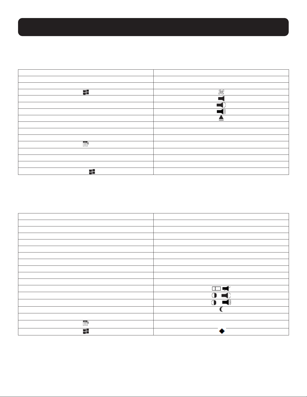
9.1 Mac Keyboard
The PC-compatible (101/104 key) keyboard can emulate the functions of the Mac keyboard. The emulation mappings are
listed in the table below.
PC Keyboard Mac Keyboard
[Shift] Shift
[Ctrl] Ctrl
[Ctrl] [1]
[Ctrl] [2]
[Ctrl] [3]
[Ctrl] [4]
[Alt] Alt
[Print Screen] F13
[Scroll Lock] F14
=
[Enter] Return
[Backspace] Delete
[Insert] Help
[Ctrl]
F15
Note: When using key combinations, press and release the first key (Ctrl), then press and release the activation key.
9.2 Sun Keyboard
The PC-compatible (101/104 key) keyboard can emulate the functions of the Sun keyboard when the Control key [Ctrl] is
used in conjunction with other keys. The corresponding functions are shown in the table below.
PC Keyboard Sun Keyboard
[Ctrl] [T] Stop
[Ctrl] [F2] Again
[Ctrl] [F3] Props
[Ctrl] [F4] Undo
[Ctrl] [F5] Front
[Ctrl] [F6] Copy
[Ctrl] [F7] Open
[Ctrl] [F8] Paste
[Ctrl] [F9] Find
[Ctrl] [F10] Cut
[Ctrl] [1]
[Ctrl] [2]
-
[Ctrl] [3]
+
[Ctrl] [4]
[Ctrl] [H] Help
Compose
Note: When using key combinations, press and release the first key [Ctrl], then press and release the activation key.
17
10. Firmware Upgrade Utility
The Windows-based Firmware Upgrade Utility (FWUpgrade.exe) provides a smooth, automated process for upgrading the
KVM switch’s firmware. The Utility comes as part of a Firmware Upgrade Package that is specific for each device. Check
the web site regularly to find the latest packages and information relating to them: http://www.tripplite.com.
Before you Begin
1
From a computer that is not part of your KVM installation, go to our internet support site and choose the model name
that relates to your device B006-VU4-1 to get a list of available Firmware Upgrade Packages.
2
Choose the Firmware Upgrade Package you want to install (usually the most recent) and download it to your
computer.
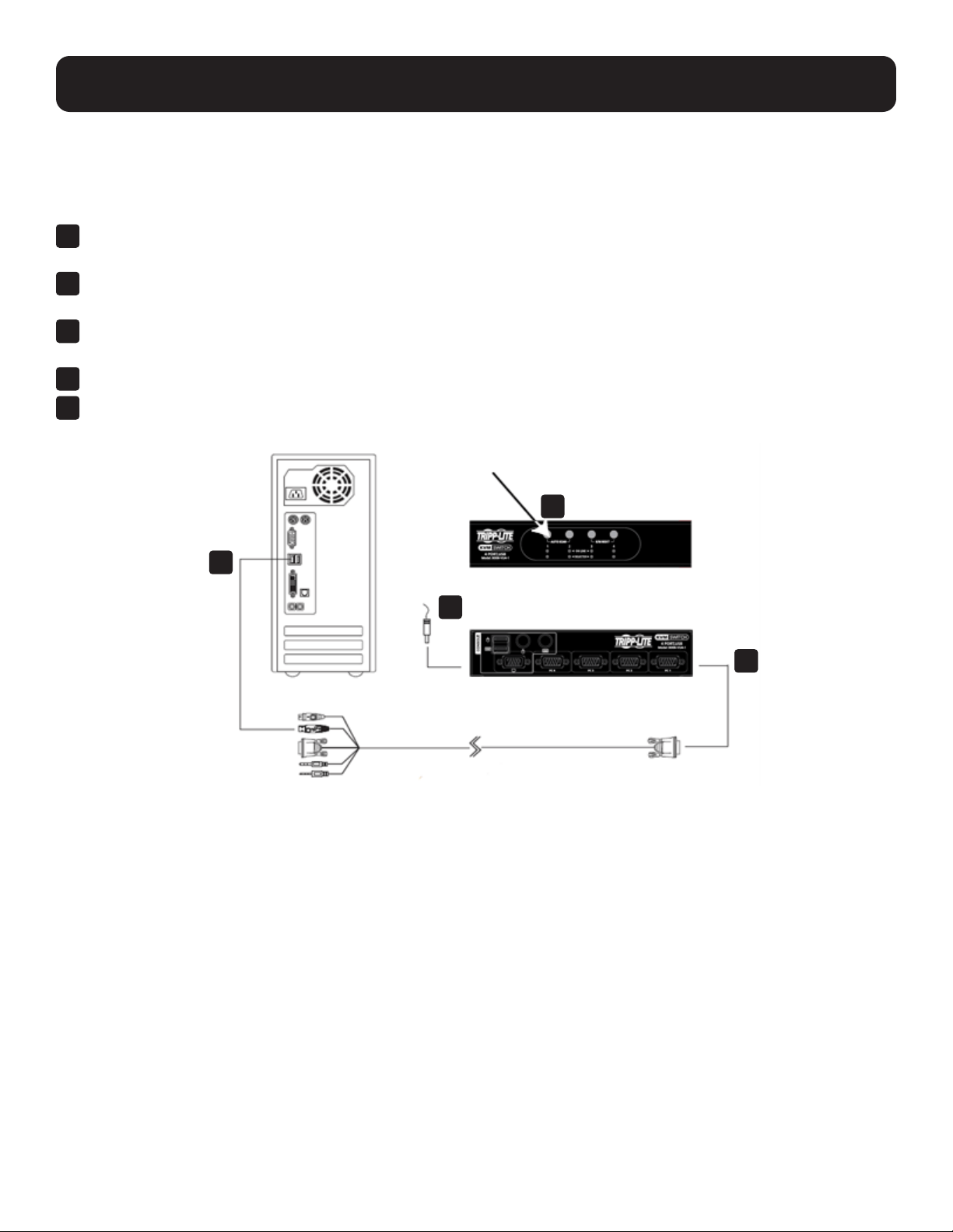
3
DisconnecttheB006-VU4-1fromyourKVMinstallationandpowerito.ConnectoneofthecustomKVMcableset’s
Type A USB connectors to a USB hub port on your computer.
4
At the other end of the KVM cable set, connect the video connector to the Port 1 KVM section.
5
Invoke Firmware Upgrade Mode (see Firmware Upgrade Mode).ThefrontpanelLEDswillashtoindicatethat
FirmwareUpgradeModeisineect.
3
5
5
4
18
10. Firmware Upgrade Utility
Initiating the Firmware Upgrade
1. Run the downloaded Firmware Upgrade Package file by double clicking the file icon or using a command line to enter
the full path. The Firmware Upgrade Utility Welcome screen will appear.
2. Read the License Agreement and enable the I Agree radio button.
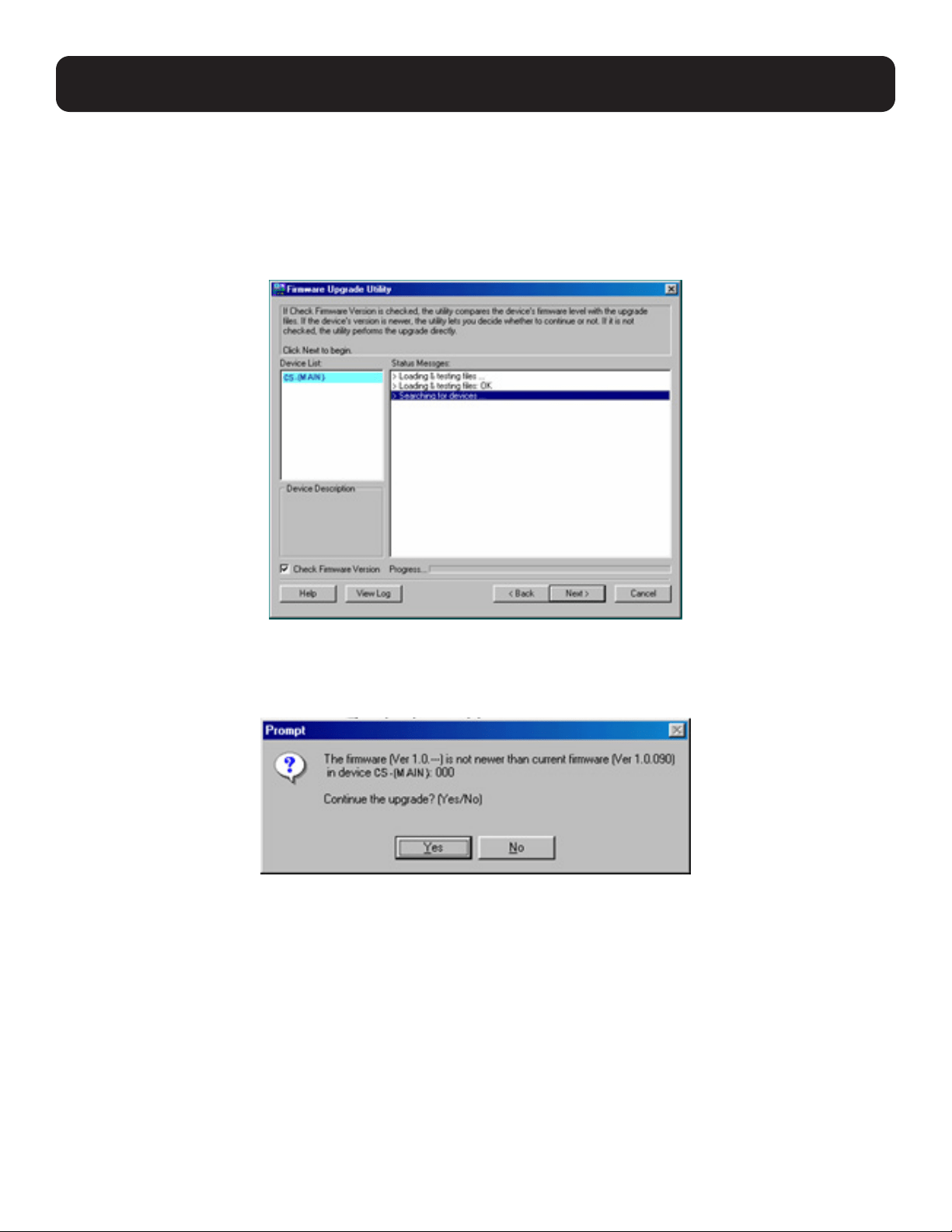
3. Click Next. The Firmware Upgrade Utility main screen appears. The Utility inspects your installation. All the devices
capable of being upgraded by the package are listed in the Device List panel.
4. As you select a device in the list, its description appears in the Device Description panel. Once you have made your
device selection(s), click Next to perform the upgrade.
If you enabled Check Firmware Version, the Utility compares the device’s firmware level with that of the upgrade files.
If the device’s version is higher than the upgrade version, a dialog box gives you the option to Continue or Cancel.
If you didn’t enable Check Firmware Version, the Utility installs the upgrade files without checking whether or not they
are a higher level.
19
10. Firmware Upgrade Utility
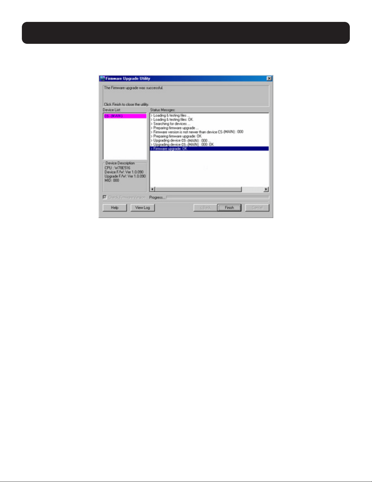
Upgrade Successful
After the upgrade has completed, a screen will appear to inform you that the procedure was successful:
Click Finish to close the Firmware Upgrade Utility.
After a successful completion, the B006-VU4-1 exits Firmware Upgrade Mode and resets itself.
Upgrade Failed
If the Upgrade Succeeded screen does not appear, the upgrade failed to complete successfully, in which case you should
do the following:
1. Press and hold the Port 1 selection pushbutton. While you are holding the pushbutton, connect the B006-VU4-1 to the
computer using the USB cable of the custom cable set to enter Firmware Upgrade Mode. The front panel LEDs will
flash to indicate that Firmware Upgrade Mode is in effect.
2. Run the upgrade again. See Starting the Upgrade for details.
20
11. Technical Support
Online technical support – including troubleshooting, documentation, and software updates:
tripplite.com/support/technical-support-request
Telephone support: 773.869.1234.
When you contact us, please have the following information ready:
1. Product model number, serial number and date of purchase.
2. Your computer configuration, including operating system, revision level, expansion cards and software.
3. Any error messages displayed at the time the error occurred.
4. The sequence of operations that led up to the error.
5. Any other information you feel may be of help.
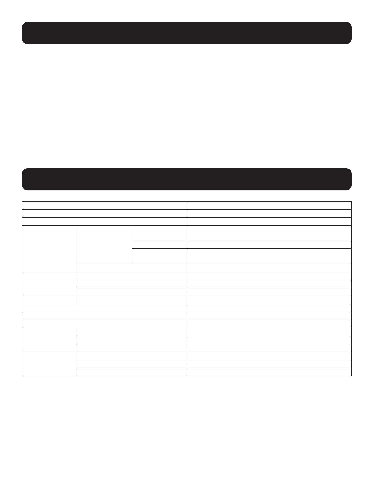
12. Specifications
Function B006-VU4-1
Computer Connections 4
Port Selection Front Panel Pushbuttons; Hotkey, USB Mouse
Connectors Console Ports Keyboard 1 x USB Type A Female (Black), 1 x 6-pin Mini-DIN Female
(Purple)
Video 1 x HDB-15 Female (Blue)
Mouse 1 x USB Type A Female (Black), 1 x 6-pin Mini-DIN Female
(Green)
KVM Ports 4 x HD-18 Female (Yellow)
Switches Selected 4 x Pushbutton
LEDs On Line 4 (Orange)
Selected 4 (Green)
Emulation Keyboard / Mouse USB
Video 2048 x 1536 @ 60 Hz; DDC2B
Scan Interval 3, 5, 10, 20 secs. (5 secs. default)
Power Consumption DC 5V, 1.2 W
Environment Operating Temp. 32~122ºF/ 0~50ºC
Storage Temp. -4~140ºF / -20~60ºC
Humidity 0–80% RH, Non-condensing
Physical
Properties
Housing Metal
Weight 1.7 lb. / 0.77 kg
Dimensions (L x W x H) 8.3 x 3.4 x 2.2 in. / 210 x 87 x 55 mm

21
13. Troubleshooting
Operation problems can be due to a variety of causes. The first step in solving them is to make sure all cables are
securely attached and seated completely in their sockets. In addition, updating the product’s firmware may solve problems
that have been discovered and resolved since the prior version was released. If your product is not running the latest
firmware version, we strongly recommend that you upgrade. See Firmware Upgrade Utility, for additional details.
Symptom Possible Cause Action
Erratic behavior Unit not receiving enough power. Use a DC 5V power adapter if you are
not already using one. If you are
already using a power adapter, check
that it matches the system
specifications, and that it is plugged in
and functioning properly.
Keyboard and/or mouse need to be
reset.
Unplug the cable(s) from the console
port(s), then plug it/them back in.
No connection to the computer. Check the cable from the switch to the
computer to make sure it is properly
connected.
KVM switch needs to be reset. Power off all devices on the
installation; power off the KVM switch;
wait five seconds, then power up.
USB devices not responding USB ports need to be reset. Unplug the device’s USB cable from
the USB port on the switch’s rear
panel, then plug it back in.
Use the USB Reset hotkey
combination, to reset the USB ports.
Cannot switch ports by pressing [Scroll
Lock] twice.
Keyboard is incompatible with Scroll
Lock invocation.
Switch to the Alternate Hotkey Setting
Mode invocation keys.
Monitor does not display after KVM
cable set is hot plugged.
Some graphics cards are incompatible
with cable set hot plugging.
Power off all devices on the
installation; power off the switch;
confirm all KVM cables are properly
connected; power on the switch; power
on the computers.
When switching ports, the monitor
does not display.
Monitor is new or this is the first-time
installation.
Switch ports again and wait two or
more seconds for the PC’s EDID to
pass to the monitor.
The PC’s EDID has not passed
through to the monitor when switching
ports.
Use the [d] hotkey to invoke Video
Sync one more time or switch to
another PC to reconnect the switch.
See Hotkey Setting Mode Summary
Table.

22
13. Troubleshooting
13.1 Hotkey Default Settings
Setting Hotkey Default
Port Switching [T] [Scroll Lock] [Scroll Lock]
Invoking Hotkey Mode [H] [Number Lock] [-]
Auto Scan Interval [Scroll Lock] [Scroll Lock] [A] [Enter] 5 seconds
Keyboard Operating Platform [F10] PC-compatible
Keyboard Emulation [N] Enabled
Mouse Emulation [M] Enabled
Mouse Port-Switching [W] Disabled
Display Resolution Optimization [D]
Port Switching Keys (On / Off) [X] [Enter] Enabled
Beeper [B] Enabled
Keyboard Language [F6] [nn] [Enter]
Note: nn is the language number.
English

23
14. Warranty and Product Registration
3-YEAR LIMITED WARRANTY
Seller warrants this product, if used in accordance with all applicable instructions, to be free from original defects in material and workmanship for a
period of three (3) years from the date of initial purchase. If the product should prove defective in material or workmanship within that period, Seller will
repair or replace the product, in its sole discretion. Service under this Warranty can only be obtained by your delivering or shipping the product (with all
shipping or delivery charges prepaid) to: Tripp Lite; 1111 W. 35th Street; Chicago IL 60609; USA. Seller will pay return shipping charges. Visit tripplite.
com/support before sending any equipment back for repair. THIS WARRANTY DOES NOT APPLY TO NORMAL WEAR OR TO DAMAGE RESULTING
FROM ACCIDENT, MISUSE, ABUSE OR NEGLECT. SELLER MAKES NO EXPRESS WARRANTIES OTHER THAN THE WARRANTY EXPRESSLY
SET FORTH HEREIN. EXCEPT TO THE EXTENT PROHIBITED BY APPLICABLE LAW, ALL IMPLIED WARRANTIES, INCLUDING ALL
WARRANTIES OF MERCHANTABILITY OR FITNESS, ARE LIMITED IN DURATION TO THE WARRANTY PERIOD SET FORTH ABOVE; AND THIS
WARRANTY EXPRESSLY EXCLUDES ALL INCIDENTAL AND CONSEQUENTIAL DAMAGES. (Some states do not allow limitations on how long an
implied warranty lasts, and some states do not allow the exclusion or limitation of incidental or consequential damages, so the above limitations or
exclusions may not apply to you. This Warranty gives you specific legal rights, and you may have other rights which vary from jurisdiction to
jurisdiction). Tripp Lite; 1111 W. 35th Street; Chicago IL 60609; USA WARNING: The individual user should take care to determine prior to use whether
this device is suitable, adequate or safe for the use intended. Since individual applications are subject to great variation, the manufacturer makes no
representation or warranty as to the suitability or fitness of these devices for any specific application.
PRODUCT REGISTRATION
Visit tripplite.com/warranty today to register your new Tripp Lite product. You’ll be automatically entered into a drawing for a chance to win a FREE
Tripp Lite product!*
*No purchase necessary. Void where prohibited. Some restrictions apply. See website for details. Use of this equipment in life support applications
where failure of this equipment can reasonably be expected to cause the failure of the life support equipment or to significantly affect its safety or
effectiveness is not recommended. Regulatory
Compliance Identification Numbers
For the purpose of regulatory compliance certifications and identification, your Tripp Lite product has been assigned a unique series number. The series
number can be found on the product nameplate label, along with all required approval markings and information. When requesting compliance
information for this product, always refer to the series number. The series number should not be confused with the marking name or model number of
the product
FCC Notice, Class B
This device complies with part 15 of the FCC Rules. Operation is subject to the following two conditions: (1) This device may not cause harmful
interference, and (2) this device must accept any interference received, including interference that may cause undesired operation. Note: This
equipment has been tested and found to comply with the limits for a Class B digital device, pursuant to part 15 of the FCC Rules. These limits are
designed to provide reasonable protection against harmful interference in a residential installation. This equipment generates, uses and can radiate
radio frequency energy and, if not installed and used in accordance with the instructions, may cause harmful interference to radio communications.
However, there is no guarantee that interference will not occur in a particular installation. If this equipment does cause harmful interference to radio or
television reception, which can be determined by turning the equipment off and on, the user is encouraged to try to correct the interference by one or
more of the following measures:
• Reorient or relocate the receiving antenna.
• Increase the separation between the equipment and receiver. • Connect the equipment into an outlet on a circuit different from that to which the
receiver is connected.
• Consult the dealer or an experienced radio/TV technician for help. Any changes or modifications to this equipment not expressly approved by
Tripp Lite could void the user’s authority to operate this equipment.
WEEE Compliance Information for Tripp Lite Customers and Recyclers (European Union)
Under the Waste Electrical and Electronic Equipment (WEEE) Directive and implementing regulations, when customers buy new electrical and
electronic equipment from Tripp Lite they are entitled to:
• Send old equipment for recycling on a one-for-one, like-for-like basis (this varies depending on the country)
• Send the new equipment back for recycling when this ultimately becomes waste.
Tripp Lite has a policy of continuous improvement. Specifications are subject to change without notice. Photos and illustrations may differ slightly from
actual products.

24
1111 W. 35th Street, Chicago, IL 60609 USA • tripplite.com/support
22-10-225 93461A_RevA