Loading ...
Loading ...
Loading ...
26
REACH-INS & ROLL-INS
OPERATIONS MANUAL
DIGITAL THERMOMETER W/ALARM
AND BATTERY BACKUP
The optional NSF-approved digital thermometer with alarm and
battery backup is prominently located on the front grill. Precise
temperature indication is provided from a remote sensing
bulb, located inside the cabinet. (Note: A separate electronic
temperature control unit is located behind the grill. Refer to the
Operation section on Electronic Control, for temperature set-
tings adjustments.) A 9-volt alkaline battery must be connected
to the back of the display, for temperature indication during a
power outage. Additional features include:
• Large, easy to read LED display (24-Volt AC)
• Data logging highest and lowest temp
• Flashing display visual alarm
• Battery backup (9-volt battery not included)
• Adjustable alarm set points (2)
• Alarm reset switch (manual, automatic)
• NO/NC alarm relay contacts (1 amp)
• Switchable alarm delay (0 or 45 minutes)
• 24VAC output for audible alarm (by others)
• Switchable audible silencing (none, 5 or 45min)
To replace the doors, reverse the steps above, making sure the
door seats properly over the locating studs on the roller track.
If your sliding door does not close firmly, remove the doors,
starting with the outer door, as described above. Check the bot-
tom of the door, mounting frame channel, and rollers to make
sure they are clean and free of debris. If the rollers are damaged
or do not turn freely, contact the factory to order replacement
parts. The tension on the self-closing spring is adjustable, to
provide quicker and firmer closing, or to provide slower and
more gentle movement. Remove the screw attaching the end
of the self-closing spring to the top of the door. Note that there
are (3) threaded holes provided in the top of the door. To adjust
the door so it closes slower, reattach the spring at a position
closer to the handle side of the door. For a faster, firmer closing,
relocate the spring at a position further away from the handle
side of the door.
If the door does not seal evenly along the handle side when
in the closed position, the tilt of the door is adjustable. A flat
washer can be placed over the locating stud on the top of the
roller track, between the track and the underside of the door, to
level the door. For example: if the door contacts the mounting
frame at the top when it is closed, but there is a gap at the lower
half of the side edge, remove the door as described above. After
lifting the door off the roller track, place a flat washer over the
stud located closest to the handle side of the door. Replace the
door, recheck the seal, and readjust if needed. (To close a gap at
the upper half of the door, place a washer over the locating stud
farthest from the handle side of the door.)
IMPORTANT NOTE: The glass used in sliding or hinged
glass doors is of special, sealed pane design and can
not be replaced with ordinary window or plate glass.
If it becomes necessary to replace the glass, it can be
obtained directly from the factory.
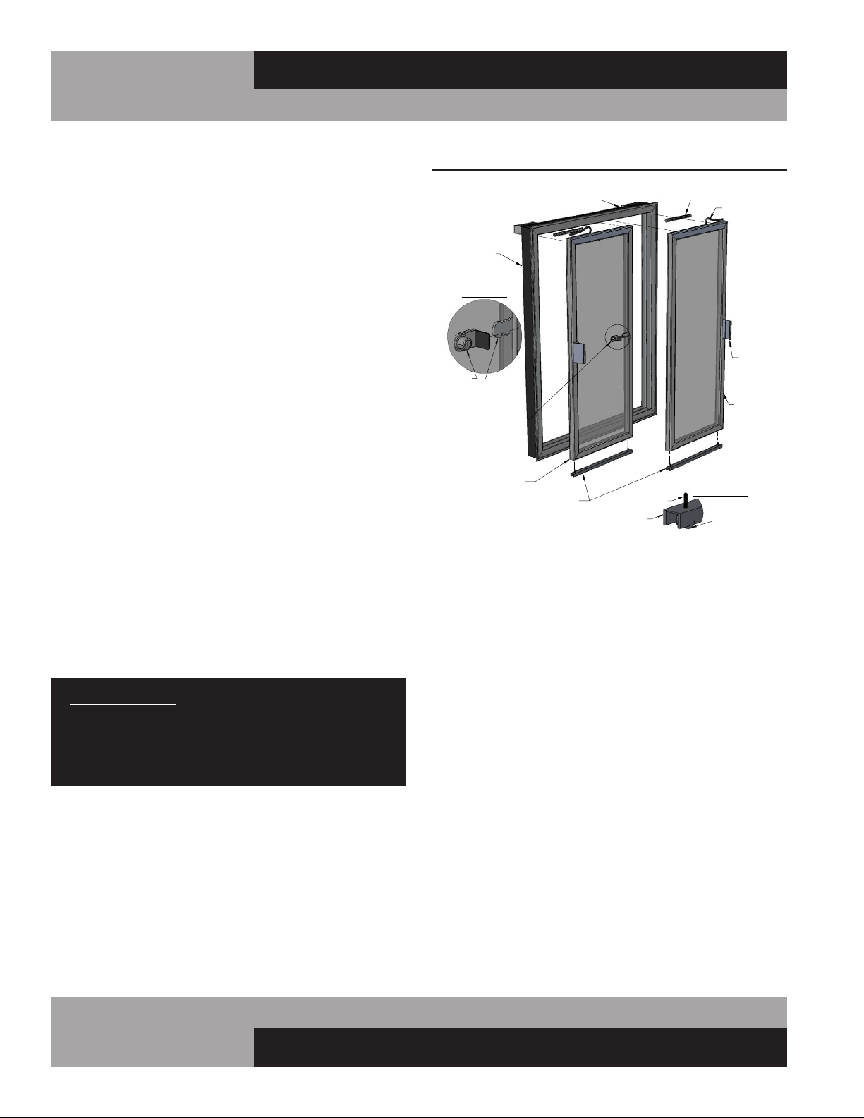
FIGURE 13: Sliding Glass Door Components
LEFT HAND
(INNER)
DOOR
RIGHT HAND
(OUTER)
DOOR
MOUNTING
FRAME
ELECTRICAL RACEWAY
HANDLE
POWER CORD
SPRING
DOOR LOCK
ROLLER DETAIL
LOCATING
STUD
ROLLER
TRACK
RECEIVER
PLATE
LOCK DETAIL
(WHEN PROVIDED)
LOCK
WITH STOP
ROLLER TRACK
Loading ...
Loading ...
Loading ...