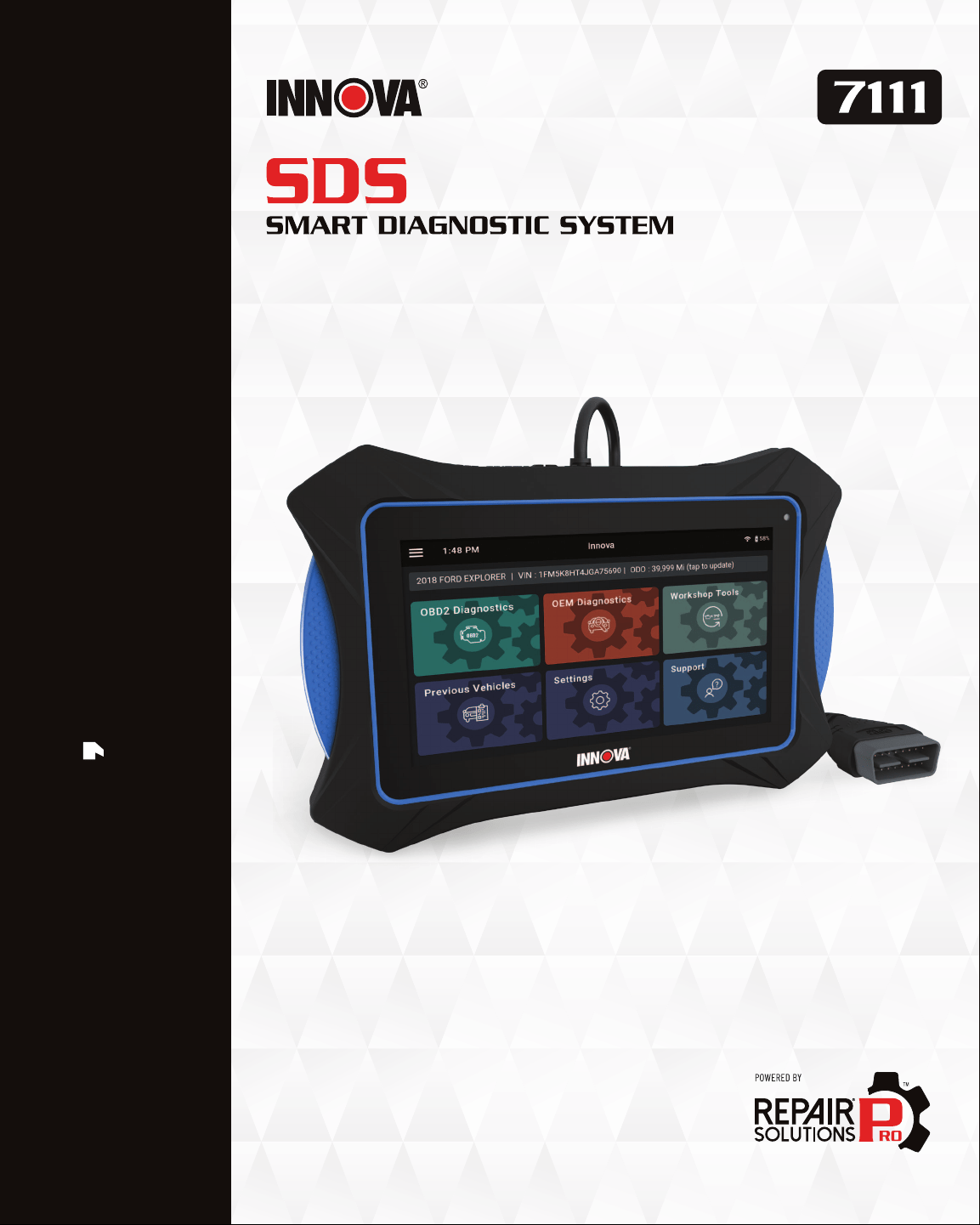
USER S MANUAL
OE-Level Diagnostic Tablet
i
Hello...
On behalf of everyone at INNOVA, we want to welcome you and thank you for purchasing
the INNOVA
®
7111 Smart Diagnostic System (SDS) tablet! Our
2021 Motor Top 20 award
winning tablet includes tons of pro-level features designed to help maximize your OBD2
diagnostic routine. In this manual, we will guide you on how to access a comprehensive library
of time-saving diagnostic and service tools including:
Plus, gain the benet of having unlimited access to real world solutions:
Enjoy using your INNOVA SDS Tablet!
Yours sincerely,
The Innova Technical Team
P.S.: Connect with us to see what we’re up to...
RepairSolutionsPRO™ increases the power of your INNOVA
OBD2 diagnostic tablet by delivering the most complete
automotive repair database with veried xes from ASE
Certied Master Technicians. Get the right x and the right
parts instantly right on your SDS Tablet or mobile device.
; Check Engine Light Diagnostics
; Bi-Directional Active Tests
; Special Functions
; Enhanced Data Stream
; TPMS / Tire Pressure Readings
; Transmission Temperature Readings
; Hybrid Battery Cell Voltage Readings
; EPB / ABS Servicing
; Full OEM Network Scans
; Battery Reset
; Oil Light Reset
; SRS / Safety System Inspection
; 10 OBD II Modes
; Oil Level Checks
; Battery System Check
; Stream Live Data PIDs
; Smog / Emissions Readiness
; ABS Inspections
; OEM Level Diagnostics
; And Much More...
WELCOME TO THE INNOVA FAMILY!

ii
LEGAL INFORMATION � � � � � � � � � � � � � � � � � � � � � � � � � � � � � � � 1
FCC Compliance Statement . . . . . . . . . . . . . . . . . . . . . . . . . . . . . . . . . . . . . . . . . . . . . . . . . . .1
Trademarks. . . . . . . . . . . . . . . . . . . . . . . . . . . . . . . . . . . . . . . . . . . . . . . . . . . . . . . . . . . . . . .1
Patents . . . . . . . . . . . . . . . . . . . . . . . . . . . . . . . . . . . . . . . . . . . . . . . . . . . . . . . . . . . . . . . . . 2
Software Version . . . . . . . . . . . . . . . . . . . . . . . . . . . . . . . . . . . . . . . . . . . . . . . . . . . . . . . . . . 2
California Product Warnings . . . . . . . . . . . . . . . . . . . . . . . . . . . . . . . . . . . . . . . . . . . . . . . . . 2
SAFETY PRECAUTIONS � � � � � � � � � � � � � � � � � � � � � � � � � � � � � �3
Safety First!. . . . . . . . . . . . . . . . . . . . . . . . . . . . . . . . . . . . . . . . . . . . . . . . . . . . . . . . . . . . . . 3
Safety Alert Icons . . . . . . . . . . . . . . . . . . . . . . . . . . . . . . . . . . . . . . . . . . . . . . . . . . . . . . . . . 4
INTRODUCTION � � � � � � � � � � � � � � � � � � � � � � � � � � � � � � � � � �5
Tablet Controls . . . . . . . . . . . . . . . . . . . . . . . . . . . . . . . . . . . . . . . . . . . . . . . . . . . . . . . . . . . 5
Initial Tablet Setup . . . . . . . . . . . . . . . . . . . . . . . . . . . . . . . . . . . . . . . . . . . . . . . . . . . . . . . . 6
Create Your Account . . . . . . . . . . . . . . . . . . . . . . . . . . . . . . . . . . . . . . . . . . . . . . . . . . . . . . . 7
The Home Screen . . . . . . . . . . . . . . . . . . . . . . . . . . . . . . . . . . . . . . . . . . . . . . . . . . . . . . . . . 8
Technical Specications . . . . . . . . . . . . . . . . . . . . . . . . . . . . . . . . . . . . . . . . . . . . . . . . . . . . 9
The RepairSolutionsPRO™ App. . . . . . . . . . . . . . . . . . . . . . . . . . . . . . . . . . . . . . . . . . . . . . . .10
The RSPRO APP Offers… � � � � � � � � � � � � � � � � � � � � � � � � � � � � � � � � � � � � � � �10
Hardware Requirements � � � � � � � � � � � � � � � � � � � � � � � � � � � � � � � � � � � � � � �10
Download the RSPRO App � � � � � � � � � � � � � � � � � � � � � � � � � � � � � � � � � � � � � � �10
Using the RepairSolutionsPRO App � � � � � � � � � � � � � � � � � � � � � � � � � � � � � � � � � � 10
GETTING STARTED � � � � � � � � � � � � � � � � � � � � � � � � � � � � � � � 12
Connecting the Tablet . . . . . . . . . . . . . . . . . . . . . . . . . . . . . . . . . . . . . . . . . . . . . . . . . . . . . .12
AutoLink Connection . . . . . . . . . . . . . . . . . . . . . . . . . . . . . . . . . . . . . . . . . . . . . . . . . . . . . . .12
Scanning a Vehicle . . . . . . . . . . . . . . . . . . . . . . . . . . . . . . . . . . . . . . . . . . . . . . . . . . . . . . . .13
OBD2 DIAGNOSTICS � � � � � � � � � � � � � � � � � � � � � � � � � � � � � � 15
Performing a Scan – OBD2 Diagnostics . . . . . . . . . . . . . . . . . . . . . . . . . . . . . . . . . . . . . . . . .15
TABLE OF CONTENTS

iii
Viewing Scan Results – OBD2 Diagnostics . . . . . . . . . . . . . . . . . . . . . . . . . . . . . . . . . . . . . . .15
Emissions Readiness – Interpreting Results � � � � � � � � � � � � � � � � � � � � � � � � � � � � �16
MIL DTC Code � � � � � � � � � � � � � � � � � � � � � � � � � � � � � � � � � � � � � � � � � � � � � 16
Viewing Freeze Frame Data . . . . . . . . . . . . . . . . . . . . . . . . . . . . . . . . . . . . . . . . . . . . . . . . . . . . . . . . . . . 17
Fix for DTCs (RSPRO) � � � � � � � � � � � � � � � � � � � � � � � � � � � � � � � � � � � � � � � � � 17
Monitor Status � � � � � � � � � � � � � � � � � � � � � � � � � � � � � � � � � � � � � � � � � � � � �18
Viewing Drive Cycle Procedures. . . . . . . . . . . . . . . . . . . . . . . . . . . . . . . . . . . . . . . . . . . . . . . . . . . . . . . . 19
Stored DTC � � � � � � � � � � � � � � � � � � � � � � � � � � � � � � � � � � � � � � � � � � � � � 20
Pending DTC � � � � � � � � � � � � � � � � � � � � � � � � � � � � � � � � � � � � � � � � � � � � � 20
Permanent DTC � � � � � � � � � � � � � � � � � � � � � � � � � � � � � � � � � � � � � � � � � � � 20
Additional Testing Utilities. . . . . . . . . . . . . . . . . . . . . . . . . . . . . . . . . . . . . . . . . . . . . . . . . . 20
Erasing OBD2 DTCs � � � � � � � � � � � � � � � � � � � � � � � � � � � � � � � � � � � � � � � � � 20
OBD Mode Tests � � � � � � � � � � � � � � � � � � � � � � � � � � � � � � � � � � � � � � � � � � � � 21
Inspection/Maintenance Monitor Test (Mode $01). . . . . . . . . . . . . . . . . . . . . . . . . . . . . . . . . . . . . . . . . . 22
Oxygen Sensor (Mode $05) . . . . . . . . . . . . . . . . . . . . . . . . . . . . . . . . . . . . . . . . . . . . . . . . . . . . . . . . . . . . 22
Onboard Diagnostics Mode Test (Mode $06) . . . . . . . . . . . . . . . . . . . . . . . . . . . . . . . . . . . . . . . . . . . . . . 23
Evaporative Test (Mode $08). . . . . . . . . . . . . . . . . . . . . . . . . . . . . . . . . . . . . . . . . . . . . . . . . . . . . . . . . . . 23
Live Data Mode � � � � � � � � � � � � � � � � � � � � � � � � � � � � � � � � � � � � � � � � � � � 24
Viewing Live Data . . . . . . . . . . . . . . . . . . . . . . . . . . . . . . . . . . . . . . . . . . . . . . . . . . . . . . . . . . . . . . . . . . . 24
Recording (Capturing) Live Data . . . . . . . . . . . . . . . . . . . . . . . . . . . . . . . . . . . . . . . . . . . . . . . . . . . . . . . 26
Vehicle Information � � � � � � � � � � � � � � � � � � � � � � � � � � � � � � � � � � � � � � � � � 26
Additional Vehicle Information & Customer Information . . . . . . . . . . . . . . . . . . . . . . . . . . . . . . . . . . . 26
Vehicle ID . . . . . . . . . . . . . . . . . . . . . . . . . . . . . . . . . . . . . . . . . . . . . . . . . . . . . . . . . . . . . . . . . . . . . . . . . . 27
Available Modules . . . . . . . . . . . . . . . . . . . . . . . . . . . . . . . . . . . . . . . . . . . . . . . . . . . . . . . . . . . . . . . . . . . 27
In-Use Performance Tracking (IPT) . . . . . . . . . . . . . . . . . . . . . . . . . . . . . . . . . . . . . . . . . . . . . . . . . . . . . 28
Editing Customer Information � � � � � � � � � � � � � � � � � � � � � � � � � � � � � � � � � � � 28
Scheduled Maintenance� � � � � � � � � � � � � � � � � � � � � � � � � � � � � � � � � � � � � � � 28
Predicted Failures � � � � � � � � � � � � � � � � � � � � � � � � � � � � � � � � � � � � � � � � � � 29
TABLE OF CONTENTS

iv
TSBs and Recalls � � � � � � � � � � � � � � � � � � � � � � � � � � � � � � � � � � � � � � � � � � 29
OEM DIAGNOSTICS � � � � � � � � � � � � � � � � � � � � � � � � � � � � � � � 30
Performing a Scan – OEM Diagnostics . . . . . . . . . . . . . . . . . . . . . . . . . . . . . . . . . . . . . . . . . 30
Scan All Systems . . . . . . . . . . . . . . . . . . . . . . . . . . . . . . . . . . . . . . . . . . . . . . . . . . . . . . . . . .31
Viewing the “SCAN ALL Systems” Test Results � � � � � � � � � � � � � � � � � � � � � � � � � � � �31
Viewing & Scanning An Individual Control Module � � � � � � � � � � � � � � � � � � � � � � � � � 32
Reading DTCs for a Selected Module . . . . . . . . . . . . . . . . . . . . . . . . . . . . . . . . . . . . . . . . . . . . . . . . . . . .33
Erasing DTCs for a Selected Module . . . . . . . . . . . . . . . . . . . . . . . . . . . . . . . . . . . . . . . . . . . . . . . . . . . .33
Viewing Live Data for a Selected Module. . . . . . . . . . . . . . . . . . . . . . . . . . . . . . . . . . . . . . . . . . . . . . . . . 34
Performing Active Tests for a Selected Module . . . . . . . . . . . . . . . . . . . . . . . . . . . . . . . . . . . . . . . . . . . 35
Performing Special Functions for a Selected Module . . . . . . . . . . . . . . . . . . . . . . . . . . . . . . . . . . . . . . 36
Erase All OEM DTCs � � � � � � � � � � � � � � � � � � � � � � � � � � � � � � � � � � � � � � � � � 37
ReScan All Systems � � � � � � � � � � � � � � � � � � � � � � � � � � � � � � � � � � � � � � � � � 38
Vehicle Inspection Health Report. . . . . . . . . . . . . . . . . . . . . . . . . . . . . . . . . . . . . . . . . . . . . 38
Viewing The Vehicle Inspection Test Results � � � � � � � � � � � � � � � � � � � � � � � � � � � 38
Emissions Readiness Monitors Status . . . . . . . . . . . . . . . . . . . . . . . . . . . . . . . . . . . . . . . . . . . . . . . . . . . 39
System Diagnostics (DTC Status Overview). . . . . . . . . . . . . . . . . . . . . . . . . . . . . . . . . . . . . . . . . . . . . . . 39
Vehicle Service Status . . . . . . . . . . . . . . . . . . . . . . . . . . . . . . . . . . . . . . . . . . . . . . . . . . . . . . . . . . . . . . . 39
Dashboard Warning Light Status . . . . . . . . . . . . . . . . . . . . . . . . . . . . . . . . . . . . . . . . . . . . . . . . . . . . . . . 40
WORKSHOP TOOLS � � � � � � � � � � � � � � � � � � � � � � � � � � � � � � � 41
Oil Maintenance Reset . . . . . . . . . . . . . . . . . . . . . . . . . . . . . . . . . . . . . . . . . . . . . . . . . . . . . .41
Battery Reset. . . . . . . . . . . . . . . . . . . . . . . . . . . . . . . . . . . . . . . . . . . . . . . . . . . . . . . . . . . . 42
Electronic Parking Brake (EPB) Reset . . . . . . . . . . . . . . . . . . . . . . . . . . . . . . . . . . . . . . . . . 43
Steering Angle Sensor (SAS) Calibration . . . . . . . . . . . . . . . . . . . . . . . . . . . . . . . . . . . . . . . 44
Transmission Fluid Temperature. . . . . . . . . . . . . . . . . . . . . . . . . . . . . . . . . . . . . . . . . . . . . 45
ABS Bleeding . . . . . . . . . . . . . . . . . . . . . . . . . . . . . . . . . . . . . . . . . . . . . . . . . . . . . . . . . . . . 46
Battery / Alternator Test . . . . . . . . . . . . . . . . . . . . . . . . . . . . . . . . . . . . . . . . . . . . . . . . . . . 47
TABLE OF CONTENTS

v
Battery Test Only � � � � � � � � � � � � � � � � � � � � � � � � � � � � � � � � � � � � � � � � � � 47
Alternator / Charging System Test � � � � � � � � � � � � � � � � � � � � � � � � � � � � � � � � � 48
EV / HEV / PHEV Battery Health . . . . . . . . . . . . . . . . . . . . . . . . . . . . . . . . . . . . . . . . . . . . . . 49
A/F Setting . . . . . . . . . . . . . . . . . . . . . . . . . . . . . . . . . . . . . . . . . . . . . . . . . . . . . . . . . . . . . 50
AC System Relearn . . . . . . . . . . . . . . . . . . . . . . . . . . . . . . . . . . . . . . . . . . . . . . . . . . . . . . . .51
Adblue Reset . . . . . . . . . . . . . . . . . . . . . . . . . . . . . . . . . . . . . . . . . . . . . . . . . . . . . . . . . . . . 52
Clutch Relearn . . . . . . . . . . . . . . . . . . . . . . . . . . . . . . . . . . . . . . . . . . . . . . . . . . . . . . . . . . . 53
Coolant Bleeding . . . . . . . . . . . . . . . . . . . . . . . . . . . . . . . . . . . . . . . . . . . . . . . . . . . . . . . . . 53
DPF Reset . . . . . . . . . . . . . . . . . . . . . . . . . . . . . . . . . . . . . . . . . . . . . . . . . . . . . . . . . . . . . . 55
Headlamp Calibration . . . . . . . . . . . . . . . . . . . . . . . . . . . . . . . . . . . . . . . . . . . . . . . . . . . . . 56
Immobilizer Reset . . . . . . . . . . . . . . . . . . . . . . . . . . . . . . . . . . . . . . . . . . . . . . . . . . . . . . . . 57
Injector Coding . . . . . . . . . . . . . . . . . . . . . . . . . . . . . . . . . . . . . . . . . . . . . . . . . . . . . . . . . . 58
Key Coding Procedure . . . . . . . . . . . . . . . . . . . . . . . . . . . . . . . . . . . . . . . . . . . . . . . . . . . . . 60
Language Change Reset . . . . . . . . . . . . . . . . . . . . . . . . . . . . . . . . . . . . . . . . . . . . . . . . . . . 60
Maintenance Reset . . . . . . . . . . . . . . . . . . . . . . . . . . . . . . . . . . . . . . . . . . . . . . . . . . . . . . . .61
NOx Sensor Reset . . . . . . . . . . . . . . . . . . . . . . . . . . . . . . . . . . . . . . . . . . . . . . . . . . . . . . . . 62
Occupant Seat Sensor Calibration. . . . . . . . . . . . . . . . . . . . . . . . . . . . . . . . . . . . . . . . . . . . 63
Odometer Reset. . . . . . . . . . . . . . . . . . . . . . . . . . . . . . . . . . . . . . . . . . . . . . . . . . . . . . . . . . 64
Reset Electric Traction System . . . . . . . . . . . . . . . . . . . . . . . . . . . . . . . . . . . . . . . . . . . . . . 65
Suspension Calibration . . . . . . . . . . . . . . . . . . . . . . . . . . . . . . . . . . . . . . . . . . . . . . . . . . . . 66
Throttle Body Relearn/TEC Learn . . . . . . . . . . . . . . . . . . . . . . . . . . . . . . . . . . . . . . . . . . . . 67
Tire Size Reset. . . . . . . . . . . . . . . . . . . . . . . . . . . . . . . . . . . . . . . . . . . . . . . . . . . . . . . . . . . 68
TPMS Relearn. . . . . . . . . . . . . . . . . . . . . . . . . . . . . . . . . . . . . . . . . . . . . . . . . . . . . . . . . . . . 69
Transmission Fluid Level Check . . . . . . . . . . . . . . . . . . . . . . . . . . . . . . . . . . . . . . . . . . . . . 70
Transmission Reset. . . . . . . . . . . . . . . . . . . . . . . . . . . . . . . . . . . . . . . . . . . . . . . . . . . . . . . 72
Transport Mode . . . . . . . . . . . . . . . . . . . . . . . . . . . . . . . . . . . . . . . . . . . . . . . . . . . . . . . . . . 73
Window Door Roof . . . . . . . . . . . . . . . . . . . . . . . . . . . . . . . . . . . . . . . . . . . . . . . . . . . . . . . 74
PREVIOUS VEHICLES � � � � � � � � � � � � � � � � � � � � � � � � � � � � � � 75
TABLE OF CONTENTS

vi
Scan History Reports. . . . . . . . . . . . . . . . . . . . . . . . . . . . . . . . . . . . . . . . . . . . . . . . . . . . . . 75
Viewing Scan History Reports � � � � � � � � � � � � � � � � � � � � � � � � � � � � � � � � � � � 76
Emailing & Printing Reports � � � � � � � � � � � � � � � � � � � � � � � � � � � � � � � � � � � � 76
Playback Recorded Live Data . . . . . . . . . . . . . . . . . . . . . . . . . . . . . . . . . . . . . . . . . . . . . . . 77
SETTINGS � � � � � � � � � � � � � � � � � � � � � � � � � � � � � � � � � � � 78
Technical Support (Send an Email) . . . . . . . . . . . . . . . . . . . . . . . . . . . . . . . . . . . . . . . . . . . 78
Date and Time Settings . . . . . . . . . . . . . . . . . . . . . . . . . . . . . . . . . . . . . . . . . . . . . . . . . . . . 79
Retailer Selection . . . . . . . . . . . . . . . . . . . . . . . . . . . . . . . . . . . . . . . . . . . . . . . . . . . . . . . . 80
RepairSolutionsPRO Settings. . . . . . . . . . . . . . . . . . . . . . . . . . . . . . . . . . . . . . . . . . . . . . . . .81
Wi-Fi Settings . . . . . . . . . . . . . . . . . . . . . . . . . . . . . . . . . . . . . . . . . . . . . . . . . . . . . . . . . . . .81
Regional Settings. . . . . . . . . . . . . . . . . . . . . . . . . . . . . . . . . . . . . . . . . . . . . . . . . . . . . . . . . 82
Language. . . . . . . . . . . . . . . . . . . . . . . . . . . . . . . . . . . . . . . . . . . . . . . . . . . . . . . . . . . . . . . 82
Idle Time Settings . . . . . . . . . . . . . . . . . . . . . . . . . . . . . . . . . . . . . . . . . . . . . . . . . . . . . . . . 83
Volume Settings. . . . . . . . . . . . . . . . . . . . . . . . . . . . . . . . . . . . . . . . . . . . . . . . . . . . . . . . . . 83
Brightness Settings . . . . . . . . . . . . . . . . . . . . . . . . . . . . . . . . . . . . . . . . . . . . . . . . . . . . . . . 84
DLC Locator. . . . . . . . . . . . . . . . . . . . . . . . . . . . . . . . . . . . . . . . . . . . . . . . . . . . . . . . . . . . . 84
Theme Settings . . . . . . . . . . . . . . . . . . . . . . . . . . . . . . . . . . . . . . . . . . . . . . . . . . . . . . . . . . 85
Account Information . . . . . . . . . . . . . . . . . . . . . . . . . . . . . . . . . . . . . . . . . . . . . . . . . . . . . . 85
Create An Account � � � � � � � � � � � � � � � � � � � � � � � � � � � � � � � � � � � � � � � � � 85
Edit Account Information � � � � � � � � � � � � � � � � � � � � � � � � � � � � � � � � � � � � � � 86
Account Log In � � � � � � � � � � � � � � � � � � � � � � � � � � � � � � � � � � � � � � � � � � � 86
Reset Account Password � � � � � � � � � � � � � � � � � � � � � � � � � � � � � � � � � � � � � � 86
Version Information. . . . . . . . . . . . . . . . . . . . . . . . . . . . . . . . . . . . . . . . . . . . . . . . . . . . . . . 86
Report an Issue . . . . . . . . . . . . . . . . . . . . . . . . . . . . . . . . . . . . . . . . . . . . . . . . . . . . . . . . . . 87
View User’s Manual . . . . . . . . . . . . . . . . . . . . . . . . . . . . . . . . . . . . . . . . . . . . . . . . . . . . . . . 88
SUPPORT � � � � � � � � � � � � � � � � � � � � � � � � � � � � � � � � � � � � 89
Tool Library . . . . . . . . . . . . . . . . . . . . . . . . . . . . . . . . . . . . . . . . . . . . . . . . . . . . . . . . . . . . . 89
TABLE OF CONTENTS

vii
Smog Check and I/M Program LED Denition � � � � � � � � � � � � � � � � � � � � � � � � � � � 90
Icon Monitor Status � � � � � � � � � � � � � � � � � � � � � � � � � � � � � � � � � � � � � � � � � 90
DTC Library � � � � � � � � � � � � � � � � � � � � � � � � � � � � � � � � � � � � � � � � � � � � � 90
Technical Support . . . . . . . . . . . . . . . . . . . . . . . . . . . . . . . . . . . . . . . . . . . . . . . . . . . . . . . . .91
WARRANTY+ CUSTOMER SERVICE � � � � � � � � � � � � � � � � � � � � � � � 92
Limited Warranty. . . . . . . . . . . . . . . . . . . . . . . . . . . . . . . . . . . . . . . . . . . . . . . . . . . . . . . . . 92
Customer Service . . . . . . . . . . . . . . . . . . . . . . . . . . . . . . . . . . . . . . . . . . . . . . . . . . . . . . . . 92
GLOSSARY � � � � � � � � � � � � � � � � � � � � � � � � � � � � � � � � � � � 93
OBD2 Terminology . . . . . . . . . . . . . . . . . . . . . . . . . . . . . . . . . . . . . . . . . . . . . . . . . . . . . . . . 93
OBD2 Monitors . . . . . . . . . . . . . . . . . . . . . . . . . . . . . . . . . . . . . . . . . . . . . . . . . . . . . . . . . . . 94
Continuous Monitors � � � � � � � � � � � � � � � � � � � � � � � � � � � � � � � � � � � � � � � � 94
Non-Continuous Monitors � � � � � � � � � � � � � � � � � � � � � � � � � � � � � � � � � � � � � � 95
Additional Terminology + Acronyms . . . . . . . . . . . . . . . . . . . . . . . . . . . . . . . . . . . . . . . . . . 95
TABLE OF CONTENTS

LEGAL INFORMATION
FCC Compliance Statement
1
LEGAL INFORMATION
FCC COMPLIANCE STATEMENT
This equipment has been tested and found to comply with the limits for a Class B digital device, pursuant to part 15 of
the FCC Rules. These limits are designed to provide reasonable protection against harmful interference in a residential
installation. This equipment generates, uses and can radiate radio frequency energy and, if not installed and used
in accordance with the instructions, may cause harmful interference to radio communications. However, there is no
guarantee that interference will not occur in a particular installation. If this equipment does cause harmful interference
to radio or television reception, which can be determined by turning the equipment off and on, the user is encouraged
to try to correct the interference by one or more of the following measures:
n Reorient or relocate the receiving antenna.
n Increase the separation between the equipment and receiver.
n Connect the equipment into an outlet on a circuit different from that to which the receiver is
connected.
n Consult the dealer or an experienced radio/TV technician for help.
Changes or modications not expressly approved by the party responsible for compliance could void the user’s
authority to operate the equipment.
FCC ID: 2AWLZ-7111
FCC RF Radiation Exposure Statement
n The transmitters within this device must not be co-located or operating in conjunction with any
other antenna or transmitter.
n This equipment complies with IC radiation exposure limits set forth for an uncontrolled
environment. End users must follow the specic operating instructions for satisfying RF
exposure compliance. To maintain with IC RF exposure compliance requirements please follow
operation instruction as documented in this manual.
TRADEMARKS
Title, ownership rights, and intellectual property rights in the Products and Services shall remain in Innova and/or its
licensors and other suppliers. Licensee and End Users acknowledge such ownership, condential information, and
intellectual property rights and will not take any action to jeopardize, limit or interfere in any manner with Innova’s or
its licensors’ or other suppliers’ ownership of or rights with respect to the Products and Services. The Products and
Services may be protected by Patent, Trademark, Copyright and/or other intellectual property laws and by international
treaties. All trademarks used in connection with the Products and Services are owned by Innova, its afliates or its
licensors and other suppliers, and no license to use any such trademarks is provided hereunder. Licensee and End
Users agree that Innova may use in any manner and without limitation all comments, suggestions, complaints and other
1
2
LEGAL INFORMATION
Patents
feedback Licensee and End Users provide relating to the Products and Services. For more information and current
listing of trademarks, please visit
https://www.innova.com/pages/trademarks.
PATENTS
Innova Electronics Corp. protects its intellectual property with numerous U.S. patents, which were used to research,
design and manufacture this product. Please visit
https://www.innova.com/pages/patents for additional information.
SOFTWARE VERSION
Please note that the images and functions on this manual may differ based on the current Firmware Version (FW)
and Software Version you have. To check your tablet’s current version and to check for updates, please see the
SETTINGS tab under the Version Information section. [
See page 86]
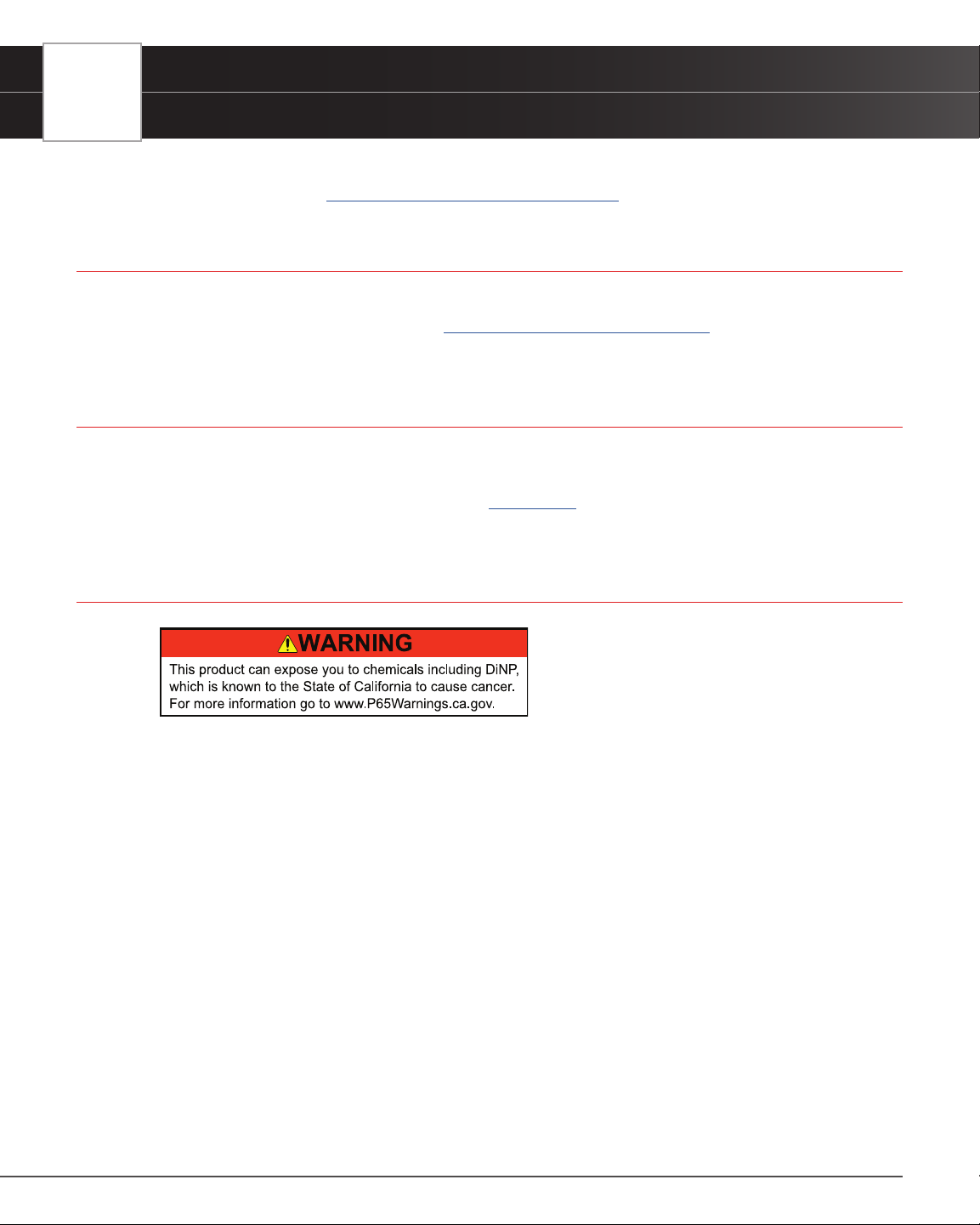
CALIFORNIA PRODUCT WARNINGS

SAFETY PRECAUTIONS
Safety First!
3
SAFETY PRECAUTIONS
SAFETY FIRST!
It is important that every user utilizing this product read all instructions and warnings included within this manual
to ensure your safety, the safety of others, and to prevent damage to this product & vehicles being diagnosed and
repaired. This manual describes common test procedures used by experienced service technicians. It is inferred that
the user has a good understanding of vehicle systems before using this product.
Many test procedures require precautions to avoid accidents that can result in personal injury, and/or damage to
your vehicle or test equipment. At a minimum, the following safety standards should be followed whenever using this
product, or whenever working on a vehicle.
When an engine is running, it produces carbon monoxide, a toxic and poisonous gas. To
prevent serious injury or death from carbon monoxide poisoning, operate the vehicle ONLY in
a well-ventilated area.
To protect your eyes from propelled objects as well as hot or caustic liquids, always wear
approved safety eye protection.
When an engine is running, many parts (such as the coolant fan, pulleys, fan belt etc.) turn at
high speed. To avoid serious injury, always be aware of moving parts. Keep a safe distance
from these parts as well as other potentially moving objects.
Engine parts become very hot when the engine is running. To prevent severe burns, avoid
contact with hot engine parts.
Before starting an engine for testing or troubleshooting, make sure the parking brake is
engaged. Put the transmission in park (for automatic transmission) or neutral (for manual
transmission). Block the drive wheels with suitable tire blocks.
Connecting or disconnecting test equipment when the ignition is ON can damage test equipment
and the vehicle’s electronic components. Turn the ignition OFF before connecting the tablet
to or disconnecting the tablet from the vehicle’s Data Link Connector (DLC).
To prevent damage to the on-board computer when taking vehicle electrical measurements,
always use a digital multimeter with at least 10 Megohms of impedance.
Fuel and battery vapors are highly ammable. To prevent an explosion, keep all sparks, heated
items, and open ames away from the battery and fuel vapors. DO NOT SMOKE NEAR THE
VEHICLE DURING TESTING
Don’t wear loose clothing or jewelry when working on an engine. Loose clothing can
become caught in the fan, pulleys, belts, etc. Jewelry is highly conductive and can cause a
severe burn if it makes contact between a power source and ground.
4
SAFETY PRECAUTIONS
Safety Alert Icons
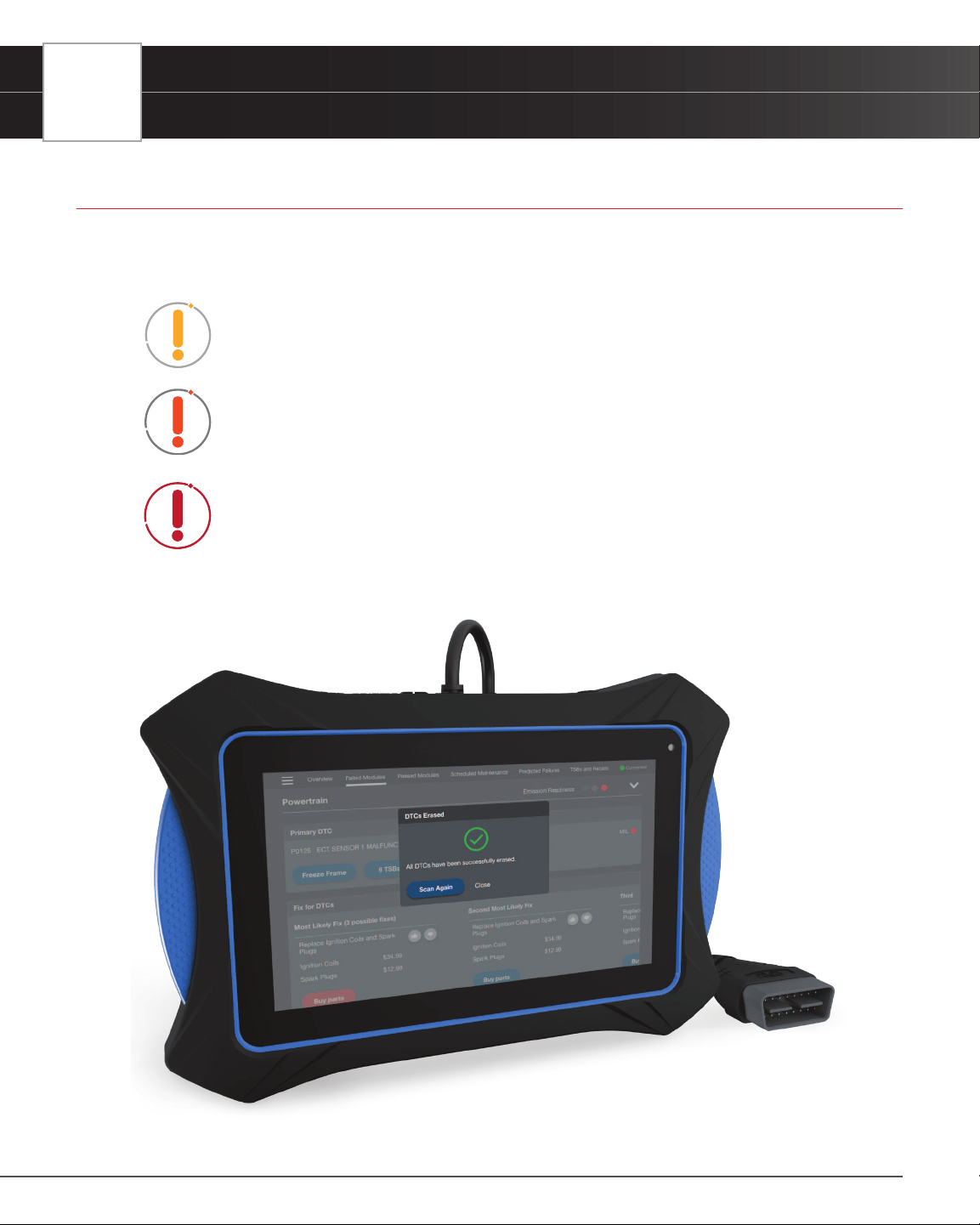
SAFETY ALERT ICONS
As you read this manual, color-coded icons are used throughout to identify safety alerts and warnings. These are
provided to help prevent serious injury to you, injury to bystanders, and damage to property or equipment. They are
characterized as follows:
Yellow Icon – Provides a ”NOTE:“ statement to offer special information
or tip on what is being instructed.
Orange Icon – Potential hazardous situation. Provides a “WARNING:“
statement on how to proceed to avoid serious injury to the user,
bystanders, and/or equipment.
Red Icon – Imminent hazardous situation. Provides an immediate
“DANGER:“ alert on what must be done to prevent serious injury or death
to the user or bystanders.
INTRODUCTION
Tablet Controls
5
INTRODUCTION
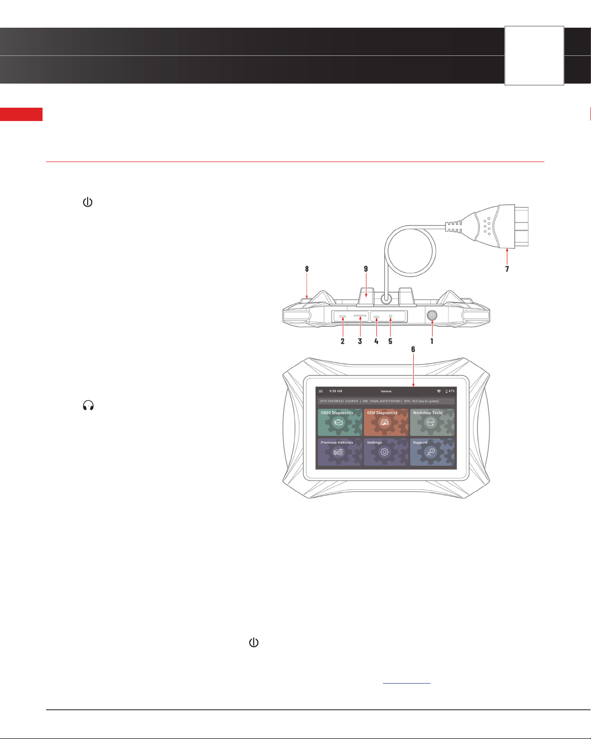
TABLET CONTROLS
See Figure 1 for the locations of items 1 through 9, below.
1. POWER Button - Turns the tablet “On”
and “Off.” When tablet is off, press and
hold for approximately 3 seconds to turn
on. When tablet is on, press and hold for
approximately 3 seconds to display the
“power down” options menu.
2. USB Charging Port – Supports charging of
the tablet battery using provided USB cable
and power adapter.
3. TF-Card Port – Supports installation of a TF
(expandable memory) card. Functionality is
currently disabled.
4. Mini HDMI Port – Supports connection of an
external HDMI (High-Denition Multimedia
Interface) compatible external display.
5.
Headphone Port – Supports connection
of external headphones. (Future expansion)
6. Display - 7-inch color LCD display shows
menus and sub-menus, test results, tablet
functions and vehicle status information.
7. DLC Cable - Connects the tablet to the
vehicle’s on-board Data Link Connector
(DLC).
8. Rear Kickstand – Lets you freely stand the
tablet on a solid surface.
9. Detachable VCI Connector – The detachable Vehicle Communication Interface (VCI) connector allows mobility
and exibility around the vehicle by detaching the tablet from the DLC cable and wirelessly connecting via Blue-
tooth
®
.
Power ON and Power OFF
To power ON the tablet:
1. With the tablet off, press and hold the
POWER button for approximately 3 seconds, then release.
n The screen displays the message “LOADING” while the software loads.
n When the software has been loaded, the Home Page displays. [See page 8]
Figure 1: Tablet Controls

6
INTRODUCTION
Initial Tablet Setup
2. If the tablet is connected to a vehicle, the message “Retrieving vehicle information…” automatically shows
while the tablet establishes communication with the vehicle.
To restart or power OFF the tablet:
3. With the tablet on, press and hold the
POWER button for approximately 3 seconds.
n The “power down” options menu displays at the right side of the screen.
4. To restart the tablet:
n Tap the
Restart icon.
n The screen displays the message “LOADING” while the software loads.
n The Home screen displays once the software is loaded. [See page 8]
n If the tablet is connected to a vehicle, the message “Retrieving vehicle information…” displays
while the tablet establishes communication with the vehicle.
5. To power off the tablet:
n Tap the
POWER icon.
n The tablet powers down and turns off.
INITIAL TABLET SETUP
Follow these steps to setup the tablet for the rst time.
1. Charge Tool – use the included charging cable to completely charge your tool before conducting your
rst scan.
2. Power On – Once fully charged, press and hold the
POWER button for approximately 3 seconds.
3. Create Your Account – Allows complete access to all of the tablet’s powerful features. [
See page 7]
4. Check for Updates – We’re continuously making free software, data, and rmware updates. It is important
to keep your tablet up to date to ensure its best performance. Please follow the steps to check and
automatically update your tablet under SETTINGS / Version Information. [
See page 86]
5. Enjoy your INNOVA
®
Smart Diagnostic System!
Have questions? We’re here to help:
n Live Chat: www.innova.com
n Email Us: [email protected]
n Call Us: 800-544-4124 (Monday through Friday, 6am - 6pm PST)
INTRODUCTION
Create Your Account
7
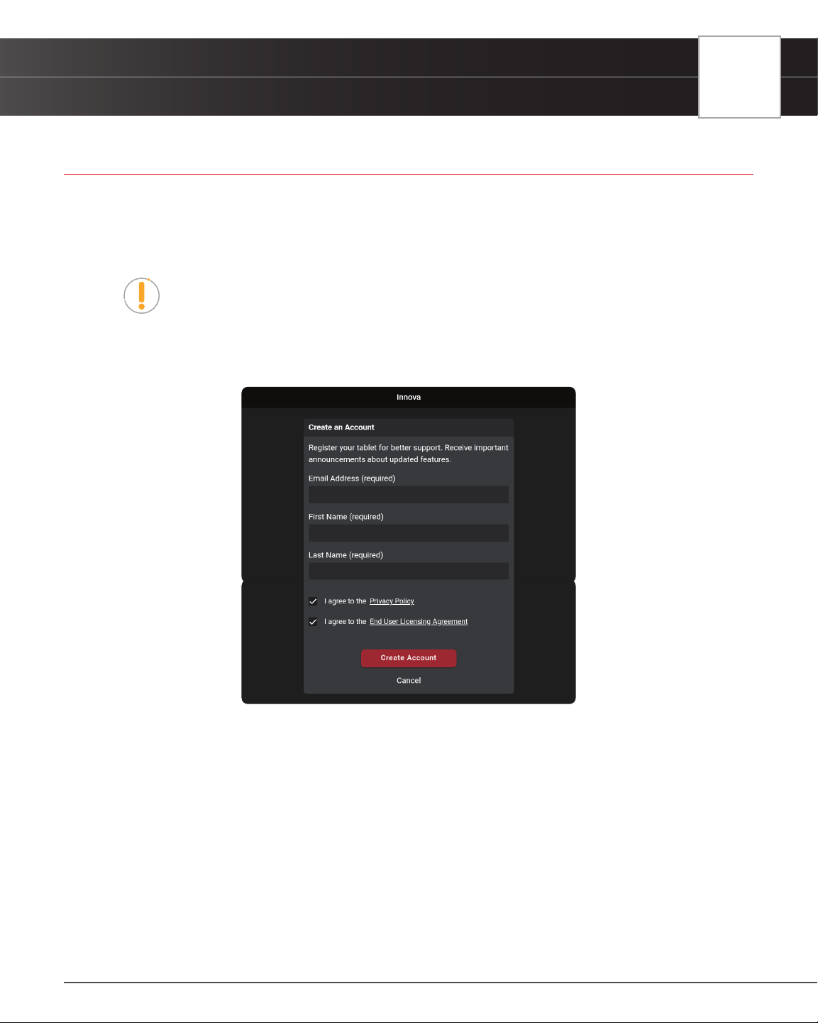
CREATE YOUR ACCOUNT
The rst time you power on your tablet, you will be asked to create a RepairSolutionsPRO™ account. Although it is
optional, having a personal account will help keep your tablet updated with the latest updates and future enhancements.
Plus, get access to our extensive database of veried DTC xes – curated by our network of ASE Certied master
technicians.
Note: Please make sure your tablet is properly connected to your wireless network
before registering. A “No Internet Connection” displays if the device is not connected
to the Internet. Follow the prompts to complete your connection.
1. Complete the displayed Create an Account form with your name, email address, your desired password, and
other personal information.
2. Agree to the terms and tap on the Create Account button at the bottom of the form.
3. Continue by selecting your tablet preferences:
Date and Time
Wi-Fi Connection
Preferred Units
Idle Time
Volume Level
Brightness Level
Theme Preference
4. Tap the Continue button to conrm your selections.
8
INTRODUCTION
The Home Screen
*** Please reference the Settings tab to make additional account changes and edits. [See page 78]
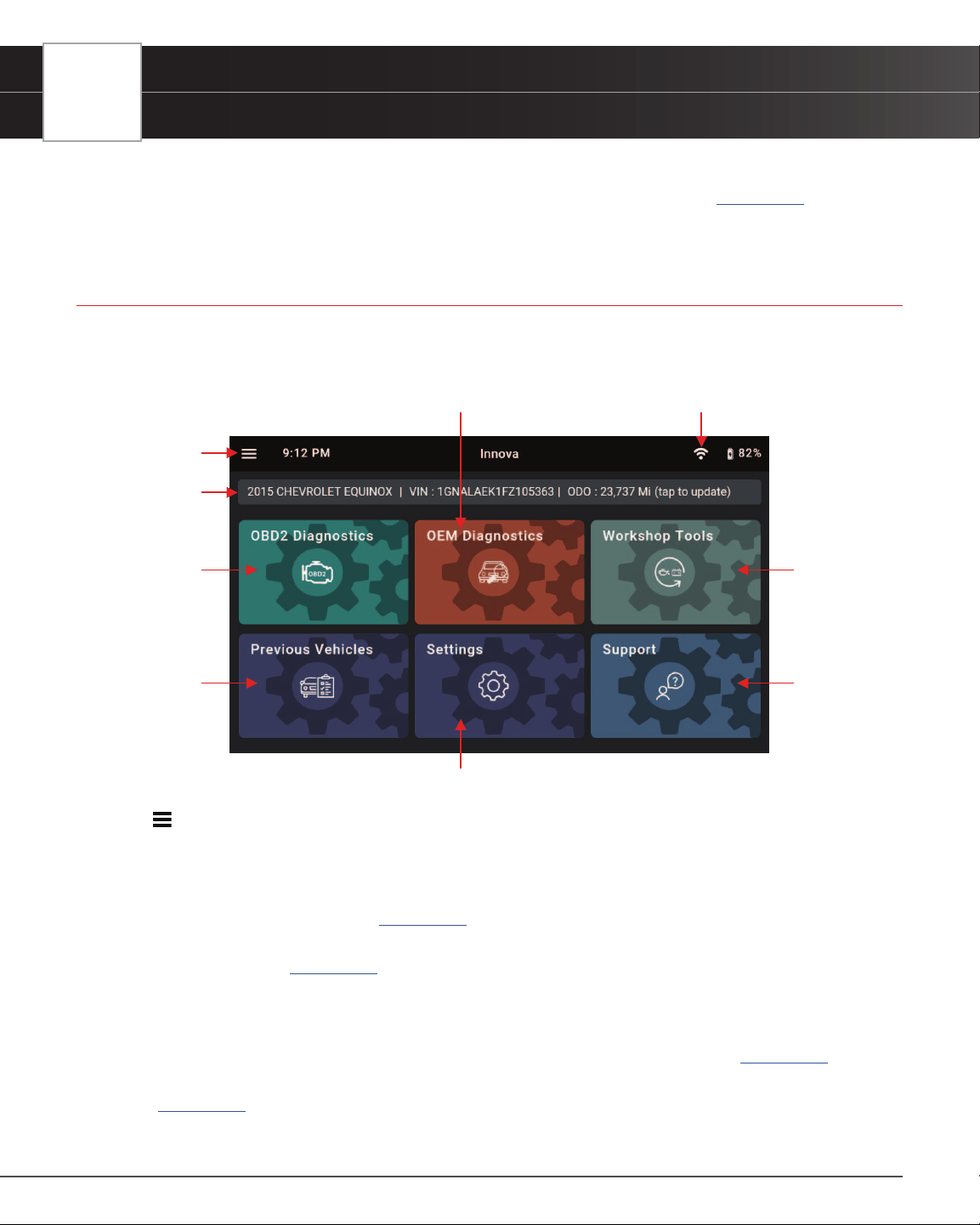
THE HOME SCREEN
The Home screen provides access to all the tablet’s primary functions. See Figure 2 for the explanation of items 1
through 9, below.
1. Main Menu – Quick access to Home, Previous Vehicle, Support, Settings and Updates (when available).
2. Vehicle Info Bar – When connected to a vehicle, dialog displays vehicle’s make, model, year, VIN, and
current mileage (ODO).
3. OBD2 Diagnostics Tab – Use to perform OBD2 scans, view & record Live Data, create a RepairSolutionsPRO
Report, and Erase OBD2 DTCs. [
See page 15]
4. Previous Vehicles Tab – Access and view reports for all previously tested vehicles, including pre-recorded
Live Data streams. [
See page 75]
5. OEM Diagnostics Tab – Provides enhanced OEM level diagnostics that are not available over generic
OBD2. Access ABS, Airbag, Transmission, Tire Pressure, Battery, and many Body control modules to view
and erase their DTCs. Perform bi-directional tests on fuel pump, injectors, ignition coils, and much more.
Plus, get access to hundreds of additional parameters that you can view in real-time. [
See page 30]
6. Settings Tab – Setup your tablet’s settings, including Wi-Fi, update software, and other personal settings.
[
See page 78]
7. Workshop Tools Tab – Perform several OEM service reset procedures, including: Oil Maintenance
1
2
3
4
5
6
7
8
Figure 2: The Home Screen
9

INTRODUCTION
Technical Specications
9
Reset, Battery Reset, Electronic Parking Brake Reset, Steering Angle Sensor (SAS) Reset, ABS Bleeding,
Battery/Alternator Test, and EV/HEV/PHEV Battery Health. Access dealership level re-learn procedures to
complete repairs or maintenance and much more. [
See page 41]
8. Support Tab – Access the tablet’s Tool Library for DTC and tool icon denitions; connect with Innova’s ASE
Certied Technical Team for support. [
See page 89]
9.
Wi-Fi Icon - Tap to access and edit the tablet’s Wi-Fi settings [See page 81]
TECHNICAL SPECIFICATIONS
The following table provides the tablet’s current technical specications*:
Display Type
7” Touch Panel / 1024x600 pixels
J1962 DLC Cable
6-foot Detachable 16-pin OBDII Compliant Connector
Detachable Vehicle
Communication Interface (VCI)
with Bluetooth
®
Connectivity
Maximum communication range of 30 feet.
Operating System
Proprietary user interface running on Android 9.0
Battery
Built-in 6000mAH rechargeable battery / 6-hour life
Wi-Fi
802.11b/g/n
Operating Temperature
23ºF to 113ºF (-5ºC to 45ºC)
Memory
16GB Memory for Report and Image Storage
I/O Interface
Micro USB2.0, HDMI Port, TF Card Slot, Headphone,
and USB Charging Port.
Tablet Case
Rugged ABS Shock & Drop Resistant
Included Accessories
Molded Storage Case, Power Supply, Quick Start
Guide
*Manufacturer reserves the right to change technical specications at any time.
10
INTRODUCTION
The RepairSolutionsPRO™ App
THE RepairSolutionsPRO™ APP
Innova’s RepairSolutionsPRO™ (RSPRO) app is a web-based service
created to assist professional technicians simplify and augment their vehicle
diagnostic process.
In essence, it helps you decode the diagnostic data collected by your
INNOVA
®
OBD2 Tablet to arrive at a most likely x. At its core, the app uses a database of millions of real-world veried
xes–collected over the last 25 years by ASE Master Technicians across the U.S.– that is cross-referenced to your
specic vehicle’s problem to instantly arrive at a veried x. Think of it as a second opinion from your most trusted
peers to help you diagnose and repair more vehicles.
THE RSPRO APP OFFERS…
n Veried Fixes – Find the most likely xes reported and veried by ASE Technicians for the
retrieved DTCs. Plus, quickly purchase the exact parts you need right from the app.
n Predicted Repairs – With millions of veried repair solutions, get a statistical probability of what
repairs the vehicle may need within the next 12 months.
n TSBs & Recalls – Learn if there are any special NHTSA safety recalls or Technical Service
Bulletins (TSBs) issued by the vehicle’s manufacturer.
n Upcoming Maintenance – View the vehicle manufacturer’s recommended maintenance
intervals. Plus, conveniently order the correct maintenance parts right from the app.
n And much more...
HARDWARE REQUIREMENTS
n Innova OBD2 Tablet with Bluetooth/Wi-Fi connectivity.
n Android or iOS Mobile Device.
DOWNLOAD THE RSPRO APP
n Available for Apple iOS & Android Devices (Scan QR Code)
USING THE RepairSolutionsPRO APP
1. Retrieve your vehicle’s diagnostic data. [See page 15]
2. Download and install the RSPRO app (see above).
3. Launch the app and log in to your account.
n If you have not yet established an account, you must register for a FREE account before
proceeding.

INTRODUCTION
The RepairSolutionsPRO™ App
11
4. Follow the screen prompts to pair your INNOVA Tablet.
━ Turn On Bluetooth
®
on your mobile device.
━ Turn the tablet On.
━ Be sure your mobile device is connected to an available Wi-Fi network.
n Begin the pairing process by selecting your handheld tablet from the list.
NOTE: The RSPRO app can only store up to two Wi-Fi congurations.
5. Once paired, the data from your tablet is automatically transferred to the app to create a report.
NOTE: If the data does not automatically transfer, simply keep the app and tablet
paired and scan your vehicle again.
NOTE: Once the tablet is paired and registered with the RepairSolutionsPRO App,
the tablet must be connected to a Wi-Fi network by using the RepairSolutionsPRO
App or by going to Settings / Wi-Fi Setting tab on the tablet in order to access
functions such as viewing Fix for DTCs, OBD2 Report, and Vehicle Inspection.
12
GETTING STARTED
Connecting the Tablet
GETTING STARTED
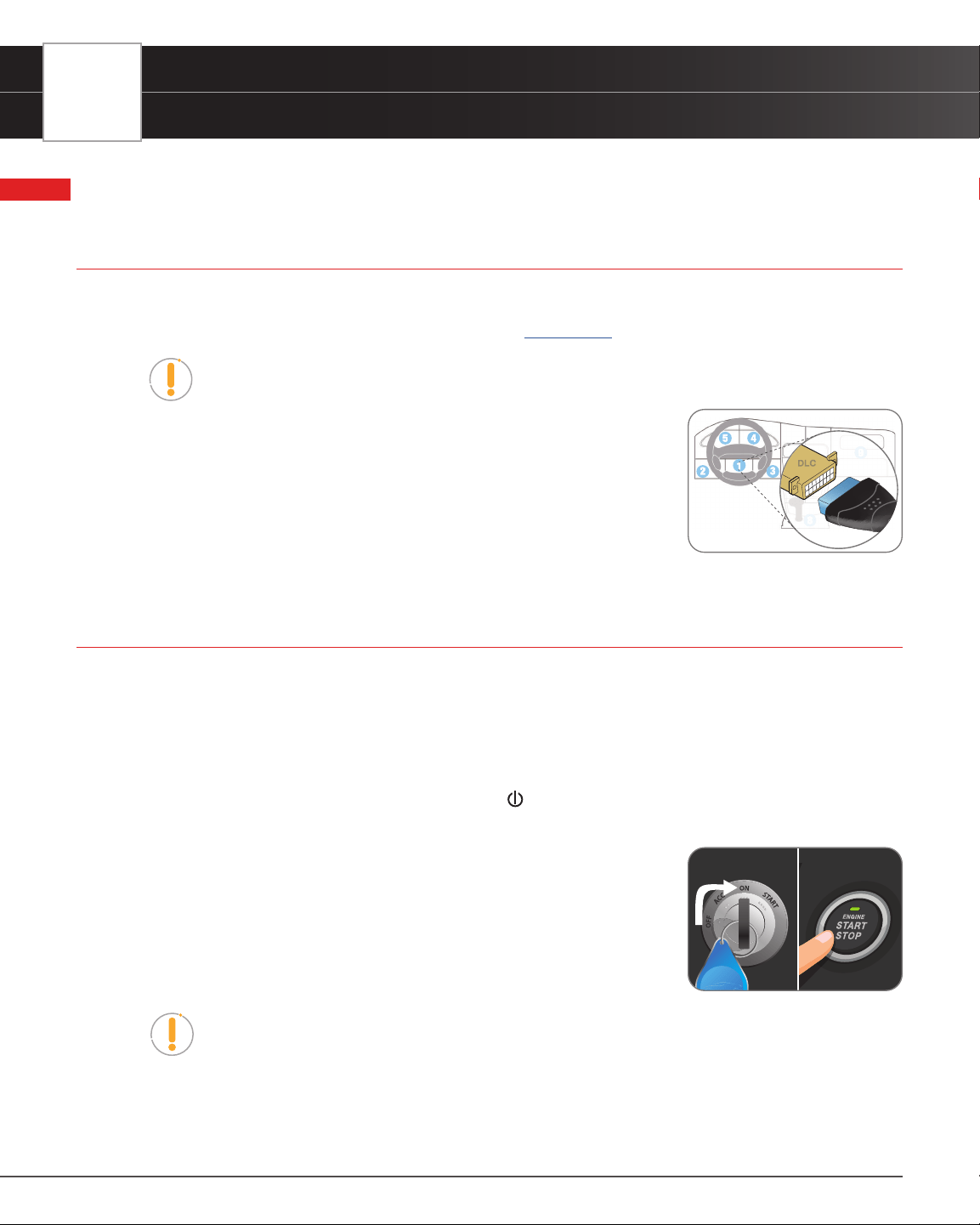
CONNECTING THE TABLET
1. Turn the vehicle’s ignition OFF.
2. Locate the vehicle’s 16-pin Data Link Connector (DLC). [
See page 84]
NOTE: Some DLCs have a plastic cover that must be
removed before connecting the Scan Tool.
3. Connect the tablet to the vehicle’s DLC. The cable connector is
keyed and will only t one way.
n If you have problems connecting the cable to the DLC, rotate the
connector 180°.
n If you still have problems, check the DLC on the vehicle and on the
tablet.
AUTOLINK CONNECTION
The tablet features an “AutoLink Connection” function, which automatically retrieves vehicle information upon
plugging the tablet into the vehicle’s Data Link Connector (DLC) port.
Using the AutoLink Function
1. Verify that the tablet is connected as indicated above (Connecting the Tablet).
2. If the tablet is off, power ON the tablet by pushing the
POWER button for 3 seconds.
3. Turn the ignition ON. DO NOT start the engine.
n Tablet begins communicating and displays “Retrieving Vehicle
Information...”
n If an “Information” dialog appears, follow the on-screen instructions to
establish a connection.
4. Once complete, tablet displays the vehicle’s Year, Make, Model, VIN, and
mileage on the Vehicle Info Tab.
NOTE: With certain vehicles, you may be required to manually input some of the
vehicle’s information. This may include the vehicle’s Year, Make, Model, Trim, Body
Code, Engine; vehicle’s VIN; and/or the vehicle’s mileage.
Providing Vehicle’s VIN Information
1. A dialog appears requesting a Vehicle Identication Number (VIN)
NO Brake Pedal
Tap Button 2 Times
GETTING STARTED
Scanning a Vehicle
13
2. Tap the dialog window and enter the vehicle’s 17-digit VIN number
n The Submit button becomes “active” once all 17-digits are entered
3. Tap the Submit button
n An error dialog will display if the VIN is unable to be decoded. Re-enter VIN.
n If you are still unable to decode the VIN, tap Select Vehicle (see steps below).
Providing Vehicle Selection Information
1. A dialog appears requesting Vehicle Selection
2. Tap on each of the available entries (Year, Make, Model, Trim, Body Code, Engine)
n A grayed-out selection means that an entry is not available or not necessary for this vehicle.
3. Make a selection under each option.
4. Tap Continue to save your selections and return to the Home screen.
5. Tap Cancel to exit without selecting and return to the Home screen.
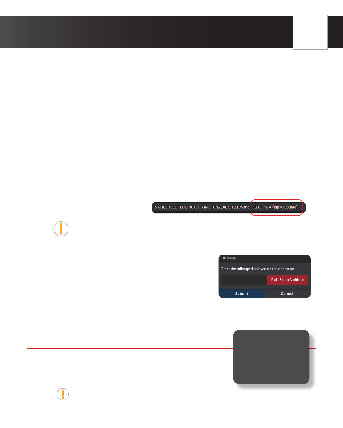
Providing Vehicle’s Mileage
If mileage is missing, the Vehicle Info Bar will
show “ODO: N/A (tap to update)”.
NOTE: Please be aware that correct mileage is necessary to generate accurate
diagnostic reports.
1. Tap on the Vehicle Info Bar “(tap to update)”.
2. Tap Pull From Vehicle to auto retrieve the vehicle’s stored mileage.
n A progress bar appears “One moment please...”
3. If successful, the screen returns to the Home page and displays
mileage in the Vehicle Info Bar.
4. If unsuccessful, an error dialog appears
n Tap on the entry box and enter mileage.
n Tap Submit to conrm entry and return to the Home page.
SCANNING A VEHICLE
Never replace a part based only on the DTC denition. Each DTC has a set of
testing procedures, instructions and ow charts that must be followed to conrm
the location of the problem. Always refer to the vehicle’s service manual for
detailed testing instructions.
NOTE: Check your vehicle thoroughly before performing any test.
Retrieving and using
Diagnostic Trouble Codes
(DTCs) for troubleshooting
vehicle operation is only
one part of an overall
diagnostic strategy.

OBD2 DIAGNOSTICS
Performing a Scan – OBD2 Diagnostics
15
OBD2 DIAGNOSTICS
The OBD2 Diagnostics function allows you to perform OBD2 scans, view
& record Live Data, create a RepairSolutionsPRO
Report, and Erase OBD2
DTCs.
PERFORMING A SCAN – OBD2 Diagnostics
1. Follow the AutoLink Connection steps. [See page 12]
2. Tap OBD2 Diagnostics.
n The tablet automatically starts a check of the vehicle’s computer to determine which
communication protocol it is using. When the tablet identies the computer’s communication
protocol, a communication link is established.
NOTE: A PROTOCOL is a set of rules and procedures for regulating data
transmission between computers, and between testing equipment and computers.
As of this writing, ve different types of protocols (ISO 9141, Keyword 2000, J1850
PWM, J1850 VPW and CAN) are in use by vehicle manufacturers.
n If the Scan Tool fails to link to the vehicle’s computer, a “Scan Failed” message shows.
━ Ensure the vehicle is OBD2 compliant–check vehicle emission control information (VECI)
label located in the vehicle’s engine compartment.
━ Verify the connection at the DLC, and verify the ignition is ON.
━ Turn the ignition OFF, wait 5 seconds, then back ON to reset the computer.
━ Tap Try Again to try again, or tap Cancel to return to the Home Page.
3. A progress dialog displays while the tablet retrieves any Diagnostic Trouble Codes, Monitor Status and Freeze
Frame Data from the vehicle’s computer memory.
4. When the retrieval process is complete, the OBD2 Diagnostics screen displays with the scan results.
VIEWING SCAN RESULTS – OBD2
Diagnostics
Scan results are shown immediately
following completion of a scan; and can
also be viewed later using the PREVIOUS
VEHICLE function available through the
Home page [
See page 75].
16
OBD2 DIAGNOSTICS
Viewing Scan Results – OBD2 Diagnostics
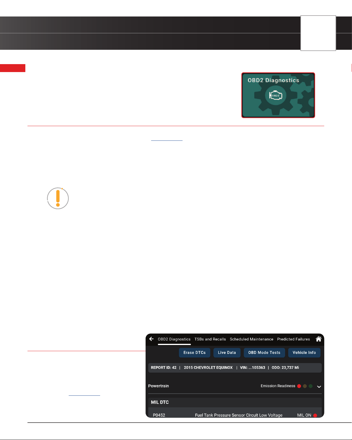
Scan results are shown in a multi-page display, which includes OBD2 Diagnostics, TSBs and Recalls, Scheduled
Maintenance, and Predicted Failures.
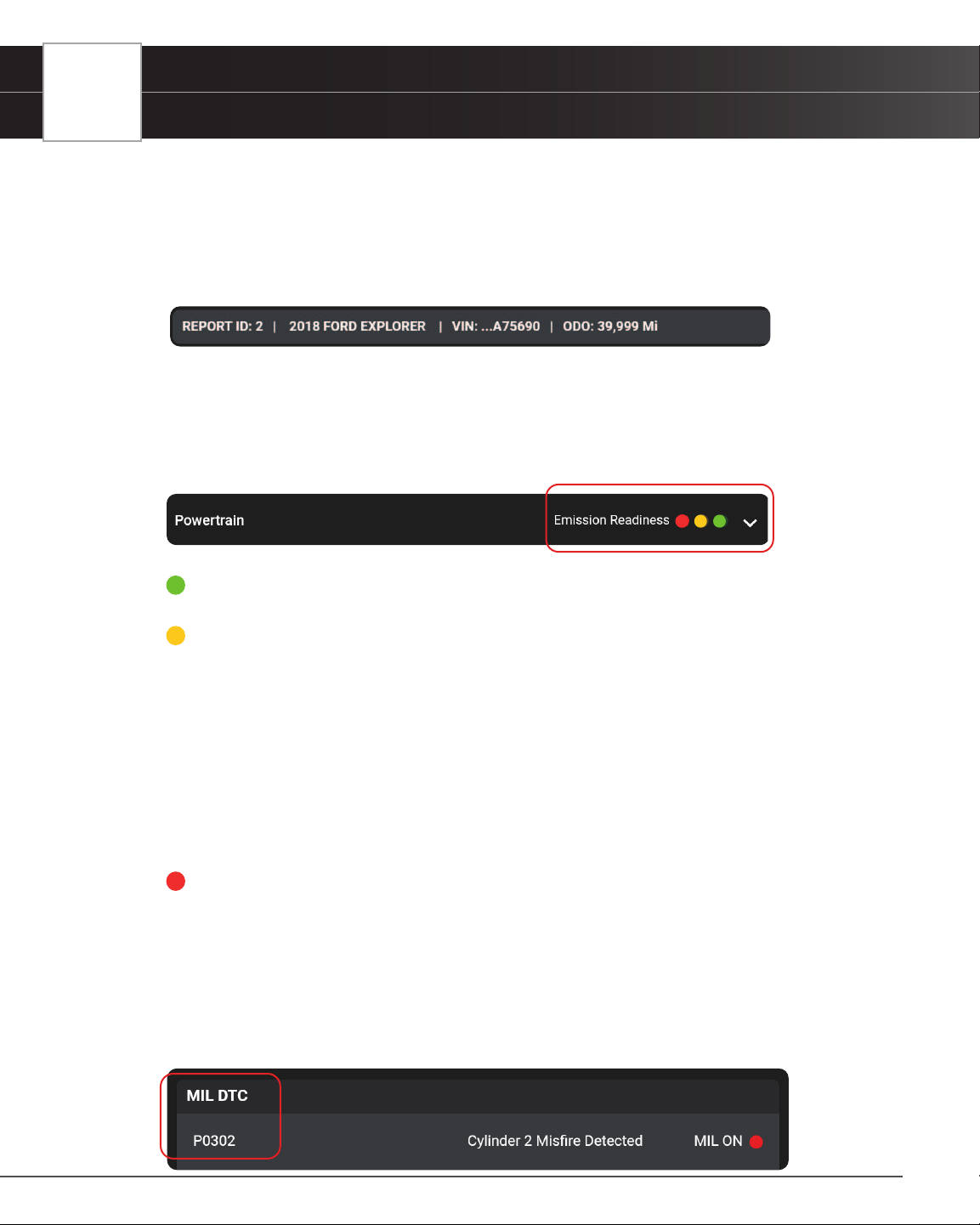
Each report begins with a vehicle information bar that includes a Report ID, the vehicle’s description (year/make/
model), the last six digits of the Vehicle Identication Number (VIN) and the odometer reading (ODO) at the time
the scan was performed.
EMISSIONS READINESS – Interpreting Results
Indicates whether the vehicle is ready for an Emissions Test (Smog Check) through a “trafc light” type display. When
viewing the Emission Readiness eld, use the following denitions to identify the vehicle’s Emissions Test readiness
status:
n Green - Indicates all engine systems are operating normally. The vehicle is ready for an
Emissions Test (Smog Check), and there is a good possibility it can be certied.
n Yellow – Indicates one of the following two conditions is present:
━ A “Pending” Diagnostic Trouble Code is present. It is possible the vehicle can be tested
for emissions and certied. Many areas (states / countries) allow an Emissions Test to be
performed if the only code present is a “PENDING” code.
━ One or more monitors “Have Not Run” their diagnostic testing. The issue of the vehicle
being ready for an Emissions Test will depend on the emissions regulations and laws of
your local area.
━ Some areas require that all Monitors indicate a “Has Run” status before an Emissions Test
(Smog Check) can be performed. Other areas only require that some, but not all, Monitors
indicate a “Has Run” status before an Emissions Test can be performed.
n Red - Indicates there is a problem with one or more of the vehicle’s systems, and Diagnostic
Trouble Code(s) (DTCs) are present. The vehicle is not ready for an Emissions Test. The
problem(s) that caused the DTCs to set must be repaired before an Emissions Test can be
performed.
MIL DTC Code
This is the code that has commanded the vehicle’s Malfunction Indicator Lamp (MIL) “on,” and is the code for which
Freeze Frame data stored. This eld includes the DTC number, description, and MIL status (ON or OFF).
OBD2 DIAGNOSTICS
Viewing Scan Results – OBD2 Diagnostics
17
n In OBD2 systems, when an emissions-related engine malfunction occurs that causes a DTC
to set, a record or snapshot of engine conditions at the time that the malfunction occurred is
also saved in the vehicle’s computer memory. The record saved is called Freeze Frame data.
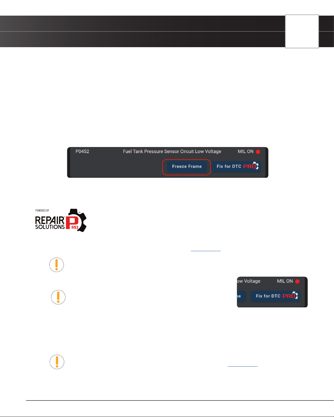
Viewing Freeze Frame Data
Under Freeze Frame, saved engine conditions can include, but are not limited to engine speed, open or closed
loop operation, fuel system commands, coolant temperature, calculated load value, fuel pressure, vehicle speed,
air ow rate, and intake manifold pressure. These values are typically used to further diagnose and pinpoint the
issue.
n Tap the Freeze Frame button to view the captured results.
FIX FOR DTCs (RSPRO)
Innova’s RepairSolutionsPRO™ (RSPRO) reports offer a x, which is cross referenced for
accuracy against a database of millions of veried xes. It is real-world data that has been
collected for over 25 years by Innova’s network of ASE Master Technicians across the U.S.
If available, it includes the most likely x(es) for the MIL DTC and the parts required to repair it. If not, it only shows the
OBD2 Report, which its data can be uploaded to the RSPRO app. [
See page 10]
NOTE: Certain elds and pages require that you create a RepairSolutionsPRO report
to access, download and display the associated “enhanced” data…
1. Tap the Fix for DTC in the OBD2 Diagnostics screen.
NOTE: Verify the tablet is registered to the RepairSolutionsPRO
App.
n If you haven’t registered for the RSPRO app yet or you are logged out, a screen displays asking
to either log it to your account, or create an account.
2. With the tablet paired and registered with the RepairSolutionsPRO App.
n The tablet also veries if it’s connected to a Wi-Fi network.
NOTE: The tablet can be connected to a Wi-Fi network by using the
RepairSolutionsPRO app, or by using the Settings tab on the tablet. [
See page 81]
3. The tablet’s screen displays Fix for DTCs, and includes:
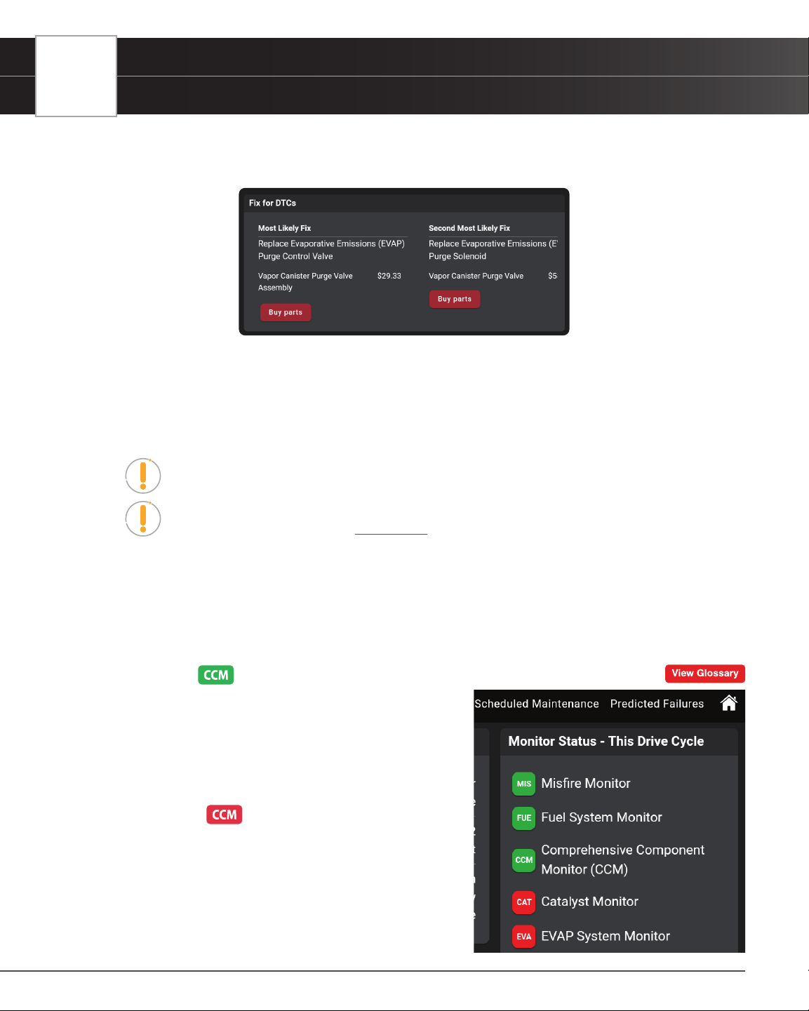
18
OBD2 DIAGNOSTICS
Viewing Scan Results – OBD2 Diagnostics
n Most Likely Component/System Cause for the DTC.
━ Includes recommended parts, cost, and a Buy parts button.
n Second Most Likely Component/System Cause for the DTC.
n Third Most Likely Component/System Cause for the DTC.
━ Swipe right to view other likely xes.
n Other Most Likely Component/System Cause for the DTC.
NOTE: If a Fix is not available for DTC, an advisory message displays.
NOTE: The Buy Parts button can be activated or disabled in the Settings tab under
the RepairSolutionsPRO section. [
See page 81]
MONITOR STATUS
Shows the current status for all Monitors supported by the vehicle. Available monitors are listed and identied as
follows (The CCM - Comprehensive Component Monitor is being used as an example.):
Green Solid Icon =
Description: This icon indicates the monitor has completed both
Since DTCs Cleared (KOEO) and This Driving Cycle testing
(KOER).
Tips: The monitor has met all conditions required to complete
self-diagnosis and testing of the assigned system.
Red Flashing Icon =
Description: This icon indicates that the monitor has not
completed testing Since DTCs Cleared (KOEO).
Tips: The monitor has not met all conditions required to complete
self-diagnosis and testing of the assigned system. A drive cycle
may need to be performed to complete the testing.
OBD2 DIAGNOSTICS
Viewing Scan Results – OBD2 Diagnostics
19
Green/Gray Flashing Icon =
Description: This icon indicates that the monitor has not completed testing This Driving Cycle (KOER).
Tips: The monitor has not met all conditions required to complete self-diagnosis and testing of the assigned
system. A drive cycle may need to be performed to complete the testing.
Red/Gray Flashing Icon =
Description: This icon indicates that the monitor has been disabled This Driving Cycle (KOER).
Tips: The monitor is unable to complete self-diagnosis and testing of the assigned system. The monitor is
disabled for this driving cycle, check for failed OBD Monitor Test and refer to the service information before
continuing.
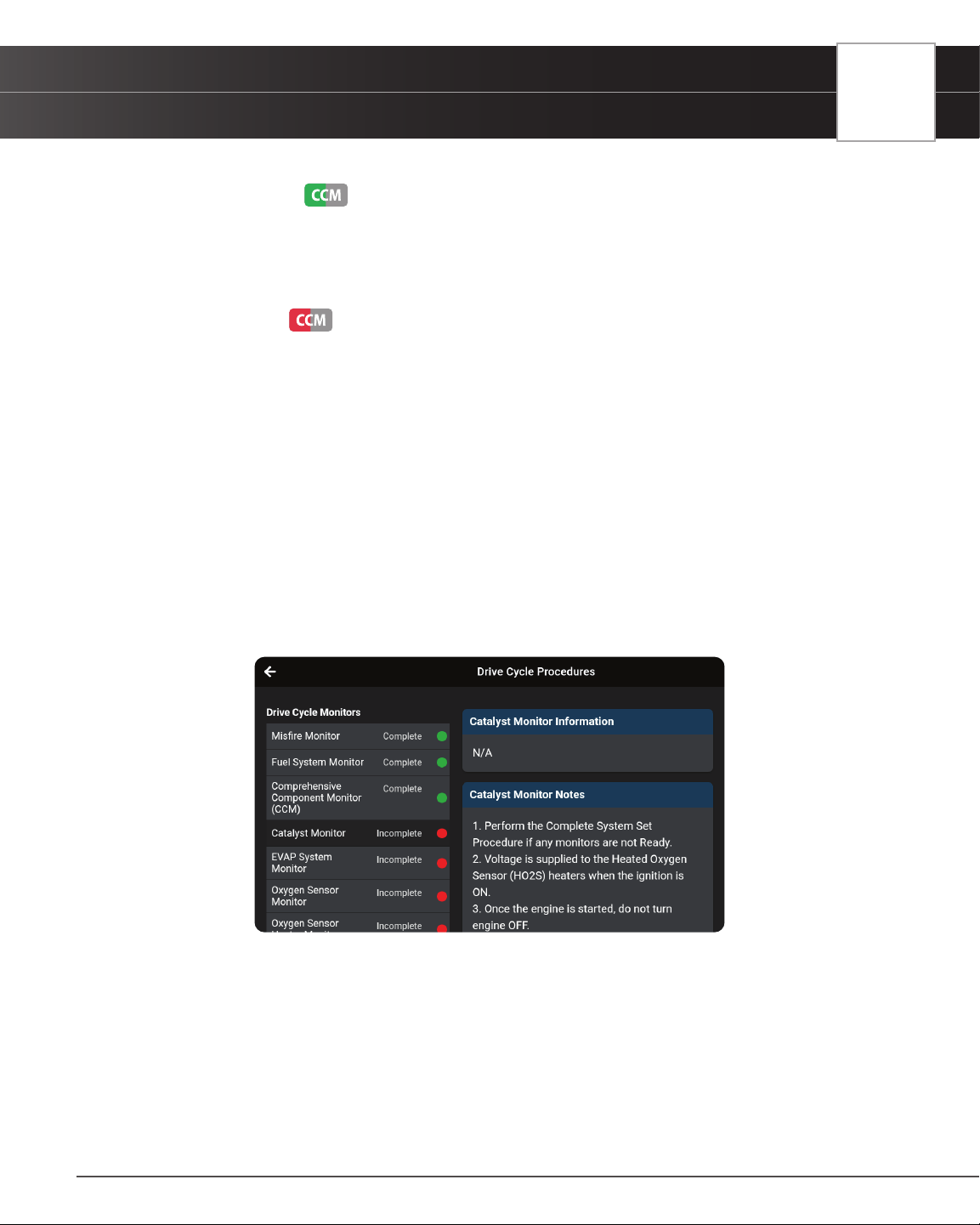
Viewing Drive Cycle Procedures
A Drive Cycle for a monitor requires that the vehicle is driven in such a way that all the required “Enabling Criteria”
for the monitor to run and complete its diagnostic testing are met. You can use the tablet to view the Drive Cycle
procedures for a selected Monitor.
1. From the Monitor Status eld on the OBD2 Diagnostic page, tap the View Drive Cycles button.
n The Drive Cycle Procedures page displays.
n The Drive Cycle Monitors column on the left lists the monitors supported by the vehicle; and
shows the status of each monitor at the time the scan was run (Complete, Incomplete, or
Disable).
n The right column of the page shows the Drive Cycle procedure for the currently selected
monitor.
2. Tap a monitor name to view the Drive Cycle procedure for the selected monitor.
n The page refreshes to display Monitor information and the Drive Cycle procedure for the
selected monitor.
20
OBD2 DIAGNOSTICS
Additional Testing Utilities
3. Follow the provided steps to perform and complete the monitor’s “Enabling Criteria”.
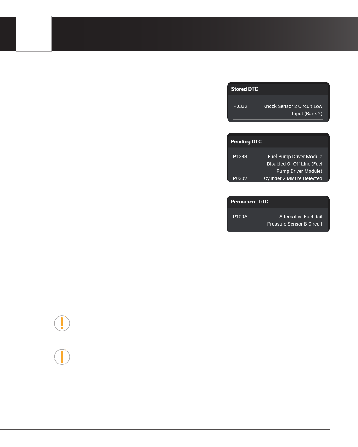
STORED DTC
Shows all “stored” powertrain DTCs for the vehicle. Each entry in
the list includes the DTC number and description.
PENDING DTC
Shows all “pending” powertrain DTCs for the vehicle. Each entry in
the list includes the DTC number and description.
PERMANENT DTC
Shows all “permanent” powertrain DTCs for the vehicle. Each entry
in the list includes the DTC number and description.
ADDITIONAL TESTING UTILITIES
The following utilities are also included under the OBD2 DIAGNOSTICS scan results.
ERASING OBD2 DTCS
NOTE: When the Erase function is used to erase DTCs from the vehicle’s on-board
computer, “Freeze Frame” data and manufacturer-specic-enhanced data are also
erased. “Permanent” DTCs ARE NOT erased by the Erase function.
NOTE: When DTCs are erased, the I/M Readiness Monitor Status program resets
the status of all Monitors to a not run condition. To set all Monitors to a COMPLETE
status, an OBD2 Drive Cycle must be performed.
Erase DTCs from the vehicle’s computer memory as follows:
1. Perform the AutoLink Connection steps. [
See page 12]
n If the tablet is already connected and linked to the vehicle’s computer, proceed directly to Step
2.
OBD2 DIAGNOSTICS
Additional Testing Utilities
21
n Ensure that the ignition is in the Key ON, Engine OFF position
2. Tap the Erase DTCs button at the top of the OBD2 Diagnostic results page.
n The tablet displays an attention message conrming deletion.
n If you want to proceed, tap Erase DTCs to continue.
n If you do not want to proceed, choose Cancel to exit the erase procedure.
3. By selecting to Erase DTCs, a “One moment please…” progress dialog displays during the erase process.
n If the erase was successful, a conrmation message shows.
n After 3 seconds, the tablet automatically re-scans the vehicle to conrm DTC deletion.
4. If the erase was not successful, an advisory dialog displays indicating to either:
n Place the vehicle in the Key ON, Engine OFF position (OR)
n Place the vehicle in park or neutral; set the parking brake; and start the engine.
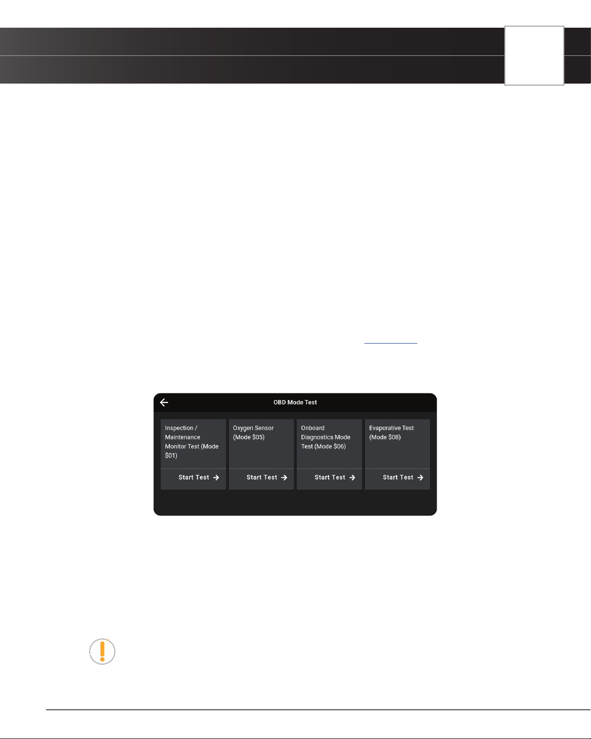
OBD MODE TESTS
OBD mode tests are accessed from the OBD2 Diagnostic results page. [See page 15]
1. Tap the OBD Mode Test button.
2. The OBD Mode Test screen is displayed with the following selections:
n Inspection/Maintenance Monitor Test ($01) – Lets you view the Drive Cycle Procedures for all
monitors supports by the vehicle.
n Oxygen Sensor (Mode $05) – Retrieves and displays O2 sensor monitor test results from your
vehicle’s on-board computer.
n Onboard Diagnostics Mode Test (Mode $06) – Retrieves test results for emission-related
powertrain components and systems that are not continuously monitored.
n Evaporative Test (Mode $08) – Performs a leak test for the vehicle’s EVAP system.
NOTE: In cases where a function is not supported by the vehicle under test, the
unsupported function is “grayed out,” and cannot be selected.
22
OBD2 DIAGNOSTICS
Additional Testing Utilities
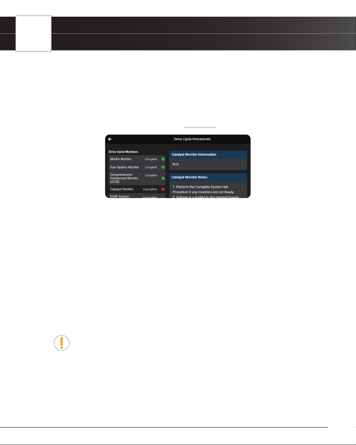
Inspection/Maintenance Monitor Test (Mode $01)
The Inspection/Maintenance Monitor Test ($01) lets you view the Drive Cycle Procedures for all monitors
supported by the vehicle. A Drive Cycle for a monitor requires that the vehicle is driven in such a way that all the
required “Enabling Criteria” for the monitor to run and complete its diagnostic testing are met. You can use the
tablet to view the Drive Cycle procedures for a selected Monitor.
1. From the OBD Mode Test screen, tap Inspection/Maintenance Monitor Test ($01).
n The Drive Cycle Procedures page displays. [See page 19]
n The Drive Cycle Monitors column on the left lists the monitors supported by the vehicle; and
shows the status of each monitor at the time the scan was run (Complete, Incomplete or
Disabled).
n The column on the right shows the Drive Cycle procedure for the currently selected monitor.
2. Tap a monitor name to view the Drive Cycle procedure for the selected monitor.
n The page refreshes to display the Drive Cycle procedure for the selected monitor.
Oxygen Sensor (Mode $05)
The Oxygen Sensor (Mode $05) lets you view the test results of the vehicle’s two or more O2 sensors. These
sensors are designed to help identify problems that can reduce fuel efciency or increase emissions. Each O2
sensor has a unique name that identies its location in the exhaust system – cylinder bank location (bank 1 or bank
2) and its location in relation to the catalytic converter (upstream or downstream). Please reference the vehicle’s
service manual for further information.
NOTE: Service Mode $05 is not supported in ISO 15765-4 (CAN) applications
– it includes the majority of 2008 and older vehicles. For CAN applications, the
functionality of Service Mode $05 was implemented in Service Mode $06.
1. From the OBD Mode Test screen, tap Oxygen Sensor (Mode $05).
n The Oxygen Sensor page displays.
2. Tap the X icon on the top right to return to the OBD Mode Test selection screen.

OBD2 DIAGNOSTICS
Additional Testing Utilities
23
Onboard Diagnostics Mode Test (Mode $06)
The Onboard Diagnostics Mode Test (Mode $06) retrieves and displays test results for emission-related powertrain
components and systems that are not continuously monitored. The tests available are determined by the vehicle
manufacturer.
NOTE: The tablet does not perform the OBD mode test. Instead, it retrieves results
from the most recently performed tests from the onboard computer’s memory.
1. From the OBD Mode Test screen, tap Onboard Diagnostics Mode Test (Mode $06).
2. When test results have been retrieved, the test results screen displays. The following information is provided
for each available test:
n Test ID number
n Component ID
n Test Value
n Min or Max test limit
NOTE: Only one test limit, either Min or
Max, is shown for any given test.
n Unit of measurement
n Status
NOTE: Status is calculated by the tablet by comparing the test Value against the
displayed test limit (either Min or Max). Status is shown as either Low, High or OK.
3. Tap the X icon to close the test results screen and return to the OBD Mode Test screen.
Evaporative Test (Mode $08)
The Evaporative Test (Mode $08) function lets you initiate a leak test for the vehicle’s EVAP system.
NOTE: The tablet does not perform the leak test, but signals to vehicle’s on-board
computer to initiate the test. The vehicle manufacturer determines the criteria
and method for stopping the test once it has been started. BEFORE using the
Evaporative Test function, refer to the vehicle’s service manual to determine the
procedures necessary to stop the test.
1. From the OBD Mode Test selection screen, tap Evaporative Test (Mode $08).
2. When the EVAP leak test has been initiated, a conrmation screen shows the message “OK.” Tap the X icon
to close the message and return to the OBD Mode Test screen.
NOTE: If the Evaporative Test (Mode $08) is not supported by the vehicle, an
advisory screen shows the message “Not support.”

24
OBD2 DIAGNOSTICS
Additional Testing Utilities
LIVE DATA MODE
The tablet allows you view and/or record “real-time” Live Data for further vehicle analysis. This information includes
values (volts, rpm, temperature, speed, etc.) and system status information (open loop, closed loop, fuel system status,
etc.) generated by the various vehicle sensors, switches, and actuators.
The real time (Live Data) vehicle operating information (values/status) that the computer supplies to the tablet for each
sensor, actuator, switch, etc. is called Parameter Identication Data (PID).
Each PID (sensor, actuator switch, status, etc.) has a set of operating characteristics and features (parameters) that
serve to identify it. The tablet displays this information for each sensor, actuator, switch, or status that is supported by
the vehicle under test.
DANGER: If the vehicle must be driven to perform a troubleshooting procedure,
ALWAYS have a second person help you. One person should drive the vehicle while
the other person observes the tablet data. Trying to drive and operate the tablet at
the same time is dangerous and could cause a serious injury to you and bystanders.
Viewing Live Data
1. Connect with the vehicle by following the steps for OBD2 DIAGNOSTICS / PERFORMING A SCAN. [See
page 15
]
2. While linked to the vehicle, start the engine.
3. Tap the Live Data button to place the tablet in Live Data mode.
n A progress dialog displays while the vehicle is scanned, and Live Data mode is activated.
n Tap Cancel to exit the procedure.
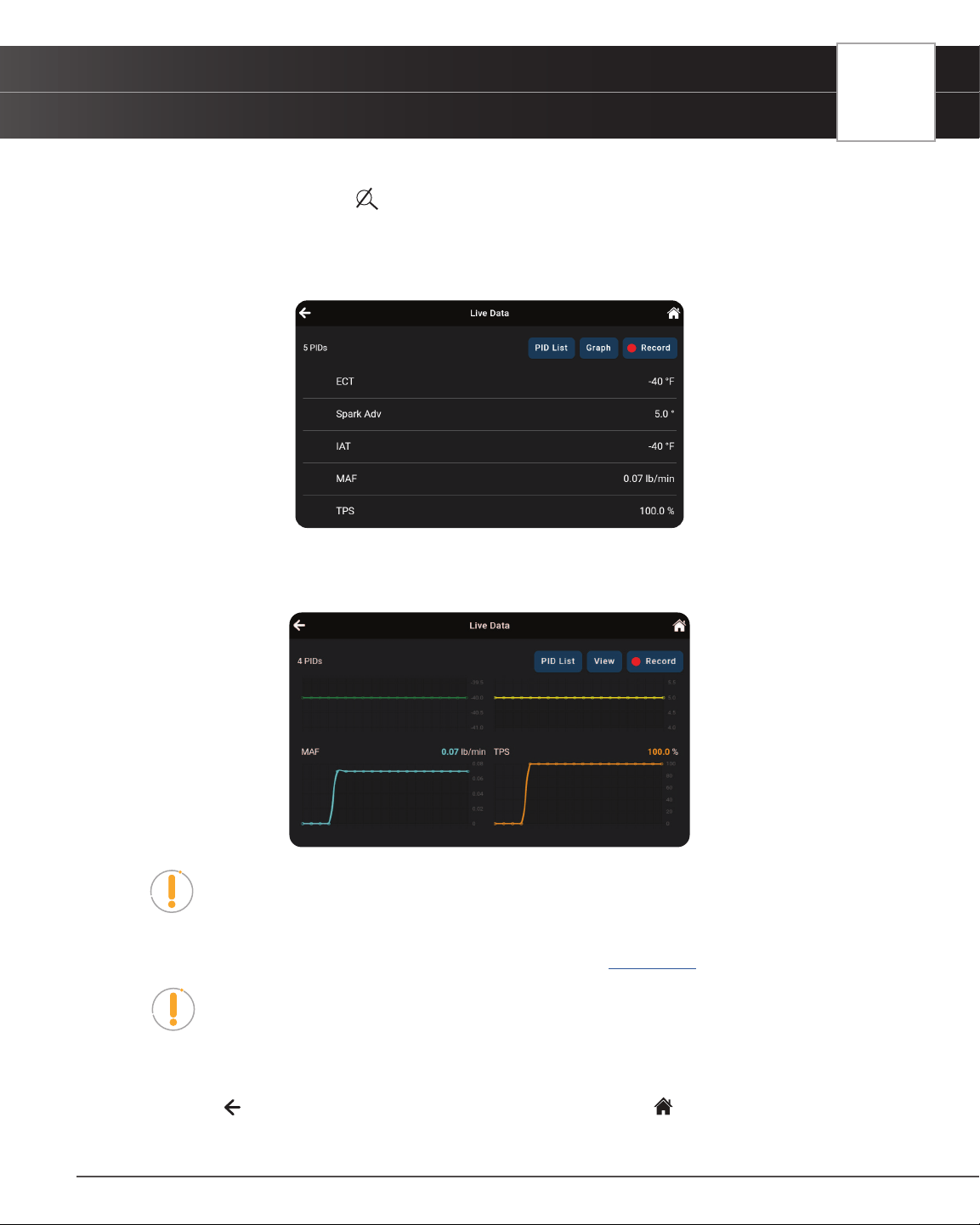
4. The results screen displays all of the vehicle’s
available PIDs with reported values. Each PID
is unselected to offer customization on which
component you wish to select and explore
further. A total PID count is provided at the top
left of the screen.
NOTE: The View, Graph, and Unselect
buttons remain “disabled” until a PID is
selected from the list.
5. Select the PID(s) you wish to explore.
n A “checkmark” indicates the associated PID is selected for viewing.
n An “empty checkbox” indicates the PID is not selected for viewing.
n Tapping a checkbox repeatedly will toggle it on and off.
n Tap the Unselect button to unselect all PIDs.
6. Tap the “search”
icon to quickly search for the PID(s) you wish to view or graph.
OBD2 DIAGNOSTICS
Additional Testing Utilities
25
n Use the keyboard to type in the name of the PID(s) and select as desired.
n Tap the “hide search” icon to exit the search function and return to the PID list.
7. Tap the View button to view the selected PIDs data in tabular mode.
n Each entry in the table shows the name of the PID, and a numerical representation of the
current value for the PID.
n Tap PID List to return to the full PID results list. (Step 4 above)
8. Tap the Graph button to view the selected PIDs in graph mode.
NOTE: The Graph function button will stay inactive if the selected PID does not
report a numerical value. An example is the Fuel System Status PID, which reports
either Open Loop (OL) or Closed Loop (CL).
9. Tap the Record button to record the selected PIDs in real time. [
See page 26]
NOTE: Tapping the Record button without selecting any PIDs will record all of the
vehicle’s available PIDs.
10. When troubleshooting vehicle problems, use the Live Data / PID results displayed on the tablet and compare
them against the specications found in the vehicle’s repair manual.
11. Tap the
icon to return to the OBD2 Diagnostics results page, or the Home icon to exit.
26
OBD2 DIAGNOSTICS
Additional Testing Utilities
Recording (Capturing) Live Data
The tablet allows you to record and save Live Data information for each PID supported by the vehicle.
Place the tablet in Live Data mode as indicated in Live Data Mode [See page 24]
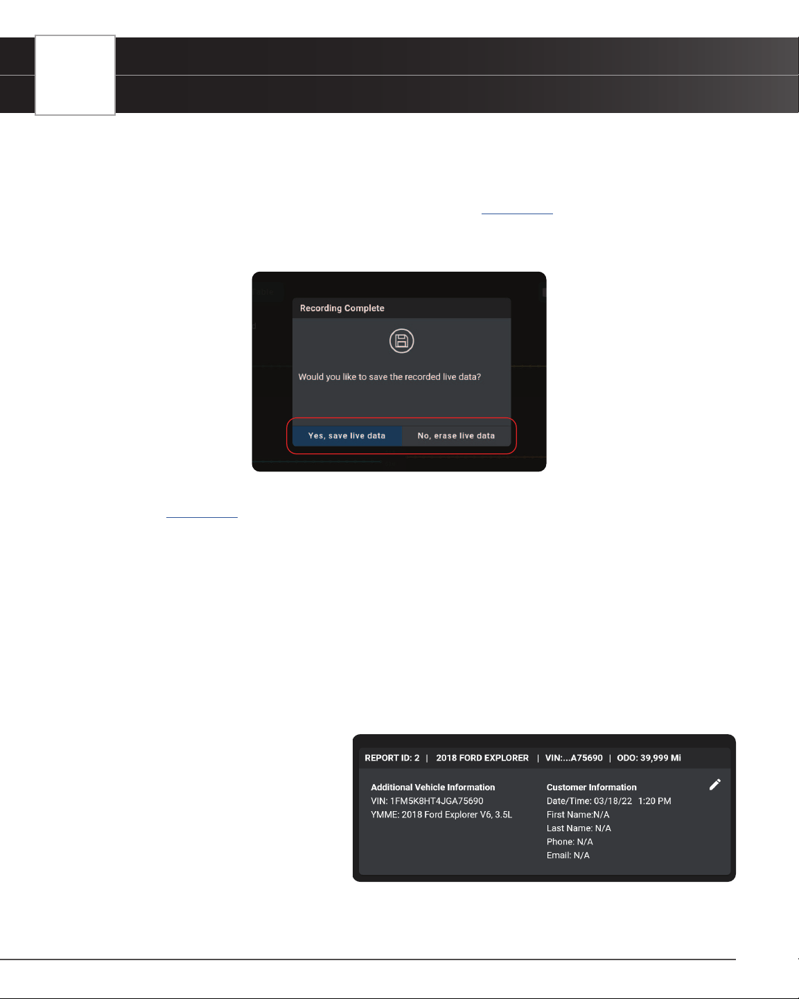
1. Tap Record to begin recording Live Data. Tap Stop to stop recording.
2. A “Recording Complete” dialog displays the message “Would you like to save the recorded live data?”
n Tap Yes, Save Live Data to save the recorded data to the tablet’s memory for later playback
[
See page 77].
n Tap No, Erase Live Data to discard the recorded data.
VEHICLE INFORMATION
The OBD2 DIAGNOSTICS test results page includes additional information, which can be accessed by tapping the
Vehicle Info button on the results page. This page allows you to view Customer Information, Vehicle ID, Available
Modules, and In-Use Performance Tracking (IPT).
1. Tap on the Vehicle Info button to display the details.
2. A dialog screen shows. Scroll to view each section.
Additional Vehicle Information &
Customer Information
n Additional Vehicle Informa-
tion – offers basic information
such as VIN and Year, Make
and Model of vehicle. More
details are accessible with the
Vehicle Information button.
n Customer Information – Includes the Date/Time at which the scan was run and the customer’s
OBD2 DIAGNOSTICS
Additional Testing Utilities
27
information, which can be edited using the icon.
[See page 28]
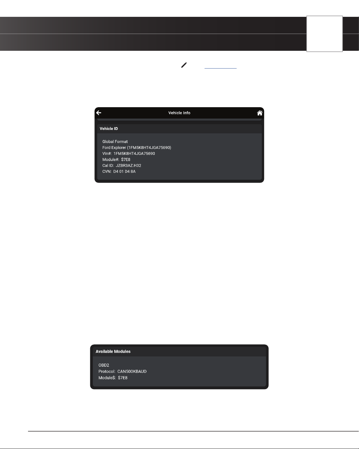
Vehicle ID
The Vehicle ID section displays the following information:
n VIN: The complete Vehicle Identication Number.
n YMME: The vehicle’s year, make, model and engine.
n Module No: The control module identication number(s).
n Cal ID: The vehicle’s calibration ID(s). These IDs uniquely identify the software version(s) for
the vehicle’s control module(s).
n CVN: The Vehicle’s Calibration Verication Number(s) (CVNs) required by OBD2 regulations.
CVNs are used to determine if emission-related calibrations for the vehicle under test have
been changed.
Available Modules
The Available Module section displays the following information:
n OBD2: Conrms the vehicle’s onboard diagnostic system is OBD2 compliant.
n Protocol: Lists the vehicle’s OBD2 communication protocol. This can be either ISO 9141,
Keyword 2000, J1850 PWM, J1850 VPW or CAN.
n Module$: Lists the primary control module’s identication number.
28
OBD2 DIAGNOSTICS
Additional Testing Utilities
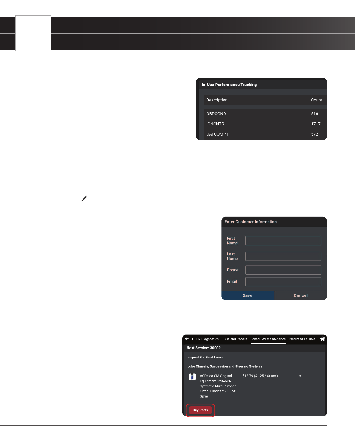
In-Use Performance Tracking (IPT)
The tablet can retrieve In-use Performance Tracking (IPT)
statistics for monitors supported by the vehicle under test.
Two values are returned for each monitor; the number
of times that all conditions necessary for a specic
monitor to detect a malfunction have been encountered
(XXXCOND), and the number of times that the vehicle
has been operated under the specic conditions for the
monitor (XXXCOMP). Statistics are also provided for the
number of times the vehicle has been operated in OBD
monitoring conditions (OBDCOND), and the number of times the vehicle’s engine has been started (IGNCNTR).
EDITING CUSTOMER INFORMATION
Each vehicle scan can be personalized by adding the customer’s information, including their First Name, Last Name,
Phone and Email.
1. Tap the
icon to display the Edit Customer Information elds.
2. Tap the eld you wish to edit, then enter the desired value using the keyboard.
n Enter the Phone number (including area code) as a
10-digit number, without spaces or other characters
(Example: 8005551212).
n Be sure to use a properly formatted Email address
(Example: [email protected]).
3. When all desired information has been entered, tap Save to
save your changes.
n A conrmation message displays when customer
information has been successfully saved.
━ If an invalid Phone number or Email address has
been entered, an advisory message displays. Tap Close to return to the Edit Customer
Information elds. Make the necessary correction(s), then tap Save to save your changes.
SCHEDULED MAINTENANCE
The Scheduled Maintenance page provides a listing
of scheduled maintenance procedures due at the
next service interval. The Next Service eld shows
the odometer reading at which the associated service
procedures are due.
Each entry in the list shows a scheduled inspection or
repair/ replacement procedure. In cases of replacement
procedures, the entry shows the required replacement
OBD2 DIAGNOSTICS
Additional Testing Utilities
29
part(s), the “per unit” part cost, and the number of parts required for the procedure.
Tap the Buy Parts button to access the web page for your preferred online parts supplier.
NOTE: The tablet uses the value entered in the Retailer section of the SETTINGS
page to determine your preferred parts supplier. [See page 80]
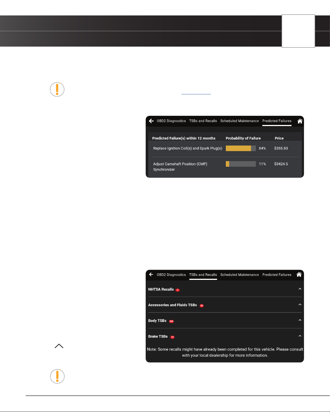
PREDICTED FAILURES
The Predicted Failure page provides a
listing of components and systems that may
experience a failure within the next 12-month
period. Each is based on historical data
taken from millions of real-world vehicle
repair records collected for over 25 years by
Innova’s network of ASE Master Technicians
across the U.S.
Each entry in the list provides the following information:
n Predicted Failure(s) within 12 months: A brief description of the predicted failure/repair/
maintenance procedure required.
n Probability of Failure: Expressed as a percentage of 100; shows a bar graph and numerical
value. The higher the value, the most likely the failure will occur.
n Price: Estimated cost to accomplish the associated repair/ maintenance procedure.
TSBs AND RECALLS
The TSBs and Recalls page provides a listing
of all Technical Service Bulletins (TSBs) and
Recalls issued against the vehicle.
TSBs and Recalls are grouped in categories
(NHTSA Recalls, Body TSBs, Electrical TSBs,
Factory Recalls, etc.). The number of items
in each category is shown following the
category name.
Tap the
icon for a category to expand
the category and view the full text of the
associated TSBs or recalls.
NOTE: Some TSBs and/or recalls for the vehicle may have already been
accomplished.
30
OEM DIAGNOSTICS
Performing a Scan – OEM Diagnostics
OEM DIAGNOSTICS
The OEM Diagnostics function allows you to perform enhanced, OEM
level diagnostics not available over generic OBD2. Access ABS, Airbag,
Transmission, Tire Pressure, Battery, and many body control modules to view
and erase their DTCs. Perform bi-directional tests on fuel pumps, injectors,
ignition coils, and much more. Plus, get access to hundreds of additional
parameters that you can view in real-time.
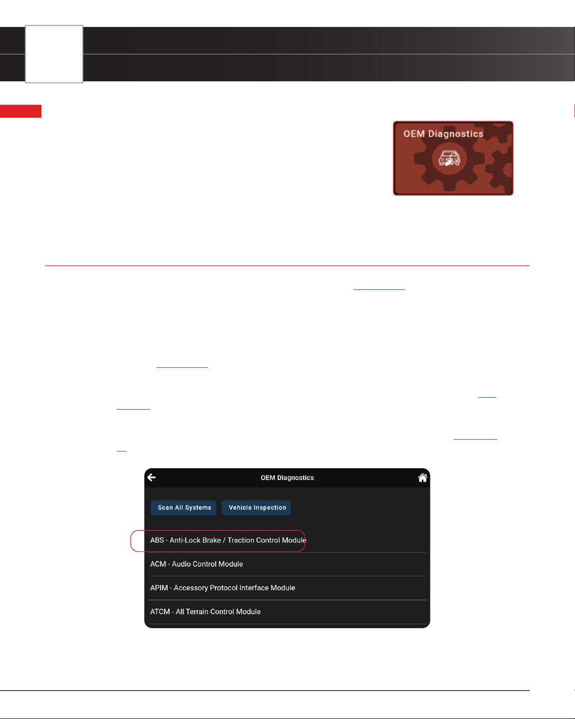
PERFORMING A SCAN – OEM DIAGNOSTICS
1. Follow the AutoLink Connection steps to connect with the vehicle [See page 12].
2. Tap OEM Diagnostics.
3. A selection dialog is provided.
4. Select the type of test you wish to perform.
n Tap Scan All Systems to perform a comprehensive vehicle scan of all available network
modules [
See page 31].
n Tap Vehicle Inspection to perform a complete vehicle health status report, including: OBD2
check, all network system scan, service checks, warning lights, tire pressures, and more [
See
page 38
].
n Tap the “individual” listed control module name (for example: ABS - Anti-Lock Brake /
Traction Control Module) to perform a diagnostic check on that single module. [
See page
32
]
OEM DIAGNOSTICS
Scan All Systems
31
SCAN ALL SYSTEMS
1. From the OEM Diagnostics results screen, tap Scan All Systems.
2. A progress bar appears, “Retrieving Vehicle Information...”, while the tablet scans all the vehicle’s equipped
modules. Please note that it will take a few moments while it scans all of the vehicle’s systems.
n Tap “Cancel” to stop the scan and return to the previous screen.
n On BMW models only follow this process:
━ Turn the ignition OFF, then back ON
━ Tap Continue to complete the scan
n If the Scan Tool fails to link to the vehicle’s computer, a “Scan Failed” message shows.
━ Ensure the vehicle is OBD2 compliant.
━ Verify the connection at the DLC, and verify the ignition is ON.
━ Turn the ignition OFF, wait 5 seconds, then back ON to reset the computer.
━ Tap Try Again to try again; or tap Cancel to return to the Home Page.
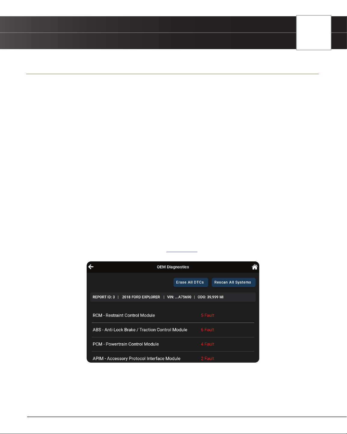
3. The Scan All Systems screen displays the diagnostic test results.
VIEWING THE “SCAN ALL SYSTEMS” TEST RESULTS
Scan results are shown immediately following completion of a scan; and can also be viewed later using the PREVIOUS
VEHICLE function available through the Home page. [
See page 75]
Each report begins with a vehicle information bar that includes a Report ID, the vehicle’s description (year/make/
model), the last six digits of the Vehicle Identication Number (VIN) and the odometer reading (ODO) at the time the
scan was performed.
The results window lists all tested Control Modules with its corresponding result:
32
OEM DIAGNOSTICS
Scan All Systems
n # Fault – Indicates the number of reported DTCs.
n No Fault – Indicates that no DTCs were found.
n Available – Indicates that the module is part of the system but does not report DTCs.
The results screen also allows to either:
n Erase All DTCs - Erases ALL of the vehicle’s retrieved Diagnostic Trouble Codes (DTC). [See
page 37
]
n Rescan All Systems - Performs a complete “Scan All Systems” report. [See page 31]
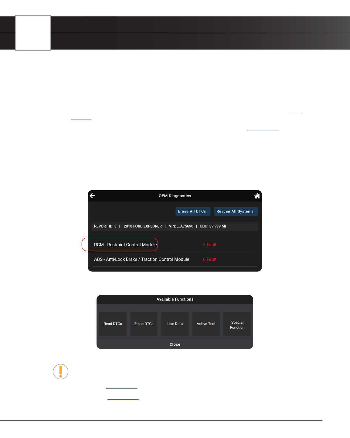
VIEWING & SCANNING AN INDIVIDUAL CONTROL MODULE
Perform diagnostics for a single, selected vehicle module. Depending on the module selected, you can Read DTCs,
Erase DTCs, view Live Data, and perform Active Test and/or Special Function procedures.
1. From the Scan All Systems results page, tap the name of the module you wish to explore further.
2. The Available Functions dialog selection screen is provided.
3. Tap on the corresponding button to perform the function you would like to run. Or, tap Close to exit.
NOTE: Actions that are not available for the selected module are “grayed” out.
n Read DTCs – See page 33
n Erase DTCs – See page 33
OEM DIAGNOSTICS
Scan All Systems
33
n Live Data – See page 34
n Active Test – See page 35
n Special Function – See page 36
Reading DTCs for a Selected Module
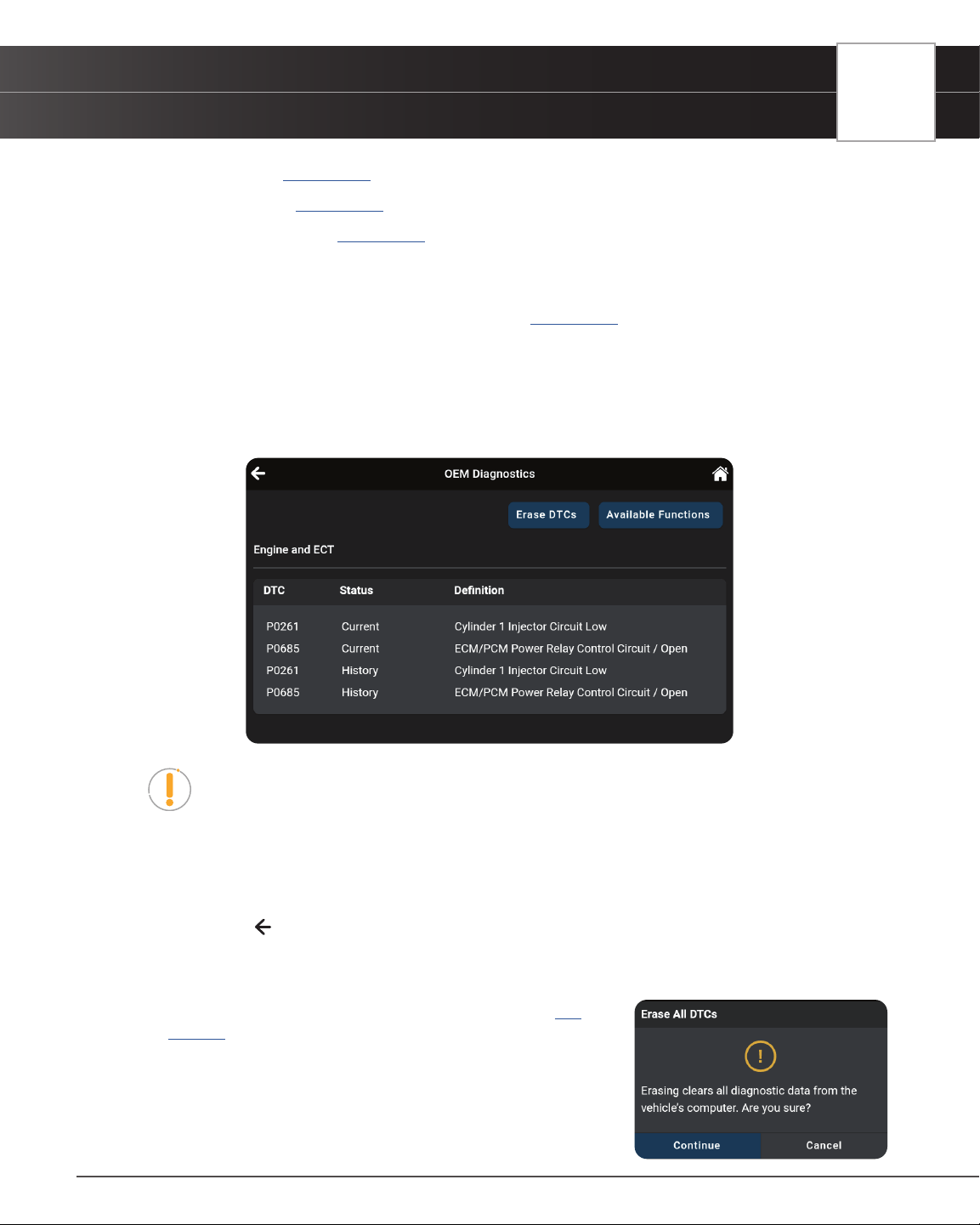
1. Select the module for which you wish to read DTCs. [See page 32]
2. Tap Read DTCs in the “Available Functions” menu.
n The tablet retrieves and displays DTCs stored in the vehicle’s computer for the currently
selected module.
n Each entry shows the DTC number, type, and denition.
NOTE: If no DTCs for the selected module are currently stored in the vehicle’s
computer, the message “No DTCs” displays.
3. Continue as desired:
n Tap the Erase DTCs button to erase ALL retrieved Diagnostic Trouble Codes (DTCs)
n Tap the Available Functions button to open its selection menu.
n Tap the
icon at the top left of the screen to return to the All Systems Scan screen.
Erasing DTCs for a Selected Module
1. Select the module for which you wish to read its DTCs. [See
page 32
]
2. Tap Erase DTCs in the “Available Functions” menu. A
conrmation message shows.
n Ensure that the ignition in the Key ON, Engine OFF position.
n If you are sure you want to proceed, tap Continue.
34
OEM DIAGNOSTICS
Scan All Systems
n If you do not want to proceed, tap Cancel to cancel the erase procedure.
3. If you chose to erase DTCs, an “Erasing DTCs…” message displays while the erase function is in progress.
n If the erase was successful, a conrmation message shows. Tap Scan Again to re-scan the
currently selected module; or tap Close to exit and return to the test results screen.
n If the erase was not successful, an advisory message shows. Make sure the tablet is properly
connected to the vehicle’s DLC, then tap Try Again to repeat the erase procedures.
━ Tap Cancel to cancel the erase procedure and close the message.
Viewing Live Data for a Selected Module
You can view Live Data for the currently selected module.
1. While linked to the vehicle, start the engine.
2. Select the module for which you wish to view Live Data. [
See page 32]
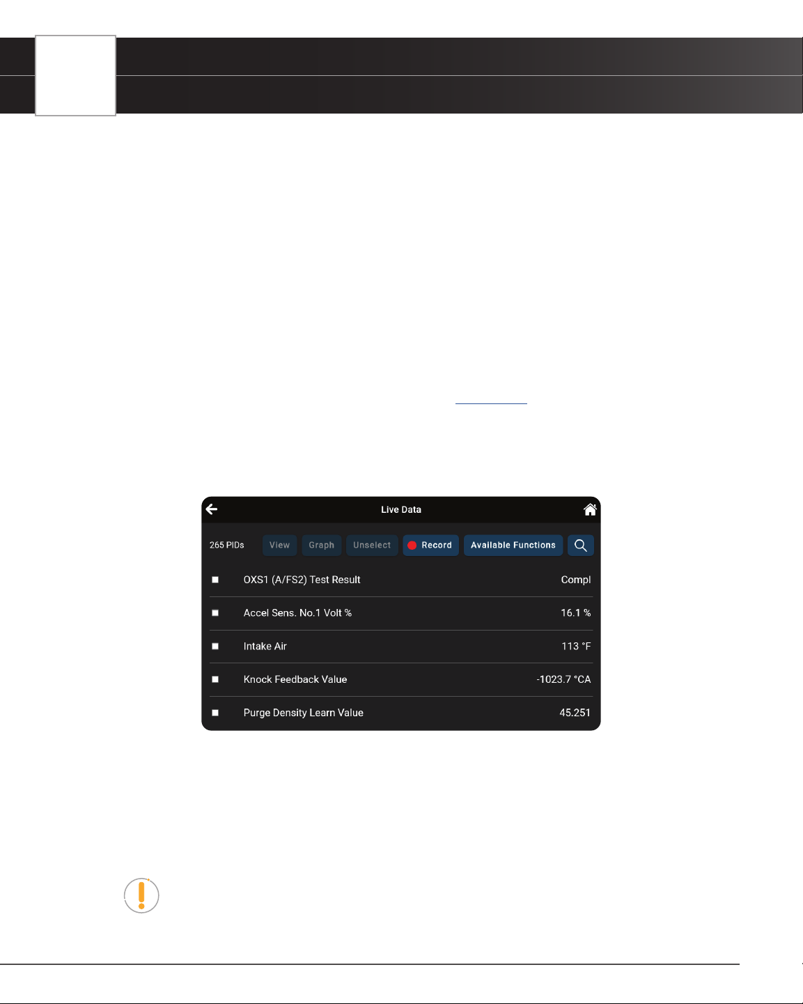
3. Tap Live Data in the “Available Functions” menu to place the tablet in Live Data mode.
4. The results screen displays all of the vehicle’s available PIDs with reported values. Each PID is unselected to
offer customization on which component you wish to select and explore further. A total PID count is provided
at the top left of the screen.
5. Select the PIDs you wish to explore further and continue as desired:
n Tap the View button to view PID data in a tabular format.
n Tap the Graph button to view PID data in graphical format.
n Tap the Unselect button to unselect all PID parameters.
n Tap Record to record the selected Live Data PID(s) in real time.
NOTE: Tapping the Record button without selecting any PIDs will record all of the
vehicle’s available PIDs.
n Tap the Available Functions button to open its selection menu.
OEM DIAGNOSTICS
Scan All Systems
35
n Tap the icon to quickly search and select desired PID(s).
n Tap the icon at the top left of the screen to return to the All Systems Scan screen
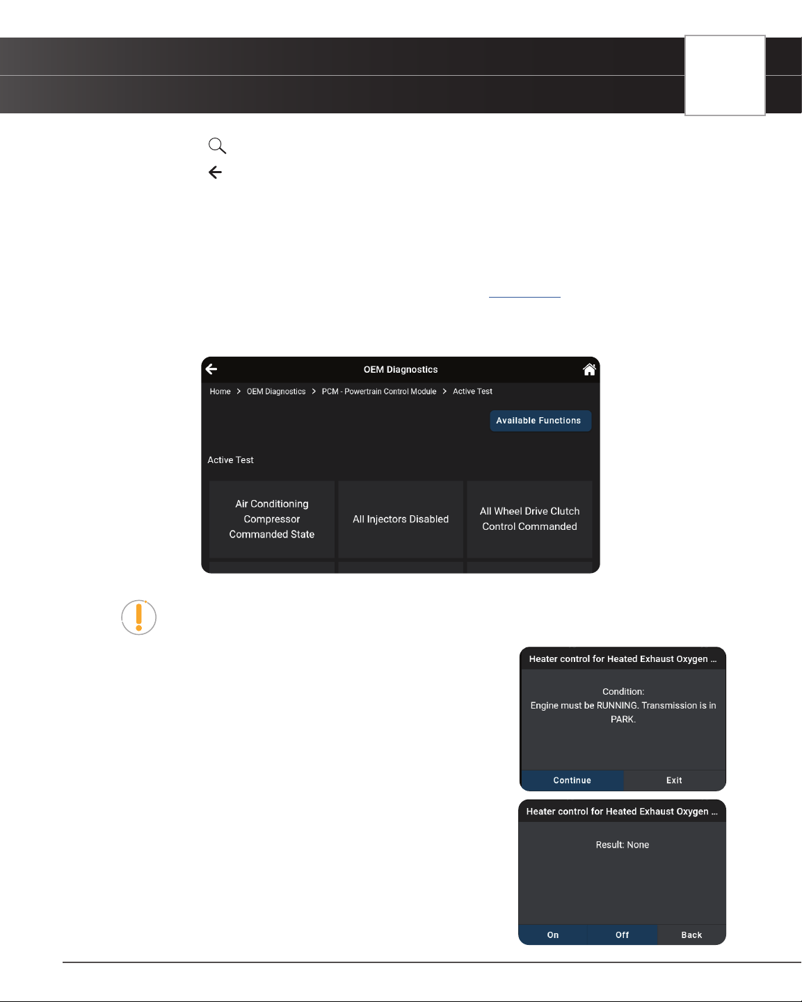
Performing Active Tests for a Selected Module
Active Tests let you perform active tests for various vehicle actuators and systems. The specic tests available
depend on the vehicle make and model.
1. Select the module for which you wish to perform Active Tests. [
See page 32]
2. Tap Active Test in the “Available Functions” menu.
n The tablet retrieves and displays a menu of Active Tests available for the vehicle under test.
NOTE: If Active Tests are not supported for the vehicle under test, the message
“Active Test is not supported for this vehicle” displays. Tap Exit to return to the
previous page.
n Choose the desired test.
n The tablet may display one or more instructional screens to
prepare the vehicle for testing.
3. Prepare the vehicle for testing, as necessary.
n The tablet displays a “control” screen to run the test.
4. Tap the appropriate control to operate the actuator as desired.
n The screen refreshes to show the result.
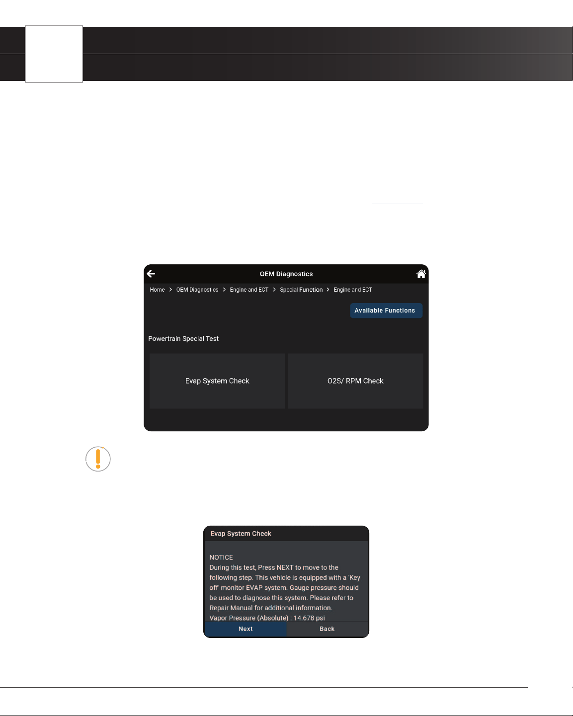
36
OEM DIAGNOSTICS
Scan All Systems
5. Repeat step 3 as desired.
6. Tap Back to return to the Active Test menu.
Performing Special Functions for a Selected Module
Special Functions let you perform diagnostic and calibration procedures for various vehicle actuators and systems.
The specic tests available depend on the vehicle make and model.
1. Select the module for which you wish to perform Special Functions. [
See page 32]
2. Tap Special Function in the “Available Functions” menu.
n The tablet retrieves and displays one or more menus of Special Functions available for the
vehicle under test.
NOTE: If Special Functions are not supported for the vehicle under test, the
message “Special Function is not supported for this vehicle” displays. Tap Exit to
return to the previous page.
3. Make the necessary selections to choose the desired test.
n A series of instructional screens display.
4. Follow the on-screen prompts to prepare the vehicle for testing, and to perform the selected test procedure.
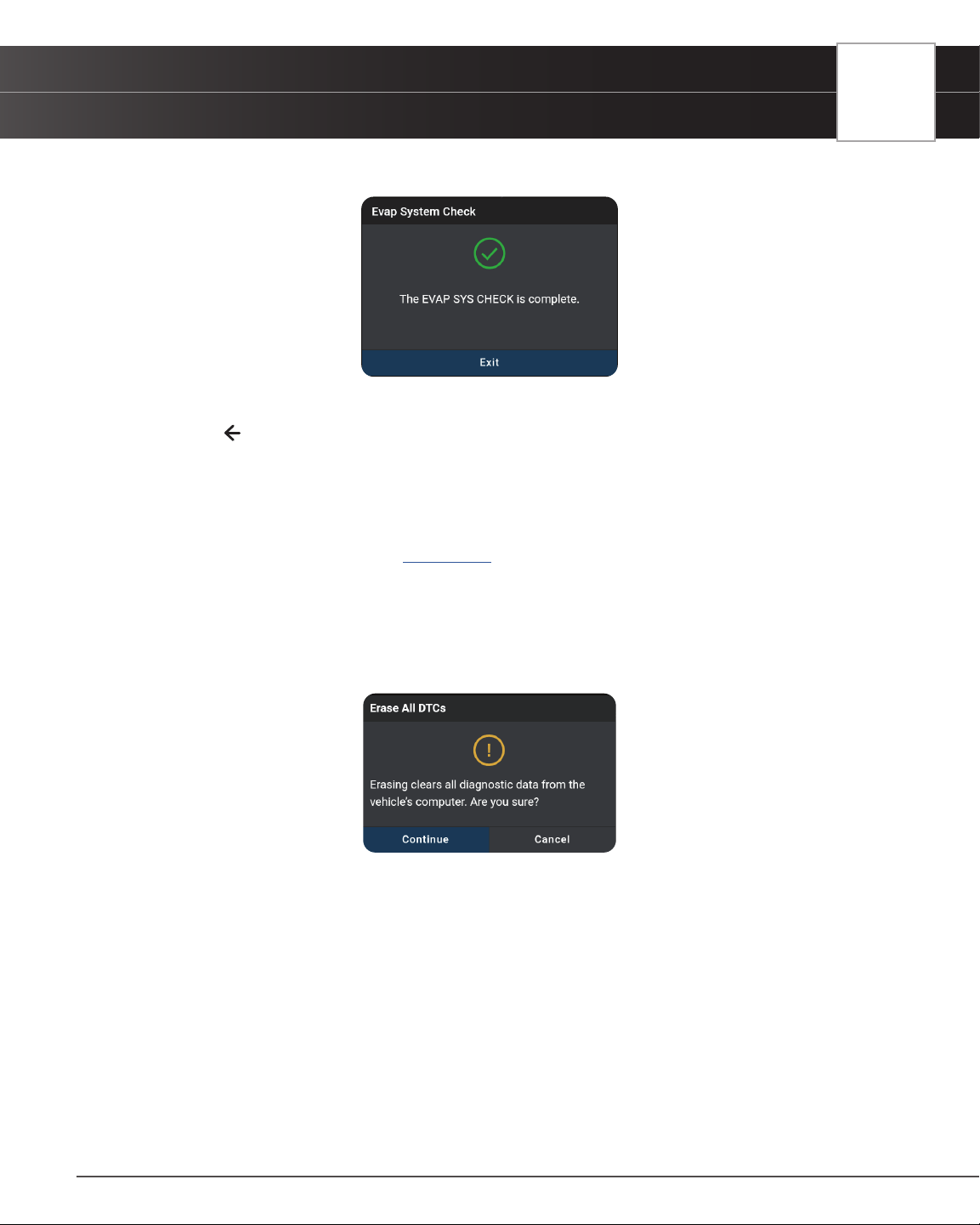
OEM DIAGNOSTICS
Scan All Systems
37
n A “results” screen displays when the test procedure has completed.
5. Tap Finish or Exit to return to the previous menu.
6. Tap the
icon at the top left of the screen to return to previous page.
ERASE ALL OEM DTCs
Erase all the stored OEM DTCs from the vehicle’s computer memory as follows:
1. Perform the Scan All Systems steps. [See page 31]
2. If the tablet is already connected and linked to the vehicle’s computer, proceed directly to Step 2.
n Ensure that the ignition in the Key ON, Engine OFF position
3. Tap the Erase All DTCs button at the top of the Scan All Systems results page.
n The tablet displays an attention message conrming deletion.
n If you want to proceed, tap Continue.
n If you do not want to proceed, choose Cancel to exit the erase procedure.
4. By selecting to Erase DTCs, a “One moment please…” progress dialog displays during the erase process.
n If the erase was successful, a conrmation dialog displays.
5. If the erase was not successful, an advisory dialog displays with instructions with either:
n “Turn the ignition off, then turn the ignition on” = follow steps and tap Erase DTCs to resume.
(Or)
n “Erase has failed” = tap Erase Again to try again.
6. Once all DTCs are erased, tap Scan Again to conrm that all DTCs were erased.
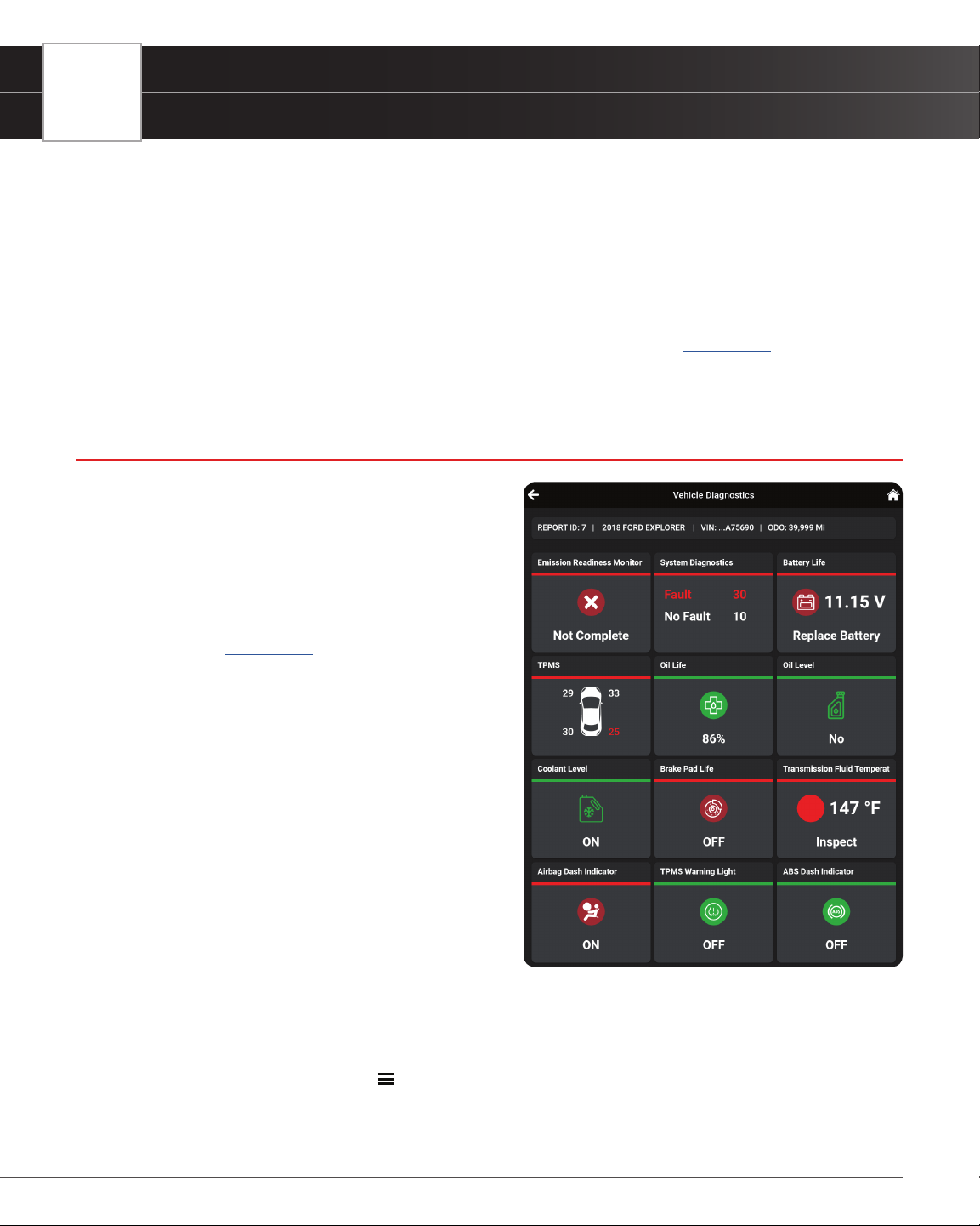
38
OEM DIAGNOSTICS
Vehicle Inspection Health Report
n Or tap Close to exit.
RESCAN ALL SYSTEMS
Use this function to get the most current diagnostic status for the vehicle under test – particularly as you continue to
troubleshoot each individual control module.
1. From the “Scan All Systems” result page, tap Rescan All Systems button at the top right of the page.
2. Tool generates a new report and updates the “Scan All Systems” results page. [
See page 31]
VEHICLE INSPECTION HEALTH REPORT
The Vehicle Inspection report, also considered a full
Network Scan, provides a complete overview of the
vehicle’s current health status. It reports the vehicle’s
emission readiness status, system status, service status,
dashboard warning light status, and a RepairSolutions2
diagnostic report.
1. Follow the Scan All Systems steps to connect with
the vehicle. [
See page 31]
2. From the OEM Diagnostics results screen, tap the
Vehicle Inspection button.
3. A progress bar appears, “Retrieving Vehicle
Information...”, while the tablet scans all of the
vehicle’s equipped modules.
n It can take several minutes depending on
the number of available systems available
on the vehicle being tested. Tap Cancel to
abort the scan.
n If the Vehicle Inspection was recently
performed, a “...Are you sure?” warning
dialog appears prior to the scan. Tap
Continue to complete the scan, or tap
Cancel to return to the previous screen.
VIEWING THE VEHICLE INSPECTION TEST RESULTS
Scan results are shown immediately following completion of a scan; and can also be viewed later using the PREVIOUS
VEHICLE function available through the
Menu or Home page. [See page 75].
Each report begins with a vehicle information tab that includes a Report ID, the vehicle’s description (year/make/

OEM DIAGNOSTICS
Vehicle Inspection Health Report
39
model), the last six digits of the Vehicle Identication Number (VIN) and the odometer reading (ODO) at the time the
scan was performed.
Emissions Readiness Monitors Status
Indicates whether the vehicle is ready for an Emissions Test (Smog Check) based on DTCs present, Freeze Frame
data, Monitor Status, MIL (Check Engine Light) status, State/Region, and Engine Type. Results are shown as
“Complete” or “Not Complete”.
n Emission Readiness Monitor - For a “Not Complete” result, Drive Cycle Procedures can be
found in the OBD2 Diagnostics screen. [
See page 19]
System Diagnostics (DTC Status Overview)
Gives a quick snapshot of all Diagnostic Trouble Codes (DTCs) found on the vehicle with “Fault – DTCs reported”
or “No Fault – no DTCs present”.
n Tap the Systems Diagnostics tab to open the Scan All Systems window to view scan details
[
See page 31]
Vehicle Service Status
Some vehicles are capable of checking and reporting on its various service items. If available, the tablet displays
these as individual tab segments as dened below. Use these results to share with customer or to create a service
due task list.
n Battery Life: Indicates the current battery charge voltage and suggests if the battery requires
replacement. The Battery Life eld is color-coded to provide a visual indication of battery status:
Green = good; Yellow = poor; Red = replace battery.
n TPMS / Tire Pressure Readings: Shows the status of the vehicle Tire Pressure Monitoring
System (TPMS) and the individual tire pressures for all vehicle tires. The TPMS eld is color-
coded to provide a visual indication of tire pressure status: Green = good; Red = low pressure.
n Oil Life: Shows the current oil life for the vehicles lubricating oil as a percentage of 100. The
Oil Life eld is color-coded to provide a visual indication of oil life status: Green = good; Red
= poor.
n Oil Level: Shows if the level is normal or below the manufacturer’s set threshold: Green =
Good; Red: Low Level Warning
n Coolant Level: Indicates if the coolant reservoir is lled to the recommended manufacturer
specications. The Coolant Level is color-coded and provides a visual status: Green = OK;
Red = Low
n Brake Pad Life – Front & Rear: Shows the current measured brake pad life for the Front and
Real axle as a percentage of 100. The Brake Pad Life is color-coded and provides a visual
status: Green = OK; Red = Not OK
n Transmission Fluid Temperature: Shows the current measure temperature of the vehicle’s
Transmission Fluid Temperature. The temperature is color-coded and provides a visual status:

40
WORKSHOP TOOLS
Vehicle Inspection Health Report
Green = Good Condition; Red = Inspect
Dashboard Warning Light Status
The tablet can read if the vehicle’s systems are reporting a dashboard warning light status. If available for the
vehicle under test, the tablet displays these as individual tab segments as dened below. Use these as part of the
inspection process to conrm a lit dashboard warning light.
n Airbag Dash Indicator: Reports if the airbag dashboard light is currently ON or OFF. It is color-
coded to provide a quick visual status: Red = ON; Green = OFF.
n TPMS Warning Light: Reports if the Tire Pressure Monitoring System (TPMS) dashboard light
is currently ON or OFF. It is color-coded to provide a quick visual status: Red = ON; Green =
OFF.
n ABS Dash Indicator: Reports if the Anti-Lock Brake System (ABS) dashboard light is currently
ON or OFF. It is color-coded to provide a quick visual status: Red = ON; Green = OFF.
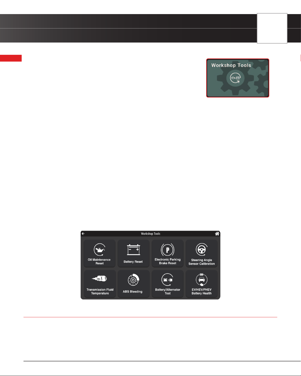
WORKSHOP TOOLS
Oil Maintenance Reset
41
WORKSHOP TOOLS
The WORKSHOP TOOLS tab allows you to perform over 30 OEM service
reset procedures. Depending on the vehicle being tested, the tablet will only
display the procedures which are specic to your vehicle. It can include a
combination from any of the following reset procedures.
AVAILABLE WORKSHOP TOOLS
A/F Setting Headlamp Calibration
Steering Angle Sensor
Calibration
ABS Bleeding Immobilizer Reset Suspension Calibration
AC System Relearn Injector Coding
Throttle Body Relearn/TEC
Learn
AdBlue Reset Key Coding Procedure Tire Size Reset
Battery Reset Language Change Reset TPMS Relearn
Battery/Alternator Test Maintenance Reset
Transmission Fluid Level
Check
Clutch Relearn NOx Sensor Reset
Transmission Fluid
Temperature
Coolant Bleeding Occupant Seat Sensor Calibration Transmission Reset
DPF Reset Odometer Reset Transport Mode
Electric Parking Brake (EPB)
Reset
Oil Maintenance Reset Window Door Roof
EV/HEV/PHEV Battery Health Reset Electric Traction System
OIL MAINTENANCE RESET
Resetting the Oil Maintenance Light
1. Tap Oil Maintenance Reset on the Workshop Tools screen.
n An “instructional” dialog displays to conrm selection.
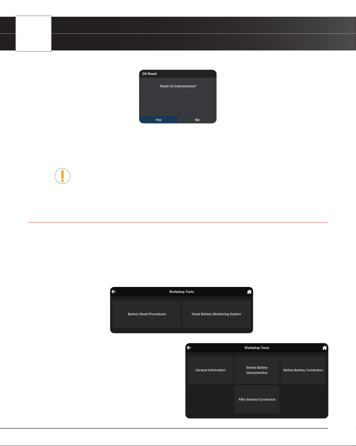
42
WORKSHOP TOOLS
Battery Reset
n Select Yes to continue. Or, No to cancel.
n A “One moment” message displays while the procedure is in process.
2. When the reset process has competed, a conrmation message displays. Tap Exit to return to the Workshop
Tools screen.
n If the oil reset was not successful, an advisory message displays.
NOTE: If the Scan Tool cannot reset the Oil Maintenance Light, an “instructional”
dialog displays, showing the manual procedures for resetting the indicator light.
When nished viewing the instructions, tap Back to return to the Workshop Tools
screen.
BATTERY RESET
You can use the tablet to view the procedures for resetting the battery monitor system following battery replacement or
perform battery reset OBD service (for Audi, BMW, Ford, Volkswagen, and Volvo models only).
To view battery reset procedures:
1. Tap Battery Reset on the Workshop Tools screen.
n The Battery Reset menu displays.
2. Tap Battery Reset Procedures.
n The Battery Reset Procedures menu
displays. The menu provides access to
General Information, and procedures to be
followed Before Battery Disconnection,
Before Battery Connection, and After
Battery Connection.
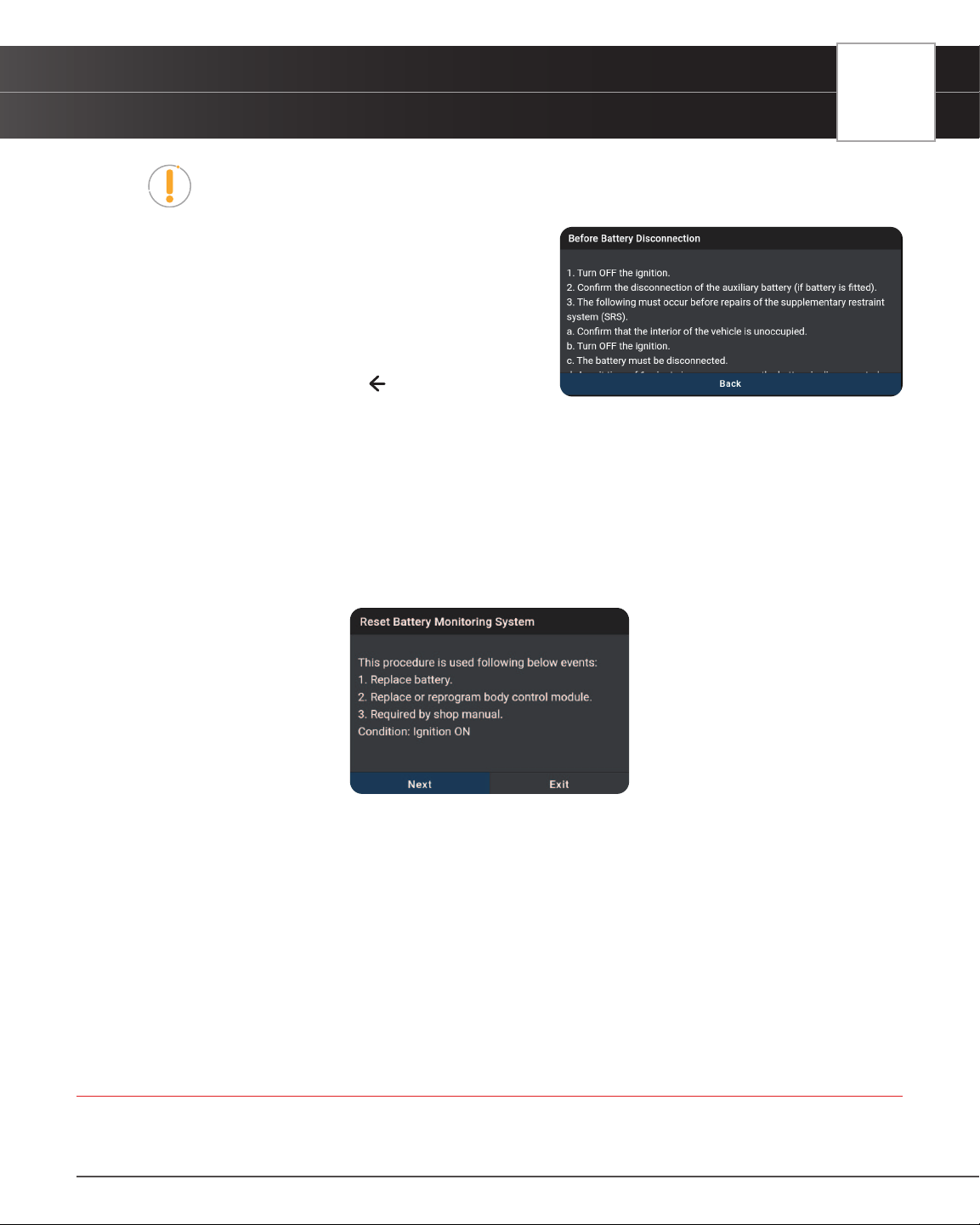
WORKSHOP TOOLS
Electronic Parking Brake (EPB) Reset
43
NOTE: If battery reset procedures are not available, an advisory message shows.
Tap Back to return to the Workshop Tools screen.
3. Tap the procedure you wish to view.
n The selected procedure displays.
4. When you have nished viewing the retrieved information,
tap Back to return to the Battery Reset Procedures menu.
Repeat step # 3 to view additional procedures.
n When you have nished viewing all desired
procedures, tap on the
icon at the top of the
page to return to the Workshop Tools screen.
To perform battery reset OBD service:
1. Tap Battery Reset on the Workshop Tools screen.
n The Battery Reset menu displays.
2. Tap Reset Battery Monitoring System or Battery Replacement Registration – available selection depends on
the vehicle being serviced.
n An “instructional” message displays.
3. Follow the instructions provided to prepare the vehicle for battery reset OBD service. When all necessary
procedures have been performed, tap Next to continue.
n A “One moment please…” message displays while battery reset is in process.
4. If the battery reset process is successful, a “Reset Complete” message displays. Tap Exit to return to the
Workshop Tools screen.
n If the battery reset process is not successful, a “Reset Fail” message displays. Tap Exit to
return to the Workshop Tools screen.
ELECTRONIC PARKING BRAKE (EPB) RESET
The Electronic Parking Brake (EPB) reset procedures vary between vehicle makes and models.
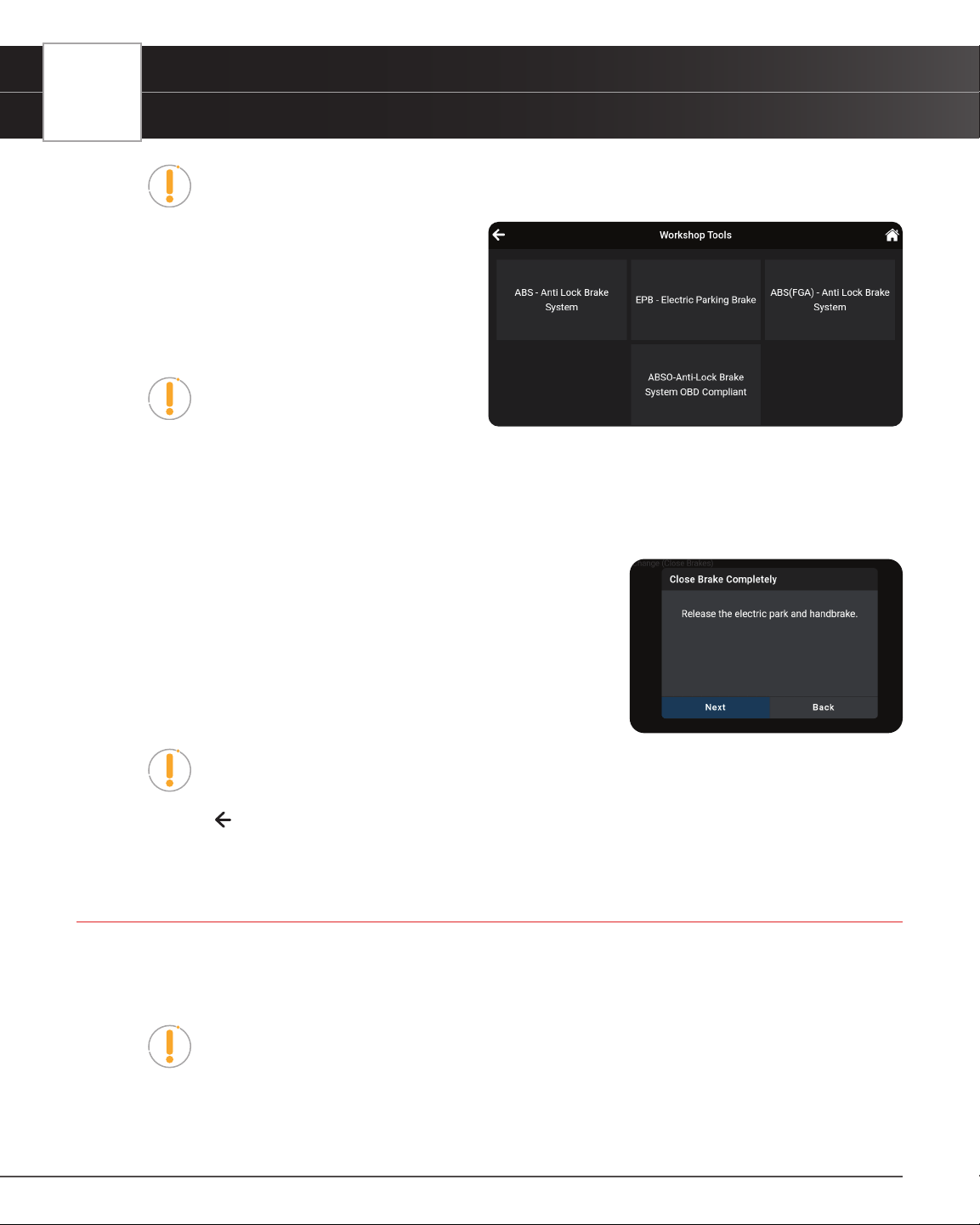
44
WORKSHOP TOOLS
Steering Angle Sensor (SAS) Calibration
NOTE: If an error occurs while performing calibration procedures, an “advisory”
message displays. Tap Exit to return to the Workshop Tools screen.
1. Tap Electronic Parking Brake Reset on the
Workshop Tools screen.
n For some vehicles, one or more sub-
menus display. Tap the desired module
and/or option, as appropriate. Proceed
to step 2.
NOTE: If Electric Parking Brake reset is
not supported by the vehicle under test,
an “advisory” message displays. Tap
OK to return to the Workshop Tools screen.
2. A “One moment” message displays, followed by one or more “informational/ instructional” or “selection” screens.
n Perform test procedures as directed. Tap Next, as appropriate, to continue to the next step.
3. For some vehicles, “status” screens display as each phase of the
calibration procedure is successfully completed. Tap Next, as
appropriate, to scroll to the next screen.
n A “One moment” message displays while the procedure is
in process.
n A “results” screen displays when the calibration procedure
has completed.
NOTE: If the procedure is stopped due to a communication error, an “advisory”
message displays. Tap Exit to return to the Workshop Tools screen.
4. Tap on the
icon at the top of the page to return to the Workshop Tools screen..
STEERING ANGLE SENSOR (SAS) CALIBRATION
The Steering Angle Sensor (SAS) Calibration function is available for BMW, Chrysler, Ford, GM, Hyundai/KIA,
Nissan, Toyota, Honda, Mitsubishi, Subaru, Jaguar, Volkswagen and Volvo vehicles only. Calibration procedures vary
between vehicle makes and models.
NOTE: If an error occurs while performing calibration procedures, an “advisory”
message displays. Tap Exit to return to the Service Reset menu.
1. Tap Steering Angle Sensor Calibration on the Workshop Tools screen.
n For some vehicles, one or more sub-menus display. Tap the desired module and/or option, as
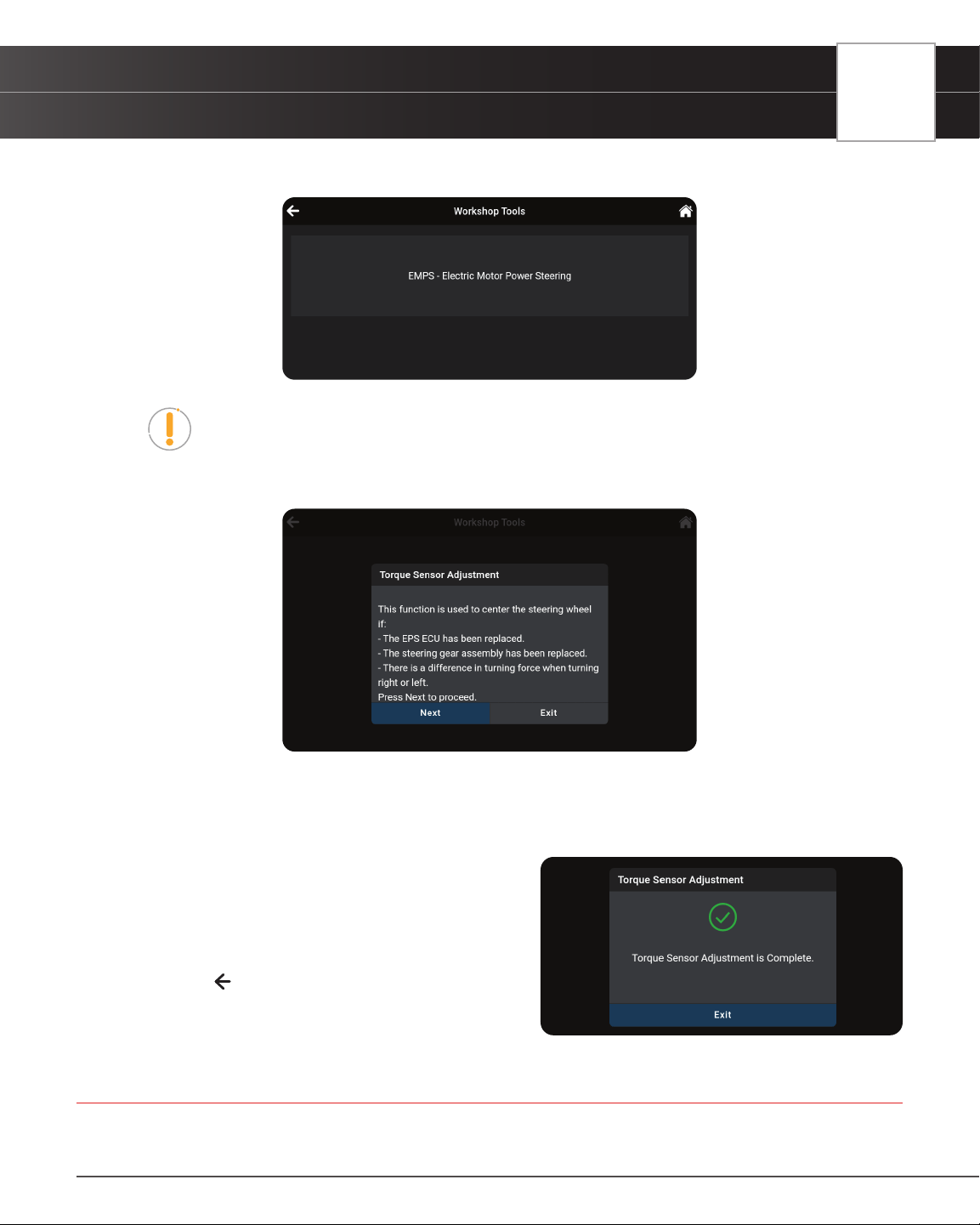
WORKSHOP TOOLS
Transmission Fluid Temperature
45
appropriate. Proceed to step 2.
NOTE: If SAS calibration is not supported by the vehicle under test, an “advisory”
message displays. Tap OK to return to the Service Reset menu.
2. A “One moment” message displays, followed by one or more “informational/ instructional” screens.
n Perform test procedures as directed. Tap Next or Continue, as appropriate, to scroll to the next
screen. Or, tap End or Exit to terminate the procedure.
3. For some vehicles, “status” screens display as each phase of the calibration procedure is successfully completed.
Tap Next, as appropriate, to scroll to the next screen.
n A “results” screen displays when the calibration
procedure has completed.
4. Tap End or Exit, as appropriate, to return to the SAS
Reset menu.
5. Tap on the
icon at the top of the page to return to the
Workshop Tools screen.
TRANSMISSION FLUID TEMPERATURE
Depending on the vehicle under test, the tablet allows to view temperature readings from the Transmission Fluid
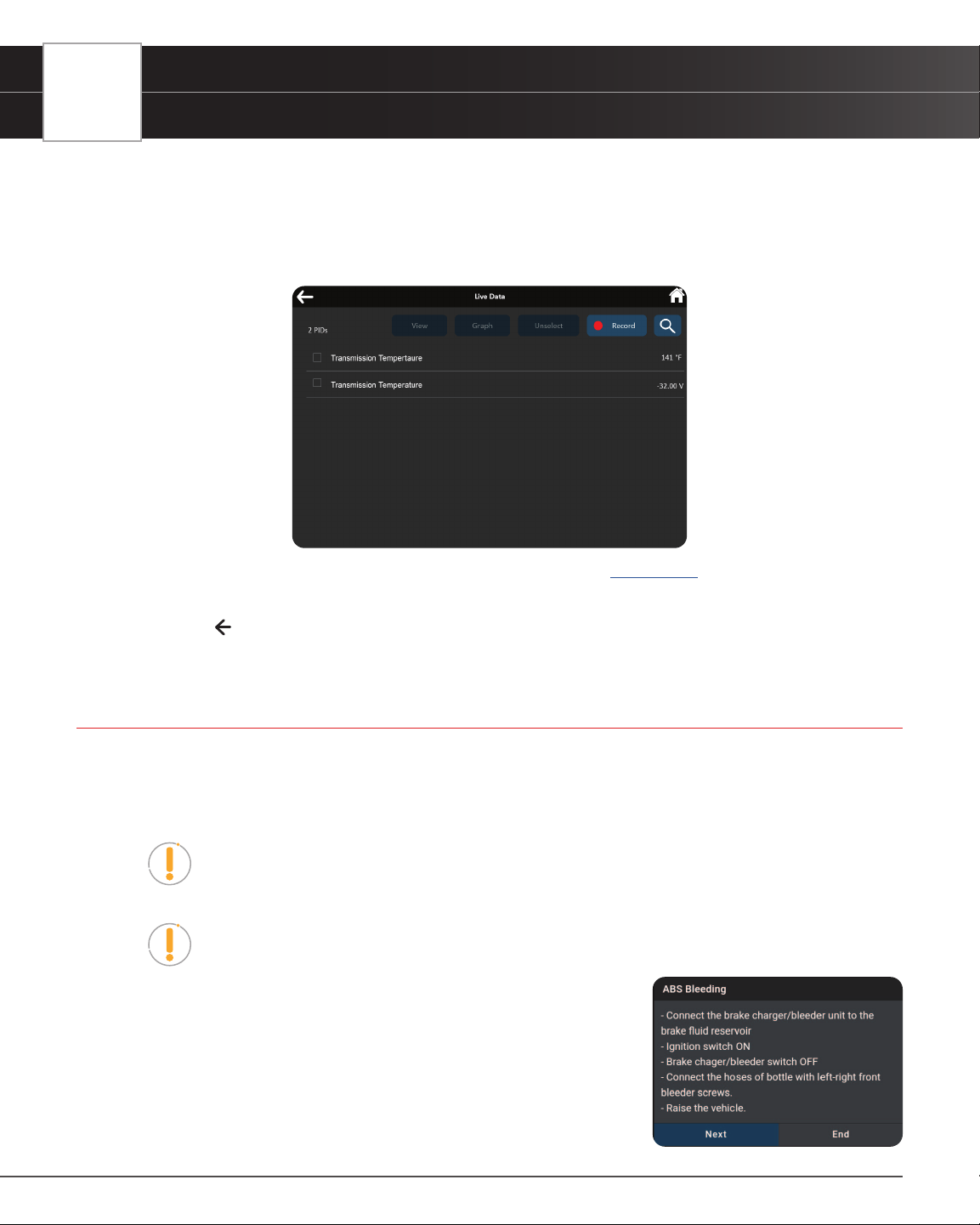
46
WORKSHOP TOOLS
ABS Bleeding
Temperature Sensor (TFT) to help identify transmission overheating issues.
1. Tap Transmission Fluid Temperature on the Workshop Tools screen.
n A “One one moment please...” progress dialog displays. Tap Cancel to cancel the operation.
2. The Transmission Temperature Live Data PID list displays.
3. Select the PID(s) you wish to view and tap View, Graph, or Record. [See page 24]
n Tap Unselect to unselect all PID parameters.
4. Tap on the
icon at the top of the page to return to the Workshop Tools screen.
ABS BLEEDING
The ABS Bleeding function is available for Chrysler, GM, Hyundai/KIA, Mazda, Toyota, Ford, Honda, Nissan, Mitsubishi,
Subaru, Volvo, Mercedes, Volkswagen, BMW, and Jaguar vehicles only. Procedures vary between vehicle makes and
models.
NOTE: If an error occurs while performing ABS bleeding procedures, an “advisory”
message displays. Tap Exit or Back, as necessary, to return to the Service Reset
menu.
NOTE: If ABS bleeding is not supported for the vehicle under test, an “advisory”
message displays. Tap Retry, as necessary, to return to the Service Reset menu.
1. Tap ABS Bleeding on the Workshop Tools screen.
n One or more sub-menus will display. Select the desired options,
then proceed to step 2.
2. One or more “informational/ instructional” screens display.
n Perform test procedures as directed. Tap Next to scroll to the
next step.
3. For some vehicles, “status” screens display as each phase of the
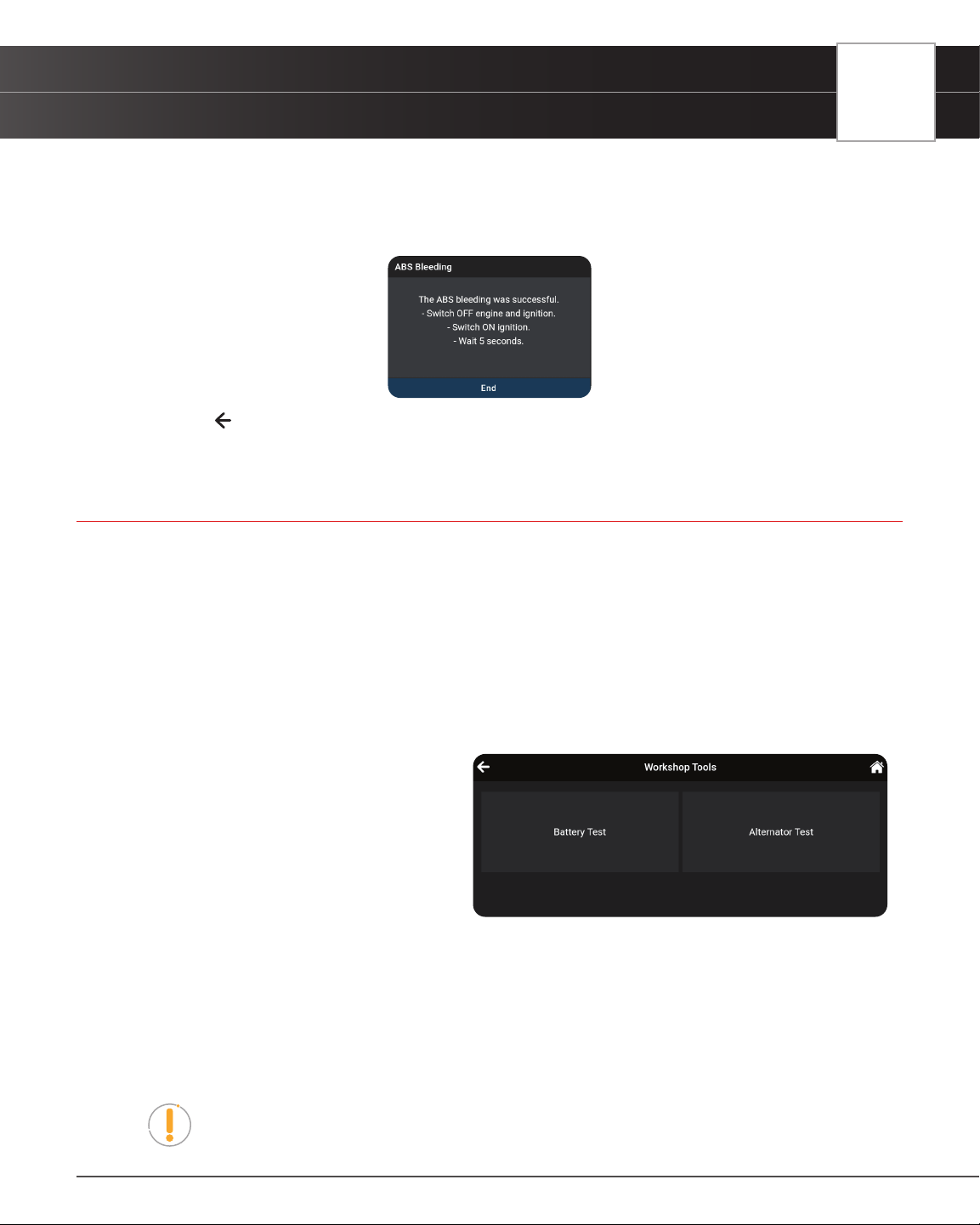
WORKSHOP TOOLS
Battery / Alternator Test
47
calibration procedure is successfully completed. Tap Next to scroll to the next step.
n A “results” message displays when the procedure has completed.
4. Tap End to close the results message.
5. Tap on the icon at the top of the page to return to the Workshop Tools screen.
BATTERY / ALTERNATOR TEST
The tablet can check the vehicle’s battery and alternator systems to ensure operations are within acceptable limits. You
can test just the battery (Battery Test) or check both the battery and alternator (Alternator Test).
BATTERY TEST ONLY
To perform a battery check ONLY:
1. Tap Battery / Alternator Test on the Workshop Tools screen.
n The Battery / Alternator Test menu displays.
2. Tap Battery Test.
n An “instructional” message displays,
showing the procedures to prepare
the vehicle for the battery check.
3. Prepare the vehicle for the battery check:
n Turn the engine off.
n Place the transmission in PARK or
NEUTRAL, and set the parking brake.
n Make a visual check of the battery’s condition. If the battery terminals are corroded or other
damage is present, clean or replace the battery as appropriate.
n For “unsealed” batteries, make sure the water level in each cell is above the battery plates.
n Turn the ignition on. DO NOT start the engine.
4. Tap Continue to proceed.
NOTE: If the engine is running, an advisory message shows. Turn the engine off,
then turn the ignition on. DO NOT start the engine. Tap Continue to proceed.
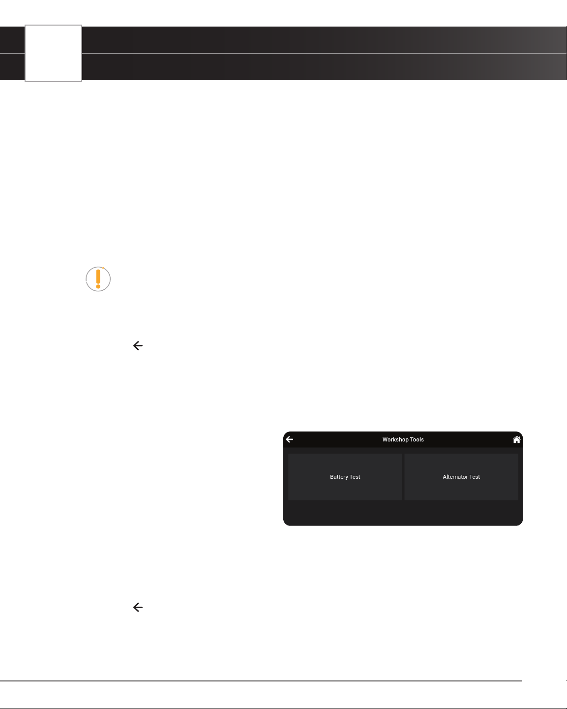
48
WORKSHOP TOOLS
Battery / Alternator Test
n An “instructional” message displays.
5. Turn the vehicle’s headlights on, then tap Continue to proceed.
n A “countdown” message shows while the battery check is in process.
n If battery voltage is less than 12.1 volts, an advisory message shows. Tap Home to return to the
Home Page. Turn the ignition off and disconnect the tablet from the vehicle. Fully charge the
battery, then repeat the battery check.
n If battery voltage is greater than 12.1 volts, an “instructional” message shows.
6. Turn the vehicle’s headlights off, then tap Continue to proceed.
n An “instructional” message shows.
7. Start the vehicle’s engine. Allow the engine to run for several seconds, then turn the engine off.
NOTE: If the tablet did not detect “cranking status” for the vehicle’s engine, an
advisory message shows. Tap Retest to repeat the battery check, or choose Exit to
return to the Home Page.
8. When the battery check is complete, a results screen displays the battery status.
9. Tap End to return to the Battery / Alternator Test menu.
10. Tap on the
icon at the top of the page to return to the Workshop Tools screen.
ALTERNATOR / CHARGING SYSTEM TEST
To perform a charging system (alternator) check:
1. Tap Battery / Alternator Test on the Workshop Tools screen.
n The Battery / Alternator Test menu
displays.
2. Tap Alternator Monitor.
3. An “instructional” message shows. Start
and warm the engine to normal operating
temperature. Turn on the headlights. Tap
Continue to proceed.
n An “instructional” message shows.
n Follow the instructions.
4. When the alternator check is complete, a results screen shows charging system voltage and indicates whether
the charging system is within acceptable limits.
5. Tap Exit to return to the Battery / Alternator Test menu.
6. Tap on the
icon at the top of the page to return to the Workshop Tools screen.
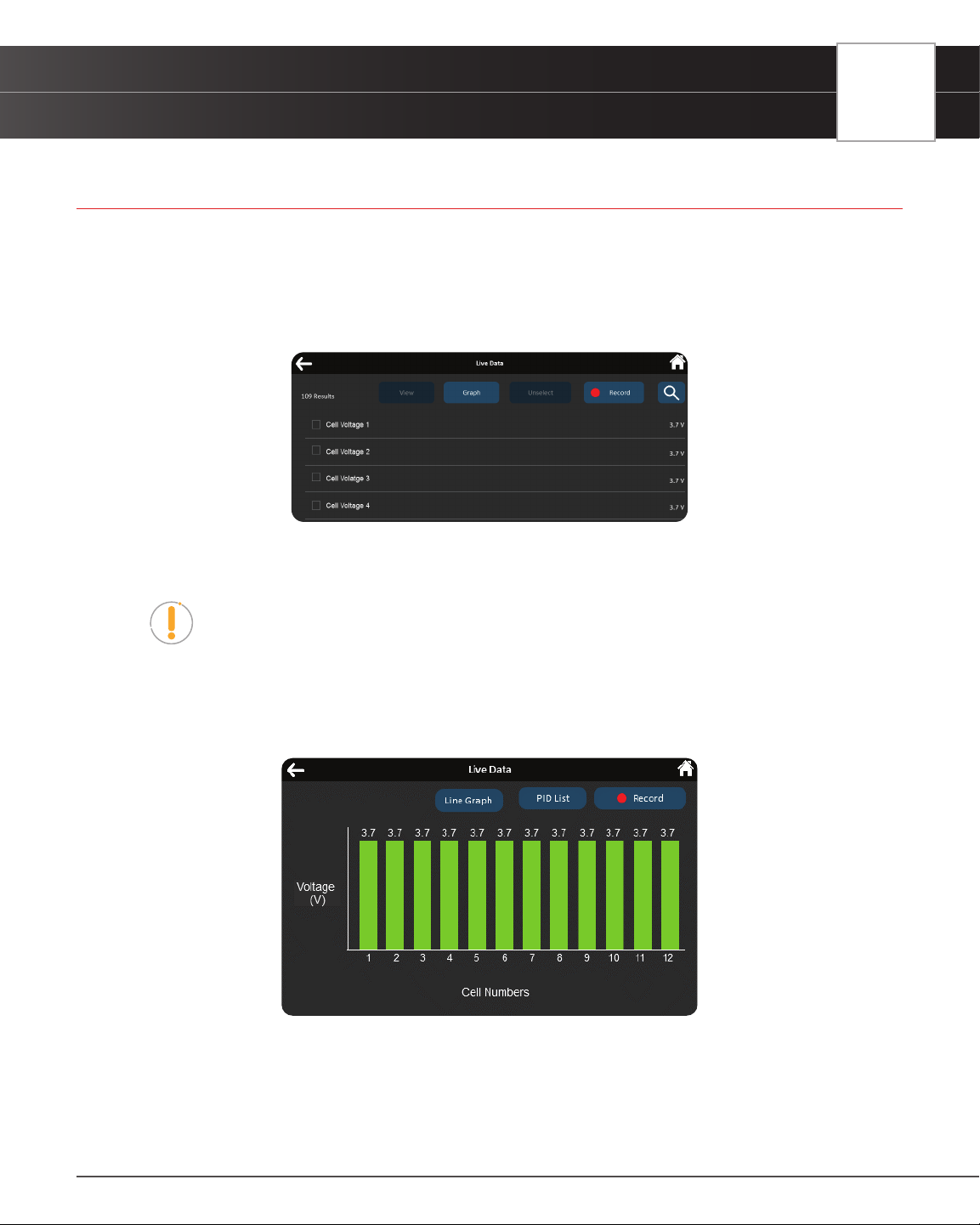
WORKSHOP TOOLS
EV / HEV / PHEV Battery Health
49
EV / HEV / PHEV BATTERY HEALTH
The tablet offers the ability to check the battery health for a variety of electric powered vehicles, including: Electric
Vehicle (EV), Hybrid-Electric Vehicle (HEV), and Plug-In Hybrid Electric Vehicle (PHEV).
1. Tap EV/HEV/PHEV Battery Health on the Workshop Tools screen.
2. The Live Data dialog page displays with corresponding PIDs.
3. Tap Graph to view all PIDs in bar graph format, or select the PIDs you wish to view and tap either the View,
Graph, or Record buttons to proceed.
NOTE: When using the Graph function, selecting more than 10 PIDs will result
with an alert dialog “Recording more than 10 PIDs may decrease frequency”. If
prompted, tap the Continue button to view the graph or Back buttons to return to
the PID values page.
4. The View button displays the selected voltage PIDs in tabular format.
5. The Graph button displays the selected PIDs in bar graph format. A voltage below recommended specs will
appear “red” in color on the bar graph.
6. The Line Graph button displays battery voltage PIDs in line graph format.
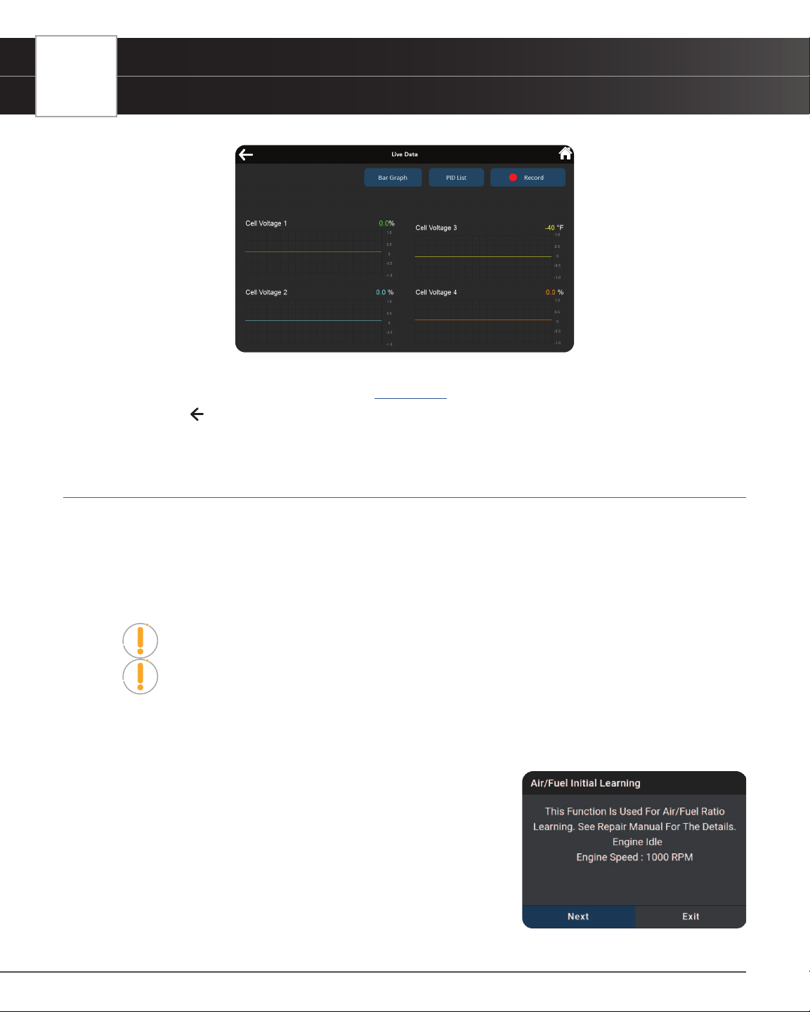
50
WORKSHOP TOOLS
A/F Setting
n The PID List button returns to the PID selection screen.
7. The Record button records selected PIDs. [See page 26]
8. Tap on the
icon at the top of the page to return to the Workshop Tools screen.
A/F SETTING
Allows you to set or re-learn new Air/Fuel ratio mix parameters.
The A/F Setting is only available for Nissan and Volvo vehicles. Procedures vary between vehicle makes and
models.
NOTE: If an error occurs while performing A/F Setting, an “advisory” message
displays. Choose Exit, as necessary, to return to the Workshop Tools screen.
NOTE: If A/F Setting is not supported for the vehicle under test, an “advisory”
message displays. Tap Exit, as necessary, to return to the Workshop Tools screen.
1. Select A/F Setting in the Workshop Tools screen.
n A “One moment please…” message may display.
n One or more sub-menus will display. Select the desired
options, then proceed to step 2.
2. One or more “informational/ instructional” screens display.
n Perform test procedures as directed. Choose Next or
Continue, as appropriate, to scroll to the next screen.
3. For some vehicles, “status” screens display as each phase of the
calibration procedure is successfully completed. Choose Next or
Continue, as appropriate, to scroll to the next screen.
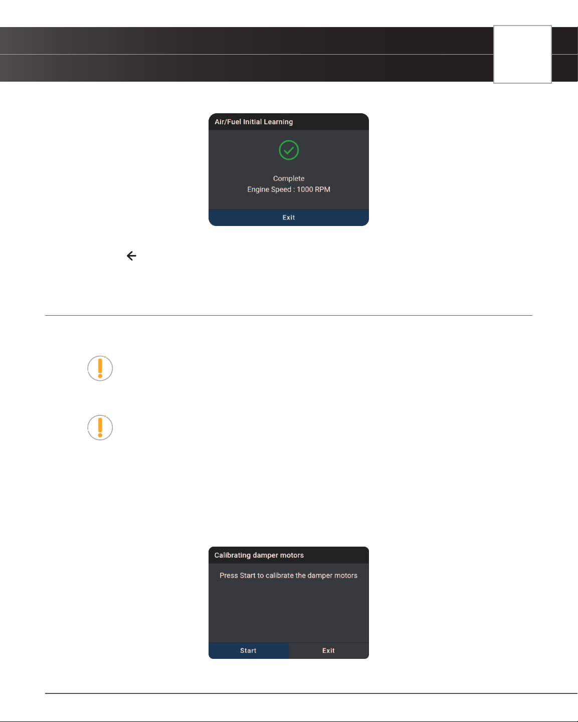
WORKSHOP TOOLS
AC System Relearn
51
n A “results” screen displays when the procedure has been completed.
4. Tap Exit to close the results message.
5. Tap on the
icon at the top of the page to return to the Workshop Tools screen.
AC SYSTEM RELEARN
Use this to re-learn the A/C equipment status after a vehicle’s PCM has been replaced.
NOTE: If an error occurs while performing AC System Relearn, an “advisory”
message displays. Choose Exit, as necessary, to return to the Workshop Tools
screen.
NOTE: If AC System Relearn is not supported for the vehicle under test, an
“advisory” message displays. Tap Exit, as necessary, to return to the Workshop
Tools screen.
1. Select AC System Relearn in the Workshop Tools screen.
n A “One moment please…” message may display.
n One or more sub-menus will display. Select the desired options, then proceed to step 2.
2. One or more “informational/ instructional” screens display.
n Choose Start, as appropriate, to perform the function.
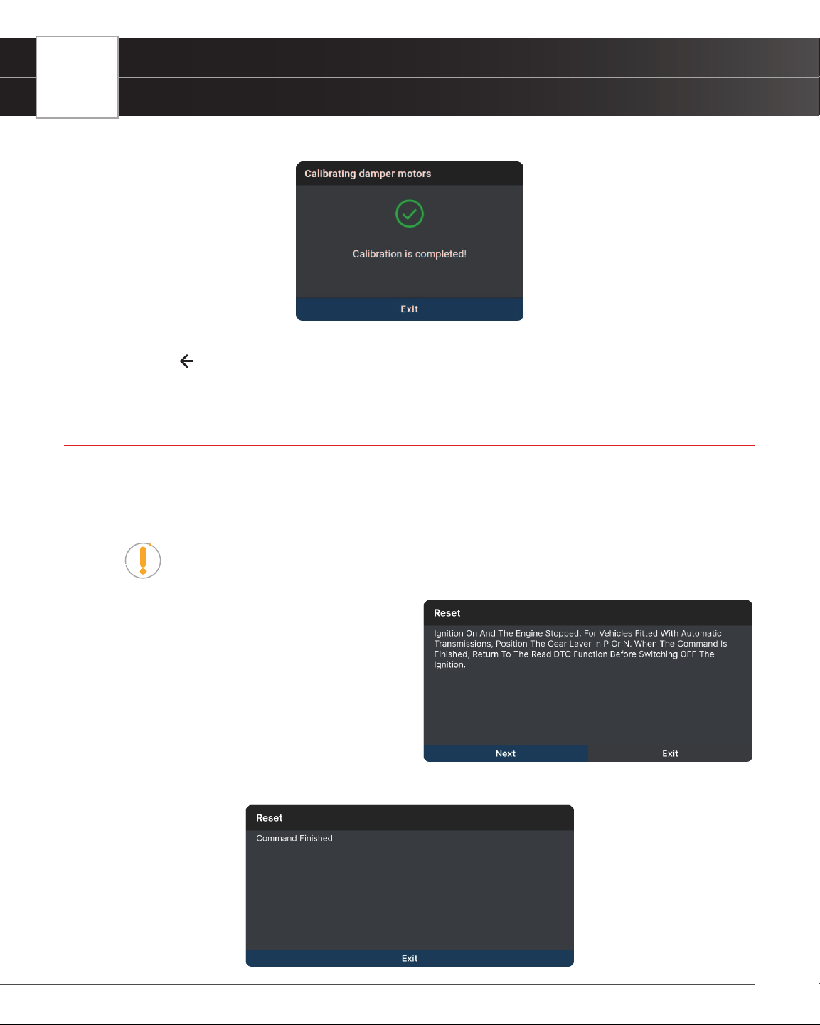
52
WORKSHOP TOOLS
Adblue Reset
3. The screen refreshes to show results.
4. Tap Exit to close the results message.
5. Tap on the
icon at the top of the page to return to the Workshop Tools screen.
ADBLUE RESET
After the diesel exhaust treatment uid is replaced or lled up, urea reset operation is required. The Adblue reset
function allows you to reset the system to the specied ll level.
1. Tap Adblue Reset on the Workshop Tools screen.
NOTE: If the Adblue Reset is not supported by the vehicle under test, an “advisory”
message displays. Tap Exit to return to the Workshop Tools screen.
n A “One moment please...” progress
dialog displays. Tap Cancel to cancel
the operation.
2. Once ready, the Adblue Reset menu will displays.
Select Reset to perform the test procedures as
directed.
3. Tap Next, as appropriate, to scroll to the next
screen. Or, tap Exit or Cancel to terminate the
procedure.
4. A “results” screen displays when the reset procedure has been completed. Tap Exit to terminate the procedure.
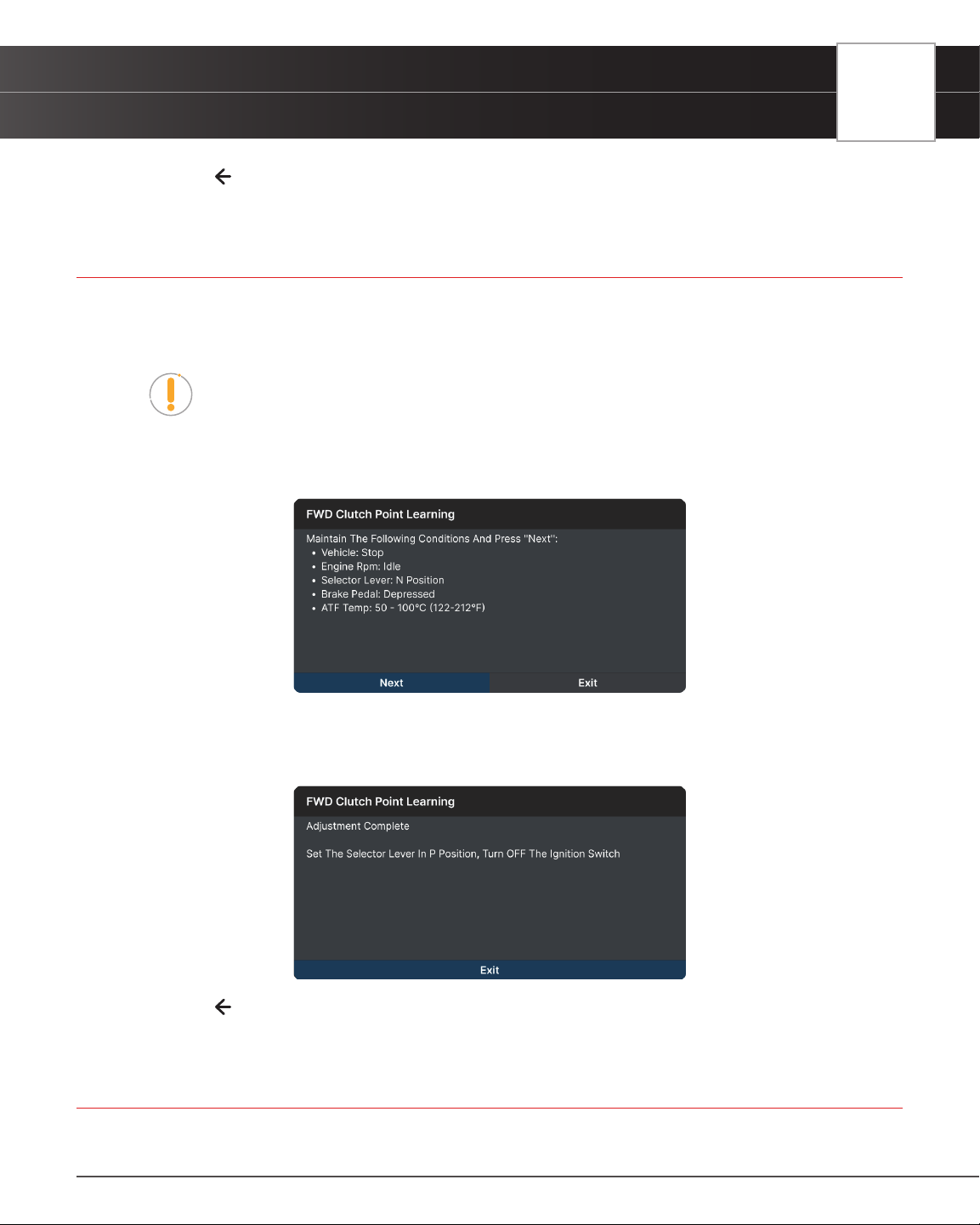
WORKSHOP TOOLS
Clutch Relearn
53
5. Tap on the icon at the top of the page to return to the Workshop Tools screen.
CLUTCH RELEARN
Use to re-learn the clutch pedal up-stop and down-stop values after an ECU or clutch pedal replacement.
1. Tap Clutch Relearn on the Workshop Tools screen.
NOTE: If the Clutch Relearn is not supported by the vehicle under test, an “advisory”
message displays. Tap Exit to return to the Workshop Tools screen.
n A “One moment please...” progress dialog displays. Tap Cancel to cancel the operation.
2. Once ready, the Clutch Relearn menu displays.
3. Select the desired option. Then perform the test procedures as directed. Tap Next or Continue, as appropriate,
to scroll to the next screen. Or, tap Exit or Cancel to terminate the procedure.
4. A “results” screen displays when the reset procedure has been completed. Tap Exit to terminate the procedure.
5. Tap on the
icon at the top of the page to return to the Workshop Tools screen.
COOLANT BLEEDING
Use this function whenever the coolant or antifreeze uids are drained and/or relled. Performing this routine removes
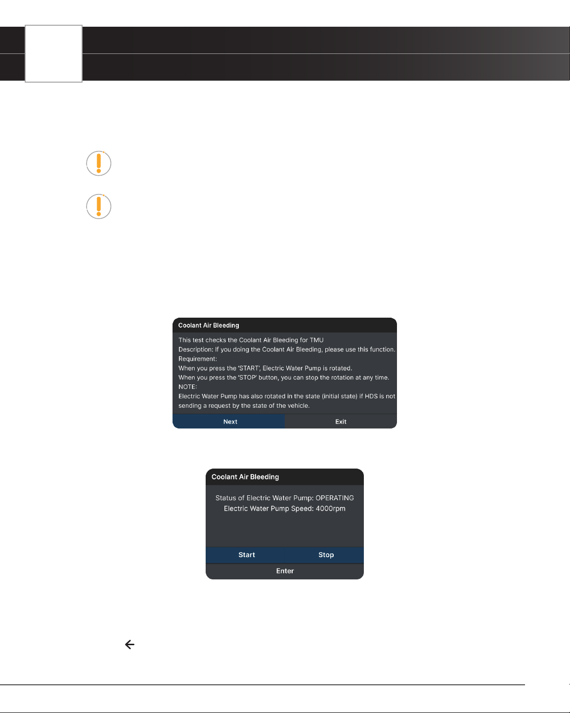
54
WORKSHOP TOOLS
Coolant Bleeding
any air pockets that may have built up when adding new coolant.
Coolant Bleeding allows activation of the electronic water pump before venting the cooling system. This
function is only available for Honda vehicles. Procedures vary between vehicle makes and models.
NOTE: If an error occurs while performing Coolant Bleeding, an “advisory” message
displays. Choose Exit, as necessary, to return to the Workshop Tools screen.
NOTE: If Coolant Bleeding is not supported for the vehicle under test, an “advisory”
message displays. Tap Exit, as necessary, to return to the Workshop Tools screen.
1. Select Coolant Bleeding in the Workshop Tools screen.
n A “One moment please…” message may display.
n One or more sub-menus will display. Select the desired options, then proceed to step 2.
2. One or more “informational/ instructional” screens display.
n Perform test procedures as directed. Choose Next, as appropriate, to scroll to the next screen.
3. Tap Start or Stop as desired.
n The screen is refreshed to show the result.
4. Tap Enter to nish the function.
n One or more “instructional” screens will display. Follow the instructions on the screen.
5. Tap Exit to close the results message.
6. Tap on the
icon at the top of the page to return to the Workshop Tools screen.
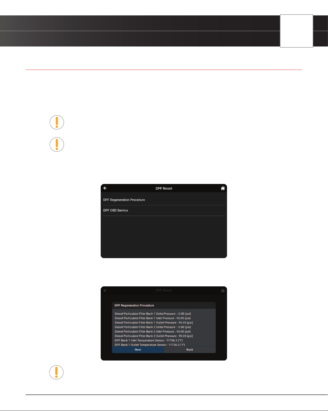
WORKSHOP TOOLS
DPF Reset
55
DPF RESET
Use this function to initialize the regeneration of the vehicle’s diesel particulate lter, or DPF, to prevent it from causing
damage because of stuck of soot and ash in the vehicle’s exhaust system. It also initializes the sensor and DPF
component after they are replaced, when the DPF warning light came on, or when replacing the DPF pressure sensor.
1. Tap DPF Reset on the Workshop Tools screen.
NOTE: If the DPF Reset is not supported by the vehicle under test, an “advisory”
message displays. Tap Exit to return to the Workshop Tools screen.
NOTE: The DPF Reset is only performed on Diesel vehicle.
n An “instructional” dialog displays to conrm selection. Select Yes to continue. Or, No to cancel.
n A “One moment please...” progress dialog displays.
2. The DPF Reset menu displays, select the desired option.
3. Tap the DPF Regeneration Procedure.
n The DPF Regeneration Procedure screen displays.
NOTE: If the vehicle under test does not support DPF Regeneration Procedure,
an “information” screen displays the procedures for “passive” DPF regeneration.
Choose Back to return to the DPF Reset menu.
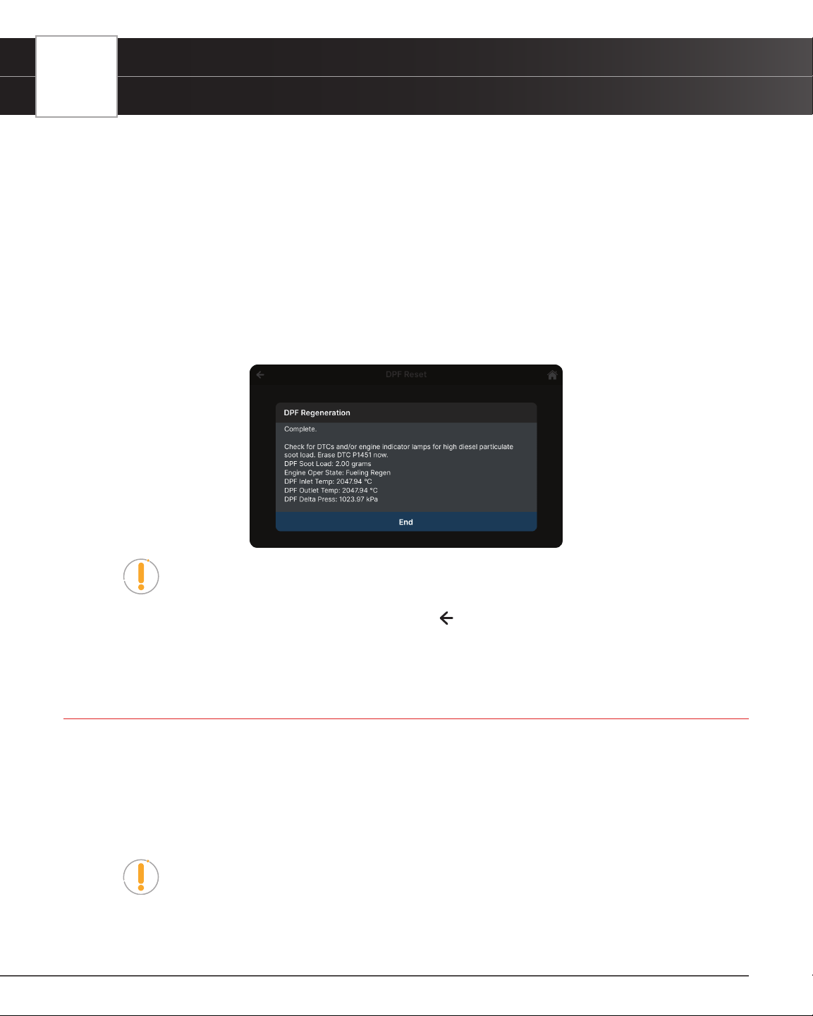
56
WORKSHOP TOOLS
Headlamp Calibration
4. Choose Next to continue.
n An “informational” screen displays the procedures for “passive” or “active” DPF regeneration,
as applicable. Choose Back to return to the DPF Reset Menu.
5. Tap the DPF OBD Service.
n A “One moment” message displays, followed by the Diesel Particulate Filter Reset menu. Select
the desired option.
n An “instructional” screen displays. Prepare the vehicle for test as directed.
6. Choose Next to continue.
n A series of “status” screens display while the routine is in process.
n A “conrmation” screen displays when the routine is completed.
NOTE: If the routine does not complete successfully, an “advisory” message
displays. Choose Exit to return to the DPF Reset menu.
7. Tap End to return to the DPF Reset menu, then tap on the
icon at the top of the page to return to the Workshop
Tools screen.
HEADLAMP CALIBRATION
Calibration is required in most cases after installing a new headlamp capsule or replacing the sensors and modules
used to operate the headlamps. This function allows you to adjust the ride height to the manufacturer’s recommended
specications.
This function is only available for Audi, BMW, Chrysler, Ford, GM, Hyundai-KIA, Mazda, Mercedes-Benz, Nissan,
Subaru, Toyota, Volkswagen, and Volvo vehicles. Procedures vary between vehicle makes and models.
NOTE: If an error occurs while performing Headlamp Calibration, an “advisory”
message displays. Choose Exit, as necessary, to return to the Workshop Tools
screen.
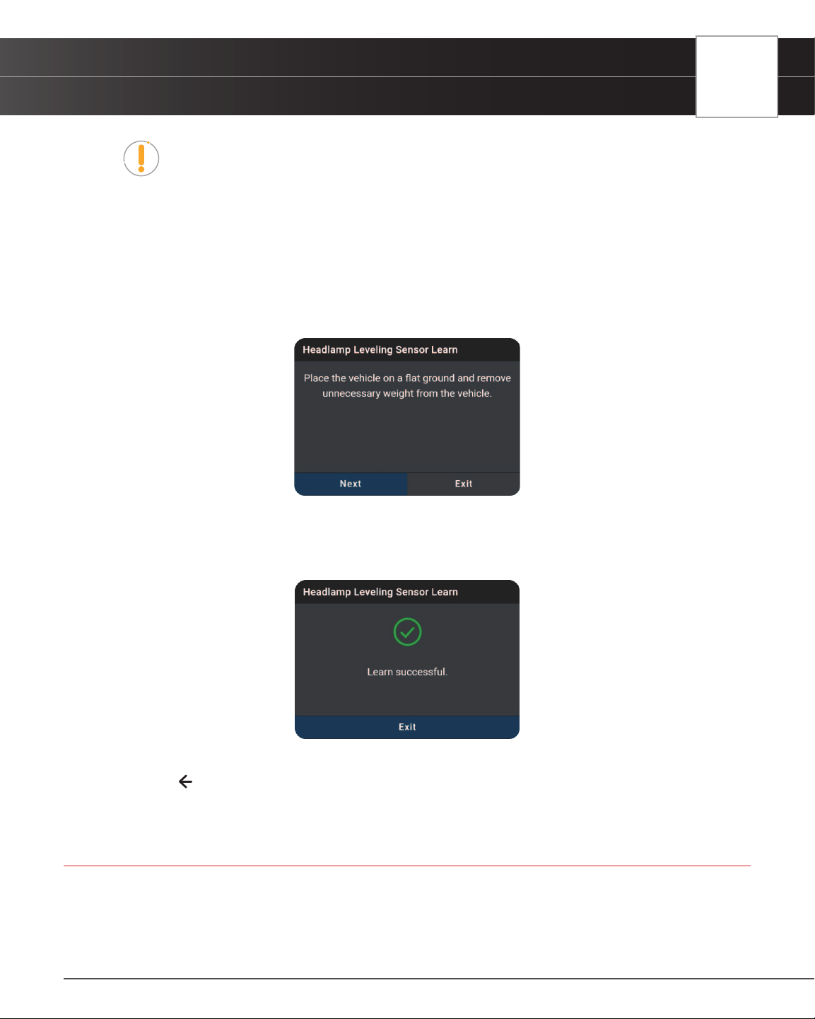
WORKSHOP TOOLS
Immobilizer Reset
57
NOTE: If Headlamp Calibration is not supported for the vehicle under test, an
“advisory” message displays. Tap Exit, as necessary, to return to the Workshop
Tools screen.
1. Select Headlamp Calibration in the Workshop Tools screen.
n A “One moment please…” message may display.
n One or more sub-menus will display. Select the desired options, then proceed to step 2.
2. One or more “informational/ instructional” screens display.
n Perform test procedures as directed. Choose Next or Continue, as appropriate, to scroll to the
next screen.
3. For some vehicles, “status” screens display as each phase of the calibration procedure is successfully completed.
Tap On, Off or Start as desired, to perform the function.
n A “results” screen displays when the procedure has been completed.
4. Tap Exit to close the results message.
5. Tap on the
icon at the top of the page to return to the Workshop Tools screen.
IMMOBILIZER RESET
Allows you to reset the ignition immobilizer after the ignition switch key, ignition switch, combined instrument panel,
ECU, BCM, or remote-control battery is replaced.
1. Tap Immobilizer Reset on the Workshop Tools screen.
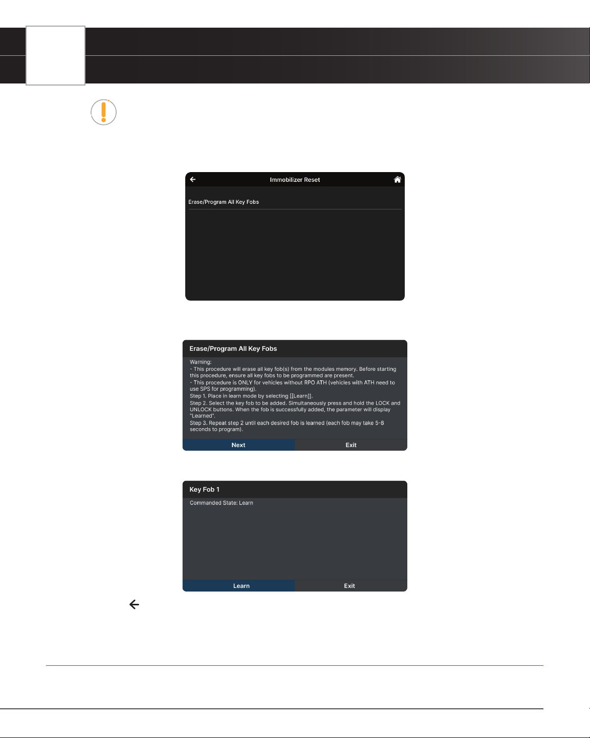
58
WORKSHOP TOOLS
Injector Coding
NOTE: If the Immobilizer Reset is not supported by the vehicle under test, an
“advisory” message displays. Tap Exit to return to the Workshop Tools screen.
n A “One moment please...” progress dialog displays. Tap Cancel to cancel the operation.
2. Once ready, the Immobilizer Reset menu displays.
3. Select the desired option. Then perform the test procedures as directed. Tap Next or Learn, as appropriate, to
scroll to the next screen. Or, tap Exit or Cancel to terminate the procedure.
4. A “results” screen displays when the reset procedure has been completed. Tap Exit to terminate the procedure.
5. Tap on the
icon at the top of the page to return to the Workshop Tools screen.
INJECTOR CODING
Sets the injector adjustment values after installing new diesel fuel injectors so it can properly communicate with the
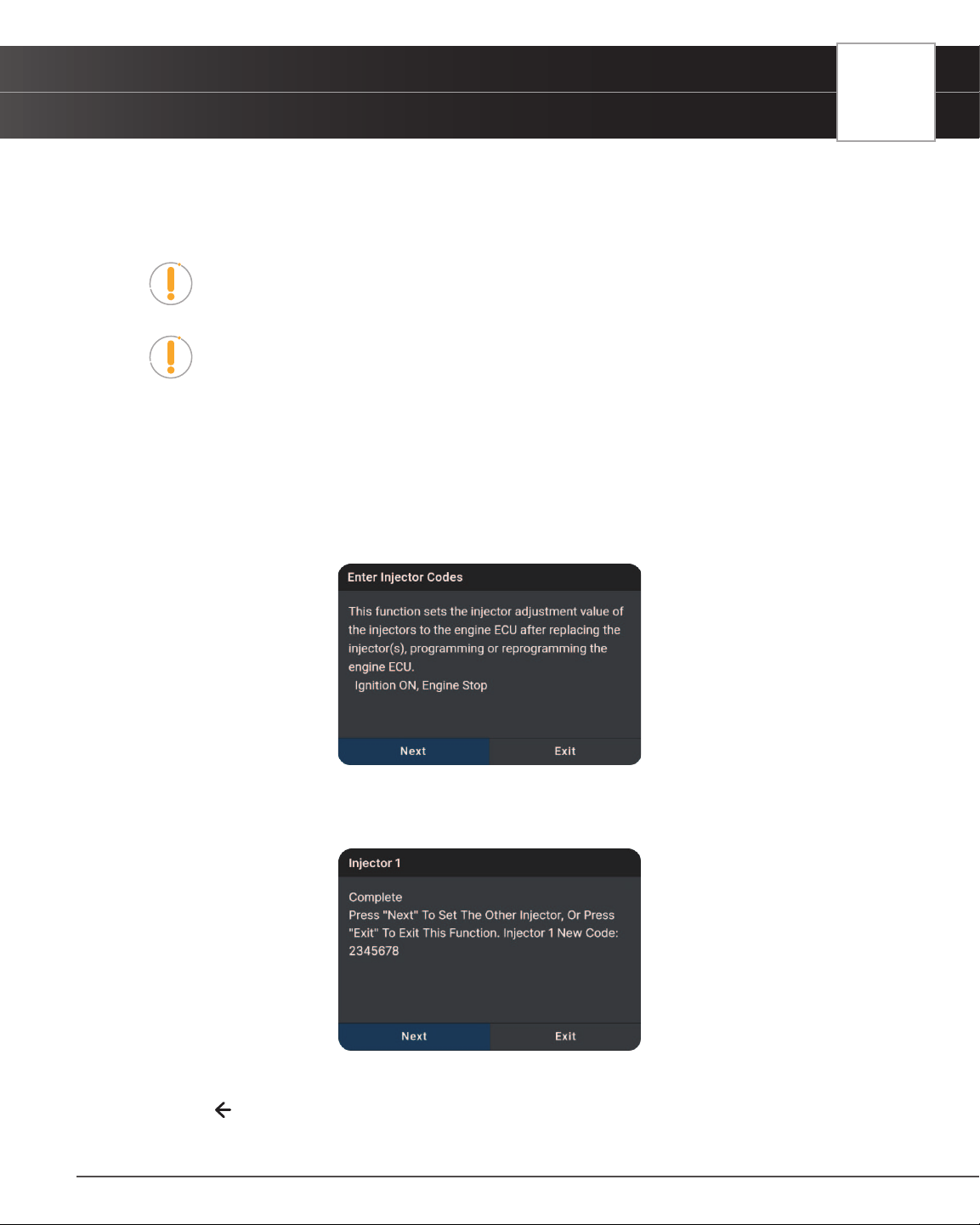
WORKSHOP TOOLS
Injector Coding
59
vehicle’s digital Electronic Control Unit, or ECU.
Only available for Audi, Chrysler, GM, Nissan, and Volkswagen vehicles. Procedures vary between vehicle
makes and models.
NOTE: If an error occurs while performing Injector Coding, an “advisory” message
displays. Choose Exit, as necessary, to return to the Workshop Tools screen.
NOTE: If Injector Coding is not supported for the vehicle under test, an “advisory”
message display. Tap Exit, as necessary, to return to the Workshop Tools screen.
1. Select Injector Coding in the Workshop Tools screen.
n A “One moment please…” message may display.
n One or more sub-menus will display. Select the desired options, then proceed to step 2.
2. One or more “informational/ instructional” screens display.
n Perform test procedures as directed. Choose Next or Continue, as appropriate, to scroll to the
next screen.
3. For some vehicles, “status” screens display as each phase of the calibration procedure is successfully completed.
Choose Next or Continue, as appropriate, to scroll to the next screen.
n A “results” screen displays when the procedure has been completed.
4. Tap Exit to close the results message.
5. Tap on the
icon at the top of the page to return to the Workshop Tools screen.
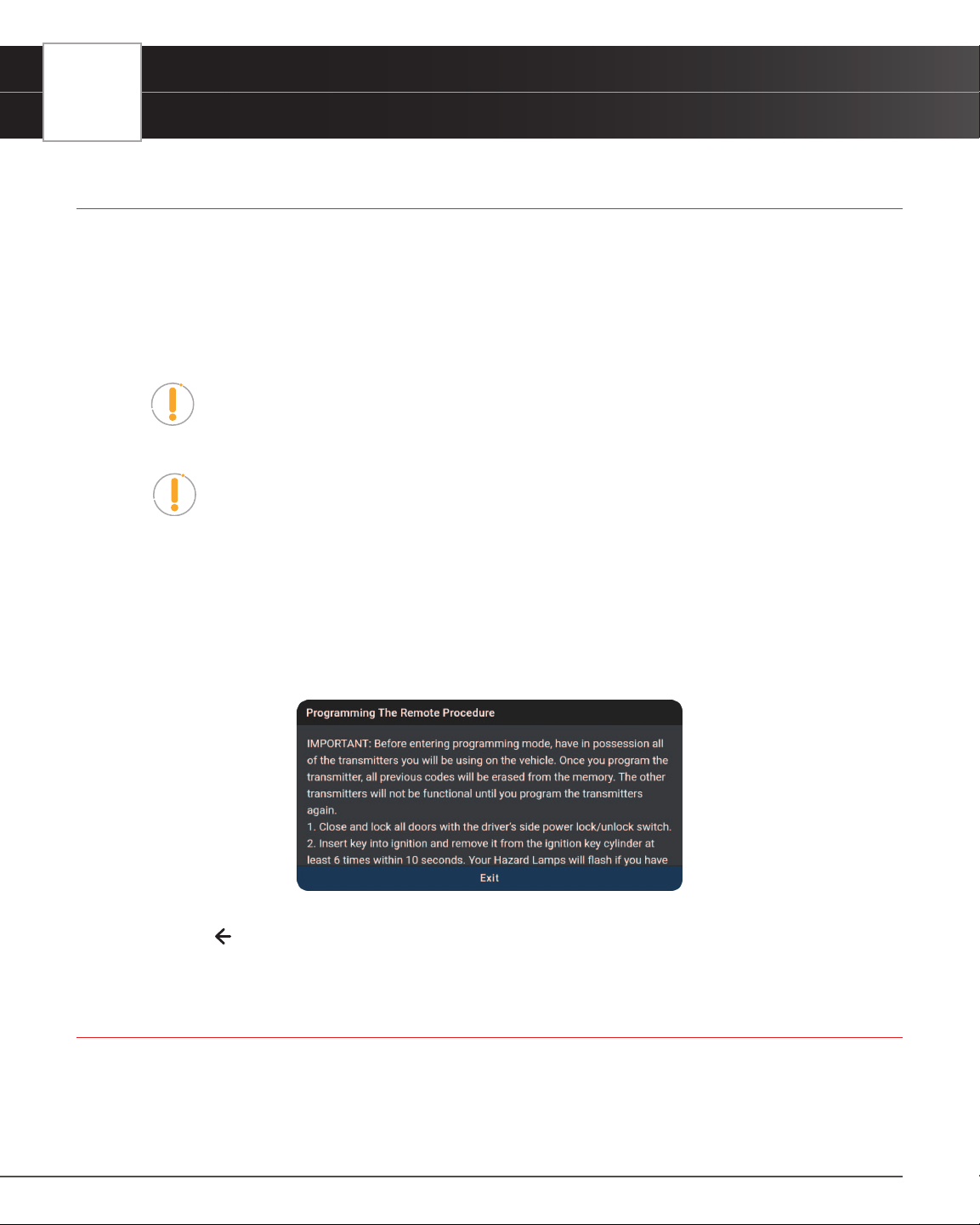
60
WORKSHOP TOOLS
Key Coding Procedure
KEY CODING PROCEDURE
Use this function to add (program) a new key fob and remotely disable a lost key – preventing the vehicle to be stolen
in the future.
The Key Coding Procedure is only available for Audi, BMW, Chrysler, Ford, GM, Jaguar/ Land Rover, Honda,
Hyundai-KIA, Mazda, Mitsubishi, Nissan, Subaru, Toyota, and Volkswagen vehicles. Procedures vary between
vehicle makes and models.
NOTE: If an error occurs while performing Key Coding Procedure, an “advisory”
message display. Choose Exit, as necessary, to return to the Workshop Tools
screen.
NOTE: If Key Coding Procedure is not supported for the vehicle under test, an
“advisory” message display. Tap Exit, as necessary, to return to the Workshop Tools
screen.
1. Select Key Coding Procedure in the Workshop Tools screen.
n A “One moment please…” message may display.
n The Key Coding Procedure menu displays.
2. Tap the procedure you wish to view.
n The screen shows the procedure for the option you selected.
3. Tap Exit to close the results screen.
4. Tap on the
icon at the top of the page to return to the Workshop Tools screen.
LANGUAGE CHANGE RESET
Allows changing the displayed language of the cabin compartment or update the language displayed in the cluster.
1. Tap Language Change Reset on the Workshop Tools screen.
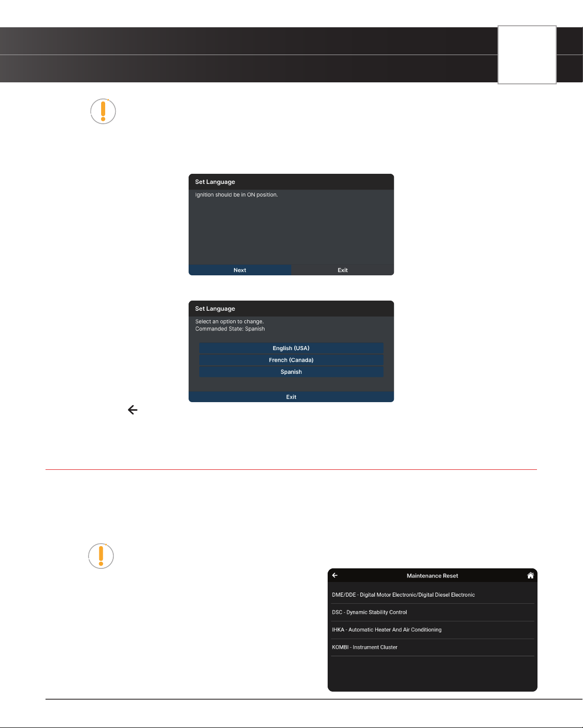
WORKSHOP TOOLS
Maintenance Reset
61
NOTE: If the Language Change Reset is not supported by the vehicle under test, an
“advisory” message displays. Tap Exit to return to the Workshop Tools screen.
n A “One moment please...” progress dialog displays. Tap Cancel to cancel the operation.
2. Once ready, the Language Change Reset menu displays.
3. Select the desired language. Tap Exit to terminate the procedure.
4. Tap on the
icon at the top of the page to return to the Workshop Tools screen.
MAINTENANCE RESET
The Maintenance Reset function gives you access to view the procedures, or send a command, for resetting the
scheduled maintenance counter to zero after servicing the vehicle.
1. Tap Maintenance Reset on the Workshop Tools screen.
NOTE: If the Maintenance Reset is not supported by the vehicle under test, an
“advisory” message displays. Tap Exit to return to the Workshop Tools screen.
n A “One moment please...” progress dialog
displays. Tap Cancel to cancel the operation.
2. Once ready, the Maintenance Reset menu displays.
n Select the desired option. Then perform the
test procedures as directed. Tap Next, as
appropriate, to scroll to the next screen. Or, tap
Exit or Cancel to terminate the procedure.
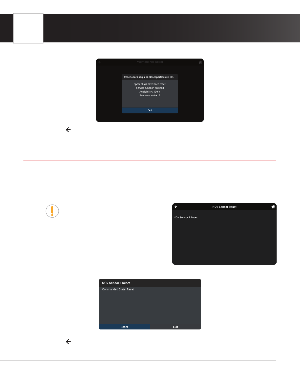
62
WORKSHOP TOOLS
NOx Sensor Reset
3. A “results” screen displays when the reset procedure has been completed. Tap End to terminate the procedure.
4. Tap on the icon at the top of the page to return to the Workshop Tools screen.
NOX SENSOR RESET
NOx sensor helps detect the content of nitrogen oxides (NOx) within the engine’s exhaust. Use this function to reset
the catalytic converter correct values in the vehicle’s Electronic Control Unit (or ECU) whenever a NOx fault is re-
initialized and the NOx catalytic converter is replaced.
1. Tap NOx Sensor Reset on the Workshop Tools screen.
NOTE: If the NOx Sensor Reset is not supported
by the vehicle under test, an “advisory” message
displays. Tap Exit to return to the Workshop
Tools screen.
n A “One moment please...” progress dialog
displays. Tap Cancel to cancel the operation.
2. Once ready, the NOx Sensor Reset menu displays.
3. Select the desired option. Tap Reset to perform reset NOx
sensor selected. Or, tap Exit to return to the NOx Sensor
Reset menu.
4. Tap on the
icon at the top of the page to return to the Workshop Tools screen
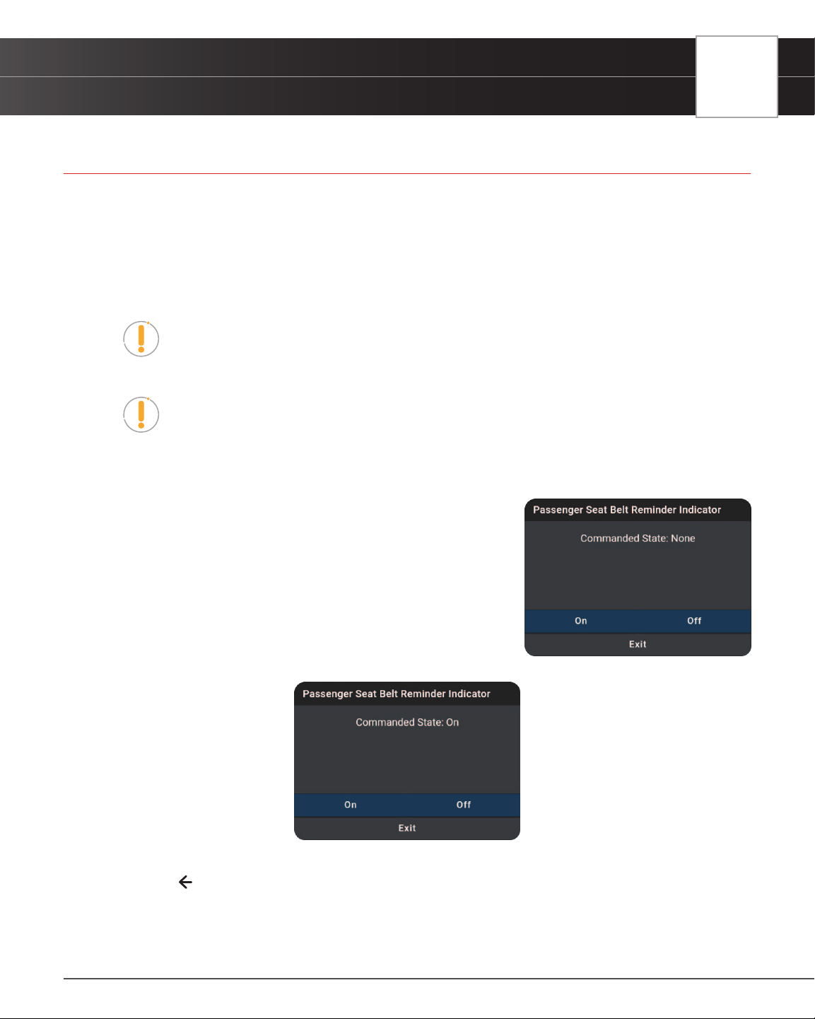
WORKSHOP TOOLS
Occupant Seat Sensor Calibration
63
OCCUPANT SEAT SENSOR CALIBRATION
Use this to reset or calibrate the vehicle’s seat sensors after making repairs after an accident or seat service routine.
This feature helps set the zero point for the passenger seat.
The Occupant Seat Sensor Calibration is only available for Audi, BMW, Chrysler, Ford, GM, Hyundai-KIA, Honda,
Mazda, Mitsubishi, Nissan, Subaru, Toyota, Volkswagen, and Volvo vehicles. Procedures vary between vehicle
makes and models.
NOTE: If an error occurs while performing Occupant Seat Sensor Calibration, an
“advisory” message displays. Choose Exit, as necessary, to return to the Workshop
Tools screen.
NOTE: If Occupant Seat Sensor Calibration is not supported for the vehicle under
test, an “advisory” message displays. Tap Exit, as necessary, to return to the
Workshop Tools screen.
1. Select Occupant Seat Sensor Calibration in the Workshop Tools screen.
n A “One moment please…” message may display.
n One or more sub-menus will display. Select the desired
options, then proceed to step 2.
2. One or more “informational/ instructional” screens display.
n Perform test procedures as directed. Select On or Off, as
appropriate.
3. For some vehicles, “status” screens display as each phase of the
calibration procedure is successfully completed.
n The screen is refreshed to show the result.
4. Tap Exit to close the results message.
5. Tap on the
icon at the top of the page to return to the Workshop Tools screen.
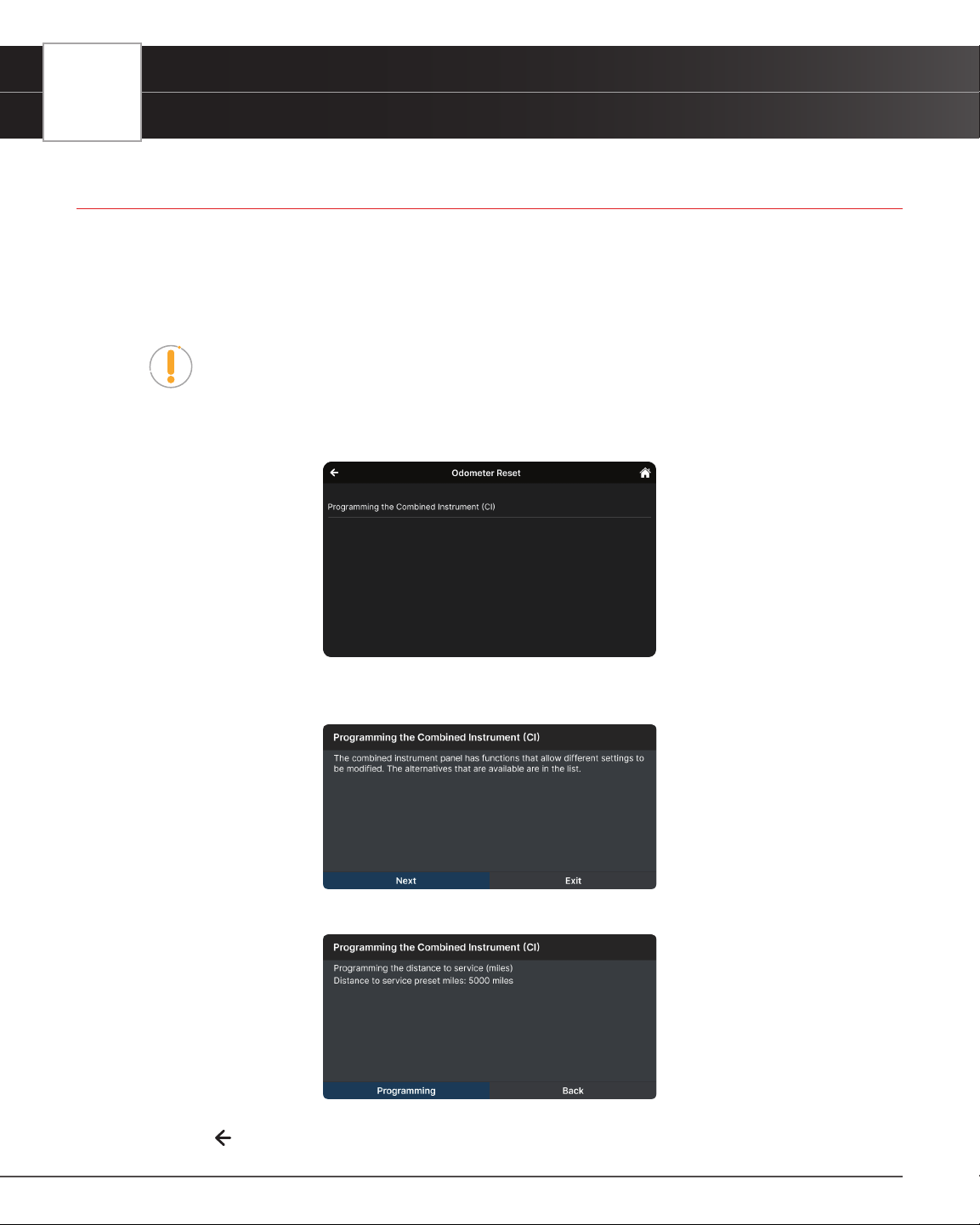
64
WORKSHOP TOOLS
Odometer Reset
ODOMETER RESET
When the mileage is not correct due to a damaged vehicle speed sensor or odometer failure, it is necessary to perform
an odometer reset after repairs. Use this function to copy, write, or rewrite the miles/kilometers back to the legally
correct mileage in the vehicle’s odometer chip.
1. Tap Odometer Reset on the Workshop Tools screen.
NOTE: If the Odometer Reset is not supported by the vehicle under test, an
“advisory” message displays. Tap Exit to return to the Workshop Tools screen.
n A “One moment please...” progress dialog displays. Tap Cancel to cancel the operation.
2. Once ready, the Odometer Reset menu displays.
3. Select the desired option. Then perform the test procedures as directed. Tap Next or Programming, as appropriate,
to scroll to the next screen. Or, tap Exit or Cancel to terminate the procedure.
4. A “results” screen displays when the reset procedure has been completed. Tap Back to terminate the procedure.
5. Tap on the
icon at the top of the page to return to the Workshop Tools screen.
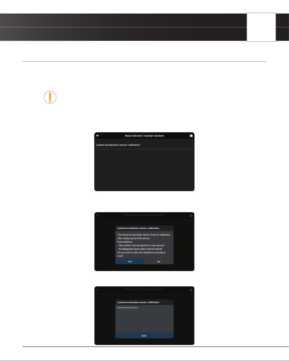
WORKSHOP TOOLS
Reset Electric Traction System
65
RESET ELECTRIC TRACTION SYSTEM
Use this feature to calibrate the Yaw Rate Sensor after replacement of the ABS ECU and Yaw Rate / G sensor.
1. Tap Reset Electric Traction System on the Workshop Tools screen.
NOTE: If the Reset Electric Traction System is not supported by the vehicle under
test, an “advisory” message displays. Tap Exit to return to the Workshop Tools
screen.
n A “One moment please...” progress dialog displays. Tap Cancel to cancel the operation.
2. Once ready, the Reset Electric Traction System menu displays.
3. Select the desired option. Then perform the test procedures as directed. Tap Yes or Continue, as appropriate,
to scroll to the next screen. Or, tap No/Exit or Cancel to terminate the procedure.
4. A “results” screen displays when the reset procedure has been completed. Tap Exit to terminate the procedure.
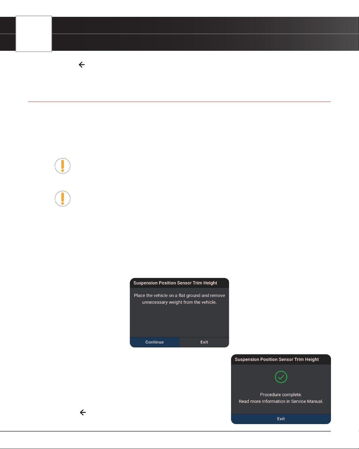
66
WORKSHOP TOOLS
Suspension Calibration
5. Tap on the icon at the top of the page to return to the Workshop Tools screen.
SUSPENSION CALIBRATION
Use this function to reset the height for the vehicle’s 4 suspensions on each wheel when the heights are different, or
after replacing the vehicle height sensor or control module in the vehicle’s air suspension system.
Suspension Calibration is only available for Audi, BMW, Chrysler, GM, Mercedes-Benz, Nissan, Toyota, and
Volkswagen vehicles. Procedures vary between vehicle makes and models.
NOTE: If an error occurs while performing Suspension Calibration, an “advisory”
message displays. Choose Exit, as necessary, to return to the Workshop Tools
screen.
NOTE: If Suspension Calibration is not supported for the vehicle under test, an
“advisory” message displays. Tap Exit, as necessary, to return to the Workshop
Tools screen.
1. Select Suspension Calibration in the Workshop Tools screen.
n A “One moment please…” message may display.
n One or more sub-menus will display. Select the desired options, then proceed to step 2.
2. One or more “informational/ instructional” screens display.
n Perform test procedures as directed. Choose Next or Continue, as appropriate, to scroll to the
next screen.
3. For some vehicles, “status” screens display as each phase of the
calibration procedure is successfully completed. Choose Next or
Continue, as appropriate, to scroll to the next screen.
n A “results” screen displays when the procedure has been
completed.
4. Tap Exit to close the results message.
5. Tap on the
icon at the top of the page to return to the Workshop
Tools screen.
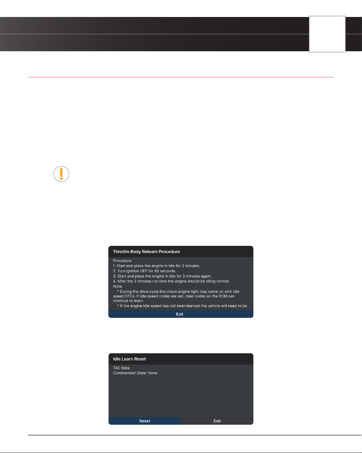
WORKSHOP TOOLS
Throttle Body Relearn/TEC Learn
67
THROTTLE BODY RELEARN/TEC LEARN
Today’s modern vehicles are being equipped with y-by-wire electronic throttle body sensors. Over time, carbon
buildup can accumulate around the throttle plate, changing its home position. If the buildup occurs gradually, the PCM
learns the new home position. But if you clean or replace the throttle body, the PCM won’t know and will continue to
use the adaptive settings as if the carbon buildup is still there. Another instance is when your battery goes dead or you
disconnect it to work on your vehicle, the PCM will again forget its adaptive home position.
This function allows you to help the PCM relearn the new throttle position anytime the throttle body is cleaned, replaced
or disconnected. Doing so ensures that idle position of the throttle plate is kept idle within the specied range.
1. Tap Throttle Body Relearn/TEC Learn on the Workshop Tools screen.
NOTE: If the Throttle Body Relearn/TEC Learn is not supported by the vehicle under
test, an “advisory” message displays. Tap Exit to return to the Workshop Tools
screen.
n A “One moment please...” progress dialog displays. Tap Cancel to cancel the operation.
2. Once ready, the Throttle Body Relearn/TEC Learn menu displays.
3. Tap Throttle Body Relearn Procedure.
n The TPMS Relearn Procedure screen displays. Tap Exit to return to the Throttle Body Relearn/
TEC Learn menu.
4. Tap Idle Learn Reset.
n An “instructional” screen displays. Tap Reset to perform the test procedures as directed. Or,
tap Exit or Cancel to terminate the procedure.
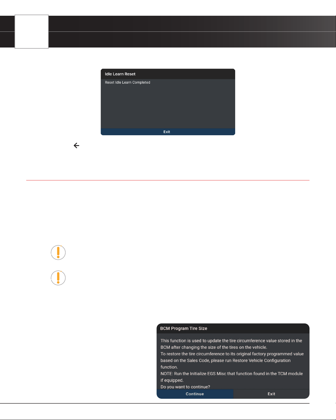
68
WORKSHOP TOOLS
Tire Size Reset
5. A “results” screen displays when the reset procedure has been completed. Tap Exit to terminate the procedure.
6. Tap on the icon at the top of the page to return to the Workshop Tools screen.
TIRE SIZE RESET
Whenever different size tires are installed on a vehicle the speedometer will no longer read the correct speed. With
larger tires, the speedometer may indicate a slower speed than in actuality; and in smaller tires, the speedometer will
indicate a faster speed. Use this function to reset the tires after installing different size tires on a vehicle.
The Tire Size Reset function is available for Chrysler, GM, and Volvo vehicles only. Procedures vary between
vehicle makes and models.
NOTE: If an error occurs while performing Tire Size Reset, an “advisory” message
display. Choose Exit, as necessary, to return to the Workshop Tools screen.
NOTE: If Tire Size Reset is not supported for the vehicle under test, an “advisory”
message display. Tap Exit, as necessary, to return to the Workshop Tools screen.
1. Select Tire Size Reset in the Workshop Tools screen.
n A “One moment please…” message may display.
n One or more sub-menus will dis-
play. Select the desired options,
then proceed to step 2.
2. One or more “informational/ instructional”
screens display.
n Perform test procedures as direct-
ed. Choose Next or Continue, as
appropriate, to scroll to the next
screen.
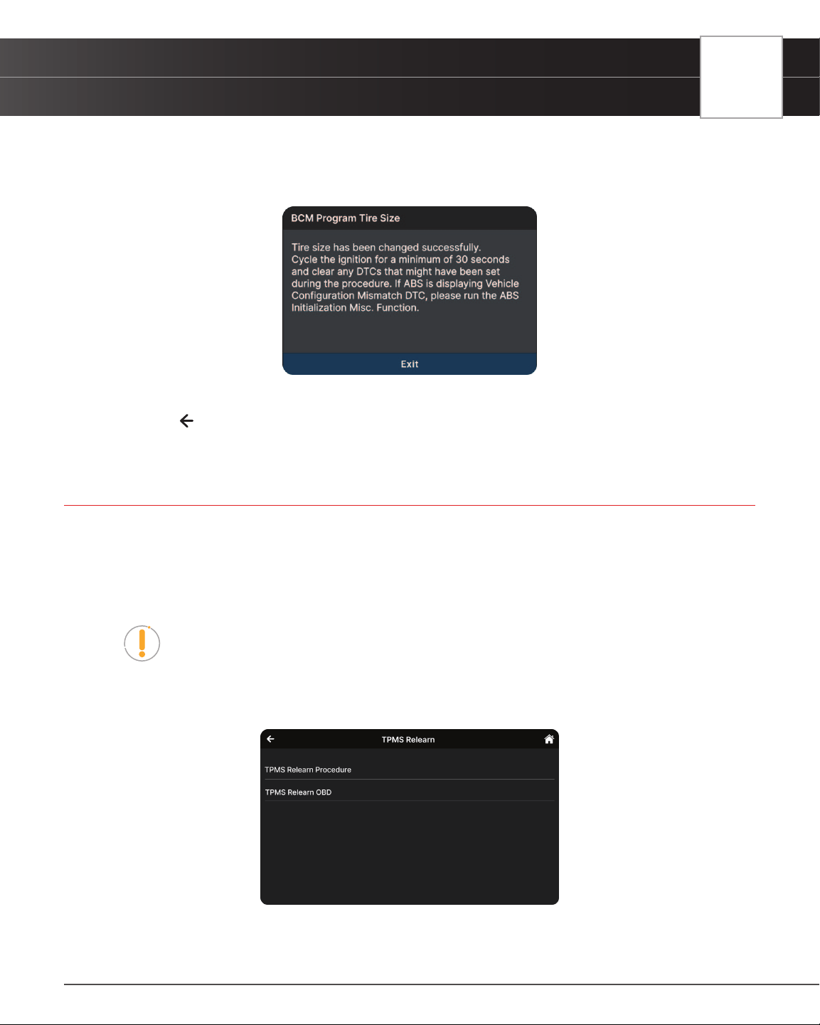
WORKSHOP TOOLS
TPMS Relearn
69
3. For some vehicles, “status” screens display as each phase of the calibration procedure is successfully completed.
Choose Next or Continue, as appropriate, to scroll to the next screen.
n A “results” screen displays when the procedure has been completed.
4. Tap Exit to close the results message.
5. Tap on the
icon at the top of the page to return to the Workshop Tools screen.
TPMS RELEARN
Use this to initialize / relearn the Tire Pressure Monitoring System, or TPMS, and turn off a TPMS light/message on the
dashboard. Also, use this function to write the ID of new sensor to the control module whenever the TPMS sensor is
replaced.
1. Tap TPMS Relearn on the Workshop Tools screen.
NOTE: If the TPMS Relearn is not supported by the vehicle under test, an “advisory”
message displays. Tap Exit to return to the Workshop Tools screen.
n A “One moment please...” progress dialog displays. Tap Cancel to cancel the operation.
2. Once ready, the TPMS Relearn menu displays.
3. Tap the TPMS Relearn Procedure.

70
WORKSHOP TOOLS
Transmission Fluid Level Check
n The TPMS Relearn Procedure screen displays. Tap Back to return to the TPMS Relearn menu.
4. Tap the TPMS Relearn OBD.
n An “instructional” screen displays. Prepare the vehicle for testing as directed.
n Select the desired option. Then perform the test procedures as directed. Tap Next or Continue,
as appropriate, to scroll to the next screen. Or, tap End or Cancel to terminate the procedure.
5. A “results” screen displays when the reset procedure has been completed. Tap End to terminate the procedure.
6. Tap on the
icon at the top of the page to return to the Workshop Tools screen.
TRANSMISSION FLUID LEVEL CHECK
Allows you to check the vehicle’s transmission uid level.
The Transmission Fluid Level Check function is available for Audi, BMW, Chrysler, GM, Mazda, and Volkswagen
vehicles only. Procedures vary between vehicle makes and models.
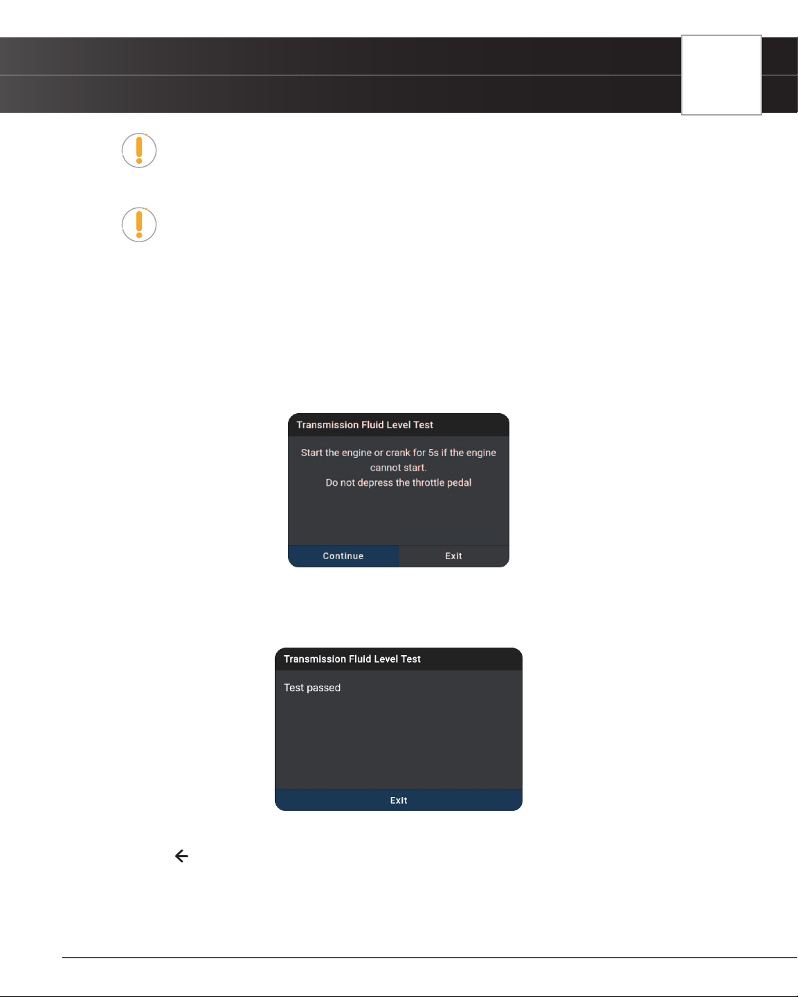
WORKSHOP TOOLS
Transmission Fluid Level Check
71
NOTE: If an error occurs while performing Transmission Fluid Level Check, an
“advisory” message displays. Choose Exit, as necessary, to return to the Workshop
Tools screen.
NOTE: If Transmission Fluid Level Check is not supported for the vehicle under test,
an “advisory” message displays. Tap Exit, as necessary, to return to the Workshop
Tools screen.
1. Select Transmission Fluid Level Check in the Workshop Tools screen.
n A “One moment please…” message may display.
n One or more sub-menus will display. Select the desired options, then proceed to step 2.
2. One or more “informational/ instructional” screens display.
n Perform test procedures as directed. Choose Next or Continue, as appropriate, to scroll to the
next screen.
3. For some vehicles, “status” screens display as each phase of the calibration procedure is successfully completed.
Choose Next or Continue, as appropriate, to scroll to the next screen.
n A “results” screen displays when the procedure has completed.
4. Tap Exit to close the results message.
5. Tap on the
icon at the top of the page to return to the Workshop Tools screen.
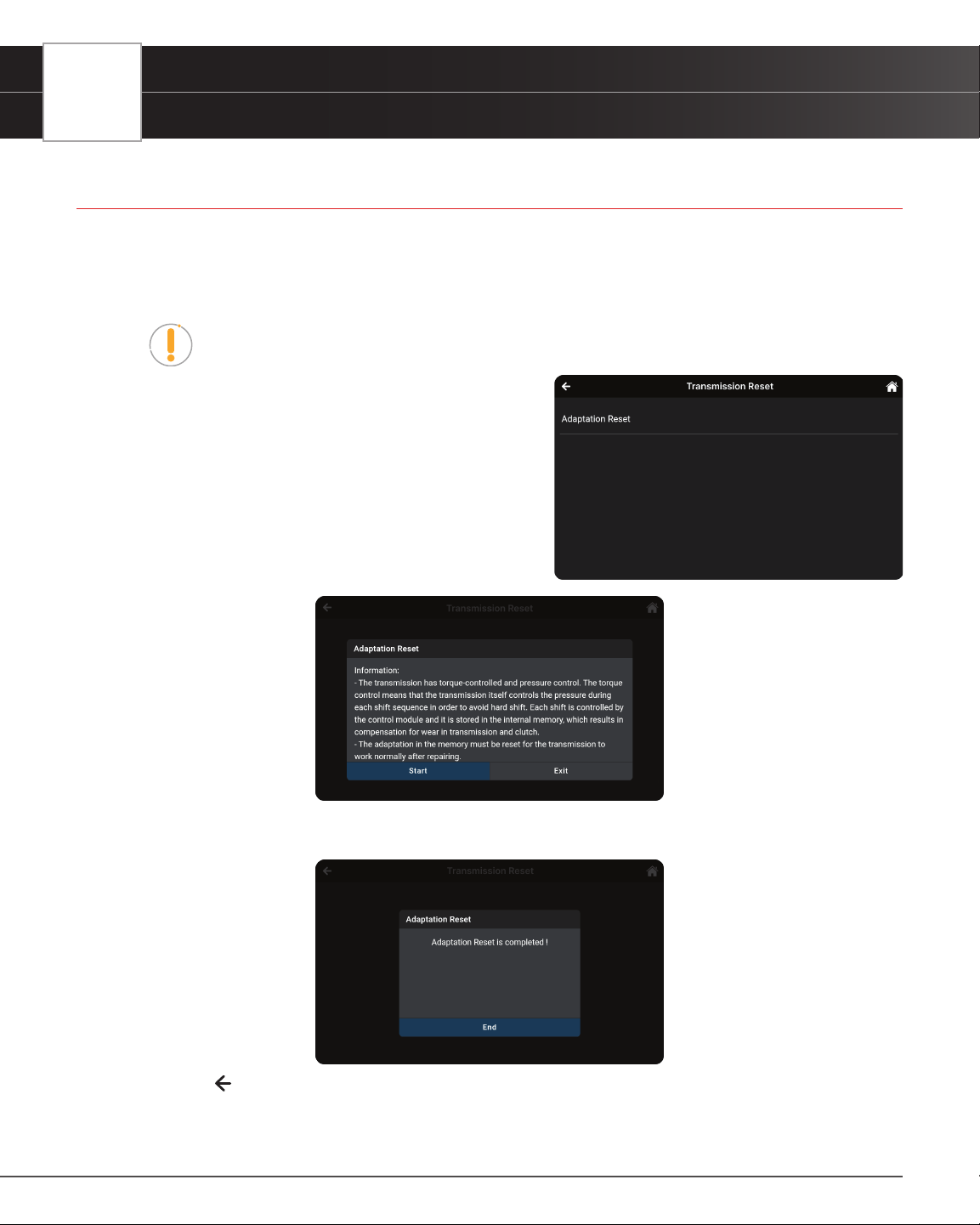
72
WORKSHOP TOOLS
Transmission Reset
TRANSMISSION RESET
When replacing the Transmission Control Module (TCM) or the Hydraulic Control Unit (HCU), use this function to reset
the vehicle’s TCM and HCU values to their default values.
1. Tap Transmission Reset on the Workshop Tools screen.
NOTE: If the Transmission Reset is not supported by the vehicle under test, an
“advisory” message displays. Tap Exit to return to the Workshop Tools screen.
n A “One moment please...” progress dialog
displays. Tap Cancel to cancel the operation.
2. Once select a module to perform Transmission Reset
function, the Transmission Reset menu will displays.
n Select the desired option. Then perform the test
procedures as directed. Tap Start or Continue,
as appropriate, to scroll to the next screen. Or,
tap Exit or Cancel to terminate the procedure.
3. A “results” screen displays when the reset procedure has been completed. Tap End to terminate the procedure.
4. Tap on the
icon at the top of the page to return to the Workshop Tools screen.
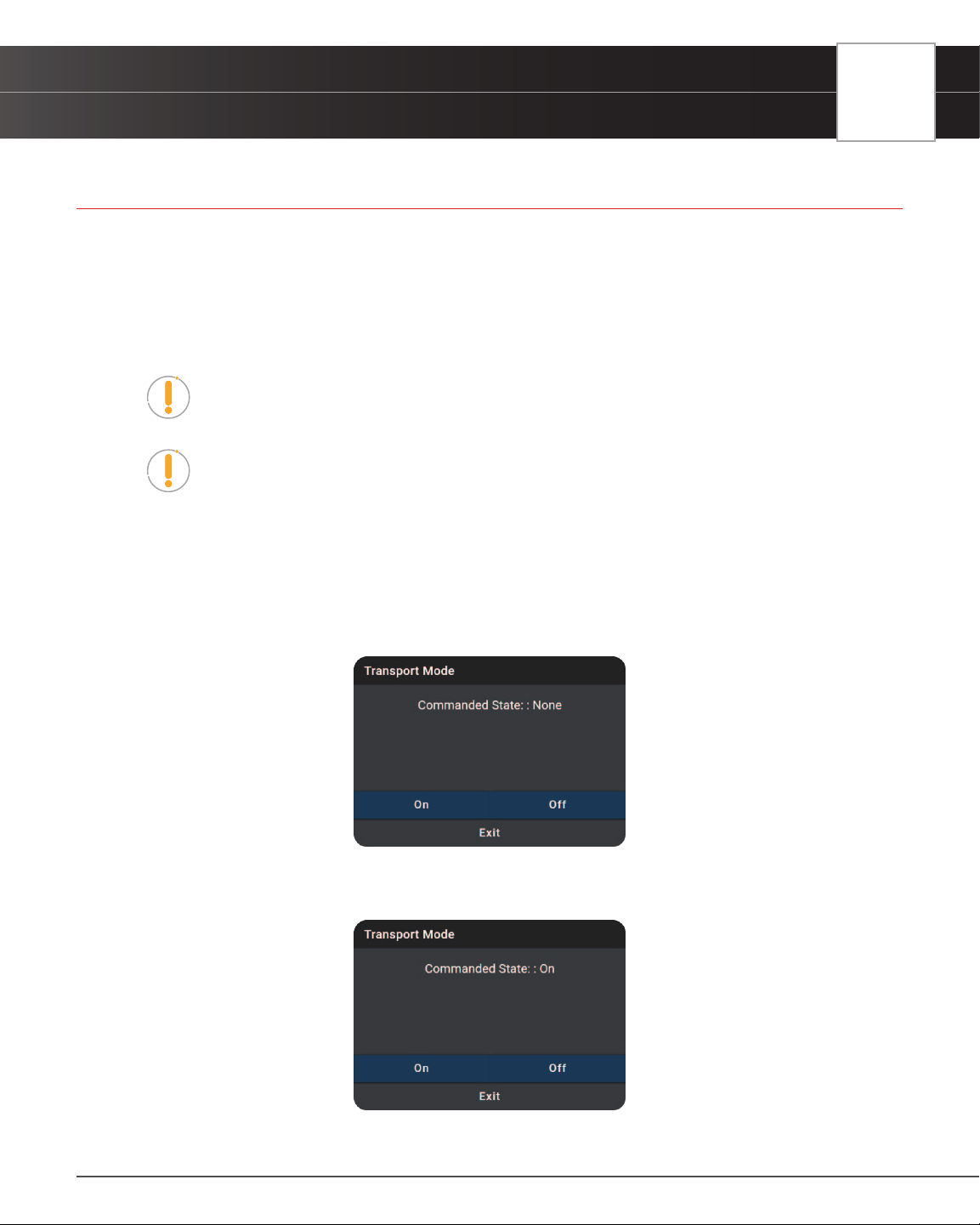
WORKSHOP TOOLS
Transport Mode
73
TRANSPORT MODE
ln order to reduce power consumption while the vehicle is in transit, the following functions may be disabled, including
limiting the vehicle speed, not waking up the door opening network, and disabling the remote-control key, etc. Use this
function to deactivate the vehicle’s transport mode to restore the vehicle to normal operation.
Transport Mode is only available for GM and Mitsubishi vehicles. Procedures vary between vehicle makes and
models.
NOTE: If an error occurs while performing Transport Mode, an “advisory” message
display. Choose Exit, as necessary, to return to the Workshop Tools screen.
NOTE: If Transport Mode is not supported for the vehicle under test, an “advisory”
message display. Tap Exit, as necessary, to return to the Workshop Tools screen.
1. Select Transport Mode in the Workshop Tools screen.
n A “One moment please…” message may display.
n One or more sub-menus will display. Select the desired options, then proceed to step 2.
2. One or more “informational/ instructional” screens display.
n Perform test procedures as directed. Select On or Off, as appropriate.
3. For some vehicles, “status” screens display as each phase of the procedure is successfully completed.
n A “results” screen displays when the procedure has been completed.
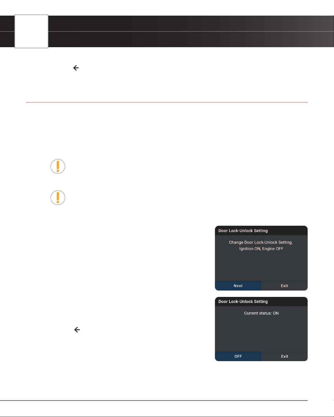
74
WORKSHOP TOOLS
Window Door Roof
4. Tap Exit to close the results message.
5. Tap on the
icon at the top of the page to return to the Workshop Tools screen.
WINDOW DOOR ROOF
With this function, you can reset the zero point (stop point) for the window, door, or sunroof sensors after being
replaced or serviced. This function can also set the sunroof to be locked off, close when it rains, the memory function
of the sliding/tilting sunroof, the outside temperature threshold, etc.
Window Door Roof is only available for BMW, Chrysler, Ford, GM, Honda, Hyundai-KIA, Nissan, Subaru, Toyota,
and Volvo vehicles. Procedures vary between vehicle makes and models.
NOTE: If an error occurs while performing Window Door Roof, an “advisory”
message display. Choose Exit, as necessary, to return to the Workshop Tools
screen.
NOTE: If Window Door Roof is not supported for the vehicle under test, an “advisory”
message display. Tap Exit, as necessary, to return to the Workshop Tools screen.
1. Select Window Door Roof in the Workshop Tools screen.
n A “One moment please…” message may display.
n One or more sub-menus will display. Select the desired
options, then proceed to step 2.
2. One or more “informational/ instructional” screens display.
n Perform test procedures as directed. Choose Next or
Continue, as appropriate, to scroll to the next screen.
3. For some vehicles, “status” screens display as each phase of the
calibration procedure is successfully completed. Choose Next or
Continue, as appropriate, to scroll to the next screen.
n A “results” screen displays when the procedure has been
completed.
4. Tap Exit to close the results message.
5. Tap on the
icon at the top of the page to return to the Workshop
Tools screen.
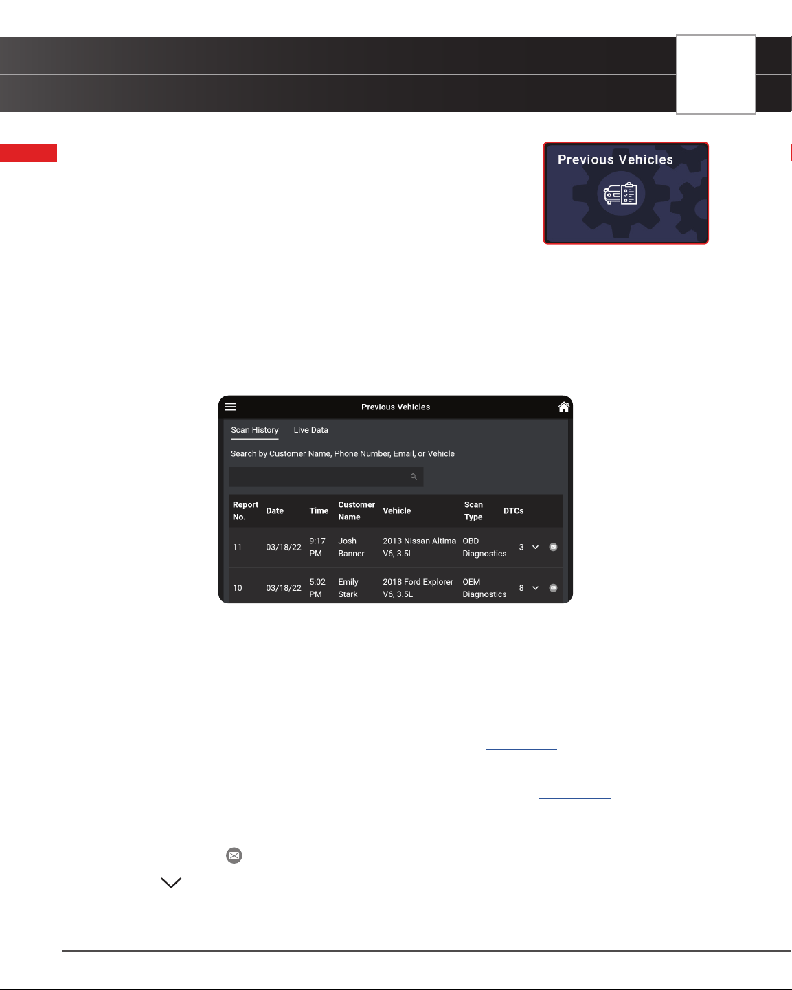
PREVIOUS VEHICLES
Scan History Reports
75
PREVIOUS VEHICLES
The INNOVA
®
Smart Diagnostic System permanently stores the results of the
most recent vehicle scans you have performed. The PREVIOUS VEHICLES
tab allows you to retrieve these historical scan records and view them as
needed. The page includes two options: Scan History and Live Data.
SCAN HISTORY REPORTS
Entries on the Scan History tab are listed in reverse chronological order (most recent scan rst). Each entry in the list
provides the following information:
n Search Bar – Tap the search bar to enter a search criterion – Customer Name, Phone Number,
Email or Vehicle.
n Report No. – The auto-generated reference report number for the scan.
n Date – The date on which the scan was performed.
n Time – The time at which the scan was performed.
n Customer Name – The name of the customer, if provided [See page 28].
n Vehicle – The year, make, model, trim and engine size of the tested vehicle.
n Scan Type – Identies if the scan was an OBD Diagnostics scan [See page 15] or an OEM
Diagnostics scan [
See page 30].
n DTCs – The total number of Diagnostic Trouble Codes retrieved by the scan.
n Email Icon
– If present, allows you to email the corresponding report.
n Icon – If present, expands to show customer’s contact information.
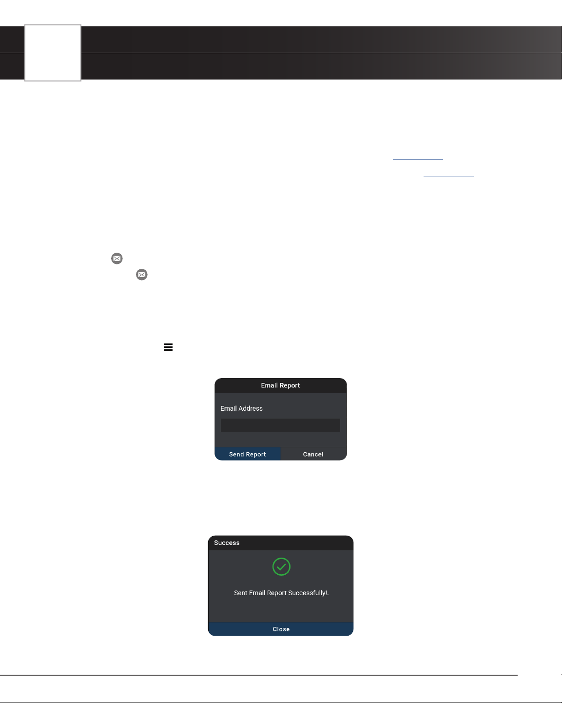
76
PREVIOUS VEHICLES
Scan History Reports
VIEWING SCAN HISTORY REPORTS
1. Tap an entry on the Scan History tab.
2. The report view differs based on the Scan Type listed on the entry:
n OBD Diagnostics – the OBD2 Diagnostic test result screen displays. [See page 15]
n OEM Diagnostics – the Vehicle Inspection Report test result screen displays. [See page 38]
n Navigate as usual to view the report.
EMAILING & PRINTING REPORTS
The Scan History report results lets you email a PDF version of the report to a customer or yourself.
1. Tap the email icon at the end of the entry.
n If the
email icon is missing:
━ Tap on the report entry you wish to send.
━ Scroll to the “Fix for DTCs” section.
━ Tap the Tap For Details button to generate the report [].
━ Tap the Menu icon and tap Previous Vehicle to return to the Scan History tab.
2. The Email Report dialog entry window displays.
3. Enter the recipient’s email address
n Be sure to use a properly formatted Email address (Example: [email protected]).
4. Tap the Send Report button to proceed; or tap Cancel to exit
n Conrmation dialog screen displays
5. Tap Close to nish and exit
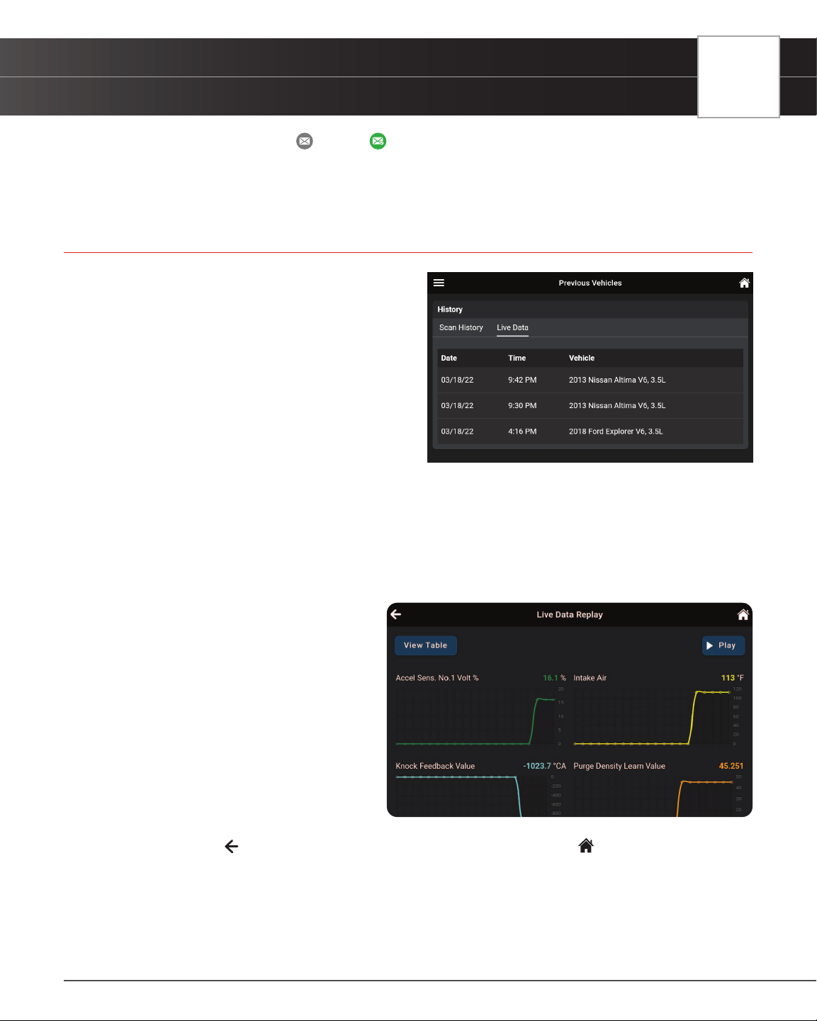
PREVIOUS VEHICLES
Playback Recorded Live Data
77
n Report icon turns from “gray” to “green” when a report is sent.
6. Recipient receives an email with a PDF copy of their report, which can be saved and printed.
PLAYBACK RECORDED LIVE DATA
Entries on the Live Data tab are listed in reverse
chronological order (most recent scan rst). Each entry in
the list provides the following information:
n Date – The date on which the recording
was made.
n Time – The time at which the recording
was made.
n Vehicle – The year, make, model and
engine size of the vehicle for which the
recording was made.
To View & Playback Recorded Live Data:
1. Tap on Live Data tab to view all recoded entries.
2. Tap an entry on the Live Data tab to play back recorded data.
n Loading Live data dialog displays
3. Tap Play to start the playback.
n If desired, use the View Table and
View Graph buttons to toggle the
display between graph mode and
tabular mode during playback.
n In the View Table mode, tap on
Unselect Parameters to unselect
all mode parameters, or tap on each
individual parameter to “select”
and “unselect” each parameter
you wish to view during playback.
4. Tap Pause to pause the playback.
5. Tap Stop to stop the playback.
6. To exit, tap on the
icon to return to the Previous Vehicle main screen, or the Home icon to return to the
Home screen.
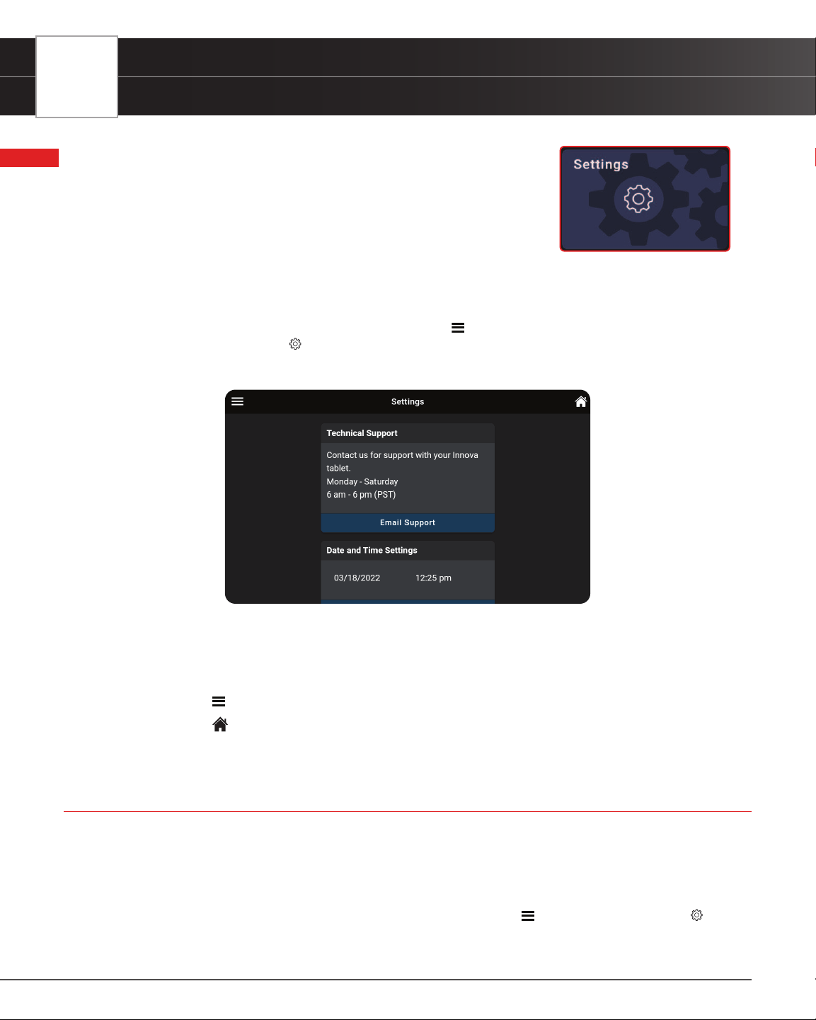
78
SETTINGS
Technical Support (Send an Email)
SETTINGS
The SETTINGS tab allows you to customize several personal preferences
including date and time, retailer selection, Wi-Fi, language, and other options.
In addition, you can contact technical support, report any issues, and search
for the vehicle’s Data Link Connector (DLC) location.
To enter the Settings mode:
1. Tap the SETTINGS tab on the Home page to access the selection page.
n You can also access this page by tapping on the
Menu icon in the upper left corner of the
page and tapping on
Settings.
n The Settings page displays.
2. Swipe up or down to scroll to the desired option.
3. Make adjustments and settings as outlined in the next pages.
To exit the Settings mode:
n Tap the
Menu icon on the top left to open the Menu panel and make another selection, or
n Tap the Home icon on the top right to return to the Home page.
TECHNICAL SUPPORT (Send an Email)
The Innova Electronics technical team is here to help if you encounter any issues or if you have any questions. You can
reach them directly with the tablet from Monday through Saturday, 6:00AM to 6:00PM, Pacic Time.
To connect with Technical Support:
1. From the Home page, tap SETTINGS. (You can also access it from the Main Menu by tapping on
Settings)
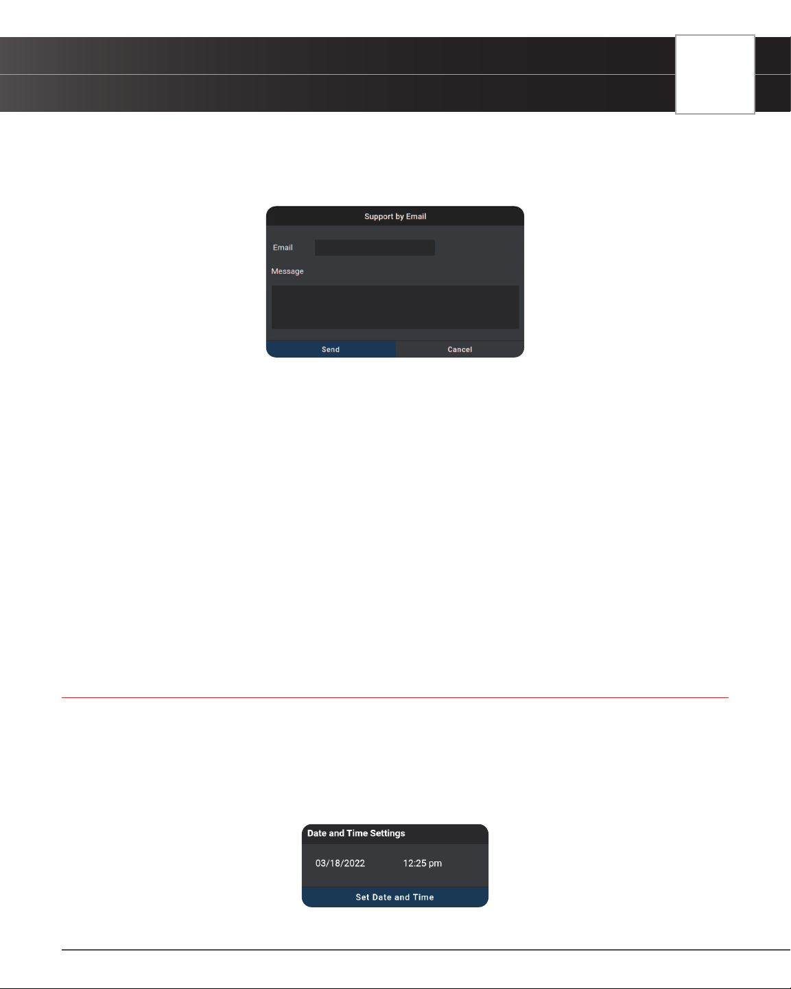
SETTINGS
Date and Time Settings
79
n The Settings screen displays.
2. Tap Email Support.
n The Support by Email dialog displays.
n The Email eld shows the most recently entered email address for the tablet. If no address was
previous entered, the Email eld shows an empty text box.
NOTE: You MUST provide a personal email address to receive a reply from Innova
Technical Support via email.
3. To enter an Email address for the rst time:
n Tap the Email text box, then enter your personal email address.
4. To change an existing Email address:
n Tap Change. The current Email address displays in an editable text box.
5. Tap the Send button to send your email to Innova Technical Support.
n To cancel your message without sending, tap Cancel to return to the Technical Support dialog.
n A conrmation message displays. Tap Close to close the message.
DATE AND TIME SETTINGS
Here you can set the current date and time for the tablet.
Setting Date and Time Formats
1. Tap the SETTINGS tab on the Home screen and scroll to the Date and Time Settings eld.
n The Date and Time Settings eld shows the currently set date and time for the tablet.
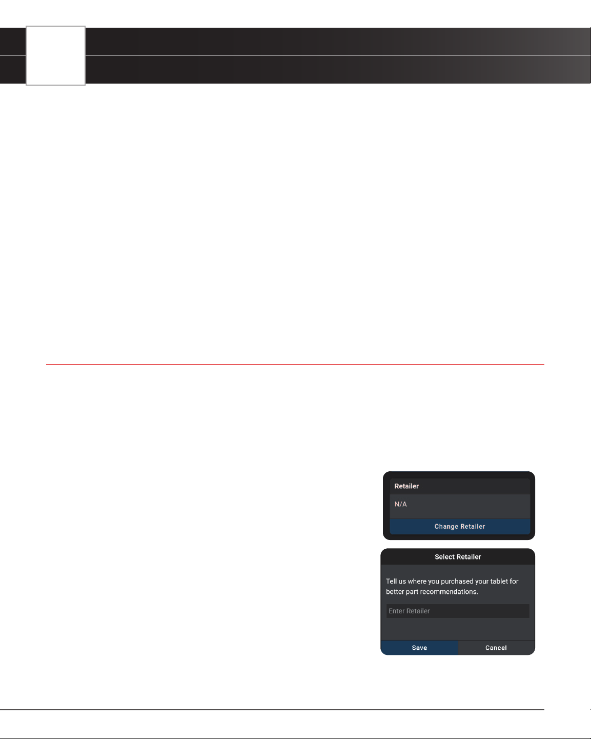
80
SETTINGS
Retailer Selection
2. To specify the current date:
n Tap the date format eld.
━ The Set Date dialog displays.
n Scroll the “month,” “day,” and “year” elds to set the current calendar date, then click DONE.
━ Click CANCEL to close the Set Date dialog and retain the previous date.
3. To specify the current time:
n Tap the time format eld.
━ The Set Time dialog displays.
n Scroll the “hour,” “minute,” and “am/pm” elds to set the current time, then tap DONE.
━ Tap CANCEL to close the Set Time dialog and retain the previous time.
4. Tap Set Date and Time to save your changes.
n A conrmation message displays. Tap Close to close the message.
RETAILER SELECTION
To get the best possible parts recommendations, provide the name of the retailer where you purchased your INNOVA
Smart Diagnostic System tablet.
Specifying the Retailer
1. Scroll the Settings page to the Retailer eld.
n If you previously specied a retailer, the name of the retailer is shown in the upper left corner
of the Retailer eld.
2. Tap Change Retailer.
n The Select Retailer dialog displays.
3. Tap the Enter Retailer text box, then enter the name of the location
from which you purchased your tablet (or another local retailer, as
desired) using the keyboard.
4. When the desired retailer has been entered, tap the Save button to
save your changes and return to the Retailer eld.
n To cancel changes and retain the current retailer, tap Cancel
to return to the Retailer eld.
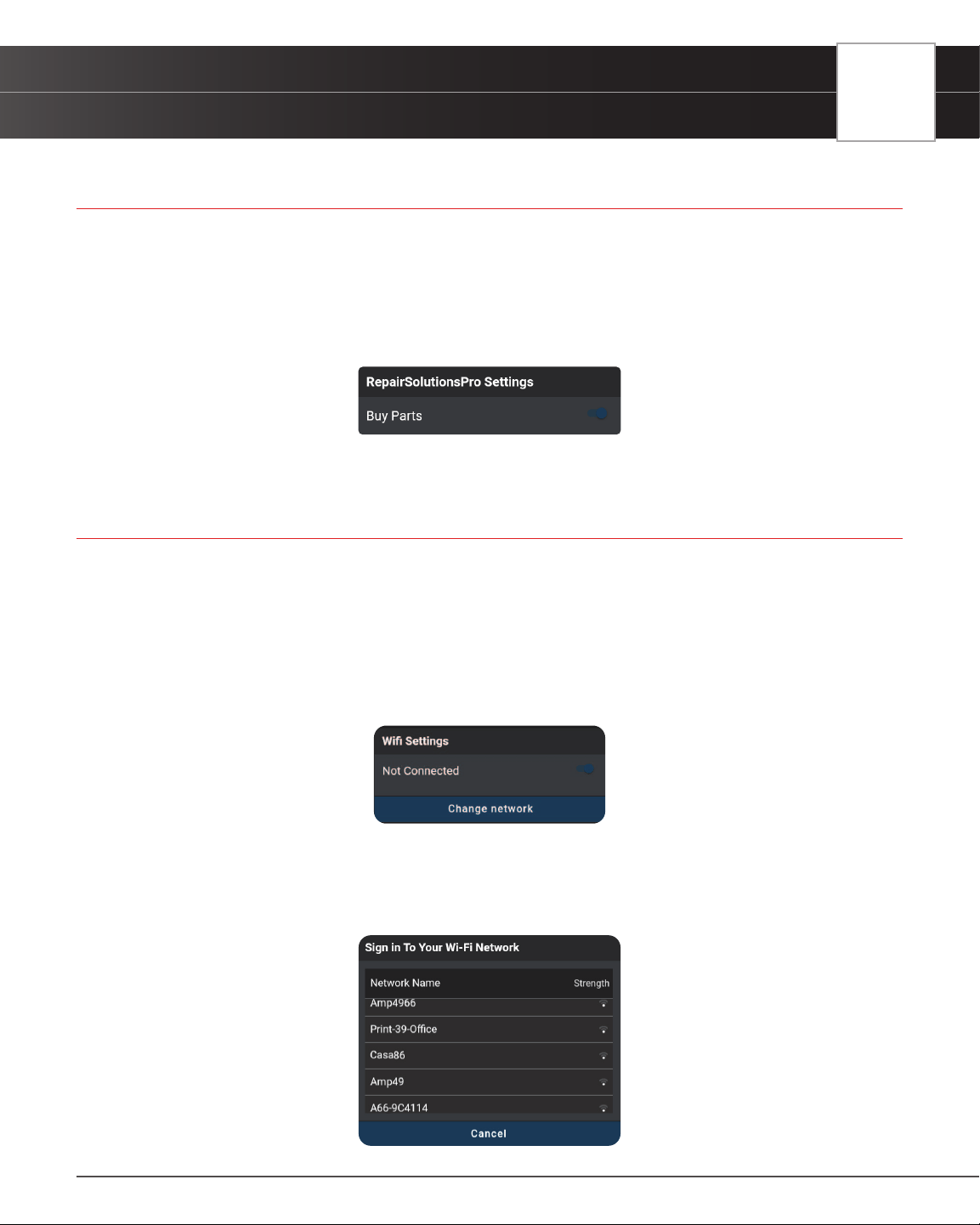
SETTINGS
RepairSolutionsPRO Settings
81
RepairSolutionsPRO SETTINGS
You have the option and convenience to purchase the associated part for each recommended x. Each part includes
a button, which links to your selected retailer and provides an estimated cost. This feature can be turned on and off
as desired.
1. Scroll the Settings page to the RepairSolutionsPRO Settings eld.
2. Tap the Toggle Switch to either turn On or Off the Buy Parts feature.
WI-FI SETTINGS
To access all the features provided in your diagnostic tablet, a local WI-FI network connection is necessary.
Connecting to a Wi-Fi Network
1. Scroll the Settings page to the Wi-Fi Settings eld.
n If you are currently connected to a Wi-Fi network, the network name is shown; if not, it shows
“Not Connected”.
2. Tap Change Network.
n The Sign In To Your Wi-Fi Network dialog displays.
n The dialog lists all available Wi-Fi networks within range of the tablet.

82
SETTINGS
Regional Settings
3. Swipe up or down to scroll to the desired Wi-Fi network, then tap your network name.
n To cancel changes and retain your current network connection, tap Cancel to return to the Wi-
Fi Settings eld.
n The Enter Password dialog displays.
4. Tap the Password text box, then enter the Wi-Fi network password using the keyboard.
n As you type, the password displays as a series of bullets by default. Tap show to show the
password as you type. Tap hide to display the password as bullets.
5. When the password has been entered, tap the Connect button to save your changes and connect to the selected
Wi-Fi network.
n Tap Cancel to cancel your changes and return to the Sign In To Your Wi-Fi Network dialog to
select a different network.
REGIONAL SETTINGS
Allows you to set the unit of measurement for the tablet’s display to US (Imperial) or Metric.
Conguring Regional Settings
1. Scroll the Settings page to the Regional Settings eld.
2. Tap the currently selected unit of measurement to display the menu. Select the radio button for the desired unit
of measurement, then tap OK.
n Tap CANCEL to close the menu and retain the previously selected unit of measurement.
LANGUAGE
Lets you set the display language for the tablet to English or Spanish.
Setting the Display Language
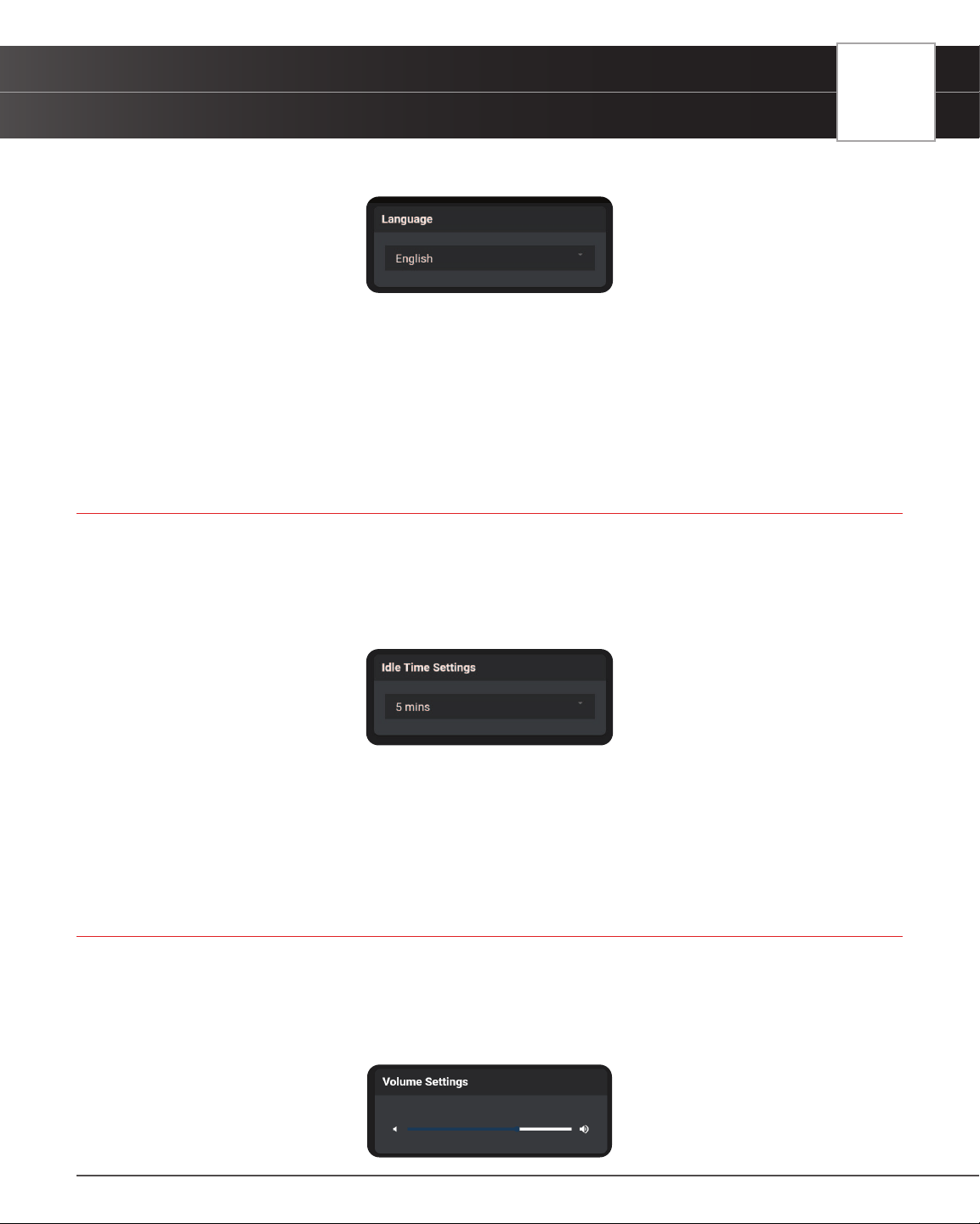
SETTINGS
Idle Time Settings
83
1. Scroll the Settings page to the Language eld.
2. Tap the currently active language to display the Select Language menu. Select the radio button for the desired
language, then tap OK.
n Click CANCEL to close the Select Language menu and retain the previously selected display
language.
n The display refreshes to show text in the selected language.
IDLE TIME SETTINGS
Lets you set the length of “idle” time before the tablet enters “standby” mode.
Idle Time Settings
1. Scroll the Settings page to the Idle Time Settings eld.
2. Tap the currently active idle time value to display the Select Idle Time menu. Select the radio button for the
desired idle time value, then tap OK.
n Tap CANCEL to close the Select Idle Time menu and retain the previously selected idle time
value.
VOLUME SETTINGS
Sets the volume level of the tablet speaker.
Adjusting Speaker Volume
1. Scroll the Settings page to the Volume Settings eld.
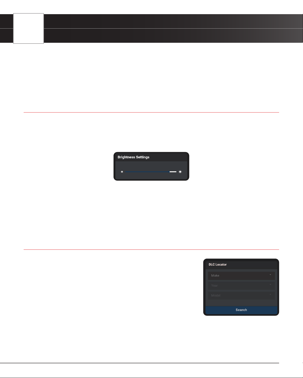
84
SETTINGS
Brightness Settings
2. Use the Volume “slider” to increase or decrease speaker volume:
n Touch and slide right to make the volume louder.
n Touch and slide left to make the volume softer.
━ The current Volume setting shows above the slider as you adjust the slider position.
BRIGHTNESS SETTINGS
Lets you adjust the brightness of the display screen.
Adjusting Display Brightness
1. Scroll the Settings page to the Brightness Settings eld.
2. Use the Brightness “slider” to increase or decrease display brightness:
n Touch and slide right to make the display brighter.
n Touch and slide left to make the display darker.
━ The current Brightness setting shows above the slider as you adjust the slider position
DLC LOCATOR
Use this search function to quickly nd the location of the Data Link Connector
(DLC) for a specied vehicle.
Using the DLC Locator
1. Scroll the Settings page to the DLC Locator eld.
2. Tap Make to display the Select Make menu. Select the radio button for the
desired vehicle manufacturer, then tap OK
3. Tap Year to display the Select Year menu. Select the radio button for the
vehicle model year, then tap OK.
4. Tap Model to display the Select Model menu. Select the radio button for the desired vehicle model, then tap OK.
5. Tap the Search button.
n The DLC Locator screen for the selected vehicle displays.
n The DLC Location screen shows a description of the DLC location and whether the DLC is
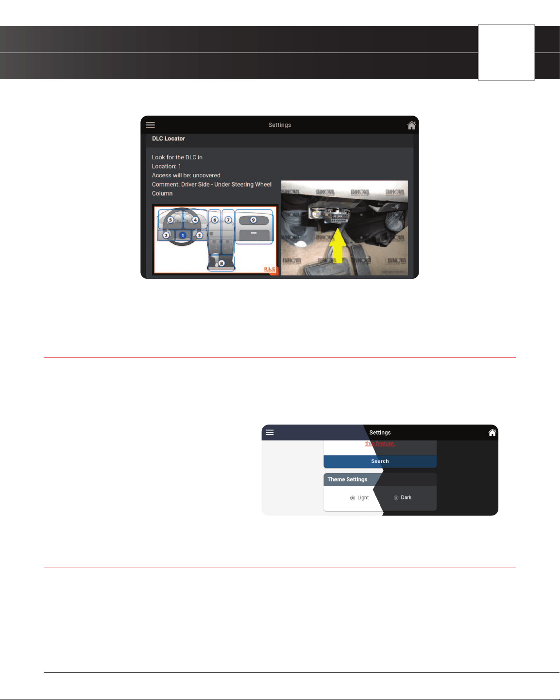
SETTINGS
Theme Settings
85
“covered” or “uncovered,” and includes a picture of the DLC location.
6. Tap the Close button to close the DLC Locator screen and return to the Settings page.
THEME SETTINGS
Allows you to change the appearance of the tablet screens.
Changing Theme Settings
1. Scroll the Settings page to the Theme
Settings eld
n Tap the Light selection to make the
tablet’s screen contrast to white /
brighter mode.
n Tap the Dark selection to make the
tablet’s screen contrast to dark gray
/ darker mode.
ACCOUNT INFORMATION
Create, access, and edit your RepairSolutionsPRO™ account.
CREATE AN ACCOUNT
1. Tap on Settings on the home screen and scroll down to the “Account Information” section.
2. Tap the Create an Account button to begin.
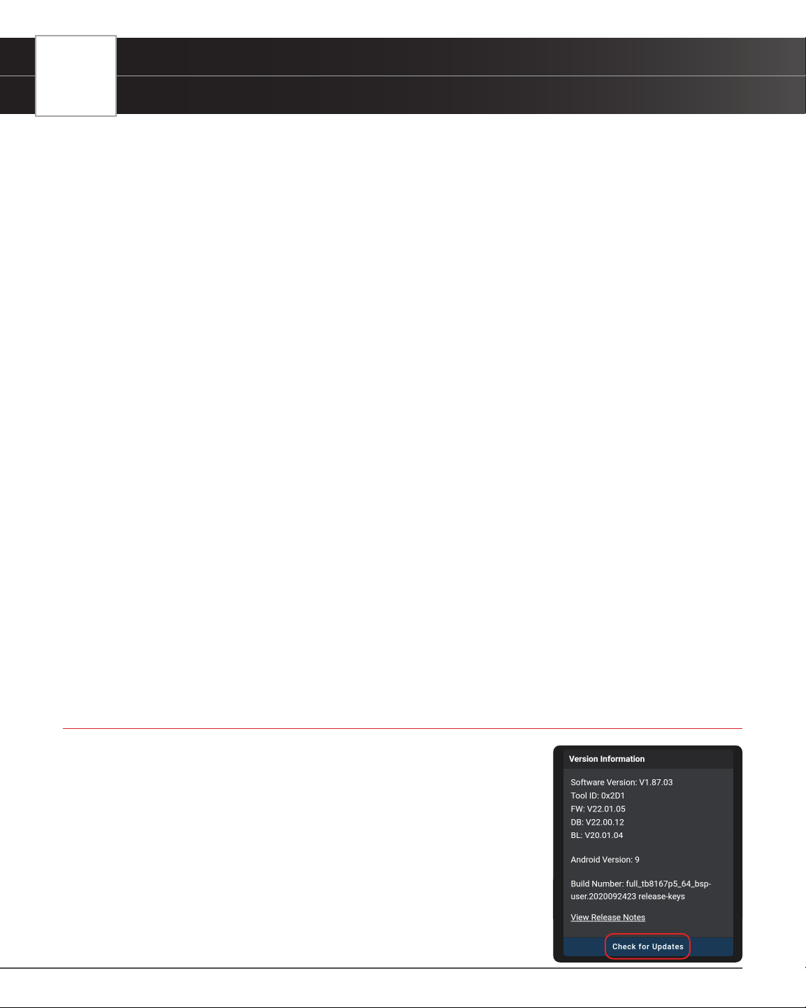
86
SETTINGS
Version Information
3. Complete the displayed form with your name, email address, your desired password, and other personal
information.
4. Complete your registration by reviewing the terms and tap on the Create Account button at the bottom of the
form.
n A conrmation message displays with “The account has been created successfully”. If properly
signed in, the Account Information screen displays your account name and email.
EDIT ACCOUNT INFORMATION
Allows you to change your password and other personal information.
1. Tap on Settings on the home screen and scroll down to the “Account Information” section.
2. Make any necessary changes as desired and tap on the Save Changes button to conrm your edits.
ACCOUNT LOG IN
1. Tap on Settings on the home screen and scroll down to the “Account Information” section.
2. Tap the Log In button.
n The RSPRO “Log In” dialog displays
3. Enter your credentials and tap the Login button.
RESET ACCOUNT PASSWORD
1. Tap on Settings on the home screen and scroll down to the “Account Information” section.
2. Tap the Log In button.
n The RSPRO “Log In” dialog displays
3. Tap on Forgot password and follow the prompts.
VERSION INFORMATION
The Version Information eld shows the tablet’s Software Version, Tool Version,
and other related specications. This screen also lets you check for software
updates or report an issue with the tablet.
Viewing “Version Information”
1. Scroll the Settings page to the Version Information eld.
n The eld shows the tablet’s current Software Version, Tool ID,
rmware version (FW), database version (DB), bootloader
version (BL), Android Version and Build Number for the tablet.
n Tap View Release Notes to see what was updated with the current
version.
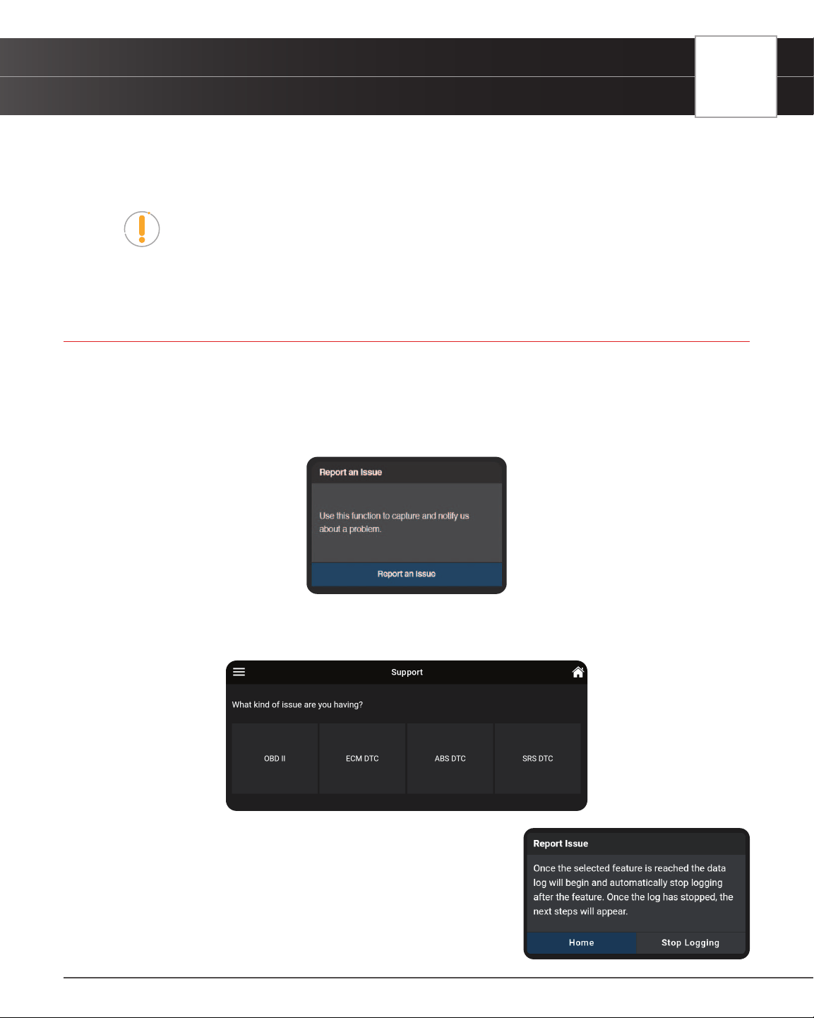
SETTINGS
Report an Issue
87
2. Tap Check for Updates to check and download any updates.
n Tablet veries an Internet connection and checks for any updates. If an update is available, user
is given the option to view the release notes, update the tool, or enable an update reminder.
NOTE: If the tablet is connected to the Internet and an update is available, the
tool will automatically display an update notication dialog on the Home screen. If
presented, simply tap the More Info button to proceed, or tap the Remind Me Later
button to update at a later time.
REPORT AN ISSUE
Did you encounter an OBD II connection issue or a DTC specic problem? Use this feature to record a log of the issue
and send a direct message to Innova’s Technical Team to get support.
To report an issue:
1. Scroll to the Report an Issue eld.
2. Tap the Report an Issue button.
n A selection page displays.
3. Tap the type of issue you wish to report; OBD II, ECM DTC, ABS DTC
or SRS DTC.
n An instructional dialog displays:
4. Tap the Home button to begin.
n The display returns to the Home Page, and the red Data Log
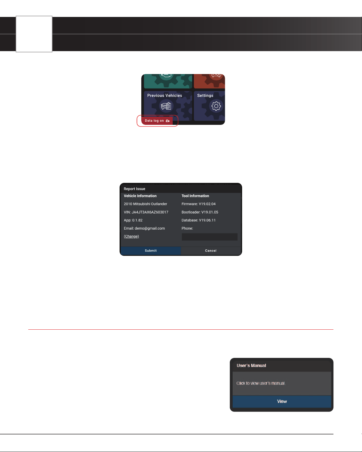
88
SETTINGS
View User’s Manual
On icon shows in the lower left corner of the screen.
5. Proceed to perform the steps to demonstrate where you encountered the issue.
6. Tap the Data Log On icon to return to the instructional dialog
7. Tap the Stop Logging button
n A dialog screen displays with the vehicle’s information and tool information
8. Enter your Email, Phone, and Issue Description (these are required elds).
n If an email is displayed, tap (Change) to enter a new email address
9. Tap Submit to send your report, or Cancel to exit and return to the Home screen.
VIEW USER’S MANUAL
Get access to the most current version of the tablet User’s Manual.
Viewing the User’s Manual:
1. Scroll to the User’s Manual eld.
2. Tap View to download and read a PDF version of the tablet’s most
current User’s Manual.
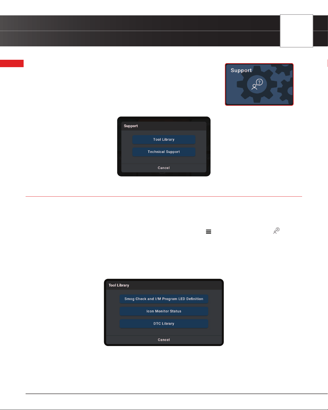
SUPPORT
Tool Library
89
SUPPORT
The SUPPORT tab includes various support resources, including:
n Tool Library – access tool denitions and terminology
n Technical Support – directly connect with Innova’s Technical
Support team via the tablet’s email function
TOOL LIBRARY
Accesses denitions of tool icons and Diagnostic Trouble Codes (DTCs).
Using the Tool Library:
1. From the Home page tap SUPPORT. (You can also access it from the
Main Menu by tapping on Support)
n The Support selection dialog displays.
2. Tap the Tool Library button.
n The Tool Library dialog appears.
3. Select from the provided options.
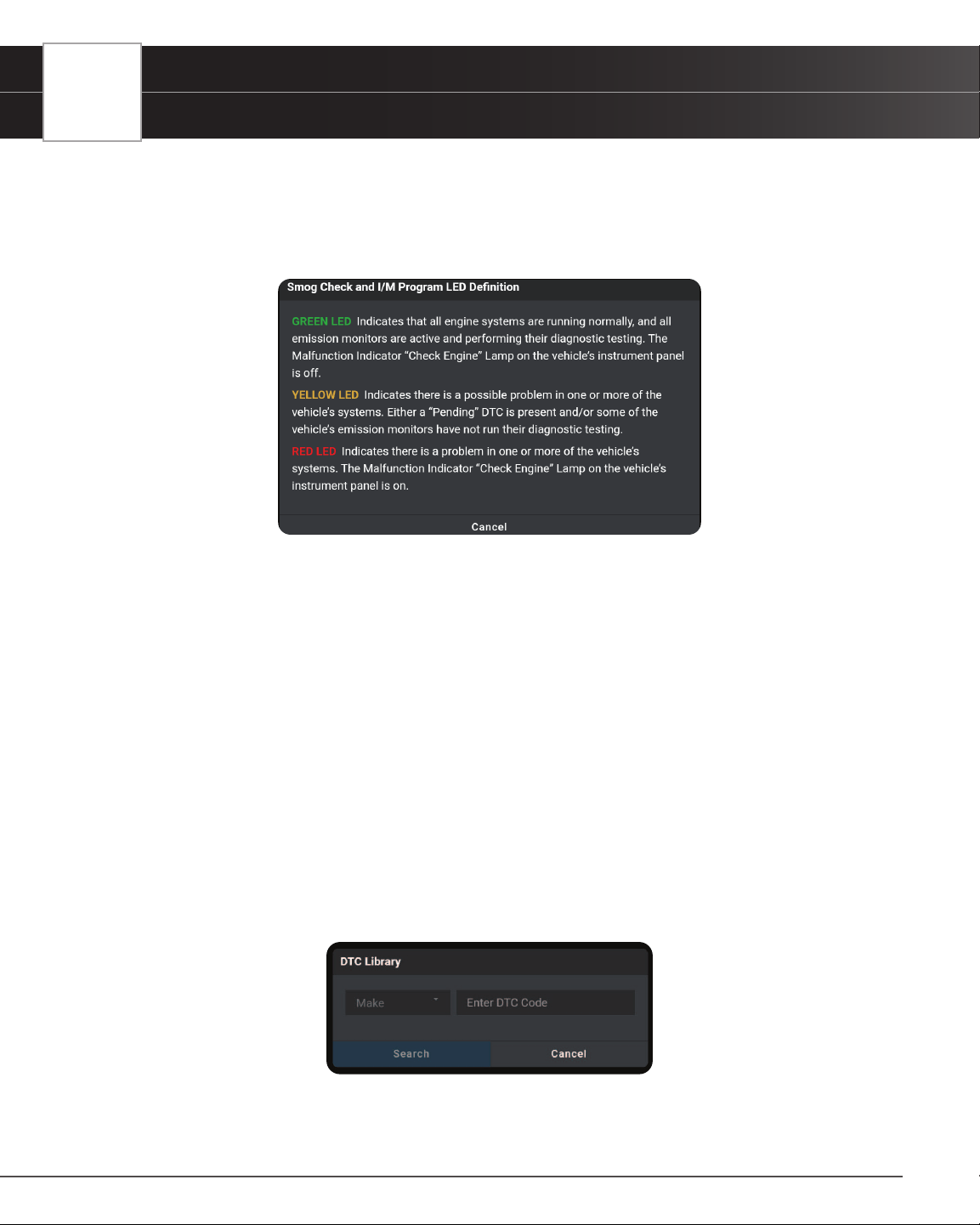
90
SUPPORT
Tool Library
n Tap Cancel to return to the Support dialog screen.
SMOG CHECK AND I/M PROGRAM LED DEFINITION
1. Tap the Smog Check and I/M Program LED Denition button
n The Smog Check and I/M Program LED Denition dialog displays
2. Tap Cancel to return to the Tool Library selection screen
ICON MONITOR STATUS
Denes the icon monitor status’ color coding and provides tips on how to proceed.
1. Tap the Icon Monitor Status button
n The Icon Monitor Status dialog displays
2. Tap Cancel to return to the Tool Library selection screen
DTC LIBRARY
Searches for the Diagnostic Trouble Code (DTC) denitions for most 1996 and newer vehicles.
1. Tap the DTC Library button.
n The DTC Library dialog displays.

SUPPORT
Technical Support
91
2. Tap on Make and scroll to select the vehicle’s make from the pull-down menu.
3. Tap on Enter DTC Code box, enter the numeric DTC you want to dene using the keyboard.
n Be sure to include all characters – letters and numbers.
4. Tap Search to begin the search.
n Search dialog appears with the retrieved denition.
5. Tap Cancel to return to the Tool Library selection screen
TECHNICAL SUPPORT
The Innova Electronics technical team is based in Irvine, California and is always ready to help!
To connect with Technical Support:
1. From the Home page, tap SUPPORT. (You can also access it from the Main Menu by tapping on Support)
n The Support selection dialog displays.
2. Tap the Technical Support button.
n The Technical Support dialog appears.
3. Tap Email Support.
n The Support by Email dialog displays.
n The Email eld shows the most recently entered email
address for the tablet. If no address was previous
entered, the Email eld shows an empty text box.
NOTE: You MUST provide a personal email address
to receive a reply from Innova Technical Support via
email.
4. To enter an Email address for the rst time:
n Tap the Email text box, then enter your personal email address.
5. To change an existing Email address:
n Tap Change. The current Email address displays in an editable text box.
6. Tap the Send button to send your email to Innova Technical Support.
n To cancel your message without sending, tap Cancel to return to the Technical Support dialog.
n A conrmation message displays. Tap Close to close the message.

92
WARRANTY+ CUSTOMER SERVICE
Limited Warranty
WARRANTY+ CUSTOMER SERVICE
LIMITED WARRANTY
The Manufacturer warrants to the original purchaser that this unit is free of defects in materials and workmanship under
normal use and maintenance for a period of one (1) year from the date of original purchase.
If the unit fails within the one (1) year period, it will be repaired or replaced, at the Manufacturer’s option, at no charge,
when returned prepaid to the Service Center with Proof of Purchase. The sales receipt may be used for this purpose.
Installation labor is not covered under this warranty. All replacement parts, whether new or remanufactured, assume
as their warranty period only the remaining time of this warranty.
This warranty does not apply to damage caused by improper use, accident, abuse, improper voltage, service, re,
ood, lightning, or other acts of God, or if the product was altered or repaired by anyone other than the Manufacturer’s
Service Center.
The Manufacturer, under no circumstances shall be liable for any consequential damages for breach of any written
warranty of this unit. This warranty gives you specic legal rights, and you may also have rights, which vary from state
to state. This manual is copyrighted with all rights reserved. No portion of this document may be copied or reproduced
by any means without the express written permission of the Manufacturer. THIS WARRANTY IS NOT TRANSFERABLE.
For service, send via U.P.S. (if possible) prepaid to Manufacturer. Allow 3-4 weeks for service/repair.
CUSTOMER SERVICE
Our ASE Certied technical staff is here to help if you have any questions or require service. For information on
UPDATES and OPTIONAL ACCESSORIES, please contact your local store, distributor or Innova’s Service Center.
USA & Canada: (800) 544-4124
Monday through Friday: 6:00 AM to 6:00 PM PST
All others: (714) 241-6802
Monday through Friday: 6:00 AM to 6:00 PM PST
FAX: (714) 241-3979 (24 Hr.)
Web: www.innova.com

GLOSSARY
OBD2 Terminology
93
GLOSSARY
OBD2 TERMINOLOGY
The following terms and their denitions are related to OBD2 systems.
n Powertrain Control Module (PCM) - The PCM is the OBD2 accepted term for the vehicle’s “on-board
computer.” In addition to controlling the engine management and emissions systems, the PCM also
participates in controlling the powertrain (transmission) operation. Most PCMs also have the ability to
communicate with other computers on the vehicle (ABS, ride control, body, etc.).
n Monitor - Monitors are “diagnostic routines” programmed into the PCM. The PCM utilizes these programs
to run diagnostic tests, and to monitor operation of the vehicle’s emissions-related components or
systems to ensure they are operating correctly and within the vehicle’s manufacturer specications.
Currently, up to fteen Monitors are used in OBD2 systems. Additional Monitors will be added as the
OBD2 system is further developed.
NOTE: Not all vehicles support all fteen Monitors
n Enabling Criteria - Each Monitor is designed to test and monitor the operation of a specic part of the
vehicle’s emissions system (EGR system, oxygen sensor, catalytic converter, etc.). A specic set of
“conditions” or “driving procedures” must be met before the computer can command a Monitor to run
tests on its related system. These “conditions” are known as “Enabling Criteria.” The requirements and
procedures vary for each Monitor. Some Monitors only require the ignition key to be turned “On” for them
to run and complete their diagnostic testing. Others may require a set of complex procedures, such
as, starting the vehicle when cold, bringing it to operating temperature, and driving the vehicle under
specic conditions before the Monitor can run and complete its diagnostic testing.
n Monitor Has/Has Not Run - The terms “Monitor has run” or “Monitor has not run” are used throughout
this manual. “Monitor has run,” means the PCM has commanded a particular Monitor to perform the
required diagnostic testing on a system to ensure the system is operating correctly (within factory
specications). The term “Monitor has not run” means the PCM has not yet commanded a particular
Monitor to perform diagnostic testing on its associated part of the emissions system.
n Trip - A Trip for a particular Monitor requires that the vehicle is being driven in such a way that all the
required “Enabling Criteria” for the Monitor to run and complete its diagnostic testing are met. The
“Trip Drive Cycle” for a particular Monitor begins when the ignition key is turned “On.” It is successfully
completed when all the “Enabling Criteria” for the Monitor to run and complete its diagnostic testing
are met by the time the ignition key is turned “Off.” Since each of the fteen monitors is designed to
run diagnostics and testing on a different part of the engine or emissions system, the “Trip Drive Cycle”
needed for each individual Monitor to run and complete varies.
n OBD2 Drive Cycle - An OBD2 Drive Cycle is an extended set of driving procedures that takes into
consideration the various types of driving conditions encountered in real life. These conditions may
include starting the vehicle when it is cold, driving the vehicle at a steady speed (cruising), accelerating,
etc. An OBD2 Drive Cycle begins when the ignition key is turned “On” (when cold) and ends when the
vehicle has been driven in such a way as to have all the “Enabling Criteria” met for all its applicable
Monitors. Only those trips that provide the Enabling Criteria for all Monitors applicable to the vehicle to

94
GLOSSARY
OBD2 Monitors
run and complete their individual diagnostic tests qualify as an OBD2 Drive Cycle. OBD2 Drive Cycle
requirements vary from one model of vehicle to another. Vehicle manufacturers set these procedures.
Consult your vehicle’s service manual for OBD2 Drive Cycle procedures.
NOTE: Do not confuse a “Trip” Drive Cycle with an OBD2 Drive Cycle. A “Trip” Drive
Cycle provides the “Enabling Criteria” for one specic Monitor to run and complete
its diagnostic testing. An OBD2 Drive Cycle must meet the “Enabling Criteria” for all
Monitors on a particular vehicle to run and complete their diagnostic testing.
n Warm-up Cycle - Vehicle operation after an engine off period where engine temperature rises at least
40°F (22°C) from its temperature before starting, and reaches at least 160°F (70°C). The PCM uses
warm-up cycles as a counter to automatically erase a specic code and related data from its memory.
When no faults related to the original problem are detected within a specied number of warm-up cycles,
the code is erased automatically.
OBD2 MONITORS
To ensure the correct operation of the various emissions-related components and systems, a diagnostic program was
developed and installed in the vehicle’s on-board computer. The program has several procedures and diagnostic
strategies. Each procedure or diagnostic strategy is made to monitor the operation of, and run diagnostic tests on, a
specic emissions-related component or system. These tests ensure the system is running correctly and is within the
manufacturer’s specications. On OBD2 systems, these procedures and diagnostic strategies are called “Monitors.”
Currently, fteen Monitors are supported by OBD2 systems. Additional monitors may be added because of Government
regulations as the OBD2 system grows and matures. Not all vehicles support all fteen Monitors. Additionally, some
Monitors are supported by “spark ignition” vehicles only, while others are supported by “compression ignition” vehicles
only.
Monitor operation is either “Continuous” or “Non-Continuous,” depending on the specic monitor.
CONTINUOUS MONITORS
Three of these Monitors are designed to constantly monitor their associated components and/or systems for proper
operation. Continuous Monitors run constantly when the engine is running.
= Comprehensive Component Monitor (CCM)
= Misre Monitor
= Fuel System Monitor
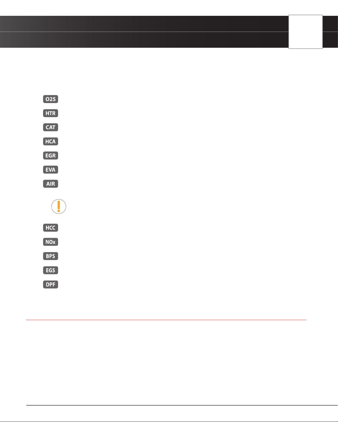
GLOSSARY
Additional Terminology + Acronyms
95
NON-CONTINUOUS MONITORS
The other twelve Monitors are “non-continuous” Monitors. “Non-continuous” Monitors perform and complete their
testing once per trip.
= Oxygen Sensor Monitor
= Oxygen Sensor Heater Monitor
= Catalyst Monitor
= Heated Catalyst Monitor
= EGR (Exhaust Gas Recirculation) System Monitor
= EVAP System Monitor
= Secondary Air System Monitor
NOTE: The following Monitors became standard beginning in 2010. The majority of
vehicles produced before this time will not support these Monitors.
= NMHC (Non-Methane Hydrocarbon Converting) Catalyst Monitor
= NOx Adsorber Monitor
= Boost Pressure System Monitor
= Exhaust Gas Sensor Monitor
= PM (Particulate Matter) Filter Monitor
ADDITIONAL TERMINOLOGY + ACRONYMS
n ABS = Anti-Lock Brakes
n DLC = Data Link Connector (vehicle’s data port)
n DTC = Diagnostic Trouble Codes
n KOEO = Key On, Engine Off
n KOER = Key On, Engine Running
n MIL = Malfunction Indicator Lamp (Check Engine Light)

96
GLOSSARY
Additional Terminology + Acronyms
n OBD = On Board Diagnostics
n OBD2 / OBD II = On Board Diagnostics, Second Generation
n OEM = Original Equipment Manufacturer
n PID = Parameter Identication Data
n SRS = Safety Restraint System
n TPMS = Tire Pressure Monitoring System
n TSBs = Technical Service Bulletins

Copyright © 2023 IEC. All Rights Reserved.
v.1.87
Innova Electronics Corp.
17352 Von Karman Ave.
Irvine, CA 92614