Loading ...
Loading ...
Loading ...
4
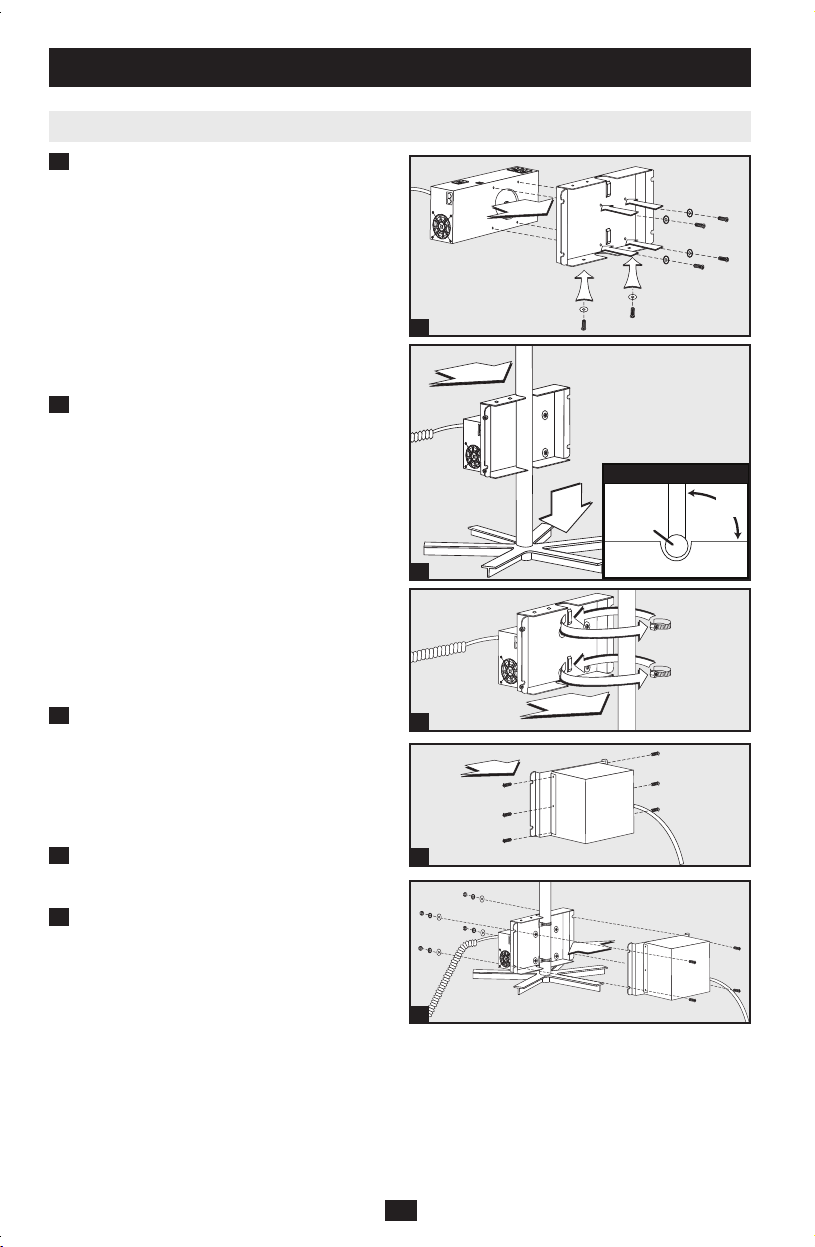
Mounting (Power Supply & Battery Module) continued
Required Hardware: #10-32 x 3/8 Phillips Head
Screws (4); #10-32 Star Washers (4). Attach the
Power Supply Module to the mounting bracket as
shown. Make sure that the Power Supply Module
is oriented as shown in the diagram with its outlets
facing up.
Required Hardware: #10-32 x 1 Phillips Head
Screws (2); #10-32 Fender Washers (2). Attach
hardware to the bottom of the mounting bracket.
Fully tighten the screws. (NOTE: These screws are
designed to protrude downward even when fully
tightened, so as to engage the cart's legs in step 1B.)
Using one or more assistants, lift the Power
Supply Module/mounting bracket and place
it around the cart's center pole as shown.
(NOTE: Since the mounting bracket is
designed to accommodate a wide variety of
center pole sizes, attach the screw clamps as
described in step 1C.) When lowering the
mounting bracket into place, make sure that
the screws on the bottom of the bracket
engage the cart's legs in order to prevent the
retrofit kit from rotating around the cart's
center pole. To minimize rotation, make sure
the side of the mounting bracket is
perpendicular (90°) in relation to one of the
cart's legs, as shown in the “Top View”
diagram. Lift and readjust if needed.
The mounting bracket is designed to
accommodate a wide variety of center pole
sizes. To secure bracket to center pole, wrap
the two included screw clamps around the
cart's center pole and through the raised slots
on the mounting bracket. Use a screwdriver
to fully tighten clamps.
Required Hardware: #8-32 x 3/8 Phillips Head
Screws w/Washers (6). Attach the Battery Module
to the mounting bracket as shown.
Required Hardware: 5/16-8 x 5/8 Hex Screws (4);
5/16 Flat Washers (4); 5/16 Lock Washers (4);
5/16 Nuts (4). Using one or more assistants, lift the
Battery Module (with its mounting bracket) and
attach it to the Power Supply Module (with its
mounting bracket) as shown.
1A
Option 1: Mounting on a Center Pole
1B
1C
1D
1E
1A
LEG
MOUNTING BRACKET
CENTER
POLE
90°
Top View
1B
1C
1E
1D
200910241 93-2704-EN.indd 4 5/17/2010 5:16:48 PM
Loading ...
Loading ...
Loading ...