Loading ...
Loading ...
Loading ...
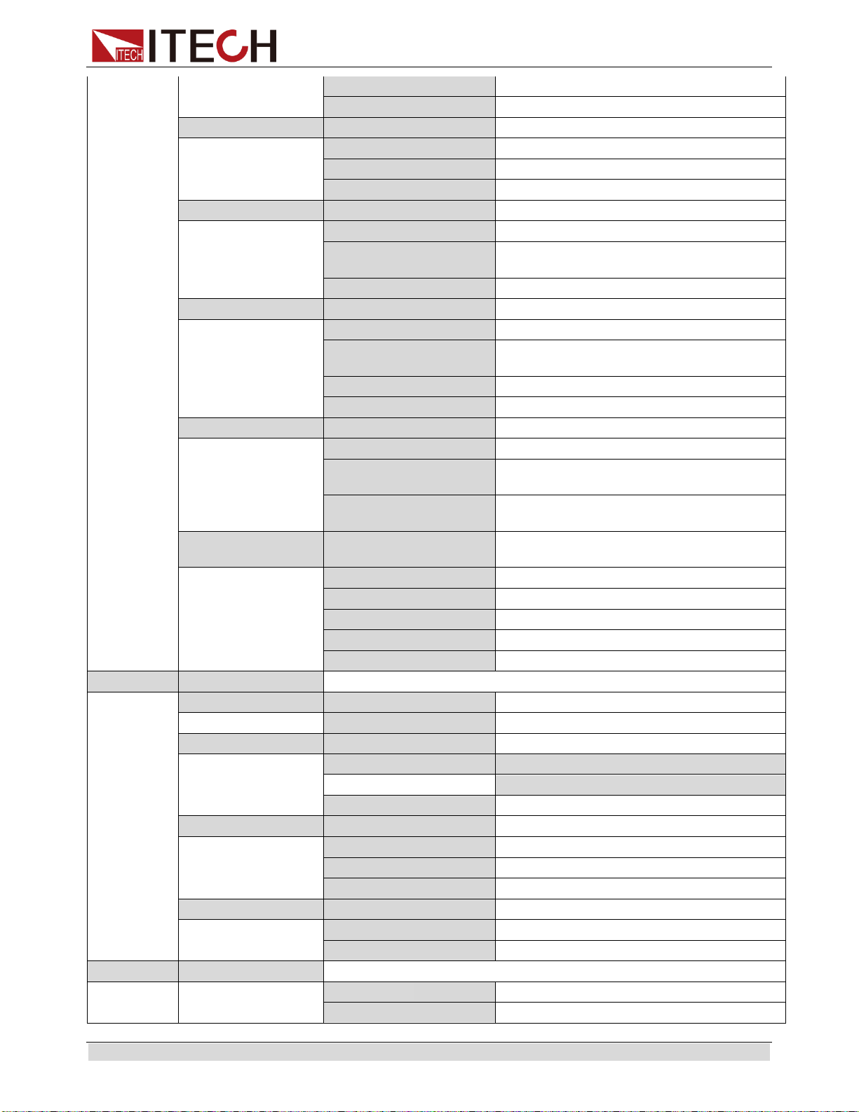
Basic operation
Copyright © ITECH Electronic Co., Ltd. 20
On
Lock the rotary knob
Off(default)
Unlock the rotary knob
Comm
COMMUNICATION
Communication port select
RS232(def)
RS232
USBTMC
USB
GPIB
GPIB
Port
PORT FUNCTION
Select mode of digital port
Trigger
Trigger mode
RI/DFI
Power switch control and discrete fault
indication
Digital
Data port
Trig
TRIGGER SOURCE
Trigger source select
Manual
Trigger by keys on the front panel
External
Ext. Trigger signal is applied to the
digital port in the rear panel.
Bus
Remote command trigger mode.
Immediat
Trigger by TRIG:IMM command
RI
RI MODE
Config RI (Remote Inhibit) mode
Off
Disable this function
Latching
At the falling edge of the TTL level, the
output turns on.
Live
The output is on at high level and turned
off at low level.
DFI
DFI SOURCE
Config DFI (Discrete Fault Indicator)
mode
Off
Disable this function
QUES
Question bit
OPER
Operation bit
ESB
Event State bit
RQS
Require bit
System
SYSTEM MENU
System menu
Limit_volt
LIMIT VOLTAGE SET
Limit voltage setting
Limit=30.10V
On_Timer
ON TIMER STATE
Output timer function state
On
ON TIMER SET
timer = 60.000(0.01 - 60000.0S)
Off(default)
Turn off the output timer.
DVM
DVM RANGE
Digital multimeter range setting
Auto
Auto range
Low
Low range
High
High range
OutMode
OUTPUT MODE…
Set Output Mode
Volt-Wave Prio
Voltage output priority
Curr-Wave Prio
Current output priority
Range
RANGE MENU
Set Output Range
Low_Range
Low range
High_Range
High range
Loading ...
Loading ...
Loading ...