Loading ...
Loading ...
Loading ...
(1) DIP switch must be set with power sources of the indoor
and outdoor units in OFF state. Otherwise, the settings are
invalid.
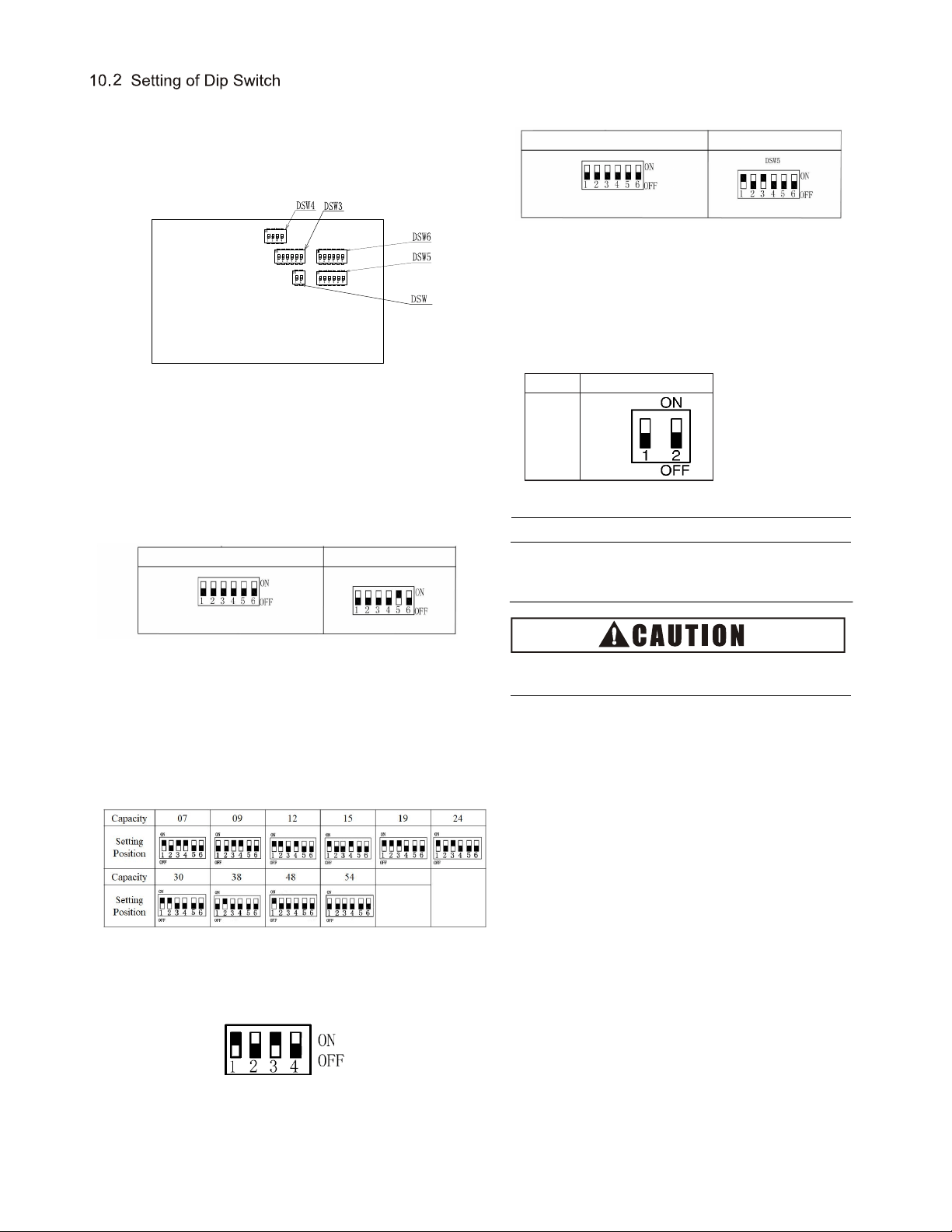
(2) The location of DIP switch is shown in the figure below.
(b)
Capacity Code Setting (DSW3)
No setup is required.
The code is set before delivery. This switch is used to
set the capacity of indoor unit.
(a)
(3) The PCB of indoor unit is furnished with 5 DIP switches
that must be set based on the following requirements
before test run. The system must not be started before
the completion of DIP setup.
All indoor units must be numbered (DSW6) as shown
in the figure below. The outdoor unit numbering must
start with "0".
(c) Model Code Setting (DSW4)
No setup is required. The code is set before delivery.
Default No.1 and 3 ON.
Note:
Symbol "■" indicates the location of DIP switch.
The position indicated in the diagram is in the factory-set
state.
The power supply shall be turned off before the setup of
DIP switch. Otherwise, the settings will be invalid.
(d) Cooling System Code No. Setting (DSW5)
The setup is needed. All are set to OFF before delivery.
Refrigerant System Setting
Ex.) Set system No. 5
DSW5 are set to "0" before delivery. 64 indoor units can be
connected.
(e) Other function setting (DSW9)
No setup is required. The code is set before delivery.
DSW6(Setting 0~63)
Ex.)Set machine No.16
No.5 ON
DSW6 are set to "0" before delivery. 64 indoor units
can be connected.
DSW5(Setting 0~63)
16
9
Model
models
Setting
Position
mar or DS - nary 8421 co
comparon a on n pa
mar or DS5 - nary 8421 co
comparon a on n pa
Loading ...
Loading ...