Loading ...
Loading ...
Loading ...
4
4. RELIEF VALVE — A new combination pressure and temperature relief
valve, complying with the Standard for Relief Valves and Automatic Gas
Shutoff Devices for Hot Water Supply Systems, ANSI Z21.22, must be
installed in the opening provided and marked for the purpose on the
water heater. (Refer to Fig. 2 or 3.) No valve of any type should be
installed between the relief valve and the tank. Local codes shall govern
the installation of relief valves.
The pressure rating of the relief valve must not exceed 150 psi, the
maximum working pressure of the water heater as marked on the rating
plate. The BTUH Rating of the relief valve must not be less than the
input rating of the water heater as indicated on the rating label located on
the front of the heater (1 watt = 3.412 BTUH).
Connect the outlet of the relief valve to a suitable open drain so that the
discharge water cannot contact live electrical parts and to eliminate
potential water damage. Piping used should be of a type approved for hot
water distribution. The discharge line must be no smaller than the outlet of
the valve and must pitch downward from the valve to allow complete
drainage (by gravity) of the relief valve and discharge line. The end of the
discharge line should not be threaded or concealed and should be
protected from freezing. No valve of any type, restriction or reducer
coupling should be installed in the discharge line.
5. TO FILL WATER HEATER — Make certain drain valve is completely
closed. Open shut-off valve in cold water supply line. Open each hot water
faucet slowly to allow air to vent from the water heater and piping. A steady
flow of water from the hot water faucet(s) indicates a full water heater.
Tank MUST BE full of water before power is turned on. Heating
element(s) WlLL BE DAMAGED if energized for even a short time while
tank is dry. The water heater’s warranty does not cover damage or
failure resulting from operation with an empty or partially empty tank.
(Reference is made to the limited warranty for complete terms and
conditions.)
6. ELECTRICAL CONNECTIONS — The voltage requirements and wattage
load for all heaters is specified on the rating plate. Table 1 recommends
minimum branch circuit sizing based on the National Electrical Code. All
wiring must conform to local codes or latest edition of National Electrical
Code ANSI/NFPA 70.
Some models are supplied with a plug connected power supply cord for use
only in 120 VAC applications. The cord must be connected to a properly
Installation
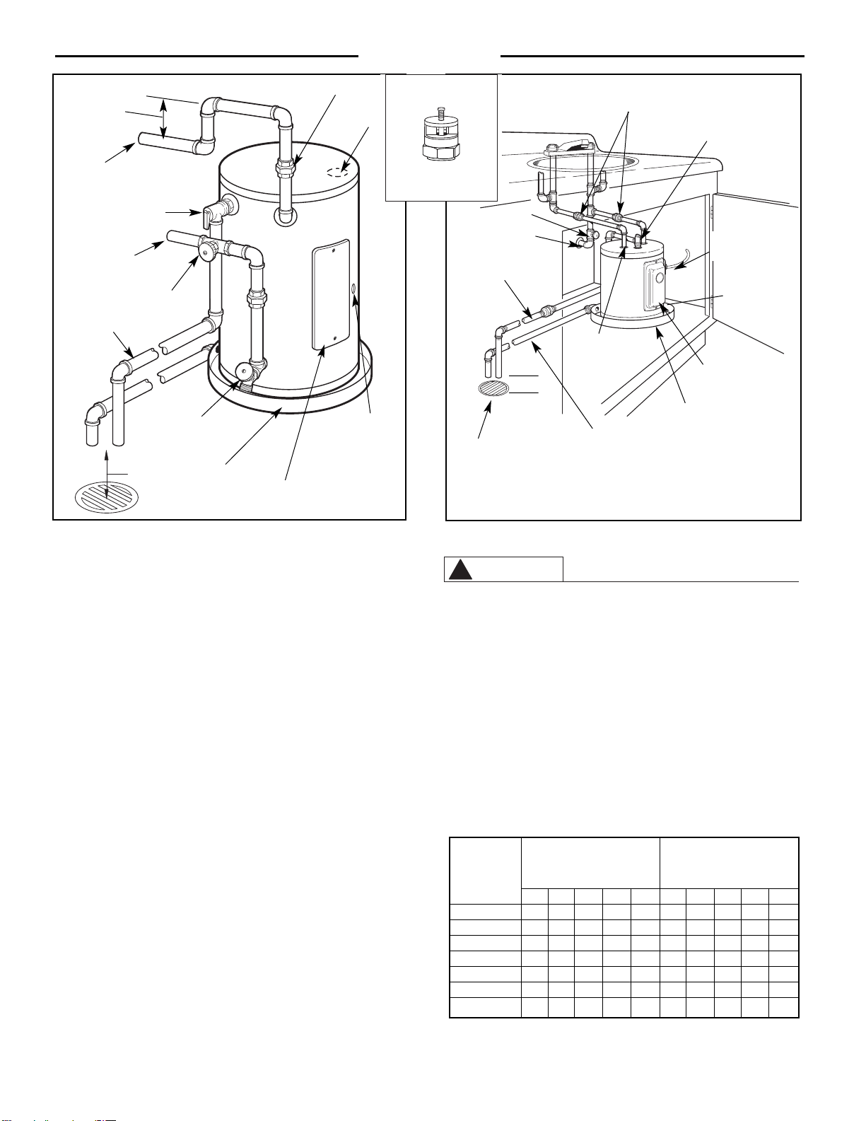
Figure 2. — Typical Side Connect Installation
Figure 3. — Typical Under Counter Top Connect Installation
WARNING
!
Recommended
Heat Trap
6" Min.
Hot Water
Outlet to Fixtures
Opening for
1/2" or 3/4"
Electrical Fitting
(Use only Copper
Conductors)
Jacket Access
Panel
Union
Shut-Off
Valve
Air Gap
6"
Auxiliary
Catch Pan
Drain Valve
(Not Supplied)
Temperature & Pressure
Relief Valve
To Cold Water
Supply
Relief Valve
Discharge
Line to suitable
open drain
Table 1. — Branch Circuit Sizing and Wire Size
Guide Based on N.E.C. ANSI / NFPA 70
Shut-Off Valve
Unions
Cold Water Supply
Relief Valve
Discharge Line
Hot Water Outlet
(To Fixtures)
Suitable Open Drain
6"
Auxiliary Catch Pan
Auxiliary Catch Pan Drain Line
Jacket Access Panel
Power Supply Cord
2
1
/2 gal. models only
Drain valve*
Temperature
Pressure
Relief Valve
*Drain valve is located below and to right of Jacket Access Panel and is not
visible in this view.
Recommended Over
Total
Current Protection Copper Wire Size -
Water Heater
(Fuse or Circuit Breaker) AWG Based on N.E.C.
Wattage
Amperage Rating Table 310-16 (75°C.)
120V 208V 240V 277V 480V 120V 208V 240V 277V 480V
1440 15 --- --- --- --- 14 --- --- --- ---
1500 20 15 15 15 15 12 14 14 14 14
2000 25 15 15 15 15 10 14 14 14 14
2500 30 15 15 15 15 10 14 14 14 14
3000 35 20 20 15 15 8 12 12 14 14
4500 --- 30 25 25 15 --- 10 10 10 14
6000 --- 40 35 30 20 --- 8 8 10 12
Vacuum Relief Valve
(Not Supplied)
If required, install per local codes
and valve manufacturer’s
instructions.
Anode
Loading ...
Loading ...
Loading ...