
I
Quick Start
Quick Start
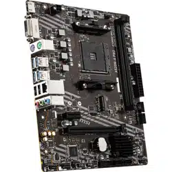
Thank you for purchasing the MSI® B550M PRO-VDH WIFI
motherboard. This Quick Start section provides demonstration
diagrams about how to install your computer. Some of the
installations also provide video demonstrations. Please link to the
URL to watch it with the web browser on your phone or tablet. You
may have even link to the URL by scanning the QR code.
B550M PRO-VDH WIFI
MSI® B550M PRO-VDH WIFI
B550M PRO-VDH WIFI
B550M PRO-VDH WIFI
II
Quick Start
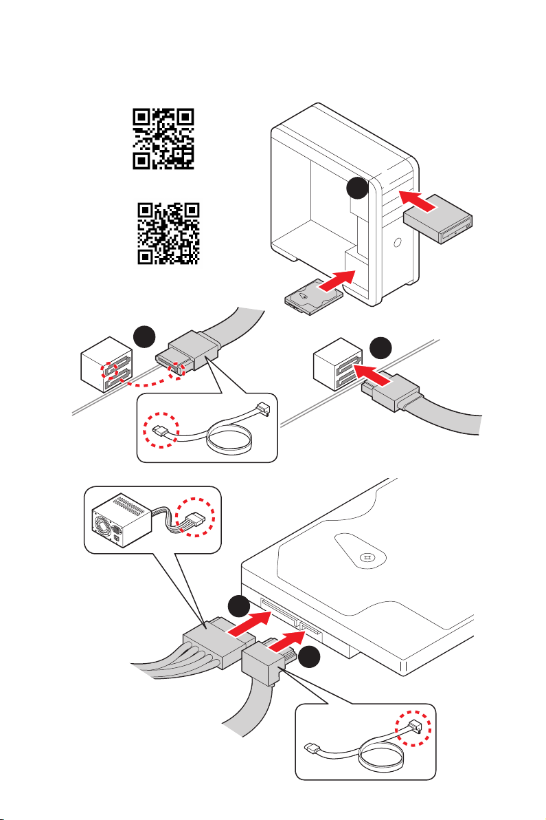
1
2
3
6
4
5
7
8
9
Youtube
http://v.youku.com/v_show/id_
XMTg2MjMwOTE2NA==.html
https://youtu.be/Xv89nhFk1vc
III
Quick Start
1
2
3
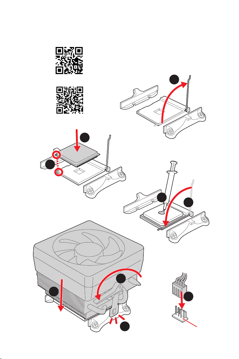
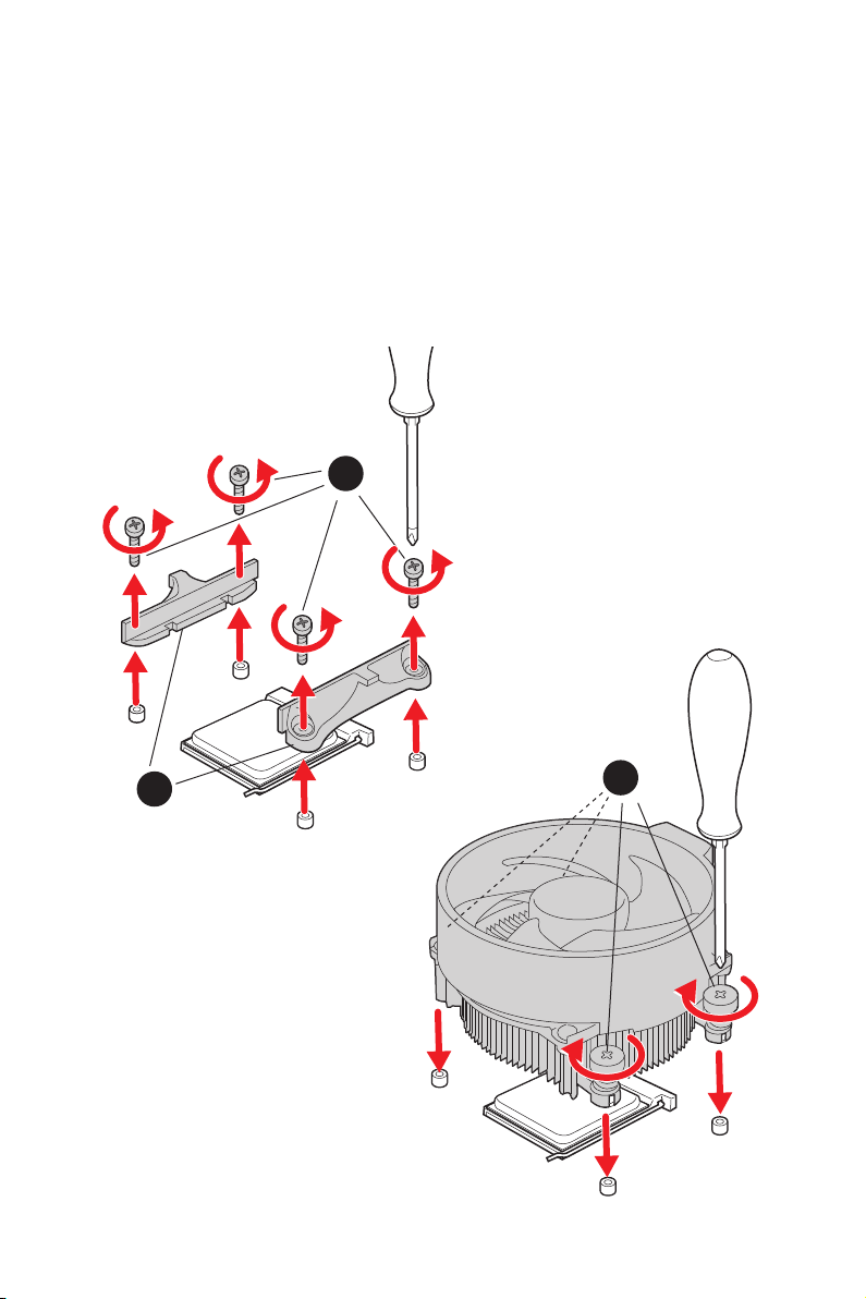
Important
remove the retention module first and then install the heatsink.
IV
Quick Start
DIMMA2 DIMMA2
DIMMB2
DIMMA1
DIMMA2
DIMMB1
DIMMB2
http://youtu.be/T03aDrJPyQs
Youtube
http://v.youku.com/v_show/id_XNzUyMTI5ODI4.html
V
Quick Start
Connecting the Front Panel Header/
http://youtu.be/DPELIdVNZUI
Youtube
http://v.youku.com/v_show/id_XNjcyMTczMzM2.html
HDD LED
RESET SW
HDD LED
HDD LED -
HDD LED +
POWER LED -
POWER LED +
POWER LED
1
2 10
9
+
+
+-
--
-
+
Power LED
HDD LED Reset Switch
Reserved
Power Switch
JFP1
1 HDD LED + 2 Power LED +
3 HDD LED - 4 Power LED -
5 Reset Switch 6 Power Switch
7 Reset Switch 8 Power Switch
9 Reserved 10 No Pin
RESET SW
POWER SW
POWER LED+
POWER LED-
HDD LED
JFP1
VI
Quick Start
BAT1
2
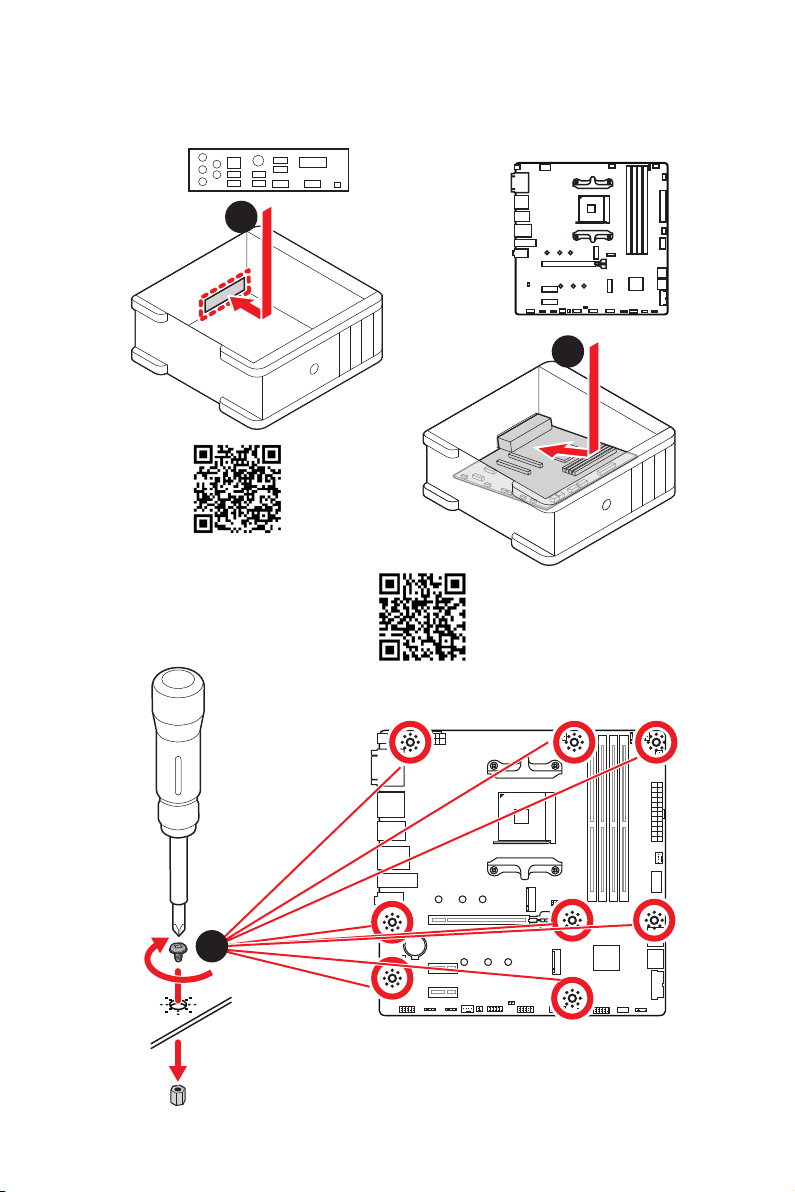
Torque:
3 kgf·cm*
*3 kgf·cm
= 0.3 N·m
= 2.6 lbf·in
2
1
https://youtu.be/wWI6Qt51Wnc
Youtube
https://v.youku.com/v_show/id_
XNDUwMDUyNTkwOA==.html
VII
Quick Start
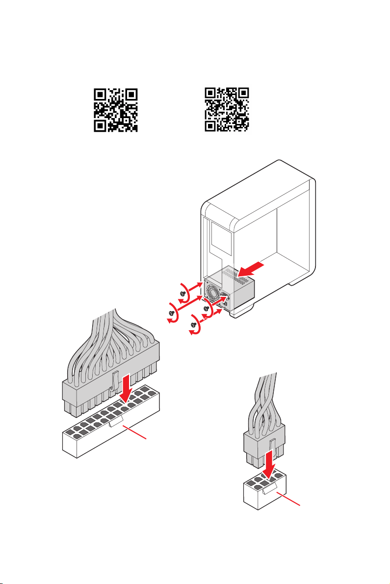
ATX_PWR1
http://youtu.be/gkDYyR_83I4 http://v.youku.com/v_show/id_XNDkzODU0MDQw.html
Youtube
VIII
Quick Start
http://youtu.be/RZsMpqxythc
Youtube
http://v.youku.com/v_show/
id_XNDkzODU5MTky.html
1
2
3
4
5
IX
Quick Start
http://youtu.be/mG0GZpr9w_A
http://v.youku.com/v_show/
id_XNDkyOTc3MzQ4.html
Youtube
1
2
3
4
5
6
X
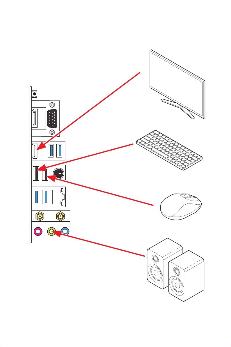
Quick Start
Processor with integrated graphics
XI
Quick Start
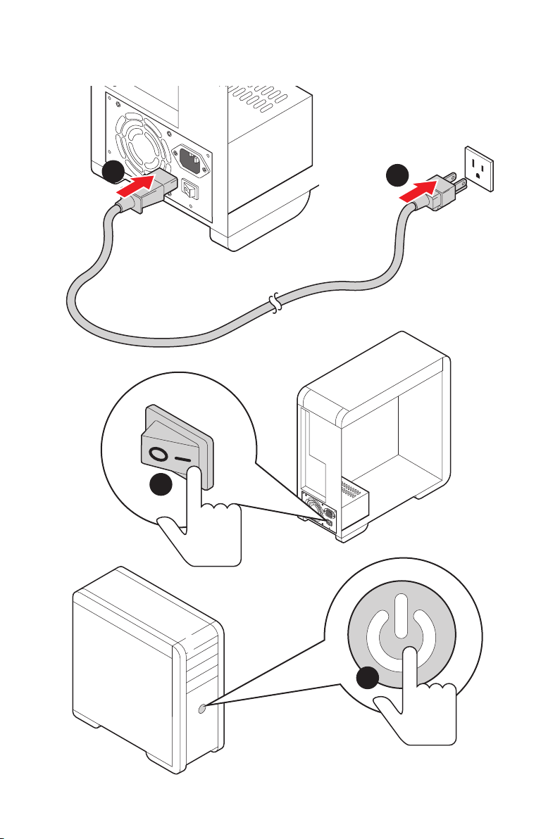
4
3
1
2

XII
Quick Start
NOTE

1
Contents
Contents
Safety Information ................................................................................................. 2
Specifications ......................................................................................................... 3
Package contents .................................................................................................. 8
Rear I/O Panel ....................................................................................................... 9
LAN Port LED Status Table .................................................................................... 9
........................................................................................... 9
Overview of Components .................................................................................... 12
Processor Socket ................................................................................................. 13
DIMM Slots ............................................................................................................ 14
.......................................................................... 15
....................................................................... 15
................................................................................... 16
................................................................... 18
............................................................................ 18
....................................................... 19
................................................. 20
............................................................. 20
............................................................................. 21
........................................................................... 21
.................................. 22
....................................................................... 23
........................................................... 24
............................................................................. 24
............................................................................. 25
............................................ 26
EZ Debug LED ....................................................................................................... 27
................................................................................... 27
Installing OS, Drivers & Utilities ......................................................................... 28
UEFI BIOS ............................................................................................................. 29
BIOS Setup ............................................................................................................ 30
Entering BIOS Setup ............................................................................................. 30
Resetting BIOS ...................................................................................................... 31
Updating BIOS ....................................................................................................... 31
EZ Mode ................................................................................................................ 33
Advanced Mode .................................................................................................... 36
................................................................................................................ 37

2
Safety Information
Safety Information
The components included in this package are prone to damage from electrostatic
computer assembly.
Ensure that all components are securely connected. Loose connections may cause
the computer to not recognize a component or fail to start.
Hold the motherboard by the edges to avoid touching sensitive components.
handling the motherboard to prevent electrostatic damage. If an ESD wrist strap is
before handling the motherboard.
Store the motherboard in an electrostatic shielding container or on an anti-static
pad whenever the motherboard is not installed.
components on the motherboard or anywhere within the computer case.
Do not boot the computer before installation is completed. This could cause
permanent damage to the components as well as injury to the user.
technician.
Always turn off the power supply and unplug the power cord from the power outlet
before installing or removing any computer component.
Make sure that your electrical outlet provides the same voltage as is indicated on
Place the power cord such a way that people can not step on it. Do not place
anything over the power cord.
All cautions and warnings on the motherboard should be noted.
personnel:
Liquid has penetrated into the computer.
The motherboard has been exposed to moisture.
The motherboard does not work well or you can not get it work according to user
guide.
The motherboard has been dropped and damaged.
The motherboard has obvious sign of breakage.
the motherboard.

3
Specifications
Specifications
CPU
future AMD Ryzen™ processors with BIOS update
Chipset
Memory
Supports DDR4 1866/ 2133/ 2400/ 2667/ 2800/ 2933/
Supports DDR4 2667/ 2800 /2933 /3000 /3066 /3200
/3466 /3600/ 3733 /3866 /4000 /4133 /4266 /4400+ MHz by
Dual channel memory architecture
Supports un-buffered memory
* Please refer www.msi.com for more information on compatible memory.
Expansion Slot
* The supported specification depends on installed processor.
Onboard Graphics
Maximum shared memo
ry of 16 GB
* Available for the processor with integrated graphics.

4
Specifications
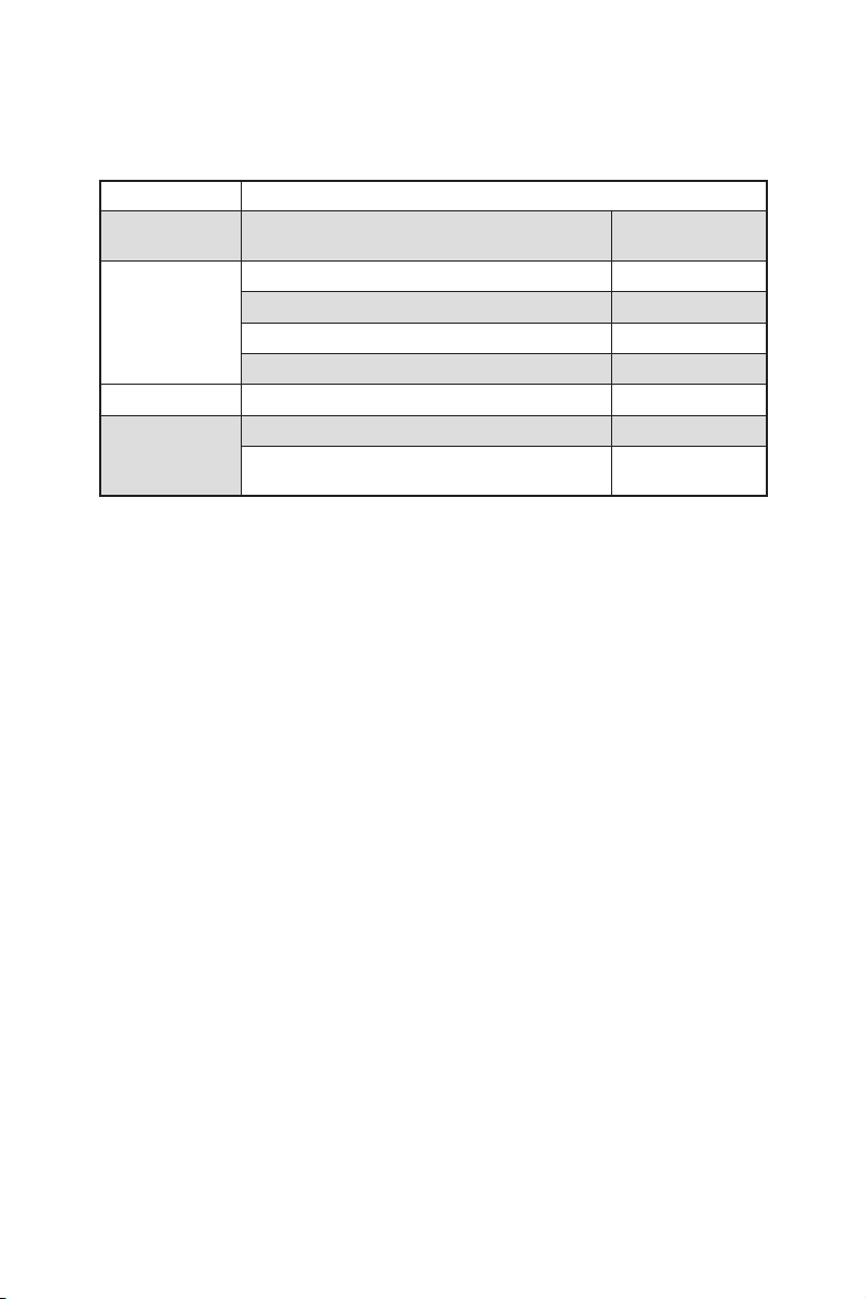
Storage
4x SATA 6Gb/s ports
Supports SATA 6Gb/s
Supports 2242/ 2260/ 2280 storage devices
Supports 2242/ 2260/ 2280 storage devices
* The supported specification depends on installed processor.
RAID
devices
Supports RAID 0 and RAID 1 for M.2 NVMe storage devices
USB
3x USB 3.2 Gen 1 5Gbps ports
AMD Processor
4x USB 3.2 Gen 1 5Gbps Type-A ports on the back
panel
Audio
LAN 1x Realtek® RTL8111HN 1Gbps LAN controller
Wireless LAN &
Bluetooth
®
Intel®

5
Specifications
Internal Connectors
1x 24-pin ATX main power connector
1x 8-pin ATX 12V power connector
4x SATA 6Gb/s connectors
1x 4-pin water-pump fan connector
3x 4-pin system fan connectors
1x Front panel audio connector
2x System panel connectors
1x Serial port connector
2x 4-pin RGB LED connectors
2x 3-pin RAINBOW LED connectors
1xTPM module connector
LED Features
4x EZ Debug LED
Back Panel
Connectors
1x Flash BIOS Button
1x VGA port
1x Display port
1x HDMI port
4x USB 3.2 Gen 1 5Gbps Type-A ports
1x PS/2 keyboard/ mouse combo port
2x USB 2.0 Type-A ports
2x Wi-Fi Antenna connectors
3x Audio jacks
6
Specifications
I/O Controller
Hardware Monitor
Form Factor
Micro-ATX Form Factor
BIOS Features
1x 256 Mb flash
UEFI AMI BIOS
Multi-language
Software
Drivers
Norton™ Internet Security Solution
Dragon Center
Features
Mystic Light
User Scenario
Hardware Monitor
Live Update
Speed Up
Smart Tool
Please refer to http://download.msi.
pdf for more details.

7
Specifications
Special Features
Audio
Audio Boost
Network
Intel WiFi
Pump Fan
LED
EZ DEBUG LED
Performance
DDR4 Boost
Protection
Experience
Flash BIOS Button
8
Package contents
Package contents
Please check the contents of your motherboard package. It should contain:
Motherboard B550M PRO-VDH WIFI
Cable
SATA 6G cables
1
Accessories
Wi-Fi antenna 1
1
1
Product registration card 1
Application Driver DVD 1
Documentation
Quick installation guide 1
MSI components compatibility & reward
program card
1
Important

9
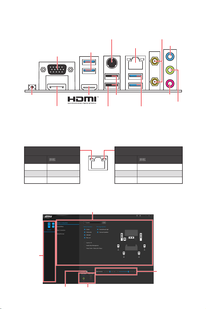
Rear I/O Panel
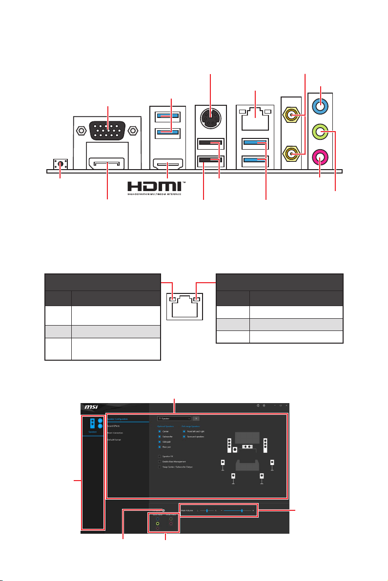
Rear I/O Panel
Flash BIOS Port/ Button - Please refer to page 32 for Updating BIOS with Flash
BIOS Button.
Link/ Activity LED
Status Description
Off No link
Yellow Linked
Blinking Data activity
Speed LED
Status Description
Off 10 Mbps connection
Green 100 Mbps connection
Orange 1 Gbps connection
LAN Port LED Status Table
Realtek Audio Console
better sound experience.
USB 3.2 Gen 1
USB 3.2 Gen 1
Flash BIOS
Port
1 Gbps LAN
DisplayPort
VGA
USB 2.0
Type-A
Wi-Fi Antenna
connectors
Flash BIOS Button
Line-In
Mic-In
Line-Out
Jack Status
Device
Selection
Main Volume
Application Enhancement
10
Rear I/O Panel
Device Selection - allows you to select a audio output source to change the related
options. The check sign indicates the devices as default.
Application Enhancement - the array of options will provide you a complete
guidance of anticipated sound effect for both output and input device.
Main Volume - controls the volume or balance the right/left side of the speakers
that you plugged in front or rear panel by adjust the bar.
Jack Status - depicts all render and capture devices currently connected with your
computer.
Connector Settings - configures the connection settings.
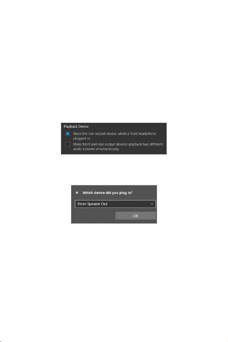
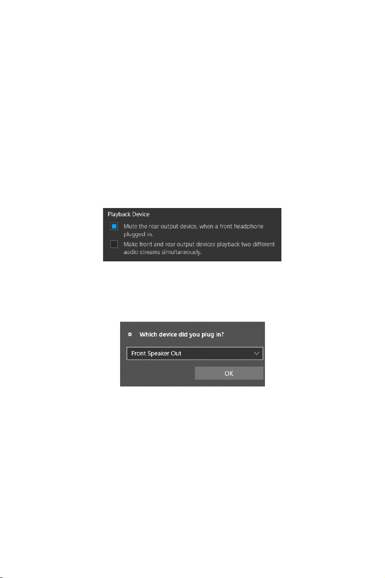
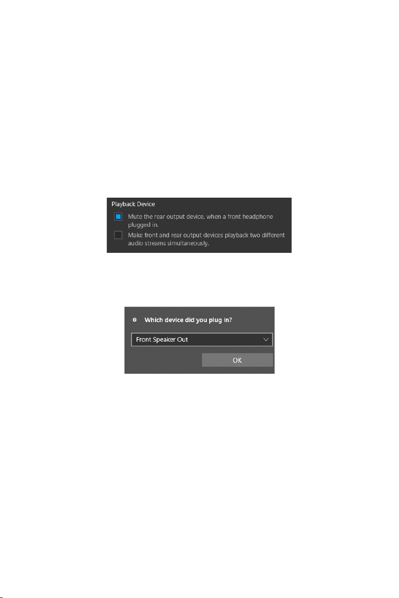
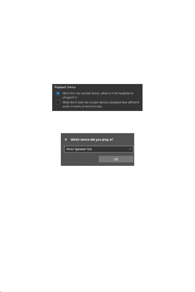
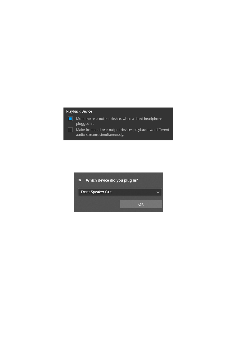
Audio 7.1-channel Configuration
connector and follow the below steps.
1.
below.
2. Select Mute the rear output device, when a front headphone plugged in.
3. Plug your speakers to audio jacks on rear and front I/O panel. When you plug a
current connected.
Important
The pictures above for reference only and may vary from the product you purchased.

11
Rear I/O Panel
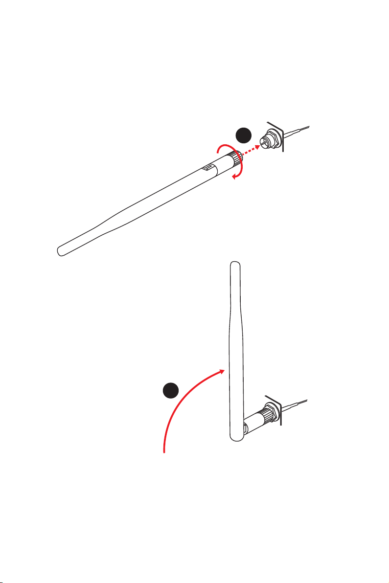
Installing antennas
1.
Screw the antennas tight to the antenna connectors as shown below.
2. Orient the antennas.
1
2

12
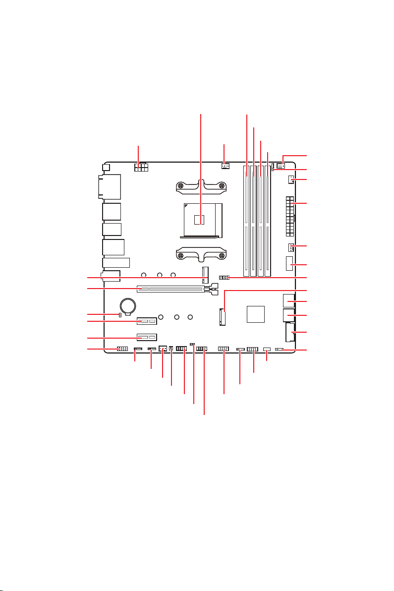
Overview of Components
Overview of Components
BAT1
JUSB3
LED_SW1
JRGB2
JRGB1
M2_1
JUSB1
JTPM1
JUSB2
JRAINBOW1
M2_2
SYS_FAN2
SYS_FAN1
JBAT1
Processor Socket
PUMP_FAN1
JRAINBOW2
JAUD1
JUSB4
JFP1
JSMB1
SYS_FAN3
JFP2
ATX_PWR1
DIMMB1
DIMMB2
DIMMA1
DIMMA2

13
Overview of Components
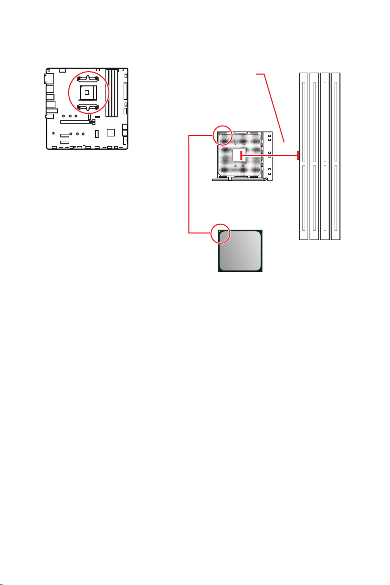
Processor Socket
Introduction to the AM4 CPU
yellow triangle to assist in correctly
placement. The yellow triangle is
the Pin 1 indicator.
53.8 mm
Distance from the center of the
CPU to the nearest DIMM slot.
Important
Always unplug the power cord from the power outlet before installing or removing
is necessary to prevent overheating and maintain system stability.
your system.
enhance heat dissipation.
documentation in the heatsink/ cooler package for more details about installation.
This motherboard is designed to support overclocking. Before attempting to
overclocking. Any attempt to operate beyond product specifications is not
recommended. MSI
®
does not guarantee the damages or risks caused by inadequate
operation beyond product specifications.

14
Overview of Components
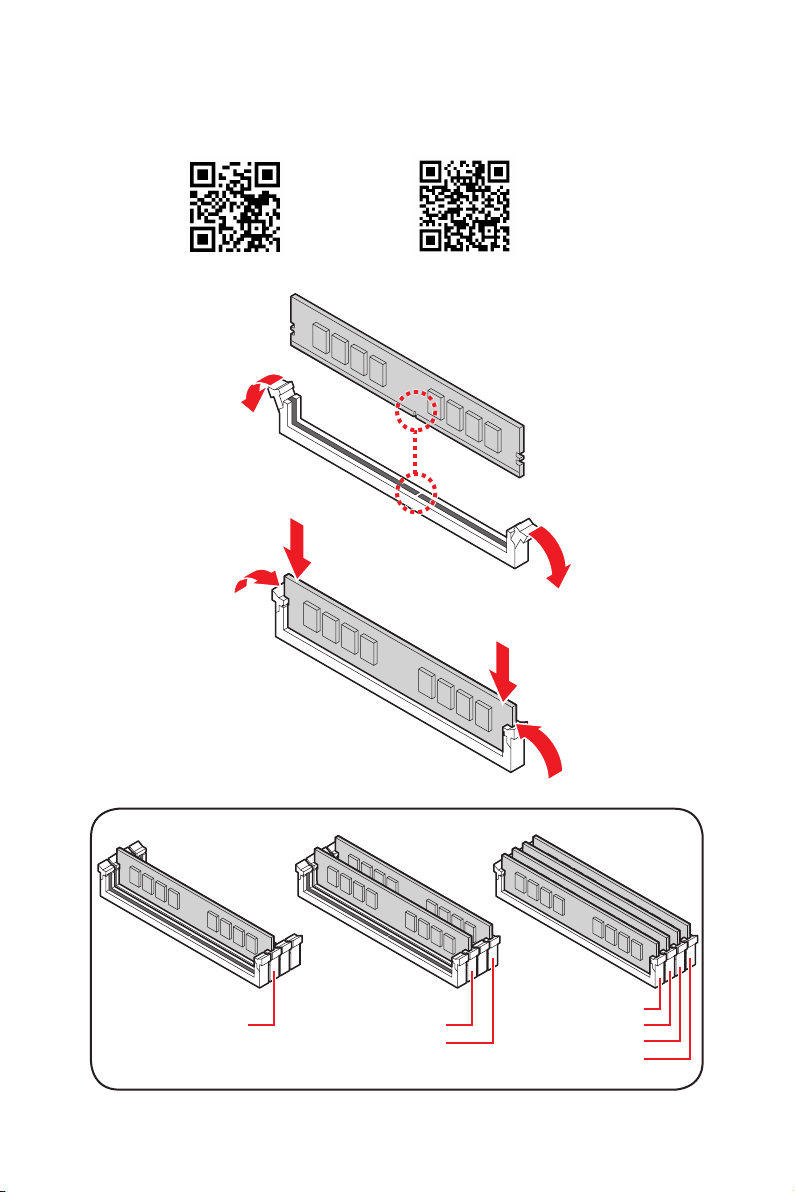
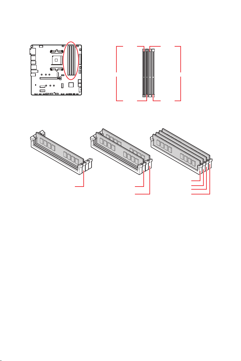
DIMM Slots
DIMMA1 DIMMB1
Channel A Channel B
DIMMA2 DIMMB2
Memory module installation recommendation
Important
Always insert memory modules in the DIMMA2 slot first.
than the amount of installed.
Some memory modules may operate at a lower frequency than the marked value
when overclocking due to the memory frequency operates dependent on its Serial
DRAM Frequency to set the memory
frequency if you want to operate the memory at the marked or at a higher frequency.
It is recommended to use a more efficient memory cooling system for full DIMMs
installation or overclocking.
and devices when overclocking.
Please refer www.msi.com for more information on compatible memory.
DIMMB2 DIMMB2
DIMMB1
DIMMA2
DIMMA2
DIMMA2
DIMMA1

15
Overview of Components
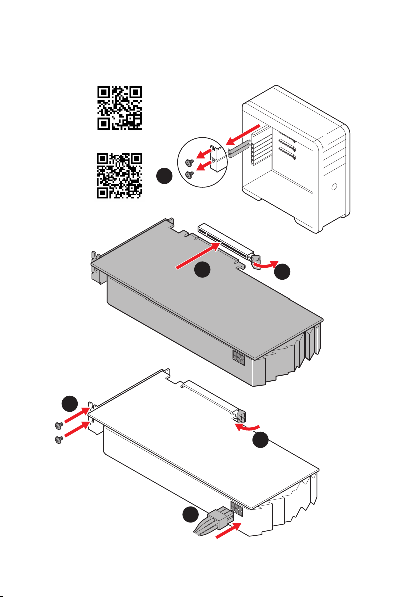
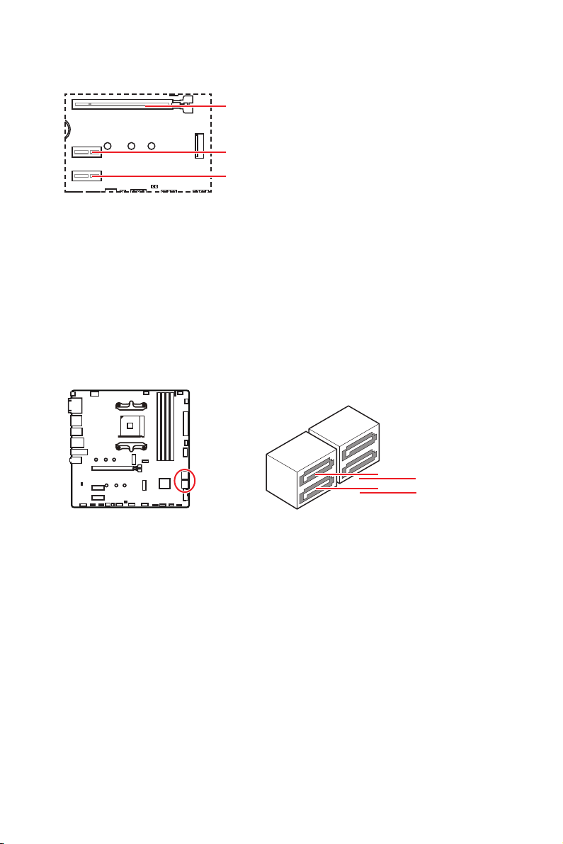
PCI_E1~3: PCIe Expansion Slots
Important
MSI
Gaming Series Graphics Card Bolster to support its weight to prevent deformation of
the slot.
unplug the power supply power cable from the power outlet. Read the expansion
changes.
T1
PCI_E1
PCI_E3
PCI_E2
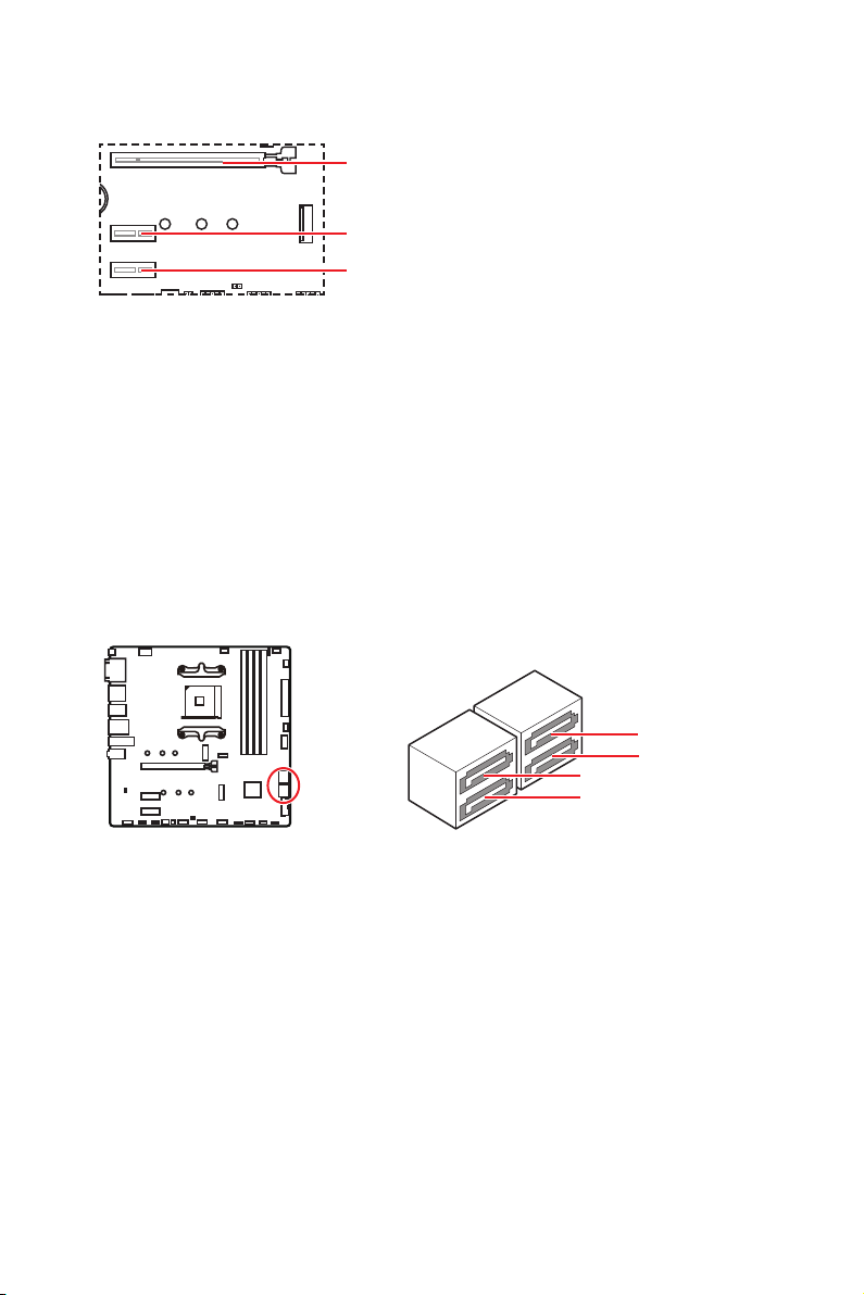
SATA1~4: SATA 6Gb/s Connectors
These connectors are SATA 6Gb/s interface ports. Each connector can connect to one
SATA device.
Important
Please do not fold the SATA cable at a 90-degree angle. Data loss may result during
transmission otherwise.
recommended that the flat connector be connected to the motherboard for space
saving purposes.
SATA1
SATA3
SATA2
SATA4
16
Overview of Components
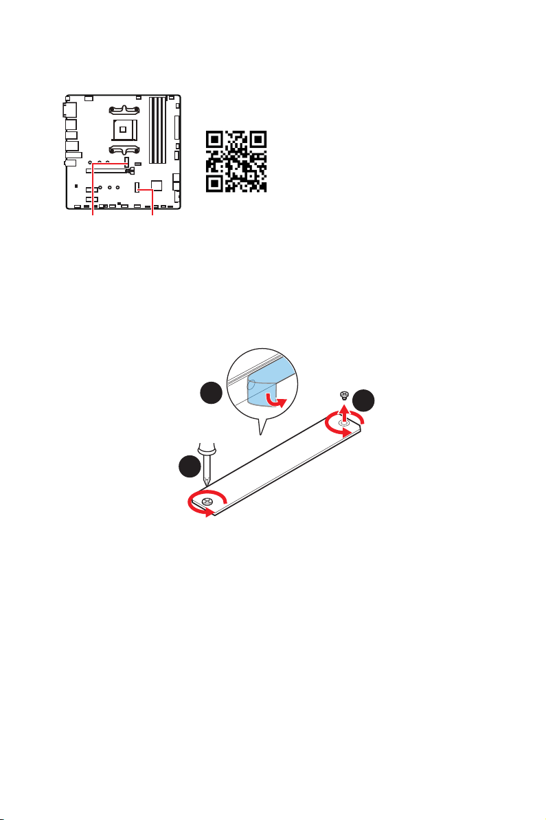
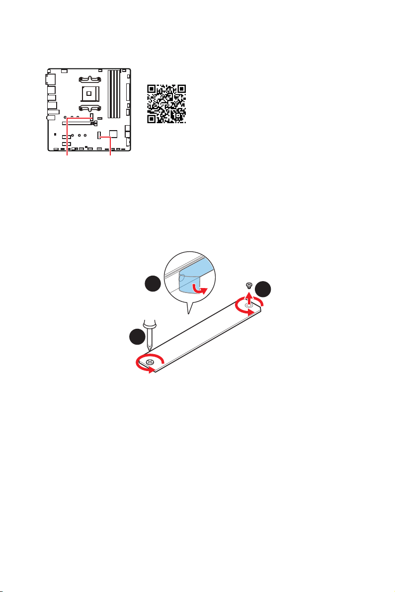
M2_1~2: M.2 Slots (Key M)
M2_1 M2_2
Video Demonstration
Watch the video to learn how to Install
M.2 module.
M2_1 slot installation
1.
Loosen the screws of M.2 SHIELD FROZR heatsink.
2. Remove the M.2 SHIELD FROZR and remove the protective films from the thermal
pads.
1
1
2

17
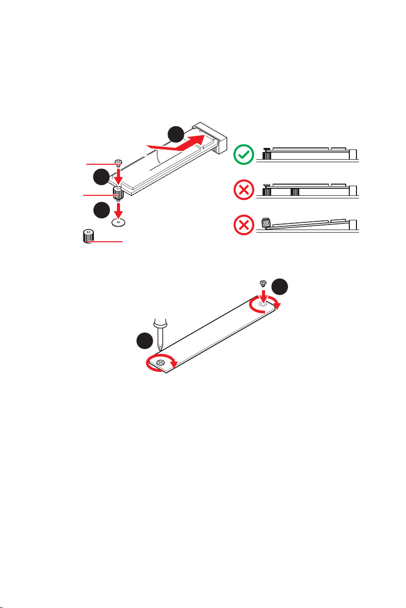
Overview of Components
30º30º
M.2 standoff
heatsink standoff
3
5
4
M.2 screw
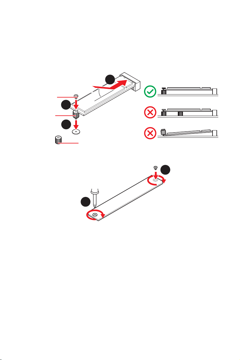
M2_2 slot installation
1.
Move the position of the standoffs according to your M.2 SSDs length if need.
2. Insert your M.2 SSD into the M.2 slot at a 30-degree angle.
3. Secure the M.2 SSD in place with the supplied M.2 screw.
3.
or remove the M.2 standoff if your M.2 SSD length is same as the length of M.2
heatsink to avoid damage to the M.2 SSD.
4. Insert your M.2 SSD into the M.2 slot at a 30-degree angle.
5.
M.2 standoff in step 3.
6. Put the M.2 SHIELD FROZR heatsink back in place and secure it.
6
6

18
Overview of Components
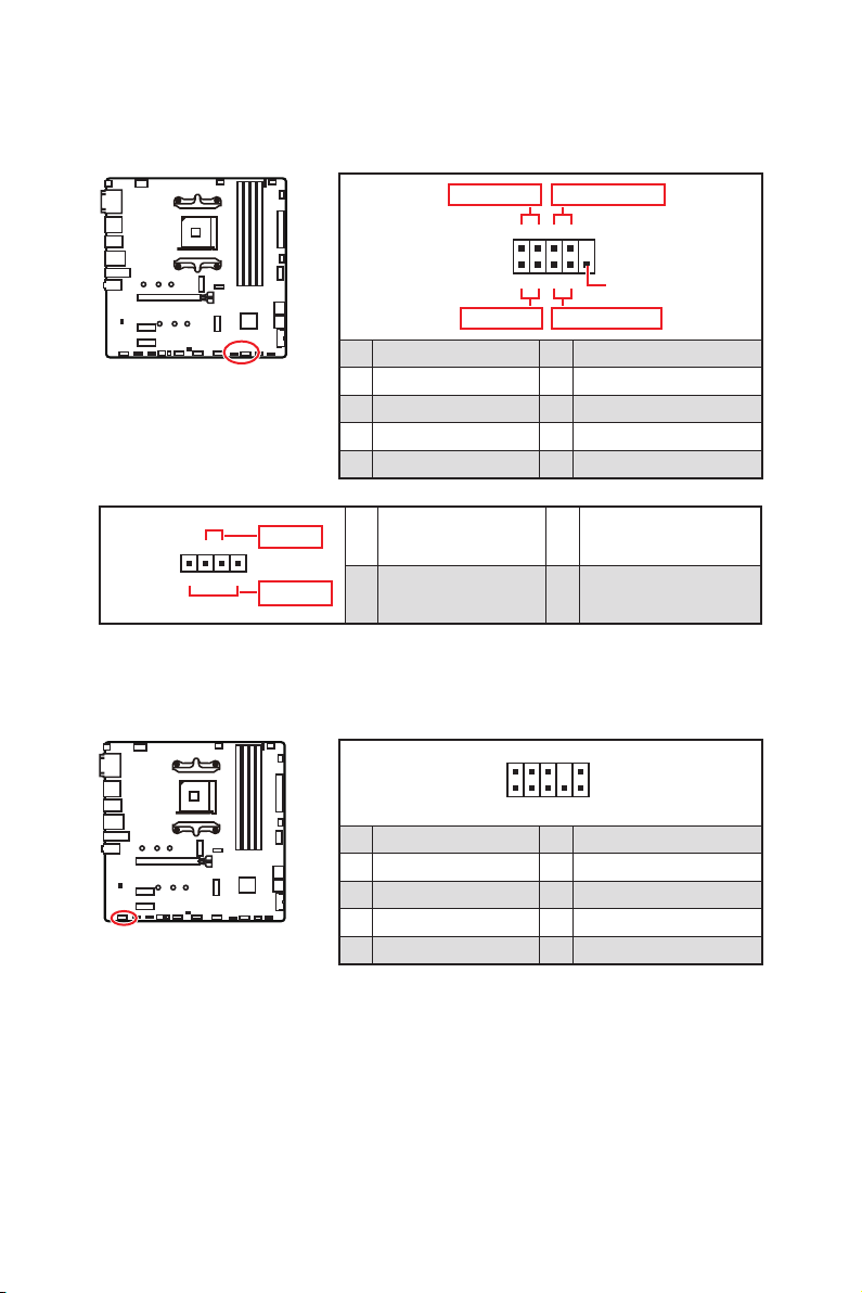
JAUD1: Front Audio Connector
This connector allows you to connect audio jacks on the front panel.
1
2 10
9
1 2 Ground
3 4
5 Head Phone R 6
7 SENSE_SEND 8 No Pin
9 Head Phone L 10 Head Phone Detection
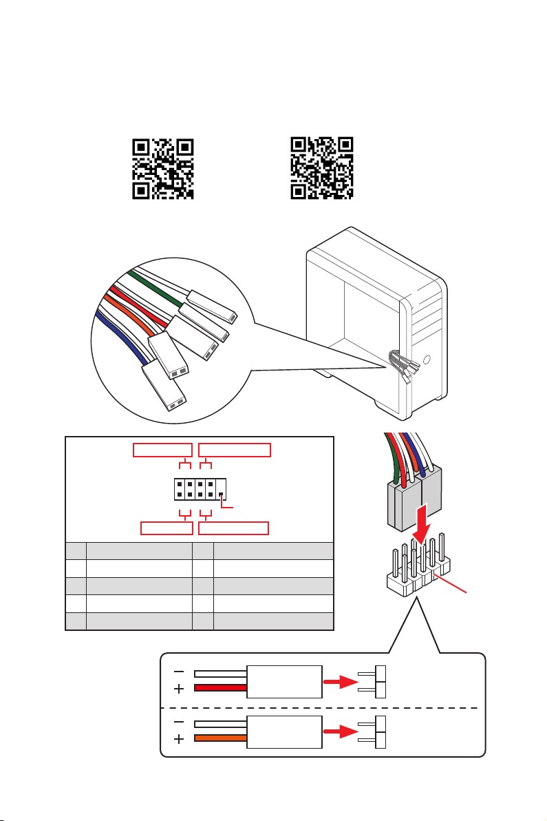
JFP1, JFP2: Front Panel Connectors
These connectors connect to the switches and LEDs on the front panel.
1
JFP2
+
+
-
-
Speaker
Buzzer
1 Speaker - 2 Buzzer +
3 Buzzer - 4 Speaker +
1
2 10
9
+
+
+-
--
-
+
Power LED
HDD LED Reset Switch
Reserved
Power Switch
JFP1
1 HDD LED + 2 Power LED +
3 HDD LED - 4 Power LED -
5 Reset Switch 6 Power Switch
7 Reset Switch 8 Power Switch
9 Reserved 10 No Pin
19
Overview of Components
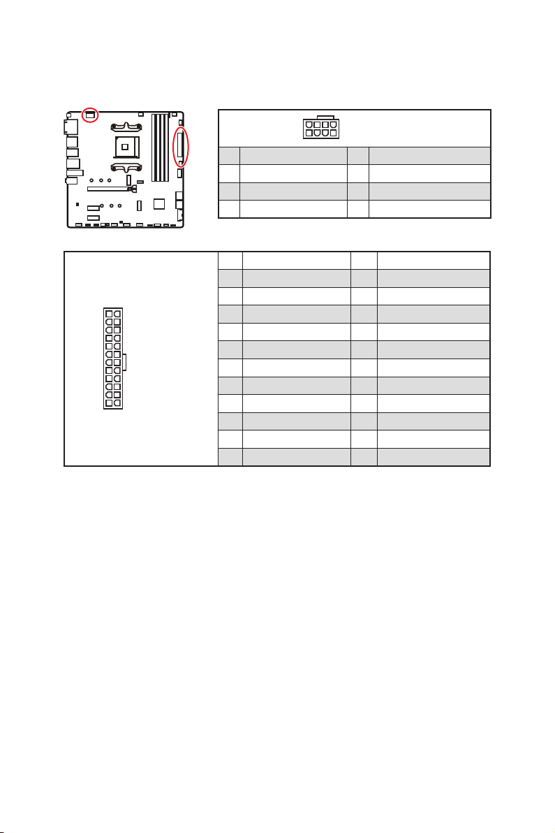
24
131
12
ATX_PWR1
1 +3.3V 13 +3.3V
2 +3.3V 14 -12V
3 Ground 15 Ground
4 +5V 16 PS-ON#
5 Ground 17 Ground
6 +5V 18 Ground
7 Ground 19 Ground
8 20 Res
9 5VSB 21 +5V
10 +12V 22 +5V
11 +12V 23 +5V
12 +3.3V 24 Ground
5
4 1
8
1 Ground 5 +12V
2 Ground 6 +12V
3 Ground 7 +12V
4 Ground 8 +12V
Important
Make sure that all the power cables are securely connected to a proper ATX power
supply to ensure stable operation of the motherboard.
CPU_PWR1, ATX_PWR1: Power Connectors
These connectors allow you to connect an ATX power supply.

20
Overview of Components
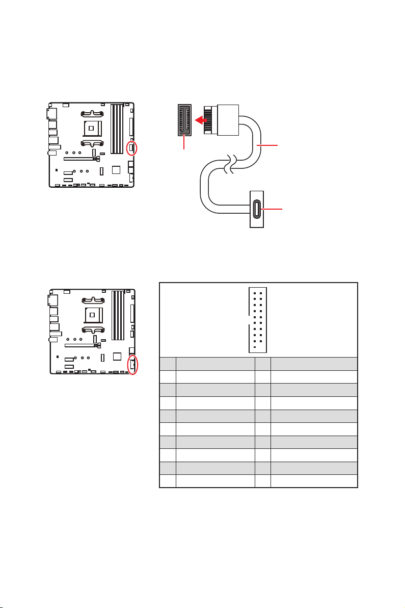
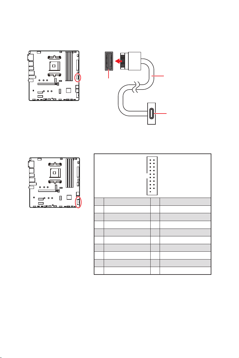
JUSB1: USB 3.2 Gen 1 5Gbps Type-C Connector
be sure to connect it with the corresponding orientation.
JUSB2: USB 3.2 Gen 1 5Gbps Connector
This connector allows you to connect USB 3.2 Gen 1 5Gbps ports on the front panel.
Important
Note that the Power and Ground pins must be connected correctly to avoid possible
damage.
1
10 11
20
1 Power 11 USB2.0+
2 USB3_RX_DN 12 USB2.0-
3 USB3_RX_DP 13 Ground
4 Ground 14
5 15
6 16 Ground
7 Ground 17 USB3_RX_DP
8 USB2.0- 18 USB3_RX_DN
9 USB2.0+ 19 Power
10
Ground 20 No Pin
JUSB1
the front panel
21
Overview of Components
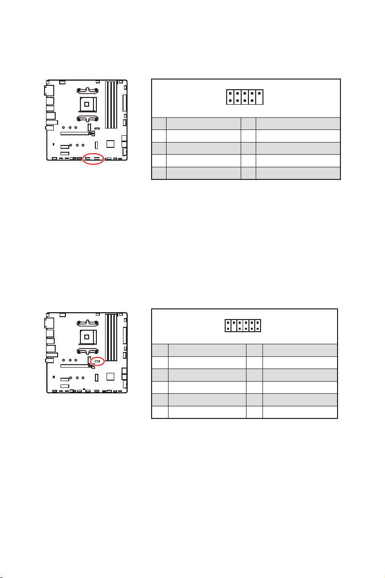
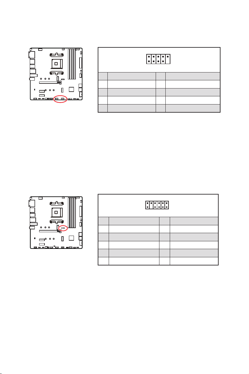
JUSB3~4: USB 2.0 Connectors
These connectors allow you to connect USB 2.0 ports on the front panel.
1
2 10
9
1 2
3 USB0- 4 USB1-
5 USB0+ 6 USB1+
7 Ground 8 Ground
9 No Pin 10
Important
damage.
MSI
®
1
212
11
1 SPI Power 2
3
4
5 Reserved 6
7 Ground 8 SPI Reset
9 Reserved 10 No Pin
11 Reserved 12 Interrupt Request
JTPM1: TPM Module Connector
platform manual for more details and usages.
22
Overview of Components
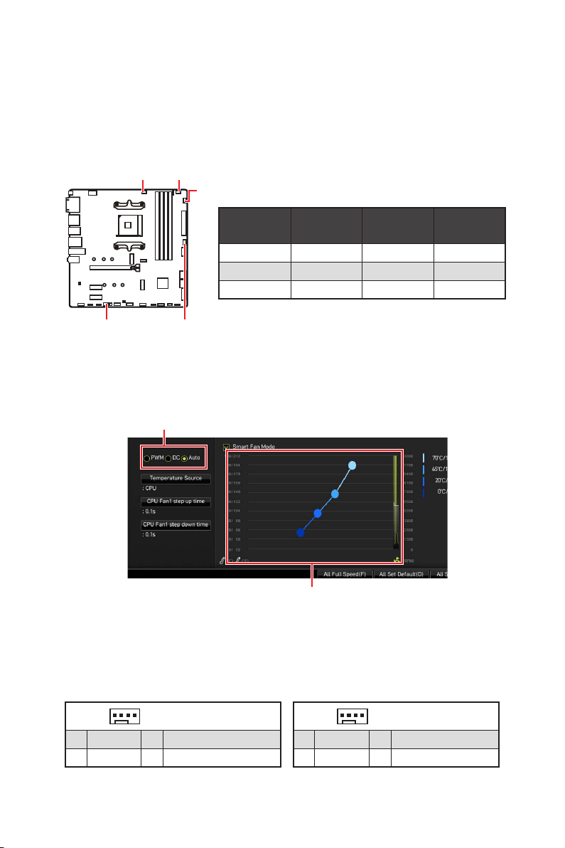
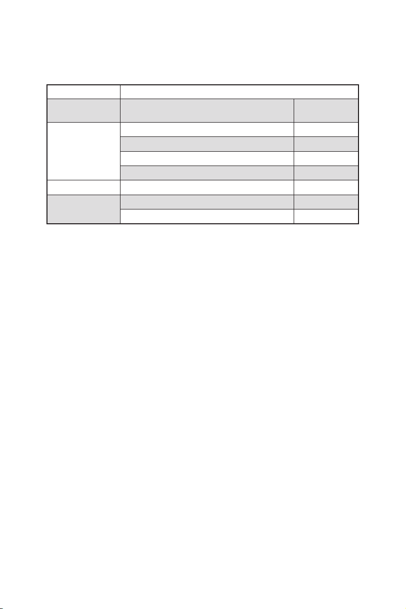
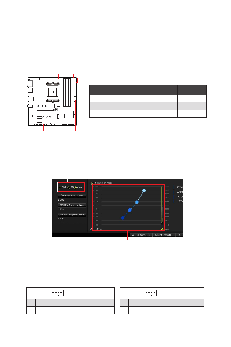
CPU_FAN1, PUMP_FAN1, SYS_FAN1~3: Fan Connectors
PWM Mode fan connectors provide constant 12V output and adjust fan speed with
manually.
Switching fan mode and adjusting fan speed
BIOS >
HARDWARE MONITOR.
Select PWM mode or DC mode
Important
There are gradient points of the fan speed that allow you to adjust
Pin definition of fan connectors
SYS_FAN3
PUMP_FAN1
SYS_FAN1
SYS_FAN2
Connector
Default fan
mode
Max.
current
Max.
power
Auto mode 2A 24W
PUMP_FAN1 PWM mode 3A 36W
1A 12W
1
PWM Mode pin definition
1 Ground 2 +12V
3 Sense 4
1
DC Mode pin definition
1 Ground 2
3 Sense 4

23
Overview of Components
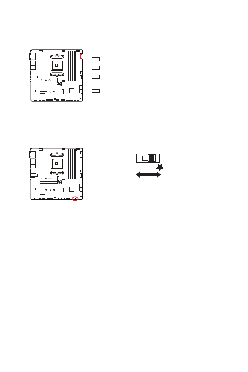
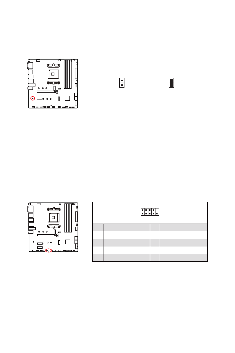
JCI1: Chassis Intrusion Connector
This connector allows you to connect the chassis intrusion switch cable.
Normal
Trigger the chassis
intrusion event
Using chassis intrusion detector
1.
JCI1 connector to the chassis intrusion switch/ sensor on the chassis.
2.
3. Go to BIOS > SETTINGS > Security > Chassis Intrusion Configuration.
4. Set Chassis Intrusion to Enabled.
5. Press F10 to save and exit and then press the Enter key to select Yes.
6.
screen when the computer is turned on.
Resetting the chassis intrusion warning
1.
Go to BIOS > SETTINGS > Security > Chassis Intrusion Configuration.
2. Set Chassis Intrusion to Reset.
3. Press F10 to save and exit and then press the Enter key to select Yes.

24
Overview of Components
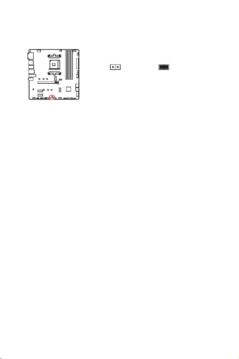
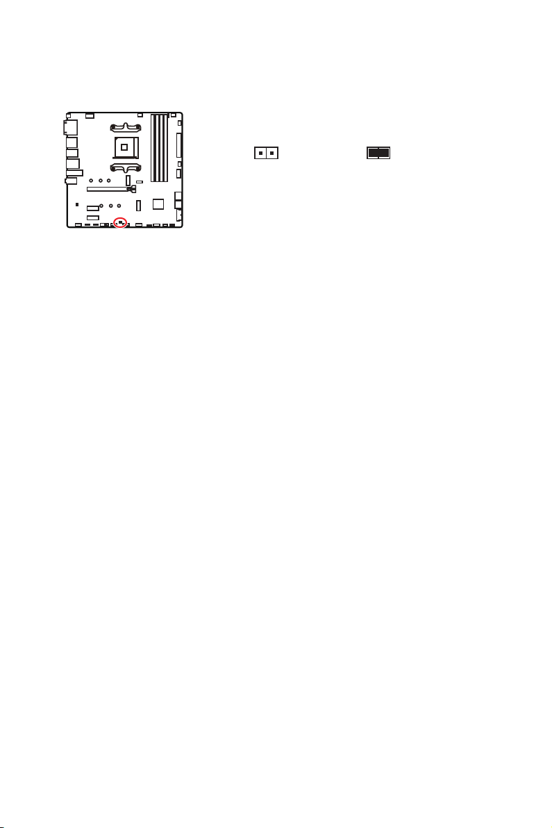
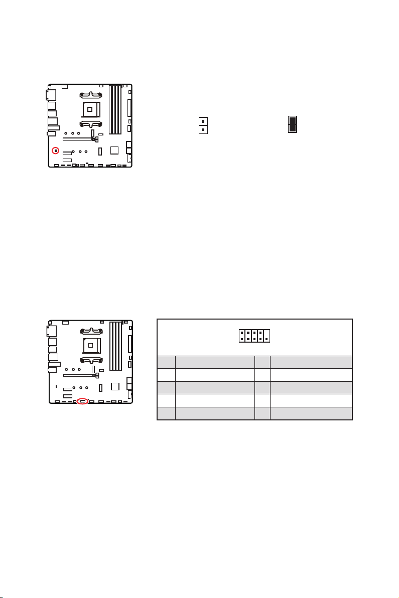
JBAT1: Clear CMOS (Reset BIOS) Jumper
the motherboard to save system configuration data. If you want to clear the system
Reset BIOS
Resetting BIOS to default values
1.
Power off the computer and unplug the power cord.
2. Use a jumper cap to short JBAT1 for about 5-10 seconds.
3. Remove the jumper cap from JBAT1.
4. Plug the power cord and Power on the computer.
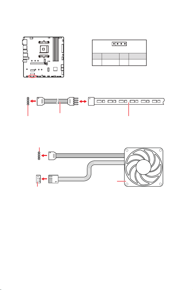
1
2 10
9
1 2 SIN
3 SOUT 4 DTR
5 Ground 6 DSR
7 RTS 8
9 RI 10 No Pin
JCOM1: Serial Port Connector
This connector allows you to connect the optional serial port with bracket.

25
Overview of Components
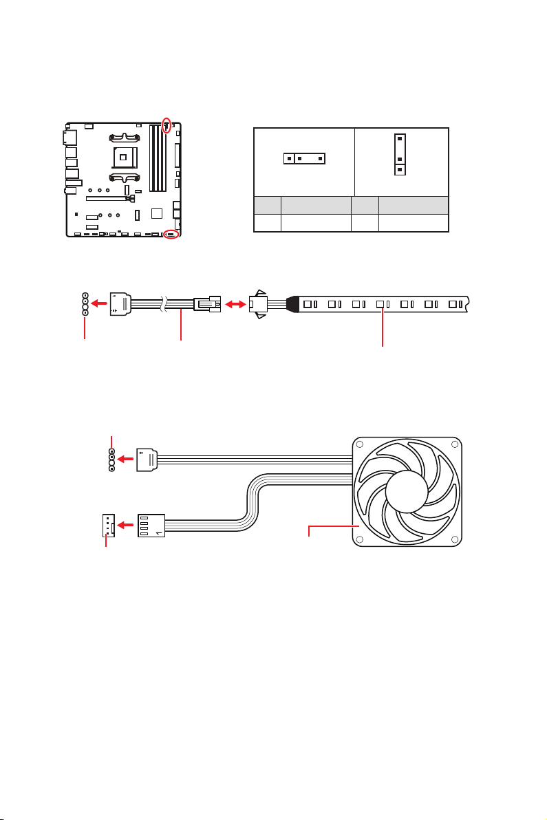
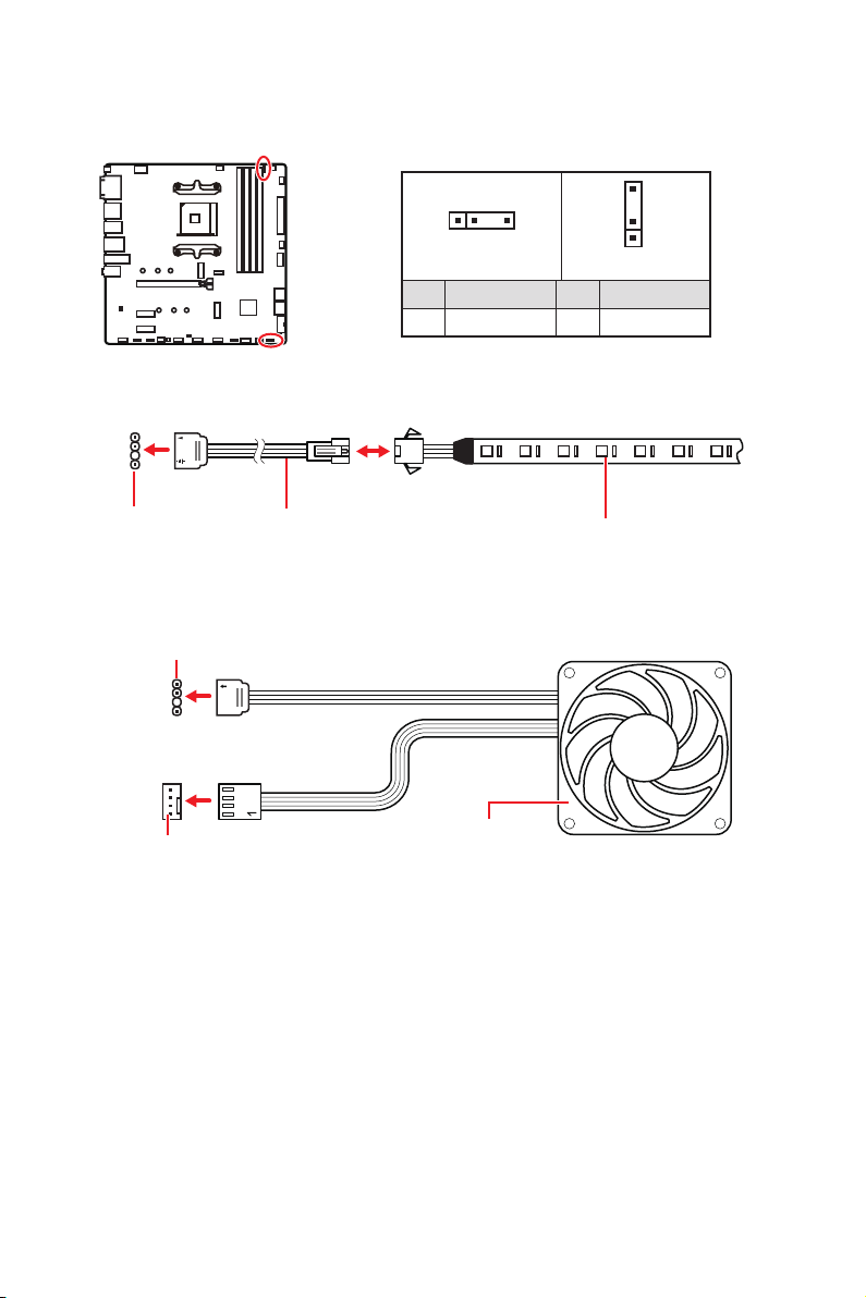
Important
The JRGB connector supports up to 2 meters continuous 5050 RGB LED strips
Always turn off the power supply and unplug the power cord from the power outlet
before installing or removing the RGB LED strip.
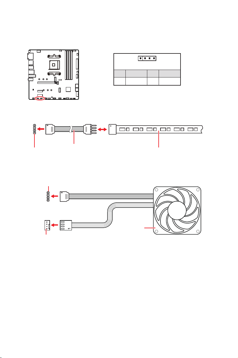
JRGB1~2: RGB LED connector
The JRGB connectors allow you to connect the 5050 RGB LED strips 12V.
1
G
R
B
JRGB
connector
RGB extension
cable
5050 RGB LED strips 12V
1
1 +12V 2 G
3 R 4 B
RGB LED Strip Connection
1
1
G
R
B
JRGB connector
System Fan connector
RGB LED Fan Connection
RGB LED Fan
26
Overview of Components
1
1
1
D
+5V
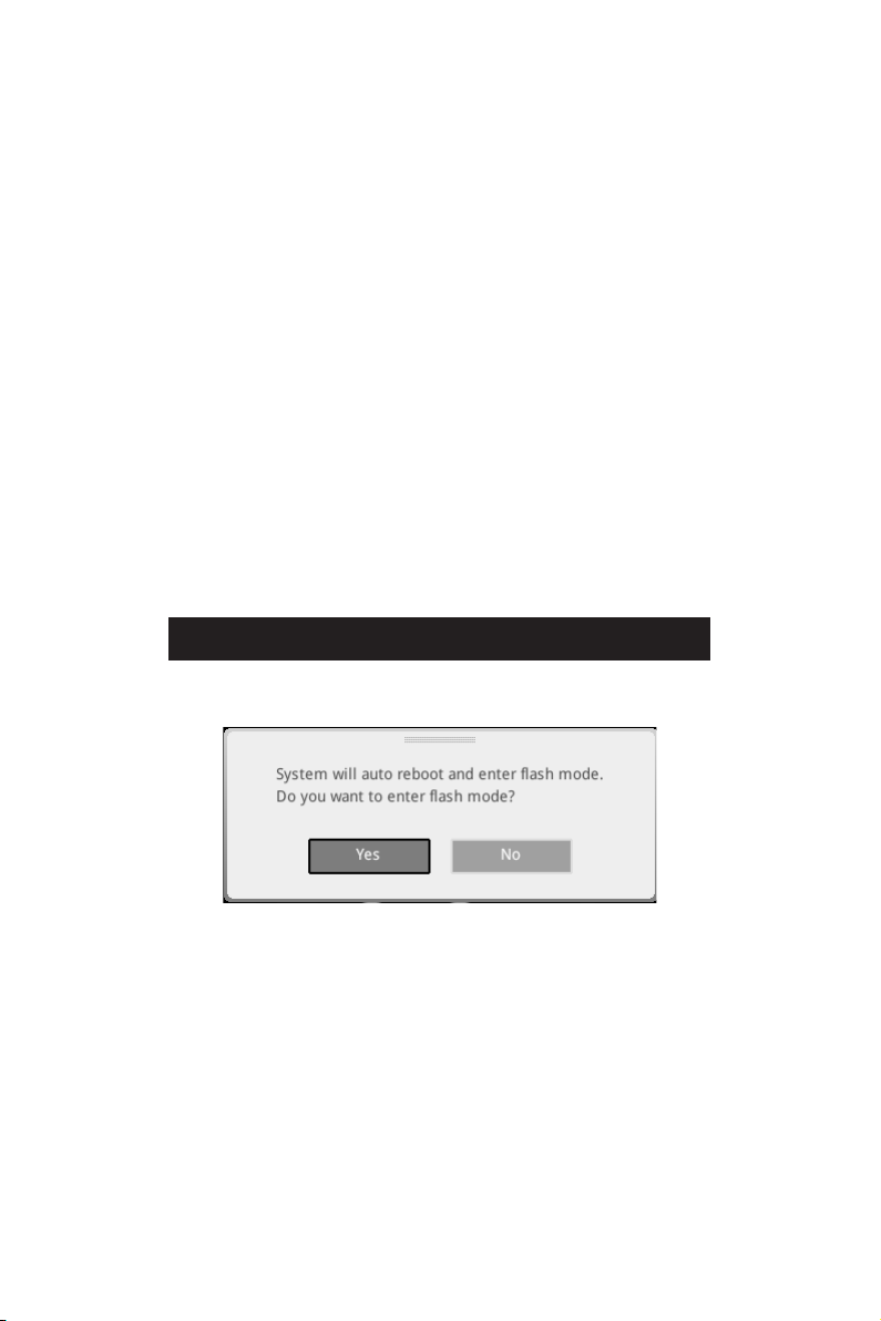
CAUTION
Do not connect the wrong type of LED strips. The JRGB connector and the JRAINBOW
connector will result in damage to the LED strip.
Important
The JRAINBOW connector supports up to 75 LEDs WS2812B Individually
Always turn off the power supply and unplug the power cord from the power outlet
before installing or removing the RGB LED strip.
JRAINBOW1~2: Addressable RGB LED connectors
The JRAINBOW connectors allow you to connect the WS2812B Individually
Addressable RGB LED strips 5V.
JRAINBOW
connector
JRAINBOW connector
System Fan connector
Rainbow RGB LED
extension cable
WS2812B Individually
Addressable RGB LED strips 5V
1
JRAINBOW1
1
JRAINBOW2
1 +5V 2 Data
3 No Pin 4 Ground
Addressable RGB LED Strip Connection
Addressable RGB LED Fan Connection
Addressable RGB LED Fan
27
Overview of Components
EZ Debug LED
These LEDs indicate the debug status of the motherboard.
CPU
DRAM - indicates DRAM is not detected or fail.
VGA
or fail.
BOOT - indicates the booting device is not detected
or fail.
LED_SW1: EZ LED Control
This switch is used to switch on/ off all the LEDs of motherboard.
LED_OFF
LED_ON

28
Installing OS, Drivers & Utilities
Installing OS, Drivers & Utilities
Please download and update the latest utilities and drivers at www.msi.com
Installing Windows® 10
1.
Power on the computer.
2. Insert the Windows® 10 installation disc/USB into your computer.
3. Press the Restart button on the computer case.
4. Press F11
Menu.
5. Select the Windows® 10 installation disc/USB from the Boot Menu.
6. Press any key when screen shows Press any key to boot from CD or DVD...
message.
7. Follow the instructions on the screen to install Windows® 10.
Installing Drivers
1.
Start up your computer in Windows® 10.
2. Insert MSI® Drive Disc into your optical drive.
3. Select to choose what happens with this disc
select Run DVDSetup.exe to open the installer. If you turn off the AutoPlay feature
DVDSetup.exe
from the root path of the MSI Drive Disc.
4. The installer will find and list all necessary drivers in the Drivers/Software tab.
5. Install button in the lower-right corner of the window.
6.
you to restart.
7. OK button to finish.
8. Restart your computer.
Installing Utilities
1. Open the installer as described above.
2. Utilities tab.
3. Select the utilities you want to install.
4. Install button in the lower-right corner of the window.
5.
you to restart.
6. OK button to finish.
7. Restart your computer.

29
UEFI BIOS
UEFI BIOS
architecture. UEFI has many new functions and advantages that traditional BIOS
compatible with older devices. That allows you to replace legacy devices with UEFI
compatible devices during the transition.
Important
The term BIOS in this user guide refers to UEFI BIOS unless otherwise noted.
UEFI advantages
Fast booting - UEFI can directly boot the operating system and save the BIOS self-
Supports for hard drive partitions larger than 2 TB.
Supports unlimited number of partitions.
Supports full capabilities of new devices - new devices may not provide backward
compatibility.
Supports secure startup - UEFI can check the validity of the operating system to
ensure that no malware tampers with the startup process.
Incompatible UEFI cases
32-bit Windows operating system - this motherboard supports only Windows 10
64-bit operating system.
Older graphics card - the system will detect your graphics card. When display a
warning message There is no GOP (Graphics Output protocol) support detected in
this graphics card.
Important
We recommend that you to use a GOP/ UEFI compatible graphics card.
How to check the BIOS mode?
CPU Temperature:
Motherboard Temperature:
VCore:
DDR Voltage:
BIOS Mode:
UEFI/CSM
CPU Temperature:
Motherboard Temperature:
VCore:
DDR Voltage:
BIOS Mode: UEFI/
CSM
UEFI boot mode CSM boot mode

30
UEFI BIOS
BIOS Setup
The default settings offer the optimal performance for system stability in normal
conditions. You should always keep the default settings to avoid possible system
damage or failure booting unless you are familiar with BIOS.
Important
description may be slightly different from the latest BIOS and should be for reference
only. You could also refer to the HELP information panel for BIOS item description.
The pictures in this chapter are for reference only and may vary from the product
you purchased.
The BIOS items will vary with the processor.
Entering BIOS Setup
Press Delete Press DEL key to enter Setup Menu, F11 to enter Boot
Menu message appears on the screen during the boot process.
Function key
F1: General Help list
F2: Add/ Remove a favorite item
F3: Enter Favorites menu
F4
F5: Enter Memory-Z menu
F6: Load optimized defaults
F7: Switch between Advanced mode and EZ mode
F8: Load Overclocking Profile
F9: Save Overclocking Profile
F10
F12
Ctrl+F: Enter Search page
information. Select between Yes or No to confirm your choice.

31
UEFI BIOS
Resetting BIOS
You might need to restore the default BIOS setting to solve certain problems. There
are several ways to reset BIOS:
Go to BIOS and press F6 to load optimized defaults.
Short the Clear CMOS jumper on the motherboard.
Important
Clear
CMOS jumper section for resetting BIOS.
Updating BIOS
Updating BIOS with M-FLASH
Before updating:
Please download the latest BIOS file that matches your motherboard model from MSI
website. And then save the BIOS file into the USB flash drive.
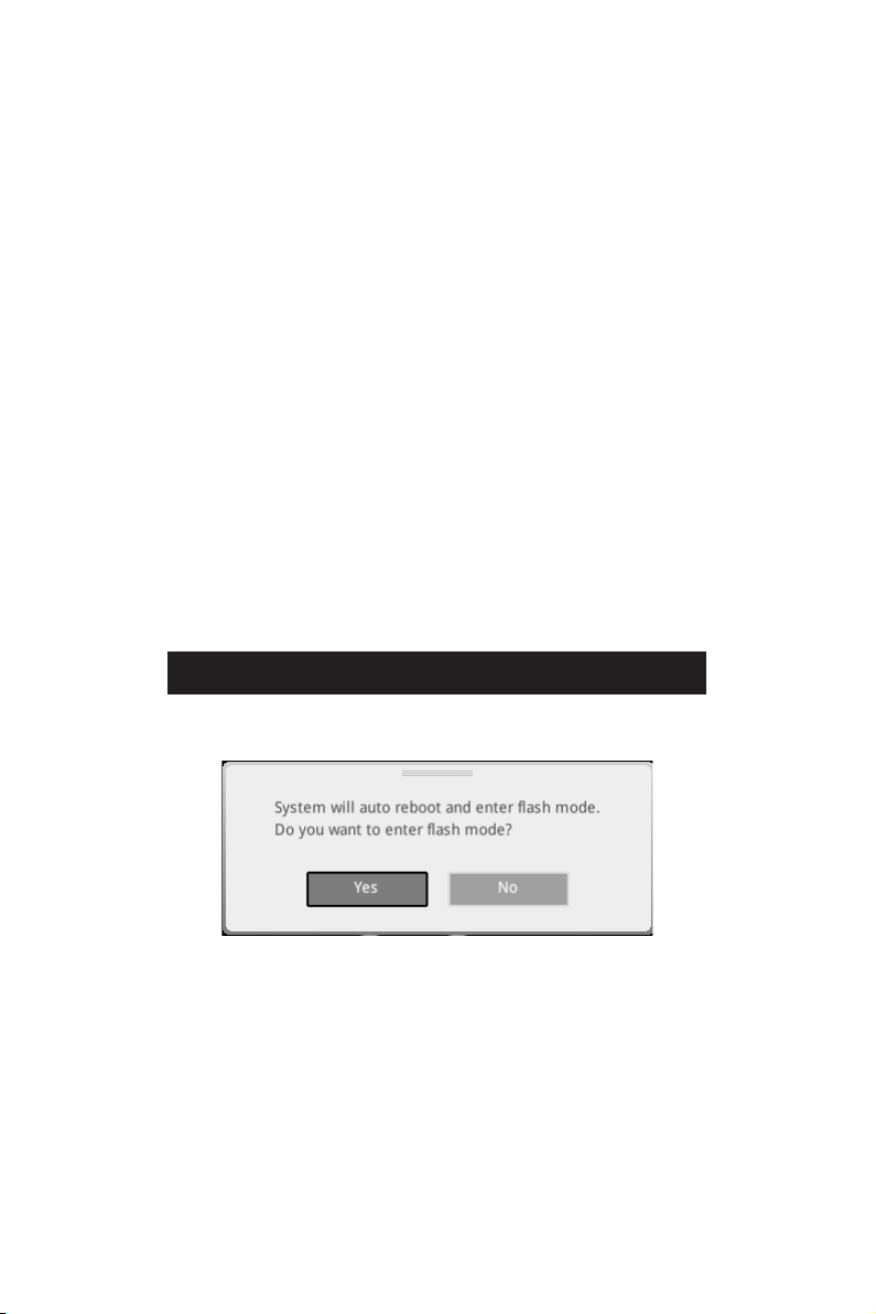
Updating BIOS:
1. Insert the USB flash drive that contains the update file into the USB port.
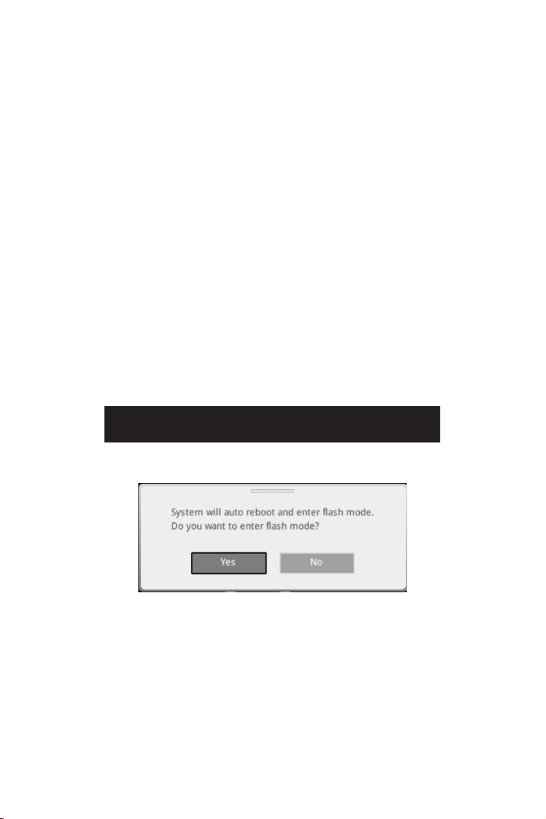
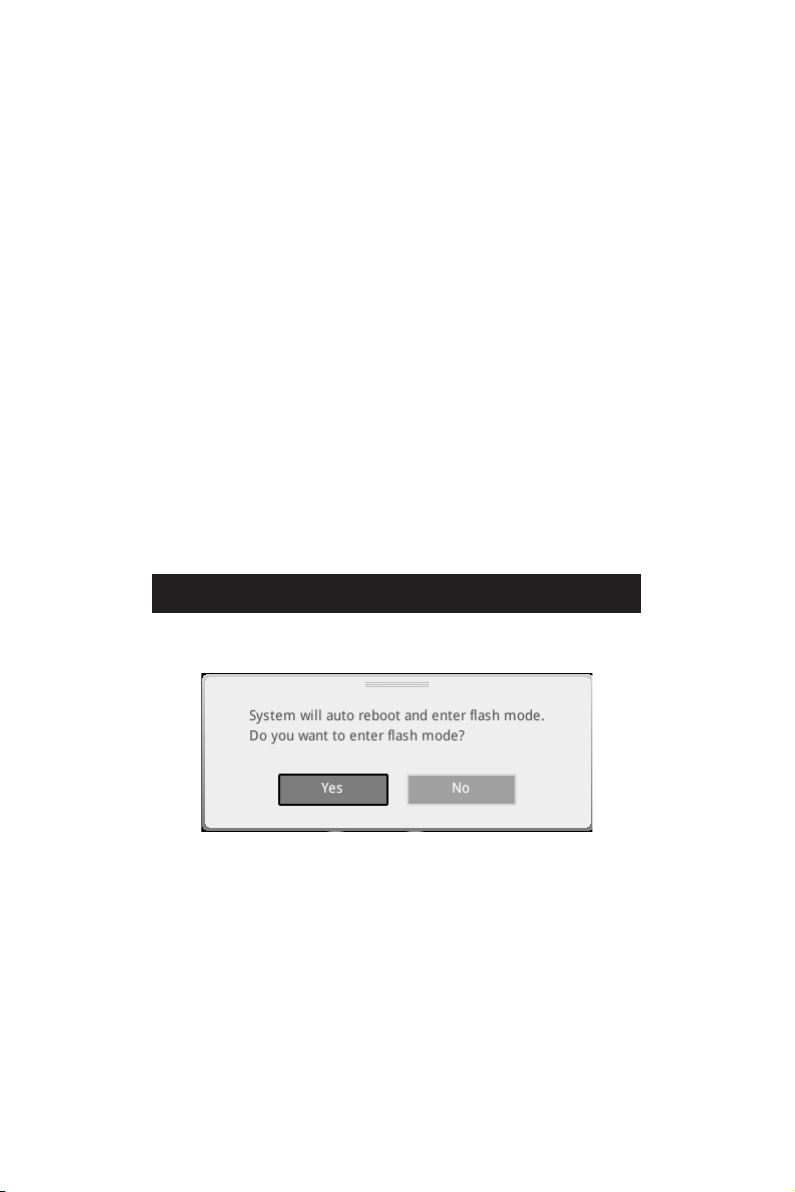
2. Please refer the following methods to enter flash mode.
Reboot and press Ctrl + F5 key during POST and click on Yes to reboot the
system.
Reboot and press DelM-FLASH button
and click on Yes to reboot the system.
3. Select a BIOS file to perform the BIOS update process.
4. When prompted click on Yes to start recovering BIOS.
5.
automatically.

32
UEFI BIOS
Updating BIOS with Flash BIOS Button
1. Please download the latest BIOS file that matches your motherboard model from
the MSI® website.
2. Rename the BIOS file to MSI.ROM
3. CPU_PWR1 and ATX_PWR1
4. Plug the USB flash drive that contains the MSI.ROM file into the Flash BIOS Port
on the rear I/O panel.
5. Press the Flash BIOS
6. The LED will be turned off when the process is completed.
33
UEFI BIOS
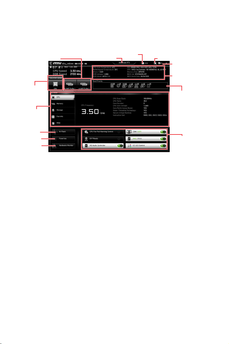
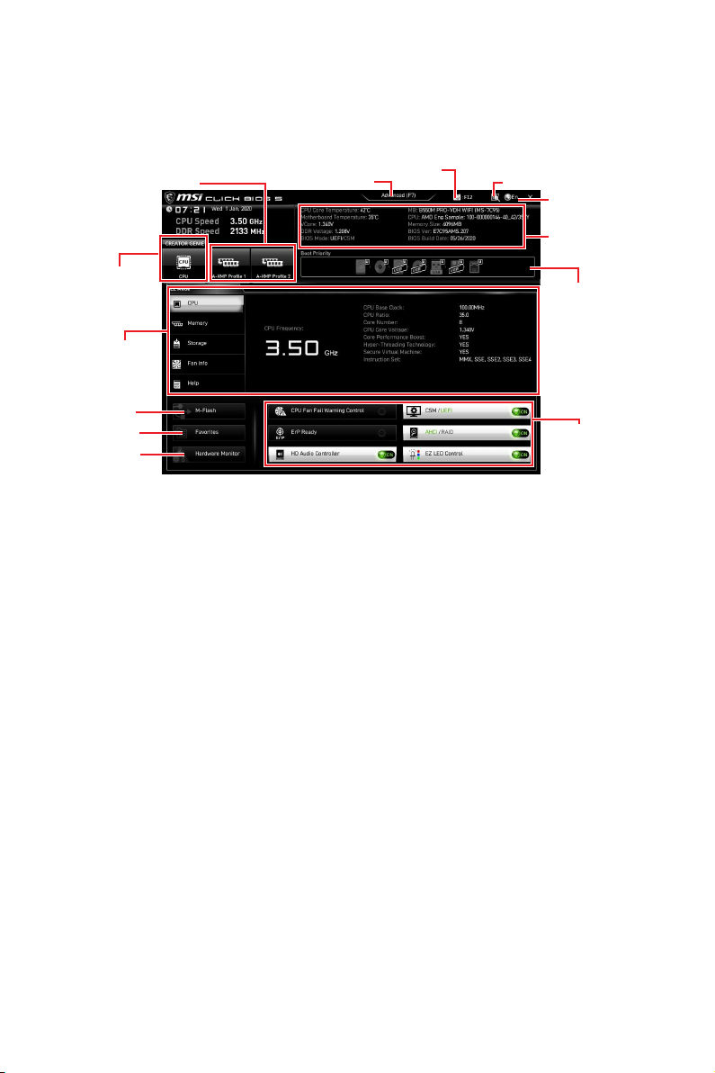
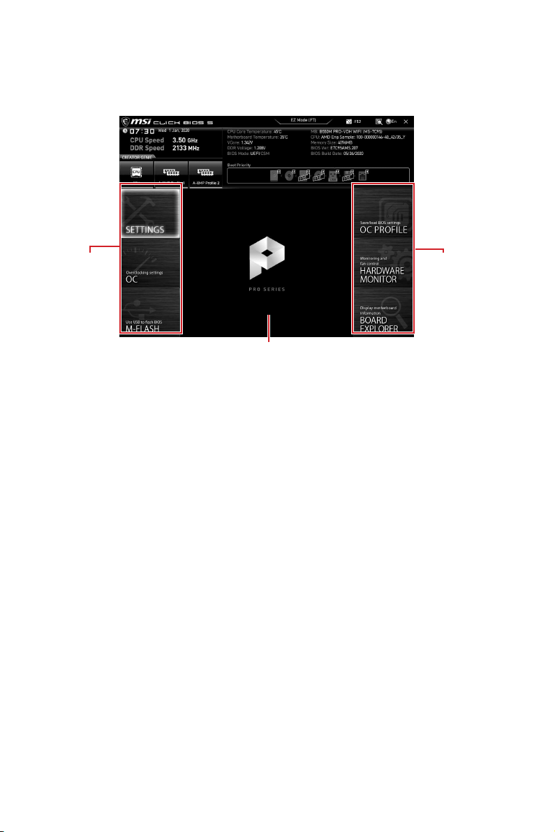
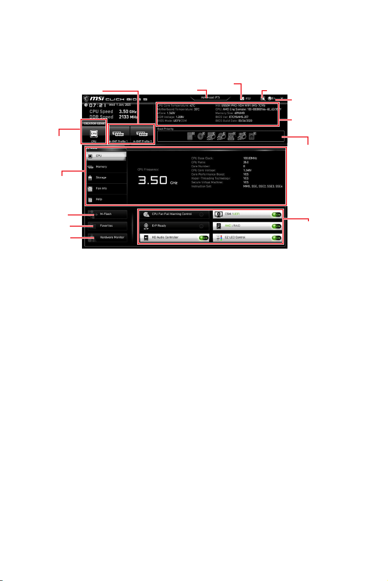
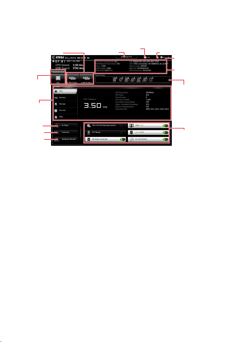
EZ Mode
Mode by pressing the Setup Mode switch or F7 function key.
A-XMP Profile
Information
System
information
Boot device
priority bar
Function
buttons
Language
GENIE
Search
Screenshot
Setup Mode switch
M-Flash
Hardware
Monitor
Favorites
CREATOR GENIE
are supporting this function.
Important
optimal performance and system stability after activating the CREATOR GENIE
function.
A-XMP Profile - allows you to select the A-XMP profile for memory to overclock.
function.
Setup Mode switch - press this tab or the F7 key to switch between Advanced mode
and EZ mode.
Screenshot - click on this tab or the F12 key to take a screenshot and save it to USB
Search - click on this tab or the Ctrl+F keys to enter the search page. It allows you
to search by BIOS item name. Move the mouse over a blank space and right click the
mouse to exit the search page.
Important
Language - allows you to select language of BIOS setup.
34
UEFI BIOS
System information
Boot device priority bar - you can move the device icons to change the boot priority.
The boot priority from high to low is left to right.
Component Information - click on the CPUMemoryStorageFan Info and Help
buttons to show the information of connected component.
Function buttons - enable or disable these functions by clicking on these buttons.
The function is enabled when the button shows ON .
Important
The function buttons will vary with the motherboard you purchased.
M-Flash - click on this button to enter the M-Flash menu that provides the way to
update BIOS with a USB flash drive.
Hardware Monitor - click on this button to enter the Hardware Monitor menu that
allows you to manually control the fan speed by percentage.
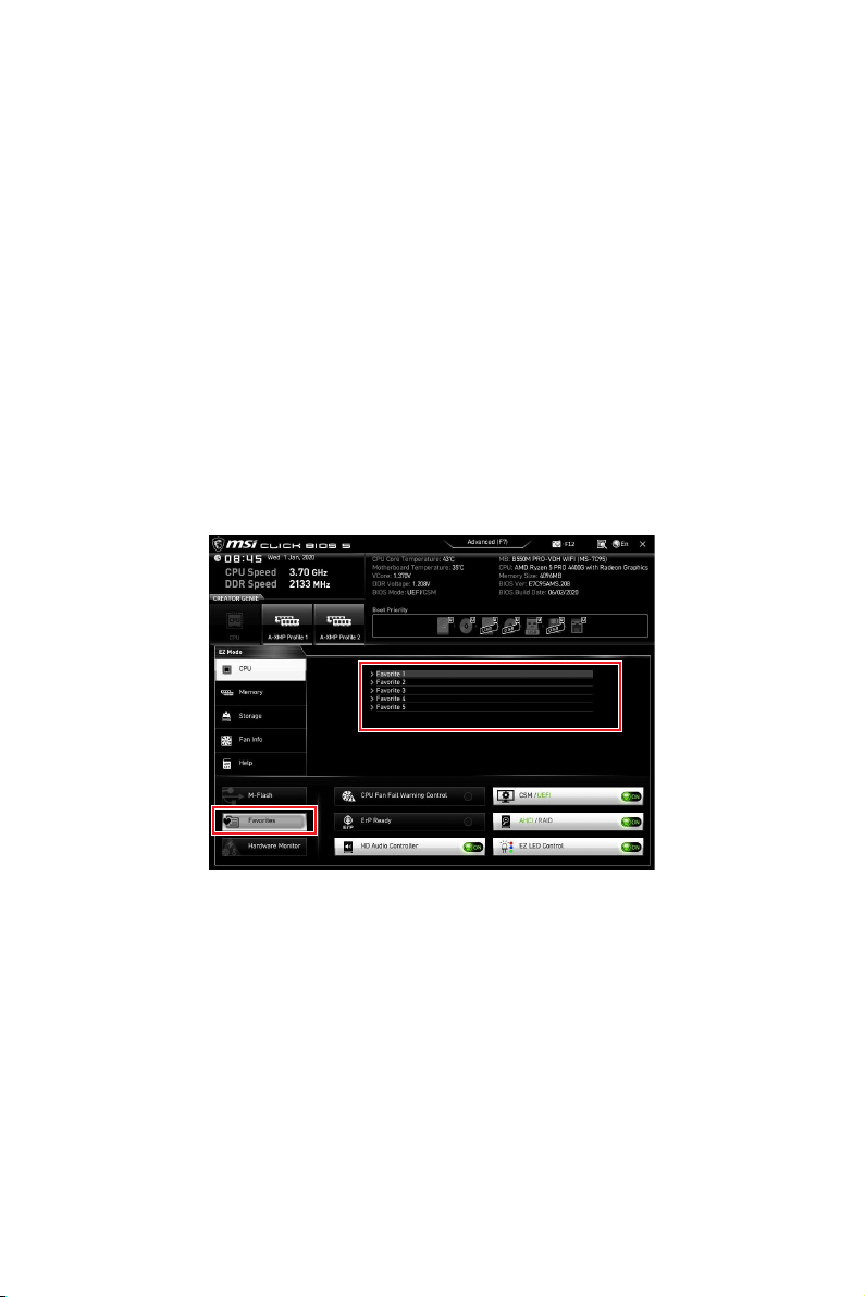
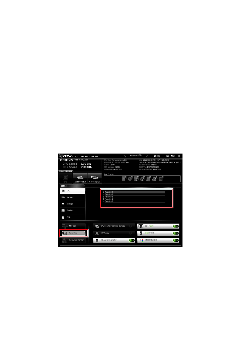
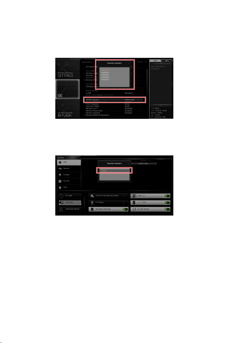
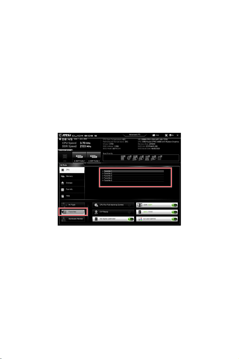
Favorites - click on this button or press the F3 key to show the Favorites window.
It provides 5 menus for you to create personal BIOS menu where you can save and
access favorite/ fre
quently-used BIOS setting items.

35
UEFI BIOS
To add a BIOS item to a favorite menu
1. Select a BIOS item not only on BIOS menu but also on search page.
2. Right-click or press F2 key.
3. OK.
To delete a BIOS item from favorite menu
1. Select a BIOS item on favorite menu.
2. Right-click or press F2 key.
3. Delete and click on OK.

36
UEFI BIOS
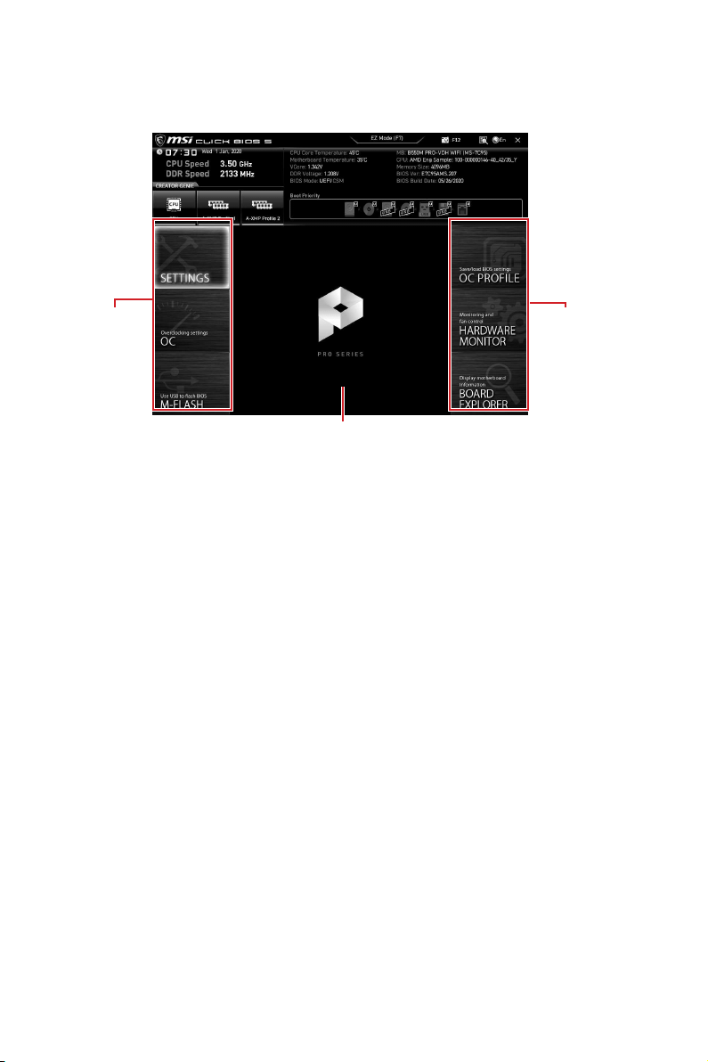
Advanced Mode
Press Setup Mode switch or F7 function key can switch between EZ Mode and
Advanced Mode in BIOS setup.
BIOS menu
selection
Menu display
BIOS menu
selection
BIOS menu selection - the following options are available:
SETTINGS - allows you to specify the parameters for chipset and boot devices.
OC - allows you to adjust the frequency and voltage. Increasing the frequency
may get better performance.
M-FLASH - provides the way to update BIOS with a USB flash drive.
OC PROFILE - allows you to manage overclocking profiles.
HARDWARE MONITOR - allows you to set the speeds of fans and monitor
voltages of system.
BOARD EXPLORER - provides the information of installed devices on this
motherboard.
Menu display - provides BIOS setting items and information to be configured.

37
UEFI BIOS
OC Menu
This menu allows you to configure the frequencies and voltages for overclocking.
cause system un-stability.
Important
or severely damage your hardware.
CREATOR GENIE
function for easy overclocking.
OC Explore Mode [Normal]
setup.
CPU Ratio [Auto]
changed if the processor supports this function.
Press Enter
power/ current. The system may become unstable or unbootable after changing the
A-XMP [Disabled]
Please enable A-XMP or select a profile of memory module for overclocking the
and motherboard support this function.
DRAM Frequency [Auto]
Sets the DRAM frequency. Please note the overclocking behavior is not guaranteed.
Adjusted DRAM Frequency
Shows the adjusted DRAM frequency. Read-only.
FCLK Frequency [Auto]
overclocking behavior is not guaranteed.
UCLK DIV1 Mode [Auto]

38
UEFI BIOS
Memory Try It ! [Disabled]
It can improve memory compatibility or performance by choosing optimized memory
preset. This item will be available when the installed processor supports this function.
Memory Failure Retry [Enabled]
Memory Failure Retry Count [2]
the memory will restore the last available settings. This item will display when the
Memory Failure Retry sets to Enabled.
Press Enter to enter the sub-menu. User can set the memory timing for each/ all
memory channel. The system may become unstable or unbootable after changing
DigitALL Power sub-menu
Press Enter
CPU Voltages control [Auto]
Auto
set these voltages automatically or you can set it manually.
DRAM Voltages control [Auto]
These options allows you to set the voltages related to memory. If set to Auto
will set these voltages automatically or you can set it manually.
CHIP Voltages control [Auto] (optional)
These options allows you to set the voltages related to chipset If set to Auto
set these voltages automatically or you can set it manually.
Memory Changed Detect [Enabled]*
Enables or disables the system to issue a warning message during boot when the
memory has been replaced.
[Enabled] The system will issue a warning message during boot and then you have
to load the default settings for new devices.
[Disabled] Disables this function and keeps the current BIOS settings.
Press Enter to enter the sub-menu. This sub-menu displays the information of
Read only.
MEMORY-Z sub-menu
Press Enter to enter the sub-menu. This sub-menu displays all the settings and
timings of installed memory. You can also access this information menu at any time by
pressing [F5].

1
........................................................................................... 2
........................................................................................................................ 3
.................................................................................................. 8
......................................................................................................... 9
............................................................................................. 9
.................................................................................. 9
.......................................................................................... 12
................................................................................................. 13
....................................................................................................... 14
................................................................................ 15
......................................................................... 15
............................................................................... 16
.................................................................. 18
................................................................... 18
.............................................................. 19
................................................. 20
.............................................................. 20
............................................................................... 21
........................................................................ 21
.................................. 22
...................................................................... 23
........................................................ 24
........................................................................ 24
............................................................................ 25
......................................................... 26
EZ Debug LED ....................................................................................................... 27
............................................................................ 27
............................................ 28
UEFI BIOS ............................................................................................................. 29
........................................................................................................... 30
................................................................................. 30
...................................................................................................... 31
........................................................................................ 31
................................................................................................................ 33
................................................................................................ 36
............................................................................................................ 37

2

3
CPU
DDR4 1866/ 2133/ 2400/ 2667/ 2800/
2933/ 3000/ 3066/ 3200 MHz
DDR4 2667/ 2800 /2933 /3000
/3066 /3200 /3466 /3600/ 3733 /3866 /4000 /4133 /4266
/4400+ MHz

4
M2_1
*
SATA 6Gb/s
M2_2
RAID
SATA
M.2 NVMe
USB
USB 3.2 Gen 1
USB 2.0 2 Type-A
USB 2.0
USB 3.2 Gen 1 5Gbps Type-A
LAN
LAN &
Bluetooth
®
Intel®

5
x1
EZ Debug LED x4
USB 2.0 Type-A x2

6
UEFI AMI BIOS
Norton™ Internet Security Solution
Mystic Light
User Scenario
Hardware Monitor
Live Update
Speed Up
Smart Tool
http://download.msi.
pdf

7
Audio Boost
Intel WiFi
LED
EZ DEBUG LED
DDR4 Boost
8
B550M PRO-VDH WIFI
1
1
1
1
1
1
1
1
9
Off
Off 10 Mbps
100 Mbps
1 Gbps
USB 3.2 Gen 1
USB 3.2 Gen 1
1 Gbps LAN
DisplayPort
VGA
USB 2.0
Type-A
10
1.
2.
3.

11
1.
2.
1
2

12
BAT1
JUSB3
LED_SW1
JRGB2
JRGB1
M2_1
JUSB1
JTPM1
JUSB2
JRAINBOW1
M2_2
SYS_FAN2
SYS_FAN1
JBAT1
PUMP_FAN1
JRAINBOW2
JAUD1
JUSB4
JFP1
JSMB1
SYS_FAN3
JFP2
ATX_PWR1
DIMMB1
DIMMB2
DIMMA1
DIMMA2

13
53.8 mm
14
DIMMA1 DIMMB1
DIMMA2 DIMMB2
DIMMA2
CPU CPU1.35V DIMM
DRAM Frequency
DIMMB2 DIMMB2
DIMMB1
DIMMA2
DIMMA2
DIMMA2
DIMMA1

15
MSI Gaming Series Graphics Card Bolster
T1
PCI_E1
PCI_E3
PCI_E2
SATA1
SATA3
SATA2
SATA4

16
M2_1 M2_2
1.
2.
1
1
2

17
30º30º
3
5
4
1.
M.2 SSD
2.
3.
3.
4.
5.
6.
6
6
18
1
2 10
9
1 2 Ground
3 4
5 Head Phone R 6
7 SENSE_SEND 8 No Pin
9 Head Phone L 10 Head Phone Detection
1
JFP2
+
+
-
-
Speaker
Buzzer
1 Speaker - 2 Buzzer +
3 Buzzer - 4 Speaker +
1
2 10
9
+
+
+-
--
-
+
Power LED
HDD LED Reset Switch
Reserved
Power Switch
JFP1
1 HDD LED + 2 Power LED +
3 HDD LED - 4 Power LED -
5 Reset Switch 6 Power Switch
7 Reset Switch 8 Power Switch
9 Reserved 10 No Pin

19
24
131
12
ATX_PWR1
1 +3.3V 13 +3.3V
2 +3.3V 14 -12V
3 Ground 15 Ground
4 +5V 16 PS-ON#
5 Ground 17 Ground
6 +5V 18 Ground
7 Ground 19 Ground
8 20 Res
9 5VSB 21 +5V
10 +12V 22 +5V
11 +12V 23 +5V
12 +3.3V 24 Ground
5
4 1
8
1 Ground 5 +12V
2 Ground 6 +12V
3 Ground 7 +12V
4 Ground 8 +12V

20
1
10 11
20
1 Power 11 USB2.0+
2 USB3_RX_DN 12 USB2.0-
3 USB3_RX_DP 13 Ground
4 Ground 14
5 15
6 16 Ground
7 Ground 17 USB3_RX_DP
8 USB2.0- 18 USB3_RX_DN
9 USB2.0+ 19 Power
10
Ground 20 No Pin
JUSB1

21
1
2 10
9
1 2
3 USB0- 4 USB1-
5 USB0+ 6 USB1+
7 Ground 8 Ground
9 No Pin 10
®
1
212
11
1 SPI Power 2
3
4
5 Reserved 6
7 Ground 8 SPI Reset
9 Reserved 10 No Pin
11 Reserved 12 Interrupt Request

22
BIOS > HARDWARE MONITOR
PWM/DC
SYS_FAN3
PUMP_FAN1
SYS_FAN1
SYS_FAN2
2A 24W
PUMP_FAN1 3A 36W
1A 12W
1
1 Ground 2 +12V
3 Sense 4
1
1 Ground 2
3 Sense 4

23
1.
JCI1
2.
3. BIOS > SETTINGS > Security > Chassis Intrusion Configuration
4. Chassis IntrusionEnabled
5. F10Enter
Yes
6.
1.
BIOS > SETTINGS > Security > Chassis Intrusion Configuration
2. Chassis IntrusionReset
3. F10Enter
Yes

24
1.
2. JBAT1
3. JBAT1
4.
1
2 10
9
1 2 SIN
3 SOUT 4 DTR
5 Ground 6 DSR
7 RTS 8
9 RI 10 No Pin
25
1
G
R
B
1
1 +12V 2 G
3 R 4 B
1
1
G
R
B

26
1
1
1
D
+5V
JRAINBOW
1
JRAINBOW1
1
JRAINBOW2
1 +5V 2 Data
3 No Pin 4 Ground

27
EZ Debug LED
CPU
DRAM
VGA
BOOT
LED_OFF
LED_ON

28
1.
2.
3. Restart
4. F11
5.
6. Press any key to boot from CD or DVD...
7.
1.
2.
3. Select to choose what happens with this disc
Run DVDSetup.exe
DVDSetup.exe
4.
5. Install
6.
7. OK
8.
1.
2. Utilities
3.
4. Install
5.
6. OK
7.

29
UEFI BIOS
UEFI BIOS
CPU Temperature:
Motherboard Temperature:
VCore:
DDR Voltage:
BIOS Mode:
UEFI/CSM
CPU Temperature:
Motherboard Temperature:
VCore:
DDR Voltage:
BIOS Mode: UEFI/
CSM

30
UEFI BIOS
HELP
Press DEL key to enter Setup Menu, F11 to enter Boot Menu
Delete
F1:
F2:
F3:
F4:
F5:
F6: O
F7:
F8:
F9:
F10: *
F12:
Ctrl+F:
31
UEFI BIOS
F6
1.
2.
Ctrl + F5 Yes
DeleteM-FLASH
Yes
3.
4. Yes
5.

32
UEFI BIOS
1.
2. MSI.ROM
3. CPU_PWR1ATX_PWR1
4. Flash BIOS
5. Flash BIOS
6.
33
UEFI BIOS
F7
Language
GENIE
M-Flash
CREATOR GENIE
CREATOR GENIE
CREATOR GENIE
F7
F12
Ctrl+F
34
UEFI BIOS
Help
ON
M-Flash - M-Flash
Hardware Monitor
F3
35
UEFI BIOS
1.
2. F2
3. OK
1.
2. F2
3. DeleteOK
36
UEFI BIOS
F7
SETTINGS -
OC -
M-FLASH -
OC PROFILE -
HARDWARE MONITOR -
BOARD EXPLORER -

37
UEFI BIOS
CREATOR GENIE
OC Explore Mode [Normal]
CPU Ratio [Auto]
CPUCPU
<Enter
A-XMP [Disabled]
A-XMP
DRAM Frequency [Auto]
Adjusted DRAM Frequency
FCLK Frequency [Auto]
UCLK DIV1 Mode [Auto]

38
UEFI BIOS
Memory Try It ! [Disabled]
Memory Failure Retry [Enabled]
Memory Failure Retry Count [2]
Memory Failure Retry
<Enter
DigitALL Power sub-menu
<Enter
CPU Voltages control [Auto]
Auto
DRAM Voltages control [Auto]
Auto
CHIP Voltages control [Auto] (optional)
Auto
Memory Changed Detect [Enabled]*
<Enter
MEMORY-Z sub-menu
<Enter

1
................................................................................................................ 2
......................................................................................................................... 3
.............................................................................................................. 8
........................................................................................................... 9
.......................................................................................... 9
................................................................................................. 9
............................................................................................................ 12
........................................................................................................ 13
............................................................................................................. 14
..................................................................................... 15
............................................................................... 15
..................................................................................... 16
................................................................................ 18
.................................................................................... 18
................................................................... 19
.......................................................... 20
.................................................................... 20
..................................................................................... 21
....................................................................................... 21
............................................. 22
........................................................................................... 23
............................................................... 24
.................................................................................... 24
................................................................................... 25
............................................... 26
....................................................................................................... 27
..................................................................................... 27
......................................................................... 28
UEFI BIOS ............................................................................................................. 29
.............................................................................................. 30
............................................................................................................... 30
............................................................................................................... 31
....................................................................................... 31
.................................................................................................................. 33
............................................................................................................ 36
.................................................................................................................. 37

2

3
CPU
DDR4 1866/ 2133/ 2400/ 2667/ 2800/ 2933/ 3000/ 3066/
3200 MHz
DDR4 2667/ 2800 /2933 /3000 /3066 /3200 /3466 /3600/
4400 MHZ
3733 MHZ
3866 MHZ
3466 MHZ
*
HDMI *

4
M2_1
RAID
USB
USB 3.2 Gen 1
USB 2.0 6
LAN
®

5
VGA

6
UEFI AMI BIOS
http://download.msi.

7
LED
8
B550M PRO-VDH WIFI
SATA 6G
1
1
1
1
1
1
1
1
9
USB 3.2 Gen 1
USB 3.2 Gen 1
1 Gbps LAN
VGA
USB 2.0
10
1.
2. Mute the rear output device, when a front headphone plugged in
3.

11
1.
2.
1
2

12
BAT1
JUSB3
LED_SW1
JRGB2
JRGB1
M2_1
JUSB1
JTPM1
JUSB2
JRAINBOW1
M2_2
SYS_FAN2
SYS_FAN1
JBAT1
PUMP_FAN1
JRAINBOW2
JAUD1
JUSB4
JFP1
JSMB1
SYS_FAN3
JFP2
ATX_PWR1
DIMMB1
DIMMB2
DIMMA1
DIMMA2
13
53.8 mm

14
DIMMA1 DIMMB1
DIMMA2 DIMMB2
DIMMA2
DRAM Frequency
DIMMB2 DIMMB2
DIMMB1
DIMMA2
DIMMA2
DIMMA2
DIMMA1
15
T1
PCI_E1
PCI_E3
PCI_E2
SATA1
SATA3
SATA2
SATA4

16
M2_1 M2_2
1.
2.
1
1
2
17
30º30º
M.2
3
5
4
1.
2.
3.
3.
4.
5.
6.
6
6

18
1
2 10
9
1 2 Ground
3 4
5 Head Phone R 6
7 SENSE_SEND 8 No Pin
9 Head Phone L 10 Head Phone Detection
1
JFP2
+
+
-
-
Speaker
Buzzer
1 Speaker - 2 Buzzer +
3 Buzzer - 4 Speaker +
1
2 10
9
+
+
+-
--
-
+
HDD LED
Reserved
JFP1
1 HDD LED + 2 Power LED +
3 HDD LED - 4 Power LED -
5 Reset Switch 6 Power Switch
7 Reset Switch 8 Power Switch
9 Reserved 10 No Pin

19
24
131
12
ATX_PWR1
1 +3.3V 13 +3.3V
2 +3.3V 14 -12V
3 Ground 15 Ground
4 +5V 16 PS-ON#
5 Ground 17 Ground
6 +5V 18 Ground
7 Ground 19 Ground
8 20 Res
9 5VSB 21 +5V
10 +12V 22 +5V
11 +12V 23 +5V
12 +3.3V 24 Ground
5
4 1
8
1 Ground 5 +12V
2 Ground 6 +12V
3 Ground 7 +12V
4 Ground 8 +12V

20
1
10 11
20
1 Power 11 USB2.0+
2 USB3_RX_DN 12 USB2.0-
3 USB3_RX_DP 13 Ground
4 Ground 14
5 15
6 16 Ground
7 Ground 17 USB3_RX_DP
8 USB2.0- 18 USB3_RX_DN
9 USB2.0+ 19 Power
10
Ground 20 No Pin
JUSB1

21
1
2 10
9
1 2
3 USB0- 4 USB1-
5 USB0+ 6 USB1+
7 Ground 8 Ground
9 No Pin 10
®
1
212
11
1 SPI Power 2
3
4
5 Reserved 6
7 Ground 8 SPI Reset
9 Reserved 10 No Pin
11 Reserved 12 Interrupt Request
22
PWMDC
SYS_FAN3
PUMP_FAN1
SYS_FAN1
SYS_FAN2
Auto mode 2A 24W
PUMP_FAN1 PWM mode 3A 36W
1A 12W
1
1 Ground 2 +12V
3 Sense 4
1
1 Ground 2
3 Sense 4
23
1.
JCI1
2.
3.
4.
5. EnterYes
6.
1.
BIOS > SETTINGS > Security > Chassis Intrusion Configuration
2.
3. F10Enter Yes

24
1.
2. JBAT1
3. JBAT1
4.
1
2 10
9
1 2 SIN
3 SOUT 4 DTR
5 Ground 6 DSR
7 RTS 8
9 RI 10 No Pin

25
1
G
R
B
JRGB
1
1 +12V 2 G
3 R 4 B
1
1
G
R
B

26
1
1
1
D
+5V
JRAINBOW
Rainbow RGB LED
1
JRAINBOW1
1
JRAINBOW2
1 +5V 2 Data
3 No Pin 4 Ground

27
CPU
DRAM
VGA
BOOT

28
Windows
®
1.
2.
3. Restart
4. F11
5.
6. Press any key to boot from CD or DVD...
7.
1.
2.
3. Select to choose what happens with this disc Run
DVDSetup.exe
DVDSetup.exe
4. Drivers/Software
5. Install
6.
7. OK
8.
1.
2. Utilities
3.
4. Install
5.
6. OK
7.

29
UEFI BIOS
UEFI BIOS
CPU Temperature:
Motherboard Temperature:
VCore:
DDR Voltage:
BIOS Mode:
UEFI/CSM
CPU Temperature:
Motherboard Temperature:
VCore:
DDR Voltage:
BIOS Mode: UEFI/
CSM

30
UEFI BIOS
Delete
F1
F2
F3
F4
F5
F6
F7
F8
F9
F10
F12
Ctrl+F
31
UEFI BIOS
F6
1.
2.
Ctrl + F5Yes
DelM-FLASH
Yes
3.
4. Yes
5.

32
UEFI BIOS
1.
2. MSI.ROM
3. CPU_PWR1ATX_PWR1
4.
5.
6.
33
UEFI BIOS
F7
F7
F12
Ctrl+F

34
UEFI BIOS
- CPUHelp
ON
-
F3

35
UEFI BIOS
1.
2. F2
3. OK
1.
2. F2
3. DeleteOK

36
UEFI BIOS
F7

37
UEFI BIOS
OC Explore Mode [Normal]
CPU Ratio [Auto]
Enter
A-XMP [Disabled]
DRAM Frequency [Auto]
Adjusted DRAM Frequency
FCLK Frequency [Auto]
UCLK DIV1 Mode [Auto]

38
UEFI BIOS
Memory Try It ! [Disabled]
Memory Failure Retry [Enabled]
Memory Failure Retry Count [2]
Memory Failure Retry
Enabled
Enter
DigitALL Power sub-menu
Enter
CPU Voltages control [Auto]
Auto
DRAM Voltages control [Auto]
Auto
CHIP Voltages control [Auto] (optional)
Auto
Memory Changed Detect [Enabled]*
Enter
MEMORY-Z sub-menu
Enter

1
................................................................................................................. 2
............................................................................................................. 3
................................................................................................................. 8
.................................................................................................................. 9
...................................................................................... 9
................................................................................................ 9
............................................................................................................... 12
............................................................................................................ 13
............................................................................................................ 14
..................................................................................... 15
.................................................................................. 15
...................................................................................... 16
.................................................................................... 18
........................................................................................... 18
...................................................................... 19
.......................................................... 20
....................................................................... 20
........................................................................................ 21
.......................................................................................... 21
................................... 22
............................................................................................... 23
............................................................ 24
.............................................................................................. 24
...................................................................................... 25
................................................................. 26
.............................................................................................. 27
............................................................................. 27
.................................................................. 28
UEFI BIOS ............................................................................................................. 29
.............................................................................................................. 30
...................................................................................................... 30
.............................................................................................................. 31
.............................................................................................................. 31
.................................................................................................................. 33
............................................................................................................... 36
.............................................................................................................. 37

2

3
AMD B550
128GB*
DDR4 1866/ 2133/ 2400/ 2667/ 2800/ 2933/ 3000/
3066/ 3200 MHz
DDR4 2667/ 2800 /2933 /3000 /3066 /3200 /3466
/3600/ 3733 /3866 /4000 /4133 /4266 /4400+ MHz
1
2
1 VGA
1
DisplayPort 4096x2160
1
HDMI

4
M2_1
M2_2
RAID
3 USB 3.2 Gen 1 5Gbps
2
6
Type-A 4
AMD
4 USB 3.2 Gen 1 5Gbps Type-A
Bluetooth
®
Intel®

5
1
4

6
I/O
Micro-ATX
9.6 x 9.6
1
256 Mb flash
UEFI AMI BIOS
Norton™ Internet Security Solution
Dragon Center
Mystic Light
User Scenario
Hardware Monitor
Live Update
Speed Up
Smart Tool
http://download.msi.com/

7
Intel WiFi
LED
EZ LED

8
B550M PRO-VDH WIFI
1
1
1
1
1
1
1
1

9
32
USB 3.2 Gen 1
USB 3.2 Gen 1
DisplayPort
VGA
USB 2.0
Type-A
10
1.
2.
3.
11
1.
2.
1
2
12
BAT1
JUSB3
LED_SW1
JRGB2
JRGB1
M2_1
JUSB1
JTPM1
JUSB2
JRAINBOW1
M2_2
SYS_FAN2
SYS_FAN1
JBAT1
PUMP_FAN1
JRAINBOW2
JAUD1
JUSB4
JFP1
JSMB1
SYS_FAN3
JFP2
ATX_PWR1
DIMMB1
DIMMB2
DIMMA1
DIMMA2

13
53.8 mm
®

14
DIMMA1 DIMMB1
DIMMA2 DIMMB2
DIMMA2
DRAM Frequency
DIMMB2 DIMMB2
DIMMB1
DIMMA2
DIMMA2
DIMMA2
DIMMA1
15
T1
PCI_E1
PCI_E3
PCI_E2
SATA1
SATA3
SATA2
SATA4

16
M2_1 M2_2
1.
2.
1
1
2
17
30º30º
3
5
4
1.
2.
3.
3.
4.
5.
6.
6
6

18
1
2 10
9
1 2 Ground
3 4
5 Head Phone R 6
7 SENSE_SEND 8 No Pin
9 Head Phone L 10 Head Phone Detection
1
JFP2
+
+
-
-
Speaker
Buzzer
1 Speaker - 2 Buzzer +
3 Buzzer - 4 Speaker +
1
2 10
9
+
+
+-
--
-
+
Power LED
HDD LED Reset Switch
Reserved
Power Switch
JFP1
1 HDD LED + 2 Power LED +
3 HDD LED - 4 Power LED -
5 Reset Switch 6 Power Switch
7 Reset Switch 8 Power Switch
9 Reserved 10 No Pin

19
24
131
12
ATX_PWR1
1 +3.3V 13 +3.3V
2 +3.3V 14 -12V
3 Ground 15 Ground
4 +5V 16 PS-ON#
5 Ground 17 Ground
6 +5V 18 Ground
7 Ground 19 Ground
8 20 Res
9 5VSB 21 +5V
10 +12V 22 +5V
11 +12V 23 +5V
12 +3.3V 24 Ground
5
4 1
8
1 Ground 5 +12V
2 Ground 6 +12V
3 Ground 7 +12V
4 Ground 8 +12V
20
1
10 11
20
1 Power 11 USB2.0+
2 USB3_RX_DN 12 USB2.0-
3 USB3_RX_DP 13 Ground
4 Ground 14
5 15
6 16 Ground
7 Ground 17 USB3_RX_DP
8 USB2.0- 18 USB3_RX_DN
9 USB2.0+ 19 Power
10
Ground 20 No Pin
JUSB1

21
1
2 10
9
1 2
3 USB0- 4 USB1-
5 USB0+ 6 USB1+
7 Ground 8 Ground
9 No Pin 10
®
1
212
11
1 SPI Power 2
3
4
5 Reserved 6
7 Ground 8 SPI Reset
9 Reserved 10 No Pin
11 Reserved 12 Interrupt Request

22
BIOS > HARDWARE MONITOR
PWMDC
SYS_FAN3
PUMP_FAN1
SYS_FAN1
SYS_FAN2
2A 24W
PUMP_FAN1 3A 36W
1A 12W
1
1 Ground 2 +12V
3 Sense 4
1
1 Ground 2
3 Sense 4

23
1.
JCI1
2.
3.
4. Chassis IntrusionEnabled
5. F10EnterYes
6.
1.
BIOS > SETTINGS > Security > Chassis Intrusion Configuration
2. Chassis IntrusionReset
3. F10 EnterYes
24
1.
2. JBAT1
3. JBAT1
4.
1
2 10
9
1 2 SIN
3 SOUT 4 DTR
5 Ground 6 DSR
7 RTS 8
9 RI 10 No Pin

25
1
G
R
B
1
1 +12V 2 G
3 R 4 B
1
1
G
R
B

26
1
1
1
D
+5V
JRAINBOW
1
JRAINBOW1
1
JRAINBOW2
1 +5V 2 Data
3 No Pin 4 Ground

27
CPU
DRAM
VGA
BOOT
LED_OFF
LED_ON

28
®
10
1.
2.
®
3.
4. F11
5.
®
6. Press any key to boot from CD or DVD...
7.
®
1.
®
2.
®
3.
4.
5.
6.
7.
8.
1.
2.
3.
4.
5.
6.
7.

29
UEFI BIOS
UEFI BIOS
There is no GOP (Graphics
Output protocol) support detected in this graphics card.
CPU Temperature:
Motherboard Temperature:
VCore:
DDR Voltage:
BIOS Mode:
UEFI/CSM
CPU Temperature:
Motherboard Temperature:
VCore:
DDR Voltage:
BIOS Mode: UEFI/
CSM

30
UEFI BIOS
HELP
Delete
F1:
F2:
F3:
F4:
F5:
F6:
F7:
F8:
F9:
F10: *
F12:
Ctrl+F:
31
UEFI BIOS
F6
1.
2.
Ctrl + F5
DelM-FLASH
3.
4. Yes
5.

32
UEFI BIOS
1.
2. MSI.ROMMSI.ROM
3. CPU_PWR1ATX_PWR1
4.
5. Flash BIOS
6.
33
UEFI BIOS
F7
GENIE
M-Flash
CREATOR GENIE CREATOR GENIE
CREATOR GENIE
F7
F12
Ctrl+F
34
UEFI BIOS
CPUMemoryStorageFan InfoHelp
ON
M-FlashM-Flash
F3

35
UEFI BIOS
1.
2. F2
3. OK
1.
2. F2
3. DeleteOK
36
UEFI BIOS
F7
SETTINGS ()
OC
M-FLASH
OC PROFILE
HARDWARE MONITOR ()
BOARD EXPLORER

37
UEFI BIOS
CREATOR GENIE
OC Explore Mode [Normal]
CPU Ratio [Auto]
Enter
A-XMP [Disabled]
DRAM Frequency [Auto]
Adjusted DRAM Frequency
FCLK Frequency [Auto]
UCLK DIV1 Mode [Auto]

38
UEFI BIOS
Memory Try It ! [Disabled]
Memory Failure Retry [Enabled]
Memory Failure Retry Count [2]
Memory Failure Retry Enabled
Enter
DigitALL Power sub-menu
Enter
CPU Voltages control [Auto]
DRAM Voltages control [Auto]
CHIP Voltages control [Auto] (optional)
Memory Changed Detect [Enabled]*
Enter
MEMORY-Z sub-menu
Enter

1
................................................................................................................. 2
........................................................................................................................ 3
................................................................................................................. 8
.......................................................................................................... 9
............................................................................................. 9
................................................................................................ 9
............................................................................................................... 12
............................................................................................................ 13
............................................................................................................ 14
..................................................................................... 15
.................................................................................. 15
...................................................................................... 16
.................................................................................... 18
........................................................................................... 18
...................................................................... 19
.......................................................... 20
....................................................................... 20
........................................................................................ 21
.......................................................................................... 21
............................................. 22
........................................................................................ 23
.................................................................... 24
........................................................................................... 24
...................................................................................... 25
.................................................................... 26
................................................................................................... 27
................................................................................. 27
................................................................... 28
UEFI BIOS ............................................................................................................. 29
.............................................................................................................. 30
...................................................................................................... 30
.............................................................................................................. 31
.............................................................................................................. 31
.................................................................................................................. 33
............................................................................................................... 36
................................................................................................................. 37

2

3
CPU
4 128GB*
3066/ 3200 MHz
/3600/ 3733 /3866 /4000 /4133 /4266 /4400+ MHz
*
1 DisplayPort 4096x2160
1
HDMI
16 GB

4
AMD B550
M2_1
M2_2 B550
RAID
USB
AMD B550
3 USB 3.2 Gen 1 5Gbps
USB 3.2 Gen 1 5Gbps 2
6
AMD
4
7.1-
LAN
®
Intel®

5
1
3 4-pin
1
2
1
1
2
2 3-pin
1
1

6
/
UEFI AMI BIOS
Live Update
http://
download.msi.com/manual/mb/

7
Intel WiFi
DDR4

8
B550M PRO-VDH WIFI
SATA 6G 1
1
1
1
1
1
1
1

9
USB 3.2 Gen 1
USB 3.2 Gen 1
1 Gbps LAN
VGA
USB 2.0
Type-A
10
1.
2. Mute the rear output device, when a front headphone plugged in
3.

11
1.
2.
1
2

12
BAT1
JUSB3
LED_SW1
JRGB2
JRGB1
M2_1
JUSB1
JTPM1
JUSB2
JRAINBOW1
M2_2
SYS_FAN2
SYS_FAN1
JBAT1
PUMP_FAN1
JRAINBOW2
JAUD1
JUSB4
JFP1
JSMB1
SYS_FAN3
JFP2
ATX_PWR1
DIMMB1
DIMMB2
DIMMA1
DIMMA2

13
®

14
DIMMA1 DIMMB1
DIMMA2 DIMMB2
DIMMA2
DRAM Frequency
DIMMB2 DIMMB2
DIMMB1
DIMMA2
DIMMA2
DIMMA2
DIMMA1

15
T1
PCI_E1
PCI_E3
PCI_E2
SATA1
SATA3
SATA2
SATA4
16
M2_1 M2_2
1.
2.
1
1
2
http://v.youku.com/v_show/id_
XNzUyMTY3MjY4.html

17
30º30º
3
5
4
1.
2.
3.
3.
4.
5.
6.
6
6

18
1
2 10
9
1 2 Ground
3 4
5 Head Phone R 6
7 SENSE_SEND 8 No Pin
9 Head Phone L 10 Head Phone Detection
1
JFP2
+
+
-
-
Speaker
Buzzer
1 Speaker - 2 Buzzer +
3 Buzzer - 4 Speaker +
1
2 10
9
+
+
+-
--
-
+
Power LED
HDD LED Reset Switch
Reserved
Power Switch
JFP1
1 HDD LED + 2 Power LED +
3 HDD LED - 4 Power LED -
5 Reset Switch 6 Power Switch
7 Reset Switch 8 Power Switch
9 Reserved 10 No Pin

19
24
131
12
ATX_PWR1
1 +3.3V 13 +3.3V
2 +3.3V 14 -12V
3 Ground 15 Ground
4 +5V 16 PS-ON#
5 Ground 17 Ground
6 +5V 18 Ground
7 Ground 19 Ground
8 20 Res
9 5VSB 21 +5V
10 +12V 22 +5V
11 +12V 23 +5V
12 +3.3V 24 Ground
5
4 1
8
1 Ground 5 +12V
2 Ground 6 +12V
3 Ground 7 +12V
4 Ground 8 +12V
20
1
10 11
20
1 Power 11 USB2.0+
2 USB3_RX_DN 12 USB2.0-
3 USB3_RX_DP 13 Ground
4 Ground 14
5 15
6 16 Ground
7 Ground 17 USB3_RX_DP
8 USB2.0- 18 USB3_RX_DN
9 USB2.0+ 19 Power
10
Ground 20 No Pin
JUSB1
21
1
2 10
9
1 2
3 USB0- 4 USB1-
5 USB0+ 6 USB1+
7 Ground 8 Ground
9 No Pin 10
®
DRAGON
1
212
11
1 SPI Power 2
3
4
5 Reserved 6
7 Ground 8 SPI Reset
9 Reserved 10 No Pin
11 Reserved 12 Interrupt Request

22
BIOS > HARDWARE MONITOR
PWMDC
SYS_FAN3
PUMP_FAN1
SYS_FAN1
SYS_FAN2
2A 24W
PUMP_FAN1 3A 36W
1A 12W
1
1 Ground 2 +12V
3 Sense 4
1
1 Ground 2
3 Sense 4
23
1.
JCI1
2.
3. BIOS > SETTINGS > Security > Chassis Intrusion Configuration
4. Chassis IntrusionEnabled
5. F10EnterYes
6.
1.
BIOS > SETTINGS > Security > Chassis Intrusion Configuration
2. Chassis IntrusionReset
3. F10 EnterYes
24
1.
2. JBAT1
3. JBAT1
4.
1
2 10
9
1 2 SIN
3 SOUT 4 DTR
5 Ground 6 DSR
7 RTS 8
9 RI 10 No Pin
25
1
G
R
B
1
1 +12V 2 G
3 R 4 B
1
1
G
R
B
26
1
1
1
D
+5V
JRAINBOW
1
JRAINBOW1
1
JRAINBOW2
1 +5V 2 Data
3 No Pin 4 Ground

27
CPU
DRAM
VGA
BOOT
LED_OFF
LED_ON

28
®
10
1.
2.
®
3. Restart
4. F11
5.
®
6. Press any key to boot from CD or DVD...
7.
®
1.
®
2.
®
3. Select to choose what happens with this disc Run
DVDSetup.exe
DVDSetup.exe
4. Drivers/Software
5. Install
6.
7. OK
8.
1.
2. Utilities
3.
4. Install
5.
6. OK
7.

29
UEFI BIOS
UEFI BIOS
There is no GOP (Graphics
Output protocol) support detected in this graphics card
CPU Temperature:
Motherboard Temperature:
VCore:
DDR Voltage:
BIOS Mode:
UEFI/CSM
CPU Temperature:
Motherboard Temperature:
VCore:
DDR Voltage:
BIOS Mode: UEFI/
CSM

30
UEFI BIOS
Press DEL key to enter Setup Menu, F11 to enter Boot
MenuDelete
F1
F2
F3
F4
F5
F6
F7
F8
F9
F10*
F12
Ctrl+F
31
UEFI BIOS
F6
1.
2.
Ctrl + F5 Yes
DelM-FLASH Yes
3.
4. Yes
5.

32
UEFI BIOS
1.
2. MSI.ROM
3. CPU_PWR1ATX_PWR1
4.
5.
6.

33
UEFI BIOS
F7
M-Flash
F7
F12
Ctrl+F
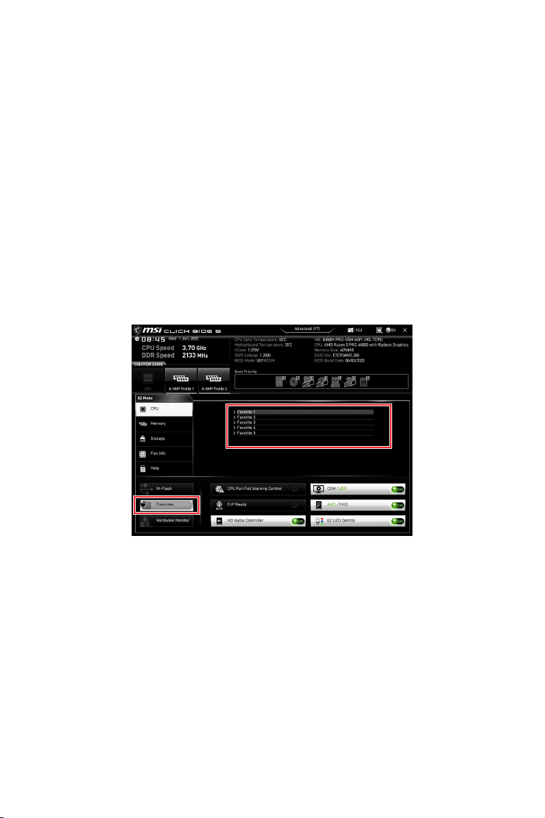
34
UEFI BIOS
CPUMemoryStorageFan InfoHelp
ON
M-FlashM-Flash
Hardware Monitor
F3

35
UEFI BIOS
1.
2. F2
3. OK
1.
2. F2
3. DeleteOK

36
UEFI BIOS
F7
SETTINGS
OC
M-FLASH
OC PROFILE
HARDWARE MONITOR
BOARD EXPLORER

37
UEFI BIOS
OC Explore Mode [Normal]
CPU Ratio [Auto]
Enter
A-XMP [Disabled]
DRAM Frequency [Auto]
Adjusted DRAM Frequency
FCLK Frequency [Auto]
UCLK DIV1 Mode [Auto]

38
UEFI BIOS
Memory Try It ! [Disabled]
Memory Failure Retry [Enabled]
Memory Failure Retry Count [2]
Memory Failure RetryEnabled
Enter
DigitALL Power sub-menu
Enter
CPU Voltages control [Auto]
Auto
DRAM Voltages control [Auto]
Auto
Auto
Memory Changed Detect [Enabled]*
Enter
MEMORY-Z sub-menu
Enter
i
Regulatory Notices
Regulatory Notices
FCC Compliance Statement
Note: This equipment has been tested and found to
designed to provide reasonable protection against
harmful interference in a residential installation. This
is no guarantee that interference will not occur in a
particular installation. If this equipment does cause
which can be determined by turning the equipment
interference by one or more of the following measures:
· Reorient or relocate the receiving antenna.
· Increase the separation between the equipment
and receiver.
·
different from that to which the receiver is
connected.
·
technician for help.
approved by the party responsible for compliance could
Operation is subject to the following two conditions:
undesired operation.
CE Conformity
with one or more of the following EU
Directives as may be applicable:
RED 2014/53/EU; Low Voltage Directive 2014/35/EU;
applicable European Harmonized Standards.
MSI-NL Eindhoven 5706 5692 ER Son.
VCCI-B
C-Tick Compliance
Battery Information
European Union:
accumulators should not be disposed of as
unsorted household waste. Please use the
or treat them in compliance with the local
regulations.
Taiwan:
waste batteries should be collected
separately for recycling or special
disposal.
The button cell battery may contain
perchlorate material and requires special
handling when recycled or disposed of in
For further information please visit:
http://www.dtsc.ca.gov/hazardouswaste/perchlorate/
incorrectly replaced.
Replace only with the same or equivalent type
recommended by the manufacturer.
Chemical Substances Information
No. 1907/2006 of the European Parliament and the
substances in products at:
http://www.msi.com/html/popup/csr/evmtprtt_pcm.
html
Environmental Policy
· The product has been designed to
enable proper reuse of parts and
recycling and should not be thrown
away at its end of life.
· Users should contact the local
authorized point of collection for recycling and
disposing of their end-of-life products.
· Visit the MSI website and locate a nearby distributor
for further recycling information.
·
WEEE (Waste Electrical and
Electronic Equipment) Statement
ENGLISH
To protect the global environment and as
you that...
on Waste Electrical and Electronic

ii
Regulatory Notices
covered electronic equipment will be obligated to take
back such products at the end of their useful life. MSI
will comply with the product take back requirements
at the end of life of MSI-branded products that are sold
into the EU. You can return these products to local
collection points.
DEUTSCH
Hinweis von MSI zur Erhaltung und Schutz unserer
Umwelt
Gemäß der Richtlinie 2002/96/EG über Elektro- und
Elektronik-Altgeräte dürfen Elektro- und Elektronik-
Altgeräte nicht mehr als kommunale Abfälle entsorgt
werden. MSI hat europaweit verschiedene Sammel-
am Ende seines Lebenszyklus zurückzunehmen.
Bitte entsorgen Sie dieses Produkt zum gegebenen
Zeitpunkt ausschliesslich an einer lokalen
Altgerätesammelstelle in Ihrer Nähe.
FRANÇAIS
de vie. MSI prendra en compte cette exigence relative
au retour des produits en fin de vie au sein de la
de collecte.
ESPAÑOL
MSI como empresa comprometida con la protección
a hacerse cargo de dichos productos al termino de
la Unión Europea al final de su periodo de vida. Usted
debe depositar estos productos en el punto limpio
establecido por el ayuntamiento de su localidad o
entregar a una empresa autorizada para la recogida de
estos residuos.
NEDERLANDS
herinneren dat….
tot Vervuiling van Electrische en Electronische
zal gaan kunnen niet meer beschouwd worden als
vervuiling. Fabrikanten van dit soort producten worden
verplicht om producten retour te nemen aan het
eind van hun levenscyclus. MSI zal overeenkomstig
de richtlijn handelen voor de producten die de
merknaam MSI dragen en verkocht zijn in de EU. Deze
goederen kunnen geretourneerd worden op lokale
inzamelingspunten.
SRPSKI
vas podesti da…
vratiti na lokalnim mestima za prikupljanje.
POLSKI
odpadów produktów elektrycznych i elektronicznych
wyznaczonych punktach zbiorczych.
TÜRKÇE

iii
Regulatory Notices
MAGYAR
ITALIANO
prodotti appartenenti alla categoria dei Materiali
Elettrici ed Elettronici non possono più essere eliminati
come rifiuti municipali: i produttori di detti materiali
saranno obbligati a ritirare ogni prodotto alla fine
ritirando tutti i prodotti marchiati MSI che sono stati
loro ciclo di vita. È possibile portare i prodotti nel più
vicino punto di raccolta
http://www.msi.com/html/popup/csr/cemm_jp.html
http://tw.msi.com/html/popup/csr_tw/cemm_jp.html
India RoHS
polybrominated biphenyls or polybrominated diphenyl
set in Schedule 2 of the Rule.
Wireless Radio Use
This device is restricted to indoor use when operating
Products with radio functionality (EMF)
This product incorporates a radio transmitting
and receiving device. For computers in normal
radio frequency exposure levels comply with EU
requirements. Products designed to be operated
comply with applicable EU requirements in typical
operating positions. Products can be operated without
maintaining a separation distance unless otherwise
indicated in instructions specific to the product.
Restrictions for products with radio functionality
5.15–5.35 GHz frequency band is restricted
for indoor use only in all European Union
Using this WLAN application outdoors might lead to
interference issues with existing radio services.
Radio frequency bands and maximum power levels
iv
Regulatory Notices
+6
Copyright
The MSI logo used is a registered trademark of
mentioned may be trademarks of their respective
owners. No warranty as to accuracy or completeness is
expressed or implied. MSI reserves the right to make
changes to this document without prior notice.
Revision History
Technical Support
If a problem arises with your system and no solution
contact your place of purchase or local distributor.
for further guidance.
·
http://www.msi.com
· Register your product at: http://register.msi.com