XM-GS4
4-569-998-12(1)
Stereo Power Amplifier
For customers in the United States:
The warranty for this product is included in this manual
(page 12).
Owner’s Record
The model and serial numbers are located on the bottom of the unit.
Record the serial number in the space provided below.
Refer to these numbers whenever you call upon your Sony dealer
regarding this product.
Model No. XM-GS4
Serial No.
Operating Instructions
GB
2GB
Made in Thailand
Notice for customers: the following
information is only applicable to equipment
sold in countries applying EU Directives
Manufacturer: Sony Corporation, 1-7-1 Konan
Minato-ku Tokyo, 108-0075 Japan
For EU product compliance: Sony Deutschland
GmbH,
Hedelfinger Strasse 61, 70327 Stuttgart,
Germany
Disposal of waste batteries and
electrical and electronic
equipm
ent (applicable in the
European Union and other
European countries with separate
collection systems)
This symbol on the product, the battery or on the
packaging indicates that the product and the
battery shall not be treated as household waste.
On certain batteries this symbol might be used in
combina
tion with a chemical symbol. The chemical
symbols for mercury (Hg) or lead (Pb) are added if
the battery contains more than 0.0005% mercury or
0.004% lead.
By ensuring these products and batteries are
dispos
ed of correctly, you will help prevent
potentially negative consequences for the
environment and human health which could
otherwise be caused by inappropriate waste
handling. The recycling of the materials will help to
conserve natural resources.
In case of products that for safety, performance or
da
ta integ
rity reasons require a permanent
connection with an incorporated battery, this
battery should be replaced by qualified service staff
only.
To ensure that the battery and the electrical and
electro
nic equipment will be treated properly, hand
over these products at end-of-life to the applicable
collection point for the recycling of electrical and
electronic equipment.
For all other batteries, please view the section on
ho
w to re
move the battery from the product safely.
Hand the battery over to the applicable collection
point for the recycling of waste batteries.
For more detailed information about recycling of
this pr
oduct or battery, please contact your local
Civic Office, your household waste disposal service
or the shop where you purchased the product or
battery.
This symbol is intended to alert the user to
the presence of a hot surface. The symbol
applies to Europe models only.
If you have any questions or problems concerning
your unit that
are not covered in this manual,
please consult your nearest Sony dealer.
For safety, be sure to install this unit either inside
the tr
unk (boot) or under a seat. For details, see
“Installation and Connections” (page 5).

3GB
Features
Maximum power output of 150 W per channel (at
4 Ω).
This unit can be used as a bridging amplifier with
a maximum outp
ut of 350 W.
Built-in LP (low-pass) filter, HP (high-pass) filter,
subso
nic filter and Low boost circuit.
Protection circuit and indicator provided.
Direct connection can be made with the speaker
output of y
our car audio unit if it is not equipped
with the line output (High level input connection).
Hi-level Sensing Power On feature allows this unit
to be a
ctivated without the need for REMOTE
connection.
Pulse power supply* for stable and regulated
output p
ower.
* Pulse power supply
This unit has a built-in power regulator which
conver
ts the power supplied by the 12 V DC car
battery into high speed pulses using a semiconductor
switch. These pulses are stepped up by the built-in
pulse transformer and separated into both positive
and negative power supplies before being converted
into direct current again. This is to regulate
fluctuating voltage from the car battery. This light-
weight power supply system provides a highly
efficient power supply with a low impedance output.
Table of Contents
Features . . . . . . . . . . . . . . . . . . . . . . . . . . . . . . . . . . . 3
Operation
Location and Function of Controls . . . . . . . . . . . . . . 4
Installation and Connections
Parts for Installation and Connections. . . . . . . . . . . 5
Installation . . . . . . . . . . . . . . . . . . . . . . . . . . . . . . . . . 5
Connections . . . . . . . . . . . . . . . . . . . . . . . . . . . . . . . . 5
Power Connections . . . . . . . . . . . . . . . . . . . . . . . 5
Input Connections . . . . . . . . . . . . . . . . . . . . . . . . 6
Speaker Connections . . . . . . . . . . . . . . . . . . . . . 7
Additional Information
Precautions . . . . . . . . . . . . . . . . . . . . . . . . . . . . . . . . 9
Maintenance . . . . . . . . . . . . . . . . . . . . . . . . . . . . . . . 9
Fuse Replacement. . . . . . . . . . . . . . . . . . . . . . . . 9
Specifications. . . . . . . . . . . . . . . . . . . . . . . . . . . . . . 10
Troubleshooting . . . . . . . . . . . . . . . . . . . . . . . . . . . 11
For customers in the United States:
Important notice
The warranty for this product is included in this
manual (page 12). Keep this manual for future
use.
4GB
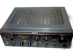
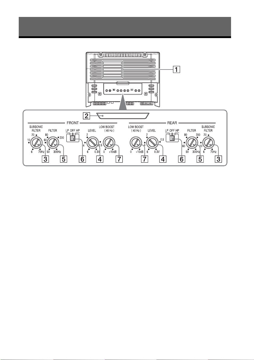
Location and Function of Controls
Ventilation outlet
Dissipates heat.
Depending on the temperature of the unit, the
fan operat
es in one of three status (stopped,
low-speed, high-speed).
Illumination indicator
Lights
up in white during operation.
If the protection circuit activates, the
illuminati
on indicator changes from white to
red.
For details, see “Troubleshooting” (page 11).
SU
BSONIC FILTER adjustment control
Adju
sts the cut-off frequency (6 – 70 Hz) for the
subsoni
c filter.
LEVEL adjustment control
Adjus
ts the input level.
Turn it in the clockwise direction when the
output lev
el of the car audio unit seems low.
Cut-off frequency adjustment control
Adjust
s the cut-off frequency (50 – 300 Hz) for
the low
-pass or high-pass filter.
FILTER selector switch
Sele
cts the low-pass filter (LP) or the high-pass
filter (
HP).
L
OW BOOST level control
Boosts
the frequencies around 40 Hz to a
maximum of 10
dB.
Operation
5GB
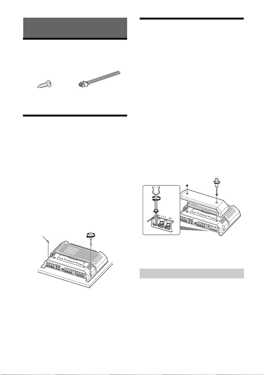
Parts for Installation and
Connections
This parts list does not include all the package
contents.
Installation
Mount the unit either inside the trunk (boot) or
under a seat.
Choose the mounting location carefully so the
unit will no
t interfere with the normal movements
of the driver and it will not be exposed to direct
sunlight or hot air from the heater.
Do no
t install the unit under the floor carpet,
where t
he heat dissipation from the unit will be
considerably impaired.
Mounting the unit
First, place the unit where you plan to install it, and
mark the positions of the 4 screw holes on the
mounting board (not supplied). Then drill a 3 mm
(
1
/8 in) pilot hole at each mark and mount the unit
onto the board with the supplied mounting screws.
The mounting screws are all 14 mm (
9
/16 in) long, so
make sure that the mounting board is thicker than
14 mm (
9
/16 in).
Connections
Before making any connections, disconnect the
ground (earth) terminal of the car battery to avoid
short circuits.
Be sure to use speakers with an adequate power
rating
. If you use small capacity speakers, they
may be damaged.
This is a Phase-Inverted Amplifier.
Do not connect the t
erm
inal of the speaker
system to the car chassis, and do not connect the
terminal of the right speaker with that of the
left speaker.
Install the input and output cords away from the
power
supply wire. Running them close together
may generate interference noise.
This unit is a high powered amplifier. Therefore, it
may n
ot perform to its full potential if used with
the speaker cords supplied with the car.
If your car is equipped with a computer system for
naviga
tion or some other purpose, do not remove
the ground (earth) wire from the car battery. If you
disconnect the wire, the computer memory may
be erased. To avoid short circuits when making
connections, disconnect the +12 V power supply
wire un
til all the other wires have been
connected.
Making the terminal connections
Note
When you tighten the screw, be careful not to apply too
much tor
que as doing so may damage the screw (the
torque value should be less than 1 N•m).
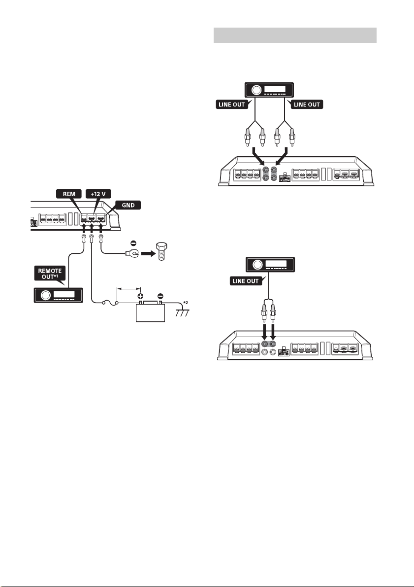
Connect the +12 V power supply wire only after all
the other wires have been connected.
Be sure to connect the ground (earth) wire of the
unit secur
ely to a metal point of the car. A loose
connection may cause a malfunction of the
amplifier.
B
e sure to connect the remote control wire of the
car aud
io unit to the remote input (REM) terminal.
When using a car audio unit without a remote
output
for the amplifier, connect the remote input
(REM) terminal to the accessory power supply.
Installation and Connections
ø4 × 14 mm
(
3
/16 ×
9
/16 in)
× 4
Power Connections
6GB
Use a power supply wire with a fuse (60 A)
attached.
All power wires connected to the positive battery
post s
hould be fused within 450 mm (17
3
/4 in) of
the battery post, and before they pass through
any metal.
Make sure that the car’s battery wires connected
to th
e car (ground (earth) to chassis) are of a wire
gauge at least equal to that of the main power
wire connected from the battery to the amplifier.
D
uring full-power operation, a current of more
than
60 A will run through the system. Therefore,
make sure that the wires to be connected to the
+12 V and GND terminals of this unit are at least 8-
Gauge (AW
G-8) or have a sectional area of more
than 8 mm² (
11
/32 in²).
Making power connections
Power connection wires (not supplied) are required.
*1 If you have the factory original or some other car
audio unit without a remote output for the amplifier,
connect the remote input (REM) terminal to the
accessory power supply. In High level input
connection, the car audio unit can also be activated
without need for REMOTE connection. However, this
function is not guaranteed for all car audio units.
*2 Ground (earth) to chassis.
Line input connection
With the speaker connection , , or
(page 7, 8)
Note
You can enjoy high-resolution sound when this unit is
connec
ted to a high-resolution audio supported car
audio unit (e.g. RSX-GS9).
Line input connection
With the speaker connection (page 8)
Note
You can enjoy high-resolution sound when this unit is
connec
ted to a high-resolution audio supported car
audio unit (e.g. RSX-GS9).
Fuse (60 A)
+12 V car battery
less than 450 mm (17
3
/4 in)
to a metal point of the car
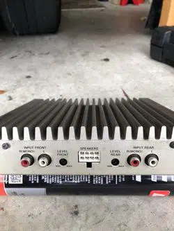
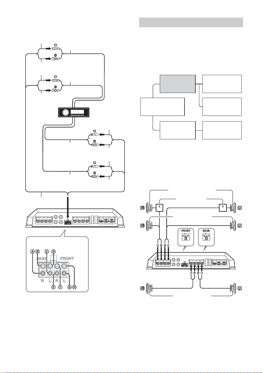
Input Connections
Front Rear
Left Right
7GB
High level input connection
With the speaker connection , , or
(page 7, 8)
Note
Also, refer to the manual supplied with your car audio
unit for further details.
Set the FILTER selector switch on the control panel
to “HP” (high-pass filter), “LP” (low-pass filter) or
“OFF” according to the speaker system.
Also, refer to the manual supplied with your
speakers for further details.
Recommended high-resolution audio
system
Note
Certain products shown in the diagram may not be
available in your country or region.
6-speaker system (recommended for
the high-resolution audio system)
With the input connection or (page 6, 7)
Gray
Gray/Striped
White
White/Striped
Green
Green/Striped
Purple
Purple/Striped
Front left speaker
output
Front right speaker
output
Rear right speaker
output
Rear left speaker
output
High Level Input Connector
Speaker Connections
Hi-Res Audio
supported car audio unit
(e.g. RSX-GS9)
XM-GS4
(this unit)
Power amplifier
(e.g. XM-GS100)
Super tweeter
(e.g. XS-GS1)
Full-range speaker
(e.g. XS-GS1621)
Subwoofer
(e.g. XS-GSW121D)
Front speaker (min. 4 Ω)
Rear speaker (min. 2 Ω)
Crossover network
Front super tweeter (min. 4 Ω)
8GB
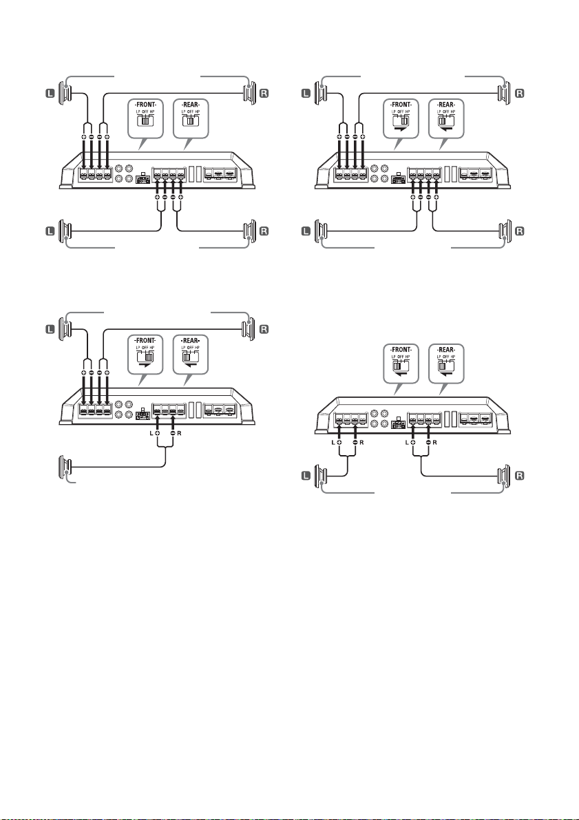
4-speaker system
With the input connection or (page 6, 7)
3-speaker system
With the input connection or (page 6, 7)
Notes
In this system, the volume of the subwoofer will be
contro
lled by the car audio unit fader control.
In this system, the output signals to the subwoofer
will be
the combination of both the REAR L INPUT and
REAR R INPUT jacks or the REAR high level input
connector signals.
2-way system
With the input connection or (page 6, 7)
Note
In this system, the volume of the subwoofer will be
control
led by the car audio unit fader control.
2-subwoofer system
With the input connection (page 6)
Front speaker (min. 2 Ω)
Rear speaker (min. 2 Ω)
Full range speakers (min. 2 Ω)
Subwoofer (min. 4 Ω)
Full range speakers (min. 2 Ω)
Subwoofer (min. 2 Ω)
Subwoofer (min. 4 Ω)
9GB
Precautions
This unit is designed for negative ground (earth)
12 V DC operation only.
Use speakers with an impedance of 2 to 8 Ω (4 to
8 Ω when
used as a bridging amplifier).
Do not connect any active speakers (with built-in
amplif
iers) to the speaker terminals of the unit.
Doing so may damage the active speakers.
Avoid installing the unit in areas subject to:
high temperatures such as from direct sunlight
or hot ai
r from the heater
rain or moisture
dust or dirt.
If your car is parked in direct sunlight and there is
a
consi
derable rise in temperature inside the car,
allow the unit to cool down before use.
When installing the unit horizontally, be sure not
to cove
r the fins with the floor carpet, etc.
If this unit is placed too close to the car audio unit
or antenna
(aerial), interference may occur. In this
case, relocate this unit away from the car audio
unit or antenna (aerial).
If no power is being supplied to the car audio
unit, chec
k the connections.
This power amplifier employs a protection circuit*
to prot
ect the transistors and speakers if the
amplifier malfunctions. Do not attempt to test the
protection circuits by covering the heat sink or
connecting improper loads.
Do not use the unit on a weak battery as its
optimum p
erformance depends on a good power
supply.
For safety, keep your car audio unit volume
modera
te so that you can still hear other sounds.
* Protection circuit
This amplifier is provided with a protection circuit that
operat
es in the following cases:
when the unit overheats
when a DC current is generated
when the speaker terminals are short-circuited.
The ill
umination indicator will change from white to
red, a
nd the unit will shut down. If this happens, take
out the cassette tape or disc, turn off the connected
equipment, and determine the cause of the
malfunction. If the unit has overheated, wait until it
cools down before use.
If you have any questions or problems concerning
your unit that are not covered in this manual,
please consult your nearest Sony dealer.
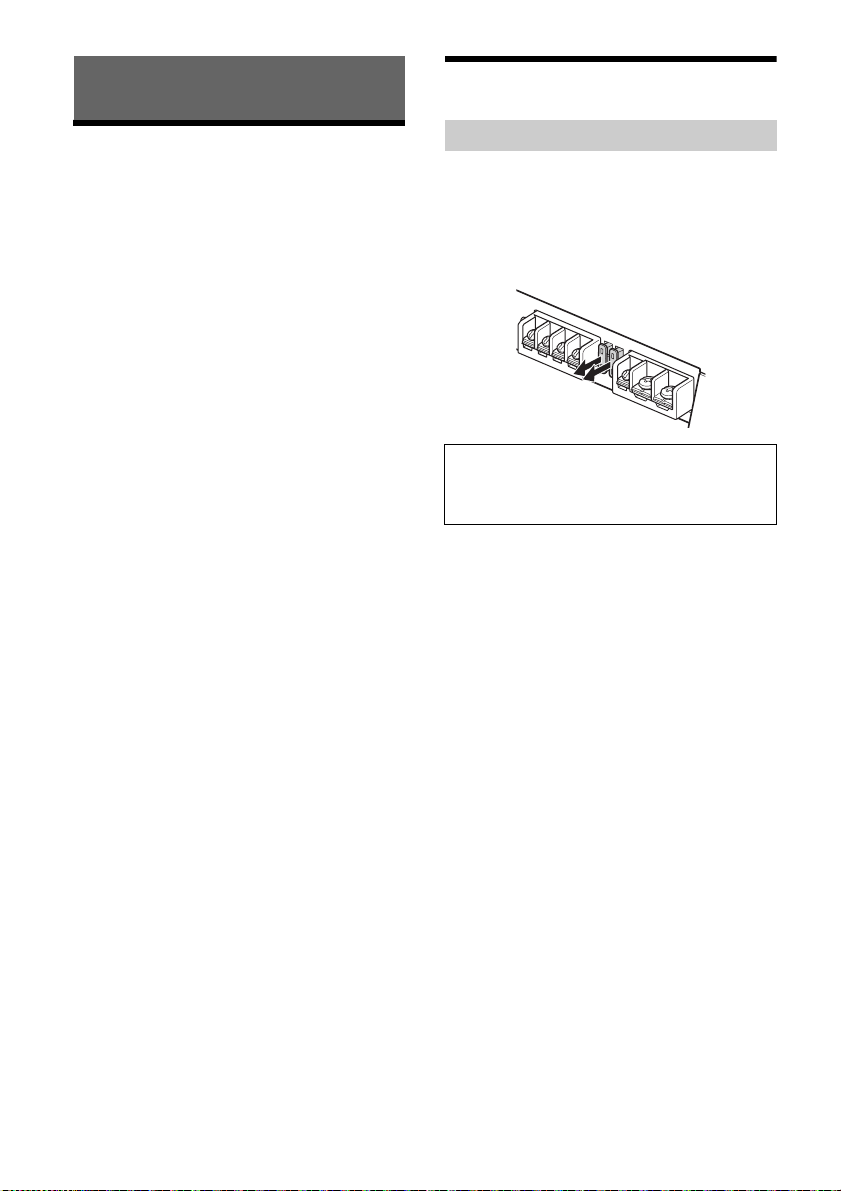
Maintenance
When replacing the fuse, be sure to use one
matching the amperage stated above the fuse
holder. If the fuse blows, check the power
connection and replace both the fuses. If the fuse
blows again after replacement, there may be an
internal malfunction. In such a case, consult your
nearest Sony dealer.
Additional Information
Fuse Replacement
Warning
Never use a fuse with an amperage rating
exceeding the one supplied with the unit as this
could damage the unit.
10GB
Specifications
AUDIO POWER SPECIFICATIONS
CEA2006 Standard
Power Output: 70 Watts RMS × 4 at
4 Ohms < 1% THD+N
SN Ratio: 93 dBA
(reference: 1 Watt into 4 Ohms)
Circuit system
OTL (output transformerless) circuit,
Pulse power supply
Inputs
RCA pin jacks,
High level input connector
Input level adjustment range
0.3 – 6 V (RCA pin jacks),
3 – 12 V (High level input)
Outputs
Speaker terminals
Speaker impedance
2 – 8 Ω (stereo),
4 – 8 Ω (when used as a bridging amplifier)
Maximum output
2 Speakers: 350 W × 2 (at 4 Ω)
4 Speakers: 150 W × 4 (at 4 Ω)
Rated output
(supply voltage at 14.4 V, 20 Hz – 20 kHz, 1 %
TH
D)
2 Speak
ers: 160 W × 2 (at 4 Ω)
4 Speakers: 80 W × 4 (at 2 Ω),
70 W × 4 (at 4 Ω)
Frequency response
10 Hz – 100 kHz ( dB)
Harmonic distortion
0.05 % or less (at 1 kHz, 4 Ω)
Low-pass filter
50 – 300 Hz, 12 dB/oct
High-pass filter
50 – 300 Hz, 12 dB/oct
Subsonic filter
6 – 70 Hz, 12 dB/oct
Low boost
0 – 10 dB (40 Hz)
Power requirements
12 V DC car battery (negative ground (earth))
Power supply voltage
10.5 – 16 V
Current drain
At rated output: 33 A (4 Ω, 70 W × 4)
Remote input: 1 mA
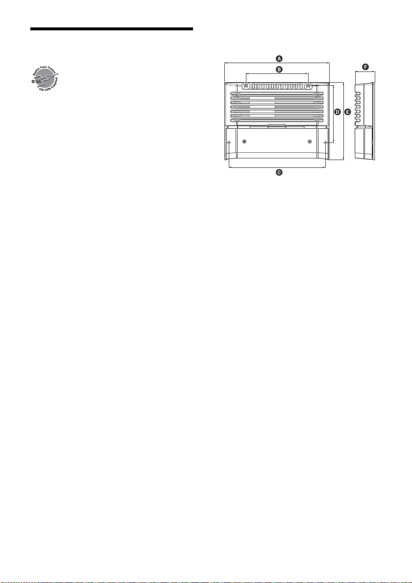
Dimensions
Approx. 272 × 51 × 202 mm (10
3
/4 × 2
1
/8 × 8 in)
(w/h/d) not incl. projecting parts and controls
272 mm (10
3
/4 in)
162 mm (6
1
/2 in)
251 mm (10 in)
149.5 mm (6 in)
202 mm (8 in)
51 mm (2
1
/8 in)
Mass
Approx. 2.7 kg (6 lb) not incl. accessories
Package contents:
Main unit (1)
Mounting screws (4)
High level input cord (1)
Your dealer may not handle some of the above
l
isted
accessories. Please ask the dealer for detailed
information.
Design and specifications are subject to change
withou
t notice.
+0.5
−
3.0

11GB
Troubleshooting
The following checklist will assist in the correction
of most problems which you may encounter with
your unit. Before going through the checklist below,
refer to the connection and operating procedures.
The illumination indicator does not light up.
The fuse is blown.
Replace the fuse with a new one.
The ground (earth) wire is not securely
connect
ed.
Fasten the ground (earth) wire securely to a
metal
point of the car.
The voltage going into the remote input (REM)
term
inal is too low.
Turn on the car audio unit if it is not turned on.
Use a relay if the system employs too many
ampl
ifiers.
Check the battery voltage (10.5 – 16 V).
The illumination indicator changes from white to
red.
Turn off the power switch. The speaker outputs
have shorted.
Rectify the cause of the short.
Turn off the power switch. Make sure the speaker
cord
and ground (earth) wire are securely
connected.
The unit becomes abnormally hot.
The unit heats up abnormally.
Use speakers with suitable impedance: 2 – 8 Ω
(stere
o), 4 – 8 Ω (when used as a bridging
amplifier).
Make sure to place the unit in a well ventilated
locati
on.
The sound is interrupted.
The thermal protector has activated.
Reduce the volume.
Alternator noise is heard.
The power connecting wires are installed too
close to the RCA pin cords.
Keep the wires away from the cords.
The ground (earth) wire is not securely
connect
ed.
Fasten the ground (earth) wire securely to a
metal
point of the car.
Negative speaker wires are touching the car
chassi
s.
Keep the wires away from the car chassis.
The sound is muffled.
The filter switch is set to “HP” or “OFF”.
When connecting the subwoofer, set to “LP”.
The filter switch is set to “LP”.
When connecting the full range speaker, set to
“OFF” o
r “HP”.
The sound is too quiet.
The LEVEL adjustment control is not appropriate.
Turn the LEVEL adjustment control in the
clockwise direction.
If these solutions do not help improve the situation,
consult your
nearest Sony dealer.
12GB
This warranty is valid only in the United States.
W 444774902