
3
Before operating this projector, please read this manual carefully and completely.
This manual will provide you with the basic instructions for operation of the
projector. Installation, preliminary adjustments and procedures which require the
opening of the projector and contact with electrical components should be
performed by service personnel. For continued safe and reliable operation, use
only cables supplied by the manufacturer for power. Adhere to all notes and
warnings.
Features
© Multi scan circuit automatically locks on video, superdata from 15 to 69 kHz
(PG-6200/6200G) and graphics signals from 15 to 100 kHz (PG-9200/
9200G).
You can interface video and high resolution RGB signals from various
computers, workstations and graphics boards.
© 7" CRTs with deflection angle 90 degrees produce a detailed picture with a
resolution of 160021200 pixels(PG-9200/PG-9200G) and 128021024 pixels
(PG-6200/PG-6200G).
© Newly developed video output circuit makes possible 100 MHz of Video
Bandwidth and 1000 lumens of light output.
© ECP lens produces an image with true color reproduction.
© AKB circuit provides stable white balance.
© Display size can be altered to accommodate any picture size from 60" to 300"
diagonal. In addition to ceiling mounting, floor, desk top and rear installations
are possible. (The ceiling mounting kits can be purchased as an optional item
for ceiling installation.)
© Digital point convergence provides high accuracy for a projecting fine graphic
displays. (This can be purchased as an optional item for the PG-6200/PG-
6200G.)
© On-screen menus provide easy access to adjustment items.
© ISS-6010/ISS-6010G interface allows 10-100 inputs.
© Video system compatible with NTSC, PAL, SECAM and NTSC 4.43.
© Up to 100 convergence patterns can be stored in the stand alone mode in
digital memory.
© Quick copy convergence for fast easy set up from one pre-set signal.
© Built in self diagnostics for on-sight troubleshooting.
© Built in “CROSS HAIR”, “CROSS HATCH”, “DOT”, “WINDOW” and “H
(FOCUS)” test patterns for accurate setup.
© Source information status display.
© The SEQUENCER function allows the projector to automatically select input
signals one after another as programmed by the user.
12345
6
12345
6
12345
6
12345
6
12345
6
123456
INTRODUCTION.

4
INTRODUCTION
Important Safeguards
The following are important safety instructions designed to ensure the long life
of your projector and to prevent fire and shock hazards. Be sure to read these
safety instructions carefully and follow all warnings given below.
Installation
The projector must be installed by trained personnel.
Place the projector on a flat, level surface and in a dry area free from dust and
moisture. Do not place the projector in direct sunlight, near stoves or other heat
radiating appliances. Smoke, steam and exposure to direct sunlight could ad-
versely affect the internal components. Avoid rough handling when moving your
equipment as a strong shock could damage its internal components. If installing
the projector on the ceiling, use only optional ceiling kits (two types) supplied by
the manufacturer. Observe all instructions and warnings. Since installing the
projector on the ceiling requires special techniques and a optional ceiling kit,
users must not try to install it. Contact your dealer for ceiling installation.When
ordering the ceiling kit, specify the part name, PG CMKIT-F or PG CMKIT.
Power supply
The PG-6200 and PG-9200 projector are designed to operate on 120 V 60 Hz,
and the PG-6200G and PG-9200G are designed to operate on 220-240 V 50 Hz
AC power supply. Make sure your local power supply matches these require-
ments before operation.
Handle the power cord carefully and avoid excessive bending. A damaged cord
may cause electric shock or fire. If the projector is not to be used for an extended
period, remove the plug from the power outlet.
Cleaning
Unplug the projector from the power outlet before cleaning.
Clean the cabinet and front panel periodically with a soft cloth. If heavily stained,
use a mild detergent solution. Never use strong detergents or solvents such as
alcohol or thinner to clean your projector.
Lens cleaning: Avoid touching the lens surfaces.
Special coating is applied to the lens surfaces.
Consult your dealer for lens cleaning.
Fire and Shock Precautions
Adequate ventilation must be provided to prevent heat build-up inside the
projector. Make sure the ventilation holes are unobstructed.
Keep the inside of the projector free from foreign objects, such as paper clips,
nails, paper, etc. Do not attempt to retrieve such objects yourself or insert metal
objects such as wire and screw-drivers inside the projector. If a hazardous object
falls inside the projector, unplug it immediately and call a qualified electrical
repairman for removal.
Do not set liquids on top of the projector.
4
12345
6
12345
6
12345
6
12345
6
12345
6
123456
PART NAMES AND FUNCTIONS.
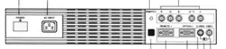
Front Terminal Panel
REMOTE 2
R
G
B
H / V
V
R
EMOTE 1
OPTION 1
S-VIDEO
V
IDEO
POWER
AC INPUT
ACAT
H/V&V
HIGH 75
W
1POWER Switch (Main power)
Press to turn the main power on. The STANDBY indica-
tor will light.
In this condition you can start up the projector by pressing
the POWER ON button on the remote control or the
POWER button on the rear panel.
Press again to turn the main power off.
NOTE: When turning off the main power, first return the
projector to the standby condition by pressing the
POWER OFF button on the remote control or the POWER
button on the rear panel and then turn off the main
POWER switch. These procedures are to protect your
projector and the connected equipment.
2AC INPUT
Connect the supplied power cord here.
3REMOTE 2 Jack
The supplied full function remote control is connected
here. The wireless control does not work when the remote
cable plug is inserted here.
4R,G,B, H/V and V Input Terminals
Connect R, G, B, H (Horizontal sync) and V (Vertical
sync) outputs of the external equipment (such as the
Switcher). If using a component with a combined sync
(SYNC) output, connect it to the H/V terminal.
5Remote Sensor
Receives the infrared signal from the supplied remote
control when used in the wireless mode.
6REMOTE 1 Terminal
This terminal allows external control of the projector
either from the Switcher or from an external control.
When using the Switcher, connect to the REMOTE 1
terminal on the back of the Switcher.
NOTE: The ISS-6010/ISS-6010G Switcher is compatible
with this projector.
7OPTION 1 Input Terminal
For future system expansion.
8S-VIDEO Input Terminal
Connect to the S-video output of the external equipment
such as VCR with an S-video output. This terminal allows
switching between S2 and S1 VIDEO input modes.
9H/V, V Impedance Switch(HIGH/75 Ω)
Selects the impedance of the H/V and the V terminals. In
normal operation, set at the “75Ω” position.
Slide the switch to the “HIGH” position when inputting a
TTL signal.
0VIDEO Input Terminal
Connect to the video output of the external equipment
such as a VCR or laser disk player.
AACAT Terminal
This is a video output connector for the optional built-in
CCD camera, which is needed to execute the automatic
convergence with the optional ACAT software.
1
2
3
4
A
8 9 0765
5
PART NAMES AND FUNCTIONS
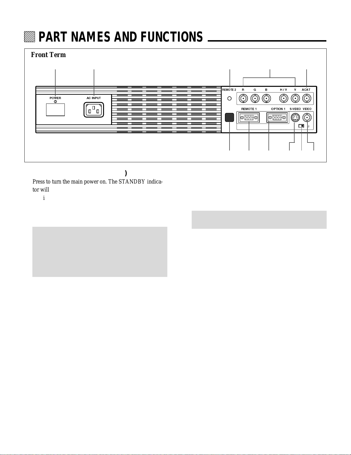
BPOWER Button
Turns the projector on or off when the projector is in the
standby condition (Main Power switch must be on and the
Standby indicator lit).
CCONTROL Button
Used with other buttons, similar to a shift key on a
computer. This is referred to as the CTL button in this
manual and has the same function as the CTL button on
the remote.
DOPERATE Button
Press to display the OPERATE menu. You can select the
following adjustment functions from this menu.
1/ PICTURE 4/ INPUT SELECT
2/ POSITION 5/ SOURCE INFO
3/ SOUND 6/ STATIC
NOTE: ”3/SOUND” is not included in stand alone operate
menu.
EENTER Button
Executes menu selection and switches input.
FEND Button
Exits the adjustment mode.
GDOWN Button
Used to decrease values or move the cursor downward.
When used with the CONTROL button, the DOWN
button works as the CURSOR button on the remote
control unit.
HUP Button
Used to increase values or move the cursor upward. When
used with the CONTROL button, the UP button works as
the CURSOR button on the remote control unit.
INORMAL/LOAD Button
Returns the adjustment data to the standard level (factory
preset level). While holding down the CONTROL button,
press the NORMAL button to display the “LOAD/
CANCEL” menu to select either LOAD (last stored level)
or CANCEL (data cancelled).
JTwo Digit Display
Displays projector error codes. (“00” in normal operation)
KREMOTE Indicator
Flashes to acknowledge when the projector receives a
signal from the remote control.
LSTANDBY Indicator
Lights up when the projector’s main POWER switch is
on. Flashes when the projector might not be connected
with the Switcher correctly or when the Switcher is turned
off.
MPOWER Indicator
Lights up when the projector is turned on.
NRemote Sensor
Receives the signal from the supplied remote control
when used in the wireless condition.
Rear Control Panel
UP
NORMAL
/ LOAD
DOWNENDENTEROPERATECONTROLPOWER
POWERSTANDBYREMOTE
BC
D
EF GHI J KLM N
6
PART NAMES AND FUNCTIONS
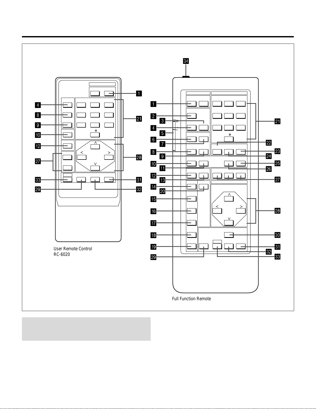
Remote control unit
POWER
ON OFF
OPERATE
PICTURE
MUTE
SOUND
MUTE
1 ABC 2 DEF 3 GHI
4 JKL 5 MNO 6 PQR
7 STU 8 VWX 9 YZ /
10 ,.
R
B
ENDCTL
DISPLAY
STATIC
NORMAL ENTER
1 ABC 2 DEF 3 GHIOFFON
4 JKL 5 MNO 6 PQRTEST
7 STU 8 VWX 9 YZ/
ADJUST
OPERATE
10 ,.
SOUND FUNC
PIC FUNC
HELP INFO
INPUT LIST
SOUND MUTE
PIC MUTE
POSITION
KELVINFOCUS
DISPLAY
RGBPOINTSTATIC
PHASETILT
BOW
AMPLIT
LINEAR
STORE
KEYSTN
CTL ENTER END
NORMAL
PINCUS
POWER INPUT
CURSOR
ON
OFF
1
K
R
U
V
S
W
Q
B
0
9
8
4
X
K
L
N
M
P
O
Q
R
T
V
U
W
1
2
3
4
5
6
7
8
9
0
A
B
C
D
J
E
F
G
H
I
S
User Remote Control
RC-6020
Full Function Remote Control
RC-6051
NOTE: The full function remote control is designed for setup
adjustment. Use the user remote control for normal
operation.

7
PART NAMES AND FUNCTIONS
1POWER Buttons (ON/OFF)
Press the ON button to turn the projector on when the
projector is in the standby condition (STANDBY indica-
tor lit). Press the OFF button to return the projector to the
standby condition.
2TEST Button
Press to display the “TEST PATTERN” menu from which
you can select a test pattern.
3ADJUST Button
Press to display the “ADJUST” menu.
4OPERATE Button
Press to display the “OPERATE” menu.
5Backlight Switch
Turns the backlight on and off.
If another button operation is not made within 30 seconds
during the Backlight ON, the Backlight is normally turned
off to conserve the batteries.
6PIC FUNC Button
Press to display the picture adjustment screen.
NOTE: Some function items will not be available
depending on the type of video signal.
7SOUND FUNC Button
Press to display the VOLUME adjustment screen. You
can adjust the volume of the ISS-6010/ISS-6010G
Switcher.
8PICTURE (PIC) MUTE Button
Press to mute the picture. Press again to display the
picture.
9SOUND MUTE Button
Press to mute the sound. Press again to return the sound.
NOTE: This works only with the ISS-6010/ISS-6010G
Switcher.
0DISPLAY Button
Press to turn on or off the on-screen display. Pressing with
CTL eliminates the on-screen display; pressing with CTL
again restores it.
NOTE: Even if the on-screen display may be turned off
with pressing CTL and DISPLAY, any adjustment will
still change the projector’s memory settings. This mode
is available even when an input is switched to another or
the power is turned off using the POWER OFF button on
the remote control.
AFOCUS Button
Press to enter the FOCUS mode.
BSTATIC Button
Press to enter the STATIC mode. You can adjust the static
convergence.
CPOINT Button
(When the point convergence board installed)
Press to enter the POINT mode. You can adjust the point
convergence.
DTILT Button
Press to enter the TILT, SKEW mode. You can adjust the
tilt and the skew of the projected image.
EBOW Button
Press to enter the BOW mode. You can adjust the hori-
zontal and the vertical bow of the projected image.
FAMPLIT Button
Press to enter the AMPLITUDE mode. You can adjust the
horizontal width and the vertical height of the projected
image.
GLINEAR Button
Press to enter the LINEARITY mode. You can adjust the
horizontal and the vertical linearity of the projected
image. Pressing with CTL will bring you to the LINEAR-
ITY-BALANCE adjustment screen.
HKEYSTN Button
Press to enter the KEYSTONE mode. You can adjust the
horizontal and the vertical keystone of the projected
image. Pressing with CTL button will bring you to the
KEY-BALANCE alignment screen.

8
IPINCUS Button
Press to enter the PINCUSHION mode. You can adjust
the horizontal and the vertical pincushion of the projected
image. Pressing with the CTL button will bring you to the
PIN-BALANCE alignment screen.
JPHASE Button
Press to enter the PHASE mode. You can adjust the tilt
and cursor phase.
KINPUT Button
Selects menus and switches input signals.
LHELP Button
Press to display the explanation of the current selected
function and available functions.
MINPUT LIST Button
Press to display the memory list of the recorded input
signals.
NINFO Button
Press to display the various parameters and settings of the
currently displayed image. Pressing with the CTL button
displays some of items available in SETTING MODE.
OKELVIN Button
Press to enter the WHITE BALANCE mode. You can
adjust the white and the black level.
PPOSITION Button
Press to enter the position mode. You can adjust the
horizontal, vertical position and horizontal, vertical
blanking.
QR, G, and B Buttons
Turn each CRT beam on and off separately. When using
with the CTL button, you can select the CRT to be
adjusted during convergence and center focus adjust-
ments. Note that the G button is only on the full function
remote control.
RCURSOR Buttons
Used for increasing and decreasing control levels, cursor
movement and convergence adjustments.
SNORMAL Button
Returns the standard level for each signal. When pressed
once, the confirmation message will be displayed. When
“YES” is selected and ENTER is pressed, the data will be
returned to the standard level. While holding down the
CTL button, press the NORMAL button to display the
“LOAD/CANCEL” menu to select either LOAD (last
stored level) or CANCEL (data cancelled).
TSTORE Button
Memorizes the adjustments setting of each signal sepa-
rately.
When pressed once, the confirmation message “STORE?”
will be displayed. When selecting “YES” and ENTER, the
data will be stored in memory.
UEND Button
Ends the adjustment mode.
VENTER Button
Executes menu selection and switches to selected input.
WCTL Button
Used in conjunction with other buttons, similar to a shift
key on a computer.
XRemote Control Jack
Insert the plug of the supplied remote cable here when the
full function remote control is used in the wired condition.
PART NAMES AND FUNCTIONS
9
PART NAMES AND FUNCTIONS
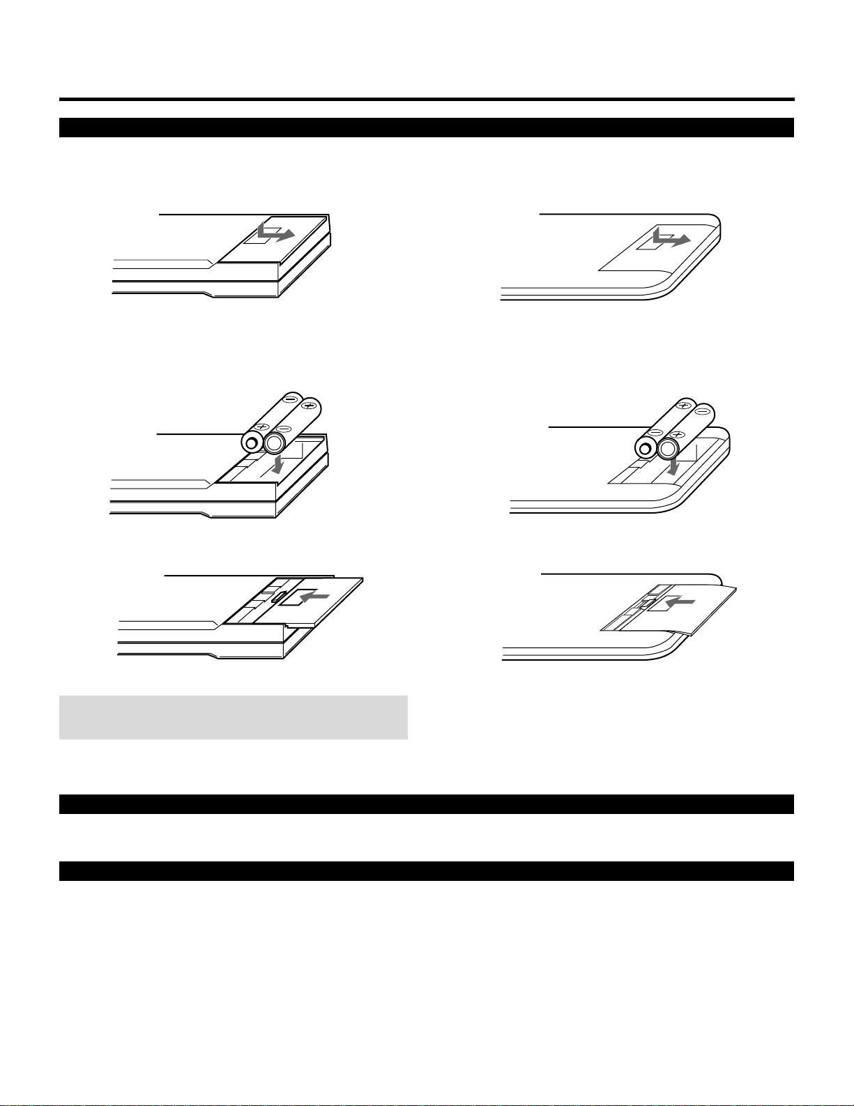
Battery installation and replacement
User remote control (RC-6020)
1 Press down on the battery compartment cover and slide
the cover in the direction of the arrow.
Full function remote control (RC-6051)
1 Press down on the battery compartment cover and slide
the cover in the direction of the arrow.
NOTE: The remote control is powered by two alkaline 1.5V
AA batteries.
3 Close the battery compartment cover.3 Close the battery compartment cover.
2 Install the two new batteries, making sure that their
polarity matches the , . diagrams inside the battery
compartment. Incorrect polarity could damage the unit.
2 Install the two new batteries, making sure that their
polarity matches the , . diagrams inside the battery
compartment. Incorrect polarity could damage the unit.
Remote control cautions
Use the remote control within a distance of about 7m (23 ft.) and at 30 degrees angle left and right.
Handling remote control and batteries
• Do not drop or mishandle the remote.
• Do not get the remote wet. If the remote gets wet, wipe it dry immediately.
• Avoid heat and humidity.
• When not using the remote for a long period, remove the batteries.
• Do not use new and old batteries together, or use different types together.
• Do not take apart the batteries, heat them, or throw them into a fire.
• Avoid using the full function remote control as wireless with the backlight switch ON for an extended period of time. This can
cause short battery life.
8
123456
12345
6
12345
6
12345
6
12345
6
12345
6
123456
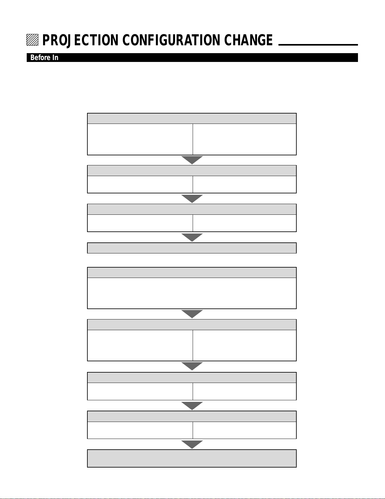
PROJECTION CONFIGURATION CHANGE.
Before Installation Change
The projector is electrically and mechanically set for 100 inch diagonal screen, front throw ceiling mount and a projection angle of
12 degrees. If your application is different from the factory setting(for example, ceiling to floor and screen size between 60 and 300
inch), you will have to reconfigure the projector for your application. Follow the change procedures according to the instructions
below.
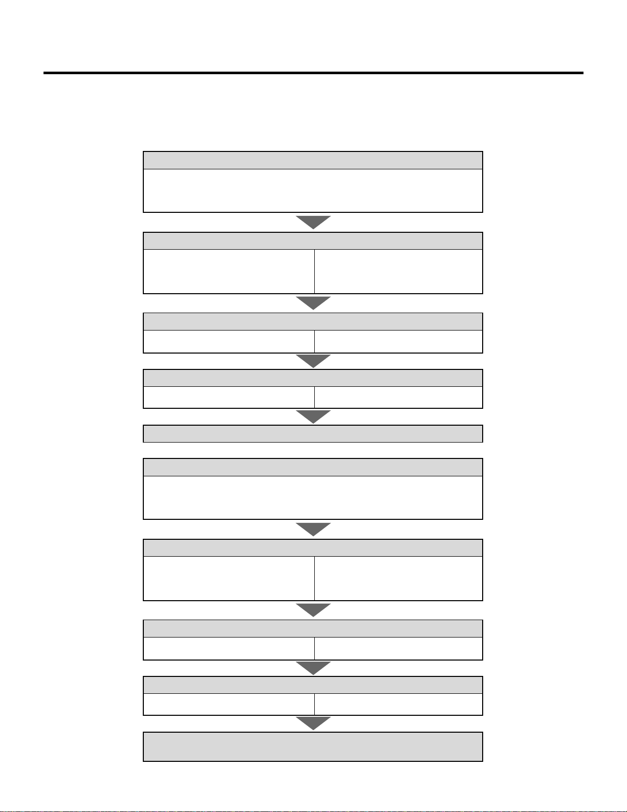
To change screen size only :
1) Set the focus ring to the proper position.
For 60" screen size
R –––A-2, B-2
G –––A-1, B-2
B –––A-2, B-2
For 200-300" screen size
R –––A-5, B-5
G –––A-1, B-5
B –––A-5, B-5
2) Adujust the angle of the CRT's.
For 60" screen size
Move the CRT to the 60 positon
For 200-300" screen size
Move the CRT to the 200 or 300 position
3) Adjust the decorative lens panel.
For 60" screen size
Adjust to match the 60 position
For 200-300" screen size
Adjust to match the 200 or 300 position
4) Degauss the projector. See “Degaussing” on page 64 in the set-up manual.
To change to the desk top system (front)
1) Reverse the scan.
H –––1-Red, 2-Blue
V –––1-Brown, 2-Yellow
A –––1-Blue, 2-Red
B –––1-Brown, 2-Yellow
2) Set the focus ring to the proper position.
For 60" screen size
R –––A-2, B-2
G –––A-1, B-2
B –––A-2, B-2
For 200-300" screen size
R –––A-5, B-5
G –––A-1, B-5
B –––A-5, B-5
3) Adujust the angle of the CRT's.
For 60" screen size
Move the CRT to the 60 positon
For 200-300" screen size
Move the CRT to the 200 or 300 position
4) Adjust the decorative lens panel.
For 60" screen size
Adjust to match the 60 position
For 200-300" screen size
Adjust to match the 200 or 300 position
5) Degauss the projector. Select installation type from ASTIG OUTPUT.
See “ASTIG OUTPUT” on page 62 in the set-up manual.
9
PROJECTION CONFIGURATION CHANGE
To change to the ceiling mount system (rear)
1) Reverse the scan.
H –––1-Red, 2-Blue
V –––1-Yellow, 2-Brown
A –––1-Blue, 2-Red
B –––1-Yellow, 2-Brown
2) Set the focus ring to the proper position.
For 60" screen size
R –––A-2, B-2
G –––A-1, B-2
B –––A-2, B-2
For 200-300" screen size
R –––A-5, B-5
G –––A-1, B-5
B –––A-5, B-5
3) Adujust the angle of the CRT's.
For 60" screen size
Move the CRT to the 60 positon.
For 200-300" screen size
Move the CRT to the 200 or 300 position
4) Adjust the decorative lens panel.
For 60" screen size
Adjust to match the 60 position
For 200-300" screen size
Adjust to match the 200 or 300 position
5) Degauss the projector. See “Degaussing” on page 64 in the set-up manual.
To change to the front desk top system (rear, 0 projection angle)
1) Reverse the scan.
H –––1-Blue, 2-Red
V –––1-Brown, 2-Yellow
A –––1-Red, 2-Blue
B –––1-Brown, 2-Yellow
2) Set the focus ring to the proper position.
For 60" screen size
R –––A-2, B-1
G –––A-1, B-1
B –––A-2, B-1
For 200-300" screen size
R –––A-5, B-1
G –––A-1, B-1
B –––A-5, B-1
3) Adujust the angle of the CRT's.
For 60" screen size
Move the CRT to the 60 positon.
For 200-300" screen size
Move the CRT to the 200 or 300 position
4) Adjust the decorative lens panel.
For 60" screen size
Adjust to match the 60 position
For 200-300" screen size
Adjust to match the 200 or 300 position
5) Degauss the projector. Select installation type from ASTIG OUTPUT.
See “ASTIG OUTPUT” on page 62 in the set-up manual.
10
PROJECTION CONFIGURATION CHANGE
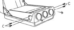
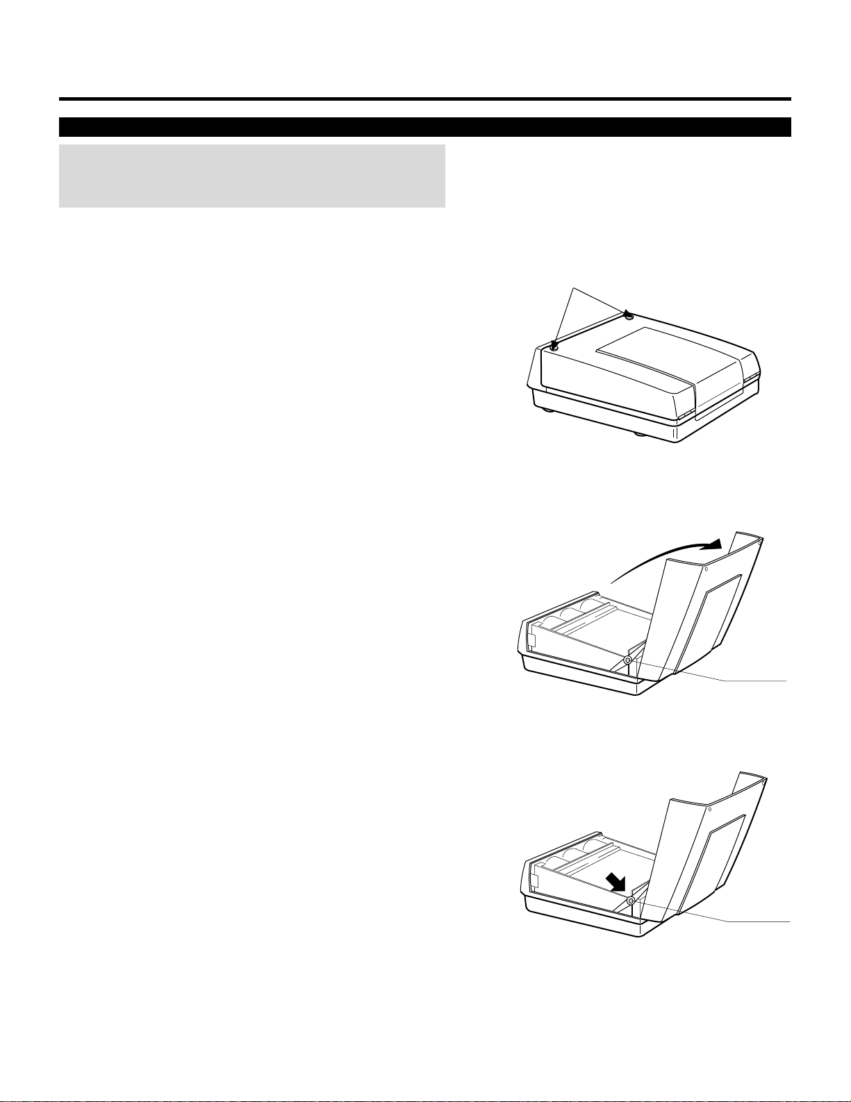
Opening Top Cover
CAUTION:
• Be sure to turn off the projector and unplug the power cord before
opening the top cover.
To open the top cover, proceed as follows:
1 Loosen two screws A.
• A is a retaining screw.
A
3 To close it, push the hinges in the direction of the arrow, then,
close the top cover.
4 Tighten the two A screws.
Hinge
2 Raise the top front of the projector in the direction of the arrow.
• Be sure to open the top cover until the hinges lock.
Hinge
11
PROJECTION CONFIGURATION CHANGE
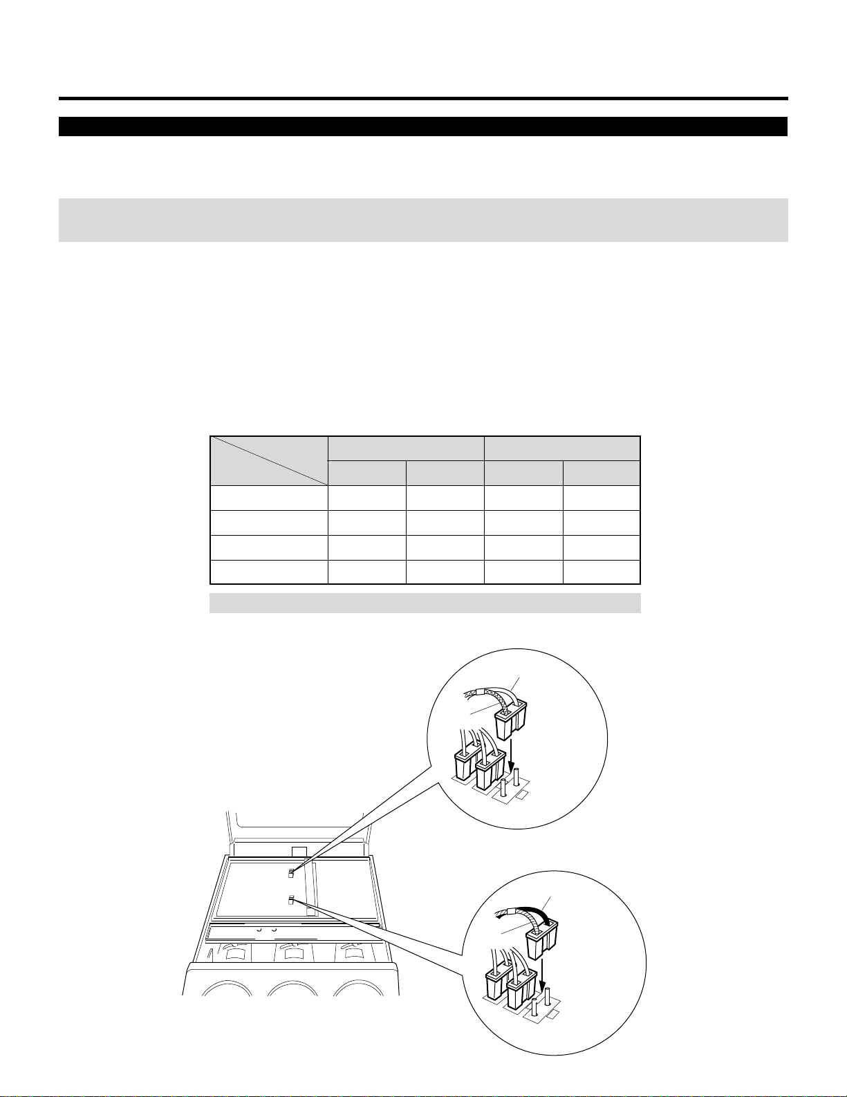
Scan Reversal
You will have to reverse the horizontal, vertical and convergence polarity when changing the projector’s configuration.
To reverse the scan, proceed as follows:
CAUTION: Always disconnect the projector from the AC source before reversing the plug. Failure to observe this precaution may
result in electric shock or damage to the projector.
1 Open the top cover.
• See Opening Top Cover section.
2 Reverse the vertical and horizontal scan.
• To reverse the scan there are two sets of plugs on the sweep board. VR, VG and VB are the vertical connectors(V=vertical and
RGB=color) and HR, HG and HB are the horizontal connectors(H=horizontal and RGB=color).
Remove the plug and turn it 180 degrees, then reinstall. Do this for all three of either horizontal or vertical connectors depend-
ing upon your application (See Table below)
1
VR
Brown
Vertical polarity
connector
Blue
Red
Horizontal polarity
connector
Yellow
2
VG
1
2
1
HB
2
1
HG
2
2
2
Horizontal and Vertical polarity
Connector pin
Setting
Ceiling front
Desk top front
Ceiling rear
Desk top rear
HR, HG, HB
1 Lead
Blue
Red
Red
Blue
2 Lead
Red
Blue
Blue
Red
VR, VG, VB
1 Lead
Yellow
Brown
Yellow
Brown
2 Lead
Brown
Yellow
Brown
Yellow
NOTE: The table is for non mirror applications.
12
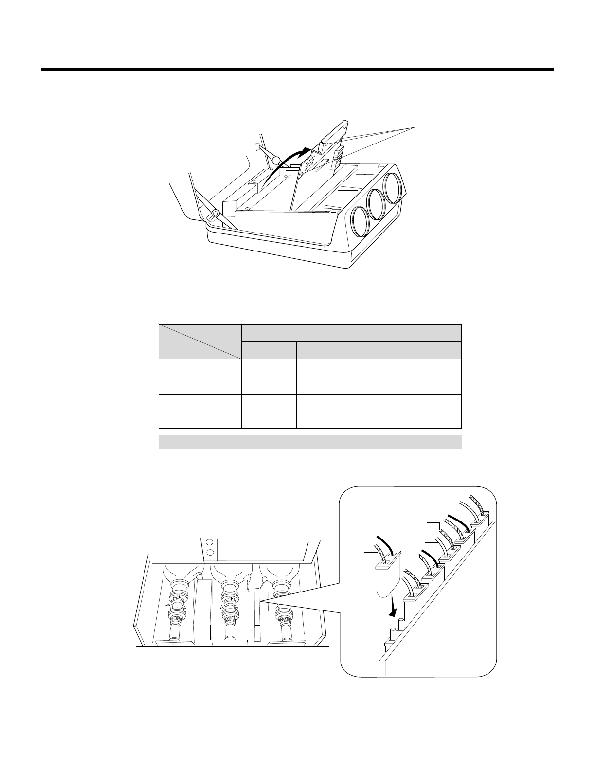
PROJECTION CONFIGURATION CHANGE
3 Loosen the four screws B, then lift the upper chassis(DFC).
• B is a retaining screw.
4 Reverse the convergence connectors (AR, BR, AG, BG, AB and BB) on CONV-DRIVE.
See Table below.
Connector pin
Setting
Ceiling front
Desk top front
Ceiling rear
Desk top rear
AR,AG,AB
1 Lead
Red
Blue
Blue
Red
2 Lead
Blue
Red
Red
Blue
BR, BG, BB
1 Lead
Yellow
Brown
Yellow
Brown
2 Lead
Brown
Yellow
Brown
Yellow
NOTE: The table is for non mirror applications.
Convergence polarity change
1
2
Red
Blue
Yellow
Brown
BR
AG
BG
AB
BB
AR
5 Close the upper chassis (DFC). Tighten the four screws B.
B
13
C
C
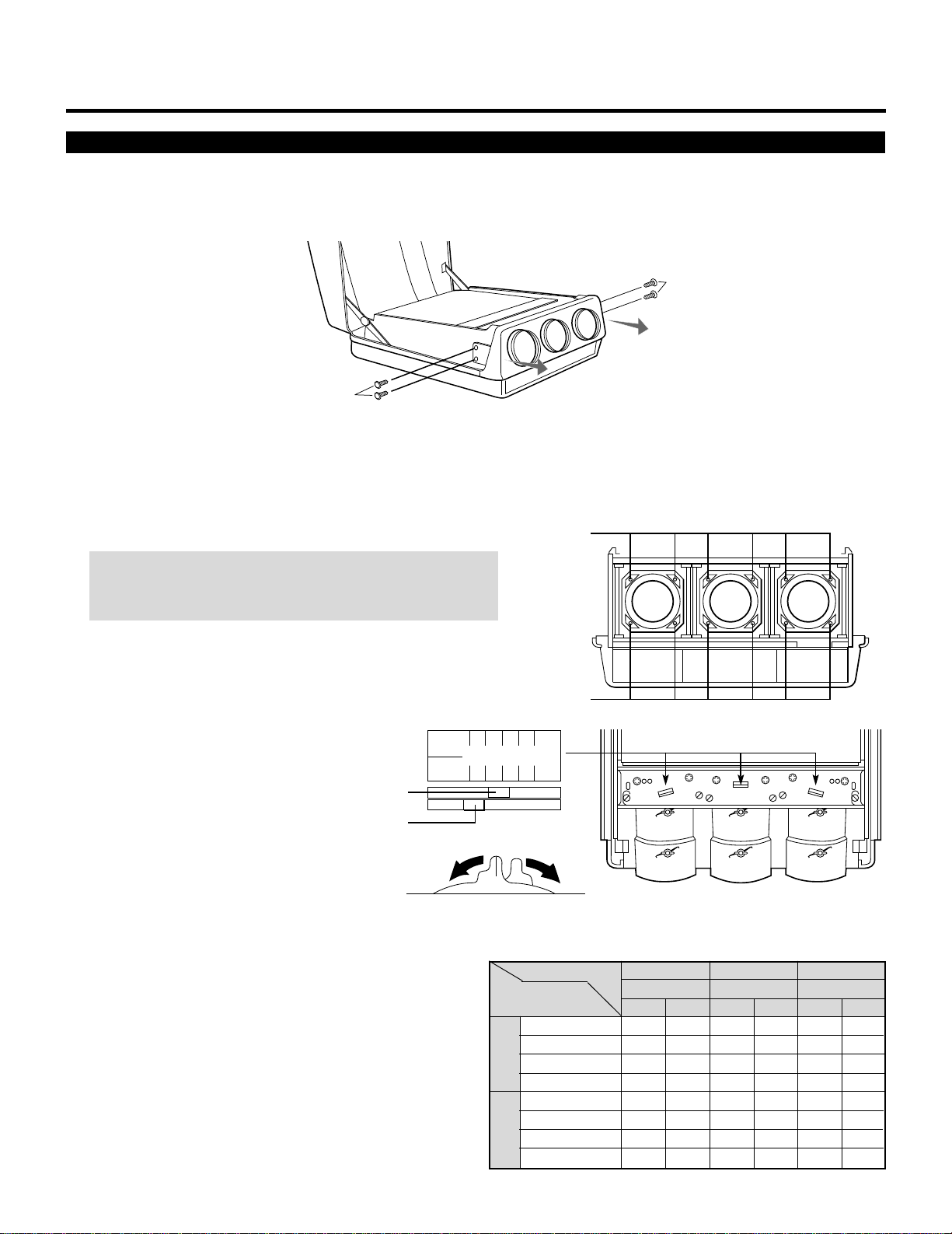
PROJECTION CONFIGURATION CHANGE
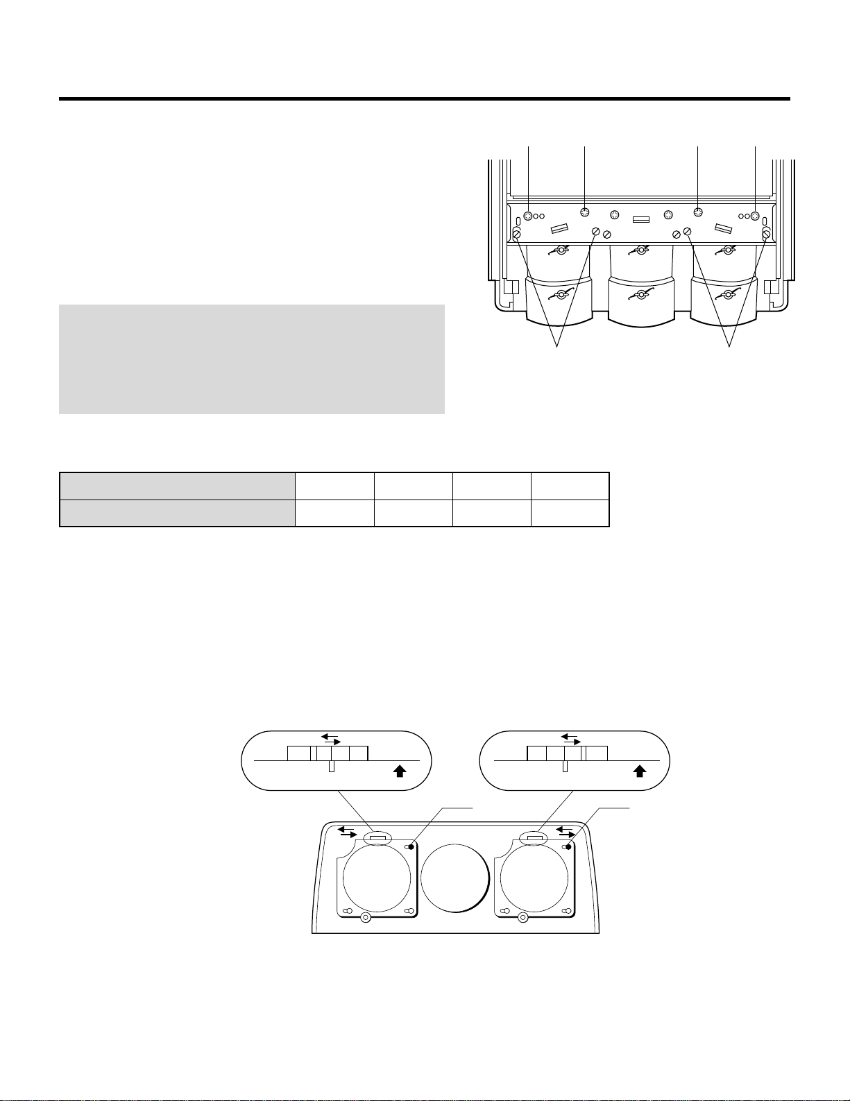
Screen Size Change(Adjusting Focus Rings and CRT Angle)
The projector can project an image from 60 to 300 inches diagonal. From the factory the projector is set for ceiling mount, 100 inch
diagonal screen size and a projection angle of 12 degrees. The projector can be used in either 12 or zero degree application.
Before the following procedures, remove the front panel by removing the four screws C whitch hold the front panel. There are two
screws on each side.
CRT
Projection angle
and screen size(Diagonal)
R
Knob
G
Knob
B
Knob
AB
ABAB
2
3
4
5
2
3
4
5
2
3
4
5
1
1
1
1
1
1
1
1
1
1
1
1
2
3
4
5
1
1
1
1
2
3
4
5
2
3
4
5
2
3
4
5
1
1
1
1
60" – 90"
91" – 130"
131" – 170"
171" – 300"
60" – 90"
91" – 130"
131" – 170"
171" – 300"
Position of Knobs3 Tighten the four screws at the lens.
• Adjusting Focus Rings
There are three sets of adjusting focus rings, two between each CRT and lens.
These focus rings are used for maintaining optimum edge focus for the various screen sizes and projection angles.
*When setting the focus rings or changing CRT angle, you must first remove the front panel.
screws
screws
CAUTION: Be careful not to remove any of the four screws
completely. The falling lens can cause serious injury especially
when the projector is installed on the ceiling.
1 Loosen the four screws at the lens.
300200
100
60-300
300200
100
60-300
1 2 3 4 5
A
B
knob A
knob B
Rotate
2 Rotate and set the knobs (A and B) to
the right position. The table below lists
which position the knob should be set to
for any given screen size and angle. The
similar table is also on the back of the
top cover.
0°
12°
14
PROJECTION CONFIGURATION CHANGE
• Adjusting Angle of CRTs
To adjust the angle of the CRTs, remove screws G and loosen screws
E and F.
Now you can move the tube and lens assembly to one of the three
other positions. Then replace screws G and tighten screws E and F.
This process needs to be done for the red and blue CRTs. The green
CRT is never repositioned. Use the table below to select the proper
setting for your screen size.
NOTE: The threaded hole marked “60-300” is drilled lengthwise so
you can move the CRT assembly to any screen size. Adjust the red
and blue lens so that the red or blue beam is aligned with the green
beam. After doing this, adjust the static convergence and the lens
focus (see the next page).
Then tighten the screws G.
300200
100
60-300
300200
100
60-300
E E
G F F G
Metal impression stamp screen size
Range of screen size (diagonal)
60-300
60"-300"
100
100"
200
200"
300
300"
• Adjusting Decorative Lens Panels
Before replacing the front panel adjust the decorative lens panels to
match the screen size so that they do not touch the lens barrels or
interfere with the normal operations of the lens.
Loosen the two screws at the top on the two left and right decorative
lens panels, then slide the panels to match the screen size.
• Tighten the screws after completing the above procedures.
• Reinstall the front panel, then replace and tighten the four screws.
300 60
UP
30060
UP
Decorative lens panels
screw screw
15
PROJECTION CONFIGURATION CHANGE
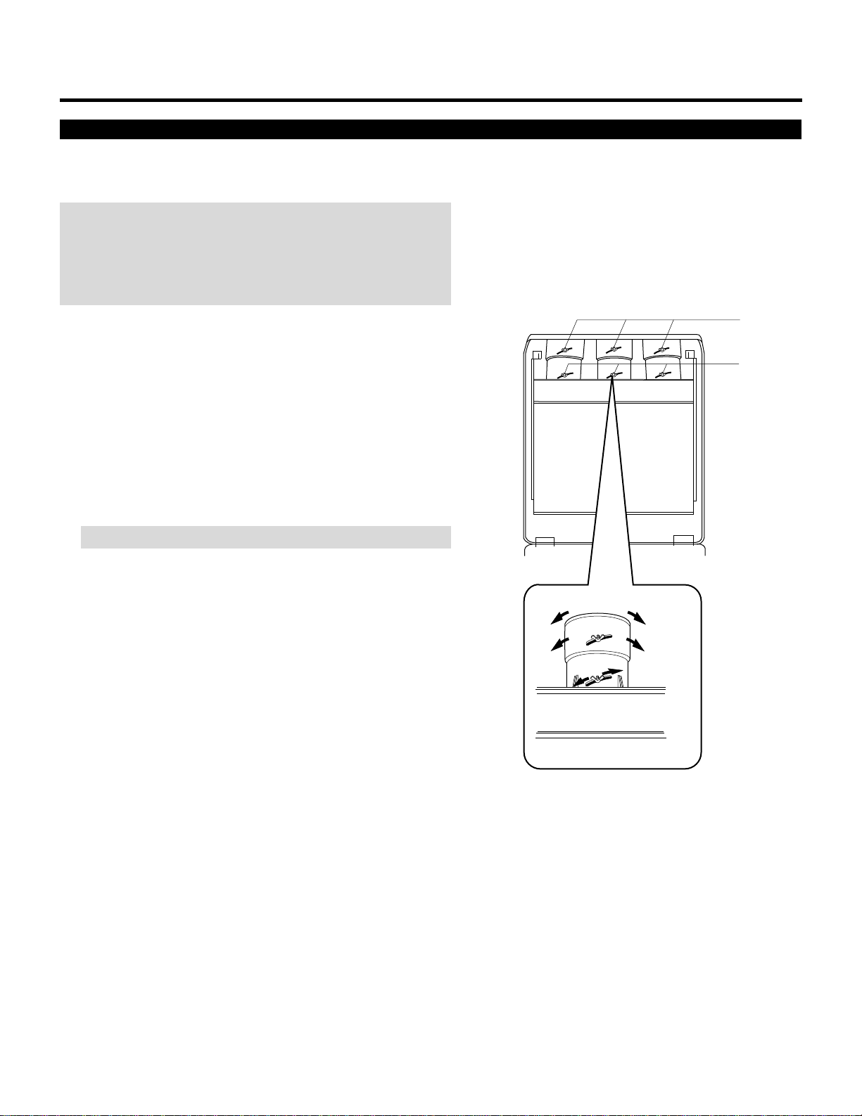
Lens Focus Adjustment
Adjust the center focus and edge focus mechanically to obtain the
best screen focus.
NOTE:
• Plug the power cord and turn on the projector before adjustment.
• The lens focus adjustment must be performed for each lens.
• Select the FOCUS test pattern using the TEST button on the full
function remote control.
Proceed as follows:
1 Press the R, G, or B button on the full function remote control to
project the CRT beam to be adjusted.
• You can turn on or off each CRT beam(R, G and B)separately.
2 Adjust the CENTER focus.
• Loosen the wing nut A. Rotate the lens using the wing nut A
until the center of the screen is in focus.
When you get the best center focus, tighten the wing nut A.
NOTE: Do not over-tighten the wing nut.
3 Adjust the EDGE focus.
• Loosen the wing nut B. Rotate the lens barrel until the edge area
of the screen is focused. Tighten the wing nut B.
4 Recheck center focus.
• If it is out of focus, repeat steps 2 and 3.
5 Repeat steps 1 to 4 for the other CRTs.
6 Close the top cover.
Wingnut B
Wingnut A
B
A
EDGE Focus
CENTER Focus
10
12345
6
12345
6
12345
6
12345
6
12345
6
123456
EXAMPLES OF CONNECTIONS.
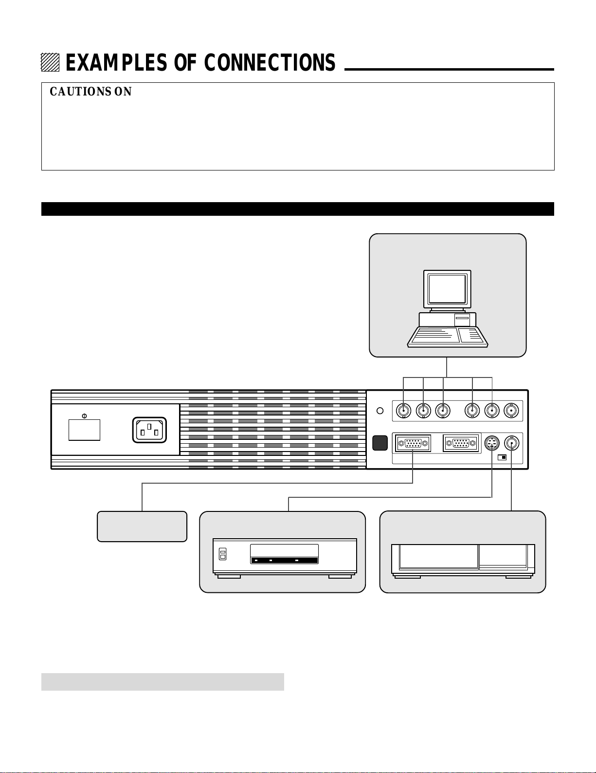
CAUTIONS ON CONNECTIONS:
• Unplug the projector and other equipment from the AC
supply before making connections.
• Make sure that the plug of the power cord is properly
connected to the power outlet. A loose connection may cause
hum or noise.
• Confirm your connection layout with the user’s manual
accompanying the equipment to be connected with the ISS-
6010/ISS-6010G Switcher.
NOTE: This projector does not have built-in speakers.
• Make sure that the STANDALONE mode is selected from the CONNECT CONDITION menu. Contact your dealer for the
information in detail.
When Used in Stand Alone Operation
REMOTE 2
R G B H / V V
REMOTE 1 OPTION 1
S-VIDEO VIDEO
POWER AC INPUT
ACAT
H/V&V
HIGH 75Ω
Components with RGB and H/V SYNC
outputs such as a personal computer
VCR or Video disc player
VCR with S-Video outputs
External Control
11
EXAMPLES OF CONNECTIONS
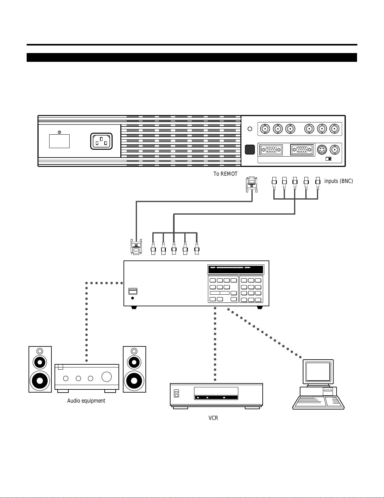
When Used with One Switcher (ISS-6010/ISS-6010G)
Up to 10 input signals can be accepted when the projector is connected to one Switcher. Using the projector with the Switcher
allows easy adjustment and signal selection.
• Make sure that the SW1 LEVEL mode is selected from the CONNECT CONDITION menu. Contact your dealer for the informa-
tion in detail.
• For more information on the Switcher, refer to the user’s manual accompanying the ISS-6010/ISS-6010G Switcher.
• All cables mentioned above are optional.
REMOTE 2
R G B H / V V
REMOTE 1 OPTION 1
S-VIDEO VIDEO
POWER AC INPUT
ACAT
H/V&V
HIGH 75Ω
Optional control cable 15p-15p (CTL-6010)
5BNC-5BNC coaxial cable
From R, G, B, H/V on separate H and V.
on the RGB OUTPUT module
From REMOTE 1 Terminal on the
SYSTEM CONTROL module
The Switcher ISS-6010/ISS-6010G
Personal computer
○○○○○○○○○○○○○○○○○
○○○○○○○○○
Audio equipment
○○○○○○○○○○○○○○○○○○
○○○○○○○○○○○○○○○
VCR
To REMOTE1 To RGB, H/V,V
inputs (BNC)
12
EXAMPLES OF CONNECTIONS
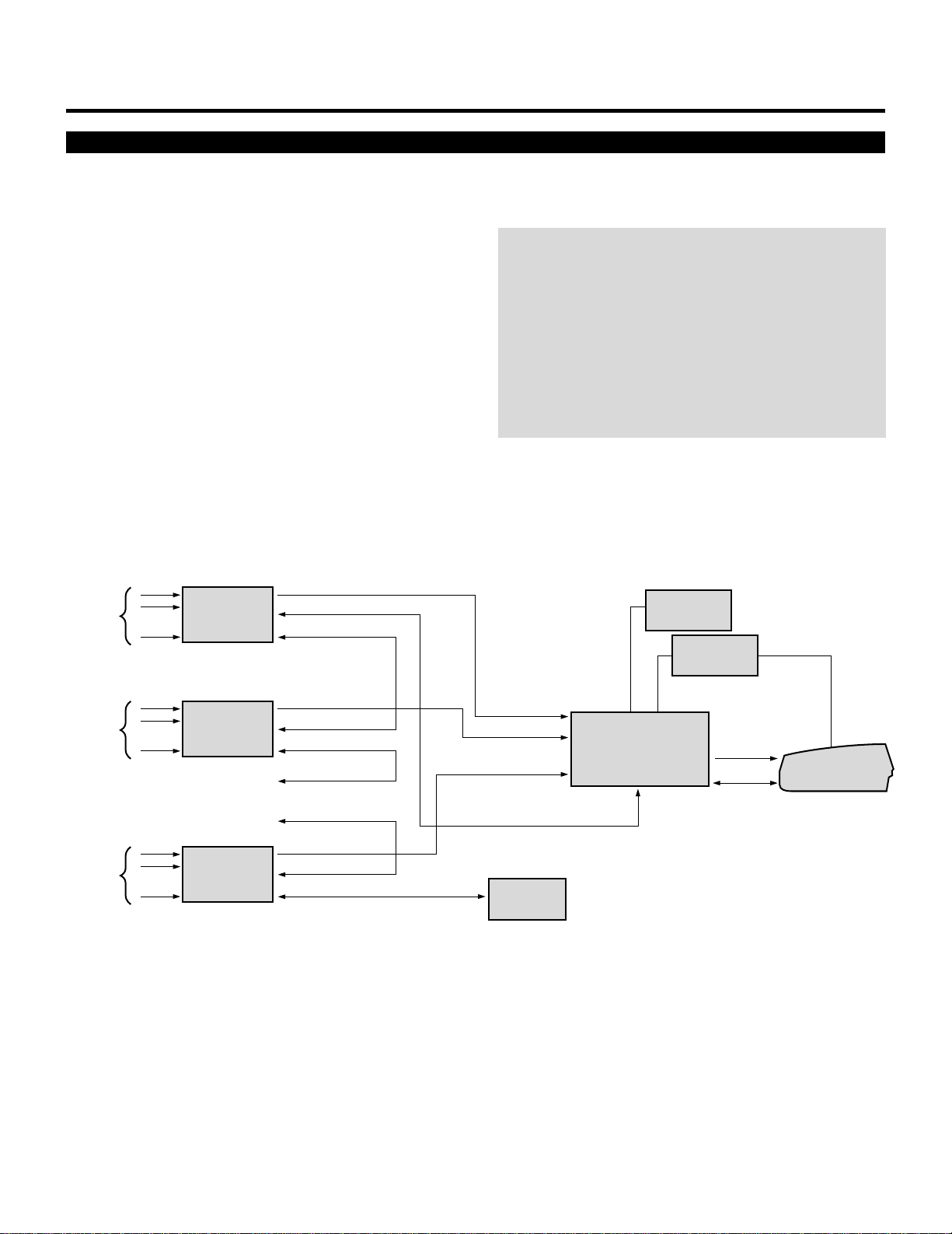
When Used with Two Switchers or More (100 Inputs)
Up to 100 inputs can be accepted using the Switcher.
How to make connections:
SLAVE 1
• • • • • •
10 inputs
SLAVE 2
• • • • • •
10 inputs
SLAVE 10
• • • • • •
10 inputs
SLAVE 3
SLAVE 9
• • • • • • • • • • • • • • • • • • • •
Signal SWITCHER
Signal
OPTION (PC)
REMOTE
CONTROL
REMOTE 1
REMOTE 2
Signal
REMOTE 1
REMOTE 2
REMOTE 1
REMOTE 2
Signal
REMOTE 1
REMOTE 2
To SLOT 1
To SLOT 2
To SLOT 10
Signal
REMOTE 1
MASTER
SWITCHER
To REMOTE 2
REMOTE 1
OPTION
(PC)
PROJECTOR
1 Connect the REMOTE 1 terminal of the master Switcher
to the REMOTE 1 of the projector using the optional
control cable (15p-15p/CTL-6010).
2 First connect the REMOTE 2 terminal of the master
Switcher to the REMOTE 1 terminal of the first slave
Switcher using the same optional control cable as men-
tioned above. Second connect the REMOTE 2 terminal of
the first slave to the REMOTE 1 of the second slave, and
the REMOTE 2 terminal of the second slave to the
REMOTE 1 terminal of the third slave (— and the
REMOTE 2 of the ninth slave to the REMOTE 1 of the
tenth slave). Connect all the Switchers with optional
control cables.
• Make sure that the SW2 LEVEL mode is selected from the CONNECT CONDITION menu. Contact your dealer for the informa-
tion in detail.
• Refer to the user’s manual accompanying the Switcher.
• Cables mentioned are not included with the projector.
NOTE:
• Be sure to set all the Slide switches (S8603) of the
Switcher to RS-422 positions. Set the one on the last slave
Switcher to the appropriate position to match the con-
nected equipment such as a personal computer. (RS-422/
RS-232C for PC control of projector)
• Set the DIP switch S8601 of the Switcher.
• This operation does not work with the NEC GP-3000/GP-
3000G and the GP-5000/GP-5000G projectors.
13
EXAMPLES OF CONNECTIONS
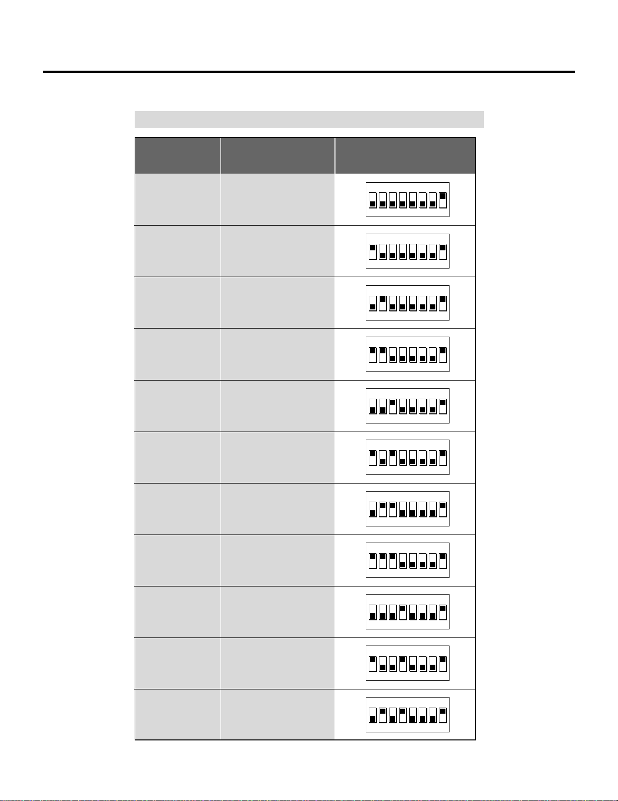
Set the DIP switch (S8601) of the Switcher as follows:
The Projector
Slot 1 of the Master
Slot 2 of the Master
Slot 3 of the Master
Slot 4 of the Master
Slot 5 of the Master
Slot 6 of the Master
Slot 7 of the Master
Slot 8 of the Master
Slot 9 of the Master
Slot 10 of the Master
Master
Slave 1
Slave 2
Slave 3
Slave 4
Slave 5
Slave 6
Slave 7
Slave 8
Slave 9
Slave 10
1 2 3 4 5 6 7 8
OPEN
1 2 3 4 5 6 7 8
OPEN
1 2 3 4 5 6 7 8
OPEN
1 2 3 4 5 6 7 8
OPEN
1 2 3 4 5 6 7 8
OPEN
1 2 3 4 5 6 7 8
OPEN
1 2 3 4 5 6 7 8
OPEN
1 2 3 4 5 6 7 8
OPEN
1 2 3 4 5 6 7 8
OPEN
1 2 3 4 5 6 7 8
OPEN
1 2 3 4 5 6 7 8
OPEN
ISS-6010
ISS-6010G
Output to
Setting of S8601
NOTE: Slave numbers 1 to 10 must correspond to the master’s slot numbers 1 to 10.
14
EXAMPLES OF CONNECTIONS
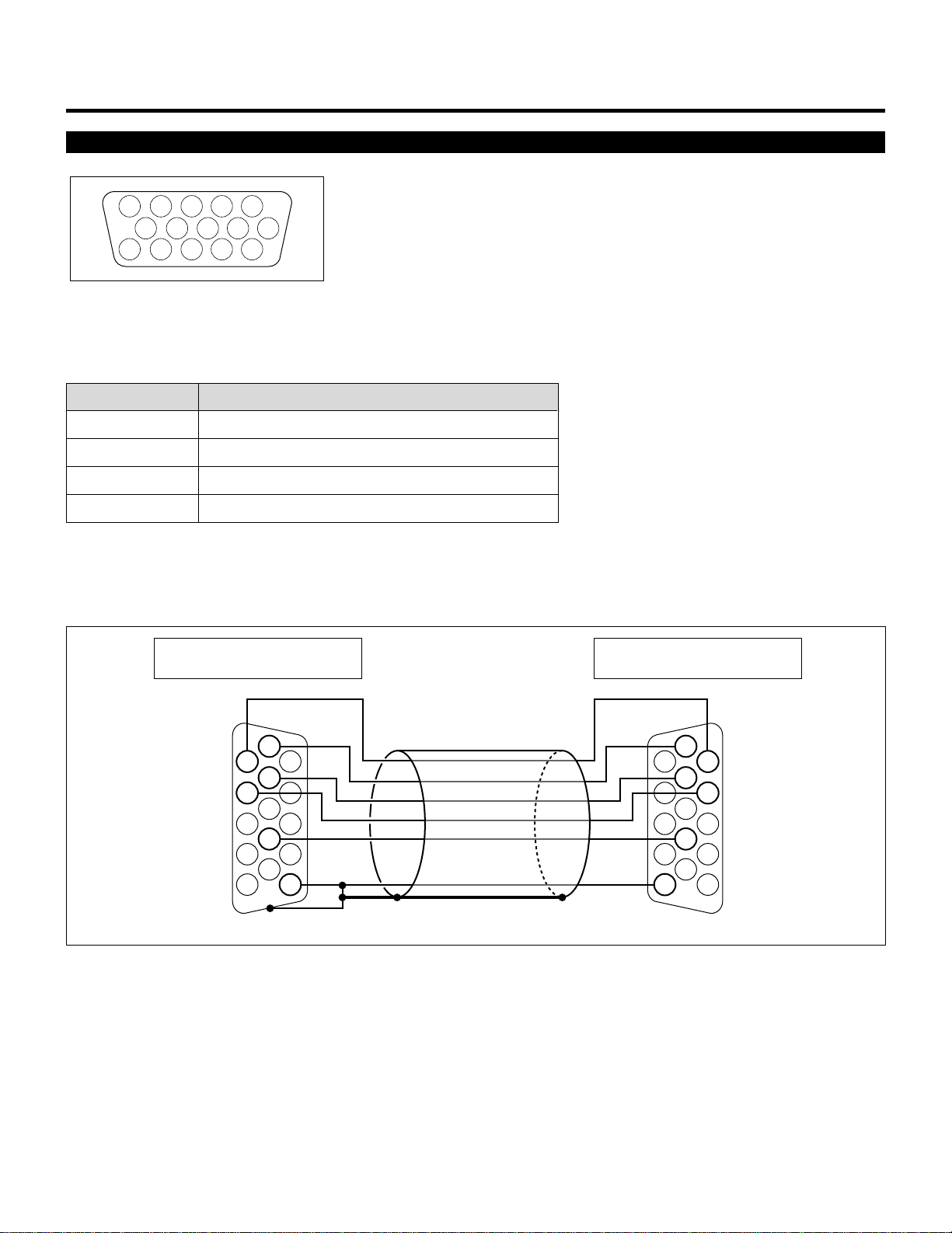
REMOTE 1 Terminal
12345
109876
1112131415
This terminal is used for either connecting the ISS-6010/ISS-6010G Switcher or a third party external control device. When the
Switcher is used, connect it with the optional control cable (15-15 pin; 50 ft./16m; CTL-6010) to this terminal.
When used with the Switcher.
Pin No. FUNCTION
1, 2, 6 and 7 Sending and receiving data when the Switcher is used.
3, 8, 11 and 12 Used inside the Projector. Normally set to OPEN.
9 Identifying the Projector
15 Ground
When using with the Switcher ISS-6010/ISS-6010G, connect no. 1,2,6,7,9 and15 pins of the projector to the same no. pins of the
switcher as shown below.
1
2
15
6
7
9
1
2
15
6
7
9
REMOTE 1 terminal of the Switcher
mini D-sub 15 pin (male)
REMOTE 1 terminal of the Projector
mini D-sub 15 pin (male)
Shield (frame ground)
Pins without a number are open.

15
EXAMPLES OF CONNECTIONS
When used in stand alone operation.
Pin No. SHORT/OPEN FUNCTION
14 SHORT External control mode ON
OPEN External control mode OFF
5 SHORT POWER ON
OPEN POWER OFF
10 SHORT PICTURE MUTE ON
OPEN PICTURE MUTE OFF
4 SHORT VIDEO
OPEN RGB
The term “SHORT” means to connect with pin 15
• When in the external control mode, the POWER, INPUT and PICTURE MUTE buttons on the remote control will not function.
NOTE: Pin 13 is the external remote signal terminal. The projector can be controlled by the same format signal as the supplied
remote control from the external controller regardless of setting Pin 14.
NOTE: When turning the power on using the external control, short Pin 5 about three seconds after supplying the AC power to the
projector; when turning the power off using the external control, power off the AC supply to the projector about three seconds after
opening Pin 5. These procedures are to protect your projector and the connected equipment.
4
123456
12345
6
12345
6
12345
6
12345
6
123456
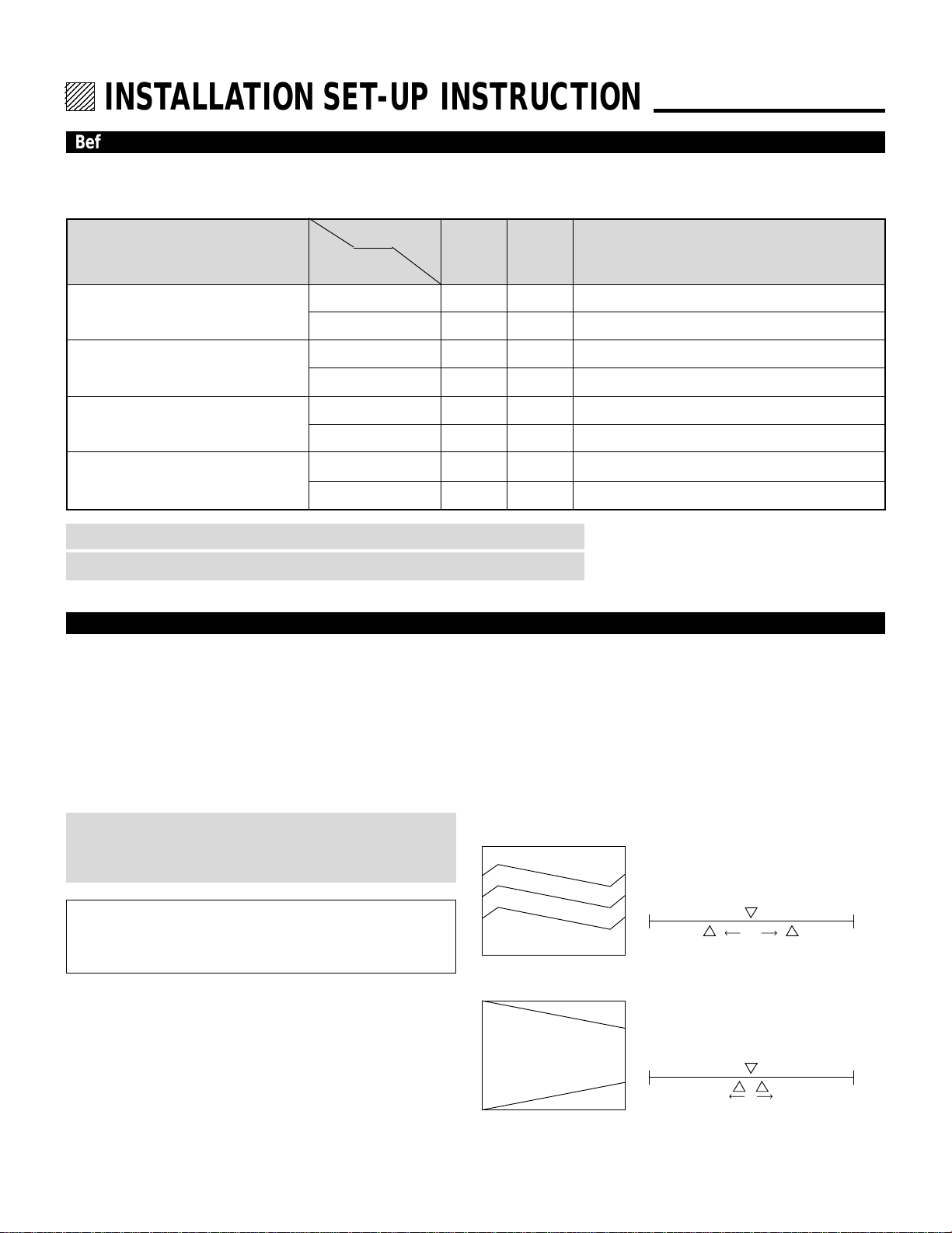
INSTALLATION SET-UP INSTRUCTION.
Before Installation
The installation procedure is different according to the projection system and screen size.
Installation and preliminary adjustments are required as shown on table below.
Adjustment
items
Screen size
(diagonal)
Projection type
None (
Set the focus ring when changing projection angle
)
Yes
None (
Set the focus ring when changing projection angle
)
Yes
None (S
et the focus ring when changing projection angle
)
Yes
None (
Set the focus ring when changing projection angle
)
Yes
None
Yes
Yes
Yes
Yes
Yes
Yes
Yes
100 inch
other than 100 inch
100 inch
other than 100 inch
100 inch
other than 100 inch
100 inch
other than 100 inch
Ceiling mounting Front projection
Desk top Front projection type
Ceiling mounting/Rear projection
Desk top Rear projection
None
None
Yes
Yes
Yes
Yes
Yes
Yes
Various
adjustments
Decorative lens panel, focus ring and CRT angle
change
NOTE: The “100 inch”covers the range of screen size between 91 and 130 inches.
NOTE: Knob adjustment on page 13.
Polarity change
Note on Installation
CAUTION ON INSTALLATION
Position the projector according to the procedures specified in
the following pages. Be sure to maintain the correct projection
distance, direction and angle for optimum performance.
Deviating from the correct installation could degrade the
performance of the projector and may cause reliability
problems.
WARNING
Static displays that are left on for extended periods may
cause CRT burns that are not covered under warranty.
For screen sizes other than 100", 200", and 300" diagonal,
adjust the CRT angle using the threaded holes marked “60-
300”. See page 14 for detailed procedures.
CAUTION ON ALIGNMENT ADJUSTMENT
The adjustment value of the items on the right must be within
the recommended range of the values on the right. If it is hard
or impossible to adjust the items on the right within the
recommended range of values, the most probable cause of this
is incorrect position of the projector. Check for correct
projection distance, direction and angle, and reposition as
recommended in this manual.
H
V
-100% +100%
within 550%
within 510%
H
V
-100% +100%
Value Recommendation
• TILT
• V-BOW within 550%
• H-BOW within 550%
• V-KEY
5
INSTALLATION SET-UP INSTRUCTION
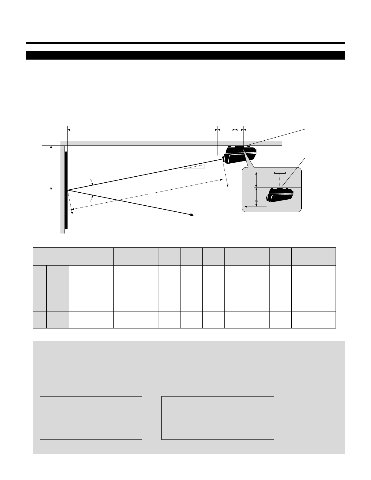
Projection Distance and Screen size for Ceiling Mount
•
Install in such a way that the projector and screen are positioned in the proper direction and at the proper angle. If not, the projector's
performance will be affected and its reliability will decrease. Be sure to position the projector properly.
The manufacture will not be held responsible for any problems occurring when the projector is not installed in the proper position.
The following shows the proper relative positions of the projector and screen. Refer to the table to determine the position of
installation.
When using a screen 150"
(3810mm) or larger (in the
diagonal direction)
E
B
Screen center
Ceiling Mounting
12°
Line of sight
12°
12°
A
Screen center
B
C
Ceiling Mounting
7.92"
(201mm)
5.12"
(130mm)
Ceiling Mount System
NOTE:
• For screen 150 inches (3810mm) or larger (in the diagonal direction), set so that the distance between the surface of installa-
tion of the mounting A and the ceiling is E.
• Set the projection distance based on the width of the screen.
• If the figures on the table do not match the figures in the formulae, use the figures on the table.
• For screen sizes of 60 to 300 inches not indicated on the table, use the following proportional formulae.
Units=mm W"=Screen H-Width
A = [(5/182W"112.5)2126.64]`1785
B = (0.2082A)`255
C = 0.9792A
E = (1/22Screen Height)1B
Units=inches W"=Screen H-Width
A = [(5/182W"112.5)24.99]`70.28
B = (0.2082A)`10.04
C = 0.9792A
E = (1/22Screen Height)1B
• The margin of error for projection distance (A) is53%
A
B
C
E
48"
(60")
Screen size H-Width
(4:3 Diagonal)
56"
(70")
64"
(80")
72"
(90")
80"
(100")
96"
(120")
118.75
3016
34.73
882
116.16
2951
–
–
85.51
2172
27.82
707
83.65
2125
–
–
96.59
2453
30.13
765
94.48
2400
–
–
107.68
2735
32.43
824
105.33
2676
–
–
140.91
3579
39.34
1000
137.86
3502
–
–
74.41
1890
25.51
648
72.79
1849
–
–
inch
mm
inch
mm
inch
mm
inch
mm
120"
(150")
144"
(180")
160"
(200")
192"
(240")
216"
(270")
240"
(300")
174.15
4423
46.25
1175
170.35
4327
–
–
207.40
5268
53.16
1351
202.87
5153
0.84
22
229.55
5830
57.77
1468
224.53
5704
2.24
57
273.86
6956
66.98
1702
267.88
6804
5.03
128
307.10
7800
73.89
1877
300.40
7630
7.11
181
340.36
8645
80.81
2053
332.92
8457
9.2
234
6
INSTALLATION SET-UP INSTRUCTION
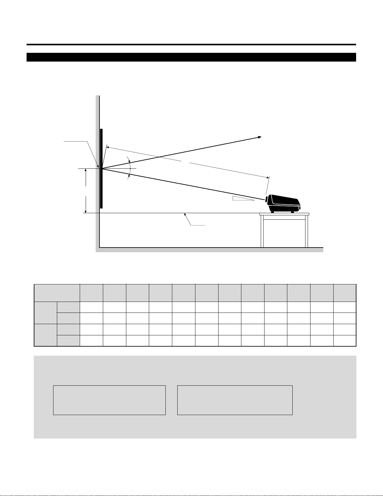
A:Distance between the lens and the screen center
D:Distance between the desk top and the screen center
Projection Distance and Screen Size for Desk Top
• The following shows the relative position relationship of the projector with the screen. See table below.
74.41
1890
23.94
608
85.51
2172
26.25
667
96.59
2453
28.55
725
107.68
2735
30.86
784
118.75
3016
33.16
842
140.91
3579
37.77
960
174.15
4423
44.68
1135
207.40
5268
51.59
1311
229.55
5830
56.19
1428
A
D
48"
(60")
Screen size H-Width
(4:3 Diagonal)
56"
(70")
64"
(80")
72"
(90")
80"
(100")
96"
(120")
120"
(150")
144"
(180")
160"
(200")
192"
(240")
216"
(270")
240"
(300")
NOTE:
• The projection distance is based on the screen width.
• Sizes not found between 48 (60) and 240 (300) inches are determined by the following formula.
Units=inches W"=Screen H-Width Units=mm W"=Screen H-Width
A = [(5/182W"112.5)24.99]`70.28 A = [(5/182W"112.5)2126.64]`1785
D = (0.2082A)`8.47 D = (0.2082A)`215
• When changing from ceiling mounting to desk top use, turn over the plate with the NEC trademark in the rear of the top cover.
Push the catch from the inside and remove the plate. Install it in the opposite manner.
inch
mm
inch
mm
273.86
6956
65.41
1662
307.10
7800
72.32
1837
340.36
8645
79.23
2013
Screen center
D
12°
12°
12°
Desk top line
A
Line of sight
Desk Top System
7
INSTALLATION SET-UP INSTRUCTION
inch
mm
74.41
1890
85.51
2172
96.59
2453
107.68
2735
118.75
3016
140.91
3579
174.15
4423
207.40
5268
229.55
5830
273.86
6956
307.10
7800
A
48"
(60")
Screen size H-Width
(4:3 Diagonal)
56"
(70")
64"
(80")
72"
(90")
80"
(100")
96"
(120")
120"
(150")
144"
(180")
160"
(200")
192"
(240")
216"
(270")
240"
(300")
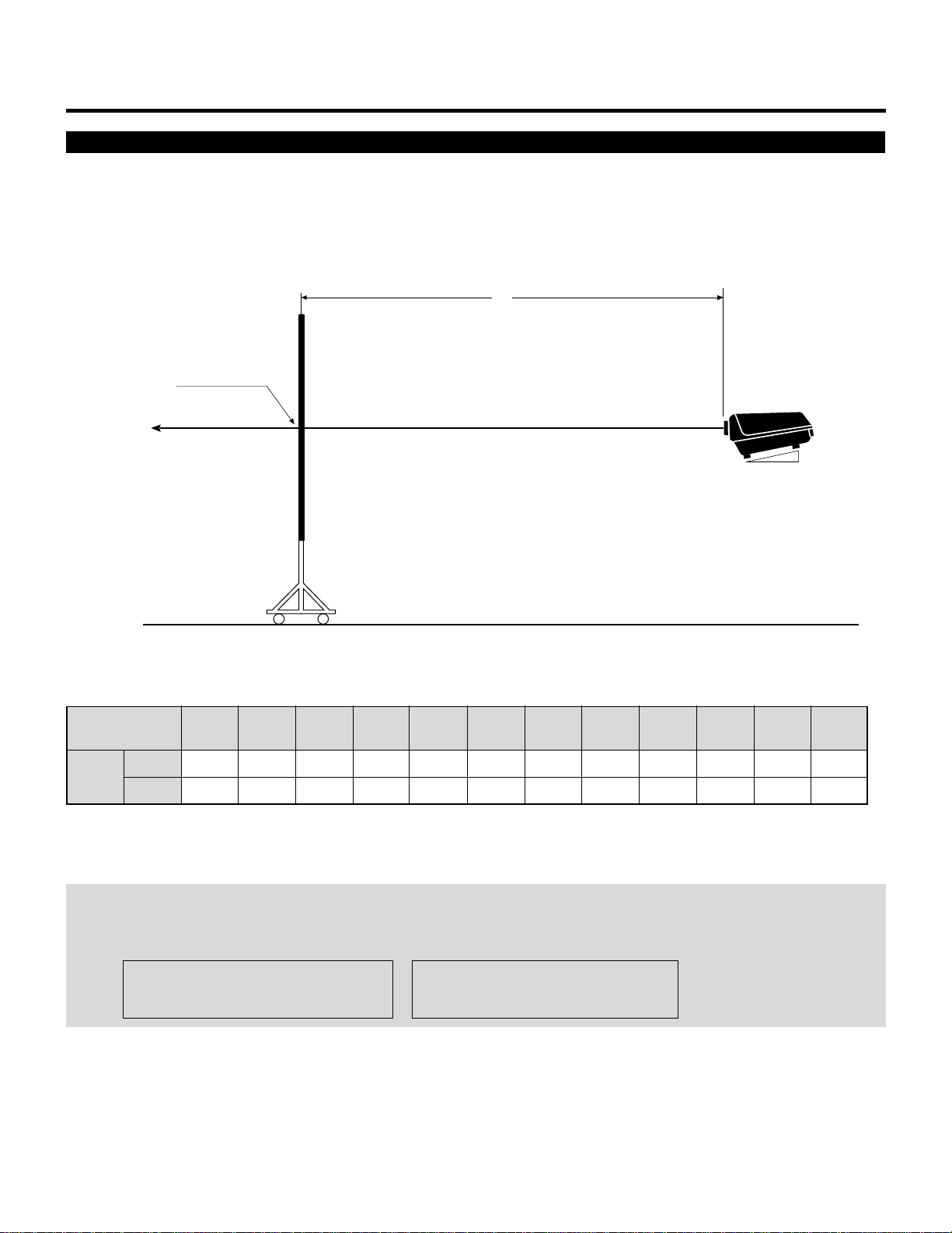
Projection Distance and Screen Size for Rear Projection
The following shows the relative position relationship of the projector with the screen.
See table below.
A:Distance between the lens and the screen center
NOTE:
• The projection distance is based on the screen width.
• Sizes not found between 48(60)and 240(300)inches are determined by the following formula.
Units=inches W"=Screen H-Width Units=mm W"=Screen H-Width
A = [(5/182W"112.5)24.99]270.28 A= [(5/182W"112.5)2126.64]21785
Rear Projection System
340.36
8645
Screen center
A
12°
12
123456
12345
6
12345
6
12345
6
12345
6
12345
6
123456
BEFORE SET-UP.
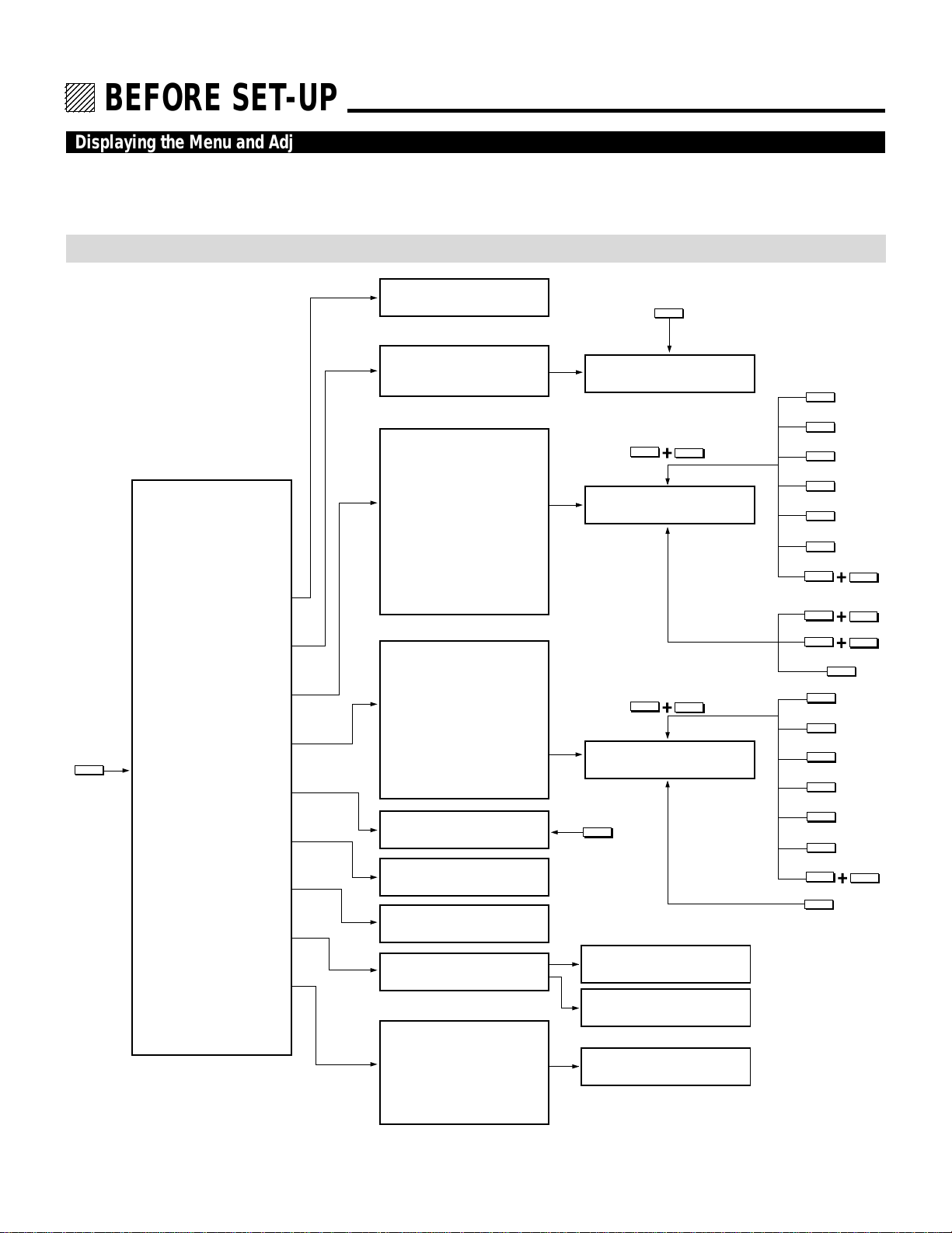
Displaying the Menu and Adjustment Screens
Access of all set-up functions is done through the menu system.
Depending upon button selection, your desired screen will be displayed as shown below:
ADJUST menu
NOTE: The examples here show the screen display when the projector is used with the NEC ISS-6010/ISS-6010G modular switcher.
• The R, G, B Gain item is not
included in the stand alone
adjust menu.
• The ADJUST, FOCUS, POINT and KELVIN buttons are on the Full Function remote control only.
ADJUST
ADJUST menu
– ADJUST –
1 / SIGNAL ENTRY
2 / FOCUS
3 / ALIGNMENT
4 / CONVERGENCE
5 / WHITE BAL
6 / R,G,B GAIN
7 / HOUR METER
8 / PASSCODE
9 / OPTION
SIGNAL ENTRY screen
FOCUS menu
– FOCUS –
1 / CENTER
2 / EDGE (ALL)
ALIGNMENT menu
– ALIGNMENT –
1 / TILT, SKEW
2 / BOW
3 / AMPLITUDE
4 / LINEARITY
5 / KEY-STONE
6 / PIN-CUSHION
7 / LINEAR-BAL
8 / KEY-BALANCE
9 / PIN-BALANCE
0 / PHASE
CONVERGENCE menu
– CONVERGENCE –
1 / TILT, SKEW
2 / BOW
3 / AMPLITUDE
4 / LINEARITY
5 / KEY-STONE
6 / PIN-CUSHION
7 / LINEAR-BAL
8 / POINT)
(
Adjustment screen
Adjustment screen
HOUR METER
screen
PASSCODE menu
OPTION menu
– OPTION –
1 / SETTING MODE
2 / MENU MODE
3 / SEQUENCER
4 / PJ ADDRESS
5 / VERSION
KELVIN
Adjustment screen
FOCUS
CTL
G
Adjustment screen
CTL
R,B
Adjustment screen
TILT
BOW
AMPLIT
LINEAR
KEYSTN
PINCUS
CTL
LINEAR
CTL
KEYSTN
CTL
PINCUS
PHASE
TILT
BOW
AMPLIT
LINEAR
KEYSTN
PINCUS
CTL
LINEAR
POINT
NEW PASSCODE?
input screen
PASSCODE
DISABLE? menu
Sub menu
/ Setting screen
13
Storing Projector Settings (Automatic Save Feature)
BEFORE SET-UP
You have two options to store projector settings in the memory:
automatically and manually.
mWhen the Automatic Save Feature mode is set to “ENABLE”,
projector settings will be stored in the projector’s memory
automatically.
Storing settings are done when any one of the following proce-
dures is performed:
• The END button is pressed several times to return the adjust-
ment screen to the source screen.
• One input is switched to another.
• The projector is turned off.
mWhen the Automatic Save Feature mode is set to “DISABLE”,
projector settings can be stored in the projector’s memory
manually.
If the current status is not stored due to pressing another button,
the “STORE ?” message is displayed. Use the CURSOR or
button to select either “YES” or “NO” and press the ENTER
button.
• If the adjustments have not been changed, the “STORE ?”
message is not displayed.
• To exit the mode without storing the current status, select
“NO”.
NOTE: The Automatic Save Feature mode has been set to
DISABLE by factory. To set to ENABLE, refer to the “Automatic
Save Feature” section on page 83.
STORE?
YES NO

14
BEFORE SET-UP
On ADJUST MODE
The ADJUST mode contains various adjustment items for set-up.
Open the ADJUST menu and select the item you wish to adjust. To
display the ADJUST menu, proceed as follows:
1 Press the ADJUST button.
• The projector may ask for your passcode.
2 Enter your registered passcode.
When a passcode has not been registered:
• Since no passcode is programmed at the factory, pressing the
ADJUST button will open the ADJUST menu.
• See “Entering Passcode”, “Registering Passcode”, “Changing
Your Passcode” and “Canceling Your Passcode” on pages 52
through 58.
When your passcode has already been registered:
• When finishing the ADJUST mode, the “RETURN USER
MODE?” menu will be displayed. If you select “YES” and
press ENTER to end the ADJUST mode, you will have to
enter your passcode to re-enter the ADJUST mode.
• When finishing the ADJUST mode by either selecting “NO”
or pressing END, you do not need to enter your passcode to
re-enter the ADJUST mode. To exit the ADJUST mode
temporarily during adjusting, select “NO”.
PASSCODE?
∗∗∗∗
15
BEFORE SET-UP
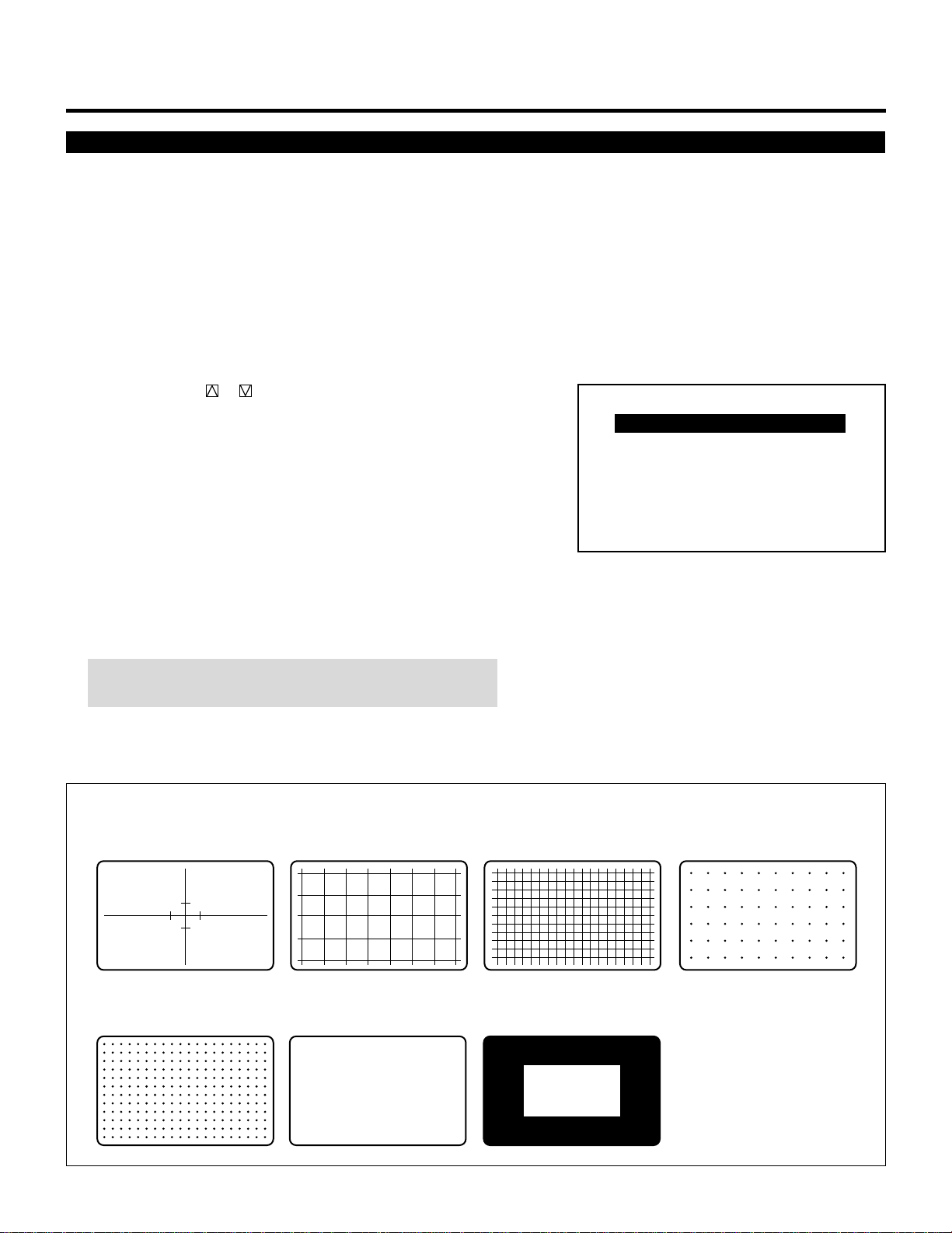
Test Pattern
This projector will generate a selection of test signals.
Seven kinds of internal test patterns can be selected from the TEST
PATTERN menu.
To display the TEST PATTERN menu, proceed as follows:
1 Press the TEST button on the Full function remote control.
• The “TEST PATTERN” menu will be displayed.
• When the END button is pressed, the “TEST PATTERN” menu
will disappear.
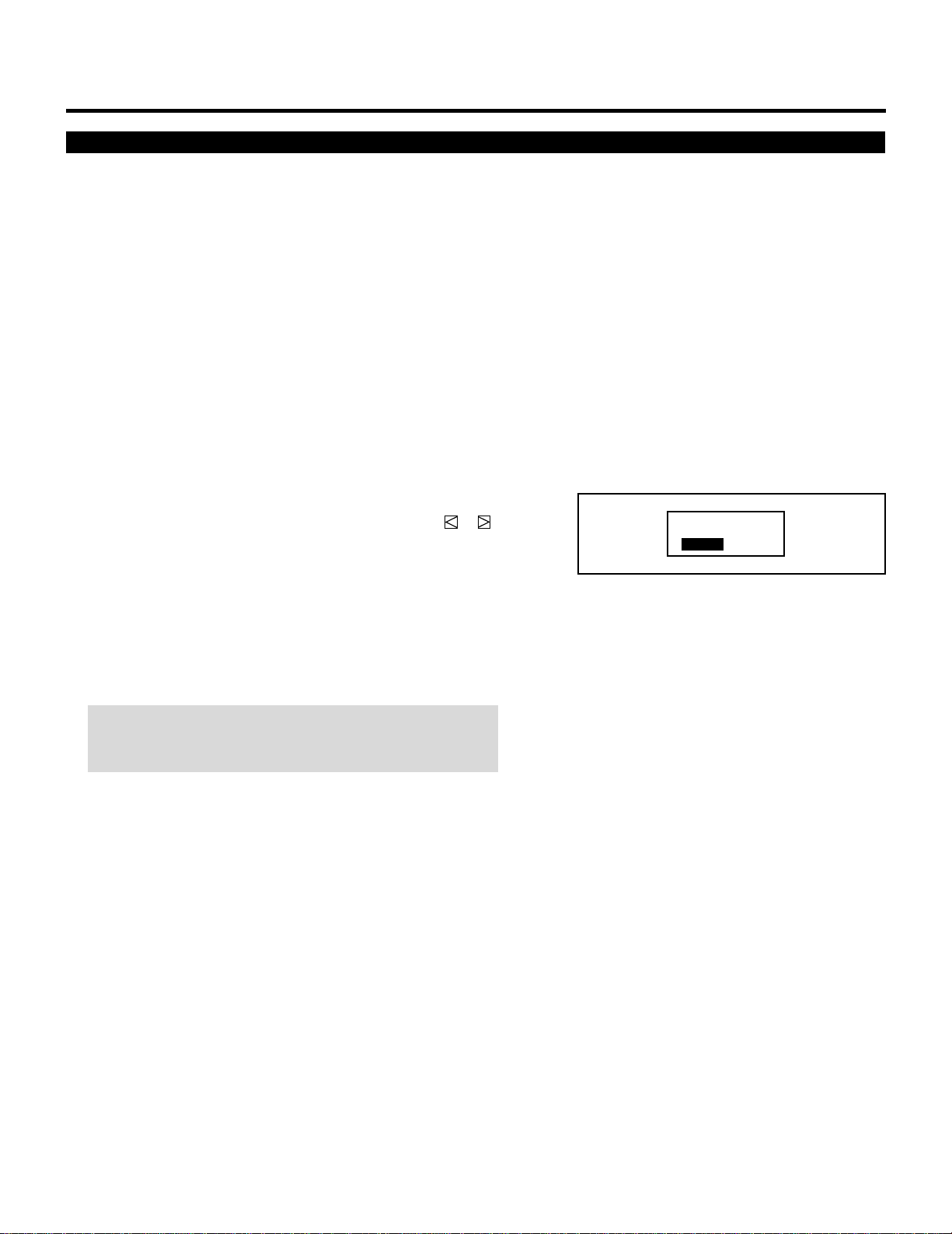
2 Use the CURSOR or button to highlight the test pattern you
wish to use and press ENTER.
• The selected test pattern will be displayed.
3 To return to the source screen, press the TEST and then the END
button.
• When the TEST button is pressed, the “TEST PATTERN”
menu will be displayed and when the END button is pressed,
the screen will be changed to the source screen.
• The projector will return to the original source screen by
pressing the END button only when no menu or no adjustment
screen is displayed.
NOTE: If there is no test pattern, the beams have been turned
off by the R, G, and B buttons on the remote control.
H H H H H H H H H H H H H H H H H H H H H H H H H H
H H H H H H H H H H H H H H H H H H H H H H H H H H
H H H H H H H H H H H H H H H H H H H H H H H H H H
H H H H H H H H H H H H H H H H H H H H H H H H H H
H H H H H H H H H H H H H H H H H H H H H H H H H H
H H H H H H H H H H H H H H H H H H H H H H H H H H
H H H H H H H H H H H H H H H H H H H H H H H H H H
H H H H H H H H H H H H H H H H H H H H H H H H H H
H H H H H H H H H H H H H H H H H H H H H H H H H H
H H H H H H H H H H H H H H H H H H H H H H H H H H
H H H H H H H H H H H H H H H H H H H H H H H H H H
H H H H H H H H H H H H H H H H H H H H H H H H H H
H H H H H H H H H H H H H H H H H H H H H H H H H H
H H H H H H H H H H H H H H H H H H H H H H H H H H
CROSS-HAIR
CROSS-COARSE CROSS-FINE DOT-COARSE
DOT-FINE
FOCUS WINDOW-WHITE
Adjustment test pattern
– TEST PATTERN –
CROSS-HAIR
CROSS-COARSE
CROSS-FINE
DOT-COARSE
DOT-FINE
FOCUS
WINDOW-WHITE
16
12345
6
12345
6
12345
6
12345
6
12345
6
123456
SIGNAL ENTRY.
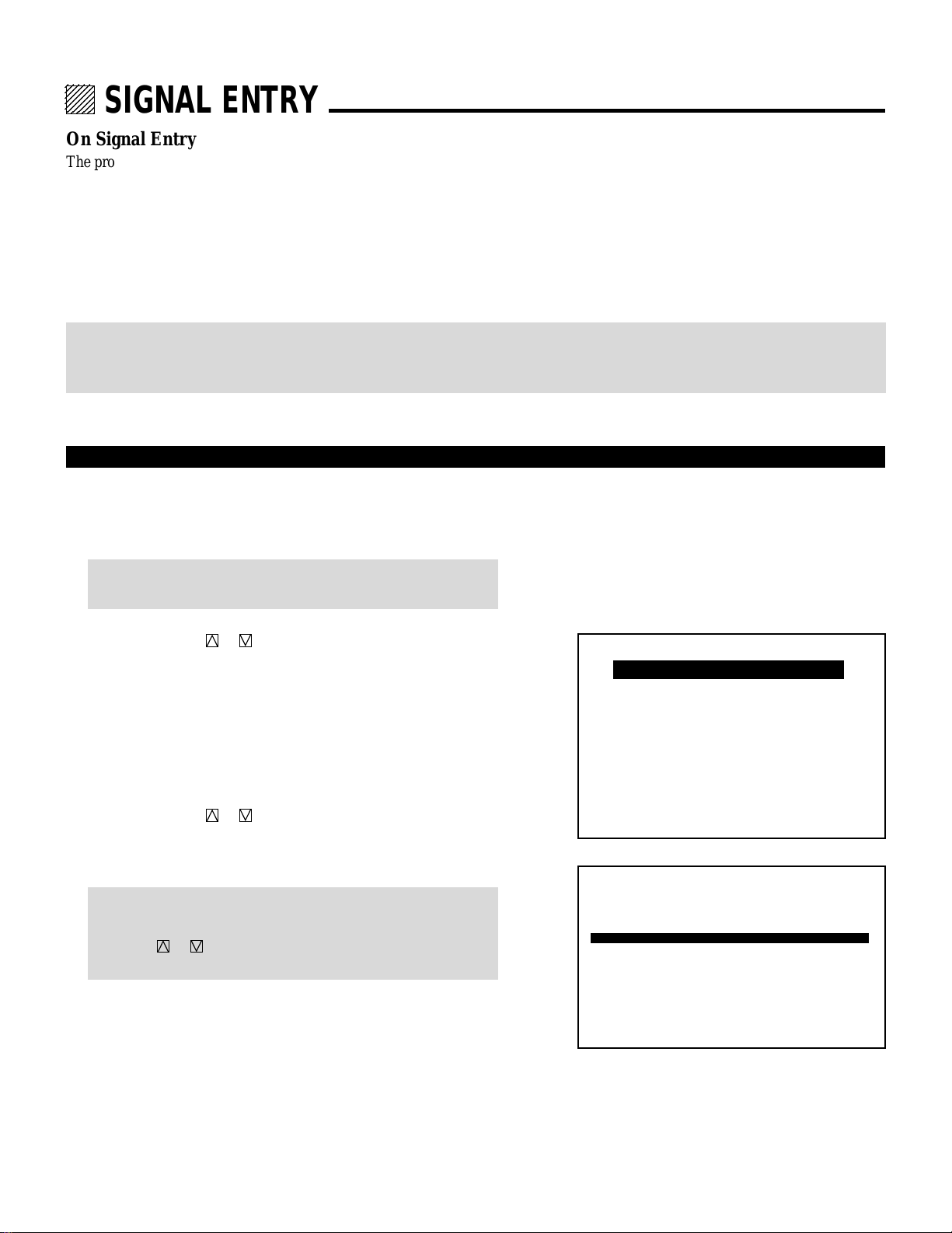
On Signal Entry
The projector uses a micro-processor to automatically read and distinguish between all video signals input at the same time. These
signals are then used to make optimum adjustments for focus, convergence, alignment, etc. Various parameters must be registered
into the micro-processor beforehand to ensure the video signals are recognized and adjusted to optimum quality.
The Signal Entry registers these video signals in the SIGNAL ENTRY list and at the same time obtains the various parameters
pertaining to these signals. Always access this mode first whenever inputting video signals for the first time so that you can register
the video signals before making any adjustments. If the current input signal(s) has not been registered, the “UNREGISTERED
SIGNAL” message is displayed on screen.
NOTE: If you have software which changes scanning mode due to the graphic board of your PC (such as VGA), it will be necessary
to register signal entry for each scanning mode. This can be done using your PC by way of stopping the software in each scanning
mode and performing a signal entry operation.
Signal Entry Procedures
To make the signal entry, proceed as follows:
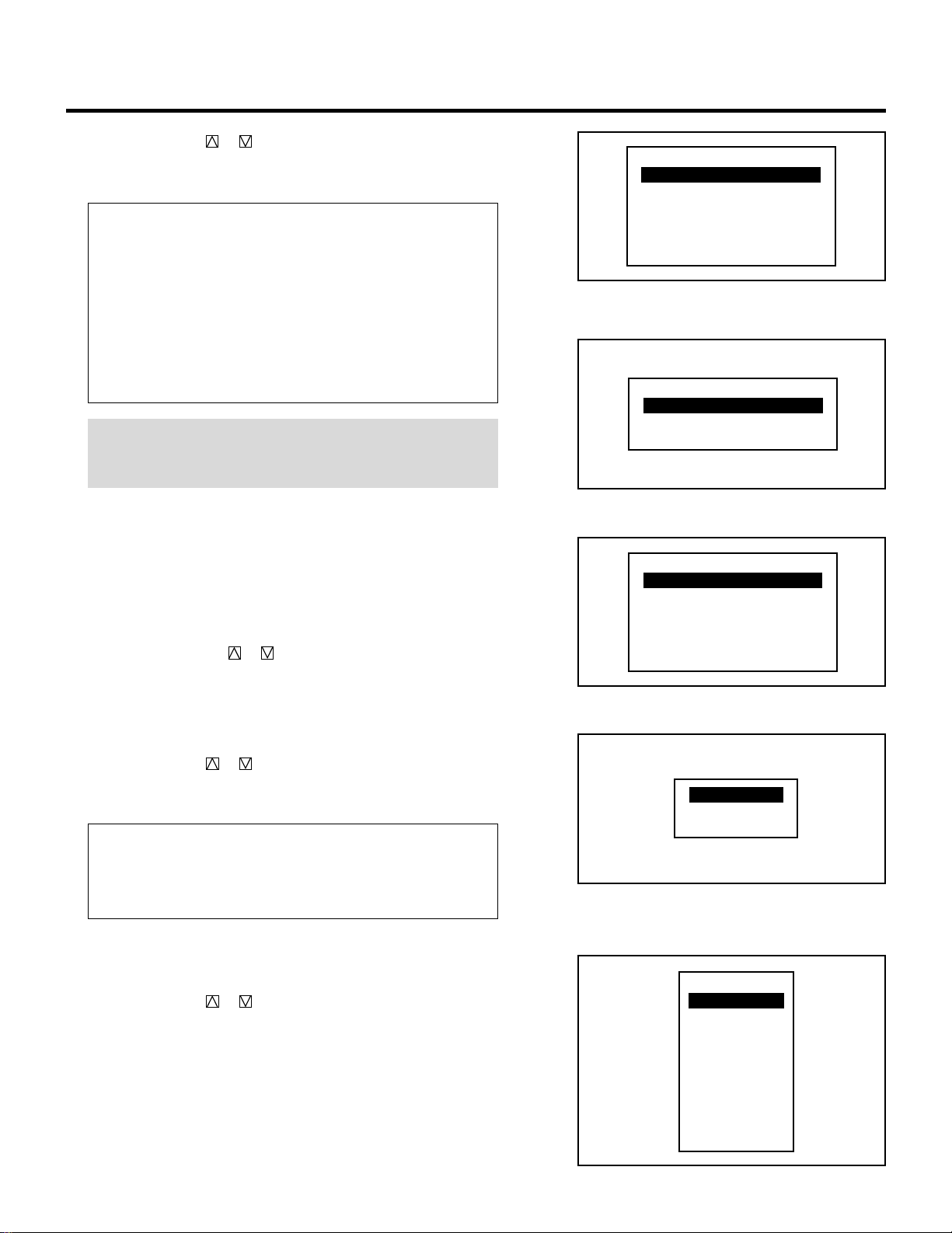
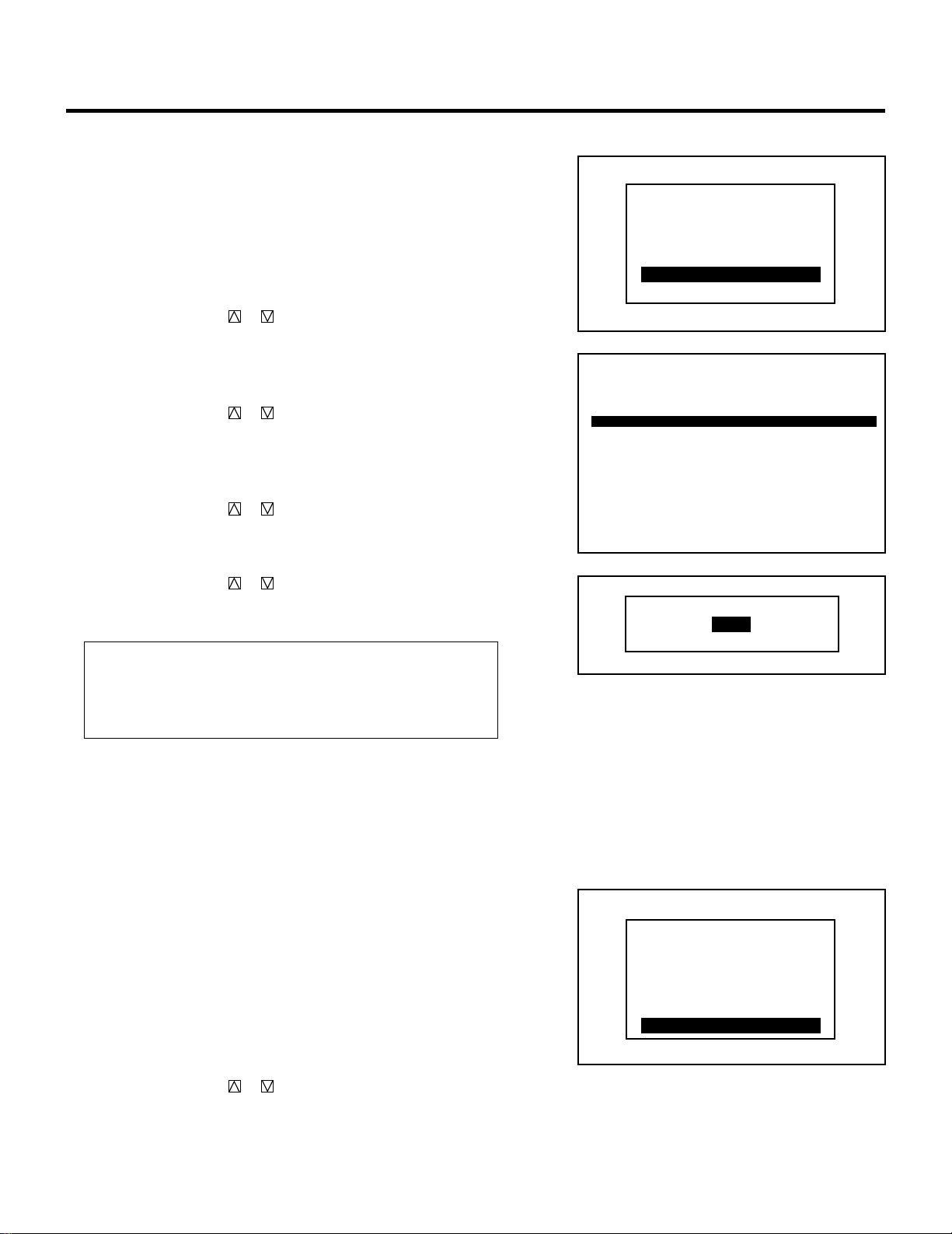
1 Press the ADJUST button.
• The “ADJUST” menu is displayed.
NOTE: The projector may ask you to enter your passcode. See
52 for the explanation of the PASSCODE.
2 Use the CURSOR or button to highlight the “1/SIGNAL
ENTRY” line and press ENTER.
• The “SIGNAL ENTRY” list will be displayed.
• You can also select the “SIGNAL ENTRY” list directly by
pressing the INPUT “1” button.
• When the projector is used in stand alone operation, the “6/R,
G, B GAIN” item is not included in the ADJUST menu.
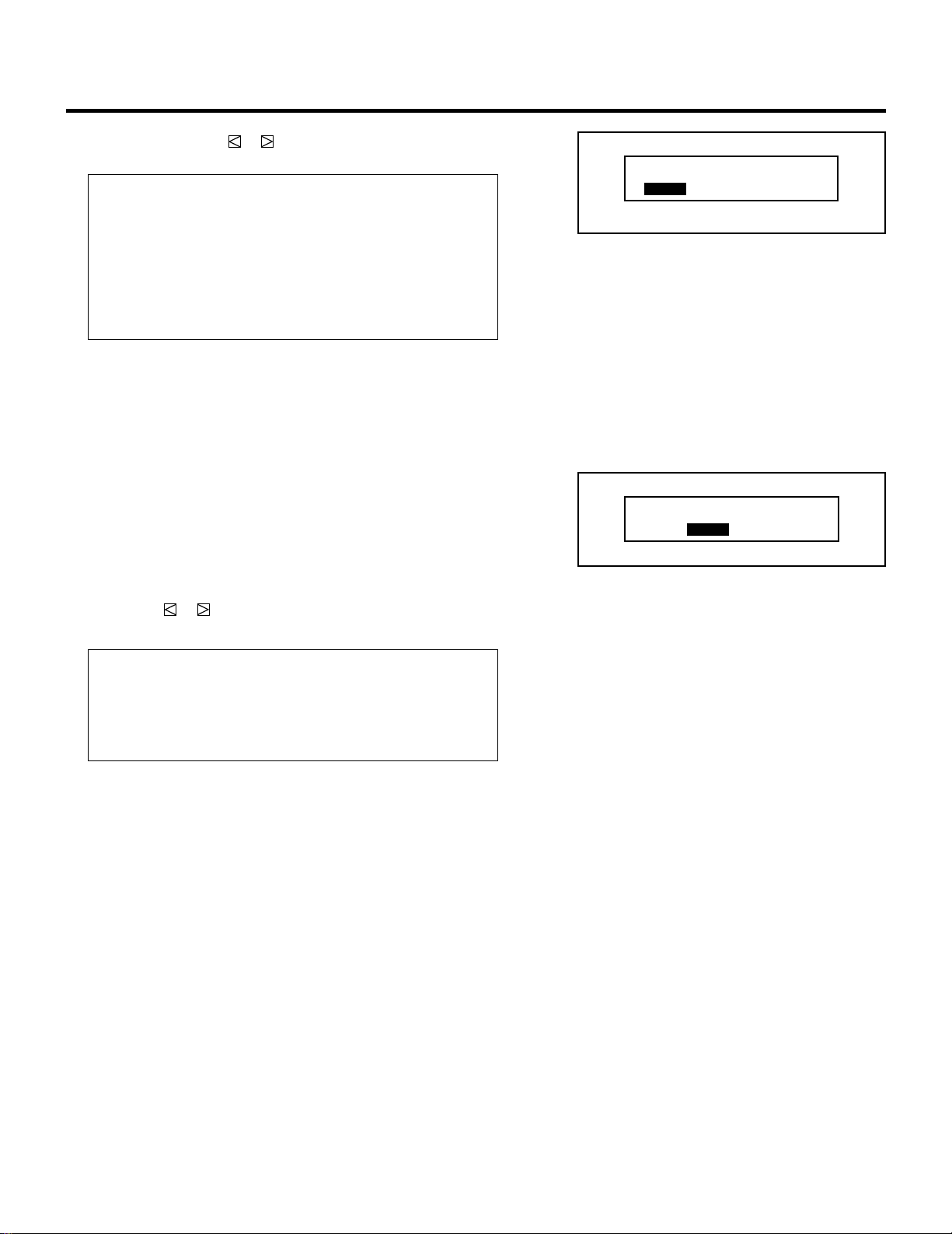
3 Use the CURSOR or button to select the desired line and
press ENTER.
• The Signal entry menu will be displayed.
NOTE: To advance to the next page or to the previous page,
hold down the CTL button then press the
CURSOR or button. To directly access a page, hold down
the CTL button then press any one of the INPUT buttons.
– ADJUST –
1 / SIGNAL ENTRY
2 / FOCUS
3 / ALIGNMENT
4 / CONVERGENCE
5 / WHITE BAL
6 / R,G,B GAIN
7 / HOUR METER
8 / PASSCODE
9 / OPTION
P01
ISS-6010 SW 2 LEVEL
NO INPUT NAME DATE
0 1 M – 01 S – 01 VTR – 1 12 / 01 / 92
0 2 M – 01 S – 02 VTR – 2 12 / 03 / 92
0 3 M – 01 S – 03 VIDEO-1 12 / 11 / 92
0 4 M – 01 S – 04 VTR – 3 12 / 24 / 92
0 5 M – 01 S – 05 RGB-1 12 / 25 / 92
06
07
08
09
10
SIGNAL ENTRY
17
SIGNAL ENTRY
4 Use the CURSOR or button to select the item and then press
ENTER.
• The Input terminal menu will be displayed.
Items to select
• NEW ENTRY........Registers a new signal.
• ENTRY COPY.......Copies any registered signal entry.
• ENTRY MOVE......Moves any registered signal entry.
• ENTRY DELETE ...Deletes any registered signal entry from
SIGNAL ENTRY.
• DATA COPY.........Copies gain data from any one of the
registered signals.
•
CHANGE DEFAULT
.Rewrites the data stored in DEFAULT AREA.
NOTE: When a vacant line is selected, the “SIGNAL ENTRY”
menu has three items only: “NEW ENTRY”, “ENTRY COPY” and
“ENTRY MOVE”.
m Selecting “NEW ENTRY”
When connecting a signal for the first time, you need to register
it into the projector’s memory. You can copy the initial setting
for the new signal from any other signal that has already been
registered or use the factory preset setting.
To do this, proceed as follows:
1) Use the CURSOR or button to select “NEW ENTRY”
and press ENTER.
• The Input terminal menu will be displayed.
When using the projector in stand alone application:
Use the CURSOR or button to select “VIDEO”, “RGB” or
“S-VIDEO”, and press ENTER.
• The “NAME INPUT” screen will be displayed.
Items to select
• VIDEO...... Selects the VIDEO input signal of this projector
• RGB......... Selects the RGB input signal of this projector
• S-VIDEO .. Selects the S-VIDEO input signal of this projector.
• Go on to Step 2).
When using with a single Switcher ISS-6010/ISS-6010G:
Use the CURSOR or button to select the input slot number
of the Switcher and press ENTER.
• Input slot numbers are from 1 through 10.
• The “NAME INPUT” screen will be displayed when you finish
entering the slot number.
• Go on to Step 2).
SIGNAL ENTRY
NEW ENTRY
ENTRY COPY
ENTRY MOVE
ENTRY DELETE
DATA COPY
CHANGE DEFAULT
SIGNAL ENTRY
NEW ENTRY
ENTRY COPY
ENTRY MOVE
SIGNAL ENTRY
NEW ENTRY
ENTRY COPY
ENTRY MOVE
ENTRY DELETE
DATA COPY
CHANGE DEFAULT
VIDEO
RGB
S-VIDEO
SLOT–01
SLOT–02
SLOT–03
SLOT–04
SLOT–05
SLOT–06
SLOT–07
SLOT–08
SLOT–09
SLOT–10
MASTER
18
When using with two or more ISS-6010/ISS-6010G switchers:
Use the CURSOR or button to select the input slot number
of the master Switcher and press ENTER. Then select the slot
number of the slave Switcher and press ENTER.
• The “MASTER” menu will be displayed when the slot number
of the master Switcher is selected.
• The “SLAVE” menu will be displayed when the slot number of
the slave Switcher is selected.
• Input slot numbers are from 1 through 10.
• The “NAME INPUT” screen will be displayed when you finish
entering the slot number.
• Go on to Step 2).
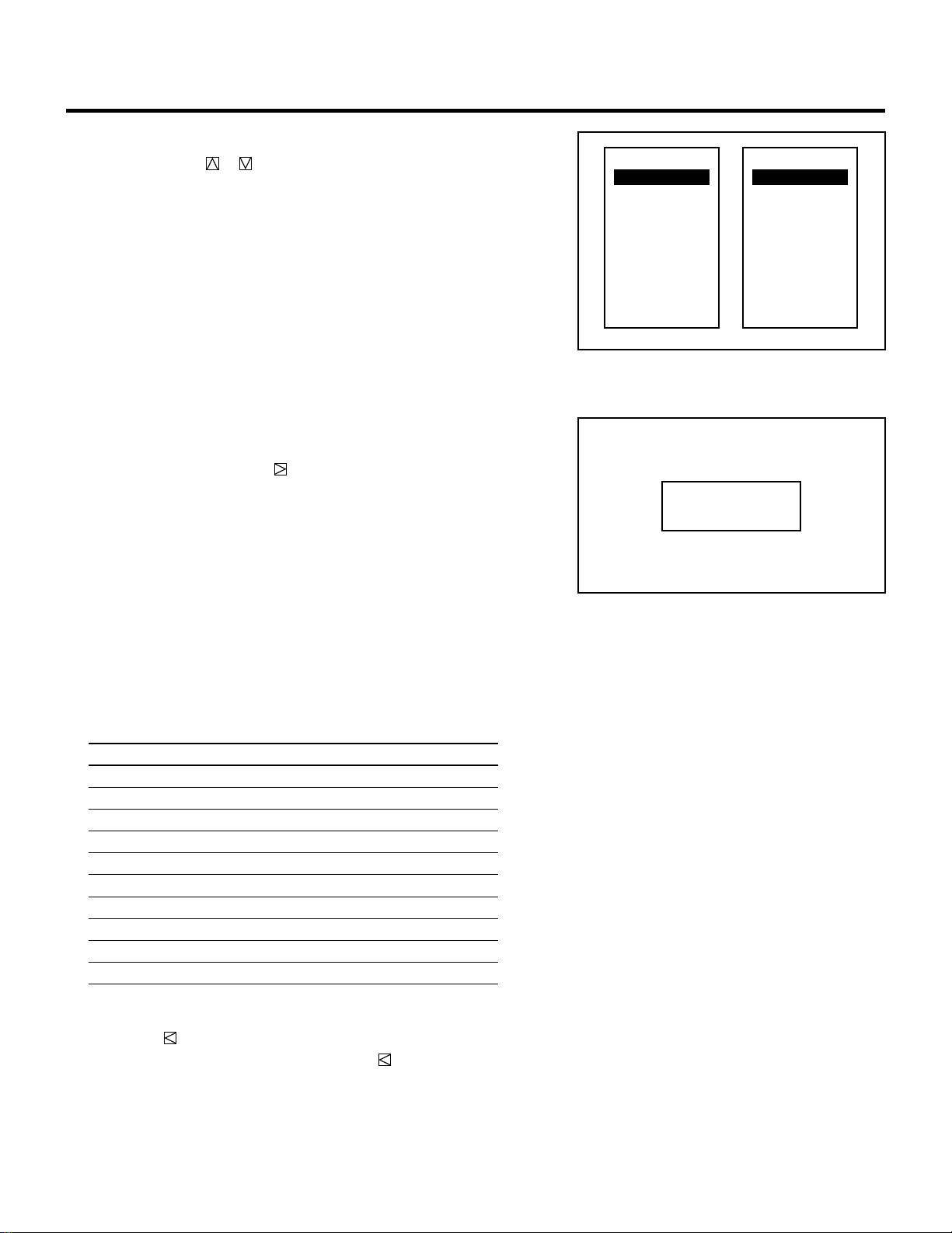
2) Input the source name by selecting one character at a time
with the INPUT buttons 1 through 10 and by moving the
cursor with the CURSOR button. After finishing the
selection of the characters, press ENTER.
• Up to eight characters can be selected.
• Eight characters are assigned to one INPUT button.
• Whenever the INPUT button is pressed, characters will be
rotated.
For example:
A → B → C → 1 → A .....
• When pressing the INPUT button while holding down the CTL
button, another group of characters will be rotated.
For example:
a → b → c → ! → a .....
• The characters corresponding to these INPUT buttons are as
follows:
When using With CTL
INPUT 1 A, B, C, and 1 a, b, c, and !
INPUT 2 D, E, F, and 2 d, e, f, and “
INPUT 3 G, H, I, and 3 g, h, i, and #
INPUT 4 J, K, L, and 4 j, k, l, and $
INPUT 5 M, N, O, and 5 m, n, o, and %
INPUT 6 P, Q, R, and 6 p, q, r, and &
INPUT 7 S, T, U, and 7 s, t, u, and ‘
INPUT 8 V, W, X, and 8 v, w, x, and (
INPUT 9 Y, Z, ?, and 9 y, z, /, and )
INPUT 10 *, ,, ., and 0 ;, :, +, and -
• If you have made an error in the input of a character, use the
CURSOR button and enter the correct letter or number.
To delete one character, move the CURSOR button to the
character to be deleted and then press the NORMAL button.
To delete all the entered name, hold down the CTL button then
press NORMAL.
• The “INITIAL DATA SELECT” menu will be displayed.
SIGNAL ENTRY
SLOT–01
SLOT–02
SLOT–03
SLOT–04
SLOT–05
SLOT–06
SLOT–07
SLOT–08
SLOT–09
SLOT–10
MASTER
SLOT–01
SLOT–02
SLOT–03
SLOT–04
SLOT–05
SLOT–06
SLOT–07
SLOT–08
SLOT–09
SLOT–10
SLAVE
––––––––
NAME INPUT
19
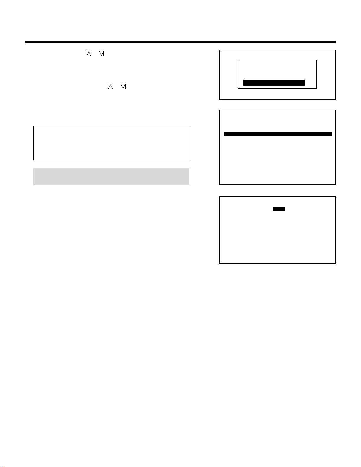
3) Use the CURSOR or button to select an item and press
ENTER.
• When selecting “ENTRY NUMBER”, the “DATA COPY
SELECT SOURCE” message will be displayed at the bottom of
the screen. Use the CURSOR or button to select the signal
you wish to copy the initial settings from and press ENTER.
• The “SOURCE INFORMATION” screen will be displayed.
• Pressing END will return to the “SIGNAL ENTRY” list. Go on
to Step 5.
Items to select
• DEFAULT.............Uses the data stored in the DEFAULT AREA
• TEMPORARY.......Uses the data which is currently displayed
•
ENTRY NUMBER
....Copies the data from the registered signal
NOTE: You can check and change various parameters on the
“SOURCE INFORMATION” menu. See page 24.
SIGNAL ENTRY
P01
DATA COPY SELECT SOURCE
ISS-6010 SW 2 LEVEL
NO INPUT NAME DATE
0 1 M – 01 S – 01 VTR – 1 12 / 01 / 90
0 2 M – 01 S – 02 VTR – 2 12 / 03 / 90
0 3 M – 01 S – 03 VIDEO-1 12 / 11 / 90
0 4 M – 01 S – 04 VTR – 3 12 / 24 / 90
0 5 M – 01 S – 05 RGB-1 12 / 25 / 90
0 6 M – 01 S – 06 VIDEO-2 12 / 30 / 90
0 7 M – 01 S – 07 VIDEO-3 12 / 31 / 90
0 8 M – 01 S – 08 NTSC 01 / 15 / 91
0 9 M – 01 S – 09 PA L 01 / 16 / 91
1 0 M – 01 S – 10 SECAM 01 / 29 / 91
SIGNAL ENTRY
SOURCE INFORMATION
M-01 S-01
FREQUENCY
∗∗∗∗∗∗∗∗
OFF
SYNC DETECT
AUTO COMP.
fh =
fv =
Khz
Hz
∗∗∗ ∗
∗∗ ∗
SYNC
ASTIG
DEFAULT
HD (`) VD (`)
VIDEO MODE
NTSC 3.58
COUNTER TIMER
∗∗∗∗∗ ∗∗
:
.
.
POSITION
WIDE
COLOR TEMP
6500 K
AKB
OFF
∗∗∗∗
FONT
NORMAL
LOCKNAME
DEFAULT
TEMPORARY
ENTRY NUMBER
INITIAL DATA SELECT
20
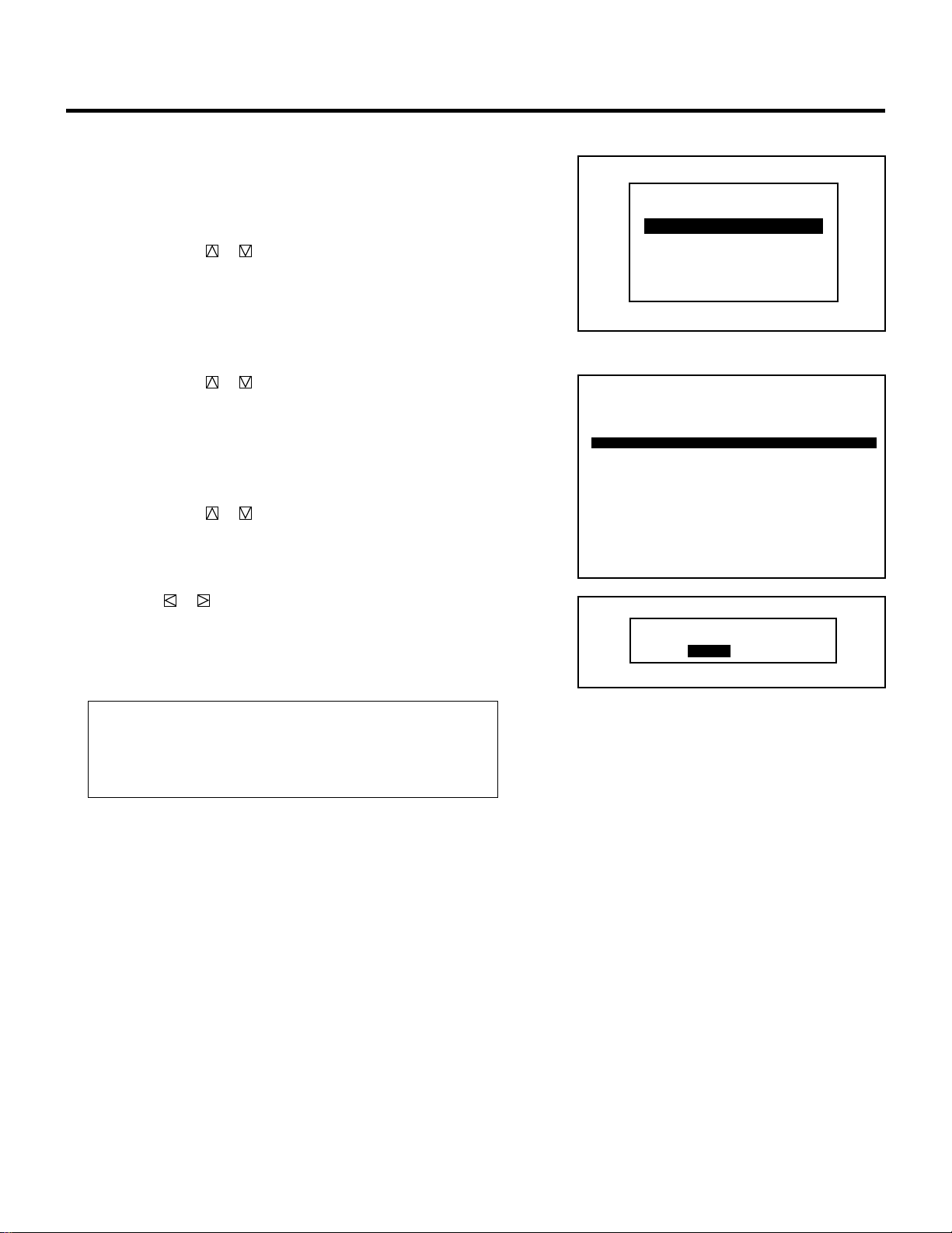
m When selecting “ENTRY COPY”
You can copy one of the registered input to the currently selected
line.
To do this, proceed as follows:
1) Use the CURSOR or button to select “ENTRY COPY” and
then press ENTER.
• The “ENTRY COPY SELECT SOURCE” message will be
displayed at the bottom of the screen.
2) Use the CURSOR or button to select a line you wish to
copy from and then press ENTER.
• The “ENTRY COPY SELECT DESTINATION” message will
be displayed at the bottom of the screen.
3) Use the CURSOR or button to select a line you wish to
copy to and press ENTER.
• When there is already a registered signal in the selected line, the
“ENTRY DATA OVERWRITE?” prompt is displayed. Use the
CURSOR or button to select “YES” or “NO” and then
press ENTER.
• When the “ENTRY COPY END” message is displayed, this
completes the ENTRY COPY mode.
•
The “SIGNAL ENTRY” list is displayed. Go on to Step
5.
Items to select
• YES ......... Overwrites the selected signal that has already
been registered.
• NO........... Stops overwriting.
SIGNAL ENTRY
SIGNAL ENTRY
NEW ENTRY
ENTRY COPY
ENTRY MOVE
ENTRY DELETE
DATA COPY
CHANGE DEFAULT
P01
ENTRY COPY SELECT SOURCE
ISS-6010 SW 2 LEVEL
NO INPUT NAME DATE
0 1 M – 01 S – 01 VTR – 1 12 / 01 / 90
0 2 M – 01 S – 02 VTR – 2 12 / 03 / 90
0 3 M – 01 S – 03 VIDEO-1 12 / 11 / 90
0 4 M – 01 S – 04 VTR – 3 12 / 24 / 90
0 5 M – 01 S – 05 RGB-1 12 / 25 / 90
0 6 M – 01 S – 06 VIDEO-2 12 / 30 / 90
0 7 M – 01 S – 07 VIDEO-3 12 / 31 / 90
0 8 M – 01 S – 08 NTSC 01 / 15 / 91
0 9 M – 01 S – 09 P A L 01 / 16 / 91
1 0 M – 01 S – 10 SECAM 01 / 29 / 91
SIGNAL ENTRY
ENTRY DATA OVERWRITE?
YES NO
21
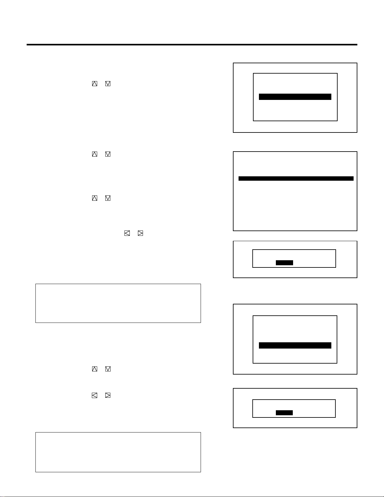
m When selecting “ENTRY MOVE”
You can move one of the registered inputs to the currently
selected line. To do this, proceed as follows:
1) Use the CURSOR or button to select “ENTRY MOVE”
and then press ENTER.
• The “ENTRY MOVE SELECT SOURCE” message will be
displayed at the bottom of the screen.
2) Use the CURSOR or button to select a line you wish to
move and then press ENTER.
• The “ENTRY MOVE SELECT DESTINATION” message
will be displayed at the bottom of the screen.
3) Use the CURSOR or button to select a line you wish to
move to and press ENTER.
• When there is already a registered signal in the selected
line, the “ENTRY DATA OVERWRITE?” prompt will be
displayed. Use the CURSOR or button to select
“YES” or “NO” and then press ENTER.
• When the “ENTRY MOVE END” message will be dis-
played, this completes the ENTRY MOVE mode.
• The “SIGNAL ENTRY” list will be displayed. Go on to
Step 5.
Items to select
• YES ......... Overwrites the selected signal that has already
been registered.
• NO........... Stops overwriting.
m When selecting “ENTRY DELETE”
You can delete one of the signals in the currently selected line .
To do this, proceed as follows:
1) Use the CURSOR or button to select “ENTRY DE-
LETE” and then press ENTER.
• The “SELECT LINE DELETE?” menu will be displayed.
2) Use the CURSOR or button to select either “YES” or
“NO” and then press ENTER.
• The “SIGNAL ENTRY” list will be displayed. Go on to
Step 5.
Items to select
• YES ......... Deletes the selected signal that has already been
registered.
• NO ........... Stops deleting.
SIGNAL ENTRY
SIGNAL ENTRY
NEW ENTRY
ENTRY COPY
ENTRY MOVE
ENTRY DELETE
DATA COPY
CHANGE DEFAULT
P01
ENTRY MOVE SELECT SOURCE
ISS-6010 SW 2 LEVEL
NO INPUT NAME DATE
0 1 M – 01 S – 01 VTR – 1 12 / 01 / 90
0 2 M – 01 S – 02 VTR – 2 12 / 03 / 90
0 3 M – 01 S – 03 VIDEO-1 12 / 11 / 90
0 4 M – 01 S – 04 VTR – 3 12 / 24 / 90
0 5 M – 01 S – 05 RGB-1 12 / 25 / 90
0 6 M – 01 S – 06 VIDEO-2 12 / 30 / 90
0 7 M – 01 S – 07 VIDEO-3 12 / 31 / 90
0 8 M – 01 S – 08 NTSC 01 / 15 / 91
0 9 M – 01 S – 09 PAL 01 / 16 / 91
1 0 M – 01 S – 10 SECAM 01 / 29 / 91
SIGNAL ENTRY
ENTRY DATA OVERWRITE?
YES NO
SELECT LINE DELETE?
YES NO
SIGNAL ENTRY
NEW ENTRY
ENTRY COPY
ENTRY MOVE
ENTRY DELETE
DATA COPY
CHANGE DEFAULT
22
SIGNAL ENTRY
m When selecting “DATA COPY”
To help assist in adjusting multiple inputs this projector has a
feature called DATA COPY. This feature allows you to copy the
memory data from one input to another input. By copying this
data from an input that has already been adjusted to an existing
input you will not have to do a complete adjustment.
To do this, proceed as follows:
1) Use the CURSOR or button to select “DATA COPY”
and then press ENTER.
• The “DATA COPY SELECT SOURCE” message will be
displayed at the bottom of the screen.
2) Use the CURSOR or button to select the signal to copy
from and then press ENTER.
• The “DATA COPY SELECT DESTINATION” message
will be displayed at the bottom of the screen.
3) Use the CURSOR or button to select the signal you wish
to copy to and press ENTER.
• The “INCLUDE PHASE DATA?” menu will be displayed.
4) Use the CURSOR or button to select either “NO” or
“YES” and press ENTER.
• Select “NO” in normal operation.
Items to select
• NO........... Copies the data which does not include the phase
data.
• YES ......... Copies the data which includes the phase data.
• When “GAIN DATA COPY END” message will be
displayed, this completes the DATA COPY mode.
• The “SIGNAL ENTRY” list will be displayed. Go on to
Step 5.
m When selecting “CHANGE DEFAULT”
All of the adjustment data of the selected signal will be stored in
the DEFAULT AREA.
The data stored in the DEFAULT AREA can be recalled by
pressing the NORMAL button.
Selecting “DEFAULT” from the “INITIAL DATA SELECT”
menu during signal entry will utilize the data stored in the
“DEFAULT AREA”.
To do this, proceed as follows:
1) Use the CURSOR or button to select “CHANGE
DEFAULT” and press ENTER.
• The “STORE TO DEFAULT AREA?” will be displayed.
P01
DATA COPY SELECT SOURCE
ISS-6010 SW 2 LEVEL
NO INPUT NAME DATE
0 1 M – 01 S – 01 VTR – 1 12 / 01 / 90
0 2 M – 01 S – 02 VTR – 2 12 / 03 / 90
0 3 M – 01 S – 03 VIDEO-1 12 / 11 / 90
0 4 M – 01 S – 04 VTR – 3 12 / 24 / 90
0 5 M – 01 S – 05 RGB-1 12 / 25 / 90
0 6 M – 01 S – 06 VIDEO-2 12 / 30 / 90
0 7 M – 01 S – 07 VIDEO-3 12 / 31 / 90
0 8 M – 01 S – 08 NTSC 01 / 15 / 91
0 9 M – 01 S – 09 P A L 01 / 16 / 91
1 0 M – 01 S – 10 SECAM 01 / 29 / 91
SIGNAL ENTRY
SIGNAL ENTRY
NEW ENTRY
ENTRY COPY
ENTRY MOVE
ENTRY DELETE
DATA COPY
CHANGE DEFAULT
INCLUDE PHASE DATA?
NO
YES
SIGNAL ENTRY
NEW ENTRY
ENTRY COPY
ENTRY MOVE
ENTRY DELETE
DATA COPY
CHANGE DEFAULT
23
SIGNAL ENTRY
2) Use the CURSOR or button to select an item and press
ENTER.
Items to select
• YES ......... The picture parameter data of the selected signal
will be stored in the DEFAULT AREA.
• NO........... The picture parameter data of the selected signal
will not be stored in the DEFAULT AREA.
• CANCEL... All cancelled information will be stored in the
DEFAULT AREA.
• If the “SIGNAL ENTRY” list will be displayed, this
completes the CHANGE DEFAULT mode.
• To end the “SIGNAL ENTRY” list, go on to Step 5.
5 To complete the signal entry, press the END button.
• Whenever the END button is pressed, the menus will sequence
in this order:
“ADJUST” menu → Source screen.
• When your passcode is in effect, the “RETURN USER
MODE?” screen will be displayed. If this happens, use the
CURSOR or button to select either “YES” or “NO” and
press ENTER.
Items to select
• YES ......... When you try to enter the ADJUST mode the next
time, you will need to re-enter your passcode.
• NO........... When you try to enter the ADJUST mode the next
time, you will not need to re-enter your passcode.
RETURN USER MODE?
YES NO
STORE TO DEFAULT AREA?
YES NO
CANCEL

24
SIGNAL ENTRY
Checking and Setting Various Parameters
Parameters of the signal currently projected can be displayed. To
view or change the parameters, proceed as follows:
1 Press the ADJUST button.
The “ADJUST” menu will be displayed.
NOTE: The projector may ask you to enter your passcode.
• See page 52 for Passcode explanation.
2 Press the INFO button.
• The “SOURCE INFORMATION” screen will be displayed.
• The “SOURCE INFORMATION” screen will be displayed also
when you exit the “SIGNAL ENTRY” screen.
3 Check and / or set the various parameters of the signal currently
projected.
The menu items you can set are NAME, LOCK ON/OFF, SYNC
DETECT, COLOR TEMP, AKB ON/OFF, COUNTER, TIMER,
POSITION, FONT, and ASTIG. See the following pages for an
explanation of each setting.
– ADJUST –
1 / SIGNAL ENTRY
2 / FOCUS
3 / ALIGNMENT
4 / CONVERGENCE
5 / WHITE BAL
6 / R,G,B GAIN
7 / HOUR METER
8 / PASSCODE
9 / OPTION
SOURCE INFORMATION
M-01 S-01
FREQUENCY
∗∗∗∗∗∗∗∗
OFF
SYNC DETECT
AUTO COMP.
fh =
fv =
Khz
Hz
∗∗∗ ∗
∗∗ ∗
SYNC
ASTIG
DEFAULT
HD (`) VD (`)
VIDEO MODE
NTSC 3.58
COUNTER TIMER
∗∗∗∗∗ ∗∗
:
.
.
POSITION
WIDE
COLOR TEMP
6500 K
AKB
OFF
∗∗∗∗
FONT
NORMAL
LOCKNAME

25
SIGNAL ENTRY
m Setting “NAME”
This function is used to change a user name that has previously
been entered.
To do this, proceed as follows:
1) Use the CURSOR buttons to select “NAME” and then press
ENTER.
• The “NAME INPUT” screen will be displayed.
2) Input a new source name by selecting one character at a time
with the INPUT buttons 1 through 10 and by moving the
cursor with the CURSOR button. Only after completely
finishing the selection of the characters, press ENTER.
• If you have made an error, use the CURSOR button and
reenter the correct letter or number.
To delete one character, move the under bar to the character
to be deleted and then press the NORMAL button.
To delete all the entered name, hold down the CTL button
then press the NORMAL button.
• The above is the same procedure of the signal entry. See
page 18 for more details.
• The screen will return to the “SOURCE INFORMATION”
screen.
m Setting “LOCK”
This function is used to stop the projector’s automatic signal
discrimination of various RGB signals.
Set the lock control to the ON position when connecting an
intermittent or low quality signal.
1) Use the CURSOR buttons to select “LOCK” and press
ENTER.
• The “LOCK CONTROL” menu will be displayed.
2) Use the CURSOR or button to select either “ON” or
“OFF” and press ENTER.
• The screen will return to the “SOURCE INFORMATION”
screen.
• Select “OFF” in normal operation.
Items to select
• ON........... Deactivates the projector’s automatic signal
discrimination of RGB signals.
• OFF.......... Activates the projector’s automatic signal discrimi-
nation of RGB signals.
SOURCE INFORMATION
M-01 S-01
FREQUENCY
∗∗∗∗∗∗∗∗
OFF
SYNC DETECT
AUTO COMP.
fh =
fv =
Khz
Hz
∗∗∗ ∗
∗∗ ∗
SYNC
ASTIG
DEFAULT
HD (`) VD (`)
VIDEO MODE
NTSC 3.58
COUNTER TIMER
∗∗∗∗∗ ∗∗
:
.
.
POSITION
WIDE
COLOR TEMP
6500 K
AKB
OFF
∗∗∗∗
FONT
NORMAL
LOCKNAME
SOURCE INFORMATION
M-01 S-01
FREQUENCY
∗∗∗∗∗∗∗∗
OFF
SYNC DETECT
AUTO COMP.
fh =
fv =
Khz
Hz
∗∗∗ ∗
∗∗ ∗
SYNC
ASTIG
DEFAULT
HD (`) VD (`)
VIDEO MODE
NTSC 3.58
COUNTER TIMER
∗∗∗∗∗ ∗∗
:
.
.
POSITION
WIDE
NAME
COLOR TEMP
6500 K
AKB
OFF
∗∗∗∗
FONT
NORMAL
LOCK
––––––––
NAME INPUT
ON
OFF
LOCK CONTROL
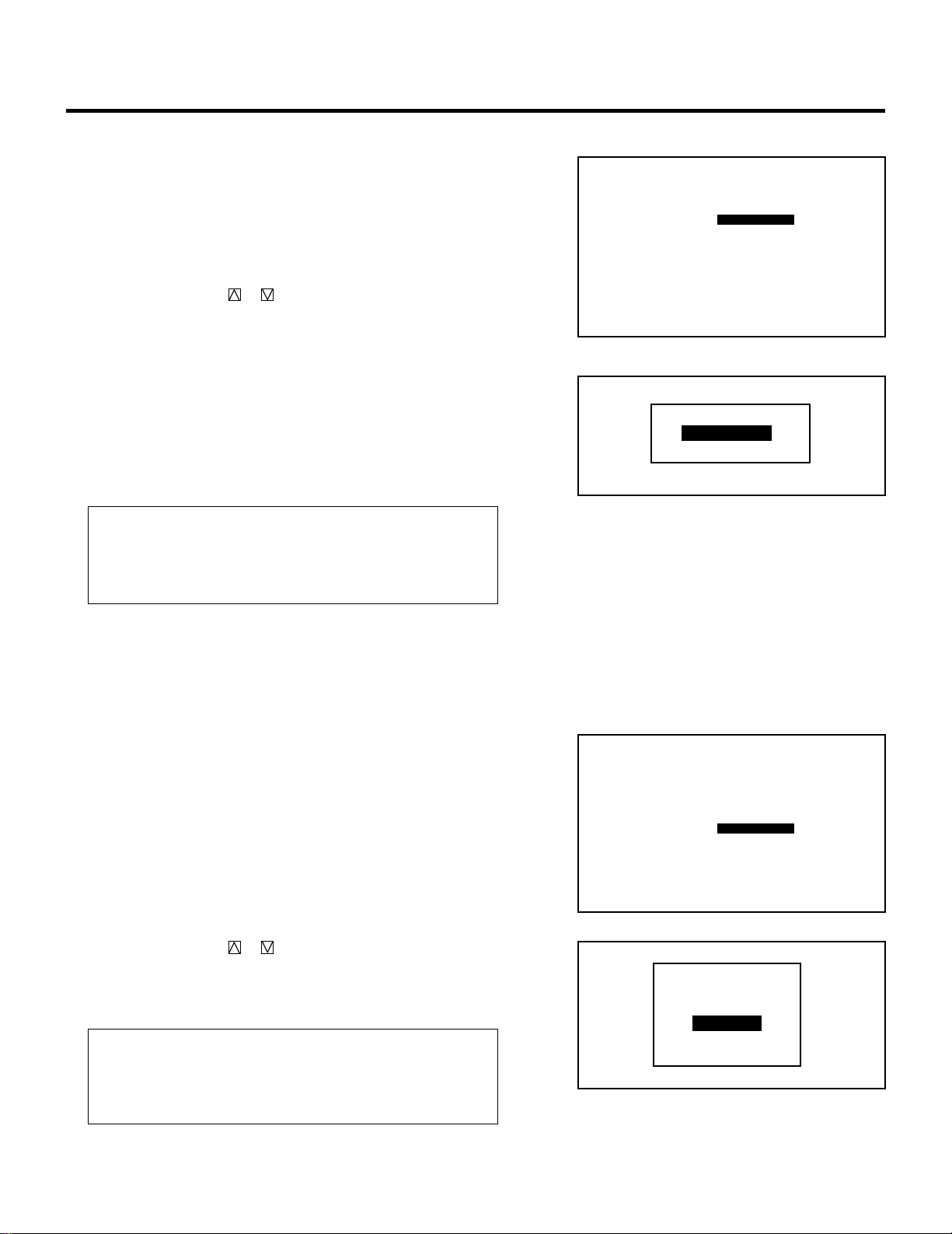
26
m Setting “SYNC DETECT”
This function is used to select the detection method of the sync
signal for an RGB signal.
To do this, proceed as follows:
1) Use the CURSOR buttons to select “SYNC DETECT” and
then press ENTER.
• The “SYNC DETECT” menu will be displayed.
2) Use the CURSOR or button to select either “AUTO” or
“MANUAL” and press ENTER.
• The screen will return to the “SOURCE INFORMATION”
screen.
• When “AUTO” is selected, the sync type will be displayed.
• Select “AUTO” in normal operation.
• Select “MANUAL” when connecting a computer that has a
non-standard signal.
• Selecting “MANUAL” automatically switches to the G-
SYNC mode.
On-screen display
• COMP. --- Composite sync signal.
• SEPA. ---- H/V separate sync signal.
• G-SYNC-- Sync on green signal.
m Setting “COLOR TEMP”
This function is used to select the color temperature of the
projected image.
To do this, proceed as follows:
1) Use the CURSOR buttons to select “COLOR TEMP” and
then press ENTER.
• The “COLOR TEMP” menu will be displayed.
2) Use the CURSOR or button to select the color tempera-
ture you wish to use and then press ENTER.
• The screen will return to the “SOURCE INFORMATION”
screen.
Items to select
• 3200 K...................... Photo color
• 5400K, 6500 K ......... Video application
• 7500K, 9500 K ......... PC, Graphics application
SIGNAL ENTRY
SOURCE INFORMATION
M-01 S-01
FREQUENCY
∗∗∗∗∗∗∗∗
OFF
AUTO COMP.
fh =
fv =
Khz
Hz
∗∗∗ ∗
∗∗ ∗
SYNC
ASTIG
DEFAULT
HD (`) VD (`)
VIDEO MODE
NTSC 3.58
COUNTER TIMER
∗∗∗∗∗ ∗∗
:
.
.
POSITION
WIDE
NAME
COLOR TEMP
6500 K
AKB
OFF
∗∗∗∗
FONT
NORMAL
LOCK
SYNC DETECT
SOURCE INFORMATION
M-01 S-01
FREQUENCY
∗∗∗∗∗∗∗∗
OFF
AUTO COMP.
fh =
fv =
Khz
Hz
∗∗∗ ∗
∗∗ ∗
SYNC
ASTIG
DEFAULT
HD (`) VD (`)
VIDEO MODE
NTSC 3.58
COUNTER TIMER
∗∗∗∗∗ ∗∗
:
.
.
POSITION
WIDE
NAME
6500 K
AKB
OFF
∗∗∗∗
FONT
NORMAL
LOCK
SYNC DETECT
COLOR TEMP
AUTO
MANUAL
SYNC DETECT
3200K
5400K
6500K
7500K
9500K
COLOR TEMP
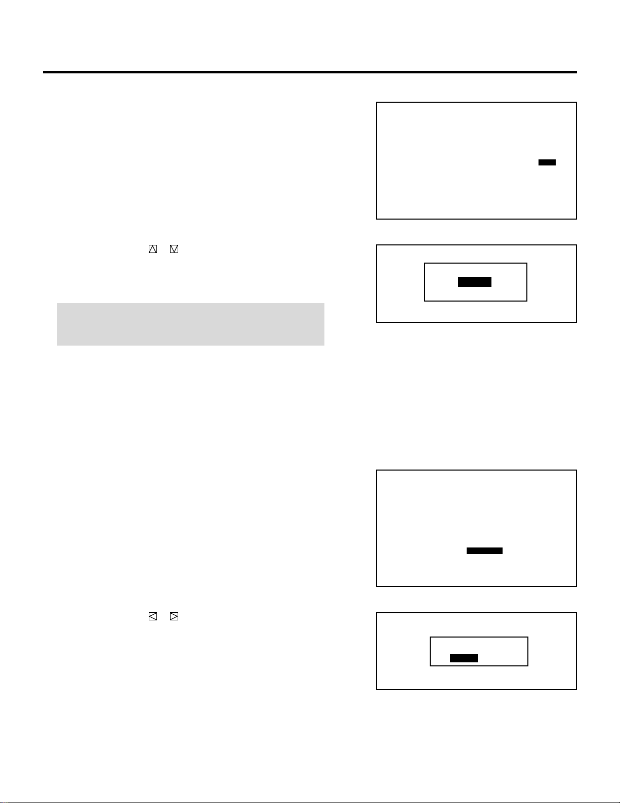
27
SIGNAL ENTRY
m Setting “AKB”
This function is used to activate the auto white balance control.
1) Use the CURSOR buttons to select “AKB” and then press
ENTER.
• The “AKB CONTROL” menu will be displayed.
2) Use the CURSOR or button to select either “ON” or
“OFF” and then press ENTER.
• The screen will return to the “SOURCE INFORMATION”
screen.
NOTE: When “ON” is selected, the AKB detection signal will
appear on the top of the screen. If you wish to remove it, select
“OFF”.
• If the projector is used on the AKB OFF for an extended
period, it could affect the white balance settings. To avoid
this, set AKB to ON periodically.
m Setting “COUNTER”
This function is used to reset the number of times a signal is
selected for display.
1) Use the CURSOR buttons to select the “COUNTER” and
then press ENTER.
• The “COUNTER RESET?” screen will be displayed.
2) Use the CURSOR or button to select either “YES” or
“NO” and then press ENTER.
• To reset the counter, select “YES”. If you do not need to
reset, select “NO”.
• The screen will return to the “SOURCE INFORMATION”
screen.
SOURCE INFORMATION
M-01 S-01
FREQUENCY
∗∗∗∗∗∗∗∗
OFF
AUTO COMP.
fh =
fv =
Khz
Hz
∗∗∗ ∗
∗∗ ∗
SYNC
ASTIG
DEFAULT
HD (`) VD (`)
VIDEO MODE
NTSC 3.58
COUNTER TIMER
∗∗∗∗∗ ∗∗
:
.
.
POSITION
WIDE
NAME
6500 K OFF
∗∗∗∗
FONT
NORMAL
LOCK
SYNC DETECT
COLOR TEMP AKB
SOURCE INFORMATION
M-01 S-01
FREQUENCY
∗∗∗∗∗∗∗∗
OFF
AUTO COMP.
fh =
fv =
Khz
Hz
∗∗∗ ∗
∗∗ ∗
SYNC
ASTIG
DEFAULT
HD (`) VD (`)
VIDEO MODE
NTSC 3.58
TIMER
∗∗∗∗∗ ∗∗
:
.
.
POSITION
WIDE
NAME
6500 K OFF
∗∗∗∗
FONT
NORMAL
LOCK
SYNC DETECT
COLOR TEMP AKB
COUNTER
COUNTER RESET?
YES NO
ON
OFF
AKB CONTROL
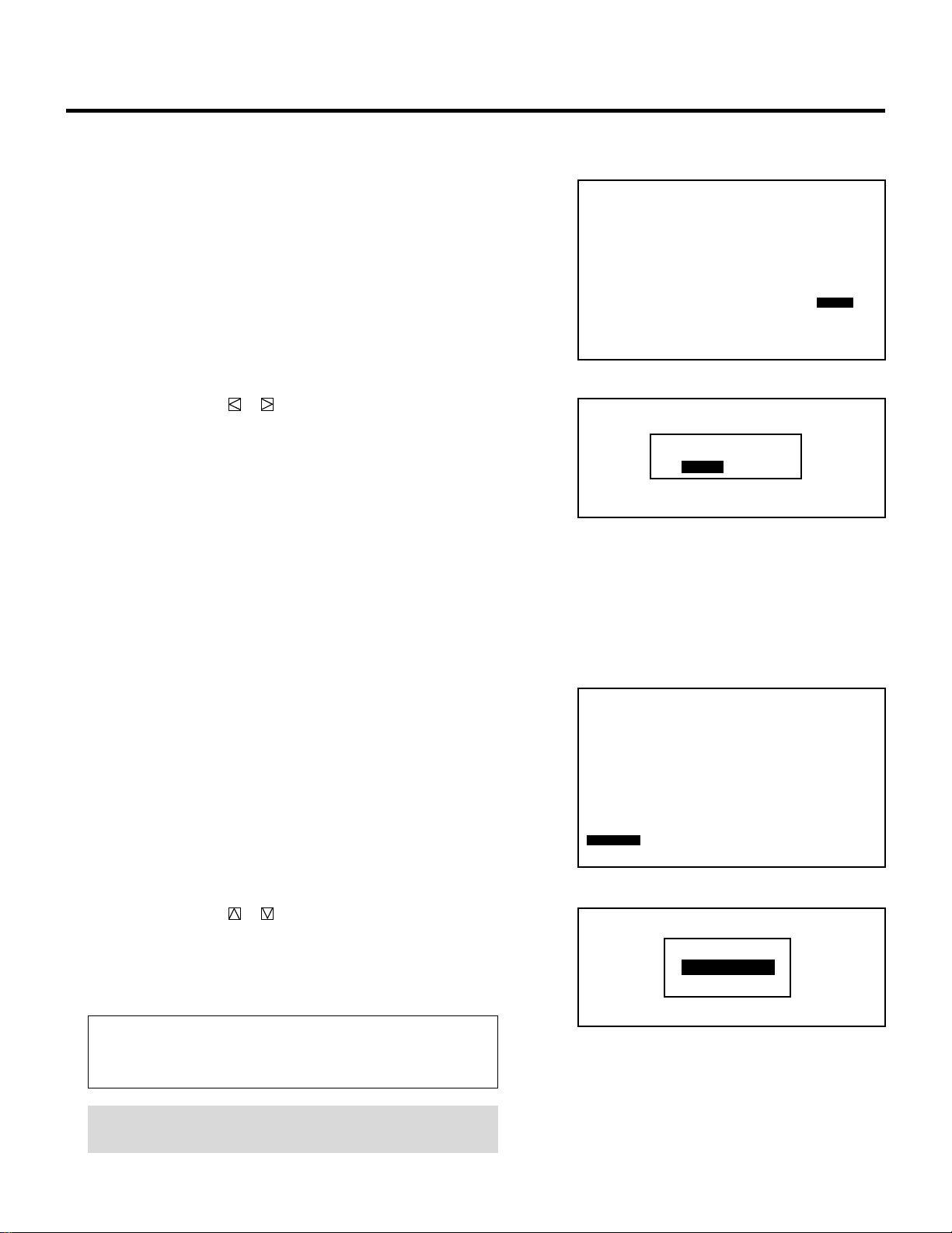
28
SIGNAL ENTRY
m Setting “TIMER”
This function is used to reset the time of signal display.
1) Use the CURSOR buttons to select “TIMER” and then press
ENTER.
• The “TIMER RESET?” screen will be displayed.
2) Use the CURSOR or button to select either “YES” or
“NO” and then press ENTER.
• To reset the timer, select “YES”. If you do not need to
reset, select “NO”.
• The screen will return to the “SOURCE INFORMATION”
screen.
SOURCE INFORMATION
M-01 S-01
FREQUENCY
∗∗∗∗∗∗∗∗
OFF
AUTO COMP.
fh =
fv =
Khz
Hz
∗∗∗ ∗
∗∗ ∗
SYNC
ASTIG
DEFAULT
HD (`) VD (`)
VIDEO MODE
NTSC 3.58
∗∗∗∗∗ ∗∗
:
.
.
POSITION
WIDE
NAME
6500 K OFF
∗∗∗∗
FONT
NORMAL
LOCK
SYNC DETECT
COLOR TEMP AKB
COUNTER TIMER
TIMER RESET?
YES NO
m Selecting “POSITION”
This function is used to select the vertical area mode for the
“POSITION-SHIFT” adjustment.
To do this, proceed as follows:
1) Use the CURSOR buttons to select “POSITION” and then
press ENTER.
• The “POSITION” menu will be displayed.
2) Use the CURSOR or button to select either “WIDE” or
“NARROW” and then press ENTER.
• The screen will return to the “SOURCE INFORMATION”
screen.
• Select “WIDE” in normal operation.
Items to select
• WIDE....... Adjustment area is wide.
• NARROW. Adjustment area is narrow.
NOTE: Selecting “NARROW” may solve problems caused by an
interlace input signal.
SOURCE INFORMATION
M-01 S-01
FREQUENCY
∗∗∗∗∗∗∗∗
OFF
AUTO COMP.
fh =
fv =
Khz
Hz
∗∗∗ ∗
∗∗ ∗
SYNC
ASTIG
DEFAULT
HD (`) VD (`)
VIDEO MODE
NTSC 3.58
∗∗∗∗∗ ∗∗
:
.
.
WIDE
NAME
6500 K OFF
∗∗∗∗
FONT
NORMAL
LOCK
SYNC DETECT
COLOR TEMP AKB
COUNTER TIMER
POSITION
WIDE
NARROW
POSITION

29
SIGNAL ENTRY
m Setting “FONT”
This function is used to specify the appropriate font size to the
on-screen message.
To do this, proceed as follows:
1) Use the CURSOR buttons to select “FONT” and then press
ENTER.
• The “FONT SIZE” menu will be displayed.
2) Use the CURSOR or button to select either “NORMAL”
or “SMALL” and then press ENTER.
• The screen will return to the “SOURCE INFORMATION”
screen.
Items to select
• NORMAL . Calculates the appropriate font size with the
vertical scanning lines to display the on-screen
message in the appropriate size.
• SMALL .... Displays the on-screen message in the font size of
75 percent of the NORMAL size.
SOURCE INFORMATION
M-01 S-01
FREQUENCY
∗∗∗∗∗∗∗∗
OFF
AUTO COMP.
fh =
fv =
Khz
Hz
∗∗∗ ∗
∗∗ ∗
SYNC
ASTIG
DEFAULT
HD (`) VD (`)
VIDEO MODE
NTSC 3.58
∗∗∗∗∗ ∗∗
:
.
.
WIDE
NAME
6500 K OFF
∗∗∗∗
NORMAL
LOCK
SYNC DETECT
COLOR TEMP AKB
COUNTER TIMER
POSITION
FONT
NORMAL
SMALL
FONT SIZE
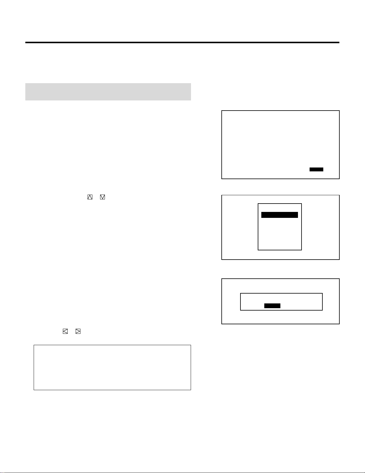
30
SIGNAL ENTRY
m Setting “ASTIG”
This function is used to set memory space that is used for ASTIG
data storage.
NOTE: Use the USER memory area (USER-1 through 5) when
adjusting ASTIG. Set to DEFAULT normally.
1) Use the CURSOR buttons to select “ASTIG” and then press
ENTER.
• The ASTIG memory area menu is displayed.
2) Use the CURSOR or button to select any one of the
ASTIG memory areas and then press ENTER.
4 To complete, press the END button.
• Whenever the END button is pressed, the menus will sequence
in this order:
“ADJUST” menu → Source screen
• When your passcode is in effect, the “RETURN USER
MODE?” screen is displayed. If this happens, use the
CURSOR or button to select either “YES” or “NO” and
press ENTER.
Items to select
• YES ......... When you try to enter the ADJUST mode the next
time, you will need to re-enter your passcode.
• NO........... When you try to enter the ADJUST mode the next
time, you will not need to re-enter your passcode.
SOURCE INFORMATION
M-01 S-01
FREQUENCY
∗∗∗∗∗∗∗∗
OFF
AUTO COMP.
fh =
fv =
Khz
Hz
∗∗∗ ∗
∗∗ ∗
SYNC
DEFAULT
HD (`) VD (`)
VIDEO MODE
NTSC 3.58
∗∗∗∗∗ ∗∗
:
.
.
WIDE
NAME
6500 K OFF
∗∗∗∗
NORMAL
LOCK
SYNC DETECT
COLOR TEMP AKB
COUNTER TIMER
POSITION
FONT
ASTIG
RETURN USER MODE?
YES NO
DEFAULT
USER-1
USER-2
USER-3
USER-4
USER-5
ASTIG
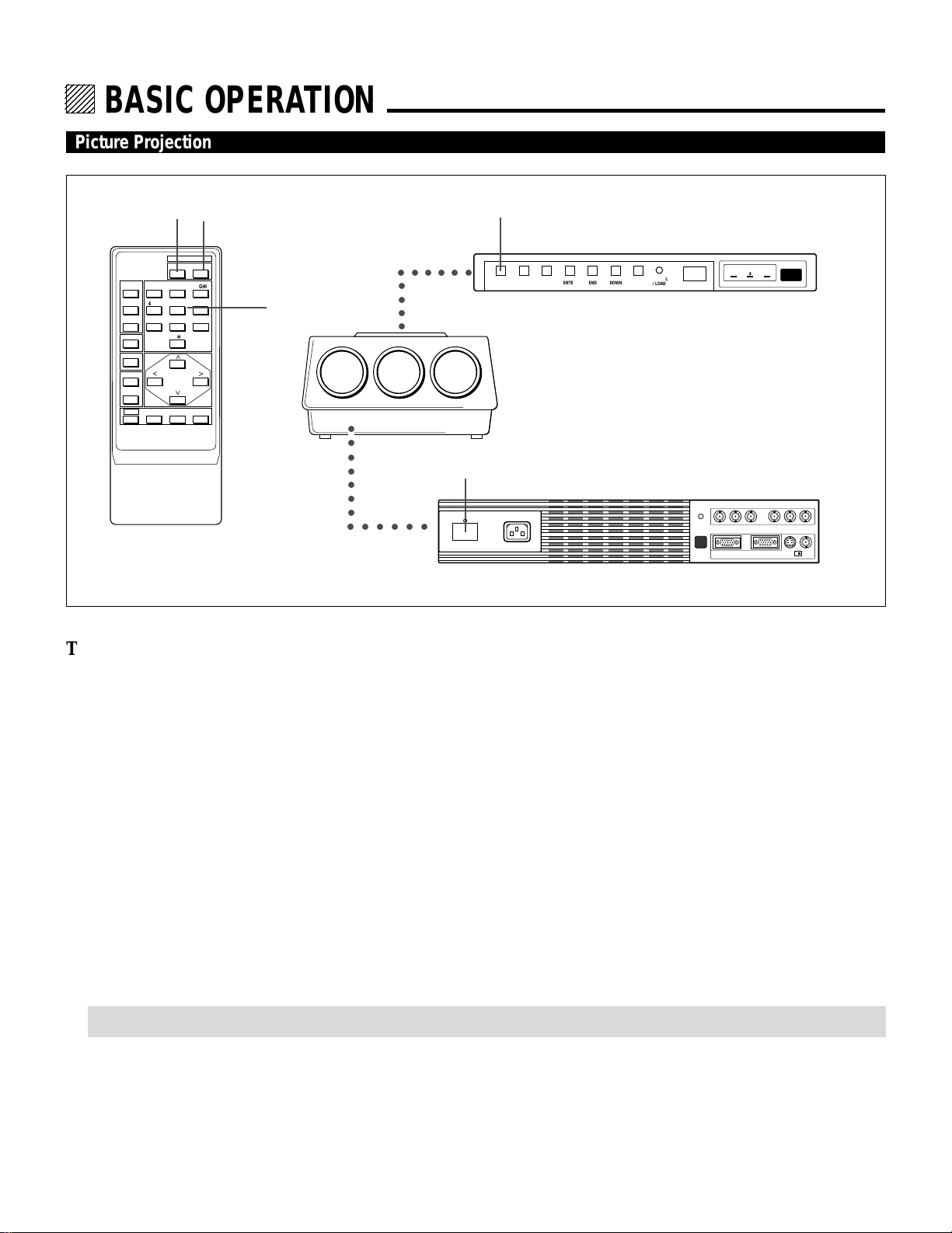
16
12345
6
12345
6
12345
6
12345
6
12345
6
123456
BASIC OPERATION.
Picture Projection
To project a picture source, proceed as follows:
1 Turn on the main power of the projector.
• Press the POWER switch on the front terminal panel.
2 Turn on the power of the connected equipments.
3 Turn on the power of the projector.
• Press the POWER ON button on the remote control or the POWER button on the rear panel.
4 Select an input signal source by pressing one of the ten INPUT buttons on the remote control. You can also select a signal from
the “INPUT SELECT” list.
• See “INPUT SELECTION” on page 23 for more details.
5 Adjust the picture and sound.
• See pages 19 through 22 for more details.
NOTE: The volume function works only with the ISS-6010/ISS-6010G Switcher.
6 To turn off the power, press the POWER OFF button on the remote control or the POWER button on the rear panel.
7 Press the POWER switch on the front terminal panel to turn off the main power of the projector.
8 Last, turn off the connected equipment power.
REMOTE 2
R G B H / V V
REMOTE 1 OPTION 1
S-VIDEO VIDEO
POWER AC INPUT
ACAT
H/V&V
HIGH 75Ω
1 7
○○○○○○○○
○○○○○
○○○○○○
Projector
Front terminal panel
UP
NORMAL
/ LOAD
DOWNENDENTEROPERATECONTROLPOWER
POWERSTANDBYREMOTE
3 6
○○○○○○
3 6
POWER
ON OFF
OPERATE
PICTURE
MUTE
SOUND
MUTE
1 ABC 2 DEF 3 GHI
4 JKL 5 MNO 6 PQR
7 STU 8 VWX 9 YZ /
10 ,.
R
B
ENDCTL
DISPLAY
STATIC
NORMAL ENTER
4
User remote control
Rear control panel
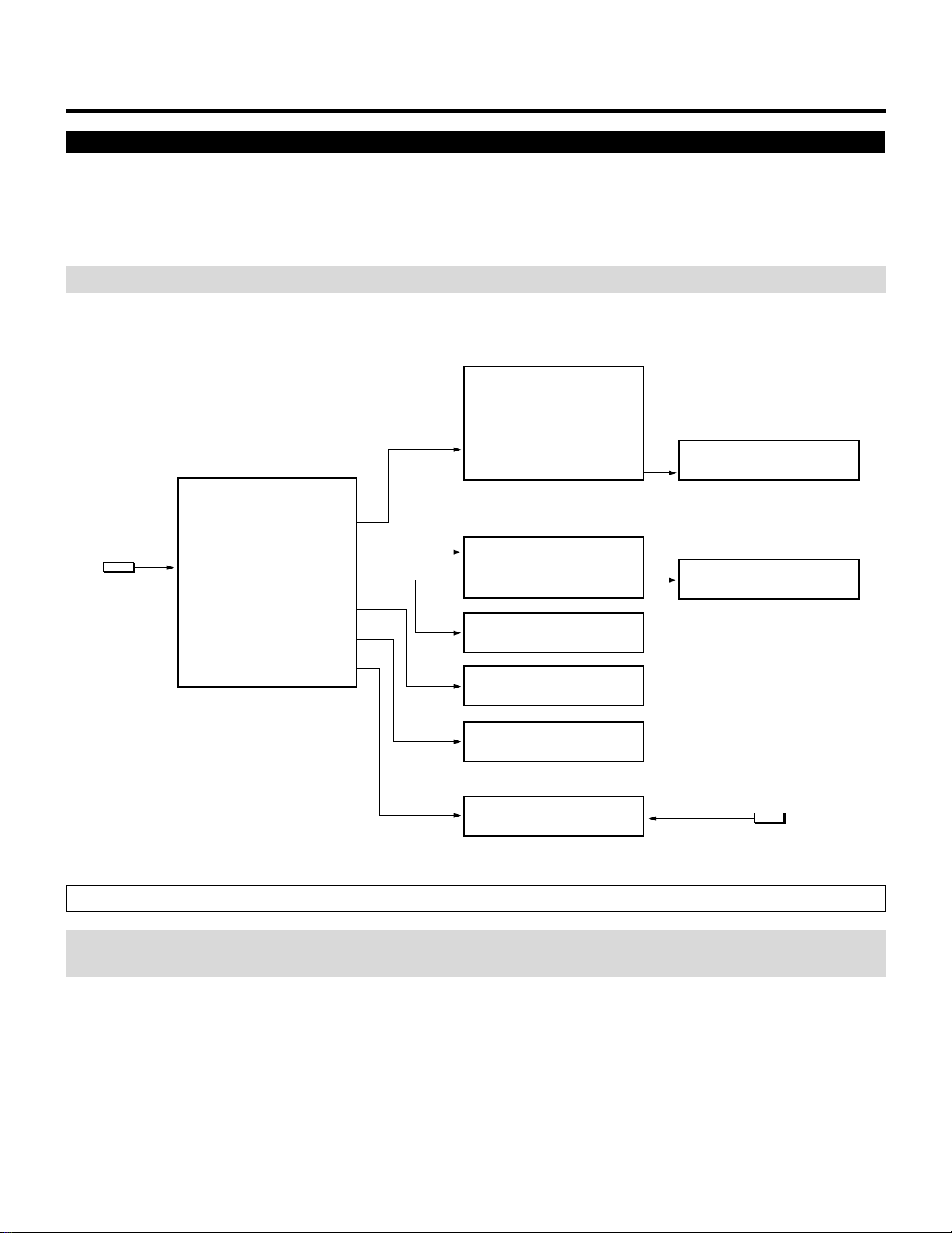
17
Displaying the Menu and Adjustment Screens
You can easily access your desired screen by selecting menus.
Depending upon button selection, your desired screen will be displayed as shown below:
OPERATE menu
NOTE: The examples of the screen display in the following pages are for use with the ISS-6010/ISS-6010G Switcher.
OPERATE
OPERATE menu
– OPERATE –
1 / PICTURE
2 / POSITION
3 / SOUND
4 / INPUT SELECT
5 / SOURCE INFO
6 / STATIC
– PICTURE –
1 / BRIGHT
2 / CONTRAST
3 / COLOR
4 / SHARPNESS
5 / TINT
PICTURE menu
– POSITION –
1 / SHIFT
2 / BLANKING
POSITION menu
STATIC
Adjustment screen
SOURCE
INFORMATION screen
Adjustment screen
Adjustment screen
INPUT SELECT screen
Adjustment screen
• The SOUND item is not included
in the stand alone OPERATE
menu.
CAUTION: Do not display a bright and still picture for longer than 20 minutes. This could damage the CRTs.
NOTE: The explanation of the operation on the following pages is for use with the remote control. You can also operate the
projector using the buttons on the control panel of the projector.
BASIC OPERATION
• Some function items will not be available depending on the type of video signal.
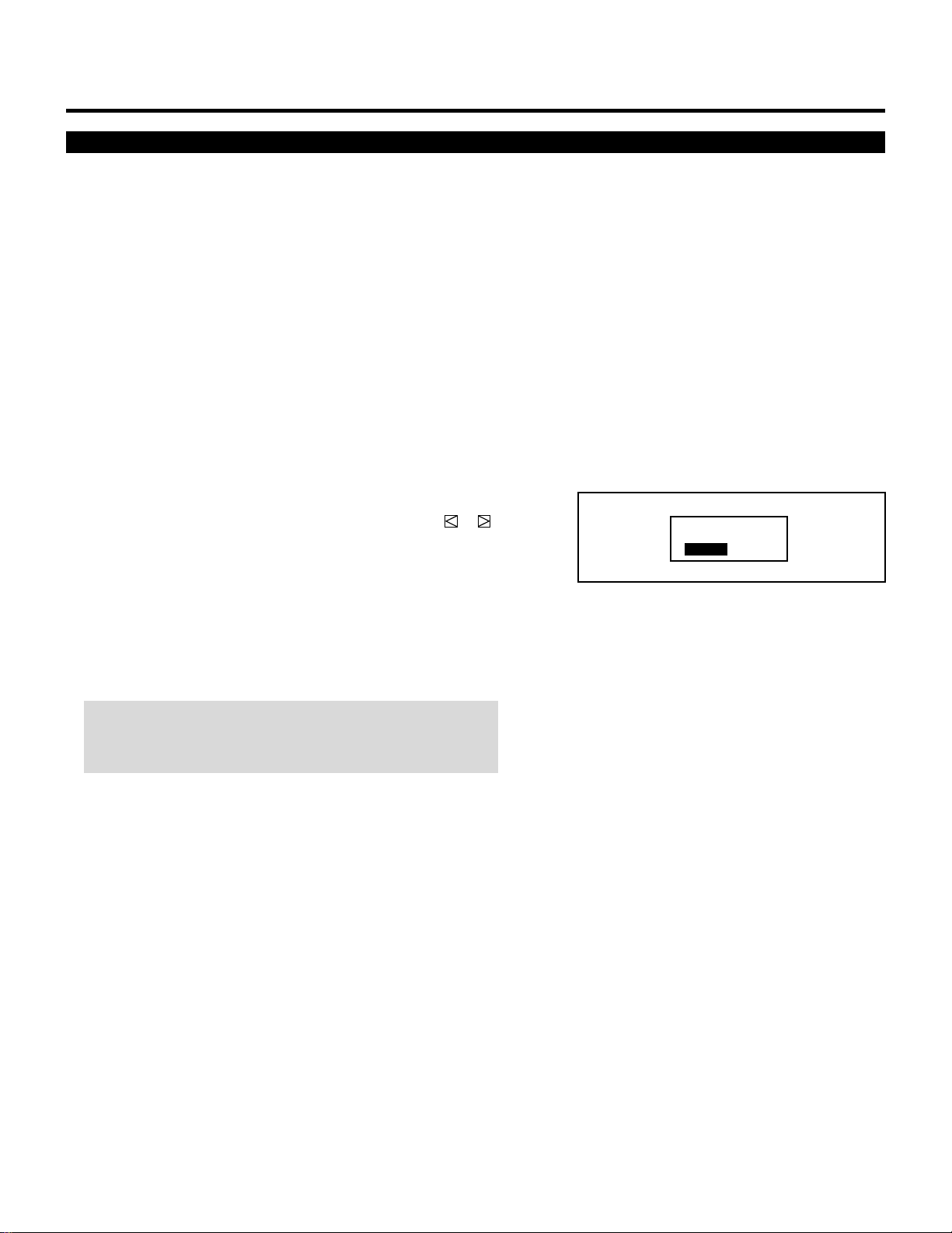
18
BASIC OPERATION
Storing Projector Settings (Automatic Save Feature)
You have two options to store projector settings in the memory:
automatically and manually.
mWhen the Automatic Save Feature mode is set to “ENABLE”,
projector settings will be stored in the projector's memory
automatically.
Storing settings are done when any one of the following proce-
dures is performed:
• The END button is pressed several times to return the adjust-
ment screen to the source screen.
• One input is switched to another.
• The projector is turned off.
mWhen the Automatic Save Feature mode is set to “DISABLE”,
projector settings can be stored in the projector's memory
manually.
If the current status is not stored due to pressing another button,
the “STORE ?” message is displayed. Use the CURSOR or
button to select either “YES” or “NO” and press the ENTER
button.
• If the adjustments have not been changed, the “STORE ?”
message is not displayed.
• To exit the mode without storing the current status, select
“NO”.
NOTE: The Automatic Save Feature mode has been set to
DISABLE by factory. For information on setting, contact your
dealer.
STORE?
YES NO
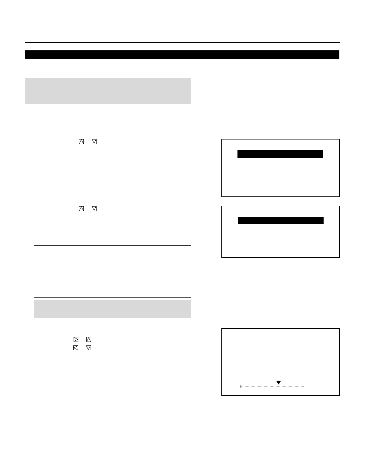
19
BASIC OPERATION
Picture Adjustment
To adjust the picture for each input, proceed as follows:
NOTE: The color, sharpness, and tint controls are not included in
the “PICTURE” menu for RGB signal. The tint control is not in the
“PICTURE” menu for SECAM/PAL signal.
1 Press the OPERATE button.
• The “OPERATE” menu is displayed.
2 Use the CURSOR or button to highlight the “1/PICTURE”
line and press ENTER to display the “PICTURE” menu. You can
also select the “PICTURE” menu directly by pressing the INPUT
“1” button.
• The “3/SOUND” item is not included in the stand alone operate
menu.
3 Use the CURSOR or button to select a picture function and
then press ENTER. You can also select an item directly by
pressing the corresponding number button.
• The picture adjustment screen will be displayed.
Items to select:
• BRIGHT (Brightness control)
• CONTRAST (Contrast control)
• COLOR (Color intensity control)
• SHARPNESS (Picture detail control)
• TINT (Red and green values control)
NOTE: When you are in the BRIGHT adjustment mode, all the
CRTs will be in use. The CRT beam cannot be cut-off.
4 Use the CURSOR buttons to adjust a picture to your preference.
• The CURSOR or button increases the level.
The CURSOR or button decreases the level.
5 To end this adjustment, press the END button.
• Wherever the END button is pressed, the screen changes in this
order:
“PICTURE” menu → ”OPERATE” menu → Source screen
– OPERATE –
1 / PICTURE
2 / POSITION
3 / SOUND
4 / INPUT SELECT
5 / SOURCE INFO
6 / STATIC
– PICTURE –
1 / BRIGHT
2 / CONTRAST
3 / COLOR
4 / SHARPNESS
5 / TINT
PICTURE
- BRIGHT -
60%
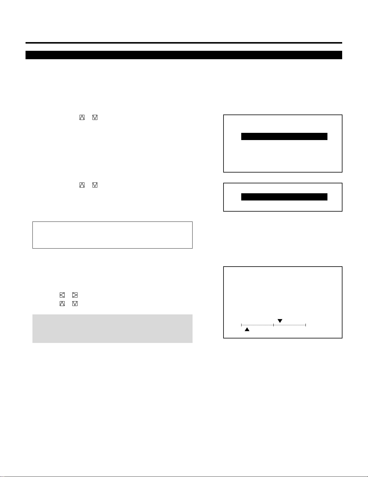
20
BASIC OPERATION
Position Adjustment
Adjust the position(SHIFT) and the screen area (BLANKING).
Proceed as follows:
1 Press the OPERATE button.
• The “OPERATE” menu is displayed.
2 Use the CURSOR or button to highlight the “2/POSITION”
line and press ENTER to display the “POSITION” menu. You
can also select the “POSITION” menu directly by pressing the
INPUT “2” button.
• The “3/SOUND” item is not included in the stand alone operate
menu.
3 Use the CURSOR or button to select either “SHIFT” or
“BLANKING” and then press ENTER. You can also select each
item directly by pressing the INPUT “1” or “2” button.
• The selected adjustment screen will be displayed.
Items to select
• SHIFT(Position of the picture)
• BLANKING(Screen area)
4 Adjust the position or screen area.
When selecting SHIFT:
Use the CURSOR buttons to move the position of the picture.
• Pressing or moves the picture left or right.
• Pressing or moves the picture up or down.
NOTE: Adjust to position the picture in the center of the raster.
Over shift-adjusting to the top of the raster may cause the top
of the picture to curve depending on the type of input signal.
– OPERATE –
1 / PICTURE
2 / POSITION
3 / SOUND
4 / INPUT SELECT
5 / SOURCE INFO
6 / STATIC
– POSITION –
1 / SHIFT
2 / BLANKING
POSITION
- SHIFT -
H
V
`10%
190%
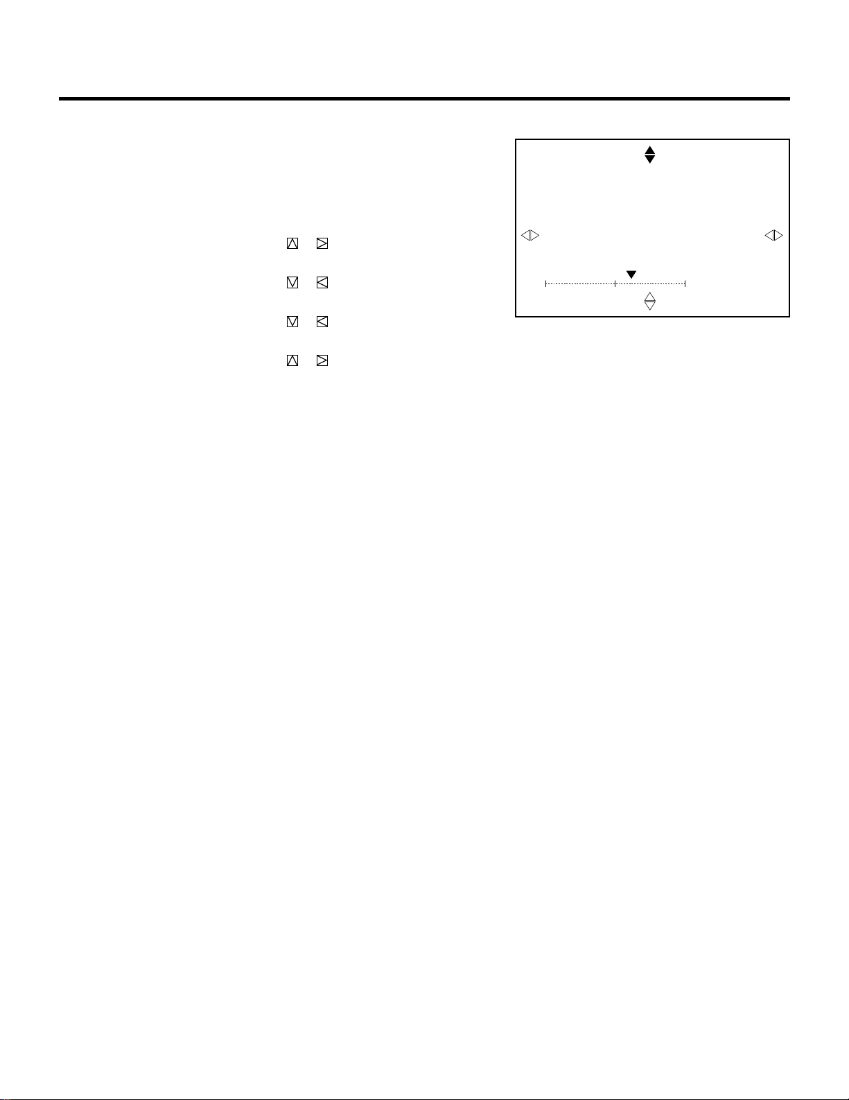
21
BASIC OPERATION
When selecting BLANKING:
1) Hold down the CTL button and press CURSOR buttons to
choose the right, left, top, or bottom edge.
• The marker on the selected side will turn to a solid color.
2) Adjust the blanking using the CURSOR buttons.
Top (U) and Right (R) ....... Pressing or increases the
adjustment values.
Pressing or decreases the
adjustment values.
Bottom (D) and Left (L) .... Pressing or increases the
adjustment values.
Pressing or decreases the
adjustment values.
5 To end this adjustment, press the END button.
• Whenever the END button is pressed, the screen changes in this
order:
“POSITION” menu → ”OPERATE” menu → Source screen
POSITION
- BLANKING -
60%
U
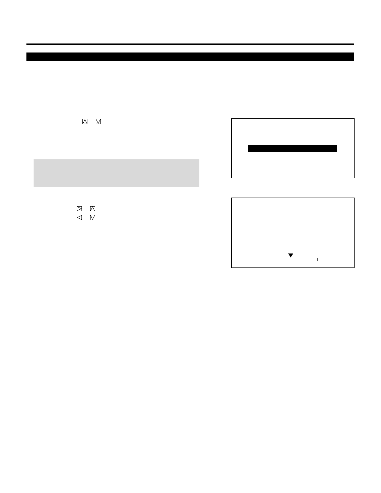
22
Sound Adjustment (only when used with the ISS-6010/ISS-6010G Switcher)
Adjust the volume to your preference.
Proceed as follows:
1 Press the OPERATE button.
• The “OPERATE” menu is displayed.
2 Use the CURSOR or button to highlight the “3/SOUND”
line and press ENTER to display the “VOLUME” screen. You
can also select the “VOLUME” screen directly by pressing the
INPUT “3” button.
NOTE: You can enter the VOLUME adjustment screen directly
using the SOUND FUNC button on the full function remote
control.
3 Use the CURSOR buttons to adjust the volume.
• The CURSOR or button increases the volume.
The CURSOR or button decreases the volume.
4 To end this adjustment, press the END button.
• Whenever the END button is pressed, the screen changes in this
order:
“OPERATE” menu → Source screen.
BASIC OPERATION
– OPERATE –
1 / PICTURE
2 / POSITION
3 / SOUND
4 / INPUT SELECT
5 / SOURCE INFO
6 / STATIC
SOUND
- VOLUME -
60%
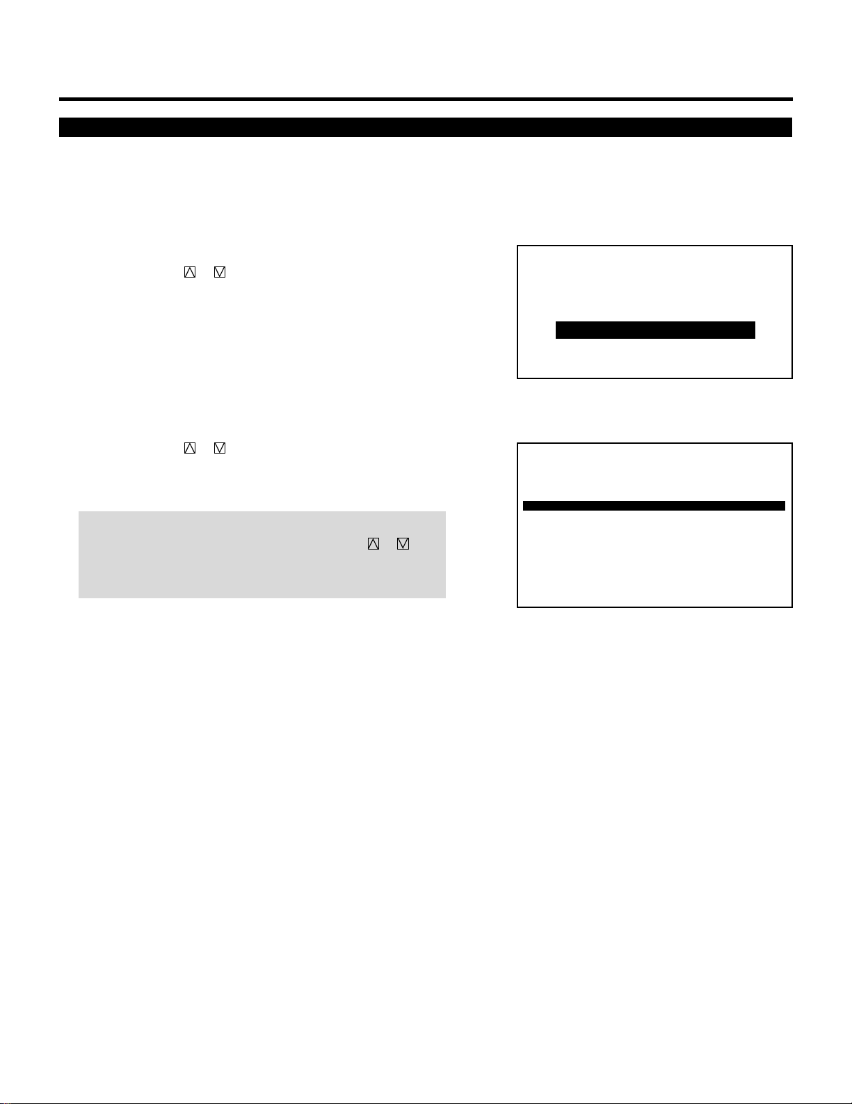
23
Input Selection
BASIC OPERATION
You can switch from one input to any other input signal.
Proceed as follows:
1 Press the OPERATE button.
• The “OPERATE” menu is displayed.
2 Use the CURSOR or button to highlight the “4/INPUT
SELECT” line and press ENTER to display the “INPUT SE-
LECT” list. You can also select the “INPUT SELECT” list
directly by pressing the INPUT “4” button.
• The “3/SOUND” item is not included in stand alone operate
menu.
• When the projector is used in stand alone operation, the third
item is “3/INPUT SELECT”.
3 Use the CURSOR or button to highlight the signal to be
switched to and press ENTER to switch to the selected input
signal.
NOTE: To advance to the next page or to the previous page,
hold down the CTL button then press the CURSOR or
button. To directly access the page, hold down the CTL button
then any one of the INPUT buttons.
4 To end the INPUT SELECT list, press the END button.
• Whenever the END button is pressed, the screen changes in this
order:
“OPERATE” menu → Source screen
– OPERATE –
1 / PICTURE
2 / POSITION
3 / SOUND
4 / INPUT SELECT
5 / SOURCE INFO
6 / STATIC
P01
ISS-6010 SW 2 LEVEL
NO INPUT NAME DATE
0 1 M – 01 S – 01 VTR – 1 12 / 01 / 90
0 2 M – 01 S – 02 VTR – 2 12 / 03 / 90
0 3 M – 01 S – 03 VIDEO-1 12 / 11 / 90
0 4 M – 01 S – 04 VTR – 3 12 / 24 / 90
0 5 M – 01 S – 05 RGB-1 12 / 25 / 90
0 6 M – 01 S – 06 VIDEO-2 12 / 30 / 90
0 7 M – 01 S – 07 VIDEO-3 12 / 31 / 90
0 8 M – 01 S – 08 NTSC 01 / 15 / 91
0 9 M – 01 S – 09 P A L 01 / 16 / 91
1 0 M – 01 S – 10 SECAM 01 / 29 / 91
INPUT SELECT
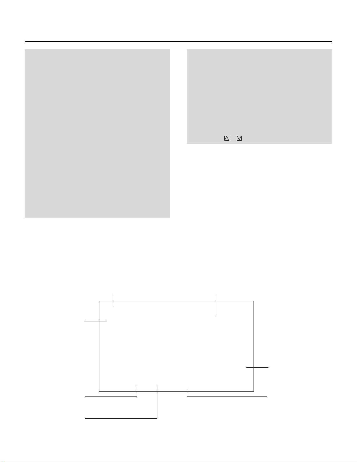
24
NOTE:
• While you are viewing a source screen, you can also select
the input signal directly by pressing the INPUT “1”
through “10” button. In this case INPUT buttons function
as follows:
When using the projector in stand alone operation:
INPUT 1 → Selects the VIDEO input on the projector
INPUT 2 → Selects the RGB input on the projector
INPUT 3 → Selects the S-VIDEO input on the projector
When using the projector with the ISS-6010/ISS-6010G:
INPUT 1 through 10 → Selects the corresponding number
slot of the ISS-6010/ISS-6010G
When using the projector with two ISS-6010/ISS-6010G or more:
To switch to another input signal, enter the master slot
number, then the slave slot number by using INPUT
buttons and press ENTER.
For example:If you want to select a signal from the no.3 slot of
the slave Switcher which is connected to the no.2 slot of the
master Switcher, first press the INPUT “2” button, then the
INPUT “3” button and finally press ENTER.
• You can switch to any input signal of NO 01 through10 on
the INPUT SELECT list by holding down the CTL button
and pressing one of the INPUT buttons corresponding to
the input number. Prior to this, you are required to select
ENABLE in the DIRECT ENTRY ACCESS mode. For further
details, contact your dealer.
• When pressing any one of the INPUT buttons to directly
access one signal among two or more of the same signals,
the projector will output the signal listed in the upper line
automatically. To select the one listed in the lower line, use
the CURSOR or button and press ENTER.
BASIC OPERATION
P01
ISS-6010 SW 2 LEVEL
NO INPUT NAME DATE
0 1 M – 01 S – 01 VTR – 1 12 / 01 / 90
0 2 M – 01 S – 02 VTR – 2 12 / 03 / 90
0 3 M – 01 S – 03 VIDEO-1 12 / 11 / 90
0 4 M – 01 S – 04 VTR – 3 12 / 24 / 90
0 5 M – 01 S – 05 RGB-1 12 / 25 / 90
0 6 M – 01 S – 06 VIDEO-2 12 / 30 / 90
0 7 M – 01 S – 07 VIDEO-3 12 / 31 / 90
0 8 M – 01 S – 08 NTSC 01 / 15 / 91
0 9 M – 01 S – 09 P A L 01 / 16 / 91
1 0 M – 01 S – 10 SECAM 01 / 29 / 91
INPUT SELECT
Page (P01 to P10)
The Switcher connected
Slot number of the master
Switcher
Slot number of the slave
Switcher
Date registered
Connection condition of the Switcher
Source name of input signal
INPUT SELECT List Format
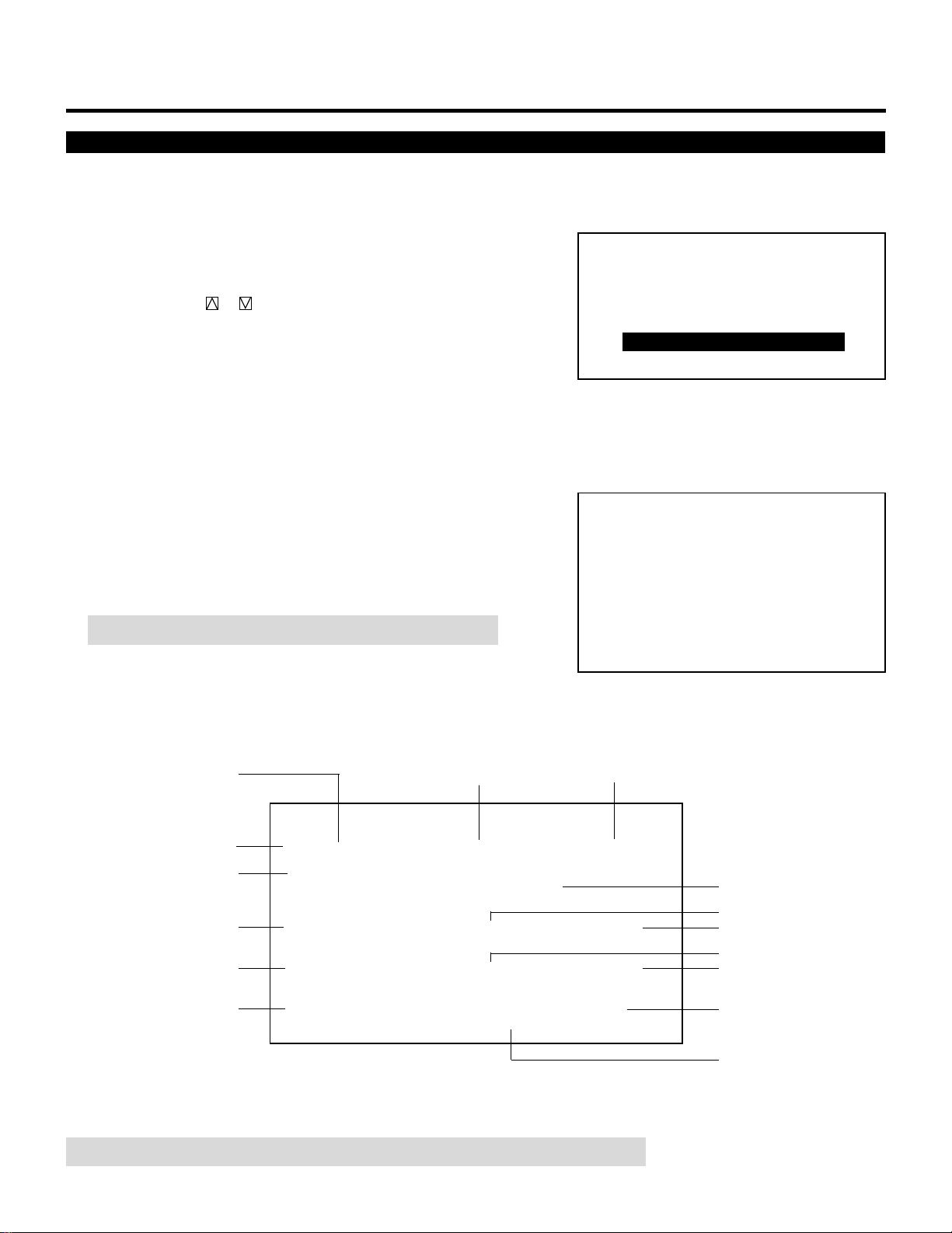
25
Source Information
NOTE: The above screen display is an example when used with the ISS-6010/ISS-6010G.
BASIC OPERATION
This is for viewing the signal information and the current status of
various setting.
Proceed as follows:
1 Press the OPERATE button.
• The “OPERATE” menu is displayed.
2 Use the CURSOR or button to highlight the “5/SOURCE
INFO” line and press ENTER to display the “SOURCE INFOR-
MATION” screen. You can also select the “SOURCE INFOR-
MATION” screen directly by pressing the INPUT “5” button.
• The “3/SOUND” item is not included in stand alone operate
menu.
• When the projector is used in stand alone operation, the fourth
item is “ 4/SOURCE INFO”.
3 To end the “SOURCE INFORMATION” screen, press the END
button.
• Whenever the END button is pressed, the screen changes in this
order:
“OPERATE” menu → Source screen
NOTE: The items below are not available in the OPERATE mode.
– OPERATE –
1 / PICTURE
2 / POSITION
3 / SOUND
4 / INPUT SELECT
5 / SOURCE INFO
6 / STATIC
SOURCE INFORMATION
M-01 S-01
FREQUENCY
LOCK
∗∗∗∗∗∗∗∗
OFF
SYNC DETECT
AUTO COMP.
fh =
fv =
KHz
Hz
∗∗∗ ∗
∗∗ ∗
SYNC
ASTIG
DEFAULT
HD (`) VD (`)
VIDEO MODE
NTSC 3.58
COUNTER TIMER
∗∗∗∗∗ ∗∗
:
.
.
POSITION
WIDE
NAME
COLOR TEMP
6500 K
AKB
OFF
∗∗∗∗
FONT
NORMAL
Source lock for RGB signal
Sync signal
Color temperature
Auto white balance ON/OFF
ASTIG memory area
Source name of input signal
Vertical position mode
Video color system
Scanning frequency
SYNC input polarity
Number of times of signal display
Time of signal display
Slot number of the master
switcher
Slot number of the slave
switcher
SOURCE INFORMATION
M-01 S-01
FREQUENCY
LOCK
∗∗∗∗∗∗∗∗
OFF
SYNC DETECT
AUTO COMP.
fh =
fv =
KHz
Hz
∗∗∗ ∗
∗∗ ∗
SYNC
ASTIG
DEFAULT
HD (`) VD (`)
VIDEO MODE
NTSC 3.58
COUNTER TIMER
∗∗∗∗∗ ∗∗
:
.
.
POSITION
WIDE
NAME
COLOR TEMP
6500 K
AKB
OFF
∗∗∗∗
FONT
NORMAL
Currently selected font size mode
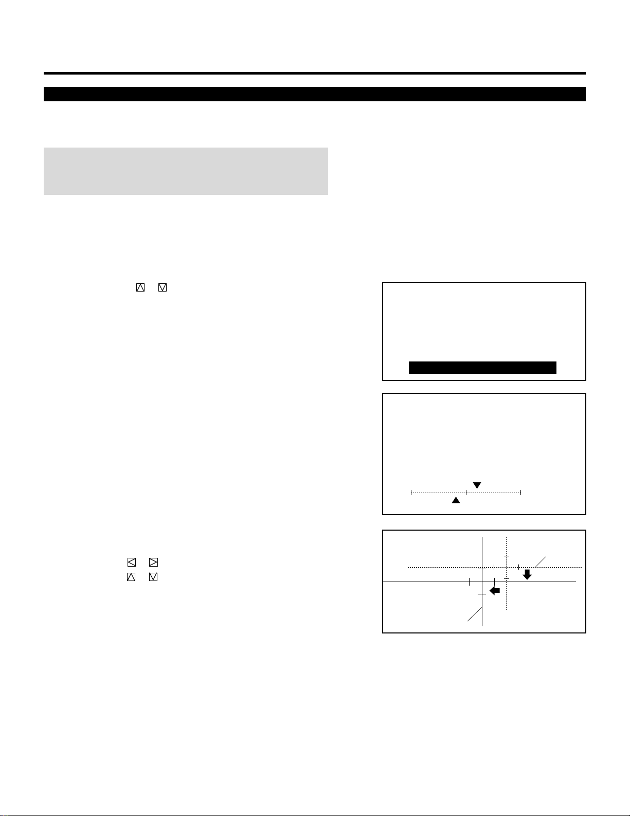
26
Static Convergence Adjustment
BASIC OPERATION
Adjust for the red and blue CRTs to place their pattern on top of the
green test pattern (center only).
NOTE: The static convergence adjustment should be performed for
R and B CRT. Carry out the adjustment after displaying an active
image for 20 minutes or more.
Proceed as follows:
1 Press the OPERATE button.
• The “OPERATE” menu is displayed.
2 Use the CURSOR or button to highlight the “6/STATIC line
and then press ENTER to display the STATIC adjustment screen.
You can also select the STATIC adjustment screen directly by
pressing the INPUT “6” button.
• The “3/SOUND” item is not included in stand alone operate
menu.
• When the projector is used in stand alone operation, the fifth
item is “5/STATIC”.
• The CROSS-HAIR test pattern will be automatically displayed.
3 Press the R or B button to display the pattern to be aligned with
the Green pattern (as used a reference color).
• You can turn on or off each CRT beam (R and B) separately.
4 Hold down the CTL button then select the CRT you wish to
adjust with the R and B buttons.
5 Align the center of the Red or the Blue pattern with the center of
the Green pattern using the CURSOR buttons.
• The CURSOR or button moves the pattern right or left.
The CURSOR or button moves the pattern up or down.
6 Repeat steps 3 to 5 for the other CRTs if necessary.
7 To end this adjustment, press the END button.
• Whenever the END button is pressed, the screen changes in this
order:
“OPERATE” menu → Source screen
– OPERATE –
1 / PICTURE
2 / POSITION
3 / SOUND
4 / INPUT SELECT
5 / SOURCE INFO
6 / STATIC
CONVERGENCE
- STATIC -
`10%
CRT - R -
110%
H
V
Red or Blue
Green

27
BASIC OPERATION
Picture and Sound Mute
Normal, Load, and Cancel Function
Adjustment settings can be returned to the factory preset level, or the
previously stored level, or can be cancelled.
To return to the standard level (NORMAL):
1 Press the NORMAL button.
• A confirmation message will be displayed.
2 Use the CURSOR or button to select “YES”.
3 Press ENTER.
• The NORMAL function is performed.
• If you select “NO”, you will exit this mode suspending current
status.
To return to the last stored level (LOAD):
1 Press and hold the CTL button then press the NORMAL button.
• The “LOAD/CANCEL” menu is displayed.
2 Use the CURSOR or button to select “LOAD”.
• A confirmation message is displayed.
3 Use the CURSOR or button to select “YES”.
• If you select “NO”, you will exit this mode suspending current
status.
4 Press ENTER.
• The LOAD function is performed.
To cancel the adjustment data (CANCEL):
1 Press and hold the CTL button then press the NORMAL button.
• The “LOAD/CANCEL” menu is displayed.
2 Use the CURSOR or button to select “CANCEL”.
• A confirmation message is displayed.
3 Use the CURSOR or button to select “YES”.
• If you select “NO”, you will exit this mode suspending current
status.
4 Press ENTER.
• The CANCEL function is performed.
XXXXXXXX refers to a specific adjustment item to be
loaded or cancelled
XXXXXXXX refers to a specific adjustment item to be
loaded
XXXXXXXX refers to a specific adjustment item to be
cancelled
XXXXXXXX refers to a specific adjustment item to be
normalized
XXXXXXXX
DATA NORMALIZE?
YES NO
XXXXXXXX
DATA LOAD?
YES NO
XXXXXXXX
DATA CANCEL?
YES NO
XXXXXXXX
LOAD
CANCEL
This function mutes a picture or sound.
To mute picture or sound:
• Pressing PICTURE MUTE mutes picture.
Pressing SOUND MUTE mutes sound.
Pressing again PICTURE MUTE/SOUND MUTE restores the picture or sound. Another way to restore picture or sound is to
press END.
NOTE: The OPERATE and the ADJUST menus can be accessed in the PICTURE MUTE mode.
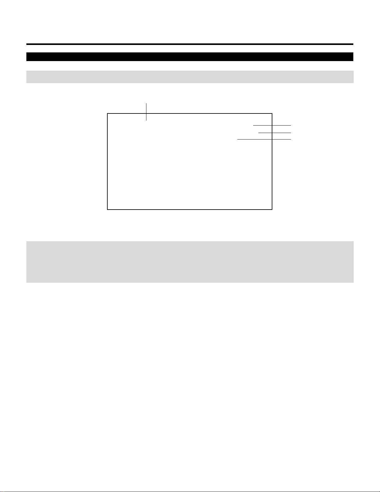
28
BASIC OPERATION
Screen Format in Projecting a Picture
NOTE: The example of the screen display is only when used with the ISS-6010/ISS-6010G.
NOTE:
• Contact your dealer for changing the on-screen display mode.
• If the main power is not supplied to the projector for three days or more, the built-in clock may be reset. If this happens, contact
your dealer for setting date and time.
MON 01/16/95 12:00:00
M-01 S-01
XXXX
Date
Current time
Input
Source name
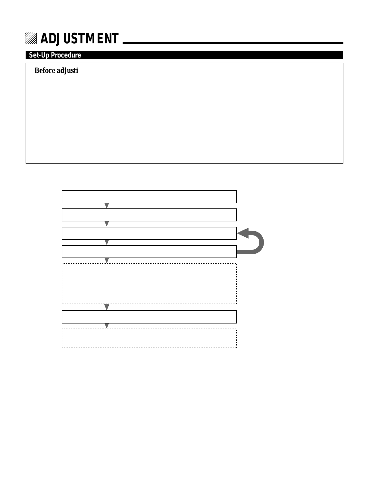
31
123456
12345
6
12345
6
12345
6
12345
6
12345
6
123456
ADJUSTMENT.
Set-Up Procedure
Before adjusting
1 Installation of the projector.
• This projector is pre-adjusted at the factory for 100 inch screen front projection at 11 degrees and ceiling mounting. If
your application is the same as the factory setting, you will not have to reconfigure the projector for your application.
However, if you want to do some fine or further adjustments, carry out the following adjustments.
2 Connect the external equipment to the projector.
3 Turn on power to the external equipment and the projector.
• If you want to institute the use of a passcode, register the passcode.
• Carry out the adjustments after displaying an image for 20 minutes or more.
4 Select the input signal.
• If your input signal has not been recorded, it is necessary to perform the signal entry beforehand. See page 16.
If you want to use the projector in any other configuration than the factory setting, perform the following after installation.
1) Electrical Focus Adjustment See page 32
2) Alignment Adjustment See page 36
3) Static Convergence Adjustment See page 40
4) Dynamic Convergence Adjustment See page 42
5) Point Convergence Adjustment See page 46
Point convergence function is optional for MultiSync 6PG XTRA. You
need to install the optional Point Convergence board into the projector
and activate the point convergence function beforehand (See page 66).
6) White Balance Adjustment See page 48
7) R, G, B Gain Adjustment See page 49
(only when used with the ISS-6010/ISS-6010G)
*If a button operation is not made correctly, an error message will
appear.
*Pressing the HELP button will display a brief description of the
selected function and button operation instructions.
Check and adjust again
if necessary
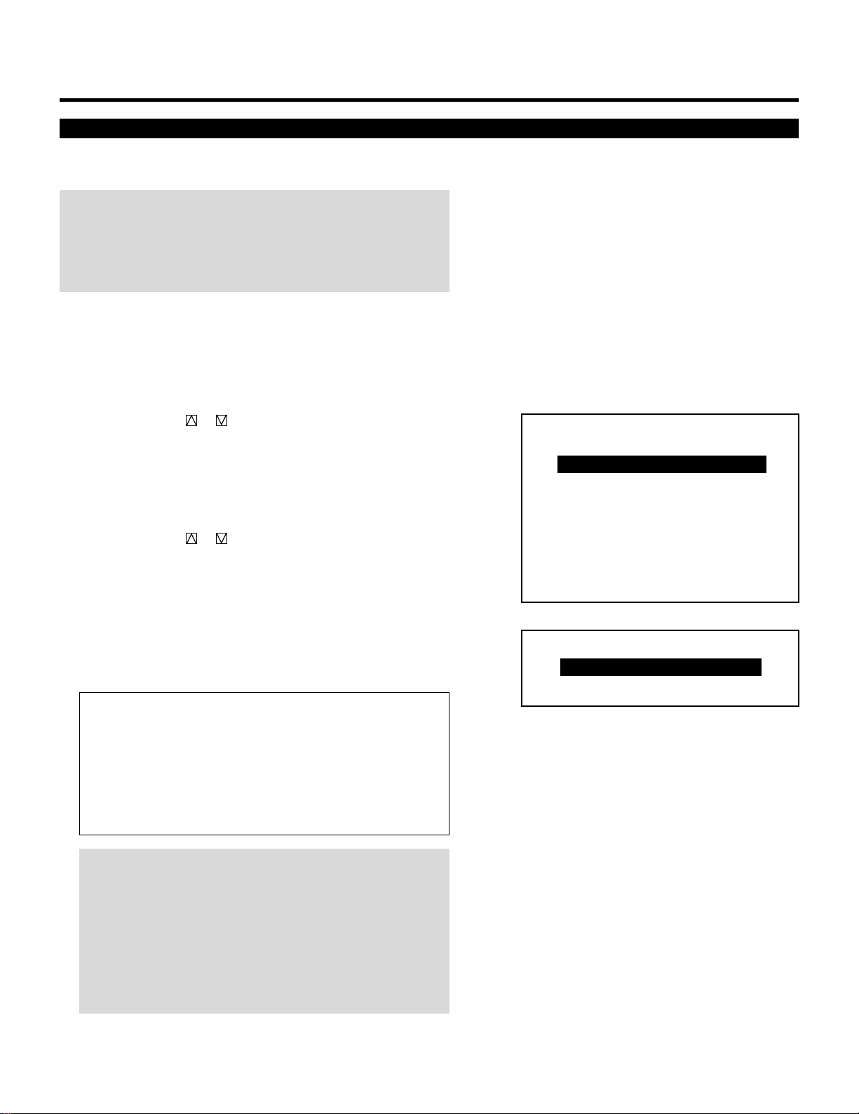
32
ADJUSTMENT
Electrical Focus Adjustment
Adjust the center focus and edge focus electrically to obtain the best
screen focus.
NOTE:
• The CENTER focus adjustment should be performed for each CRT
separately.
• Select the FOCUS test pattern using the TEST button on the full
function remote control.
Proceed as follows:
1 Press the ADJUST button to display the “ADJUST” menu.
• The projector may ask you to enter your passcode.
See page 52 for the explanation of the PASS CODE.
2 Use the CURSOR or button to highlight the “2/FOCUS”
line. Press ENTER to display the FOCUS menu. You can also
select the FOCUS menu directly by pressing the INPUT “2”
button.
• “6/R, G, B GAIN” is not included in stand alone adjust menu.
3 Use the CURSOR or button to highlight your preferred
adjustment item. Press ENTER to display the selected adjustment
screen.
• You can also select the adjustment screen directly by pressing
the INPUT “1” or “2” button.
• For edge focus, you can select either “EDGE ALL” or “EDGE
SEPA.” in the FOCUS EDGE mode of the OPTION menu.
(See page 89).
Items to select
• CENTER......... The focus adjustment for the center of the
screen
• EDGE ALL...... The focus adjustment for the edge area of the
screen (all CRTs)
• EDGE SEPA. .. The focus adjustment for the edge area of the
screen (each CRT)
NOTE:
• The adjustment screen can also be displayed by pressing the
FOCUS button on the full function remote control. The FOCUS
button will toggle between the CENTER and EDGE ALL/SEPA.
focus.
• The FOCUS CENTER adjustment screen can also be switched
directly to the FOCUS EDGE (ALL/SEPA.) adjustment screen
with CTL and CURSOR buttons and vice versa.
– ADJUST –
1 / SIGNAL ENTRY
2 / FOCUS
3 / ALIGNMENT
4 / CONVERGENCE
5 / WHITE BAL
6 / R,G,B GAIN
7 / HOUR METER
8 / PASSCODE
9 / OPTION
– FOCUS –
1 / CENTER
2 / EDGE ALL
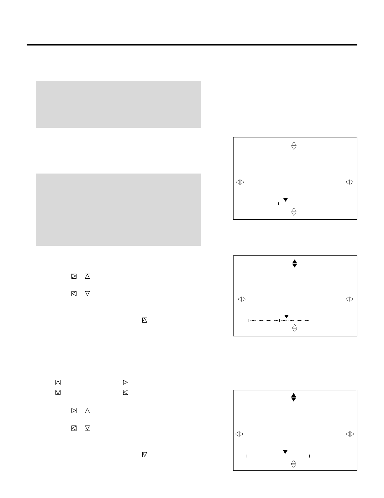
33
ADJUSTMENT
4 Press the R, G, and B button to project the CRT beam to be
adjusted.
• You can turn on or off each CRT beam (R, G, and B)separately.
NOTE:
• The CENTER and EDGE SEPA. focus adjustment should be
performed for each CRT separately.
• The EDGE ALL focus adjustment affects all the three CRTs at
the same time.
5 Hold down the CTL button then select the CRT you wish to
adjust with the R, G, and B button.
• The display of the corresponding CRT will change from one
CRT to another.
NOTE:
• You do not need to select the CRT color for the EDGE ALL
focus.
• Always be aware of what color the on-screen CRT display is
showing (R, G, B) when “CENTER” or “EDGE SEPA.” is
selected. If that color’s test pattern is turned off, any adjust-
ment to that color will display the “THIS COLOR IS NOT
APPLICABLE” message.
6 Use the CURSOR buttons to adjust the focus.
m When selecting “CENTER”
• Pressing the or button increases the control levels of the
center focus. (The gauge mark in the scale moves to the right.)
• Pressing the or button decreases the control levels of the
center focus. (The gauge mark in the scale moves to the left.)
To switch to the FOCUS EDGE mode:
press and hold CTL, then press CURSOR .
m When selecting “EDGE ALL”/”EDGE SEPA.”
• Press and hold the CTL button then press any one of the
CURSOR buttons to select the position to be adjusted. (The
marker on the selected side will turn to a solid color.)
CTL + .... U (Up) CTL + ..... R (Right)
CTL + .... D (Down) CTL + ..... L (Left)
Use the CURSOR buttons to adjust the focus.
• Pressing the or button increases the control levels of the
edge focus. (The gauge mark in the scale moves to the right.)
• Pressing the or button decreases the control levels of the
edge focus. (The gauge mark in the scale moves to the left.)
To switch to the FOCUS CENTER mode:
press and hold CTL, then press CURSOR . You need to press
them twice to change to the EDGE DOWN adjustment.
FOCUS
- CENTER -
CRT - R -
`10%
FOCUS
- EDGE ALL -
`10%
U
FOCUS
- EDGE SEPARATE -
CRT - R -
`10%
U
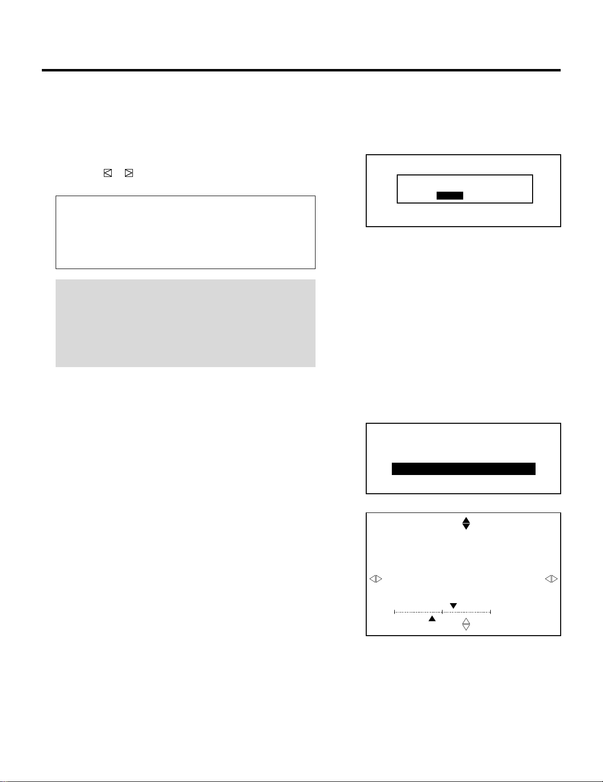
34
7 Repeat steps 4 to 6 for the other CRTs if necessary.
8 To end this adjustment, press the END button.
• Whenever the END button is pressed, the menu will sequence
in this order:
“FOCUS” menu → “ADJUST” menu → Source screen
• If the “RETURN USER MODE?” menu appears, use the
CURSOR or button to select either “YES” or “NO” and
then press ENTER. This will exit the ADJUST mode.
Items to select
• YES ......... When you try to enter the ADJUST mode the next
time, you will need to re-enter your passcode.
• NO........... When you try to enter the ADJUST mode the next
time, you will not need to re-enter your passcode.
NOTE: The center focus for the Blue CRT is pre-adjusted so that
the best white uniformity can be obtained at the gauge center
(0%). For this reason, it has been set at the factory to be
slightly out of focus.
Therefore you should not perform the center focus adjustment
to the Blue CRT with the remote control.
m ASTIG Adjustment
When ASTIG ADJUSTMENT in the OPTION menu is set to
ON, the focus menu is displayed.
Holding down CTL and then pressing FOCUS toggle between
the ASTIG CROSS and the ASTIG CORNER mode
To adjust ASTIG CROSS/CORNER:
1) Hold down CTL, then press FOCUS to select either ASTIG
CROSS or ASTIG CORNER.
First perform the ASTIG CROSS adjustment and then the
ASTIG CORNER adjustment.
• The test pattern automatically changes to the DOT
COARSE pattern.
2) Select the CRT you wish to adjust with R or G button.
• The blue CRT is not adjusted.
3) Press the R or G button to project the only CRT beam to be
adjusted.
• You can turn on or off each CRT beam (R, G, and B)
ADJUSTMENT
– FOCUS –
1 / CENTER
2 / EDGE ALL
3 / ASTIG CROSS
4 / ASTIG CORNER
RETURN USER MODE?
YES NO
FOCUS
- ASTIG CROSS -
CRT - R -
SCREEN - U -
60%HV
SK
40%
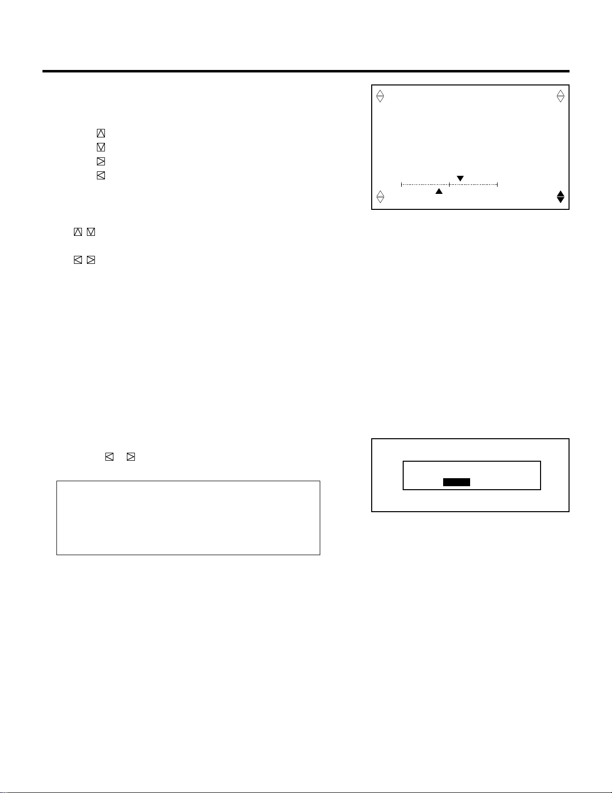
35
4) Press and hold the CTL button then press any one of the
CURSOR buttons to select the position to be adjusted. (The
marker on the selected side will turn to a solid color.)
CTL + ...... U (Up)
CTL + ...... D (Down)
CTL + ...... R (Right)
CTL + ...... L (Left)
5) Use the CURSOR buttons to adjust
.......... Corrects spindle-shape dot horizontally and
vertically
.......... Corrects spindle-shape dot diagonally
Adjust the dots on the selected side to the same shape as the
center dots.
6) Repeat steps 2) for the other CRTs.
7) To end this adjustment, press the END button.
• Whenever the END button is pressed, the menu will sequence
in this order:
“FOCUS” menu → “ADJUST” menu → Source screen
• If the “RETURN USER MODE?” menu appears, use the
CURSOR or button to select either “YES” or “NO” and
then press ENTER. This will exit the ADJUST mode.
Items to select
• YES ......... When you try to enter the ADJUST mode the next
time, you will need to re-enter your passcode.
• NO........... When you try to enter the ADJUST mode the next
time, you will not need to re-enter your passcode.
ADJUSTMENT
RETURN USER MODE?
YES NO
FOCUS
- ASTIG CORNER -
CRT - R -
SCREEN - DR -
60%
HV
SK
40%
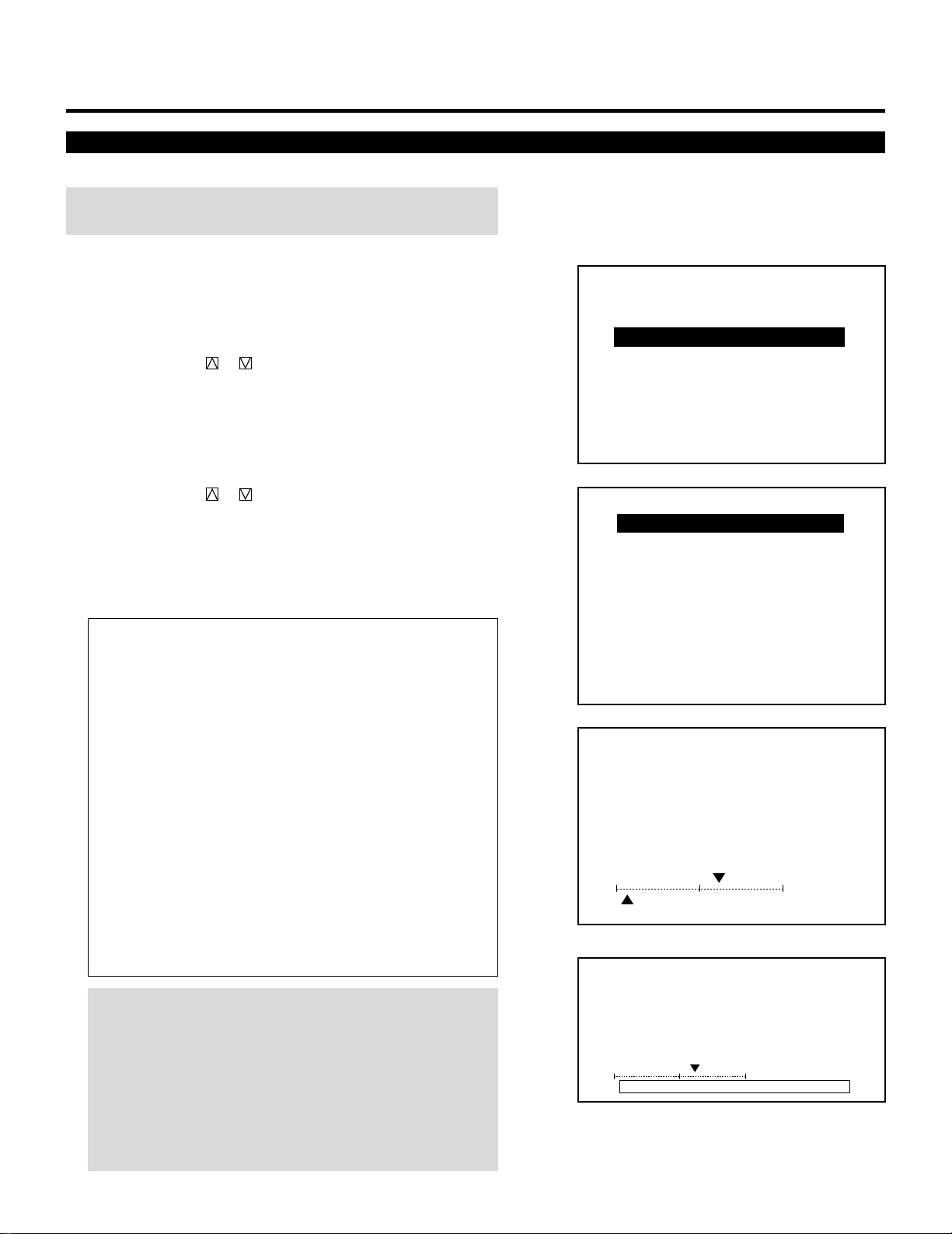
36
Alignment Adjustment
Correct the horizontal and vertical error for the projected image.
NOTE: Select the CROSS-COARSE test pattern using the TEST
button on the full function remote control.
Proceed as follows:
1 Press the ADJUST button to display the “ADJUST” menu.
• The projector may ask you to enter your passcode.
See page 52 for the explanation of the PASSCODE.
2 Use the CURSOR or button to highlight the “3/ALIGN-
MENT” line. Press ENTER to display the “ALIGNMENT”
menu. You can also select the “ALIGNMENT” menu directly by
pressing the INPUT “3” button.
• ”6/R, G, B GAIN” is not included in stand alone adjust menu.
3 Use the CURSOR or button to select the preferred item.
Press ENTER. You can also select the alignment item directly by
pressing an INPUT button.
• The selected adjustment screen will be displayed.
See page 38 and 39 for the explanation of the selected adjust-
ment.
Items to select
• TILT SKEW..........Adjusts the tilt and the skew
• BOW....................Adjusts the horizontal and vertical bow
• AMPLITUDE ........Adjusts the horizontal and vertical ampli-
tude of the projected image
• LINEARITY ..........Adjusts the horizontal and vertical linearity
• KEY-STONE.........Adjusts the horizontal and vertical keystone
• PIN-CUSHION .....Adjusts the horizontal and vertical pincush-
ion
• LINEAR-BAL........Adjusts the horizontal and vertical linearity
balance
• KEY-BALANCE.....Adjusts the horizontal and vertical keystone
tilt balance
• PIN-BALANCE .....Adjusts the horizontal and vertical pincush-
ion bow balance
• PHASE.................Adjusts the tilt and the cursor phase
NOTE: You can also select adjustments directly using buttons
on the full function remote control. If you are in the CONVER-
GENCE mode (see page 42), press and hold down the CTL
button then press the G button. This will bring you to the
ALIGNMENT adjustment screen. To select the “LINEAR-BAL”,
“KEY-BALANCE”, or “PIN-BALANCE” alignment, press and hold
down the CTL button then press the LINEAR,KEYSTN, or
PINCUS button respectively.
ADJUSTMENT
– ADJUST –
1 / SIGNAL ENTRY
2 / FOCUS
3 / ALIGNMENT
4 / CONVERGENCE
5 / WHITE BAL
6 / R,G,B GAIN
7 / HOUR METER
8 / PASSCODE
9 / OPTION
– ALIGNMENT –
1 / TILT,SKEW
2 / BOW
3 / AMPLITUDE
4 / LINEARITY
5 / KEY-STONE
6 / PIN-CUSHION
7 / LINEAR-BAL
8 / KEY-BALANCE
9 / PIN-BALANCE
0 / PHASE
ALIGNMENT
- TILT,SKEW -
`10%
H
190%V
ALIGNMENT
- TILT,SKEW -
`10%
H
ABNORMAL CORRECTION DATAV
During alignment or convergence adjustment, if the
projector acknowledges that your adjustment is overcor-
rected, the “ABNORMAL CORRECTION DATA” message
appears. The data is cancelled at that moment. If this
happens, reduce the total amount of the current adjust-
ment data.
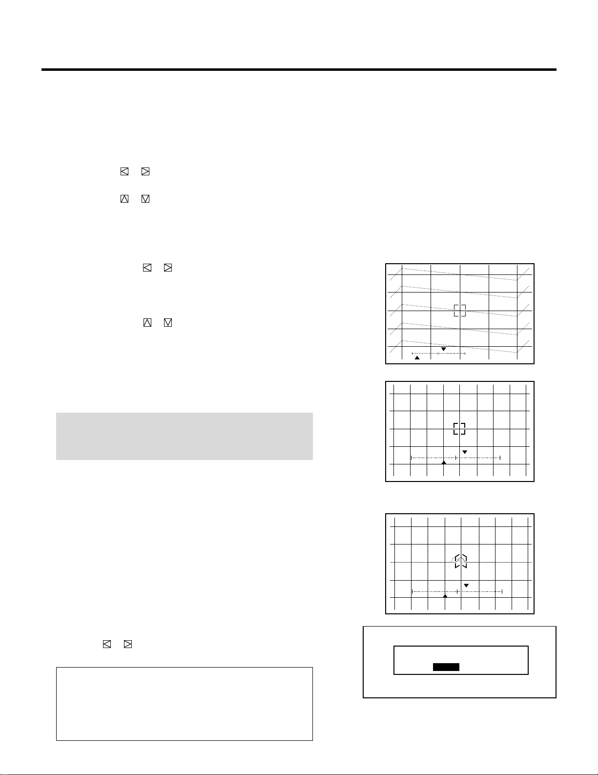
37
4 Press the R, G, and B buttons to display only the Green pattern.
• You can turn on or off each CRT beam (R, G or B) separately.
• To access the CONVERGENCE screen (see page 42), press and
hold down the CTL button then press the R or B button.
5 Use the CURSOR buttons to adjust the alignment of the pro-
jected pattern.
• The CURSOR or button increases or decreases the
horizontal level.
The CURSOR or button increases or decreases the vertical
level.
For “PHASE” adjustment, follow the instructions below.
m PHASE Adjustment
1) Use the CURSOR or button to adjust the tilt phase (for
horizontal line).
Adjust the pattern so the sharp turns at the left and right edges
in the diagonal lines are equal.
2) Use the CURSOR or button to adjust the cursor phase
(for vertical line).
Align the vertical center line of the point cursor with the
screen center.
(When the point Convergence Board is installed:)
3) Align the point peak with the screen center using CTL and
CURSOR buttons.
NOTE: Since the projector has been pre-adjusted for the optimal
phase adjustments at the factory, further adjustment should not
be required in normal operation.
6 To end this adjustment, press the END button.
• Whenever the END button is pressed, the menus will sequence
in this order:
“ALIGNMENT” menu → “ADJUST” menu → Source screen
• If the “RETURN USER MODE?” menu appears, use the
CURSOR or button to select either “YES” or “NO” and
then press ENTER. This will exit the ADJUST mode.
Items to select
• YES ......... When you try to enter the ADJUST mode again,
you will need to re-enter your passcode.
• NO........... When you try to enter the ADJUST mode again,
you will not need to re-enter your passcode.
ADJUSTMENT
RETURN USER MODE?
YES NO
PHASE
- TILT CURSOR -
T
C
`10%
132%
TILT PHASE
PHASE
- TILT CURSOR -
T
C
`10%
190%
PHASE
- TILT CURSOR -
T
C
`10%
132%
CURSOR PHASE
POINT PHASE (When installing the
Point Convergence board.)
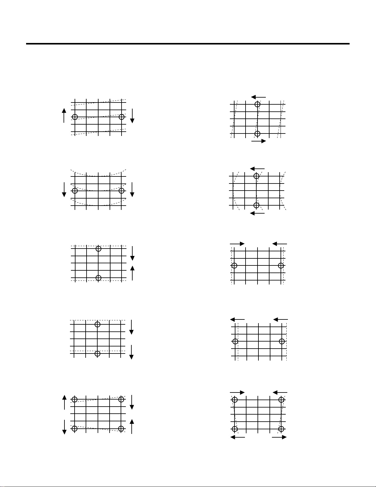
38
Alignment Adjustment Items
TILT
Adjust horizontal center line.
Vertical LINEARITY
Adjust top and bottom linearity.(Test pattern)
SKEW
Adjust vertical center line.
Horizontal LINEARITY
Adjust left and right linearity.(Test pattern)
Vertical BOW
Adjust horizontal center line bow.
Horizontal BOW
Adjust vertical center line bow.
Vertical AMPLITUDE
Adjust vertical height of image.
Horizontal AMPLITUDE
Adjust horizontal size of image.
Vertical KEYSTONE
Adjust top and bottom keystone error.
Horizontal KEYSTONE
Adjust left and right keystone error.
ADJUSTMENT
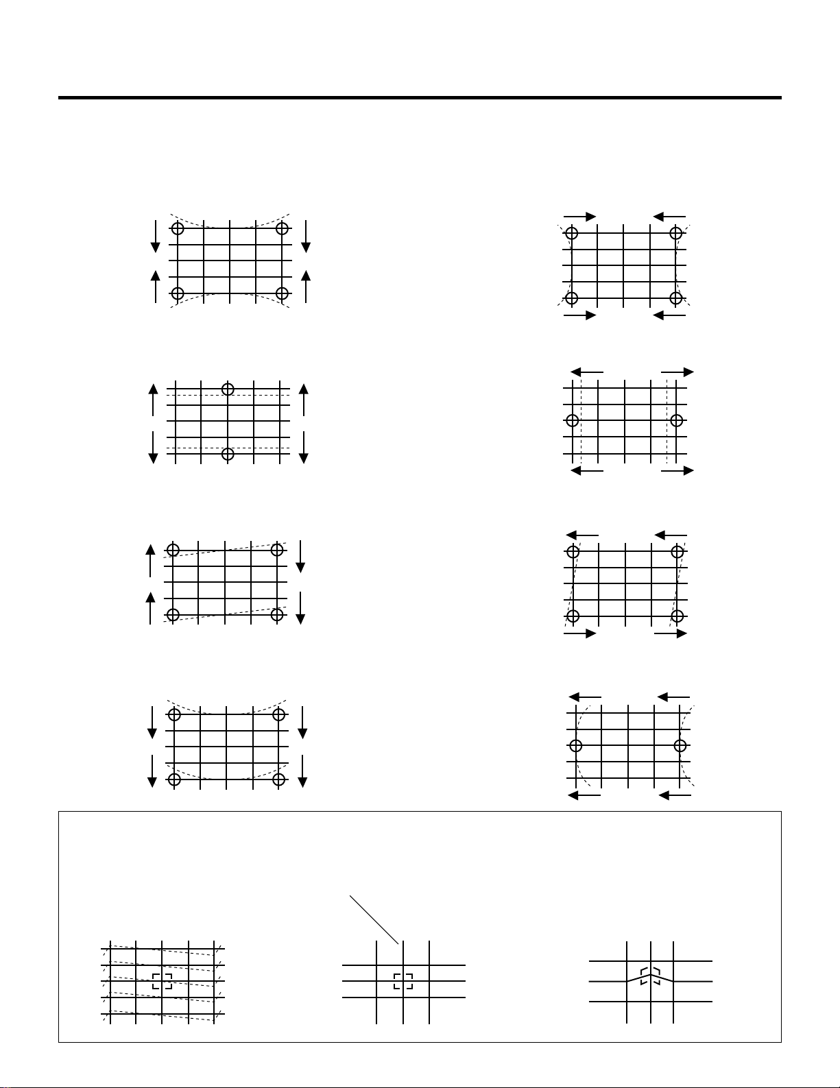
39
Alignment Adjustment Items
Vertical PINCUSHION
Equalize top and bottom pincushion error.
Horizontal PINCUSHION
Equalize left and right pincushion error.
ADJUSTMENT
Vertical PIN-BALANCE
Equalize top and bottom pincushion balance error.
Horizontal PIN-BALANCE
Equalize left and right pincushion balance error.
Vertical KEY-BALANCE
Equalize top and bottom keystone balance error.
Horizontal KEY-BALANCE
Equalize left and right keystone balance error.
Vertical LINEAR-BALANCE
Equalize top and bottom linearity balance error.
Horizontal LINEAR-BALANCE
Equalize left and right linearity balance error.
TILT PHASE
Adjust the pattern so the sharp turns
at the left and right edges in the
diagonal lines are equal.
POINT PHASE
When the Point Convergence board is
installed;
Align the point peak with the vertical
center line of the point cursor.
CURSOR PHASE
Align the vertical center line of the point
cursor with the screen center.
<Screen center>
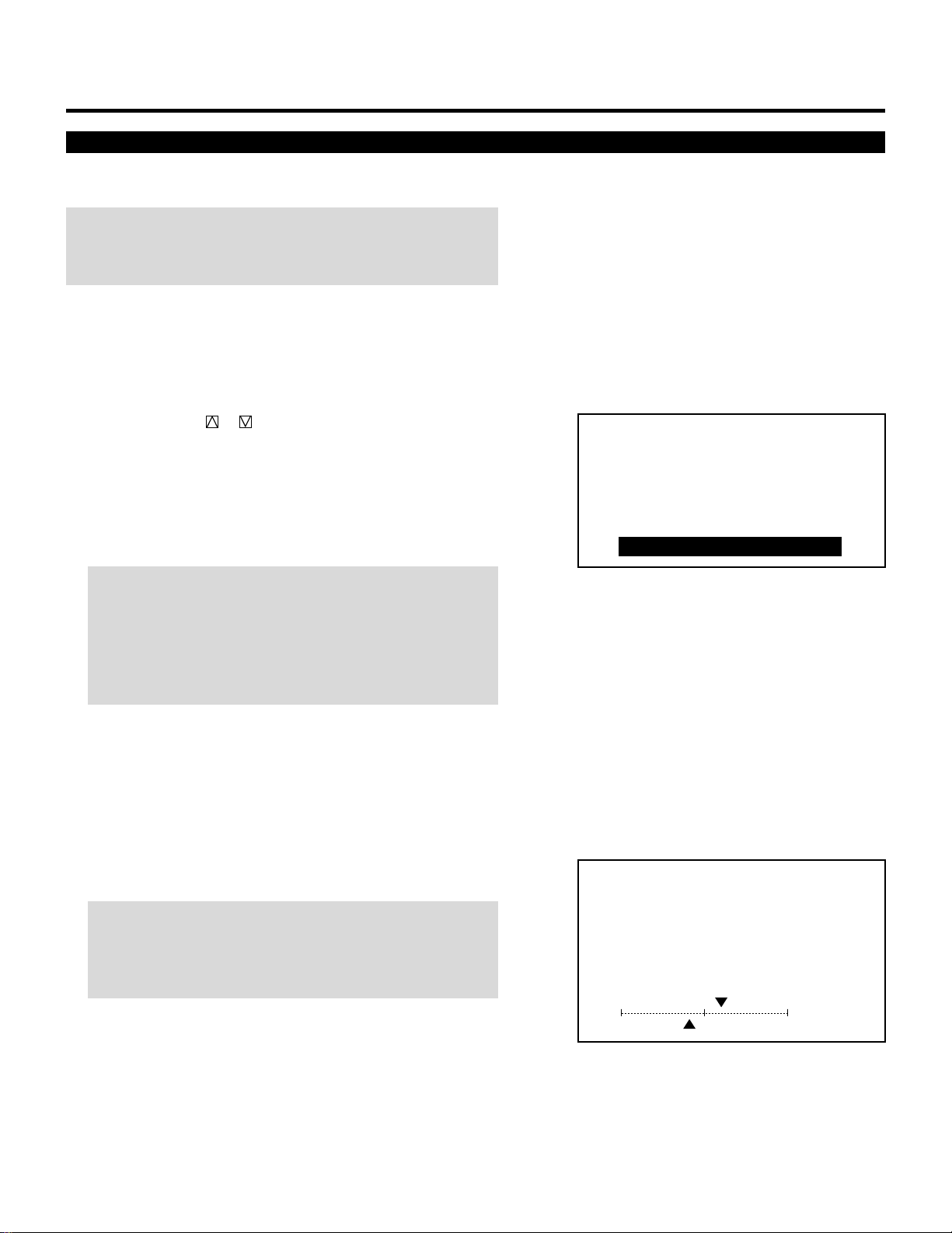
40
ADJUSTMENT
Static Convergence Adjustment
Adjust the red and blue CRT images to position them over the green
test pattern (center portion only).
NOTE: The static convergence adjustment should be performed for
each CRT (R and B) separately. Carry out the adjustment after
displaying an active image for 20 minutes or more.
Proceed as follows:
1 Press the OPERATE button.
• The “OPERATE” menu is displayed.
2 Use the CURSOR or button to highlight the “6/STATIC”
line. Press ENTER to display the STATIC adjustment. You can
also select the STATIC adjustment screen directly by pressing
the INPUT “6” button.
• When the projector is used in stand alone operation, the fifth
item is “STATIC”.
• The CROSS-HAIR test pattern will be automatically displayed.
NOTE: When you are in the ADJUST mode, selecting the
STATIC mode will not automatically select the CROSS-HAIR test
pattern. Reselect the pattern using the TEST button.
NOTE: The “STATIC” adjustment can be also displayed by
pressing the STATIC button on the user or full function remote
control.
3 Press the R or B button to display the pattern to be aligned with
the Green pattern.
• You can turn on or off each CRT beam (R and B) separately.
4 Hold down the CTL button then select the CRT you wish to
adjust with the R and B buttons.
NOTE: Always be aware of what color the on-screen CRT
display is showing (R, G, B). If that color’s test pattern is turned
off, any adjustment to that color will display the “THIS COLOR
IS NOT APPLICABLE” message.
– OPERATE –
1 / PICTURE
2 / POSITION
3 / SOUND
4 / INPUT SELECT
5 / SOURCE INFO
6 / STATIC
CONVERGENCE
- STATIC -
`10%
CRT - R -
110%
H
V

41
ADJUSTMENT
5 Align the center of the Red or the Blue pattern with the center of
the Green pattern (reference color) using the CURSOR buttons.
• The CURSOR or button moves the pattern left or right.
The CURSOR or button moves the pattern up or down.
6 Repeat steps 3 to 5 for the other CRTs if necessary.
7 To end this adjustment, press the END button.
• Whenever the END button is pressed, the menus will sequence
in this order:
“OPERATE” menu → Source screen
Red or Blue
Green
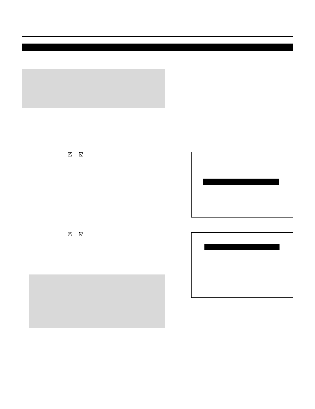
42
ADJUSTMENT
Corrects the horizontal and vertical error for each color and align the
red and blue to the green.
NOTE:
• The dynamic convergence adjustment should be performed for
each CRT (R and B) separately.
• Select the CROSS-COARSE test pattern using the TEST button on
the full function remote control.
Proceed as follows:
1 Press the ADJUST button to display the “ADJUST” menu.
• The projector may ask you to enter your passcode.
See page 52 for the explanation of the PASSCODE.
2 Use the CURSOR or button to highlight the “4/CONVER-
GENCE” line. Press ENTER to display the “CONVERGENCE”
menu. You can also select the “CONVERGENCE” menu directly
by pressing the INPUT “4” button.
• ”6/R, G, B GAIN” is not included in stand alone adjust menu.
3 Use the CURSOR or button to select the preferred item and
then press ENTER. You can also select directly the dynamic
convergence item by pressing an INPUT button.
• The selected adjustment will be displayed.
See pages 44 and 45 for the explanation of the selected adjust-
ment.
NOTE: You can also select adjustments directly using buttons
on the full function remote control. If you are in the ALIGN-
MENT mode (see page 36), press and hold down the CTL
button then press the R or B button. This will bring you to the
CONVERGENCE adjustment screen. To select “LINEAR-BAL”
convergence, press and hold down the CTL button then press
the LINEAR button.
4 Press the R or B button to display the CRT beam to be aligned
with the Green pattern.
• You can turn on or off each CRT beam (R and B) separately.
Dynamic Convergence Adjustment
– ADJUST –
1 / SIGNAL ENTRY
2 / FOCUS
3 / ALIGNMENT
4 / CONVERGENCE
5 / WHITE BAL
6 / R,G,B GAIN
7 / HOUR METER
8 / PASSCODE
9 / OPTION
– CONVERGENCE –
1 / TILT,SKEW
2 / BOW
3 / AMPLITUDE
4 / LINEARITY
5 / KEY-STONE
6 / PIN-CUSHION
7 / LINEAR-BAL
8 / POINT
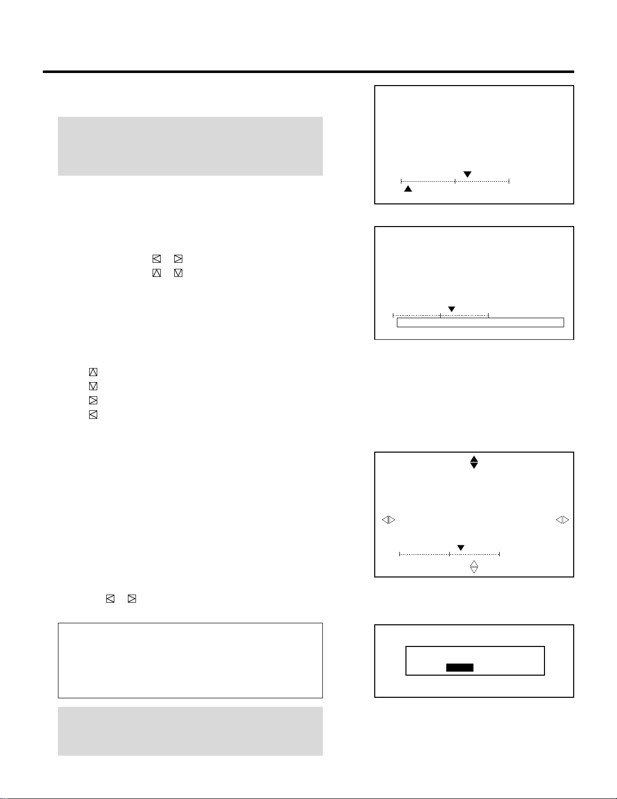
43
ADJUSTMENT
During alignment or convergence adjustment, if the projector
acknowledges that your adjustment is overcorrected, the
“ABNORMAL CORRECTION DATA” message appears. The data
is cancelled at that moment. If this happens, reduce the total
amount of the current adjustment data.
RETURN USER MODE?
YES NO
5Hold down the CTL button then select the CRT you wish to
adjust with the R and B buttons.
NOTE: Always be aware of what color the on-screen CRT
display is showing (R, B). If that color’s test pattern is turned
off, any adjustment to that color displays the “THIS COLOR IS
NOT APPLICABLE” message.
• To access the ALIGNMENT screen (see page 36), press and
hold down the CTL button then press the G button.
6 Align the Red or the Blue pattern with the Green pattern using
the CURSOR buttons.
• The CURSOR button or increases or decreases H level.
The CURSOR button or increases or decreases V level.
The following are the description of the KEYSTONE, PIN-
CUSHION, and LINEAR-BALANCE adjustments.
m KEYSTONE, PINCUSHION, and LINEAR-BALANCE
Adjustments
• Press and hold the CTL button then press any one of the
CURSOR buttons to select the position to be adjusted.
CTL + .... U (Up)
CTL + .... D (Down)
CTL + .... R (Right)
CTL + .... L (Left)
• Use the CURSOR buttons to correct the error.
7 Repeat steps 3 to 6 for the other CRTs if necessary.
• Pressing the END button will bring you to the “CONVER-
GENCE” menu.
8 To exit, press END to display the “STORE?” menu.
• Whenever the END button is pressed, the menus will sequence
in this order:
“CONVERGENCE” menu → “ADJUST” menu → Source
screen
• If the “RETURN USER MODE?” menu appears, use the
CURSOR or button to select either “YES” or “NO” and
then press ENTER. This will exit the ADJUST mode.
Items to select
• YES ......... When you try to enter the ADJUST mode again,
you will need to re-enter your passcode.
• NO........... When you try to enter the ADJUST mode again,
you will not need to re-enter your passcode.
NOTE: Adjusting the dynamic convergence may cause the static
convergence settings to change. If this happens, adjust the
static convergence again.
CONVERGENCE
- TILT,SKEW -
CRT - R -
`10%
H
190%V
CONVERGENCE
- TILT,SKEW -
CRT - R -
`10%
H
ABNORMAL CORRECTION DATAV
CONVERGENCE
- KEY - STONE -
CRT - R -
`10%
U
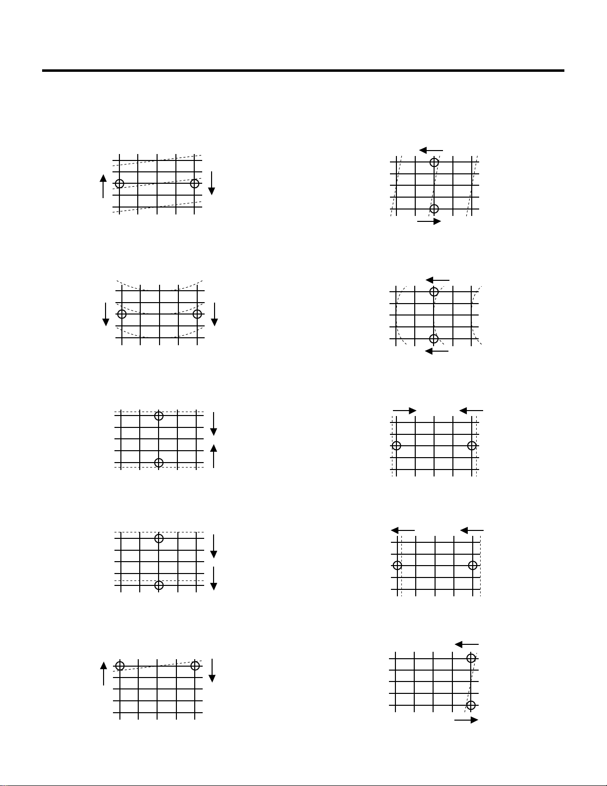
44
Convergence Adjustment Items
TILT
Adjust horizontal center line.
SKEW
Adjust vertical center line.
When R(Right) is selected
KEYSTONE
Adjust the selected part.
When U(Up) is selected
Horizontal LINEARITY
Adjust left and right linearity.
Vertical LINEARITY
Adjust top and bottom linearity.
Horizontal AMPLITUDE
Adjust left and right width.
Vertical AMPLITUDE
Adjust top and bottom height.
Horizontal BOW
Adjust vertical center line bow.
Vertical BOW
Adjust horizontal center line bow.
ADJUSTMENT
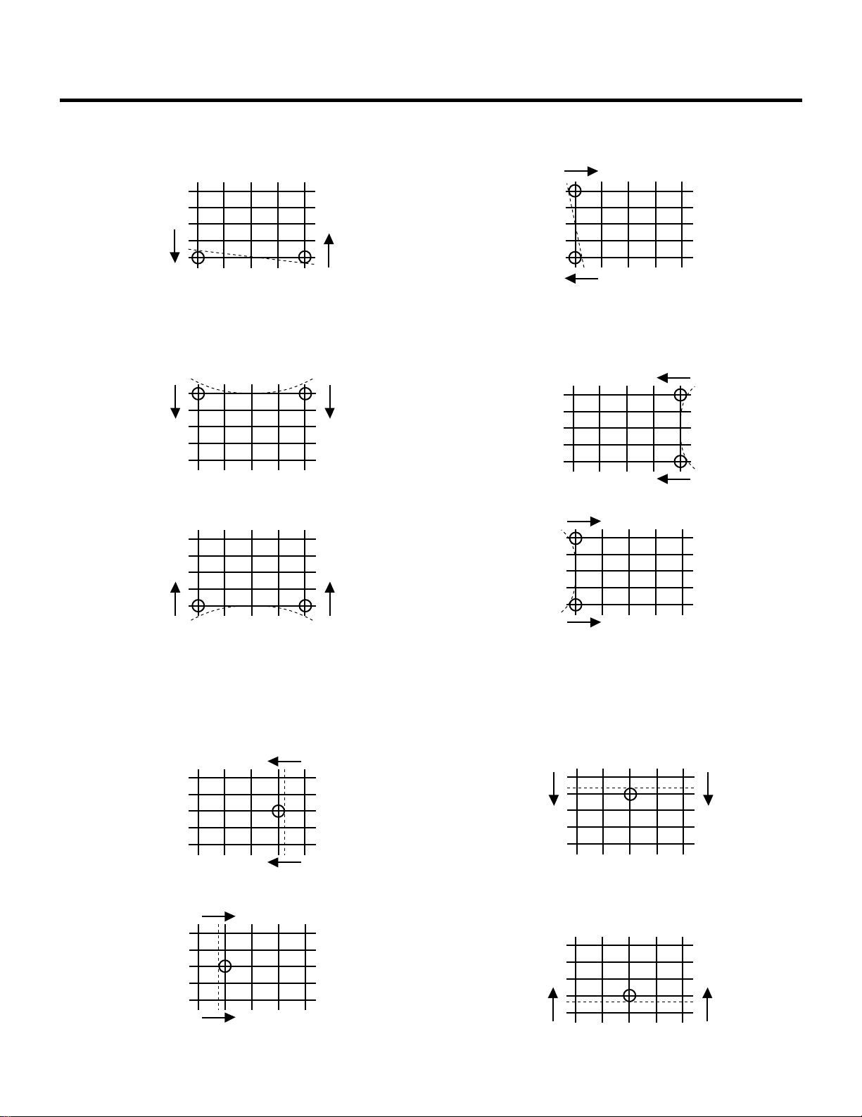
45
When L(Left) is selected
When D(Down) is selected
PINCUSHION
LINEAR-BALANCE
Adjust the selected part.
When U(Up) is selected
When R(Right) is selected
When L(Left) is selected
When D(Down) is selected
When D(Down) is selectedWhen L(Left) is selected
When R(Right) is selected When U(Up) is selected
ADJUSTMENT
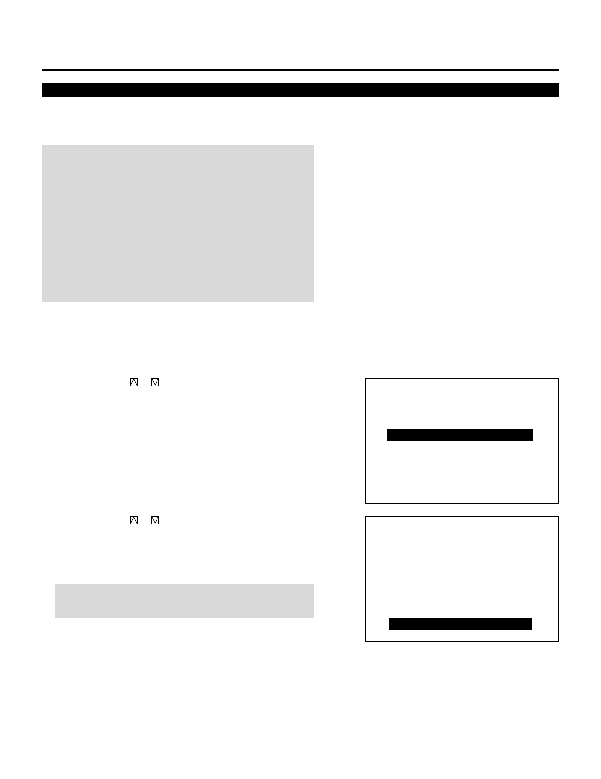
46
Point Convergence Adjustment
After you have aligned all three colors with the static and dynamic
adjustments, use the point convergence to touch up any mis-conver-
gence that would be difficult to do by way of dynamic adjustments.
NOTE:
• Since the point convergence function is optional for the MultiSync
6PG XTRA, you need to install the Point Convergence board and
set to activate the point convergence for the MultiSync 6PG XTRA.
See page 66 for this procedure.
• Point convergence should only be done as a last resort. Use the
dynamic geometry controls to correct any large convergence
errors. Over adjusting point convergence may degrade the
projector’s performance.
• Point convergence should only be done for the red and blue test
patterns, never the green.
Proceed as follows:
1 Press the ADJUST button to display the “ADJUST” menu.
• The projector may ask you to enter your passcode.
See page 52 for the explanation of the PASSCODE.
2 Use the CURSOR or button to highlight the “4/CONVER-
GENCE” line. Press ENTER to display the “CONVERGENCE”
menu. You can also select the “CONVERGENCE” menu directly
by pressing the INPUT “4” button.
• ”6/R, G, B GAIN” is not included in stand alone adjust menu.
3 Use the CURSOR or button to select the “8/POINT” line.
Press ENTER. You can also select directly the point convergence
by pressing the INPUT “8” button.
• The CROSS-COARSE test pattern will be automatically
displayed and the point adjustment will be displayed.
NOTE: The “POINT” adjustment can be also displayed by
pressing the POINT button on the full function remote control.
4 Press the R or B button to display the CRT to be aligned with the
Green pattern.
• You can turn on or off each CRT beam (R, G and B) separately.
ADJUSTMENT
– ADJUST –
1 / SIGNAL ENTRY
2 / FOCUS
3 / ALIGNMENT
4 / CONVERGENCE
5 / WHITE BAL
6 / R,G,B GAIN
7 / HOUR METER
8 / PASSCODE
9 / OPTION
– CONVERGENCE –
1 / TILT,SKEW
2 / BOW
3 / AMPLITUDE
4 / LINEARITY
5 / KEY-STONE
6 / PIN-CUSHION
7 / LINEAR-BAL
8 / POINT
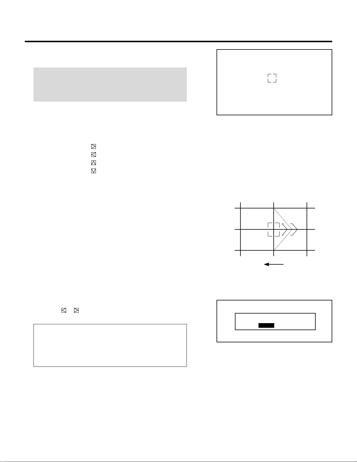
47
ADJUSTMENT
5 Hold down the CTL button then select the CRT you wish to
adjust with the R and B buttons.
NOTE: Always be aware of what color the on-screen CRT
display is showing (R, G, B). If that color’s test pattern is turned
off, any adjustment to that color displays the “THIS COLOR IS
NOT APPLICABLE” message.
6 Use the CURSOR buttons to move the cursor to the point to be
adjusted.
• Pressing the CURSOR button moves the cursor to the right.
Pressing the CURSOR button moves the cursor to the left.
Pressing the CURSOR button moves the cursor to the top.
Pressing the CURSOR button moves the cursor to the
bottom.
7 Hold down the CTL button then use the CURSOR buttons to
align the Red or Blue pattern with the Green pattern.
8 Repeat steps 4 to 7 for the other CRTs if necessary.
9 To end this adjustment, press END.
• Whenever END is pressed, the menus will sequence in this
order:
“CONVERGENCE” menu → “ADJUST” menu → Source
screen
• If the “RETURN USER MODE?” menu appears, use the
CURSOR or button to select either “YES” or “NO” and
then press ENTER. This will exit the ADJUST mode.
Items to select
• YES ......... When you try to enter the ADJUST mode again,
you will need to re-enter your passcode.
• NO........... When you try to enter the ADJUST mode again,
you will not need to re-enter your passcode.
RETURN USER MODE?
YES NO
CONVERGENCE
-POINT-
CRT - R -
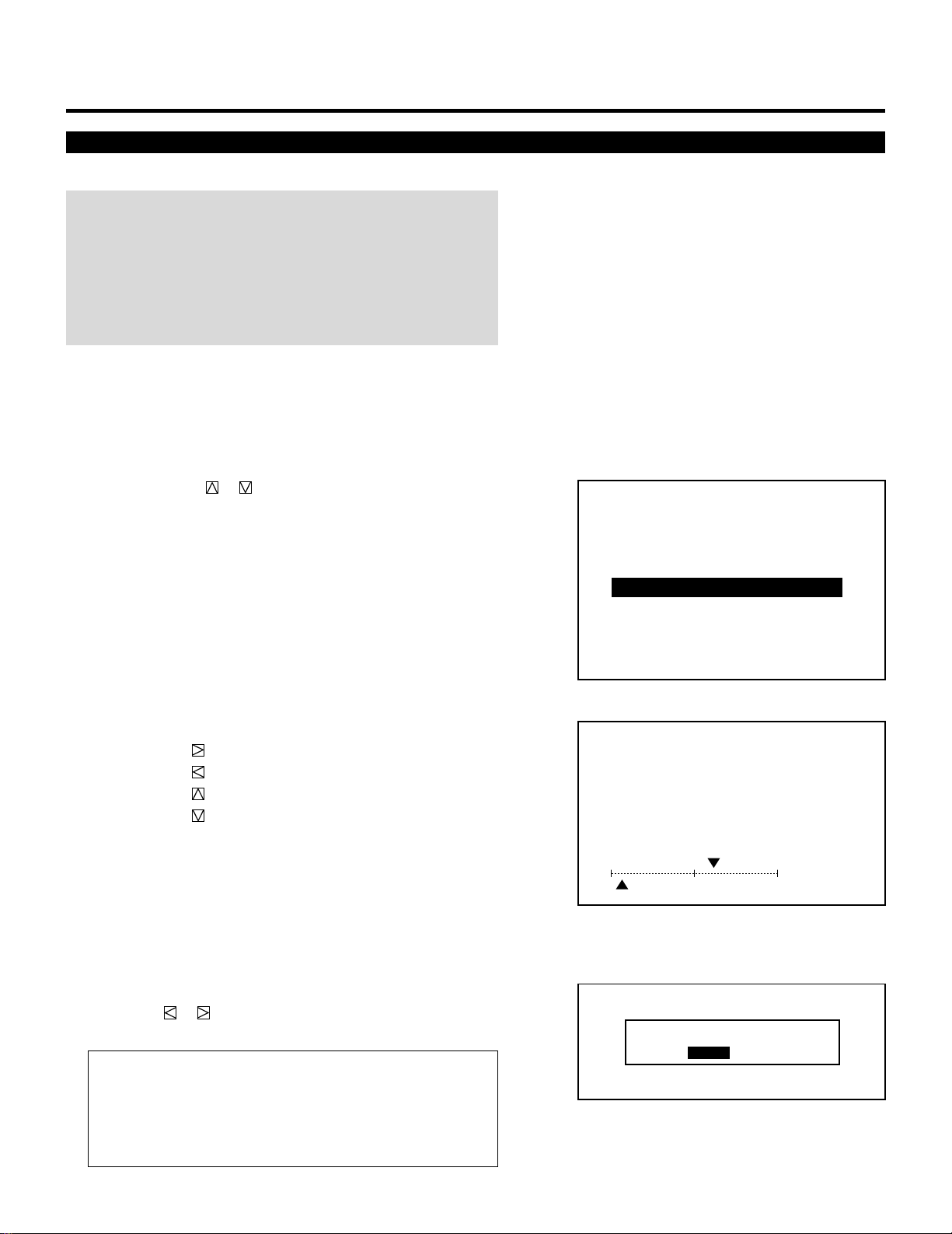
48
ADJUSTMENT
Adjusts the white balance.
NOTE:
• When you are in the white balance adjustment mode, all the CRTs
will be in use. The white balance adjustment should be performed
for each CRT (R, G, and B) separately. The CRT beam cannot be
cut-off.
• Select the WHITE-WINDOW pattern using the TEST button on the
full function remote control.
Proceed as follows:
1 Press the ADJUST button to display the “ADJUST” menu.
• The projector may ask you to enter your passcode.
See page 52 for the explanation of the PASSCODE.
2 Use the CURSOR or button to highlight the “5/WHITE-
BAL” line. Press ENTER to switch to the “WHITE BALANCE”
adjustment. You can also select the “WHITE BALANCE”
adjustment directly by pressing the INPUT “5” button.
• The “WHITE BALANCE” adjustment can be also displayed by
using the KELVIN button on the full function remote control.
• “6/R, G, B GAIN” is not included in stand alone adjust menu.
3 Hold down the CTL button then select the CRT you wish to
adjust with the R, G and B buttons.
4 Use the CURSOR buttons to adjust the white and the black level.
• The CURSOR button increases the white level.
The CURSOR button decreases the white level.
The CURSOR button increases the black level.
The CURSOR button decreases the black level.
5 Repeat steps 3 to 4 for the other CRTs if necessary.
6 To end this adjustment, press the END button.
• Whenever the END button is pressed, the menus will sequence
in this order.
“ADJUST” menu → Source screen
• If the “RETURN USER MODE?” menu appears, use the
CURSOR or button to select either “YES” or “NO” and
then press ENTER. This will exit the ADJUST mode.
Items to select
• YES ......... When you try to enter the ADJUST mode again,
you will need to re-enter your passcode.
• NO........... When you try to enter the ADJUST mode again,
you will not need to re-enter your passcode.
White Balance Adjustment
– ADJUST –
1 / SIGNAL ENTRY
2 / FOCUS
3 / ALIGNMENT
4 / CONVERGENCE
5 / WHITE BAL
6 / R,G,B GAIN
7 / HOUR METER
8 / PASSCODE
9 / OPTION
WHITE BALANCE
CRT - R -
60%
W
10%B
RETURN USER MODE?
YES NO
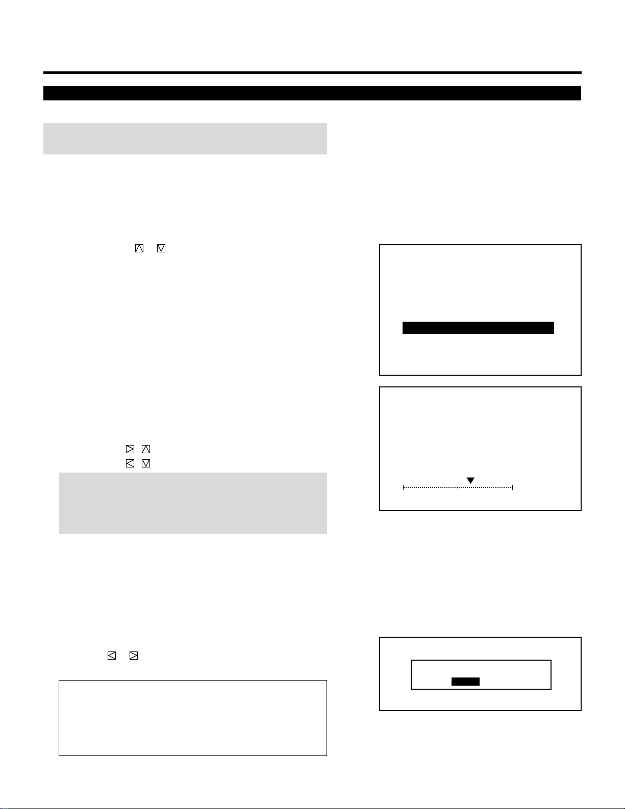
49
ADJUSTMENT
R, G, and B Gain Adjustment
Adjusts the input level of the signal.
NOTE: This adjustment works only with the ISS-6010/ISS-6010G
Switcher.
Proceed as follows:
1 Press the ADJUST button to display the “ADJUST” menu.
• The projector may ask you to enter your passcode.
See page 52 for the explanation of the PASSCODE.
2 Use the CURSOR or button to highlight the “6/R, G, B
GAIN” line. Press ENTER to display the “R, G, B GAIN”
adjustment screen. You can also select the “R, G, B GAIN”
adjustment screen directly by pressing the INPUT “6” button.
3 Hold down the CTL button then select the CRT you wish to
adjust with the R, G, and B buttons.
4 Use the CURSOR buttons to adjust the level of the input signal.
• The CURSOR , button increases the input level.
• The CURSOR , button decreases the input level.
NOTE: Connect the projector and the Switcher with a oscillo-
scope, then adjust the CURSOR buttons to obtain a value of
0.7Vp-p of the projector input level or the Switcher output level
on the oscilloscope.
5 Repeat steps 3 and 4 for other input signals if necessary.
6 To end this adjustment, press END.
• Whenever the END button is pressed, the menus will sequence
in this order:
“ADJUST” menu → Source screen
• If the “RETURN USER MODE?” menu appears, use the
CURSOR or button to select either “YES” or “NO” and
then press ENTER. This will exit the ADJUST mode.
Items to select
• YES ......... When you try to enter the ADJUST mode again,
you will need to re-enter your passcode.
• NO........... When you try to enter the ADJUST mode again,
you will not need to re-enter your passcode.
– ADJUST –
1 / SIGNAL ENTRY
2 / FOCUS
3 / ALIGNMENT
4 / CONVERGENCE
5 / WHITE BAL
6 / R,G,B GAIN
7 / HOUR METER
8 / PASSCODE
9 / OPTION
RETURN USER MODE?
YES NO
R,G,B GAIN
CRT - R -
60%

50
ADJUSTMENT
Checking and Setting the Running Time
The projector will give you the amount of operating time.
Proceed a follows:
1 Press the ADJUST button to display the “ADJUST” menu.
• The projector may ask you to enter your passcode.
See page 52 for the explanation of the PASSCODE.
2 Use the CURSOR or button to highlight the “7/HOUR
METER” line. Press ENTER to display the “HOUR METER”
screen. You can also select the “HOUR METER” screen directly
by pressing the INPUT “7” button.
• The sixth item is “6/HOUR METER” in stand alone adjust
menu.
Items to select
• PJ RUNNING TIME
The amount of operating time of the projector.
• CRT RUNNING TIME
The amount of operating time of CRT.
• USER PJ RUNNING TIME
The amount of operating time of the projector. User resetable.
• USER CRT RUNNING TIME
The amount of operating time of CRT. User resetable.
How to reset the user projector or CRT running time:
1) Use the CURSOR buttons to select the item and then press
ENTER.
• The “USER PJ RUNNING TIME RESET?” or “USER
CRT RUNNING TIME RESET?” menu is displayed.
2) Use the CURSOR or button to select either “YES” or
“NO” and then press ENTER.
Items to select
• YES ......... The time will be reset
• NO........... The time will not be reset
• The display will be returned to the “HOUR METER” screen.
– ADJUST –
1 / SIGNAL ENTRY
2 / FOCUS
3 / ALIGNMENT
4 / CONVERGENCE
5 / WHITE BAL
6 / R,G,B GAIN
7 / HOUR METER
8 / PASSCODE
9 / OPTION
USER PJ RUNNING TIME RESET?
YES NO
HOUR METER
PJ RUNNING TIME
CRT RUNNING TIME
USER PJ RUNNING TIME
USER CRT RUNNING TIME
∗∗∗∗ ∗∗
HM
∗∗∗∗ ∗∗
HM
∗∗∗∗ ∗∗
HM
∗∗∗∗ ∗∗
HM

51
ADJUSTMENT
3 To exit the HOUR METER display, press END.
• Whenever the END button is pressed, the menus will sequence
in this order:
“ADJUST” menu → Source screen
• If the “RETURN USER MODE?” menu appears, use the
CURSOR or button to select either “YES” or “NO” and
then press ENTER. This will exit the ADJUST mode.
Items to select
• YES ......... When you try to enter the ADJUST mode again,
you will need to re-enter your passcode.
• NO........... When you try to enter the ADJUST mode again,
you will not need to re-enter your passcode.
RETURN USER MODE?
YES NO

59
123456
12345
6
12345
6
12345
6
12345
6
12345
6
123456
SETTING.
Displaying the Various Setting Features
You can view some of the setting features and check to make sure
that the settings are appropriate.
To display setting features on the screen, hold down CTL and press
INFO.
To eliminate the display, press END.
The parameters cannot be changed on the SETTING VIEW screen
shown on the right.
For changing parameters of the setting features, refer to the follow-
ing pages.
AUTO POWER ON MODE
SETTING VIEW
INACTIVE
WARM-UP MODE INACTIVE
AUTOMATIC DATA STORE
PHOSPHOR SAVER OFF
SIGNAL SWITCHING
SOUND
DISABLE
MUTE ON
PICTURE
MUTE ON
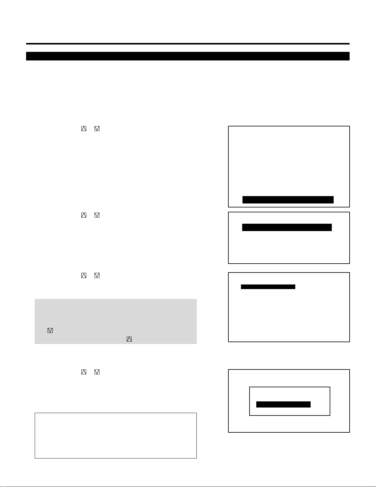
60
Connecting to the Switcher
This setting explains how the projector is used with the ISS-6010/
ISS-6010G Switcher.
1 Press the ADJUST button to display the “ADJUST” menu.
• The projector may ask you to enter your passcode.
See page 52 for the explanation of the PASSCODE.
2 Use the CURSOR or button to highlight the “9/OPTION”
line. Press ENTER to display the “OPTION” menu. You can also
select the “OPTION” menu directly by pressing the INPUT “9”
button.
• The eighth item is “8/OPTION” in stand alone adjust menu.
3 Use the CURSOR or button to highlight the “1/SETTING
MODE” line. Press ENTER to display the “SETTING MODE”
menu. You can also select the “SETTING MODE” menu directly
by pressing the INPUT “1” button.
4 Use the CURSOR or button to select the “CONNECT
CONDITION” item, then press ENTER to display the “CON-
NECT CONDITION” menu.
NOTE: The SETTING MODE has three menus. The “CONNECT
CONDITION” item is on the first menu (P01). To access P02 or
P03 from P01, press and hold down the CTL button then press
the button; to return to P01 from P02 or P03, press and hold
down the CTL button then press the button.
5 Use the CURSOR or button to select your desired connec-
tion condition of Switcher and press ENTER.
• The “RE-START ?” prompt is displayed after setting of the
connection condition is modified from the current status to your
desired condition.
Items to select
• STAND ALONE ....The projector used in stand alone operation.
• SW 1 LEVEL ........The projector used with one Switcher.
• SW 2 LEVEL ........The projector used with two or more
Switchers.
SETTING
– ADJUST –
1 / SIGNAL ENTRY
2 / FOCUS
3 / ALIGNMENT
4 / CONVERGENCE
5 / WHITE BAL
6 / R,G,B GAIN
7 / HOUR METER
8 / PASSCODE
9 / OPTION
– OPTION –
1 / SETTING MODE
2 / MENU MODE
3 / SEQUENCER
4 / PJ ADDRESS
5 / VERSION
P01
CONNECT CONDITION
OPTION – SETTING MODE –
STANDALONE
ASTIG OUTPUT CEILING
FRONT
DEGAUSS
POINT CONVERGENCE ENABLE
S-VIDEO MODE SELECT S2
VIDEO MODE SELECT AUTO
STANDALONE
SW1 LEVEL
SW2 LEVEL
CONNECT CONDITION
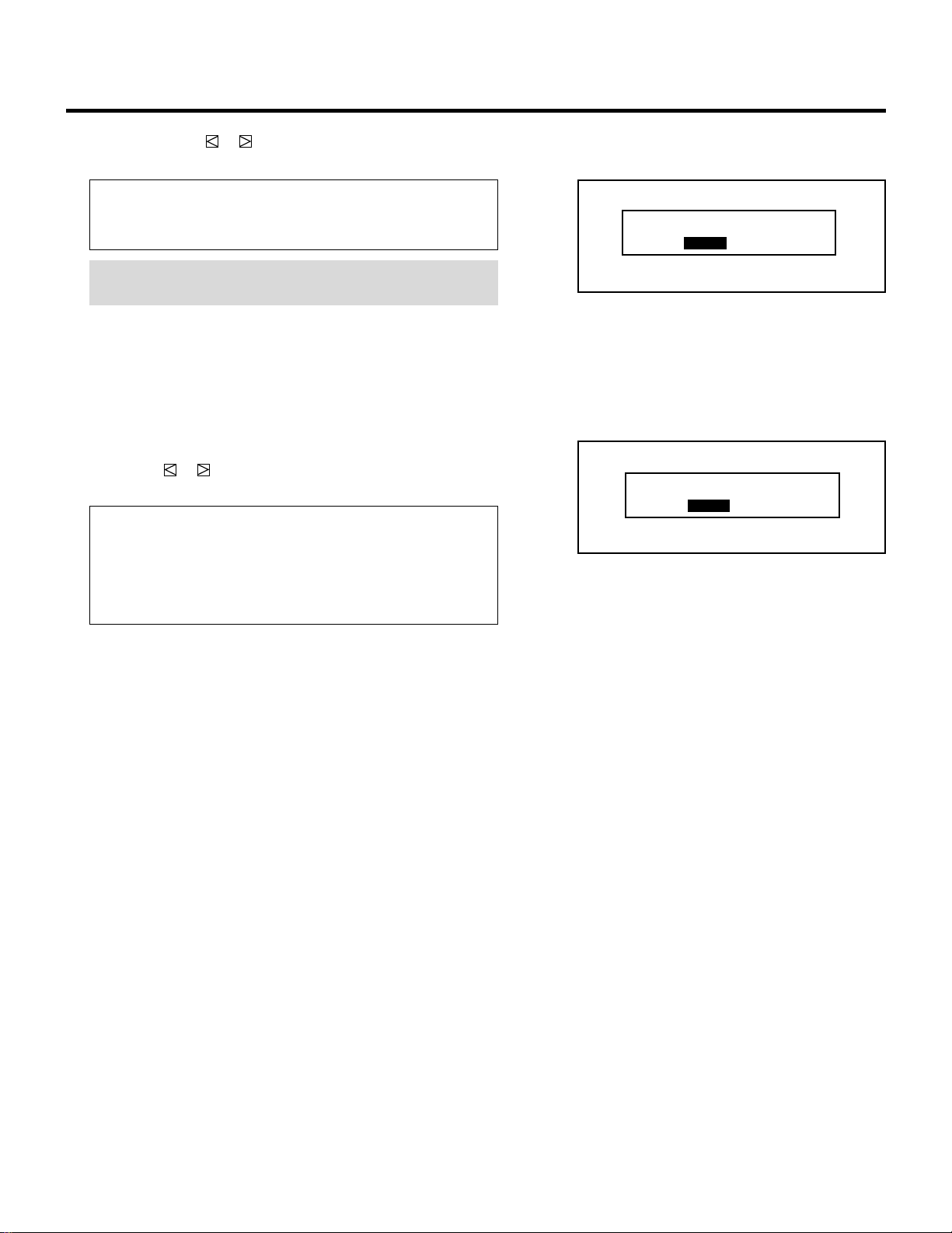
61
6 Use the CURSOR or button to select either “YES” or “NO”
and press ENTER.
Items to select
• YES ......... Restart the projector.
• NO........... Does not restart the projector.
NOTE: The selected connection condition becomes effective
only after the projector is restarted.
7 To exit, press the END button.
• Whenever the END button is pressed, the menus will sequence
in this order:
“OPTION” menu → “Adjust” menu → Source screen
• If the “RETURN USER MODE?” menu appears, use the
CURSOR or button to select “YES” or “NO” and then
press ENTER.
Items to select
• YES ......... When you try to enter the ADJUST mode the next
time, you will need to re-enter your passcode.
• NO........... When you try to enter the ADJUST mode the next
time, you will not need to re-enter your passcode.
SETTING
RETURN USER MODE?
YES NO
RE-START?
YES NO
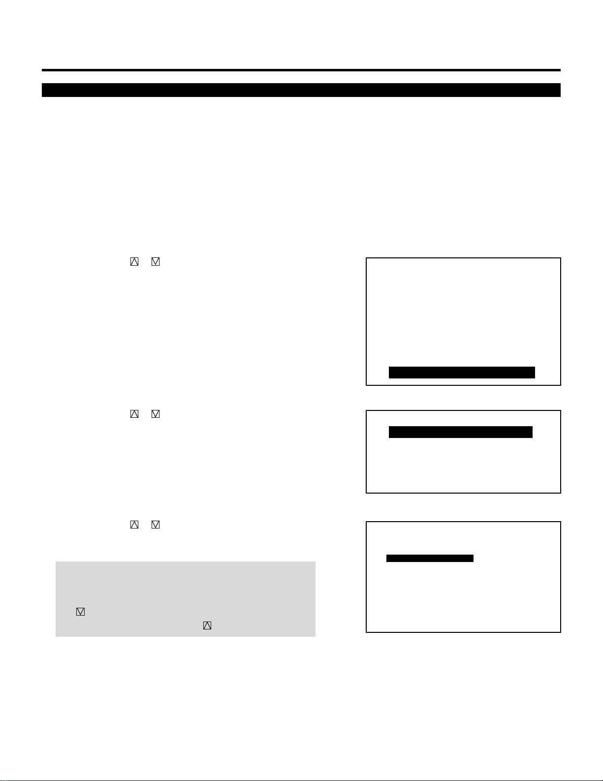
62
SETTING
ASTIG OUTPUT
This function allows you to reverse the astigmatic polarity. ASTIG
output depends on the projector installation. Select the appropriate
item according to the installation condition. Changing the ASTIG
OUTPUT setting automatically degausses the CRTs.
Proceed as follows:
1 Press the ADJUST button to display the “ADJUST” menu.
• The projector may ask you to enter your passcode.
See page 52 for the explanation of the PASSCODE.
2 Use the CURSOR or button to highlight the “9/OPTION”
line. Press ENTER to display the “OPTION” menu. You can also
select the “OPTION” menu directly by pressing the INPUT “9”
button.
• The eighth item is “8/OPTION” in stand alone adjust menu.
3 Use the CURSOR or button to highlight the “1/SETTING
MODE” line. Press ENTER to display the “SETTING MODE”
menu. You can also select the “SETTING MODE” menu directly
by pressing the INPUT “1” button.
4 Use the CURSOR or button to select the “ASTIG OUT-
PUT” item, then press ENTER to display the “ASTIG OUTPUT
MODE” menu.
NOTE: The SETTING MODE has three menus. The “ASTIG
OUTPUT” item is on the first menu (P01). To access P02 or
P03 from P01, press and hold down the CTL button then press
the button; to return to P01 from P02 or P03, press and hold
down the CTL button then press the button.
– ADJUST –
1 / SIGNAL ENTRY
2 / FOCUS
3 / ALIGNMENT
4 / CONVERGENCE
5 / WHITE BAL
6 / R,G,B GAIN
7 / HOUR METER
8 / PASSCODE
9 / OPTION
– OPTION –
1 / SETTING MODE
2 / MENU MODE
3 / SEQUENCER
4 / PJ ADDRESS
5 / VERSION
P01
CONNECT CONDITION
OPTION – SETTING MODE –
STANDALONE
ASTIG OUTPUT CEILING
FRONT
DEGAUSS
POINT CONVERGENCE ENABLE
S-VIDEO MODE SELECT S2
VIDEO MODE SELECT AUTO
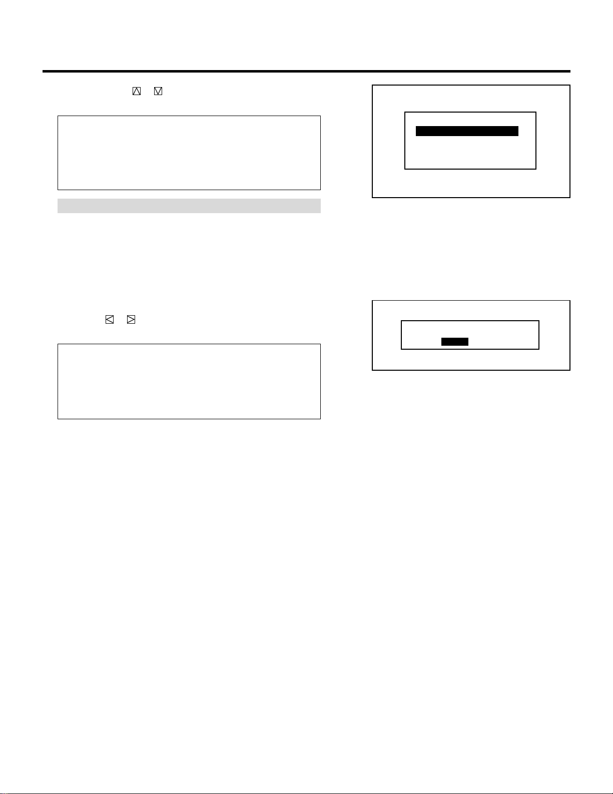
63
5 Use the CURSOR or button to select one of the four
projector installation types and press ENTER.
Items to select
• CEILING/FRONT ..Ceiling mounting type and front projection
• CEILING/REAR ....Ceiling mounting type and rear projection
• FLOOR/FRONT.....Desk top type and front projection
• FLOOR/REAR.......Desk top type and rear projection
NOTE: Pressing ENTER demagnetizes the CRTs.
6 To complete, press the END button.
• Whenever the END button is pressed, the menus will sequence
in this order:
“OPTION” menu → “ADJUST” menu → Source screen
• If the “RETURN USER MODE?” menu appears, use the
CURSOR or button to select either “YES” or “NO” and
press ENTER. This will exit the ADJUST mode.
Items to select
• YES ......... When you try to enter the ADJUST mode the next
time, you will need to re-enter your passcode.
• NO........... When you try to enter the ADJUST mode the next
time, you will not need to re-enter your passcode.
SETTING
RETURN USER MODE?
YES NO
CEILING/FRONT
CEILING/REAR
FLOOR/FRONT
FLOOR/REAR
ASTIG OUTPUT MODE
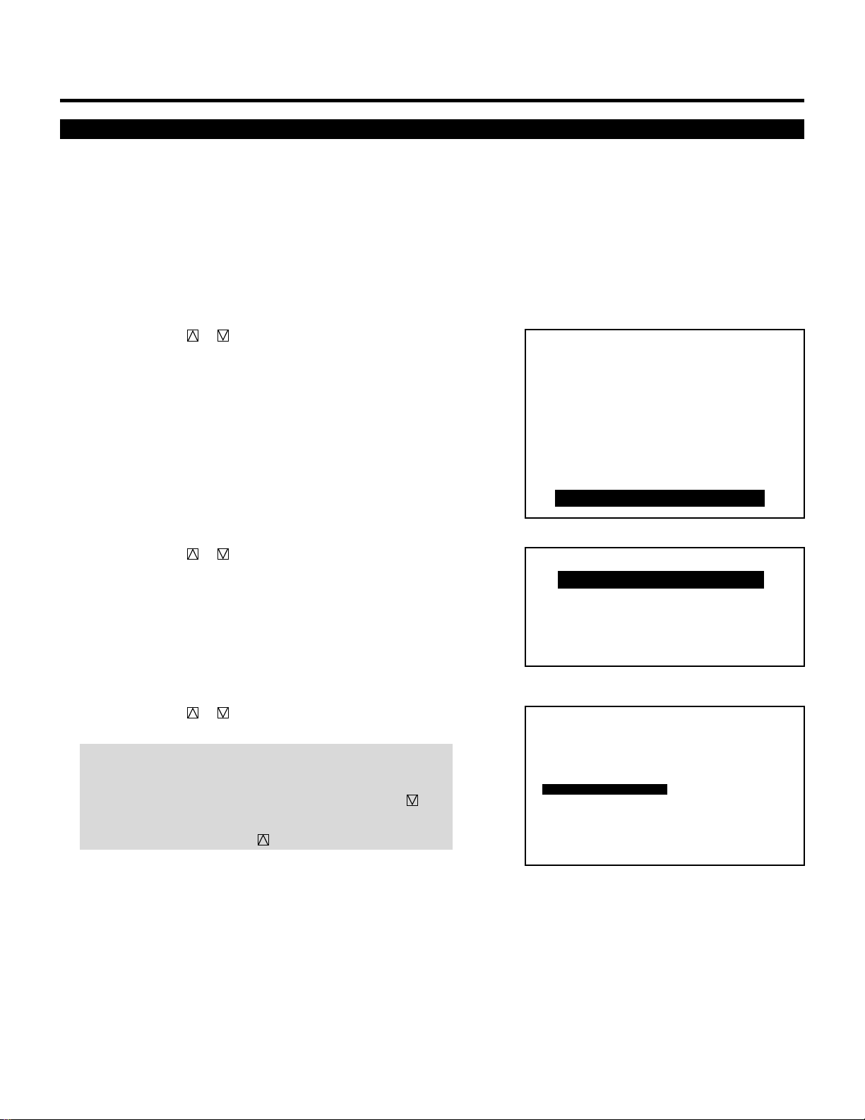
64
Degaussing
SETTING
– ADJUST –
1 / SIGNAL ENTRY
2 / FOCUS
3 / ALIGNMENT
4 / CONVERGENCE
5 / WHITE BAL
6 / R,G,B GAIN
7 / HOUR METER
8 / PASSCODE
9 / OPTION
– OPTION –
1 / SETTING MODE
2 / MENU MODE
3 / SEQUENCER
4 / PJ ADDRESS
5 / VERSION
P01
CONNECT CONDITION
OPTION – SETTING MODE –
STANDALONE
ASTIG OUTPUT CEILING
FRONT
DEGAUSS
POINT CONVERGENCE ENABLE
S-VIDEO MODE SELECT S2
VIDEO MODE SELECT AUTO
This function lets you demagnetize the CRTs. This must be done
immediately after the projector is installed.
To execute, proceed as follows:
1 Press the ADJUST button to display the “ADJUST” menu.
• The projector may ask you to enter your passcode.
See page 52 for the explanation of the PASSCODE.
2 Use the CURSOR or button to highlight the “9/OPTION”
line. Press ENTER to display the “OPTION” menu. You can also
select the “OPTION” menu directly by pressing the INPUT “9”
button.
• The eighth item is “8/OPTION” in stand alone adjust menu.
3 Use the CURSOR or button to highlight the “1/SETTING
MODE” line. Press ENTER to display the “SETTING MODE”
menu. You can also select the “SETTING MODE” menu directly
by pressing the INPUT “1” button.
4 Use the CURSOR or button to select the “DEGAUSS” item,
then press ENTER to display the “DEGAUSS START?” menu.
NOTE: The SETTING MODE has three menus. The “DEGAUSS”
item is on the first menu (P01). To access P02 or P03 from
P01, press and hold down the CTL button then press the
button; to return to P01 from P02 or P03, press and hold down
the CTL button then press the button.
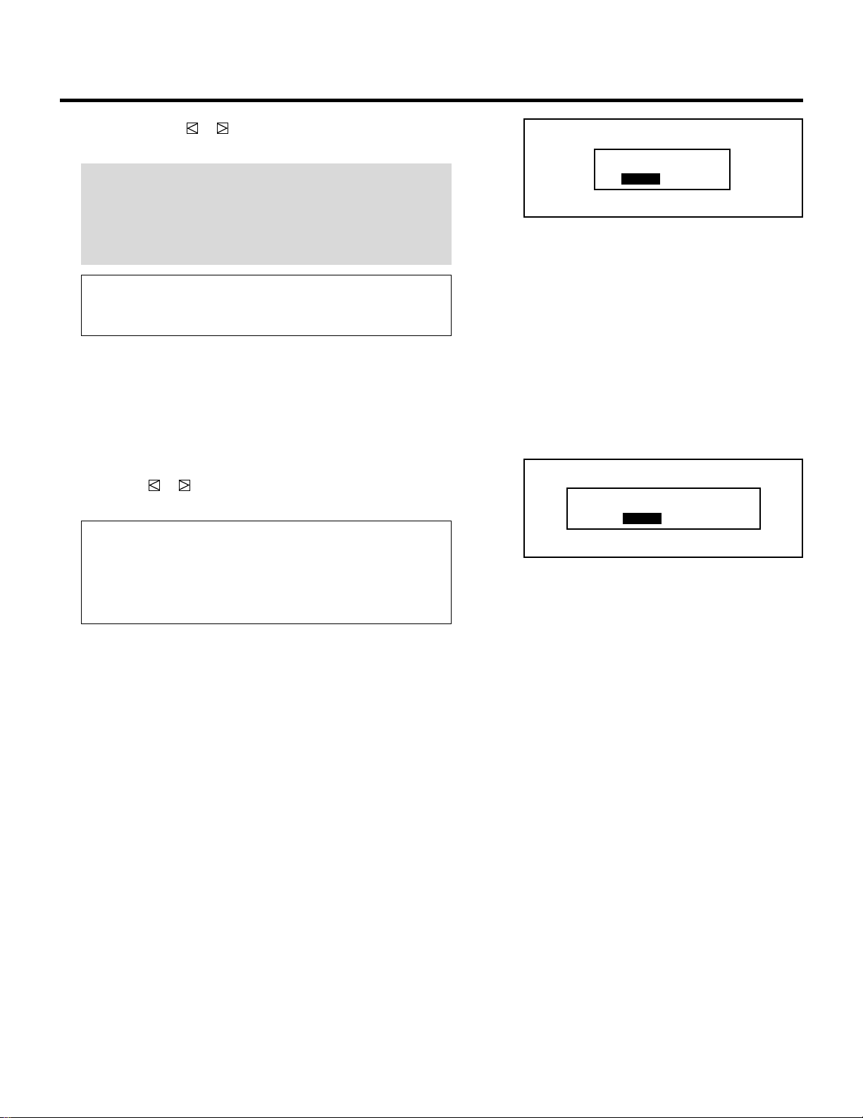
65
5 Use the CURSOR or button to select either “YES” or “NO”
and press ENTER.
IMPORTANT: Use this function only once after installing the
projector.
Also, when the projector’s configuration has changed using the
“ASTIG OUTPUT” menu, the CRTs will be demagnetized
automatically.
Items to select
• YES ......... Demagnetizes the CRTs.
• NO........... Does not demagnetizes the CRTs.
6 To complete, press the END button.
• Whenever the END button is pressed, the menus will sequence
in this order:
“OPTION” menu → “ADJUST” menu → Source screen
• If the “RETURN USER MODE?” menu appears, use the
CURSOR or button to select either “YES” or “NO” and
press ENTER. This will exit the ADJUST mode.
Items to select
• YES ......... When you try to enter the ADJUST mode the next
time, you will need to re-enter your passcode.
• NO........... When you try to enter the ADJUST mode the next
time, you will not need to re-enter your passcode.
SETTING
RETURN USER MODE?
YES NO
DEGAUSS START?
YES NO
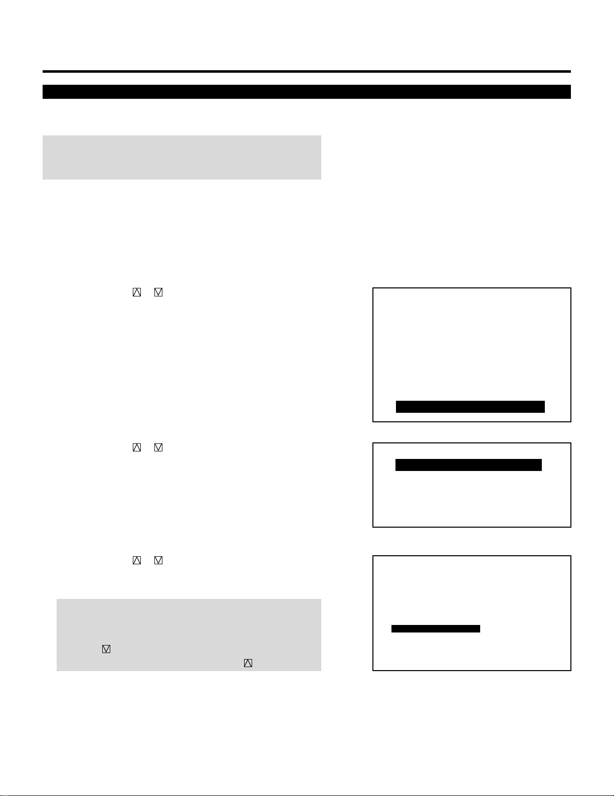
66
SETTING
Point Convergence
– ADJUST –
1 / SIGNAL ENTRY
2 / FOCUS
3 / ALIGNMENT
4 / CONVERGENCE
5 / WHITE BAL
6 / R,G,B GAIN
7 / HOUR METER
8 / PASSCODE
9 / OPTION
– OPTION –
1 / SETTING MODE
2 / MENU MODE
3 / SEQUENCER
4 / PJ ADDRESS
5 / VERSION
P01
CONNECT CONDITION
OPTION – SETTING MODE –
STANDALONE
ASTIG OUTPUT CEILING
FRONT
DEGAUSS
ENABLE
S-VIDEO MODE SELECT S2
POINT CONVERGENCE
VIDEO MODE SELECT AUTO
Activate the point convergence function after installing the point
convergence board.
NOTE: You need to install the optional Point Convergence board for
the 6PG XTRA. This function should always be enabled for the 9PG
XTRA.
To activate the point convergence, proceed as follows:
1 Press the ADJUST button to display the “ADJUST” menu.
• The projector may ask you to enter your passcode.
See page 52 for the explanation of the PASSCODE.
2 Use the CURSOR or button to highlight the “9/OPTION”
line. Press ENTER to display the “OPTION” menu. You can also
select the “OPTION” menu directly by pressing the INPUT “9”
button.
• The eighth item is “8/OPTION” in stand alone adjust menu.
3 Use the CURSOR or button to highlight the “1/SETTING
MODE” line. Press ENTER to display the “SETTING MODE”
menu. You can also select the “SETTING MODE” menu directly
by pressing the INPUT “1” button.
4 Use the CURSOR or button to select the “POINT CON-
VERGENCE” item, then press ENTER to display the “POINT
CONVERGENCE” menu.
NOTE: The SETTING MODE has three menus. The “POINT
CONVERGENCE” menu is on the first menu (P01). To access
P02 or P03 from P01, press and hold down the CTL button then
press the button; to return to P01 from P02 or P03, press
and hold down the CTL button then press the button.

67
SETTING
5 Use the CURSOR or button to select either “ENABLE” or
“DISABLE” and then press ENTER.
Items to select
• ENABLE ... The point convergence will be activated.
• DISABLE.. The point convergence will be deactivated.
6 To end, press the END button.
• Whenever the END button is pressed, the menus will sequence
in this order:
“OPTION” menu → “ADJUST” menu → Source screen
• If the “RETURN USER MODE?” menu appears, use the
CURSOR or button to select either “YES” or “NO” and
press ENTER. This will exit the ADJUST mode.
Items to select
• YES ......... When you try to enter the ADJUST mode the next
time, you will need to re-enter your passcode.
• NO........... When you try to enter the ADJUST mode the next
time, you will not need to re-enter your passcode.
RETURN USER MODE?
YES NO
ENABLE
DISABLE
POINT CONVERGENCE
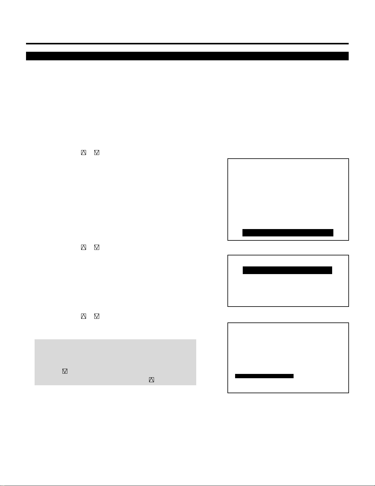
68
SETTING
S-Video Mode Selection
– ADJUST –
1 / SIGNAL ENTRY
2 / FOCUS
3 / ALIGNMENT
4 / CONVERGENCE
5 / WHITE BAL
6 / R,G,B GAIN
7 / HOUR METER
8 / PASSCODE
9 / OPTION
– OPTION –
1 / SETTING MODE
2 / MENU MODE
3 / SEQUENCER
4 / PJ ADDRESS
5 / VERSION
P01
CONNECT CONDITION
OPTION – SETTING MODE –
STANDALONE
ASTIG OUTPUT CEILING
FRONT
DEGAUSS
ENABLE
S2
POINT CONVERGENCE
S-VIDEO MODE SELECT
AUTOVIDEO MODE SELECT
This function is used to select the S-video signal detection mode.
This allows identifying of the S-video signals with different aspect
ratio: squeeze or full mode(16 : 9) and letter box (4 : 3) signals.
To set, proceed as follows:
1 Press the ADJUST button to display the “ADJUST” menu.
• The projector may ask you to enter your passcode.
See page 52 for the explanation of the PASSCODE.
2 Use the CURSOR or button to highlight the “9/OPTION”
line. Press ENTER to display the “OPTION” menu. You can also
select the “OPTION” menu directly by pressing the INPUT “9”
button.
• The eighth item is “8/OPTION” in stand alone adjust menu.
3 Use the CURSOR or button to highlight the “1/SETTING
MODE” line. Press ENTER to display the “SETTING MODE”
menu. You can also select the “SETTING MODE” menu directly
by pressing the INPUT “1” button.
4 Use the CURSOR or button to select the “S-VIDEO MODE
SELECT” item, then press ENTER to display the “S-VIDEO
MODE SELECT” menu.
NOTE: The SETTING MODE has three menus. The “S-VIDEO
MODE SELECT” menu is on the first menu (P01). To access
P02 or P03 from P01, press and hold down the CTL button then
press the button; to return to P01 from P02 or P03, press
and hold down the CTL button then press the button.
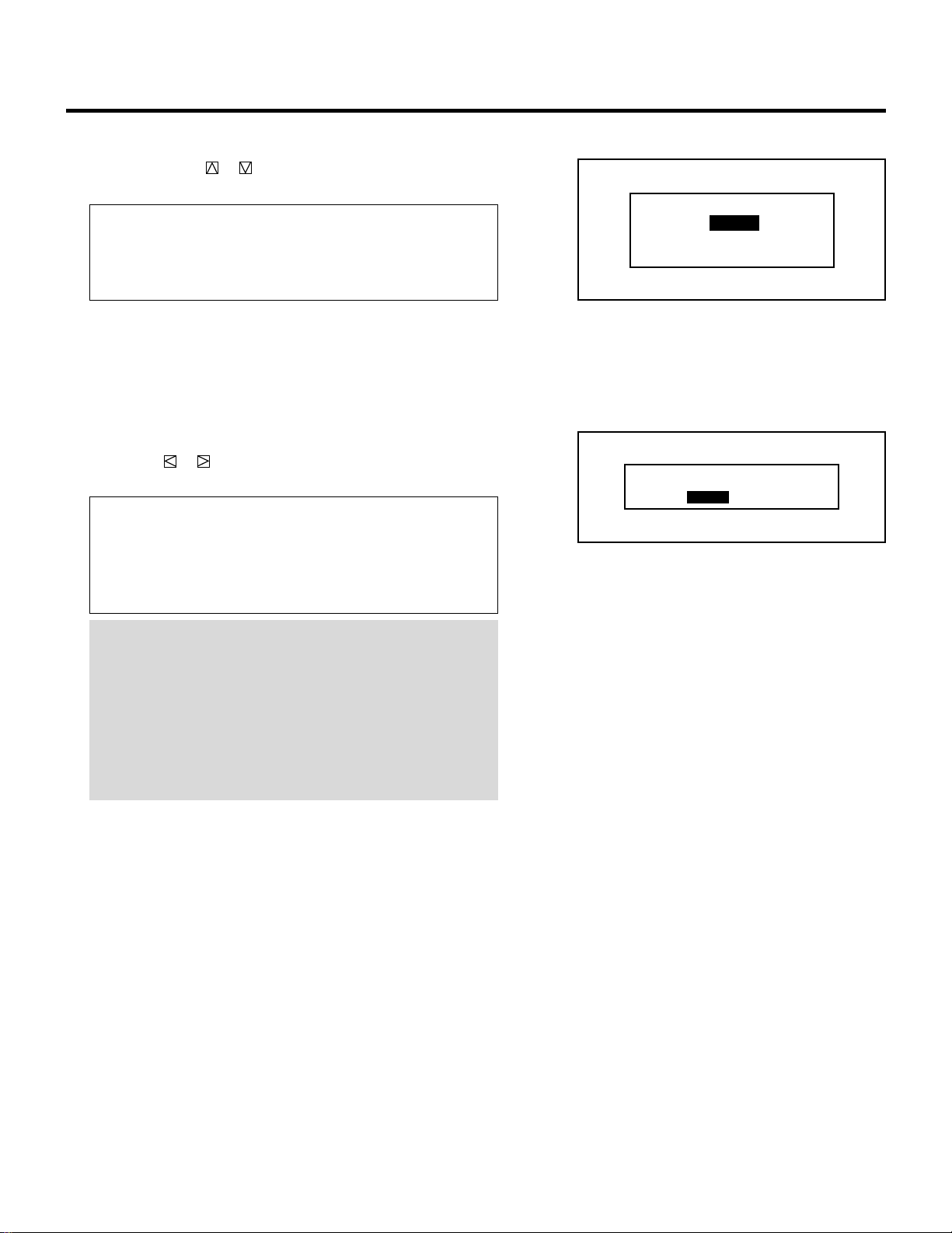
69
SETTING
5 Use the CURSOR or button to select one of the three items:
S2, S1, and OFF, and then press ENTER.
Items to select
S2.............. Identifies squeeze and letter box signals.
S1.............. Identifies a squeeze signal only.
OFF ............ Does not identify any S-video signal.
6 To end, press the END button.
• Whenever the END button is pressed, the menus will sequence
in this order:
“OPTION” menu → “ADJUST” menu → Source screen
• If the “RETURN USER MODE?” menu appears, use the
CURSOR or button to select either “YES” or “NO” and
press ENTER. This will exit the ADJUST mode.
Items to select
• YES ......... When you try to enter the ADJUST mode the next
time, you will need to re-enter your passcode.
• NO........... When you try to enter the ADJUST mode the next
time, you will not need to re-enter your passcode.
NOTE :
• The input signal must be compatible with the S2/S1 MODE
standard.
Refer to the user manual included with the connected equip-
ment for more information.
• The identification function may not work correctly with a non-
compatible signal. If this happens, select “OFF” from the “S-
VIDEO MODE SELECT” menu.
RETURN USER MODE?
YES NO
S2
S1
OFF
S-VIDEO MODE SELECT
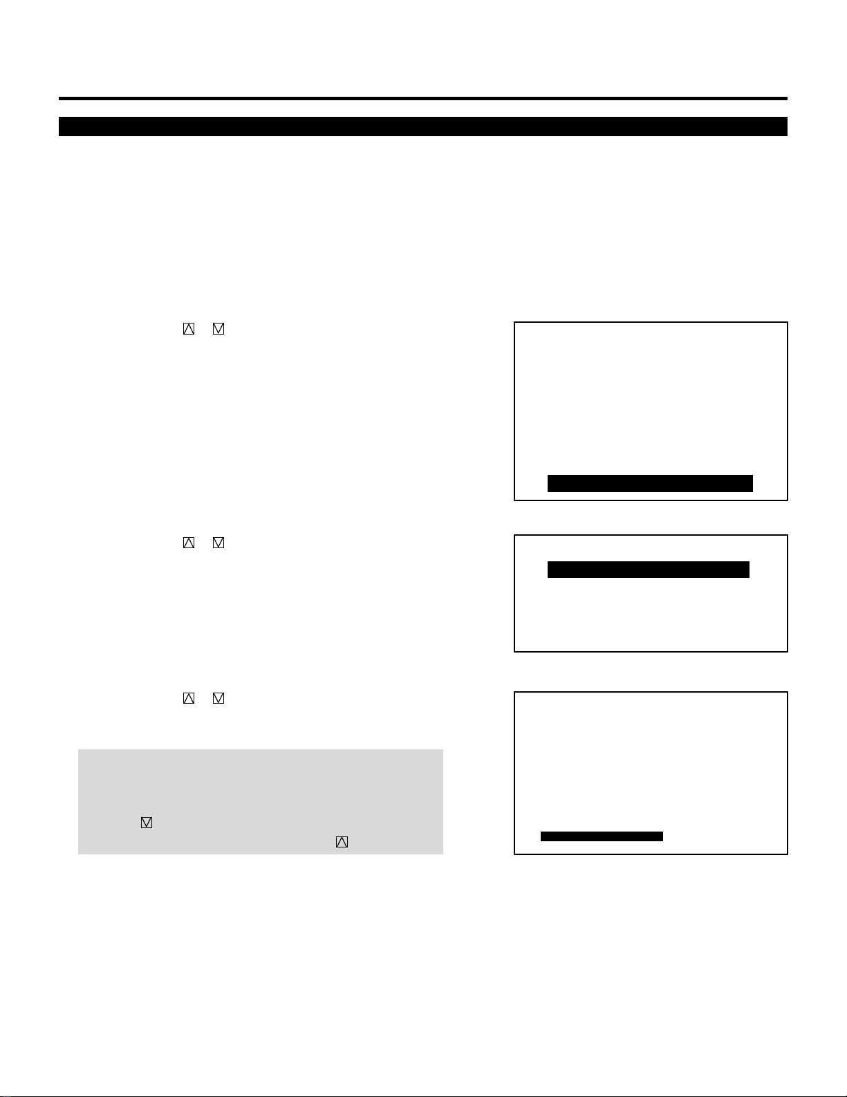
70
Video Mode Selection
SETTING
– ADJUST –
1 / SIGNAL ENTRY
2 / FOCUS
3 / ALIGNMENT
4 / CONVERGENCE
5 / WHITE BAL
6 / R,G,B GAIN
7 / HOUR METER
8 / PASSCODE
9 / OPTION
– OPTION –
1 / SETTING MODE
2 / MENU MODE
3 / SEQUENCER
4 / PJ ADDRESS
5 / VERSION
P01
CONNECT CONDITION
OPTION – SETTING MODE –
STANDALONE
ASTIG OUTPUT CEILING
FRONT
DEGAUSS
ENABLE
S2
POINT CONVERGENCE
S-VIDEO MODE SELECT
AUTOVIDEO MODE SELECT
This function is used to select the NTSC 3.58, NTSC 4.43, PAL or
SECAM video standard.
To select any one of the video standards, proceed as follows:
1 Press the ADJUST button to display the “ADJUST” menu.
• The projector may ask you to enter your passcode.
See page 52 for the explanation of the PASSCODE.
2 Use the CURSOR or button to highlight the “9/OPTION”
line. Press ENTER to display the “OPTION” menu. You can also
select the “OPTION” menu directly by pressing the INPUT “9”
button.
• The eighth item is “8/OPTION” in stand alone adjust menu.
3 Use the CURSOR or button to highlight the “1/SETTING
MODE” line. Press ENTER to display the “SETTING MODE”
menu. You can also select the “SETTING MODE” menu directly
by pressing the INPUT “1” button.
4 Use the CURSOR or button to select the “VIDEO MODE
SELECT” item, then press ENTER to display the “VIDEO
MODE SELECT” menu.
NOTE: The SETTING MODE has three menus. The “VIDEO
MODE SELECT” menu is on the first menu (P01). To access
P02 or P03 from P01, press and hold down the CTL button then
press the button; to return to P01 from P02 or P03, press
and hold down the CTL button then press the button.
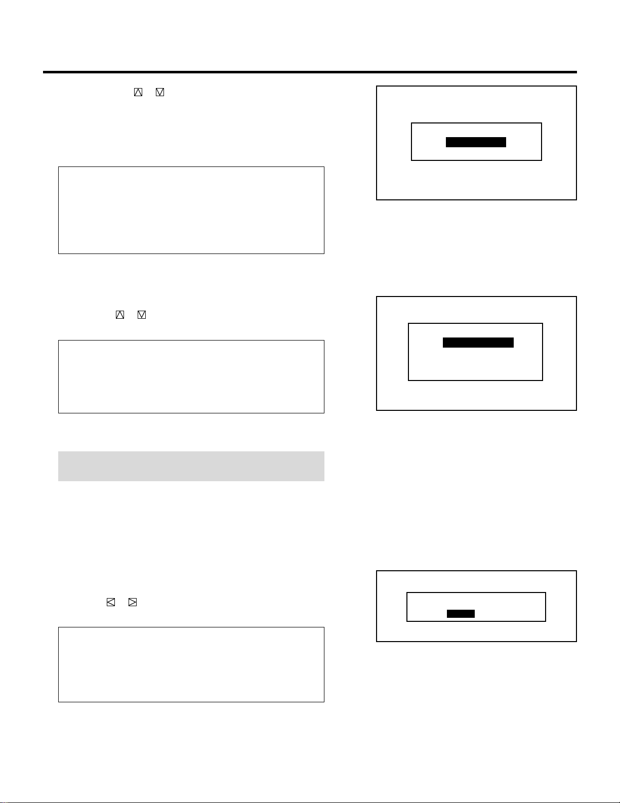
71
5 Use the CURSOR or button to select either “AUTO” or
“MANUAL” and then press ENTER.
When selecting “AUTO”
One of the video standards is selected automatically and is
displayed in the SOURCE INFORMATION screen.
Video Modes
• NTSC3.58............Indicates the NTSC3.58 video standard
• NTSC4.43............Indicates the NTSC4.43 video standard
• PAL .....................Indicates the PAL video standard
• SECAM ................Indicates the SECAM video standard
• RGB.....................Indicates the RGB mode
• Select “AUTO” in normal operation.
When selecting “MANUAL”
The “MANUAL MODE SELECT” menu will be displayed. Use
the CURSOR or button to select the preferred video mode
and then press ENTER.
Items to select
• NTSC3.58 Switches to the NTSC3.58 mode
• NTSC4.43 Switches to the NTSC4.43 mode
• PAL ......... Switches to the PAL mode
• SECAM .... Switches to the SECAM mode
• Select “MANUAL” when connecting to poor quality signal or
non-standard signals such as video games.
NOTE: The projector may not function correctly with a mono-
chrome signals in the AUTO mode.
6 To complete, press the END button.
• Whenever the END button is pressed, the menus will sequence
in this order:
“OPTION” menu → “ADJUST” menu → Source screen
• When your passcode is in effect, the “RETURN USER
MODE?” menu is displayed. If this happens, use the
CURSOR or button to select either “YES” or “NO” and
press ENTER.
Items to select
• YES ......... When you try to enter the ADJUST mode the next
time, you will need to re-enter your passcode.
• NO........... When you try to enter the ADJUST mode the next
time, you will not need to re-enter your passcode.
SETTING
RETURN USER MODE?
YES NO
AUTO
MANUAL
VIDEO MODE SELECT
NTSC 3.58
NTSC 4.43
PAL
SECAM
MANUAL MODE SELECT
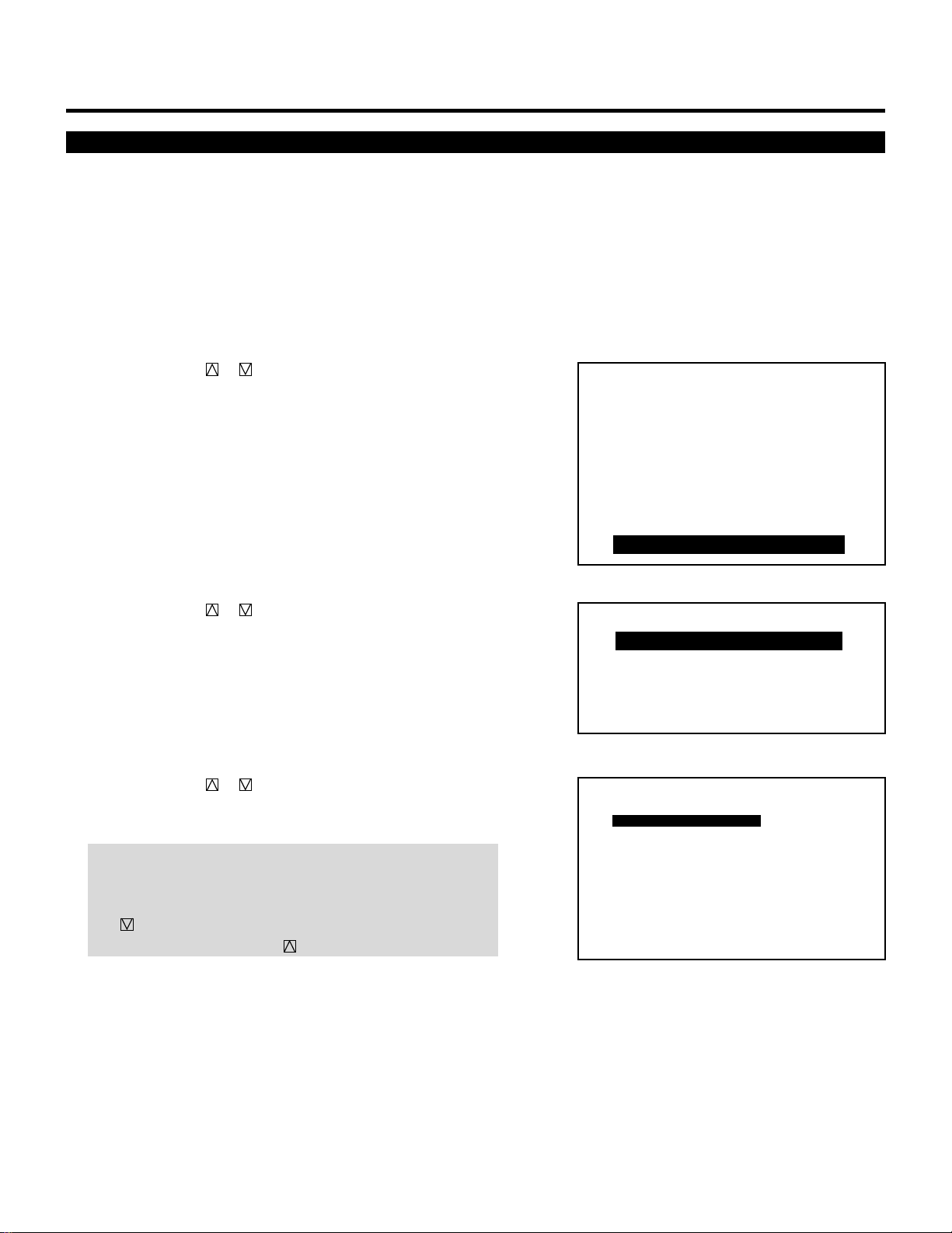
72
SETTING
Default Input Selection
You can set the projector to default to any one of its inputs each time
the projector is turned on.
Proceed as follows:
1 Press the ADJUST button to display the “ADJUST” menu.
• The projector may ask you to enter your passcode.
See page 52 for the explanation of the PASSCODE.
2 Use the CURSOR or button to highlight the “9/OPTION”
line. Press ENTER to display the “OPTION” menu. You can also
select the “OPTION” menu directly by pressing the INPUT “9”
button.
• The eighth item is “8/OPTION” in stand alone adjust menu.
3 Use the CURSOR or button to highlight the “1/SETTING
MODE” line. Press ENTER to display the “SETTING MODE”
menu. You can also select the “SETTING MODE” menu directly
by pressing the INPUT “1” button.
4 Use the CURSOR or button to select the “DEFAULT
INPUT SELECT” item on Page 2, then press ENTER to display
the “DEFAULT INPUT SELECT” menu.
NOTE: The SETTING MODE has three menus. The “DEFAULT
INPUT SELECT” item is on the second menu (P02). To access
P02 from P01, press and hold down the CTL button then press
the button; to return to P01 from P02, press and hold down
the CTL button then press the button.
– ADJUST –
1 / SIGNAL ENTRY
2 / FOCUS
3 / ALIGNMENT
4 / CONVERGENCE
5 / WHITE BAL
6 / R,G,B GAIN
7 / HOUR METER
8 / PASSCODE
9 / OPTION
– OPTION –
1 / SETTING MODE
2 / MENU MODE
3 / SEQUENCER
4 / PJ ADDRESS
5 / VERSION
P02 OPTION – SETTING MODE –
LAST
AUTO POWER ON MODE INACTIVE
WARM-UP MODE
OFF
SOUND
PHOSPHOR SAVER
SIGNAL SWITCHING
INACTIVE
MUTE ON
PICTURE
MUTE ON
DEFAULT INPUT SELECT
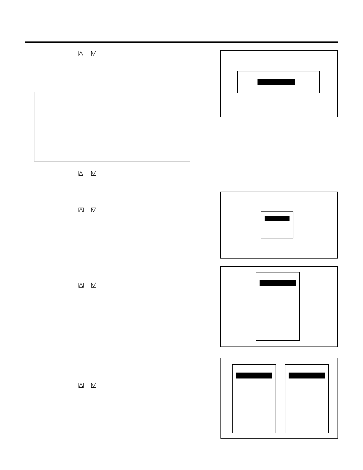
73
SETTING
RGB
VIDEO
S-VIDEO
5 Use the CURSOR or button to select either “LAST” or
“DEFAULT” and press ENTER.
• Selecting “LAST” completes setting. Go on to step 7.
• Selecting “DEFAULT” displays the “Default input” screen. Go
on to step 6.
Items to select
• LAST ....... Sets the projector to default to the previous last
active input each time the projector is turned on.
Note: An input must be active for a minimum of 10
minutes before it is recognized as the last active
signal.
• DEFAULT. Displays the same source input every time the
projector is started up.
6 Use the CURSOR or button to select an input and then press
the ENTER button.
When used in stand alone operation:
The default input screen will be displayed.
Use the CURSOR or button to select “VIDEO”, “RGB”, or
“S-VIDEO” and press ENTER.
When used with a single Switcher:
The “MASTER” slot menu will be displayed.
Use the CURSOR or button to select the desired slot
number “1” through “10(0)” and then press ENTER.
When used with two or more Switchers:
The “MASTER” and “SLAVE” slot number menu will be
displayed.
Use the CURSOR or button to select the master slot number
first and then select the slave slot number “1” through “10(0)”.
Press ENTER.
LAST
DEFAULT
DEFAULT INPUT SELECT
SLOT–01
SLOT–02
SLOT–03
SLOT–04
SLOT–05
SLOT–06
SLOT–07
SLOT–08
SLOT–09
SLOT–10
MASTER
SLOT–01
SLOT–02
SLOT–03
SLOT–04
SLOT–05
SLOT–06
SLOT–07
SLOT–08
SLOT–09
SLOT–10
MASTER
SLOT–01
SLOT–02
SLOT–03
SLOT–04
SLOT–05
SLOT–06
SLOT–07
SLOT–08
SLOT–09
SLOT–10
SLAVE
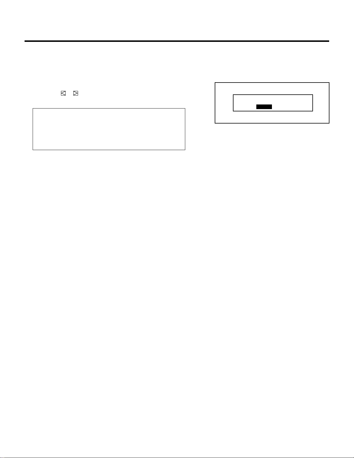
74
7 To complete, press the END button.
• Whenever the END button is pressed, the menus will sequence
in this order:
“OPTION” menu → “ADJUST” menu → Source screen
• If the “RETURN USER MODE?” menu appears, use the
CURSOR or button to select either “YES” or “NO” and
press ENTER. This will exit the ADJUST mode.
Items to select
• YES ......... When you try to enter the ADJUST mode the next
time, you will need to re-enter your passcode.
• NO........... When you try to enter the ADJUST mode the next
time, you will not need to re-enter your passcode.
SETTING
RETURN USER MODE?
YES NO
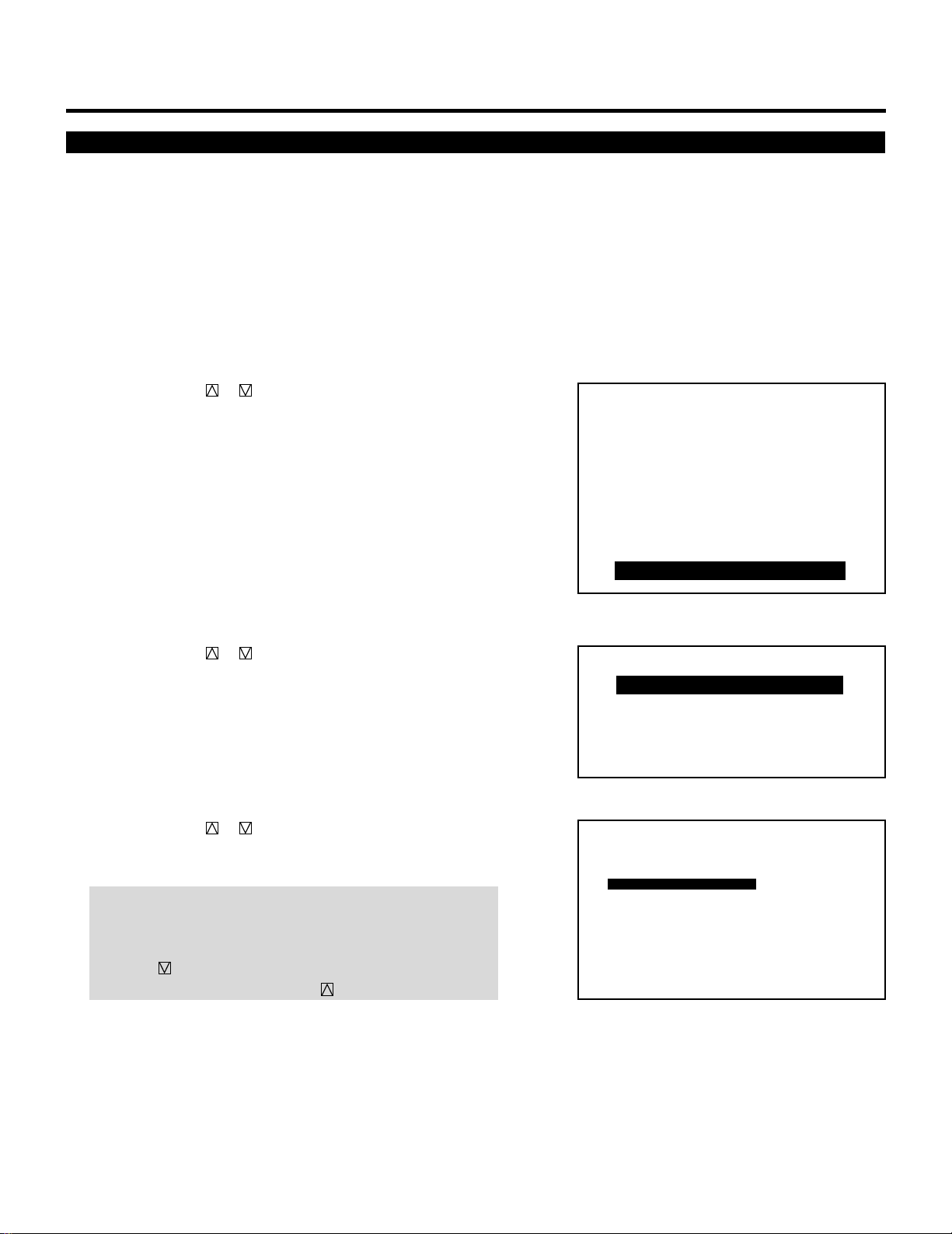
75
SETTING
Auto Power ON Mode Setting
The AUTO POWER ON MODE is a convenient way to start up the
projector without pressing the POWER button. You can turn the
projector on and off by supplying AC power to the projector.
To do this, proceed as follows:
1 Press the ADJUST button to display the “ADJUST” menu.
• The projector may ask you to enter your passcode.
See page 52 for the explanation of the PASSCODE.
2 Use the CURSOR or button to highlight the “9/OPTION”
line. Press ENTER to display the “OPTION” menu. You can also
select the “OPTION” menu directly by pressing the INPUT “9”
button.
• The eighth item is “8/OPTION” in stand alone adjust menu.
3 Use the CURSOR or button to highlight the “1/SETTING
MODE” line. Press ENTER to display the “SETTING MODE”
menu. You can also select the “SETTING MODE” menu directly
by pressing the INPUT “1” button.
4 Use the CURSOR or button to select the “AUTO POWER
ON MODE” item on Page 2, then press ENTER to display the
“AUTO POWER ON MODE” menu.
NOTE: The SETTING MODE has three menus. The “AUTO
POWER ON MODE” item is on the second menu (P02). To
access P02 from P01, press and hold down the CTL button then
press the button; to return to P01 from P02, press and hold
down the CTL button then press the button.
– ADJUST –
1 / SIGNAL ENTRY
2 / FOCUS
3 / ALIGNMENT
4 / CONVERGENCE
5 / WHITE BAL
6 / R,G,B GAIN
7 / HOUR METER
8 / PASSCODE
9 / OPTION
– OPTION –
1 / SETTING MODE
2 / MENU MODE
3 / SEQUENCER
4 / PJ ADDRESS
5 / VERSION
P02 OPTION – SETTING MODE –
LAST
AUTO POWER ON MODE INACTIVE
WARM-UP MODE
OFF
SOUND
PHOSPHOR SAVER
SIGNAL SWITCHING
INACTIVE
MUTE ON
PICTURE
MUTE ON
DEFAULT INPUT SELECT
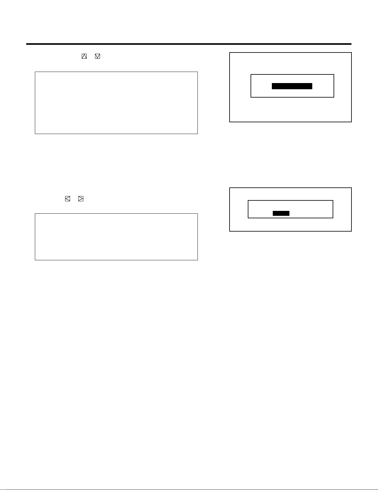
76
5 Use the CURSOR or button to select either “ACTIVE” or
“INACTIVE” and press the ENTER button.
Items to select
• INACTIVE. Normal operation setting. Power ON is accom-
plished through the rear panel or the POWER
button on the remote control.
• ACTIVE .... Bypasses rear panel power button (or the POWER
button on the remote control) to allow power ON
to be controlled by an AC switched outlet.
6 To complete, press the END button.
• Whenever the END button is pressed, the menus will sequence
in this order:
“OPTION” menu → “ADJUST” menu → Source screen
• If the “RETURN USER MODE?” menu appears, use the
CURSOR or button to select either “YES” or “NO” and
then press ENTER.
Items to select
• YES ......... When you try to enter the ADJUST mode the next
time, you will need to re-enter your passcode.
• NO........... When you try to enter the ADJUST mode the next
time, you will not need to re-enter your passcode.
SETTING
RETURN USER MODE?
YES NO
INACTIVE
ACTIVE
AUTO POWER ON MODE
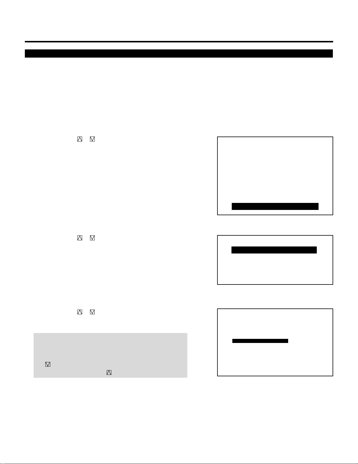
77
SETTING
Warm-up Mode Setting
This function allows you to automatically warm up the projector for
about 15 minutes when the projector is turned on.
To set the Warm-up mode, proceed as follows:
1 Press the ADJUST button to display the “ADJUST” menu.
• The projector may ask you to enter your passcode.
See page 52 for the explanation of the PASSCODE.
2 Use the CURSOR or button to highlight the “9/OPTION”
line. Press ENTER to display the “OPTION” menu. You can also
select the “OPTION” menu directly by pressing the INPUT “9”
button.
• The eighth item is “8/OPTION” in stand alone adjust menu.
3 Use the CURSOR or button to highlight the “1/SETTING
MODE” line. Press ENTER to display the “SETTING MODE”
menu. You can also select the “SETTING MODE” menu directly
by pressing the INPUT “1” button.
4 Use the CURSOR or button to select the “WARM-UP
MODE” item on Page 2, then press ENTER to display the
“WARM-UP MODE” menu.
NOTE: The SETTING MODE has three menus. The “WARM-UP
MODE” item is on the second menu (P02). To access P02 from
P01, press and hold down the CTL button then press
the button; to return to P01 from P02, press and hold down
the CTL button then press the button.
– ADJUST –
1 / SIGNAL ENTRY
2 / FOCUS
3 / ALIGNMENT
4 / CONVERGENCE
5 / WHITE BAL
6 / R,G,B GAIN
7 / HOUR METER
8 / PASSCODE
9 / OPTION
– OPTION –
1 / SETTING MODE
2 / MENU MODE
3 / SEQUENCER
4 / PJ ADDRESS
5 / VERSION
P02 OPTION – SETTING MODE –
LAST
AUTO POWER ON MODE INACTIVE
OFF
SOUND
PHOSPHOR SAVER
SIGNAL SWITCHING
INACTIVE
MUTE ON
PICTURE
MUTE ON
DEFAULT INPUT SELECT
WARM-UP MODE
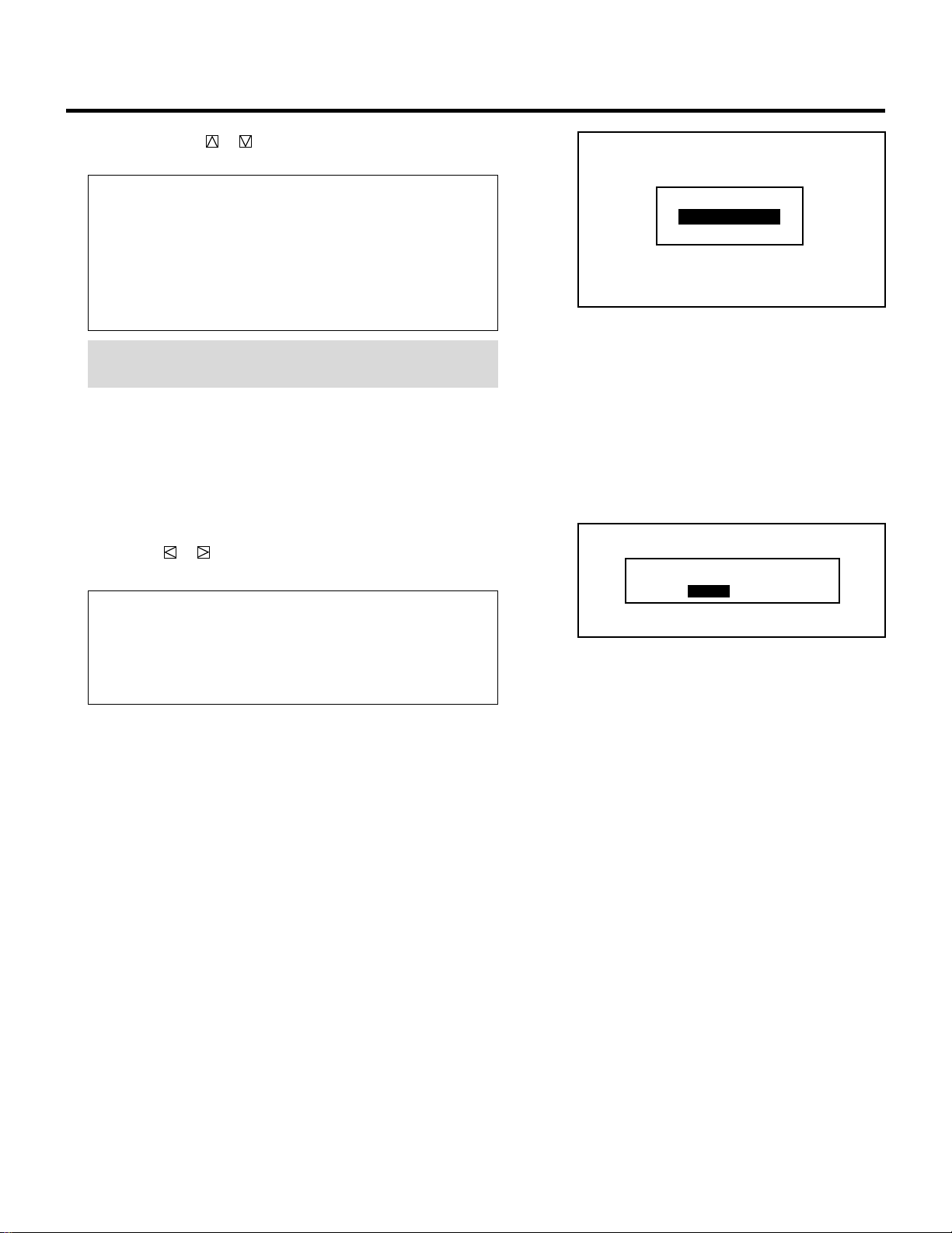
78
5 Use the CURSOR or button to select either “ACTIVE” or
“INACTIVE” and press ENTER.
Items to select
• INACTIVE. Displays the input source after the projector is
turned on.
• ACTIVE .... Activates the warm-up program after the projector
is turned on. The ALL WHITE test pattern will be
displayed. The projector starts counting down
from 15 minutes to 0.
NOTE: To interrupt and cancel the warm-up cycle, press the
END button.
6 To complete, press the END button.
• Whenever the END button is pressed, the menus will sequence
in this order:
“OPTION” menu → “ADJUST” menu → Source screen
• If the “RETURN USER MODE?” menu appears, use the
CURSOR or button to select either “YES” or “NO” and
then press ENTER.
Items to select
• YES ......... When you try to enter the ADJUST mode the next
time, you will need to re-enter your passcode.
• NO........... When you try to enter the ADJUST mode the next
time, you will not need to re-enter your passcode.
SETTING
RETURN USER MODE?
YES NO
INACTIVE
ACTIVE
WARM-UP MODE
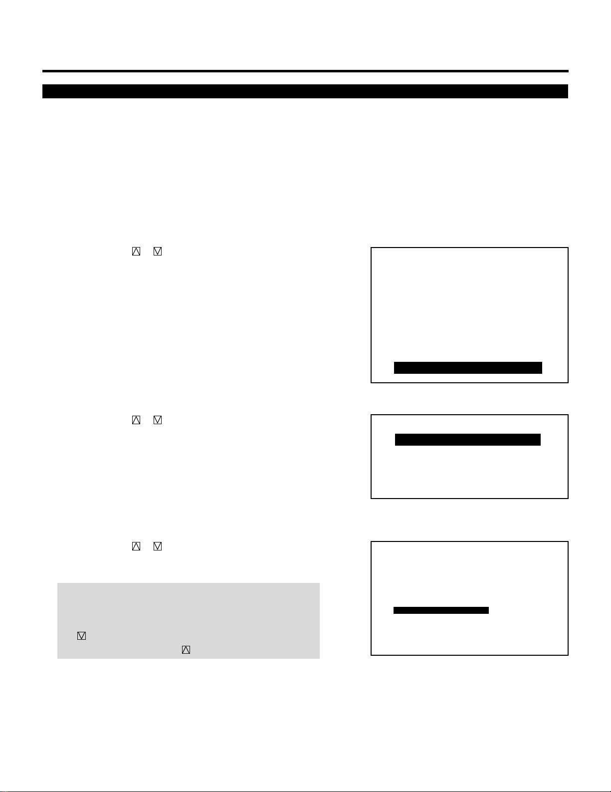
79
SETTING
Phosphor Saver Setting
This function allows you to safeguard the CRTs against burns by
shifting the image vertically and horizontally on the screen in the
regular intervals. This can prolong the life of CRT of the projector.
To set the Phosphor saver, proceed as follows:
1 Press the ADJUST button to display the “ADJUST” menu.
• The projector may ask you to enter your passcode.
See page 52 for the explanation of the PASSCODE.
2 Use the CURSOR or button to highlight the “9/OPTION”
line. Press ENTER to display the “OPTION” menu. You can also
select the “OPTION” menu directly by pressing the INPUT “9”
button.
• The eighth item is “8/OPTION” in stand alone adjust menu.
3 Use the CURSOR or button to highlight the “1/SETTING
MODE” line. Press ENTER to display the “SETTING MODE”
menu. You can also select the “SETTING MODE” menu directly
by pressing the INPUT “1” button.
4 Use the CURSOR or button to select the “PHOSPHOR
SAVER” item on Page 2, then press ENTER to display the
“PHOSPHOR SAVER” menu.
NOTE: The SETTING MODE has three menus. The “PHOSPHOR
SAVER” item is on the second menu (P02). To access P02 from
P01, press and hold down the CTL button then press
the button; to return to P01 from P02, press and hold down
the CTL button then press the button.
– ADJUST –
1 / SIGNAL ENTRY
2 / FOCUS
3 / ALIGNMENT
4 / CONVERGENCE
5 / WHITE BAL
6 / R,G,B GAIN
7 / HOUR METER
8 / PASSCODE
9 / OPTION
– OPTION –
1 / SETTING MODE
2 / MENU MODE
3 / SEQUENCER
4 / PJ ADDRESS
5 / VERSION
P02 OPTION – SETTING MODE –
LAST
AUTO POWER ON MODE INACTIVE
OFF
SOUND
PHOSPHOR SAVER
SIGNAL SWITCHING
INACTIVE
MUTE ON
PICTURE
MUTE ON
DEFAULT INPUT SELECT
WARM-UP MODE
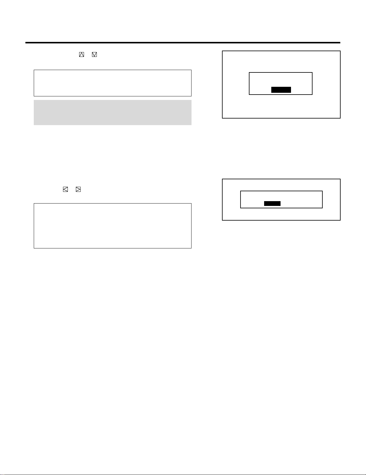
80
5 Use the CURSOR or button to select either “OFF” or “ON”
and press ENTER.
Items to select
• OFF.......... Deactivates the PHOSPHOR SAVER function.
• ON........... Activates the PHOSPHOR SAVER function.
NOTE: When the on-screen display appears or you are in the
adjustment mode, this function is cancelled. This can cause the
source screen to be shifted.
6 To complete, press the END button.
• Whenever the END button is pressed, the menus will sequence
in this order:
“OPTION” menu → “ADJUST” menu → Source screen
• If the “RETURN USER MODE?” menu appears, use the
CURSOR or button to select either “YES” or “NO” and
then press ENTER.
Items to select
• YES ......... When you try to enter the ADJUST mode the next
time, you will need to re-enter your passcode.
• NO........... When you try to enter the ADJUST mode the next
time, you will not need to re-enter your passcode.
SETTING
RETURN USER MODE?
YES NO
OFF
ON
PHOSPHOR SAVER
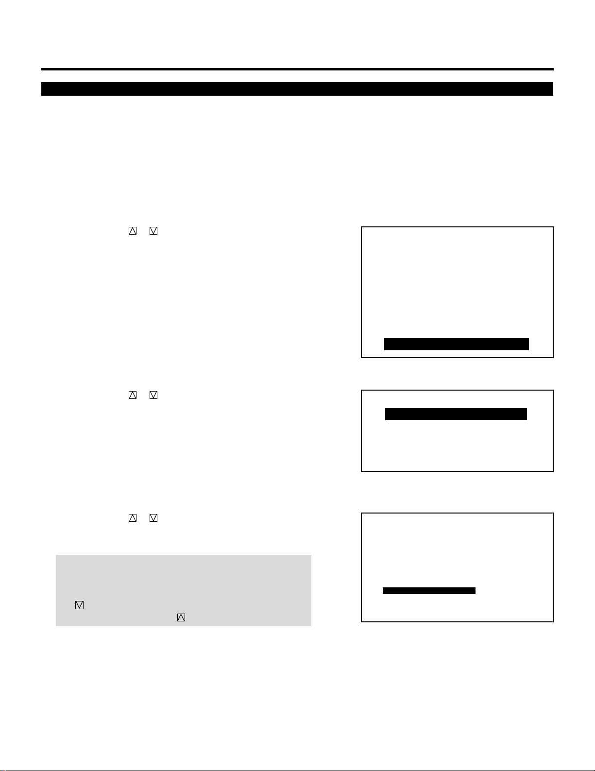
81
SETTING
Signal Switching Mute Mode Setting
This function allows you to mute the picture and/or sound during
signal switching.
To set the Signal Switching Mute mode, proceed as follows:
1 Press the ADJUST button to display the “ADJUST” menu.
• The projector may ask you to enter your passcode.
See page 52 for the explanation of the PASSCODE.
2 Use the CURSOR or button to highlight the “9/OPTION”
line. Press ENTER to display the “OPTION” menu. You can also
select the “OPTION” menu directly by pressing the INPUT “9”
button.
• The eighth item is “8/OPTION” in stand alone adjust menu.
3 Use the CURSOR or button to highlight the “1/SETTING
MODE” line. Press ENTER to display the “SETTING MODE”
menu. You can also select the “SETTING MODE” menu directly
by pressing the INPUT “1” button.
4 Use the CURSOR or button to select the “SIGNAL
SWITCHING” item on Page 2, then press ENTER to display the
“SIGNAL SWITCHING” menu.
NOTE: The SETTING MODE has three menus. The “SIGNAL
SWITCHING” menu is on the second menu (P02). To access
P02 from P01, press and hold down the CTL button then press
the button; to return to P01 from P02, press and hold down
the CTL button then press the button.
– ADJUST –
1 / SIGNAL ENTRY
2 / FOCUS
3 / ALIGNMENT
4 / CONVERGENCE
5 / WHITE BAL
6 / R,G,B GAIN
7 / HOUR METER
8 / PASSCODE
9 / OPTION
– OPTION –
1 / SETTING MODE
2 / MENU MODE
3 / SEQUENCER
4 / PJ ADDRESS
5 / VERSION
P02 OPTION – SETTING MODE –
LAST
AUTO POWER ON MODE INACTIVE
OFF
SOUND
PHOSPHOR SAVER
INACTIVE
MUTE ON
PICTURE
MUTE ON
DEFAULT INPUT SELECT
WARM-UP MODE
SIGNAL SWITCHING
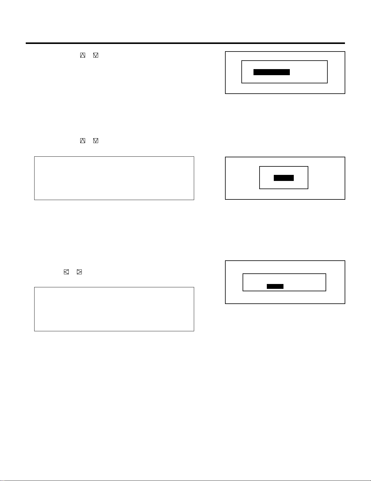
82
5 Use the CURSOR or button to select either “SOUND” or
“PICTURE”, and press the ENTER button.
• The “SOUND MUTE” or “PICTURE MUTE” menu will be
displayed.
6 Use the CURSOR or button to select either “ON” or “OFF”
and then press ENTER.
Items to select
MUTE ON... Mutes a picture and/or sound during switching
signals.
MUTE OFF.. Outputs a picture and/or sound during switching
signals.
7 To complete this, press END.
• Whenever the END button is pressed, the menus will sequence
in this order:
“OPTION” menu → “ADJUST” menu → Source screen
• If the “RETURN USER MODE?” menu appears, use the
CURSOR or button to select either “YES” or “NO” and
then press ENTER.
Items to select
• YES ......... When you try to enter the ADJUST mode the next
time, you will need to re-enter your passcode.
• NO........... When you try to enter the ADJUST mode the next
time, you will not need to re-enter your passcode.
SETTING
RETURN USER MODE?
YES NO
ON
OFF
SIGNAL SWITCHING MUTE
SOUND
PICTURE
ON
OFF
SOUND MUTE
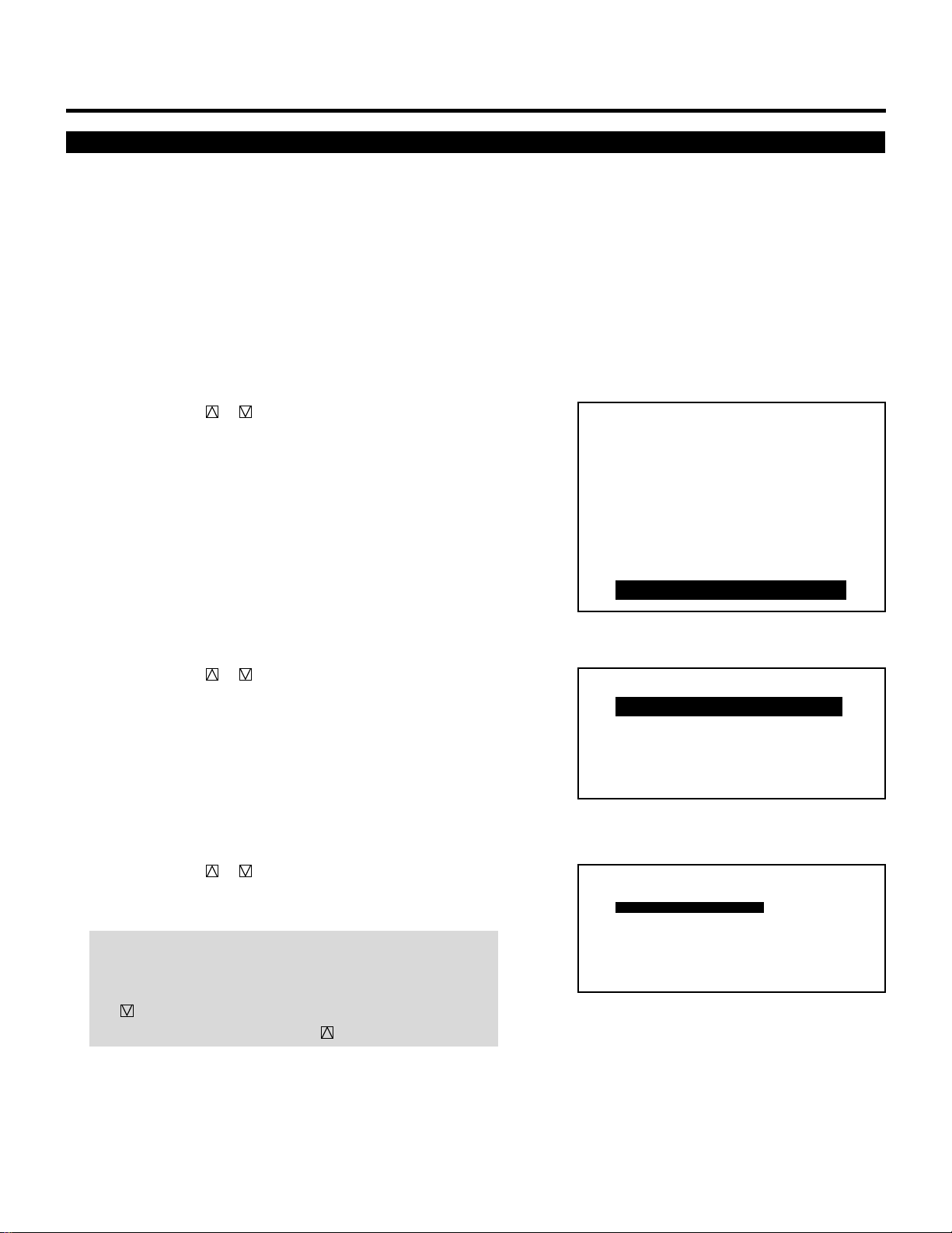
83
SETTING
Automatic Save Feature
This feature allows you to select two ways to store settings; auto-
matically and manually.
After “ENABLE” is selected in the AUTOMATIC DATA STORE
menu, all projector settings are stored in the projector's memory
automatically. To set the AUTOMATIC DATA STORE, proceed as
follows:
1 Press the ADJUST button to display the “ADJUST” menu.
• The projector may ask you to enter your passcode.
See page 52 for the explanation of the PASSCODE section.
2 Use the CURSOR or button to highlight the “9/OPTION”
line and then press ENTER to display the “OPTION” menu. You
can also select the “OPTION” menu directly by pressing the
INPUT “9” button.
• The eighth item is “8/OPTION” in stand alone adjust menu.
3 Use the CURSOR or button to highlight the “1/SETTING
MODE” line. Press ENTER to display the “SETTING MODE”
menu. You can also select the “SETTING MODE” menu directly
by pressing the INPUT “1” button.
4 Use the CURSOR or button to select the “AUTOMATIC
DATA STORE” item on Page 3, then press ENTER to display
the “AUTOMATIC DATA STORE” menu.
NOTE: The SETTING MODE has three menus. The “AUTOMATIC
DATA STORE” item is on the third menu (P03). To access P03
from P01, press and hold down the CTL button then press
the button twice; to return to P01 from P03, press and hold
down the CTL button then press the button twice.
– ADJUST –
1 / SIGNAL ENTRY
2 / FOCUS
3 / ALIGNMENT
4 / CONVERGENCE
5 / WHITE BAL
6 / R,G,B GAIN
7 / HOUR METER
8 / PASSCODE
9 / OPTION
– OPTION –
1 / SETTING MODE
2 / MENU MODE
3 / SEQUENCER
4 / PJ ADDRESS
5 / VERSION
P03 OPTION – SETTING MODE –
DISABLE
DIRECT ENTRY ACCESS DISABLE
ALLFOCUS EDGE MODE
OFF
AUTOMATIC DATA STORE
ASTIG ADJUSTMENT
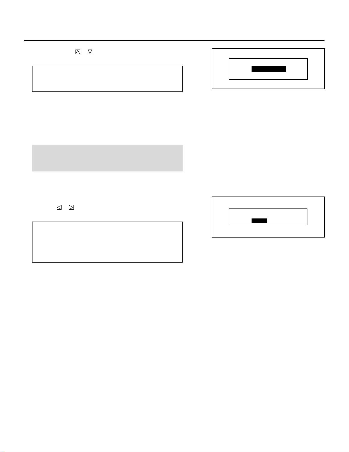
84
5 Use the CURSOR or button to select either “DISABLE” or
“ENABLE” and then press ENTER.
Items to select
• DISABLE.. Projector does not store the settings automatically.
• ENABLE... Projector stores the settings automatically.
Automatic storing data is done when any one of the following
procedures is performed:
• Pressing the END button several times returns the adjustment
screen to the source screen.
• One input is switched to another.
• The projector is turned off.
NOTE: After “DISABLE” is selected in the AUTOMATIC DATA
STORE menu, the settings will not be stored in the memory
unless you select “YES” in the “STORE ?” menu.
6 If the “RETURN USER MODE?” menu appears, use the
CURSOR or button to select either “YES” or “NO” and
press ENTER. This will exit the ADJUST mode.
Items to select
• YES ......... When you try to enter the ADJUST mode the next
time, you will need to re-enter your passcode.
• NO........... When you try to enter the ADJUST mode the next
time, you will not need to re-enter your passcode.
SETTING
RETURN USER MODE?
YES NO
DISABLE
ENABLE
AUTOMATIC DATA STORE
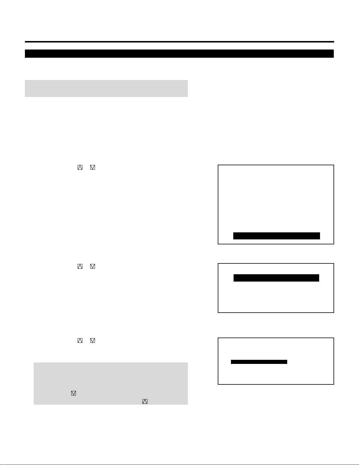
85
SETTING
Direct Entry Access Setting
This feature allows you to switch the current input directly to one of
the registered inputs from NO1 to NO10 in the INPUT LIST.
NOTE: To use this feature, hold down the CTL button and press one
of the INPUT buttons corresponding to the input number.
To set this feature, proceed as follows:
1 Press the ADJUST button to display the “ADJUST” menu.
• The projector may ask you to enter your passcode.
See page 52 for the explanation of the PASSCODE.
2 Use the CURSOR or button to highlight the “9/OPTION”
line. Press ENTER to display the “OPTION” menu. You can also
select the “OPTION” menu directly by pressing the INPUT “9”
button.
• The eighth item is “8/OPTION” in stand alone adjust menu.
3 Use the CURSOR or button to highlight the “1/SETTING
MODE” line. Press ENTER to display the “SETTING MODE”
menu. You can also select the “SETTING MODE” menu directly
by pressing the INPUT “1” button.
4 Use the CURSOR or button to select the “DIRECT ENTRY
ACCESS” item on Page 3, then press ENTER to display the
“DIRECT ENTRY ACCESS” menu.
NOTE: The SETTING MODE has three menus. The “DIRECT
ENTRY ACCESS” item is on the third menu (P03).
To access P03 from P01, press and hold down the CTL button
then press the button twice; to return to P01 from P03, press
and hold down the CTL button then press the button twice.
– ADJUST –
1 / SIGNAL ENTRY
2 / FOCUS
3 / ALIGNMENT
4 / CONVERGENCE
5 / WHITE BAL
6 / R,G,B GAIN
7 / HOUR METER
8 / PASSCODE
9 / OPTION
– OPTION –
1 / SETTING MODE
2 / MENU MODE
3 / SEQUENCER
4 / PJ ADDRESS
5 / VERSION
P03 OPTION – SETTING MODE –
DISABLE
DIRECT ENTRY ACCESS DISABLE
ALLFOCUS EDGE MODE
OFF
AUTOMATIC DATA STORE
ASTIG ADJUSTMENT
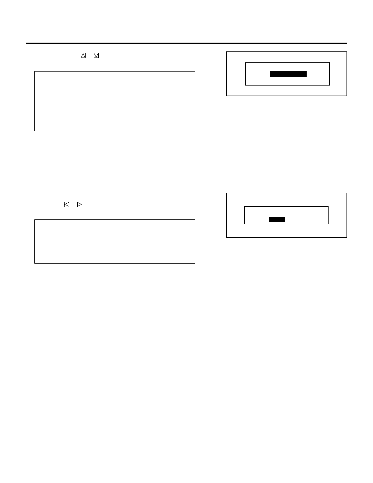
86
5 Use the CURSOR or button to select either “DISABLE” or
“ENABLE” and press ENTER.
Items to select
• DISABLE.. An error message will appear at the bottom of the
screen and the signal is not switched when one of
the INPUT buttons is pressed with CTL.
• ENABLE... The signal is switched to the corresponding signal
when one of the INPUT button is pressed with
CTL.
6 To complete this, press END.
• Whenever the END button is pressed, the menus will sequence
in this order.
“OPTION” menu → “ADJUST” menu → Source screen
• If the RETURN USER MODE ? menu appears, use the
CURSOR or button to select either “YES” or “NO” and
press ENTER. This will exit the ADJUST mode.
Items to select
• YES ......... When you try to enter the ADJUST mode the next
time, you will need to re-enter your passcode.
• NO........... When you try to enter the ADJUST mode the next,
you will not need to re-enter your passcode.
SETTING
RETURN USER MODE?
YES NO
DISABLE
ENABLE
DIRECT ENTRY ACCESS

87
SETTING
ASTIG Adjustment
This function is used to set ASTIG ADJUSTMENT on/off.
NOTE: You can carry out ASTIG CROSS and ASTIG CORNER
adjustment in focus mode only when the ASTIG ADJUSTMENT is
set to on.
To set this function, proceed as follows:
1 Press the ADJUST button to display the “ADJUST” menu.
• The projector may ask you to enter your passcode.
See page 52 for the explanation of the PASSCODE.
2 Use the CURSOR or button to highlight the “9/OPTION”
line. Press ENTER to display the “OPTION” menu. You can also
select the “OPTION” menu directly by pressing the INPUT “9”
button.
• The eighth item is “8/OPTION” in stand alone adjust menu.
3 Use the CURSOR or button to highlight the “1/SETTING
MODE” line. Press ENTER to display the “SETTING MODE”
menu. You can also select the “SETTING MODE” menu directly
by pressing the INPUT “1” button.
4 Use the CURSOR or button to select the “ASTIG ADJUST-
MENT” item on Page 3, then press ENTER to display the
“ASTIG ADJUSTMENT” menu.
NOTE: The SETTING MODE has three menus. The “ASTIG
ADJUSTMENT” item is on the third menu (P03).
To access P03 from P01, press and hold down the CTL button
then press the button twice; to return to P01 from P03, press
and hold down the CTL button then press the button twice.
– ADJUST –
1 / SIGNAL ENTRY
2 / FOCUS
3 / ALIGNMENT
4 / CONVERGENCE
5 / WHITE BAL
6 / R,G,B GAIN
7 / HOUR METER
8 / PASSCODE
9 / OPTION
– OPTION –
1 / SETTING MODE
2 / MENU MODE
3 / SEQUENCER
4 / PJ ADDRESS
5 / VERSION
P03 OPTION – SETTING MODE –
DISABLE
DIRECT ENTRY ACCESS DISABLE
ALLFOCUS EDGE MODE
OFF
AUTOMATIC DATA STORE
ASTIG ADJUSTMENT
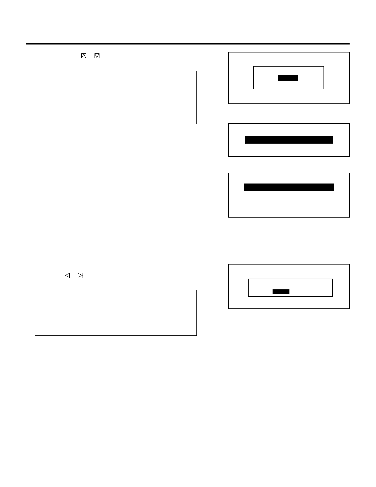
88
SETTING
FOCUS MENU when OFF is selected
OFF
ON
ASTIG ADJUSTMENT
– FOCUS –
1 / CENTER
2 / EDGE ALL
5Use the CURSOR or button to select either “OFF” or “ON”
and press ENTER.
Items to select
• OFF.......... Astig Cross and Astig Corner adjustments are not
possible in FOCUS mode.
• ON........... Astig Cross and Astig Corner adjustments are
included in the focus menu. These adjustments are
possible in FOCUS mode.
6 To complete, press the END button.
• Whenever the END button is pressed, the menus will sequence
in this order:
“OPTION” menu → “ADJUST” menu → Source screen
• If the “RETURN USER MODE?” menu appears, use the
CURSOR or button to select either “YES” or “NO” and
press ENTER. This will exit the ADJUST mode.
Items to select
• YES ......... When you try to enter the ADJUST mode the next
time, you will need to re-enter your passcode.
• NO........... When you try to enter the ADJUST mode the next
time, you will not need to re-enter your passcode.
FOCUS MENU when ON is selected
RETURN USER MODE?
YES NO
– FOCUS –
1 / CENTER
2 / EDGE ALL
3 / ASTIG CROSS
4 / ASTIG CORNER
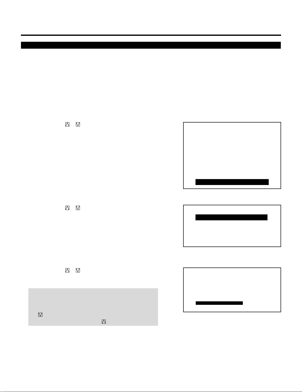
89
SETTING
Focus Edge Mode
This function allows you to set either of two electrical edge focus
modes; one affects all the RGB patterns at the same time and the
other each CRT separately.
To set this, proceed as follows:
1 Press the ADJUST button to display the “ADJUST” menu.
• The projector may ask you to enter your passcode.
See page 52 for the explanation of the PASSCODE.
2 Use the CURSOR or button to highlight the “9/OPTION”
line. Press ENTER to display the “OPTION” menu. You can also
select the “OPTION” menu directly by pressing the INPUT “9”
button.
• The eighth item is “8/OPTION” in stand alone adjust menu.
3 Use the CURSOR or button to highlight the “1/SETTING
MODE” line. Press ENTER to display the “SETTING MODE”
menu. You can also select the “SETTING MODE” menu directly
by pressing the INPUT “1” button.
4 Use the CURSOR or button to select the “FOCUS EDGE
MODE” item on Page 3, then press ENTER to display the
“FOCUS EDGE MODE” menu.
NOTE: The SETTING MODE has three menus. The “FOCUS
EDGE MODE” item is on the third menu (P03). To access P03
from P01, press and hold down the CTL button then press
the button twice; to return to P01 from P03, press and hold
down the CTL button then press the button twice.
– ADJUST –
1 / SIGNAL ENTRY
2 / FOCUS
3 / ALIGNMENT
4 / CONVERGENCE
5 / WHITE BAL
6 / R,G,B GAIN
7 / HOUR METER
8 / PASSCODE
9 / OPTION
– OPTION –
1 / SETTING MODE
2 / MENU MODE
3 / SEQUENCER
4 / PJ ADDRESS
5 / VERSION
P03 OPTION – SETTING MODE –
DISABLE
DIRECT ENTRY ACCESS DISABLE
ALLFOCUS EDGE MODE
OFF
AUTOMATIC DATA STORE
ASTIG ADJUSTMENT
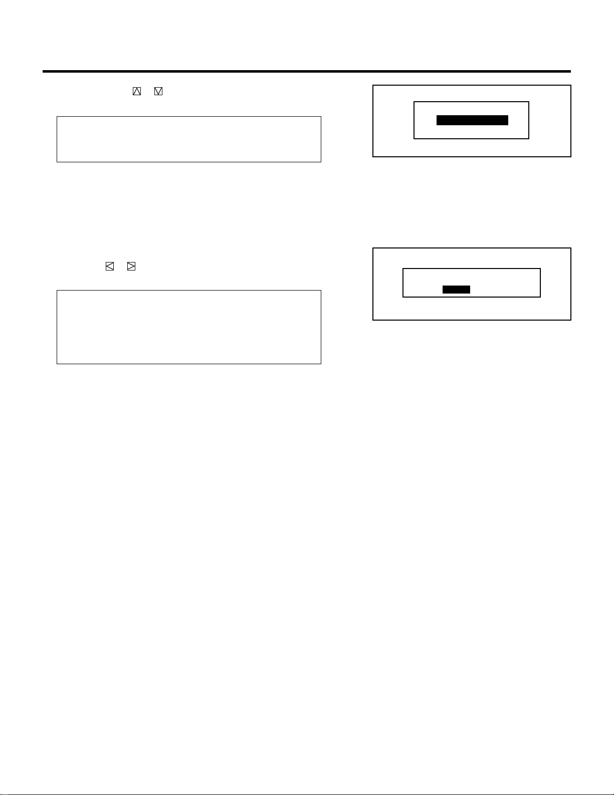
90
5 Use the CURSOR or button to select either “ALL” or
“SEPARATE” and press ENTER.
Items to select
• ALL......................Affects all of the CRTs at the same time
• SEPARATE...........Affects each CRT separately
6 To complete, press the END button.
• Whenever the END button is pressed, the menus will sequence
in this order:
“OPTION” menu → “ADJUST” menu → Source screen
• If the “RETURN USER MODE?” menu appears, use the
CURSOR or button to select either “YES” or “NO” and
press ENTER. This will exit the ADJUST mode.
Items to select
• YES ......... When you try to enter the ADJUST mode the next
time, you will need to re-enter your passcode.
• NO........... When you try to enter the ADJUST mode the next
time, you will not need to re-enter your passcode.
SETTING
ALL
SEPARATE
FOCUS EDGE MODE
RETURN USER MODE?
YES NO
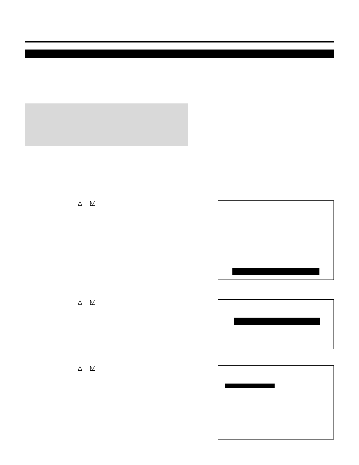
91
On-screen Display Mode Setting
SETTING
There are two modes of operations for the on-screen display. With
AUTO mode, the on-screen display will automatically switch off
after ten seconds. In the MANUAL mode, the display must be
manually turned off with the DISPLAY button on the full function
remote control each time it appears.
NOTE: Pressing DISPLAY with CTL will select the non on-screen
mode; pressing DISPLAY with CTL again will cancel this mode.
Even if the on-screen display may be turned off with CTL and
DISPLAY, any adjustment will still change the projector’s memory
settings.
Proceed as follows:
1 Press the ADJUST button to display the “ADJUST” menu.
• The projector may ask you to enter your passcode.
See page 52 for the explanation of the PASSCODE.
2 Use the CURSOR or button to highlight the “9/OPTION”
line. Press ENTER to display the “OPTION” menu. You can also
select the “OPTION” menu directly by pressing the INPUT “9”
button.
• The eighth item is “8/OPTION” in stand alone adjust menu.
3 Use the CURSOR or button to highlight the “2/MENU
MODE” line. Press ENTER to display the “MENU MODE”
menu. You can also select the “MENU MODE” menu directly by
pressing the INPUT “2” button.
4 Use the CURSOR or button to highlight the “MESSAGE
MODE” item.
Press ENTER to display the “MESSAGE MODE” menu.
– ADJUST –
1 / SIGNAL ENTRY
2 / FOCUS
3 / ALIGNMENT
4 / CONVERGENCE
5 / WHITE BAL
6 / R,G,B GAIN
7 / HOUR METER
8 / PASSCODE
9 / OPTION
– OPTION –
1 / SETTING MODE
2 / MENU MODE
3 / SEQUENCER
4 / PJ ADDRESS
5 / VERSION
OPTION - MENU MODE -
MESSAGE MODE
MESSAGE COLOR
DATE, TIME DISPLAY
DATE, TIME PRESET
DATE : MM/DD/YY
TIME : 24HOUR
AUTO 10 SEC
COLOR
DATE : ON
DAY : OFF
TIME : ON
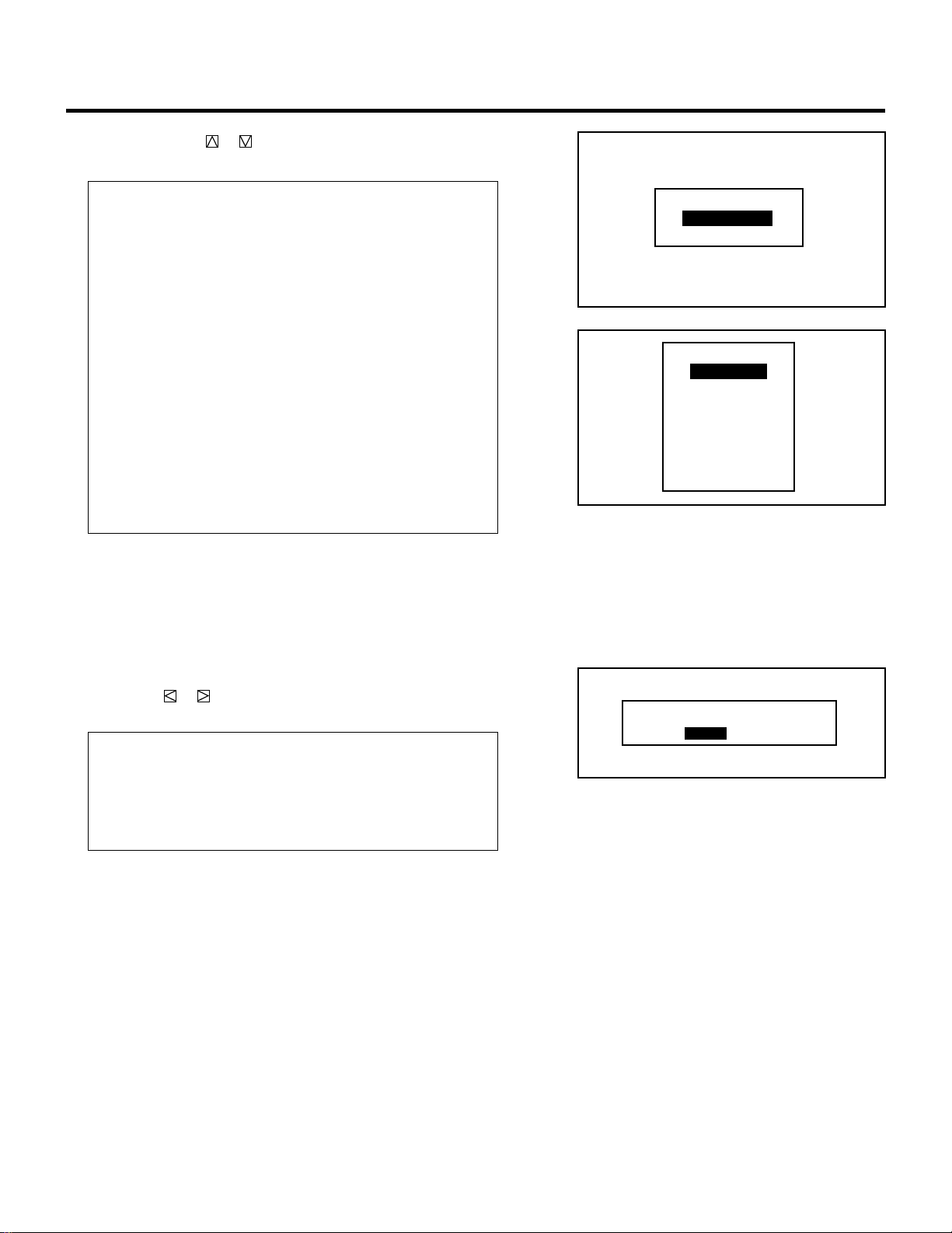
92
5 Use the CURSOR or button to select either “AUTO” or
“MANUAL“ and press ENTER.
Items to select
• AUTO....... The on-screen menu display appears when the
buttons on the remote control, or the controls on
the rear panel are pressed. The on-screen display
will turn off at a preselected time.
The OFF TIME is specified in seconds up to a
maximum of 10 seconds.
Select your desired time (3-10 seconds) from the
OFF TIME menu.
• MANUAL . The on-screen menu display appears when the
buttons on the remote control, or the controls on
the rear panel are pressed. The display will be
turned on and off whenever the DISPLAY button is
pressed. If no button operation is made for 20
minutes or more, the on-screen message will
automatically turn off.
6 To end this mode, press the END button.
• When the END button is pressed, the menus will sequence in
this order:
“OPTION” menu → “ADJUST” menu → Source screen
• If the “RETURN USER MODE?” menu appears, use the
CURSOR or button to select either “YES” or “NO” and
press ENTER. This will exit the ADJUST mode.
Items to select
• YES ......... When you try to enter the ADJUST mode the next
time, you will need to re-enter your passcode.
• NO........... When you try to enter the ADJUST mode the next
time, you will not need to re-enter your passcode.
SETTING
RETURN USER MODE?
YES NO
AUTO
MANUAL
MESSAGE MODE
3 SEC
4 SEC
5 SEC
6 SEC
7 SEC
8 SEC
9 SEC
10 SEC
OFF TIME?
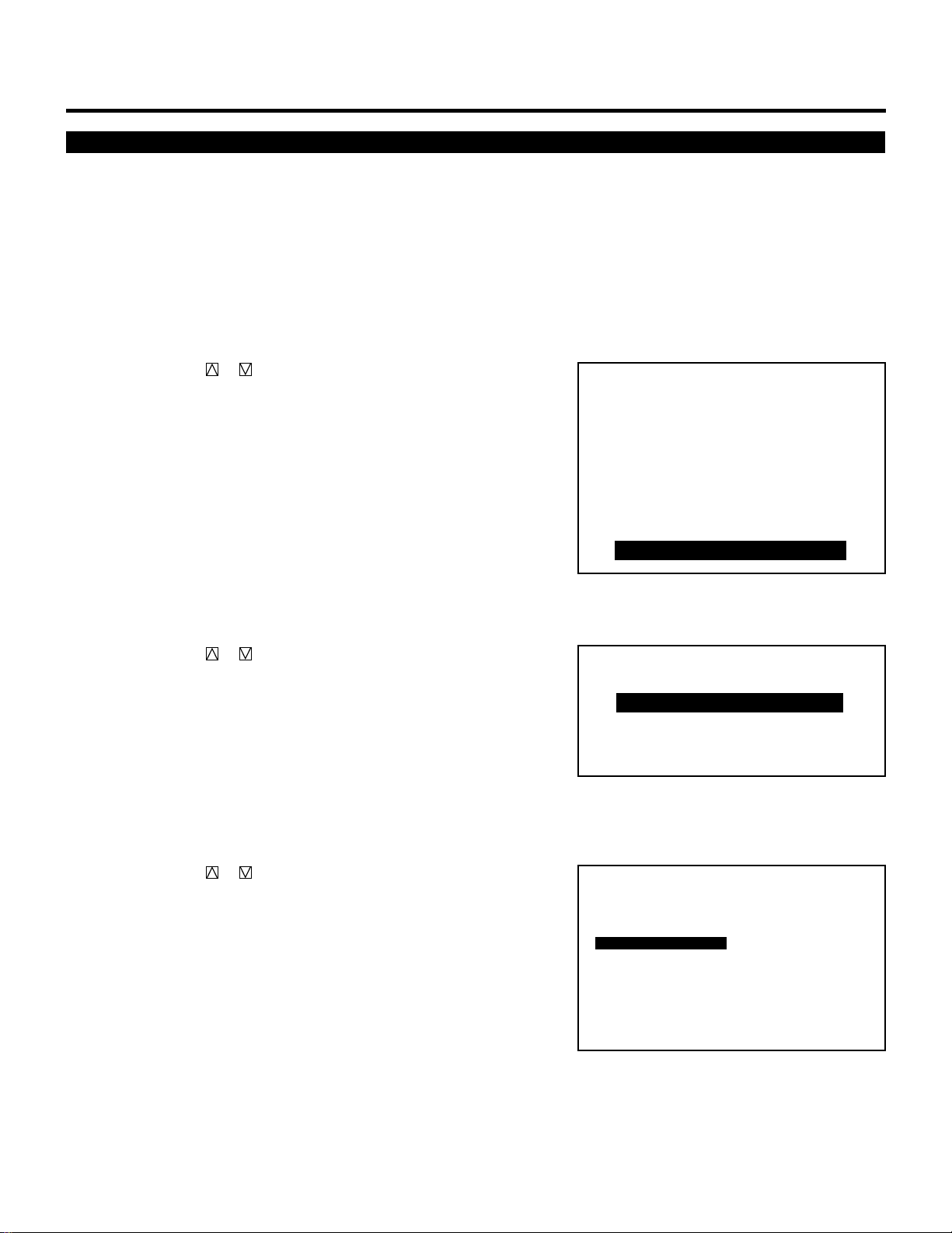
93
SETTING
On-screen Display Color Setting
You can select two color modes (full color, or green only) for the
color of the on-screen display such as menus, or messages.
Proceed as follows:
1 Press the ADJUST button to display the “ADJUST” menu.
• The projector may ask you to enter your passcode.
See page 52 for the explanation of the PASSCODE.
2 Use the CURSOR or button to highlight the “9/OPTION”
line. Press ENTER to display the “OPTION” menu. You can also
select the “OPTION” menu directly by pressing the INPUT “9”
button.
• The eighth item is “8/OPTION” in stand alone adjust menu.
3 Use the CURSOR or button to highlight the “2/MENU
MODE” line. Press ENTER to display the “MENU MODE”
menu. You can also select the “MENU MODE” menu directly by
pressing the INPUT “2” button.
4 Use the CURSOR or button to highlight the “MESSAGE
COLOR” item.
Press ENTER to display the “MESSAGE COLOR” menu.
– ADJUST –
1 / SIGNAL ENTRY
2 / FOCUS
3 / ALIGNMENT
4 / CONVERGENCE
5 / WHITE BAL
6 / R,G,B GAIN
7 / HOUR METER
8 / PASSCODE
9 / OPTION
– OPTION –
1 / SETTING MODE
2 / MENU MODE
3 / SEQUENCER
4 / PJ ADDRESS
5 / VERSION
OPTION - MENU MODE -
MESSAGE MODE
MESSAGE COLOR
DATE, TIME DISPLAY
DATE, TIME PRESET
DATE : MM/DD/YY
TIME : 24HOUR
AUTO 10 SEC
COLOR
DATE : ON
DAY : OFF
TIME : ON
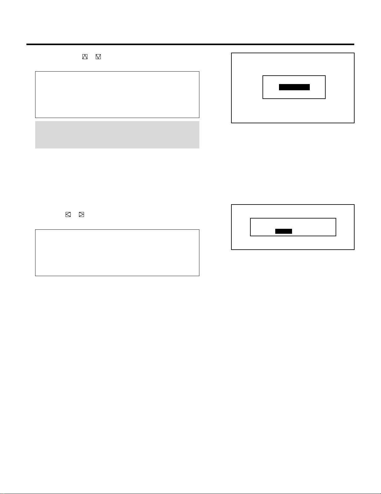
94
5 Use the CURSOR or button to select either “COLOR” or
“GREEN“ and press ENTER.
Items to select
• COLOR .... The on-screen characters will be displayed in
color.
• GREEN..... The on-screen characters will be displayed only in
green.
NOTE: It is recommended, if the on-screen message interferes
with the display image in the “COLOR” mode, that you select
“GREEN”.
6 To end this mode, press the END button.
• Whenever the END button is pressed, the menus will sequence
in this order:
“OPTION” menu → “ADJUST” menu → Source screen
• If the “RETURN USER MODE?” menu appears, use the
CURSOR or button to select either “YES” or “NO” and
press ENTER. This will exit the ADJUST mode.
Items to select
• YES ......... When you try to enter the ADJUST mode the next
time, you will need to re-enter your passcode.
• NO........... When you try to enter the ADJUST mode the next
time, you will not need to re-enter your passcode.
SETTING
COLOR
GREEN
MESSAGE COLOR
RETURN USER MODE?
YES NO
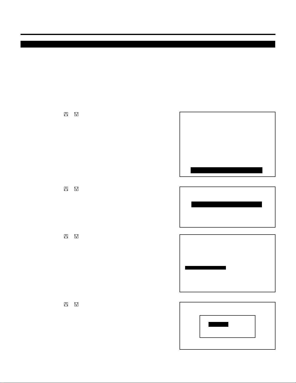
95
SETTING
Date, Time Display Setting
The current year, month, date and time are displayed on the top of
the screen.
Proceed as follows:
1 Press the ADJUST button to display the “ADJUST” menu.
• The projector may ask you to enter your passcode.
See page 52 for the explanation of the PASSCODE.
2 Use the CURSOR or button to highlight the “9/OPTION”
line. Press ENTER to display the “OPTION” menu. You can also
select the “OPTION” menu directly by pressing the INPUT “9”
button.
• The eighth item is “8/OPTION” in stand alone adjust menu.
3 Use the CURSOR or button to highlight the “2/MENU
MODE” line. Press ENTER to display the “MENU MODE”
menu. You can also select the “MENU MODE” menu directly by
pressing the INPUT “2” button.
4 Use the CURSOR or button to highlight the “DATE, TIME,
DISPLAY” item. Press ENTER to display the “DATE, TIME
DISPLAY” menu.
5 Use the CURSOR or button to select any one of the three
items: DATE, DAY, and TIME. Then press ENTER.
– ADJUST –
1 / SIGNAL ENTRY
2 / FOCUS
3 / ALIGNMENT
4 / CONVERGENCE
5 / WHITE BAL
6 / R,G,B GAIN
7 / HOUR METER
8 / PASSCODE
9 / OPTION
– OPTION –
1 / SETTING MODE
2 / MENU MODE
3 / SEQUENCER
4 / PJ ADDRESS
5 / VERSION
OPTION - MENU MODE -
MESSAGE MODE
MESSAGE COLOR
DATE, TIME DISPLAY
DATE, TIME PRESET
DATE : MM/DD/YY
TIME : 24HOUR
AUTO 10 SEC
COLOR
DATE : ON
DAY : OFF
TIME : ON
DATE
DAY
TIME
DATE,TIME DISPLAY
ON
OFF
ON
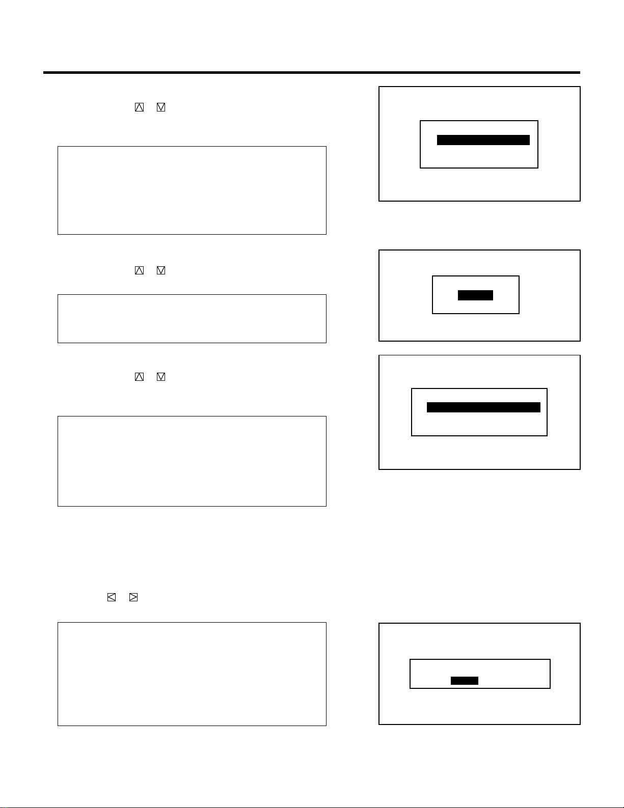
96
m When selecting “DATE”
Use the CURSOR or button to select any one of the three
formats: MM/DD/YY, MONTH/ DD/YY, or OFF from the
“DATE DISPLAY” menu and press ENTER.
Items to select
• MM/DD/YY ..........Is the date in month/day-of-month/year
format.
• MONTH/DD/YY....Is the date in month (not in Arabic numer-
als)/day-of-month/year format.
• OFF......................Does not display the date.
m When selecting “DAY”
Use the CURSOR or button to select either “ON” or “OFF”
from the “DAY DISPLAY” menu and press ENTER.
Items to select
• ON.......................Displays the day of the week
• OFF......................Does not display the day of the week
m When selecting “TIME”
Use the CURSOR or button to select any one of the three
items: HH/MM/SS AM/PM, HH/MM/SS 24 HOUR, or OFF
from the “TIME DISPLAY” menu and press ENTER.
Items to select
•
HH:MM:SS AM/PM
....Is the time in hours/minutes/seconds/am/
pm. format
•
HH:MM:SS 24 HOUR
.....Is the time in hours/minutes/seconds/24-
hour format
• OFF......................Does not display the time.
6 To end this mode, press END.
• Whenever the END button is pressed, the menus will sequence
in this order:
“OPTION” menu → “ADJUST” menu → Source screen
• If the “RETURN USER MODE?” menu appears, use the
CURSOR or button to select either “YES” or “NO” and
press ENTER. This will exit the ADJUST mode.
Items to select
• YES .....................When you try to enter the ADJUST mode
the next time, you will need to re-enter your
passcode.
• NO.......................When you try to enter the ADJUST mode
the next time, you will not need to re-enter
your passcode.
SETTING
RETURN USER MODE?
YES NO
ON
OFF
DAY DISPLAY
HH:MM:SS AM/PM
HH:MM:SS 24HOUR
OFF
TIME DISPLAY
MM/DD/YY
MONTH/DD/YY
OFF
DATE DISPLAY
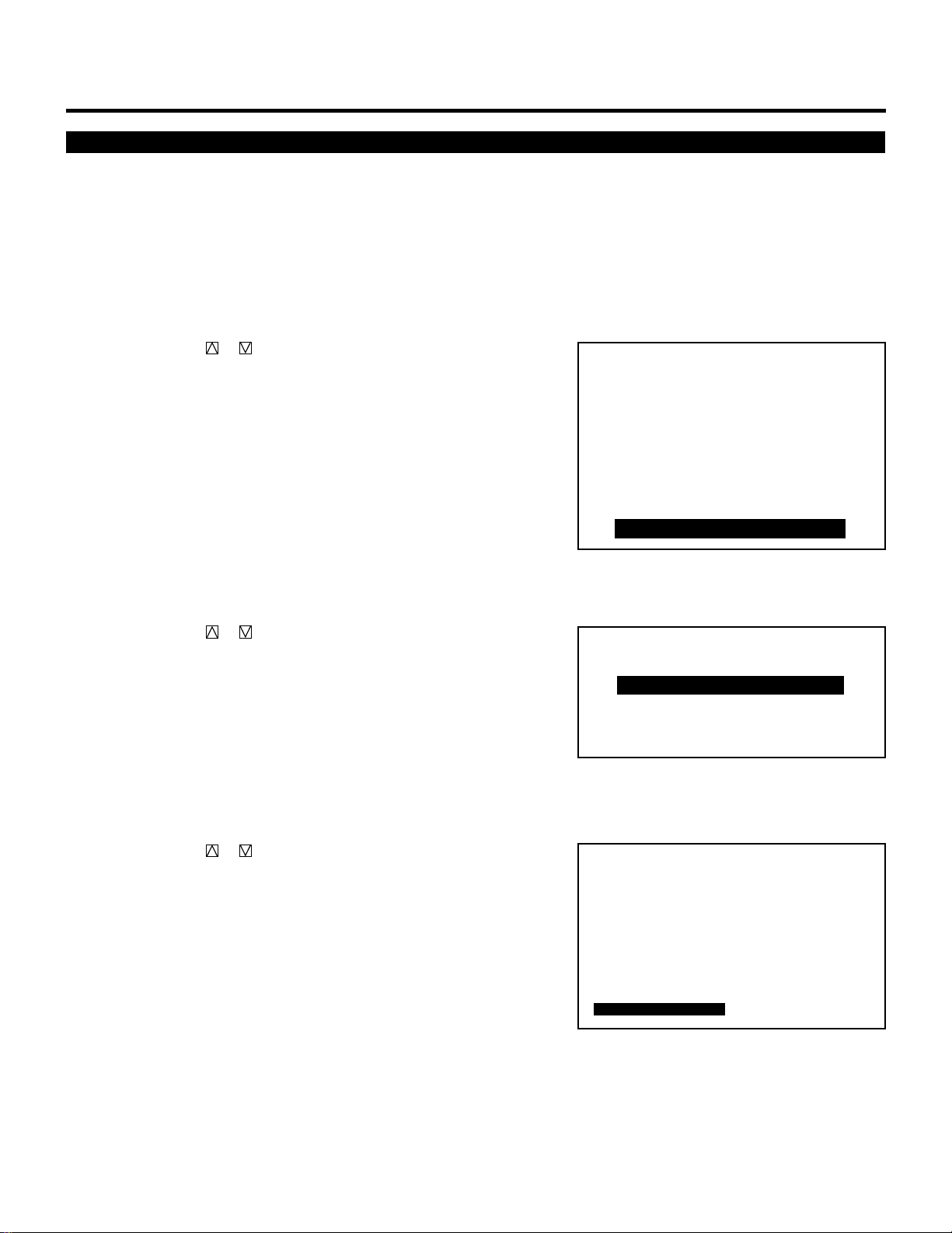
97
SETTING
Entering Date and Time
You can enter the year, date and time to display them on the screen.
Proceed as follows:
1 Press the ADJUST button to display the “ADJUST” menu.
• The projector may ask you to enter your passcode.
See page 52 for the explanation of the PASSCODE.
2 Use the CURSOR or button to highlight the “9/OPTION”
line. Press ENTER to display the “OPTION” menu. You can also
select the “OPTION” menu directly by pressing the INPUT “9”
button.
• The eighth item is “8/OPTION” in stand alone adjust menu.
3 Use the CURSOR or button to highlight the “2/MENU
MODE” line. Press ENTER to display the “MENU MODE”
menu. You can also select the “MENU MODE” menu directly by
pressing the INPUT “2” button.
4 Use the CURSOR or button to highlight the “DATE, TIME
PRESET” item. Press ENTER to display the “DATE, TIME
PRESET” menu.
– ADJUST –
1 / SIGNAL ENTRY
2 / FOCUS
3 / ALIGNMENT
4 / CONVERGENCE
5 / WHITE BAL
6 / R,G,B GAIN
7 / HOUR METER
8 / PASSCODE
9 / OPTION
– OPTION –
1 / SETTING MODE
2 / MENU MODE
3 / SEQUENCER
4 / PJ ADDRESS
5 / VERSION
OPTION - MENU MODE -
MESSAGE MODE
MESSAGE COLOR
DATE, TIME DISPLAY
DATE, TIME PRESET
DATE : MM/DD/YY
TIME : 24HOUR
AUTO 10 SEC
COLOR
DATE : ON
DAY : OFF
TIME : ON
98
SETTING
5 Use INPUT buttons to enter the year, month, day, hour, minute,
and second and press ENTER.
• Pressing the END button will turn off the “DATE, TIME
PRESET” screen and the screen will return to the “MENU
MODE” menu.
• If you made an error in entering data, press the END button to
return to the “MENU MODE” menu, then start again.
6 To end this mode, press END.
• Whenever the END button is pressed, the menus will sequence
in this order:
“OPTION” menu → “ADJUST” menu → Source screen
• If the “RETURN USER MODE?” menu appears, use the
CURSOR or button to select either “YES” or “NO” and
press ENTER. This will exit the ADJUST mode.
Items to select
• YES ......... When you try to enter the ADJUST mode the next
time, you will need to re-enter your passcode.
• NO........... When you try to enter the ADJUST mode the next
time, you will not need to re-enter your passcode.
NOTE: The projector has a built-in clock. The clock will keep
working for about three days after the main power is turned off.
If the main power is not supplied to the projector for three days
or more, the built-in clock may reset. If the built-in clock resets,
set the date and time again. The built-in clock will not reset
while in the standby condition.
RETURN USER MODE?
YES NO
DATE
TIME
DATE,TIME PRESET
(MM/DD/YY)
__/__/__(MON)
(HH:MM:SS)
__:__:__
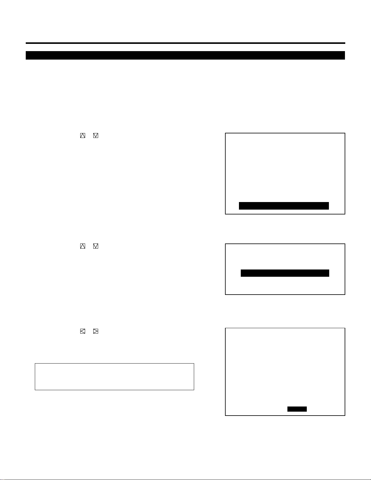
99
SETTING
Auto Sequence Setting
You can program the projector to change sources.
To do this proceed as follows:
1 Press the ADJUST button to display the “ADJUST” menu.
• The projector may ask you to enter your passcode.
See page 52 for the explanation of the PASSCODE.
2 Use the CURSOR or button to highlight the “9/OPTION”
line. Press ENTER to display the “OPTION” menu. You can also
select the “OPTION” menu directly by pressing the INPUT “9”
button.
• The eighth item is “8/OPTION” in stand alone adjust menu.
3 Use the CURSOR or button to highlight the “3/SE-
QUENCER” line. Press ENTER to display the “SEQUENCER”
menu. You can also select the “SEQUENCER” menu directly by
pressing the INPUT “3” button.
• The “SEQUENCER” screen will be displayed.
4 Use the CURSOR or button to select the “EDIT” and press
ENTER.
• This will bring you to the “EDIT” mode, and a program line is
highlighted.
Items to select
• START..... Executes the program.
• EDIT ........ Corrects or creates the program data.
– ADJUST –
1 / SIGNAL ENTRY
2 / FOCUS
3 / ALIGNMENT
4 / CONVERGENCE
5 / WHITE BAL
6 / R,G,B GAIN
7 / HOUR METER
8 / PASSCODE
9 / OPTION
– OPTION –
1 / SETTING MODE
2 / MENU MODE
3 / SEQUENCER
4 / PJ ADDRESS
5 / VERSION
OPTION - SEQUENCER -
P01
NO
01
02
03
04
05
06
07
08
09
10
INPUT
M-10
M-02
M-01
WAIT
M-01
WAIT
LOOP
M-02
P-OFF
P-ON
S-01
S-02
S-02
S-01
03 COUNT 05
S-02
TIME
12:00:00
14:00:00
00:10:00
00:20:00
15:50:00
18:00:00
09:00:00
SMTWTFS
2VVVVV2
2VVVVV2
2VVVVV2
2VVVVV2
2VVVVV2
2VVVVV2
2VVVVV2
START EDIT
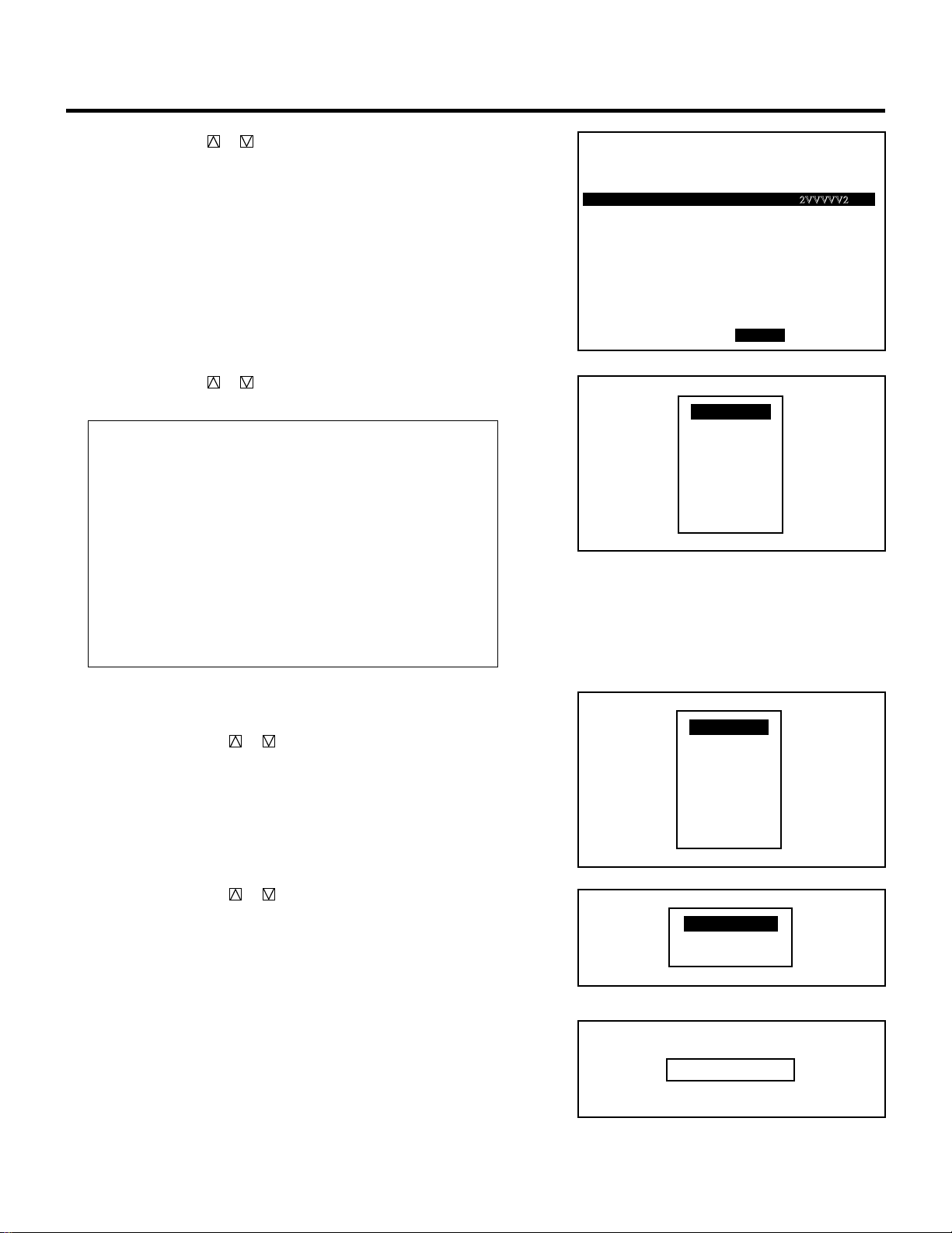
100
SETTING
OPTION - SEQUENCER -
P01
NO
01
02
03
04
05
06
07
08
09
10
INPUT
M-10
M-02
M-01
WAIT
M-01
WAIT
LOOP
M-02
P-OFF
P-ON
S-01
S-02
S-02
S-01
03 COUNT 05
S-02
TIME
12:00:00
14:00:00
00:10:00
00:20:00
15:50:00
18:00:00
09:00:00
SMTWTFS
2VVVVV2
2VVVVV2
2VVVVV2
2VVVVV2
2VVVVV2
2VVVVV2
2VVVVV2
START EDIT
INPUT
WAIT
GOTO
LOOP
P-ON
P-OFF
INSERT
DELETE
5 Use the CURSOR or button to highlight the line to be input
and press ENTER.
• The Program menu is displayed.
6 Use the CURSOR or button to highlight the desired item
and press ENTER.
Items to select
• INPUT...... Enter new data.
• WAIT ....... Retains the current condition for a specified time.
• GOTO....... Jumps to the selected line
• LOOP....... Executes the LOOP operation.
• P-ON ....... Programs to turn on the power at the desired time.
• P-OFF ...... Programs to turn off the power at the desired time.
• INSERT.... Inserts the selected line and moves down the
following lines.
• DELETE ... Deletes the selected line and moves up the
following lines.
m Selecting “INPUT”
When using in stand alone application:
1) Use the CURSOR or button to select “INPUT” and press
ENTER.
• The “VIDEO/RGB/S-VIDEO” terminal menu is displayed.
2) Use the CURSOR or button to select either “VIDEO”,
“RGB”, or “S-VIDEO” and press ENTER.
• The “TIME” input screen is displayed.
3) Enter the starting time using INPUT buttons and press
ENTER.
• Type the time in hours (24 hours), minutes, and seconds.
• If you have made an error in the input of numbers, press the
END button to return to the “VIDEO/RGB/S-VIDEO”
terminal menu then start from step 2).
• The “WEEK SELECT” screen will appear.
VIDEO
RGB
S-VIDEO
INPUT
WAIT
GOTO
LOOP
P-ON
P-OFF
INSERT
DELETE
TIME __:__:__
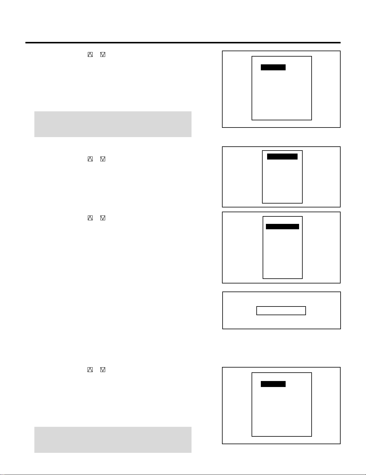
101
SETTING
4) Use the CURSOR or button to select any day of the
week, then select either “YES” or “NO” with ENTER.
• When “DAILY” selected, the entire week is changed to
“YES”.
• When “END” is selected, the current setting is saved.
• To return to Step 3), press the END button. In that case, the
changed setting is invalid.
NOTE: Typing 99:99:99 in the time input menu will execute the
program immediately. (See the examples in the “WAIT” section
on page 103)
When using with a single ISS-6010/ISS-6010G Switcher:
1) Use the CURSOR or button to select “INPUT” and press
ENTER.
• The “MASTER” menu will be displayed.
2) Use the CURSOR or button to select the input slot
number of the Switcher and press ENTER.
• The “TIME” input screen will be displayed.
3) Enter the starting time using INPUT buttons and press
ENTER.
• Type the time in hours (24 hours), minutes, and seconds.
• If you have made an error in the input of numbers, press the
END button to return to the “MASTER” menu then start
from step 2).
• The “WEEK SELECT” screen will appear.
4) Use the CURSOR or button to select any day of the
week, then select either “YES” or “NO” with ENTER.
• When “DAILY” selected, the entire week is changed to
“YES”.
• When “END” is selected, the current setting is saved.
• To return to Step 3), press the END button. In that case, the
changed setting is invalid.
NOTE: Typing 99:99:99 in the time input menu will execute the
program immediately. (See the examples in the “WAIT” section
on page 103)
DAILY
SUN
MON
TUE
WEN
THU
FRI
SAT
END
WEEK SELECT
NO
YES
YES
YES
YES
YES
NO
INPUT
WAIT
GOTO
LOOP
P-ON
P-OFF
INSERT
DELETE
SLOT–01
SLOT–02
SLOT–03
SLOT–04
SLOT–05
SLOT–06
SLOT–07
SLOT–08
SLOT–09
SLOT–10
MASTER
TIME __:__:__
DAILY
SUN
MON
TUE
WEN
THU
FRI
SAT
END
WEEK SELECT
NO
YES
YES
YES
YES
YES
NO
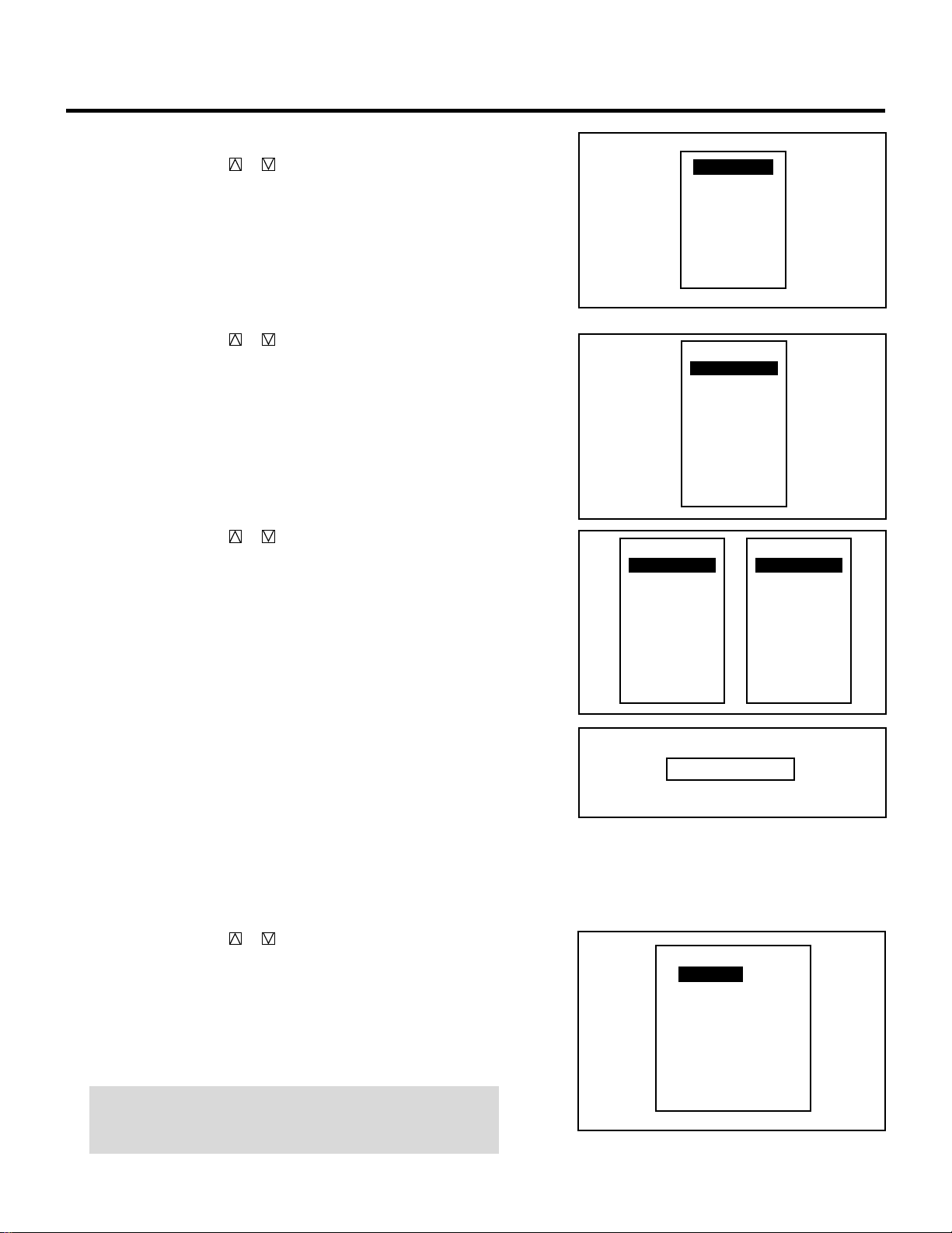
102
SETTING
When using with two or more ISS-6010/ISS-6010G Switchers:
1) Use the CURSOR or button to select “INPUT” and press
ENTER.
• The “MASTER” and “SLAVE” menu will be displayed.
2) Use the CURSOR or button to select the input slot
number of the master Switcher from the “MASTER” menu
and press ENTER.
3) Use the CURSOR or button to select the input slot
number of the slave Switcher from the “SLAVE” menu and
press ENTER.
• The “TIME” input screen will be displayed.
4) Enter the starting time using INPUT buttons and press
ENTER.
• Type the time in hours (24 hours), minutes, and seconds.
• If you have made an error in the input of numbers, press the
END button to return to the “SLAVE” menu then start from
step 2).
• The “WEEK SELECT” screen will appear.
5) Use the CURSOR or button to select any day of the
week, then select either “YES” or “NO” with ENTER.
• When “DAILY” selected, the entire week is changed to
“YES”.
• When “END” is selected, the current setting is saved.
• To return to Step 4), press the END button. In that case, the
changed setting is invalid.
NOTE: Typing 99:99:99 in the time input menu will execute the
program immediately. (See the example in the following “WAIT”
section.)
INPUT
WAIT
GOTO
LOOP
P-ON
P-OFF
INSERT
DELETE
SLOT–01
SLOT–02
SLOT–03
SLOT–04
SLOT–05
SLOT–06
SLOT–07
SLOT–08
SLOT–09
SLOT–10
MASTER
SLOT–01
SLOT–02
SLOT–03
SLOT–04
SLOT–05
SLOT–06
SLOT–07
SLOT–08
SLOT–09
SLOT–10
MASTER
SLOT–01
SLOT–02
SLOT–03
SLOT–04
SLOT–05
SLOT–06
SLOT–07
SLOT–08
SLOT–09
SLOT–10
SLAVE
TIME __:__:__
DAILY
SUN
MON
TUE
WEN
THU
FRI
SAT
END
WEEK SELECT
NO
YES
YES
YES
YES
YES
NO
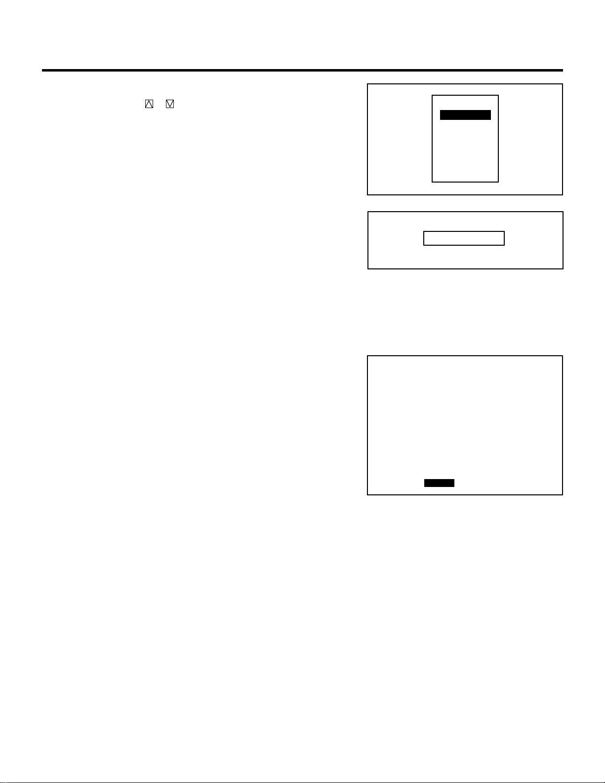
103
SETTING
m Selecting “WAIT”
1) Use the CURSOR or button to select “WAIT” and press
ENTER.
• The “TIME” input screen will be displayed.
2) Type the waiting time using the INPUT buttons and press
ENTER.
• Type the time in hours, minutes, and seconds.
• If you have made an error in the input of numbers, press the
END button to return to the Program menu on step 1), then
start again.
Example:
When the following program is set, the display as shown on the
right will appear:
First line:Select VIDEO, then type “99:99:99” in the TIME input
screen, then select “DAILY” in the WEEK SELECT menu for
“INPUT”.
Second line:Select type “00:20:00” in the TIME input screen for
“WAIT”.
Third line:Type “99:99:99”, then select “DAILY” for “P-OFF”.
When this program starts, the input signal will change to VIDEO
immediately. Then, the current condition will be retained for 20
minutes.
Finally, the power will be turned off.
The “WAIT” function is used to execute the command immedi-
ately.
INPUT
WAIT
GOTO
LOOP
P-ON
P-OFF
INSERT
DELETE
TIME __:__:__
OPTION - SEQUENCER -
P01
NO
01
02
03
04
05
06
07
08
09
10
INPUT
VIDEO
WAIT
P-OFF
TIME
00:20:00
SMTWTFS
VVVVVVV
VVVVVVV
START EDIT

104
SETTING
m Selecting “GOTO”
1) Use the CURSOR or button to select “GOTO” and press
ENTER.
• The “GOTO” input screen will be displayed.
2) Enter the scan number line to which you want to jump to
using the INPUT button and press ENTER.
• If you have made an error, press END to return to the
Program menu, then start again.
• The “SEQUENCER” screen will be restored to its last
setting.
m Selecting “LOOP”
1) Use the CURSOR or button to select “LOOP” and press
ENTER.
• The “LOOP/COUNT” input screen will be displayed.
2) Enter the number of the destination line (LOOP) and the
number of the loop times (COUNT) in this order using the
INPUT button and press ENTER.
• If you have made an error, press END to return to the
Program menu, then start again.
• The “SEQUENCER” screen will be restored to its last
setting.
INPUT
WAIT
GOTO
LOOP
P-ON
P-OFF
INSERT
DELETE
GOTO __
INPUT
WAIT
GOTO
LOOP
P-ON
P-OFF
INSERT
DELETE
LOOP __ COUNT __
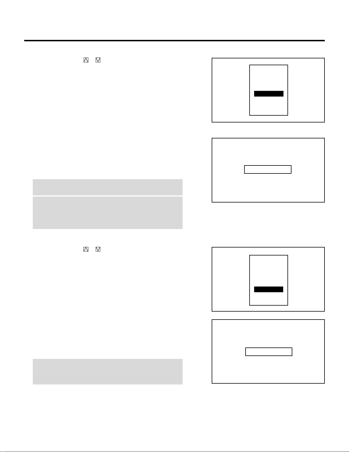
105
SETTING
m Selecting “P-ON”
1) Use the CURSOR or button to select “P-ON” and press
ENTER.
• The POWER ON input screen will be displayed.
2) Enter the POWER ON TIME you wish to turn on the projec-
tor using INPUT buttons and press ENTER.
• Type the time in hours (24 hours), minutes and seconds.
• If you made an error, press END to return to the Program
menu, then start again.
NOTE 1: Typing 99:99:99 in the time input menu will execute
the program immediately.
NOTE 2: The P-ON command is available only when the
projector is off (in the standby condition).
The P-ON command is ignored if set in the first line. In this
case, the program will start its execution from the second line.
m Selecting “P-OFF”
1) Use the CURSOR or button to select “P-OFF” and press
ENTER.
• The POWER OFF input screen will be displayed.
2) Enter the POWER OFF TIME you wish to turn on the
projector using INPUT buttons and press ENTER.
• Type the time in hours (24 hours), minutes and seconds.
• If you made an error, press END to return to the Program
menu, then start again.
NOTE: Typing 99:99:99 in the time input menu will execute the
program immediately. (See the example in the “WAIT” section
on page 103)
INPUT
WAIT
GOTO
LOOP
P-ON
P-OFF
INSERT
DELETE
TIME __:__:__
INPUT
WAIT
GOTO
LOOP
P-ON
P-OFF
INSERT
DELETE
TIME __:__:__
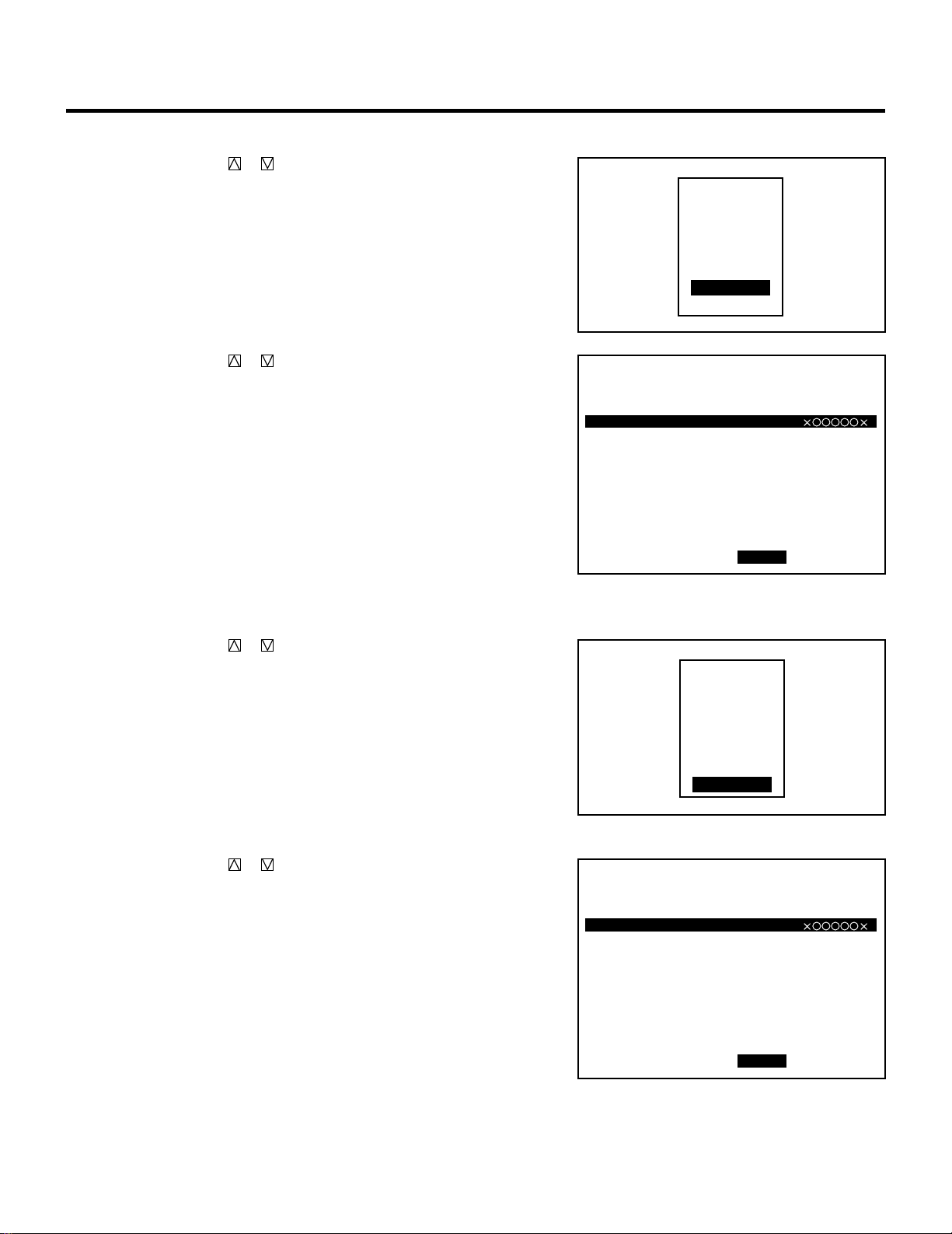
106
m Selecting “INSERT”
1) Use the CURSOR or button to select “INSERT” and
press ENTER.
2) Use the CURSOR or button to select where you wish to
insert a vacant line and press ENTER.
• The highlighted line will be switched to a vacant line and
the original line(s) will be moved down.
m Selecting “DELETE”
1) Use the CURSOR or button to select “DELETE” and
press ENTER.
2) Use the CURSOR or button to select the line you wish
to delete and press ENTER.
• The selected line will be deleted and the following line(s)
will be moved up.
SETTING
INPUT
WAIT
GOTO
LOOP
P-ON
P-OFF
INSERT
DELETE
OPTION - SEQUENCER -
P01
NO
01
02
03
04
05
06
07
08
09
10
INPUT
M-10
M-02
M-01
WAIT
M-01
WAIT
LOOP
M-02
P-OFF
P-ON
S-01
S-02
S-02
S-01
03 COUNT 05
S-02
TIME
12:00:00
14:00:00
00:10:00
00:20:00
15:50:00
18:00:00
09:00:00
SMTWTFS
2VVVVV2
2VVVVV2
2VVVVV2
2VVVVV2
2VVVVV2
2VVVVV2
2VVVVV2
START EDIT
INPUT
WAIT
GOTO
LOOP
P-ON
P-OFF
INSERT
DELETE
OPTION - SEQUENCER -
P01
NO
01
02
03
04
05
06
07
08
09
10
INPUT
M-10
M-02
M-01
WAIT
M-01
WAIT
LOOP
M-02
P-OFF
P-ON
S-01
S-02
S-02
S-01
03 COUNT 05
S-02
TIME
12:00:00
14:00:00
00:10:00
00:20:00
15:50:00
18:00:00
09:00:00
SMTWTFS
2VVVVV2
2VVVVV2
2VVVVV2
2VVVVV2
2VVVVV2
2VVVVV2
2VVVVV2
START EDIT
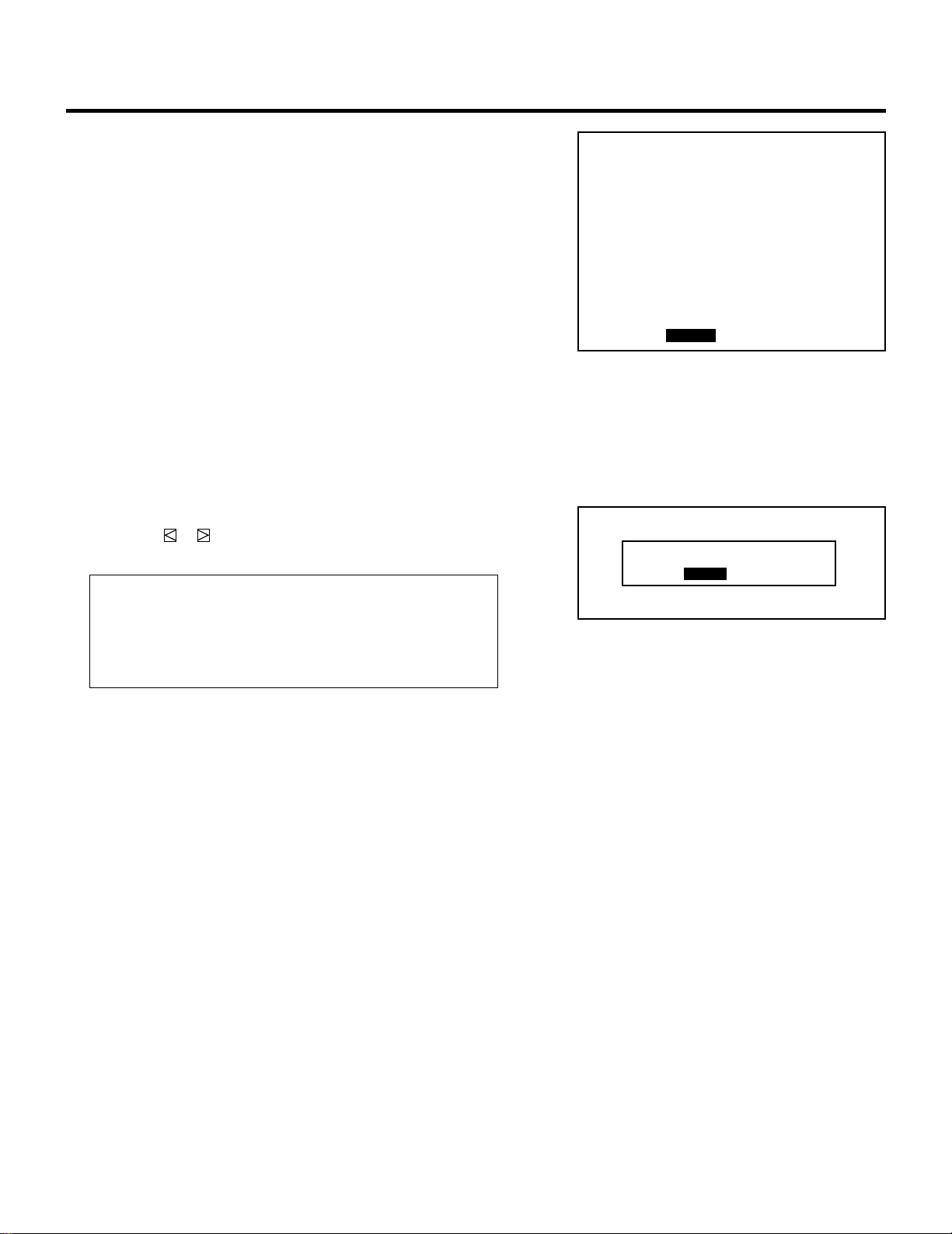
107
7 Pressing the END button will exit the “EDIT” mode.
Select “START” and press ENTER to execute the program.
• The “*EXECUTING NO. XX*” will appear during program
execution. When the program is finished, the “*SEQUENCER
END*” message will appear for about five seconds.
To cancel the program, hold down the CTL button then press
END. The “*SEQUENCER MANUAL END*” will appear for
about five seconds.
8 To end this mode, press the END button.
• Whenever the END button is pressed, the menus will sequence
in this order:
“SEQUENCER” screen (No highlighted line) → “ADJUST”
menu → Source screen
• If the “RETURN USER MODE?” menu appears, use the
CURSOR or button to select either “YES” or “NO” and
then press ENTER. This will exit the ADJUST mode.
Items to select
• YES ......... When you try to enter the ADJUST mode the next
time, you will need to re-enter your passcode.
• NO........... When you try to enter the ADJUST mode the next
time, you will not need to re-enter your passcode.
SETTING
RETURN USER MODE?
YES NO
OPTION - SEQUENCER -
P01
NO
01
02
03
04
05
06
07
08
09
10
INPUT
M-10
M-02
M-01
WAIT
M-01
WAIT
LOOP
M-02
P-OFF
P-ON
S-01
S-02
S-02
S-01
03 COUNT 05
S-02
TIME
12:00:00
14:00:00
00:10:00
00:20:00
15:50:00
18:00:00
09:00:00
SMTWTFS
2VVVVV2
2VVVVV2
2VVVVV2
2VVVVV2
2VVVVV2
2VVVVV2
2VVVVV2
START EDIT
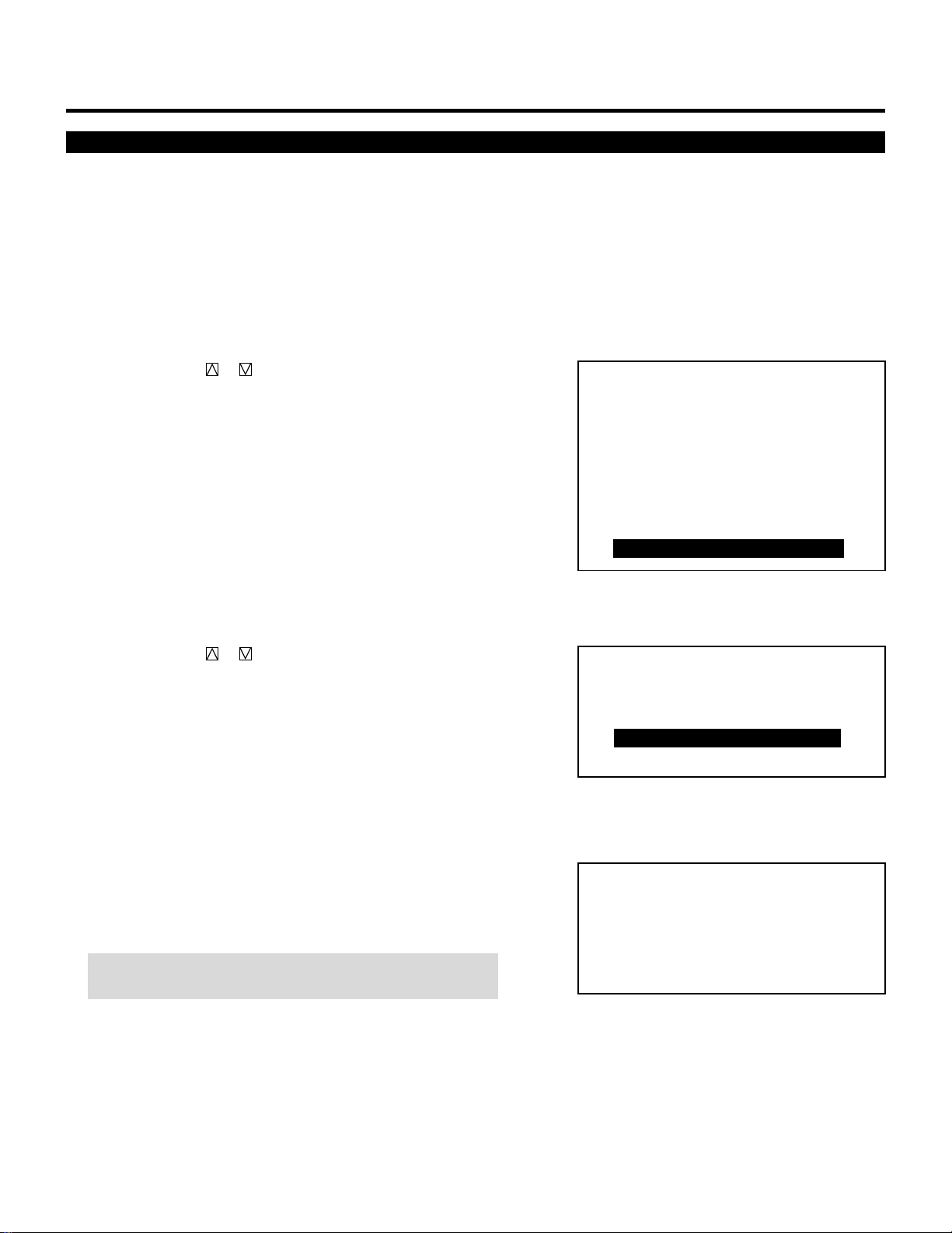
108
SETTING
Address Setting
Each projector needs its own unique address in the case of a serial
connection of projectors. Up to 64 addresses can be set.
Proceed as follows:
1 Press the ADJUST button to display the “ADJUST” menu.
• The projector may ask you to enter your passcode.
See page 52 for the explanation of the PASSCODE.
2 Use the CURSOR or button to highlight the “9/OPTION”
line. Press ENTER to display the “OPTION” menu. You can also
select the “OPTION” menu directly by pressing the INPUT “9”
button.
• The eighth item is “8/OPTION” in stand alone adjust menu.
3 Use the CURSOR or button to highlight the “4/PJ AD-
DRESS” line. Press ENTER to display the “ADDRESS” screen.
You can also select the “ADDRESS” screen directly by pressing
the INPUT “4” button.
4 Enter the address number using the INPUT button and press
ENTER.
• If you have made a mistake, press END to return to the “OP-
TION” menu, then start again.
NOTE: Enter the address number “01” when only one projector
is used.
– ADJUST –
1 / SIGNAL ENTRY
2 / FOCUS
3 / ALIGNMENT
4 / CONVERGENCE
5 / WHITE BAL
6 / R,G,B GAIN
7 / HOUR METER
8 / PASSCODE
9 / OPTION
– OPTION –
1 / SETTING MODE
2 / MENU MODE
3 / SEQUENCER
4 / PJ ADDRESS
5 / VERSION
-PJ ADDRESS-
01 (01-64)
OPTION
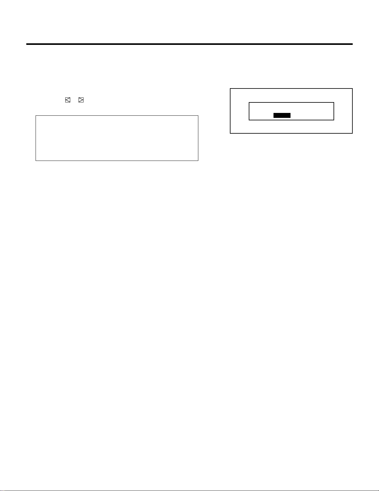
109
SETTING
5 To complete, press the END button.
• Whenever the END button is pressed, the menus will sequence
in this order:
“OPTION” menu → “ADJUST” menu → Source screen
• If the “RETURN USER MODE?” menu appears, use the
CURSOR or button to select either “YES” or “NO” and
press ENTER. This will exit the ADJUST mode.
Items to select
• YES ......... When you try to enter the ADJUST mode the next
time, you will need to re-enter your passcode.
• NO........... When you try to enter the ADJUST mode the next
time, you will not need to re-enter your passcode.
RETURN USER MODE?
YES NO
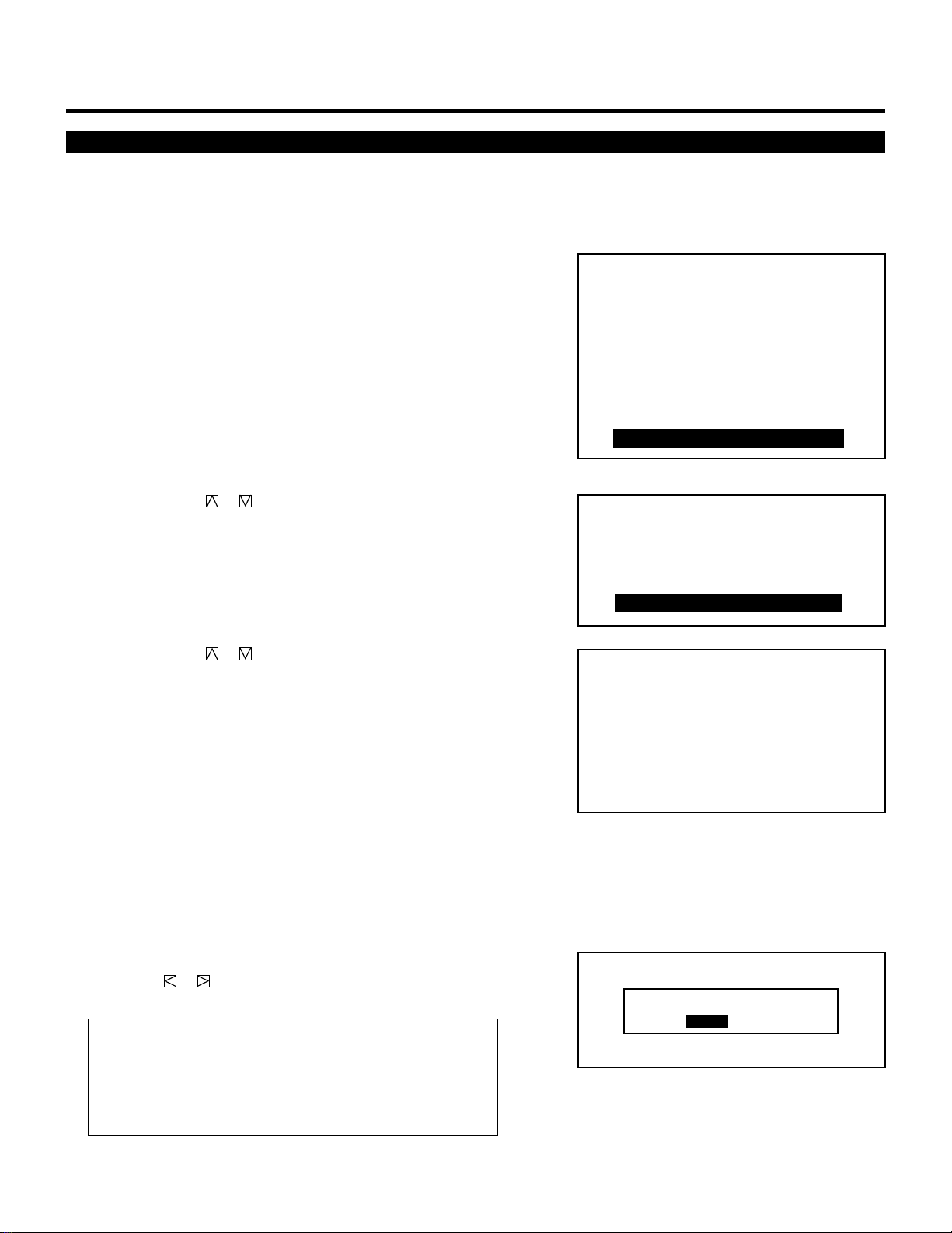
110
SETTING
Projector Version Number
This function lets you know the version for hardware and software
used in the projector.
To view the Version number, proceed as follows:
1 Press the ADJUST button to display the “ADJUST” menu.
• The projector may ask you to enter your passcode.
See page 52 for the explanation of the PASSCODE.
2 Use the CURSOR or button to highlight the “9/OPTION”
line. Press ENTER to display the “OPTION” menu. You can also
select the “OPTION” menu directly by pressing the INPUT “9”
button.
• The eighth item is “8/OPTION” in stand alone adjust menu.
3 Use the CURSOR or button to highlight the “5/VERSION”
line. Press ENTER to display the “VERSION NUMBER” menu.
You can also select the “VERSION NUMBER” menu directly by
pressing the INPUT “5” button.
• You will know what version number your applications software
and the projector are.
• The “POINT” and “SWITCHER” items are available only when
the point convergence is set to the ENABLE and the connect
condition to the SW 1 or 2 LEVEL.
4 To complete this, press END.
• Whenever the END button is pressed, the menus will sequence
in this order:
“OPTION” menu → “ADJUST” menu → Source screen
• If the “RETURN USER MODE?” menu appears, use the
CURSOR or button to select either “YES” or “NO” and
press ENTER. This will exit the ADJUST mode.
Items to select
• YES ......... When you try to enter the ADJUST mode the next
time, you will need to re-enter your passcode.
• NO........... When you try to enter the ADJUST mode the next
time, you will not need to re-enter your passcode.
– ADJUST –
1 / SIGNAL ENTRY
2 / FOCUS
3 / ALIGNMENT
4 / CONVERGENCE
5 / WHITE BAL
6 / R,G,B GAIN
7 / HOUR METER
8 / PASSCODE
9 / OPTION
– OPTION –
1 / SETTING MODE
2 / MENU MODE
3 / SEQUENCER
4 / PJ ADDRESS
5 / VERSION
RETURN USER MODE?
YES NO
OPTION
- VERSION NUMBER -
HARDWARE VERSION
SOFTWARE VERSION
3.00
3.00
3.00
3.00
2.00
3.00
2.00
BIOS
APPLICATION
DATA
SUB-CPU
POINT
SWITCHER
111
SETTING
Step Through Menu for Projector Set up
The “ADJUST” mode has a STEP THROUGH MENU. This is the
mode which the projector automatically guides you through the
adjustment items. The order is based on the Set-Up Procedure shown
on page 31.
Proceed as follows:
1 Press and hold the CTL button then press the ADJUST button to
display the “STEP THROUGH MENU”.
• The projector may ask you to enter your passcode. See page 52
for the explanation of the PASSCODE.
• At the start “1/SIGNAL ENTRY” is highlighted.
2 Press ENTER at this moment to change the screen to the SIG-
NAL ENTRY menu. Perform a signal entry.
• See the Signal Entry section on page 16 thru 23 for more
details.
3 After finishing the Signal Entry, press END and the “STEP
THROUGH MENU” will return.
• The item “SIGNAL ENTRY” is flagged with an asterisk. The
highlighted indicator moves to the next item “FOCUS”.
• Similarly, other finished items are flagged with an asterisk. The
highlight moves to the next item in order.
• To go back to the previous item or to skip items, use the
CURSOR or button to select the item.
4 To stop this mode, press END.
• The display will return to the source screen.
• If the “RETURN USER MODE?” menu appears, use the
CURSOR or button to select either “YES” or “NO” and
press ENTER. This will exit the ADJUST mode.
Items to select
• YES ......... When you try to enter the ADJUST mode the next
time, you will need to re-enter your passcode.
• NO........... When you try to enter the ADJUST mode the next
time, you will not need to re-enter your passcode.
STEP THROUGH MENU
1 / SIGNAL ENTRY
2 / FOCUS
3 / ALIGNMENT
4 / STATIC
5 / CONVERGENCE
6 / WHITE BAL
7 / R,G,B GAIN
8 / POSITION
9 / PICTURE
:ADJUSTMENT FINISH
∗
-FOCUS-
1 / CENTER
2 / EDGE ALL
STEP THROUGH MENU
1 / SIGNAL ENTRY
2 / FOCUS
3 / ALIGNMENT
4 / STATIC
5 / CONVERGENCE
6 / WHITE BAL
7 / R,G,B GAIN
8 / POSITION
9 / PICTURE
:ADJUSTMENT FINISH
∗
RETURN USER MODE?
YES NO
114
123456
12345
6
12345
6
12345
6
12345
6
12345
6
123456
TIMING CHARTS.
Pre-set Signals
The following signals have been set by factory.
m MultiSync 6PG XTRA m MultiSync 9PG XTRA
P01 INPUT SELECT
STANDALONE
NO
01
02
03
04
05
06
07
08
09
10
INPUT
VIDEO
VIDEO
VIDEO
VIDEO
RGB
S-VIDEO
S-VIDEO
NAME
NTSC3.58
NTSC4.43
PAL
SECAM
VGA480
NTSC3.58
PAL
DATE
P01 INPUT SELECT
STANDALONE
NO
01
02
03
04
05
06
07
08
09
10
INPUT
VIDEO
VIDEO
VIDEO
VIDEO
RGB
S-VIDEO
S-VIDEO
NAME
NTSC3.58
NTSC4.43
PAL
SECAM
VGA480
NTSC3.58
PAL
DATE
P06 INPUT SELECT
STANDALONE
NO
51
52
53
54
55
56
57
58
59
60
INPUT
VIDEO
VIDEO
RGB
RGB
RGB
RGB
RGB
RGB
RGB
NAME
NTSC3.58
PAL
VGA350
VGA480
MAC2
IDTV
HDTV
VESA800
VESA1024
DATE
P06 INPUT SELECT
STANDALONE
NO
51
52
53
54
55
56
57
58
59
60
INPUT
VIDEO
VIDEO
RGB
RGB
RGB
RGB
RGB
RGB
RGB
RGB
NAME
NTSC3.58
PAL
VGA350
VGA480
MAC2
IDTV
HDTV
VESA800
VESA1024
QUADRA
DATE
P07 INPUT SELECT
STANDALONE
NO
61
62
63
64
65
66
67
68
69
70
INPUT NAME DATE
P07 INPUT SELECT
STANDALONE
NO
61
62
63
64
65
66
67
68
69
70
INPUT
RGB
NAME
HP-WS
DATE
P08 INPUT SELECT
STANDALONE
NO
71
72
73
74
75
76
77
78
79
80
INPUT
VIDEO
RGB
NAME
NTSC(F)
VGA(F)
DATE
P08 INPUT SELECT
STANDALONE
NO
71
72
73
74
75
76
77
78
79
80
INPUT
VIDEO
RGB
NAME
NTSC(F)
VGA(F)
DATE
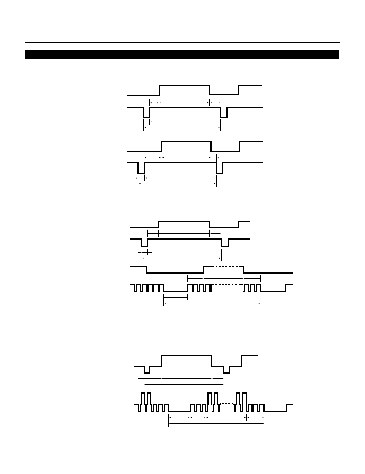
115
TIMING CHART
Input Signal Refernce Chart
VIDEO
C
D
E
A
B
VIDEO
C
D
E
A
B
VIDEO
C
D
E
A
B
VIDEO
C
DE
A
B
C
DE
A
B
VIDEO
CD
E
A
B
VIDEO
HORIZONTAL
VERTICAL
HORIZONTAL
VERTICAL
HORIZONTAL
VERTICAL
Separate Sync.
Composite Sync.
Composite Sync. & Video (Sync. on Green)
Sync. Polarity: Positive/Negative
Sync. Polarity: Positive/Negative
Sync. Polarity: Negative

116
TIMING CHART
Input Signal Timing
H µs
V ms
H µs
V ms
H µs
V ms
H µs
V ms
H µs
V ms
H µs
V ms
H µs
V ms
H µs
V ms
A
31.8
14.3
31.8
14.3
31.78
16.67
28.57
15
31.8
16.7
14.64
13.342
20.8
13.887
20.677
16.667
B
3.8
0.06
3.8
0.06
2.76
0.64
2.12
0.09
3.8
0.06
1.30
0.044
2.4
0.124
2.092
0.124
C
1.6
1.72
1.6
0.89
1.6
0.77
3.17
1.11
1.6
0.79
1.32
0.574
1.28
0.479
2.462
0.600
D
26.1
11.53
26.1
13.19
26.29
15.14
21.16
13.71
26.1
15.79
11.56
12.68
16.00
12.510
15.754
15.880
E
0.3
0.99
0.3
0.16
1.13
0.12
2.12
0.09
0.3
0.06
0.46
0.044
1.12
0.722
0.369
0.062
Polarity
`
1
1
`
1
1
1
1
IBM VGA 350
IBM VGA 400
IDTV
Macintosh II
IBM VGA 480
Macintosh Quadra
VESA 8002600
(72 Hz)
VESA 10242768
(60 Hz)
• IBM CGA, EGA and VGA are registered trademarks of International Business Machines Corporation.
• Apple is a registered trademark of Apple Computer Inc. Macintosh II and Macintosh Quadra are trademarks of Apple Computer
Inc.
• VESA is an abbreviation for Video Electronics Standards Association.
52
Entering Passcode
To prevent any unauthorized operation or mis-adjustment, the
projector is equipped with a passcode option. If your passcode has
not been entered correctly, the “ADJUST” menu will not be dis-
played. When the ADJUST button is pressed, and no passcode has
been entered, the “PASSCODE?” screen is displayed. Enter your
passcode.
To do this, proceed as follows:
1 Press the ADJUST button.
• The “PASSCODE?” screen is displayed.
2 Enter the four digit passcode you have already registered by
using the “1” through “0” buttons.
1) Each time you press the INPUT button, an asterisk appears
under the “PASSCODE?” message.
2) After you have finished entering the four digit passcode, press
ENTER.
NOTE: If you have made an error, press the NORMAL button to
delete the asterisk “∗”. Then re-enter the correct passcode. To
delete all the entered digits, hold down the CTL button then
press the NORMAL button.
3) If the entered passcode is correct, the “ADJUST” menu is
displayed.
NOTE: If the passcode is not correct, the “WARNING DIFFER-
ENT PASSCODE!!” message is displayed and you are required
to enter the correct passcode.
3 Proceed to each adjustment and setting.
PASSCODE?
∗∗∗∗
123456
12345
6
12345
6
12345
6
12345
6
12345
6
123456
PASSCODE.
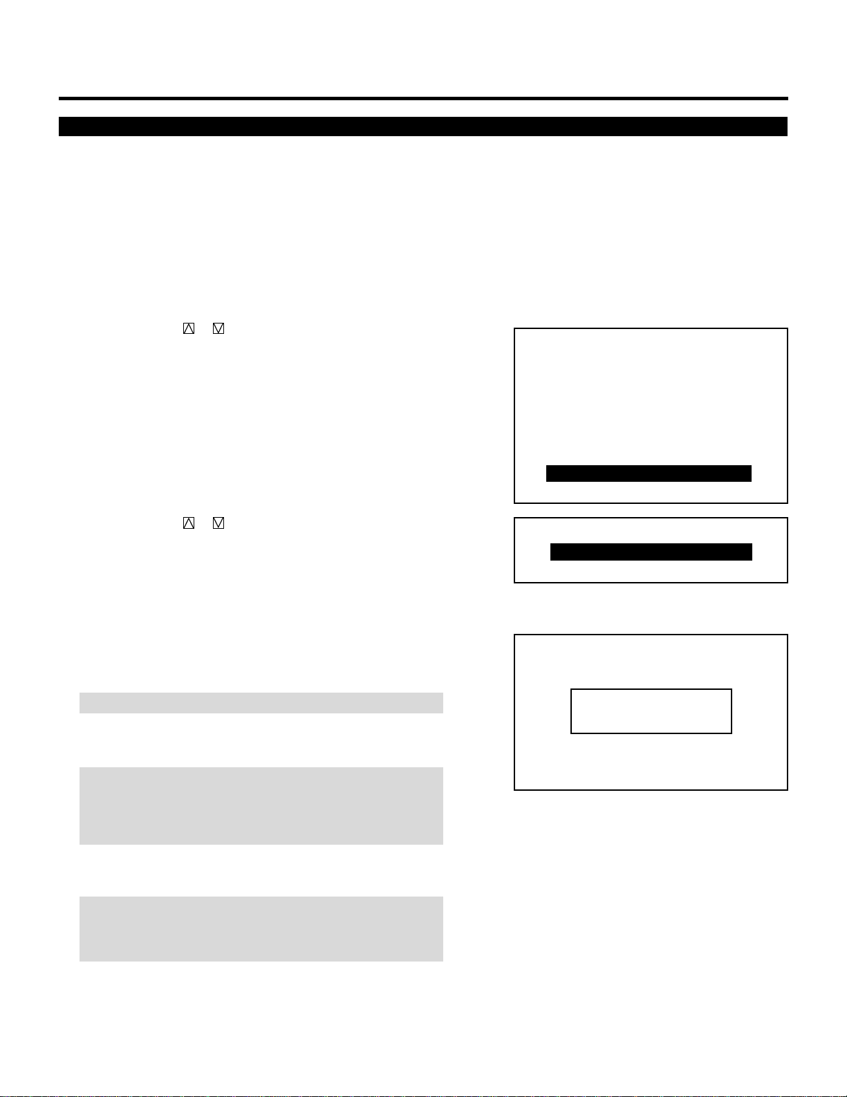
53
PASSCODE
Registering Passcode
When the projector is shipped from the factory, no passcode is
registered. If you want to use the passcode option, you must register
a passcode.
To register a new passcode, proceed as follows:
1 Press the ADJUST button.
• The “ADJUST” menu will be displayed.
2 Use the CURSOR or button to highlight the “8/
PASSCODE” line. Press ENTER to display the “PASSCODE”
menu. You can also select the “PASSCODE” menu directly by
pressing the INPUT “8” button.
• The seventh item is “7/PASSCODE” in stand alone adjust
menu.
3 Use the CURSOR or button to select “ENTRY”. Press
ENTER to display the “NEW PASSCODE?” menu. You can also
select the “NEW PASSCODE?” menu directly by pressing the
INPUT “1” button.
4 Enter a four digit passcode using the “1” through “0” buttons.
1) Each time you press the INPUT button, an asterisk will
appear under the “NEW PASSCODE?” message.
NOTE: ”0000" and “9999” cannot be used as a passcode.
2) Once you have finished entering your four digit passcode,
press ENTER to store the code.
NOTE: If you have made an error, press the NORMAL button to
delete the asterisk “∗”. Then re-enter the correct passcode.
To delete all the entered digits, hold down the CTL button then
press the NORMAL button.
3) If the passcode has been entered correctly, the “CONFIRM
NEW PASSCODE?” menu will be displayed.
NOTE: If the passcode is not entered correctly, the “WARNING
PASSCODE!!” message will be displayed. You will be required
to enter the passcode correctly.
– ADJUST –
1 / SIGNAL ENTRY
2 / FOCUS
3 / ALIGNMENT
4 / CONVERGENCE
5 / WHITE BAL
6 / R,G,B GAIN
7 / HOUR METER
8 / PASSCODE
9 / OPTION
– PASSCODE –
1 / ENTRY
2 / DISABLE
––––
NEW PASSCODE?
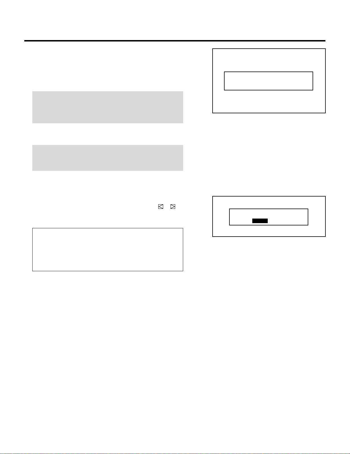
54
PASSCODE
5 Enter the new passcode again.
1) Each time you press the INPUT button, an asterisk will
appear under the “CONFIRM NEW PASSCODE?” message.
2) Once you have finished entering the new four digit passcode,
press ENTER.
NOTE: If you have made an error, press the NORMAL button to
delete the asterisk “∗”. Then re-enter the correct passcode.
To delete all the entered digits, hold down the CTL button then
press the NORMAL button.
3) If the entered passcode is correct, the “CHANGE
PASSCODE COMPLETE!!” message will be displayed.
NOTE: If the passcode is not correct, the “WARNING DIFFER-
ENT PASSCODE!!” message will be displayed. You are required
to enter the new passcode correctly.
6 To complete, press the END button.
• When the END button is pressed once, the “RETURN USER
MODE?” menu will be displayed. Use the CURSOR or
button to select either “YES” or “NO” and then press ENTER.
This will exit the ADJUST mode.
Items to select
• YES ......... When you try to enter the ADJUST mode again,
you will need to re-enter your passcode.
• NO........... When you try to enter the ADJUST mode again,
you will not need to re-enter your passcode.
RETURN USER MODE?
YES NO
––––
CONFIRM NEW PASSCODE?
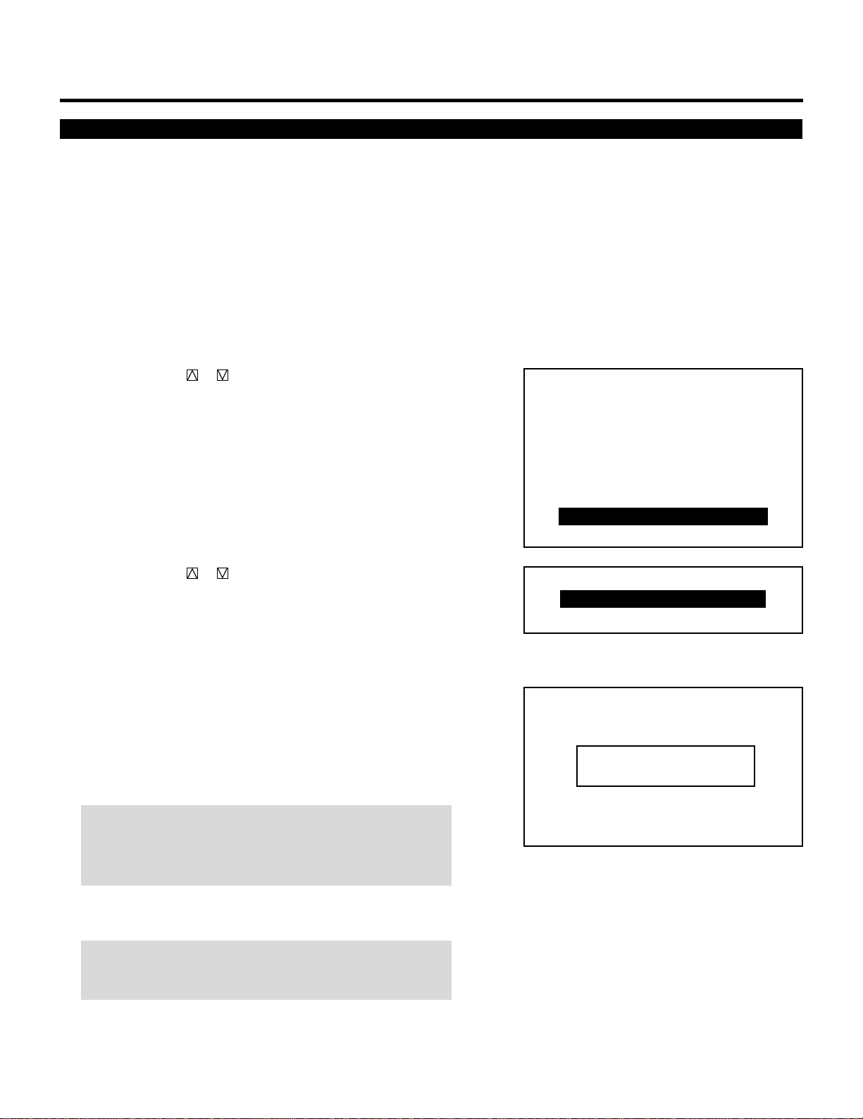
55
PASSCODE
Changing Your Passcode
To change your passcode, proceed as follows:
1 Press the ADJUST button.
• The “PASSCODE?” screen will be displayed.
2 Enter the four digit current passcode using the “1” through “0”
buttons. Press ENTER.
• The “ADJUST” menu will be displayed.
3 Use the CURSOR or button to highlight the “8/
PASSCODE” line. Press ENTER to display the “PASSCODE”
menu. You can also select the “PASSCODE” menu directly by
pressing the INPUT “8” button.
• The seventh item is “7/PASSCODE” in stand alone adjust
menu.
4 Use the CURSOR or button to select “1/ENTRY”. Press
ENTER to display the “CURRENT PASSCODE?” menu. You
can also select the “CURRENT PASSCODE?” menu directly by
pressing the INPUT “1” button.
5 Enter the four digit passcode (the current passcode) using the “1”
through “0” buttons.
1) Each time you press the INPUT button, an asterisk will
appear under the “CURRENT PASSCODE?” message.
2) Once you have finished entering the four digit passcode, press
ENTER.
NOTE: If you have made an error, press the NORMAL button to
delete the asterisk “∗”. Then re-enter the correct passcode. To
delete all the entered digits, hold down the CTL button then
press the NORMAL button.
3) If the entered passcode is correct, the “NEW PASSCODE?”
screen will be displayed.
NOTE: If the passcode is not correct, the “WARNING DIFFER-
ENT PASSCODE!!” message is displayed. You will be required
to enter the correct current passcode.
– ADJUST –
1 / SIGNAL ENTRY
2 / FOCUS
3 / ALIGNMENT
4 / CONVERGENCE
5 / WHITE BAL
6 / R,G,B GAIN
7 / HOUR METER
8 / PASSCODE
9 / OPTION
– PASSCODE –
1 / ENTRY
2 / DISABLE
CURRENT PASSCODE?
∗∗∗∗
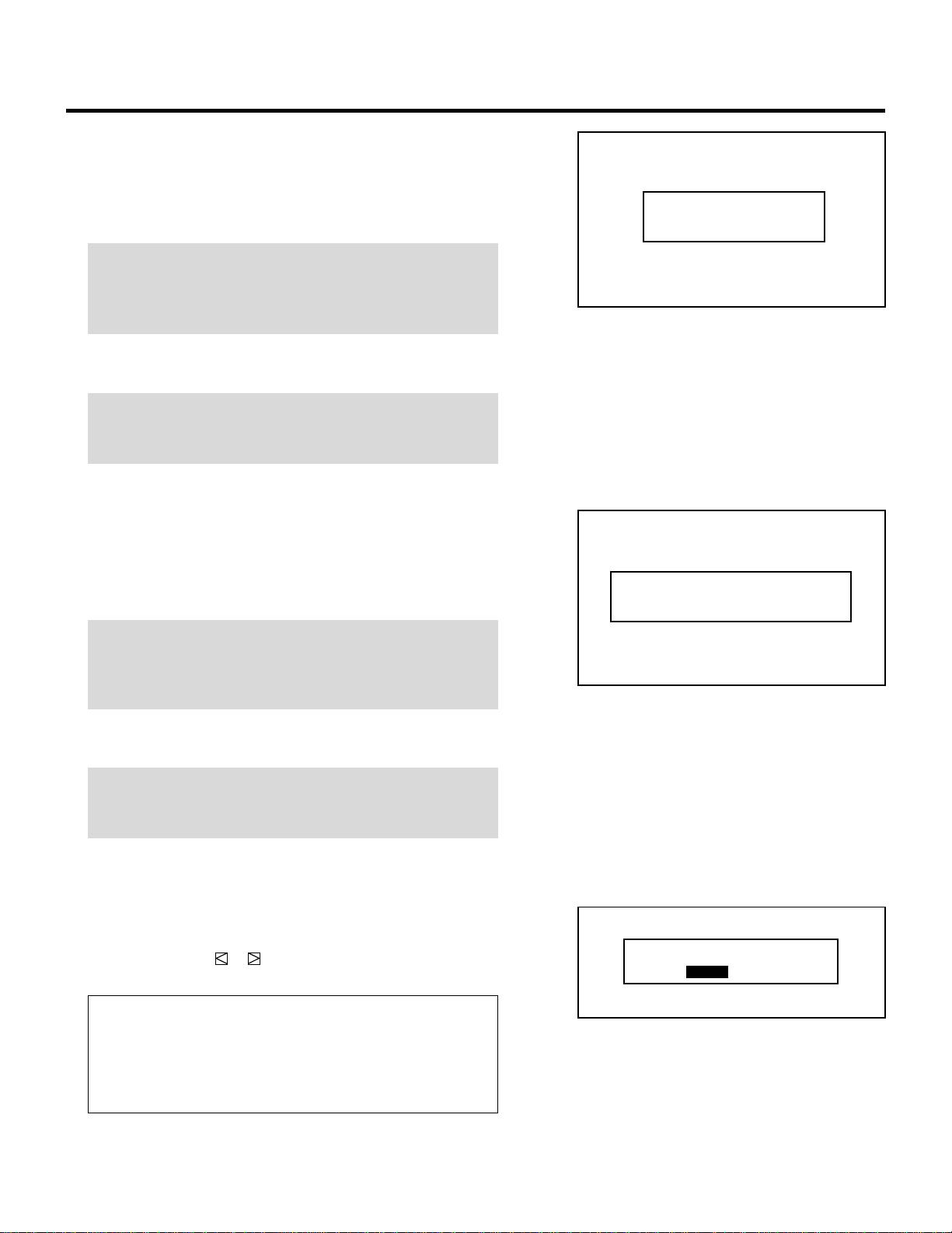
56
6 Enter a new passcode using the “1” through “0” buttons.
1) Each time you press the INPUT button, an asterisk will
appear under the “NEW PASSCODE?” message.
2) Once you have finished entering the four digit new passcode,
press ENTER.
NOTE: If you have made an error, press the NORMAL button to
delete the asterisk “∗”. Then re-enter the correct passcode. To
delete all the entered digits, hold down the CTL button then
press the NORMAL button.
3) If the passcode has been entered correctly, the “CONFIRM
NEW PASSCODE?” menu will be displayed.
NOTE: If the passcode is not entered correctly, the “WARNING
PASSCODE!!” message will be displayed. You are required to
enter the new passcode correctly.
7 Enter the new passcode again using the “1” through “0” buttons.
1) Each time you press the INPUT button, an asterisk will
appear under the “CONFIRM NEW PASSCODE?” message.
2) Once you have finished entering the four digit new passcode,
press ENTER.
NOTE: If you have made an error, press the NORMAL button to
delete the asterisk “∗”. Then re-enter the correct passcode. To
delete all the entered digits, hold down the CTL button then
press the NORMAL button.
3) If the entered passcode is correct, the “CHANGE
PASSCODE COMPLETE!!” message is displayed.
NOTE: If the passcode is not entered correctly, the “WARNING
DIFFERENT PASSCODE!!” message is displayed. You will be
required to enter the new passcode correctly.
8 To complete, press the END button.
• Whenever the END button is pressed, the “RETURN USER
MODE?” menu will be displayed.
Use the CURSOR or button to select either “YES” or
“NO” and press ENTER. This will exit the ADJUST mode.
Items to select
• YES ......... When you try to enter the ADJUST mode again,
you will need to re-enter your passcode.
• NO........... When you try to enter the ADJUST mode again,
you will not need to re-enter your passcode.
PASSCODE
RETURN USER MODE?
YES NO
––––
NEW PASSCODE?
––––
CONFIRM NEW PASSCODE?
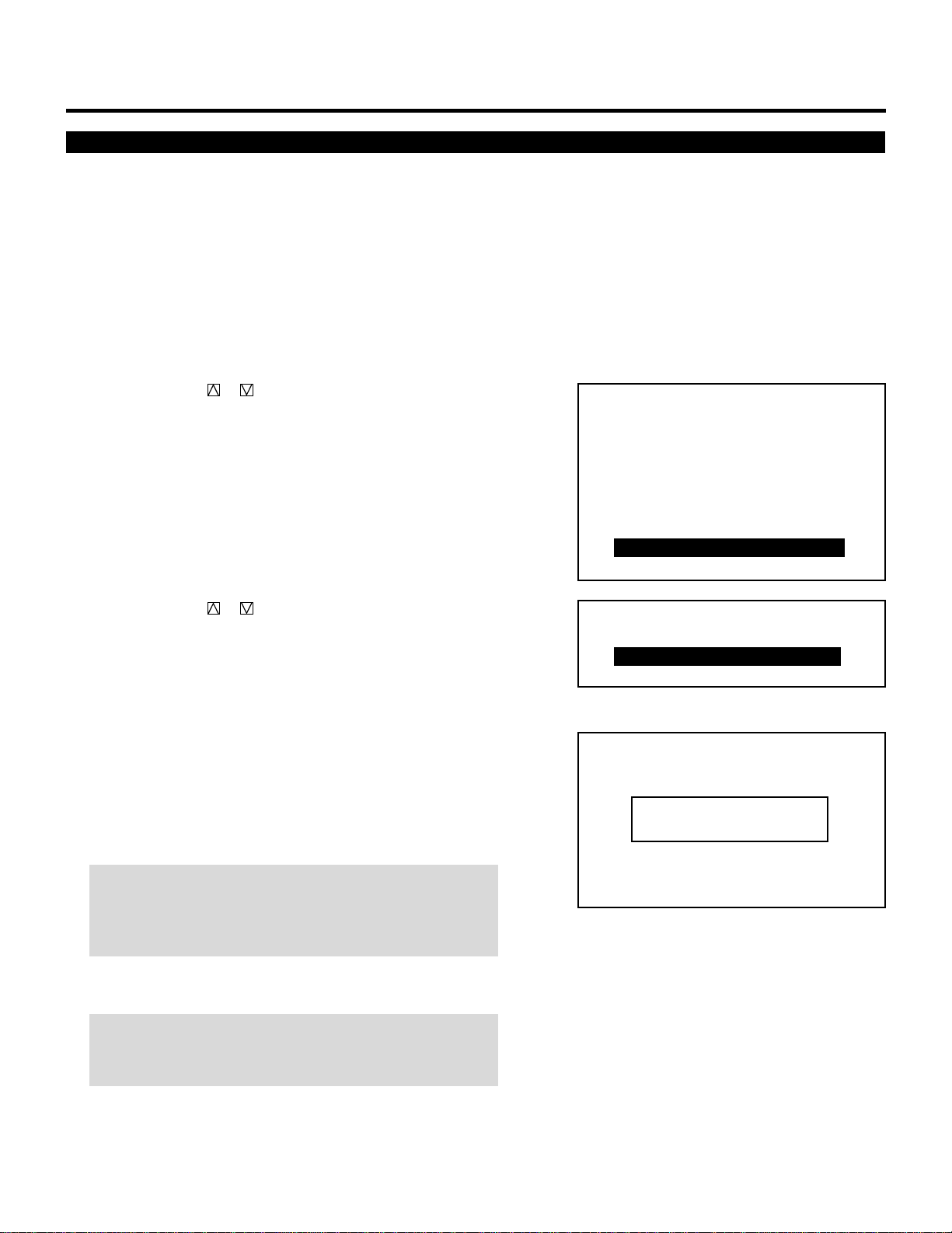
57
Canceling Your Passcode
PASSCODE
To cancel the passcode, proceed as follows:
1 Press the ADJUST button and then enter your passcode.
• The “PASSCODE?” screen will be displayed.
2 Enter the four digit current passcode using the “1” through “0”
buttons and then press ENTER.
• The “ADJUST” menu will be displayed.
3 Use the CURSOR or button to highlight “8/PASSCODE”.
Press the ENTER button to display the “PASSCODE” menu.
You can also select the “PASSCODE” menu directly by pressing
the INPUT “8” button.
• The seventh item is “7/PASSCODE” in stand alone adjust
menu.
4 Use the CURSOR or button to select “2/DISABLE”. Press
ENTER to display the “CURRENT PASSCODE?” menu. You
can also select the “CURRENT PASSCODE?” menu directly by
pressing the INPUT “2” button.
5 Enter the four digit passcode (the current passcode) using the “1”
through “0” buttons.
1) Each time you press the INPUT button, an asterisk will
appear under the “CURRENT PASSCODE?” message.
2) Once you have finished entering the four digit passcode, press
ENTER.
NOTE: If you have made an error, press the NORMAL button to
delete the asterisk “∗”. Then re-enter the correct passcode. To
delete all the entered digits, hold down the CTL button then
press the NORMAL button.
3) If the entered passcode is correct, the “PASSCODE DIS-
ABLE?” menu will be displayed.
NOTE: If the passcode is not correct, the “WARNING DIFFER-
ENT PASSCODE!!” message will be displayed. You will be
required to enter your correct passcode.
– ADJUST –
1 / SIGNAL ENTRY
2 / FOCUS
3 / ALIGNMENT
4 / CONVERGENCE
5 / WHITE BAL
6 / R,G,B GAIN
7 / HOUR METER
8 / PASSCODE
9 / OPTION
– PASSCODE –
1 / ENTRY
2 / DISABLE
CURRENT PASSCODE?
∗∗∗∗

58
6 Use the CURSOR or button to select either “YES” or “NO”
and then press ENTER.
Items to select
• YES ......... When selecting “YES”, the current passcode will
be canceled. You will not be required to re-enter
your passcode when you press the ADJUST button
to re-enter the ADJUST mode.
• NO........... When selecting “NO”, the current passcode will
remain in effect.
PASSCODE
PASSCODE DISABLE?
YES NO

29
123456
12345
6
12345
6
12345
6
12345
6
12345
6
SPECIFICATIONS.
Projection type ............ Refraction type
Projector and screen are separated
Projection system........3 lens and 3 CRTs in-line
Scanning frequency.....H 15 to 69 kHz/V 38 to 160Hz
(PG-6200/PG-6200G)
H 15 to 100 kHz/V 38 to 160Hz
(PG-9200/PG-9200G)
Retrace time ................ H 4.0 µS (fH 15 to 30kHz)
H 2.5 µS (fH 30 to 100kHz)
V 350 µS
Video bandwidth..........100MHz (-3dB) PG-9200/PG-9200G
80MHz (-3dB) PG-6200/PG-6200G
CRT .............................7 inch liquid cooled
Deflection angle 90 degrees
Lens ............................Hybrid lenses multilayer coating F1.0
Picture size ..................60 to 300 inches diagonal
Resolution ................... 1000TV lines
Pixel resolution............ 160021200 dots(PG-9200/PG-9200G)
128021024 dots (PG-6200/PG-6200G)
Light output.................1000 lumens
(Small area peak high light brightness)
Contrast ratio...............20 : 1 (HDTV method)
High voltage ................ 32kV
Input............................RGB signal 0.7Vp-p 75ohm positive (BNC)
H/V sync 0.7 to 4.0Vp-p 75 ohm/1 K ohm
negative or positive (BNC)
COMP sync 0.7 to 4.0Vp-p 75ohm/1 K ohm
negative or positive (BNC)
Sync on G 0.3 to 0.6Vp-p 75ohm negative (BNC)
Video 1.0Vp-p 75ohm positive (BNC) or
(switchable)
S-video: Y 1.0Vp-p 75ohm positive
C 0.28Vp-p 75ohm (burst level)
Video system NTSC, PAL, SECAM and
NTSC4.43
Convergence................Digital convergence (Pre-set 100 positions)
Quick copy convergence
Static and wave convergence
Point convergence: PG-6200/PG-6200G
Optional
PG-9200/PG-9200G Standard
Convergence limits ......Less than 0.2% of V-height
Warm up time..............20 minutes
Setup signal.................Cross hairs, Cross hatch, Dot, Window Pattern,
H test pattern
Power supply...............AC 120V 60Hz (PG-6200/PG-9200)
AC 220-240V 50Hz (PG-6200G/PG-9200G)
Power consumption .... PG-6200/PG-6200G 500W
PG-9200/PG-9200G 550W
Input current ...............6.8A (AC 120V) PG-6200
7.6A (AC 120V) PG-9200
4.0A (AC 220-240V) PG-6200G
4.4A (AC 220-240V) PG-9200G
Safety and regulation...PG-6200/PG-9200;
Meets FCC class A requirements
UL Approved (UL 1950, CSA 950)
DHHS Approved
Meets DOC (Canada)
Meets RED ACT
PG-6200G/PG-9200G;
Meets EMC Directive (EN55022,EN61000-3-
2, EN61000-3-3, EN55082-1, pr EN55024-
2, pr EN55024-3, pr EN55024-4)
Meets Low Voltage Directive (EN60950,
TÜV GS Approved)
PTB Approved
Cabinet dimensions .....610(W)2754(D)2309(H) mm
24 1/8(W)229 5/8(D)212 1/8(H) inch
Weight ......................... 56 kg/123.5 lbs
Remote control............ Wired application
Wireless (operating distance 7m/23ft.)
Remote control functions
.User remote (RG-6020); Power ON/OFF, Input
signal select, Picture mute, Bright, Contrast,
Color 1), Sharpness 1), Tint 2), Volume 3),
Sound mute 3), Source information, Static
convergence, Normalize, Enter, End
Full function remote (RC-6051); Test, Display,
Help, Information, Input list, Static focus, Edge
focus, H/V position, White balance select, Static
convergence, Wave convergence, Point
convergence, H/V amplitude, H/V linearity, H/V
key-stone, H/V pin-cushion, H/V blanking, Tilt,
Skew, H/V bow, Store, Normalize, Enter, End
Main control function ..Power ON/OFF, Input signal select, Picture
mute, Bright, Contrast, Color 1), Sharpness 1),
Tint 2), Volume 3), Sound mute 3), Source
information, Static convergence, Normalize,
Enter, End
External control ...........Power ON/OFF, Input signal select, Picture
mute, Remote control data input
PC control ................... Acceptable
Supplied accessories...Full function remote control unit (RC-6051),
User remote control unit (RC-6020), Remote
cable 4m/13ft., Remote cable 16m/52ft., AC
line cable, Operation manual, Set-Up manual*,
Installation manual*
Environment ................Temperature 0 to 40 degrees C
Humidity 0 to 90% non-condensing
Storage -10 to 50 degrees C
Sound emission...........PG-6200/PG-9200 45dB
PG-6200G/PG-9200G 70dB (A). Complies with
ISO 3744 or ISO 7779
1) This works only for VIDEO signals.
2) This works only for NTSC video signals.
3) This works only with the Switcher operation.
Specifications are subject to change without notice.
The dimensions given for the projector do not include
protruding parts.
*Set-Up manual and Installation manual are not included
with PG-9200G/PG-6200G.