Loading ...
Loading ...
Loading ...
6 JL AUDIO M 6 -10 I B
All specifications are subject to change without notice.
BEFORE YOU BEGIN INSTALLING
• Check with your local waterway authority for any regulations regarding the use
of accent/speaker lighting on your vessel.
• Turn off the audio system. It is also advisable to disconnect your battery system
whenever performing installation work.
• Before cutting, drilling or inserting any screw, check clearances on both sides of
the planned mounting surface. Also check for any potential obstacles, such as
wiring harnesses, fuel lines, hydraulic lines, etc. Check both sides of the vessel
before cutting any holes.
• If you are running cables through bulkheads, drill holes for the cable and use a
urethane or plastic grommet to protect the wire from chafing in the hole. Make
sure that the cables will clear any mechanical devices in the boat and secure
them with wire ties.
• Wear protective eyewear at all times and a dust mask and gloves when drilling
or cutting.
INSTALLATION PROCEDURE
Diagrams A & B (page 7) shows typical installation procedures into a fiberglass
panel, using the supplied hardware. Always follow proper safety procedures. Use
eye-protection at all times and a dust mask and gloves when cutting.
1) Choose a flat mounting surface that has sufficient depth and air space
behind it to accept the subwoofer.
2) Using a hole saw or jigsaw, cut a 8.875-inch (225 mm) diameter hole.
3) Route the speaker cable to the mounting location. For LED equipped
models, now is also a good time to run wires to the speaker location for
LED activation.
4) Place the woofer in the hole and mark the screw hole locations using a
sharp, pointed tool.
5) Remove the woofer and drill a pilot hole (see the Pilot Hole
Recommendations chart at the right) in each of the screw locations. It
is also advisable to use a hand-driven countersink tool on each hole to
further inhibit gel-coat cracking of fiberglass panels.
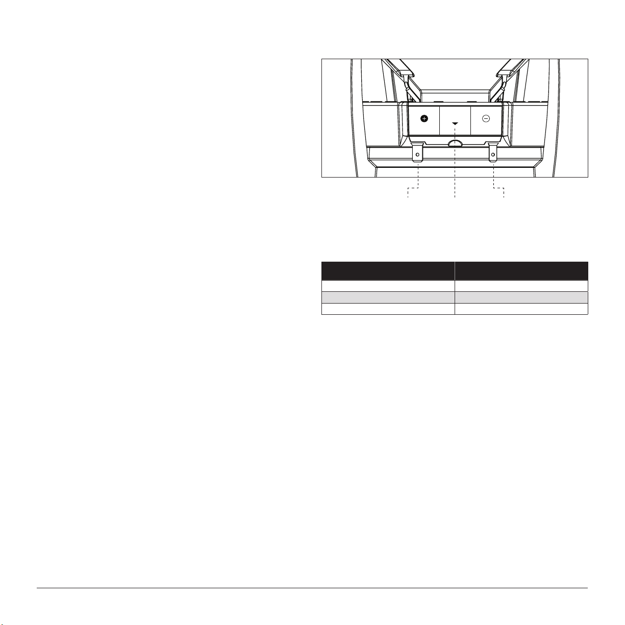
6) Connect the speaker wires from the amplifier to the woofer connections
(see Speaker Connections at right).
7) If equipped, connect the LED circuit leads (see page 5).
8) Place the woofer, with its grille in place, into the opening and while
holding the speaker firmly in its mounting location, evenly snug the
mounting screws in a criss-cross pattern, then hand tighten in a
criss-cross pattern.
Non-standard installations may require different hardware. Always use
marine-grade, stainless-steel fasteners to ensure a secure, reliable installation.
SPEAKER CONNECTIONS
SPEAKER SPEAKER
LIGHTING
from
amplier
negative
output
from
amplier
positive
output
from LED
activation wires
or RGB lighting
controller output
(LED models only)
Fiberglass Thickness Recommended Pilot Hole Drill Size
0.125 in. (3.18 mm) or less 1/8 in. (3.18 mm) pilot hole
foam core / fiberglass sandwich 1/8 in. (3.18 mm) pilot hole
larger than 0.125 in (3.18 mm) 9/64 in. (3.57 mm) pilot hole
#10 SCREW: PILOT HOLE RECOMMENDATIONS
Loading ...
Loading ...