EnglishFrançaisEspañol
DAIKIN ROOM AIR CONDITIONER
INSTALLATION MANUAL
R410A Split Series
Installation manual
Manuel dinstallation
Manual de instalación
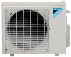
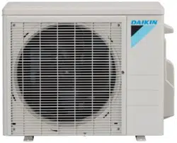
MODELS
FFQ09Q2VJU
FFQ12Q2VJU
FFQ15Q2VJU
FFQ18Q2VJU
Manuel dinstallation
1 ŶEnglish
Safety Considerations
Contents
Safety Considerations .................................... 1
Before Installation .......................................... 3
Accessories ..................................................... 3
Choosing an Installation Site ........................ 4
Indoor Unit Installation ................................... 6
1. Relation of ceiling opening to unit and
suspension bolt position .............................................. 6
2. Make the ceiling opening needed for installation
where applicable (For existing ceilings) ....................... 7
3. Installing the suspension bolts .................................... 7
4. Installing the indoor unit .............................................. 7
5. Drain piping work ......................................................... 8
6. Wiring .......................................................................... 11
Refrigerant Piping Work ................................. 14
1. Flaring the pipe end ..................................................... 14
2. Refrigerant piping ........................................................ 14
Installation of the Decoration Panel .............. 16
Field Settings .................................................. 16
1. Setting air outlet direction ............................................ 16
2. Setting for options ........................................................ 16
5GVVKPICKTƂNVGTUKIP ..................................................... 16
4. When implementing group control ............................... 17
5. 2 remote controllers (controlling 1 indoor unit
by 2 remote controllers) ............................................... 17
Trial Operation and Testing ............................ 17
1. Trial operation and testing ........................................... 17
2. Test items .................................................................... 19
3. How to diagnose for malfunction ................................. 20
Read these Safety Considerations for Installation carefully
before installing an air conditioner or heat pump. After
completing the installation, make sure that the unit operates
properly during the startup operation.
Instruct the user on how to operate and maintain the unit.
Inform users that they should store this installation manual
with the operation manual for future reference.
Always use a licensed installer or contractor to install this product.
Improper installation can result in water or refrigerant leakage,
GNGEVTKEUJQEMƂTGQTGZRNQUKQP
Meanings of DANGER, WARNING, CAUTION, and NOTE
Symbols:
DANGER
...........
Indicates an imminently hazardous
situation which, if not avoided, will
result in death or serious injury.
WARNING
.........
Indicates a potentially hazardous
situation which, if not avoided, could
result in death or serious injury.
CAUTION
..........
Indicates a potentially hazardous
situation which, if not avoided, may
result in minor or moderate injury.
It may also be used to alert against
unsafe practices.
NOTE
................
Indicates situations that may result
in equipment or property-damage
accidents only.
DANGER
r Refrigerant gas is heavier than air and replaces oxygen.
A massive leak can lead to oxygen depletion, especially
in basements, and an asphyxiation hazard could occur
leading to serious injury or death.
r
Do not ground units to water pipes, gas pipes, telephone
wires, or lightning rods as incomplete grounding can cause
a severe shock hazard resulting in severe injury or death.
Additionally, grounding to gas pipes could cause a gas leak
and potential explosion causing severe injury or death.
r If refrigerant gas leaks during installation, ventilate the
area immediately. Refrigerant gas may produce toxic gas
KHKVEQOGUKPVQEQPVCEVYKVJƂTG'ZRQUWTGVQVJKUICUEQWNF
cause severe injury or death.
r After completing the installation work, check that the
refrigerant gas does not leak throughout the system.
r &QPQVKPUVCNNWPKVKPCPCTGCYJGTGƃCOOCDNGOCVGTKCNU
are present due to risk of explosions that can cause
serious injury or death.
r Safely dispose all packing and transportation materials
in accordance with federal/state/local laws or ordinances.
Packing materials such as nails and other metal or
wood parts, including plastic packing materials used for
transportation may cause injuries or death by suffocation.
WARNING
r 1PN[SWCNKƂGFRGTUQPPGNOWUVECTT[QWVVJGKPUVCNNCVKQP
work. Installation must be done in accordance with this
installation manual. Improper installation may result in
YCVGTNGCMCIGGNGEVTKEUJQEMQTƂTG
r When installing the unit in a small room, take measures
to keep the refrigerant concentration from exceeding
CNNQYCDNGUCHGV[NKOKVU'ZEGUUKXGTGHTKIGTCPVNGCMUKPVJG
event of an accident in a closed ambient space, can lead
VQQZ[IGPFGƂEKGPE[
r 7UGQPN[URGEKƂGFCEEGUUQTKGUCPFRCTVUHQTKPUVCNNCVKQP
YQTM(CKNWTGVQWUGURGEKƂGFRCTVUOC[TGUWNVKPYCVGT
NGCMCIGGNGEVTKEUJQEMƂTGQTVJGWPKVHCNNKPI
r Install the air conditioner or heat pump on a foundation
strong enough that it can withstand the weight of the unit.
#HQWPFCVKQPQHKPUWHƂEKGPVUVTGPIVJOC[TGUWNVKPVJGWPKV
falling and causing injuries.
r Take into account strong winds, typhoons, or earthquakes
when installing. Improper installation may result in the unit
falling and causing accidents.
2ŶEnglish
r Make sure that a separate power supply circuit is provided
for this unit and that all electrical work is carried out by
SWCNKƂGFRGTUQPPGNCEEQTFKPIVQNQECNUVCVGCPFPCVKQPCN
TGIWNCVKQPU#PKPUWHƂEKGPVRQYGTUWRRN[ECRCEKV[QT
improper electrical construction may lead to electric shock
QTƂTG
r /CMGUWTGVJCVCNNYKTKPIKUUGEWTGFVJCVURGEKƂGFYKTGU
are used, and that no external forces act on the terminal
connections or wires. Improper connections or installation
OC[TGUWNVKPƂTG
r When wiring, position the wires so that the electrical
wiring box cover can be securely fastened. Improper
positioning of the electrical wiring box cover may result in
GNGEVTKEUJQEMƂTGQTVJGVGTOKPCNUQXGTJGCVKPI
r Before touching electrical parts, turn off the unit.
r The circuit must be protected with safety devices in
accordance with local and national codes, i.e. a fuse, a
circuit breaker, a disconnect or a GFCI.
r
Securely fasten the outdoor unit terminal cover (panel). If the
terminal cover/panel is not installed properly, dust or water
OC[GPVGTVJGQWVFQQTWPKVECWUKPIƂTGQTGNGEVTKEUJQEM
r
When installing or relocating the system, keep the refrigerant
EKTEWKVHTGGHTQOUWDUVCPEGUQVJGTVJCPVJGURGEKƂGF
refrigerant (R410A) such as air. Any presence of air or other
foreign substance in the refrigerant circuit can cause an
abnormal pressure rise or rupture, resulting in injury.
r Do not change the setting of the protection devices. If the
pressure switch, thermal switch, or other protection device
is shorted and operated forcibly, or parts other than those
URGEKƂGFD[&CKMKPCTGWUGFƂTGQTGZRNQUKQPOC[QEEWT
CAUTION
r &QPQVVQWEJVJGUYKVEJYKVJYGVƂPIGTU6QWEJKPICUYKVEJ
YKVJYGVƂPIGTUECPECWUGGNGEVTKEUJQEM
r Do not allow children to play on or around the unit to
prevent injury.
r 6JGJGCVGZEJCPIGTƂPUCTGUJCTRGPQWIJVQEWV6QCXQKF
KPLWT[YGCTINQXGUQTEQXGTVJGƂPUYJKNGYQTMKPICTQWPF
them.
r Do not touch the refrigerant pipes during and immediately
after operation as the refrigerant pipes may be hot or
EQNFFGRGPFKPIQPVJGEQPFKVKQPQHVJGTGHTKIGTCPVƃQYKPI
through the refrigerant piping, compressor, and other
refrigerant cycle parts. Your hands may suffer burns or
frostbite if you touch the refrigerant pipes. To avoid injury,
give the pipes time to return to normal temperature or, if
you must touch them, be sure to wear proper gloves.
r Install drain piping to proper drainage. Improper drain
piping may result in water leakage and property damage.
r Insulate piping to prevent condensation.
r Be careful when transporting the product.
r Do not turn off the power immediately after stopping
operation. Always wait for at least 5 minutes before turning
off the power. Otherwise, water leakage may occur.
r Do not use a charging cylinder. Using a charging cylinder
may cause the refrigerant to deteriorate.
r Refrigerant R410A in the system must be kept clean, dry,
and tight.
(a) Clean and Dry -- Foreign materials (including mineral
oils such as SUNISO oil or moisture) should be
prevented from getting into the system.
(b)
Tight -- R410A does not contain any chlorine, does not
destroy the ozone layer, and does not reduce the earth’s
protection again harmful ultraviolet radiation. R410A
can contribute to the greenhouse effect if it is released.
Therefore take proper measures to check for the tightness
of the refrigerant piping installation. Read the chapter
Refrigerant Piping Work and follow the procedures.
r Since R410A is a blend, the required additional refrigerant
must be charged in its liquid state. If the refrigerant is
charged in a state of gas, its composition can change and
the system will not work properly.
r The indoor unit is for R410A. See the catalog for indoor
models that can be connected. Normal operation is not
possible when connected to other units.
r
Remote controller (wireless kit) transmitting distance can be
UJQTVGTVJCPGZRGEVGFKPTQQOUYKVJGNGEVTQPKEƃWQTGUEGPV
lamps (inverter or rapid start types). Install the indoor unit
HCTCYC[HTQOƃWQTGUEGPVNCORUCUOWEJCURQUUKDNG
r
Indoor units are for indoor installation only. Outdoor units can be
installed either outdoors or indoors. This unit is for indoor use.
r Do not install the air conditioner or heat pump in the
following locations:
(a) Where a mineral oil mist or oil spray or vapor is
produced, for example, in a kitchen.
Plastic parts may deteriorate and fall off or result in
water leakage.
(b) Where corrosive gas, such as sulfurous acid gas, is
produced.
Corroding copper pipes or soldered parts may result in
refrigerant leakage.
(c) Near machinery emitting electromagnetic waves.
'NGEVTQOCIPGVKEYCXGUOC[FKUVWTDVJGQRGTCVKQPQH
the control system and cause the unit to malfunction.
(d)
9JGTGƃCOOCDNGICUOC[NGCMYJGTGVJGTGKUECTDQP
ƂDGTQTKIPKVCDNGFWUVUWURGPUKQPKPVJGCKTQTYJGTG
XQNCVKNGƃCOOCDNGUUWEJCUVJKPPGTQTICUQNKPGCTGJCPFNGF
1RGTCVKPIVJGWPKVKPUWEJEQPFKVKQPUECPECWUGCƂTG
r
Take adequate measures to prevent the outdoor unit from being
used as a shelter by small animals. Small animals making
contact with electrical parts can cause malfunctions, smoke, or
ƂTG+PUVTWEVVJGWUGTVQMGGRVJGCTGCCTQWPFVJGWPKVENGCP
NOTE
r The indoor unit should be positioned where the unit and
inter-unit wires (outdoor to indoor) are at least 3.3ft (1m)
away from any televisions or radios. (The unit may cause
interference with the picture or sound.) Depending on the
TCFKQYCXGUCFKUVCPEGQHHVOOC[PQVDGUWHƂEKGPV
to eliminate the noise.
r Dismantling the unit, treatment of the refrigerant, oil and
additional parts must be done in accordance with the
relevant local, state, and national regulations.
r
Do not use the following tools that are used with
conventional refrigerants: gauge manifold, charge hose, gas
NGCMFGVGEVQTTGXGTUGƃQYEJGEMXCNXGTGHTKIGTCPVEJCTIG
base, vacuum gauge, or refrigerant recovery equipment.
r If the conventional refrigerant and refrigerator oil are
mixed in R410A, the refrigerant may deteriorate.
r This air conditioner or heat pump is an appliance that
should not be accessible to the general public.
r #UFGUKIPRTGUUWTGKURUKVJGYCNNVJKEMPGUUQHƂGNF
installed pipes should be selected in accordance with the
relevant local, state, and national regulations.
FTN001-U
English
3 ŶEnglish
Before Installation
r Leave the unit inside its packaging until you reach the installation site. Where unpacking is unavoidable, use a sling of soft
material or protective plates together with a rope when lifting, this to avoid damage or scratches to the unit.
When unpacking the unit or when moving the unit after unpacking, be sure to lift the unit by holding on to the hanger bracket
without exerting any pressure on other parts, especially on refrigerant piping, drain piping and other resin parts.
r Refer to the installation manual of the outdoor unit for items not described in this manual.
r Caution concerning refrigerant series R410A:
The connectable outdoor units must be designed exclusively for R410A.
Precautions
r Do not install or operate the unit in places mentioned below.
2NCEGUYKVJOKPGTCNQKNQTƂNNGFYKVJQKNXCRQTQTURTC[NKMGKPMKVEJGPU2NCUVKERCTVUOC[FGVGTKQTCVG
- Where corrosive gas like sulphurous gas exists. (Copper tubing and brazed spots may corrode.)
9JGTGXQNCVKNGƃCOOCDNGICUNKMGVJKPPGTQTICUQNKPGKUWUGF
- Where machines generating electromagnetic waves exist. (Control system may malfunction.)
9JGTGVJGCKTEQPVCKPUJKIJNGXGNUQHUCNVUWEJCUPGCTVJGQEGCPCPFYJGTGXQNVCIGƃWEVWCVGUCNQVGIKPHCEVQTKGU#NUQ
inside vehicles or vessels.
r When selecting the installation site, use the supplied template for installation.
r Do not install accessories on the casing directly. Drilling holes in the casing may damage electrical wires and consequently cause
ƂTG
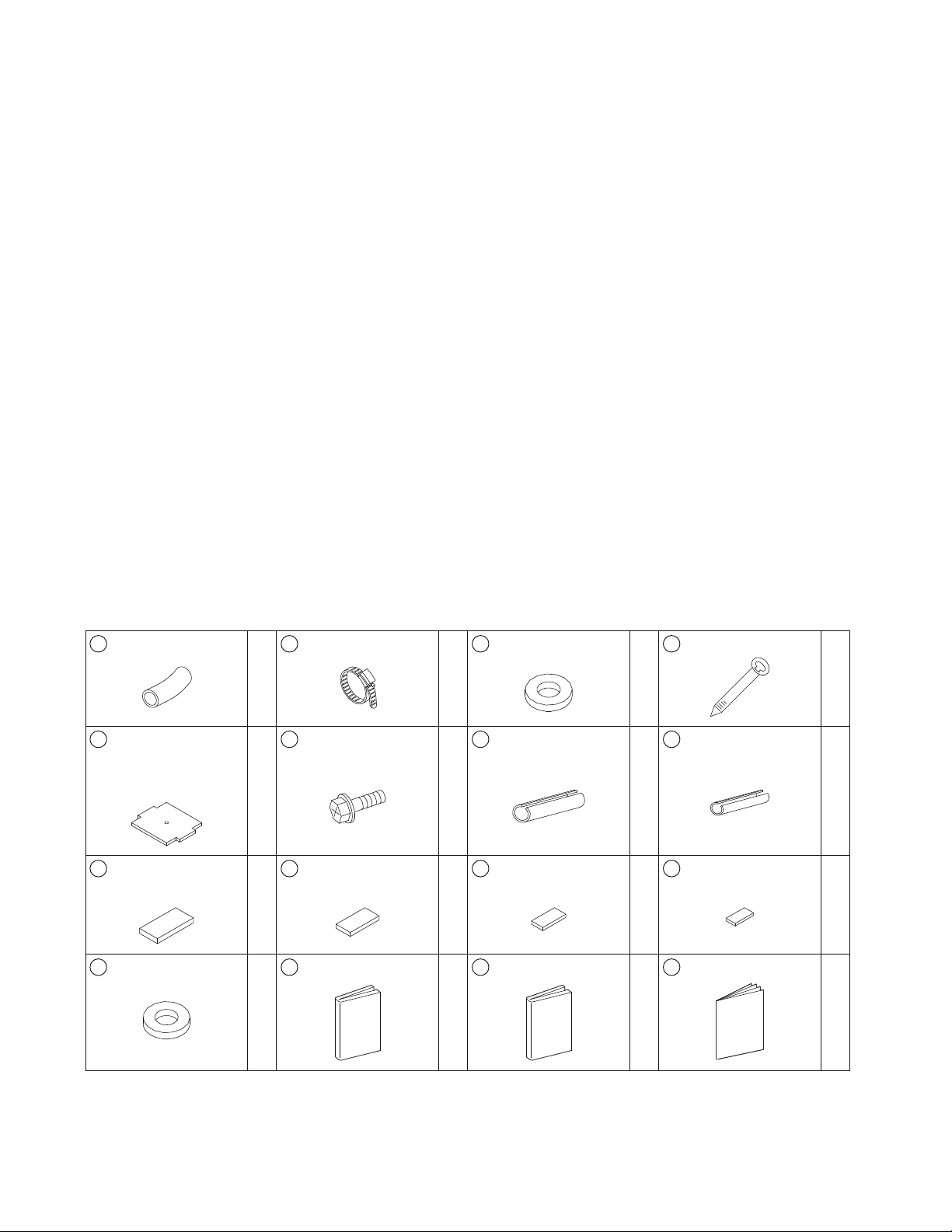
Accessories
A
Drain hose
1
B
Clamp metal
1
C
Washer for hanger
bracket
8
D
Clamp
7
'
Template
(cut out from upper
part of packing)
1
F
Screws (M5)
(for template)
4
G
Fitting insulation
(for gas pipe)
1
H
Fitting insulation
(for liquid pipe)
1
J
Sealing pad (large)
1
K
Sealing pad
(medium A)
1
L
Sealing pad
(medium B)
1
M
Sealing pad (small)
1
N
Washer for conduit
1
P
Operation manual
1
Q
Installation manual
1
R
Warranty
1

4ŶEnglish
Optional Accessories
r The optional decoration panel and remote controller are required for this indoor unit.
Table 1
Optional decoration panel
Type A BYFQ60B3W1 Color: White
Type B BYFQ60C2W1W Color: White
Type B BYFQ60C2W1S Color: Silver
r There are 2 types of remote controllers: wired and wireless. Select a remote controller from Table 2 according to customer
request and install in an appropriate place.
Table 2
Remote controller type Heat Pump type
Wired type $4%'
Wireless type BRC082A41W / BRC082A42W / BRC082A42S
r If you wish to use a remote controller that is not listed in Table 2, select a suitable remote controller after consulting catalogs and
technical materials.
Choosing an Installation Site
Hold the unit by the 4 hanger brackets when opening the box and moving it, and do not exert pressure on to any other part, piping
(refrigerant, drain, etc.), or plastic parts.
If the temperature or humidity inside the ceiling might rise above 86°F (30°C) or RH 80%, respectively, add extra insulation to the
unit.
7UGRQN[GVJ[NGPGHQCOCUKPUWNCVKQPCPFOCMGUWTGKVKUCVNGCUVKPEJOOVJKEMCPFƂVUKPUKFGVJGEGKNKPIQRGPKPI
5GNGEVVJGCKTƃQYFKTGEVKQPUDGUVUWKVGFVQVJGTQQOCPFRQKPVQHKPUVCNNCVKQP
(QTCKTFKUEJCTIGKPFKTGEVKQPUKVKUPGEGUUCT[VQOCMGƂGNFUGVVKPIUD[OGCPUQHVJGTGOQVGEQPVTQNNGTCPFVQENQUGVJG
air outlet (s).
4GHGTVQVJGKPUVCNNCVKQPOCPWCNQHVJGDNQEMKPIRCFMKVUQNFUGRCTCVGN[CPFVQp(KGNF5GVVKPIUqQPRCIG
r Before choosing the installation site, obtain user approval.
The indoor unit should be positioned in a place where:
1) both the air inlet and air outlet are unobstructed,
2) the unit is not exposed to direct sunlight,
3) the unit is away from the source of heat or steam,
4) there is no source of machine oil vapor (this may shorten the indoor unit service life),
5) cool/warm air is circulated throughout the room,
6) VJGWPKVKUCYC[HTQOGNGEVTQPKEKIPKVKQPV[RGƃWQTGUEGPVNCORUKPXGTVGTQTTCRKFUVCTVV[RGCUVJG[OC[CHHGEVVJGTGOQVG
controller range,
7) no laundry equipment is nearby,
8) drainage can be performed without any problem,
9) the weight of the indoor unit can be adequately supported,
10) VJGYCNNKUPQVUKIPKƂECPVN[VKNVGF
11) room can be left for installation and service work,
12) VJGTGKUPQTKUMQHƃCOOCDNGICUNGCMKPI
13) VJGTGSWKTGFNGPIVJQHKPFQQTQWVFQQTRKRKPIYQWNFPQVGZEGGFVJGURGEKƂGFOCZKOWONGPIVJUGGVJGKPUVCNNCVKQPOCPWCNVJCV
came with the outdoor unit for details).
English
5 ŶEnglish
Choosing an Installation Site
+PUVCNNCVKQP5RCEG4GSWKTGOGPVU
ű60
(1500)
ű11-3/4
(300)
ű98 (2500)
*
ű60
(1500)
*
ű60
(1500)
For installation
in high places
Air
outlet
Air
outlet
Air
inlet
*
ű60 (1500)
*
ű60 (1500)
unit:inch (mm)
*
ű60
(1500)
*
ű60
(1500)
r Leave 8 inch (200mm) or more space where marked with the
*
, on sides where the air outlet is closed.
#KTƃQYFKTGEVKQP
r The air direction shown is an example.
r Select the appropriate number of directions according to the shape of the room and the location of the unit. (Field settings have to
be made using the remote controller and the outlet vents have to be shut off if 2 or 3 directions are selected.
See the blocking pad kit (sold separately) installation manual for details.)
#KTƃQYFKTGEVKQP'ZCORNG
Piping
Air outlet
Piping Piping
Air outlet in 2 directions Air outlet in 3 directions Air outlet in 4 directions
7UGUWURGPUKQPDQNVUHQTKPUVCNNCVKQP%JGEMYJGVJGTVJGEGKNKPIKUUVTQPIGPQWIJVQUWRRQTVVJG
YGKIJVQHVJGWPKVQTPQV+HVJGTGKUCTKUMTGKPHQTEGVJGEGKNKPIDGHQTGKPUVCNNKPIVJGWPKV
(Installation pitch is marked on the template. Refer to it to check for points requiring reinforcing.)
6ŶEnglish
Indoor Unit Installation
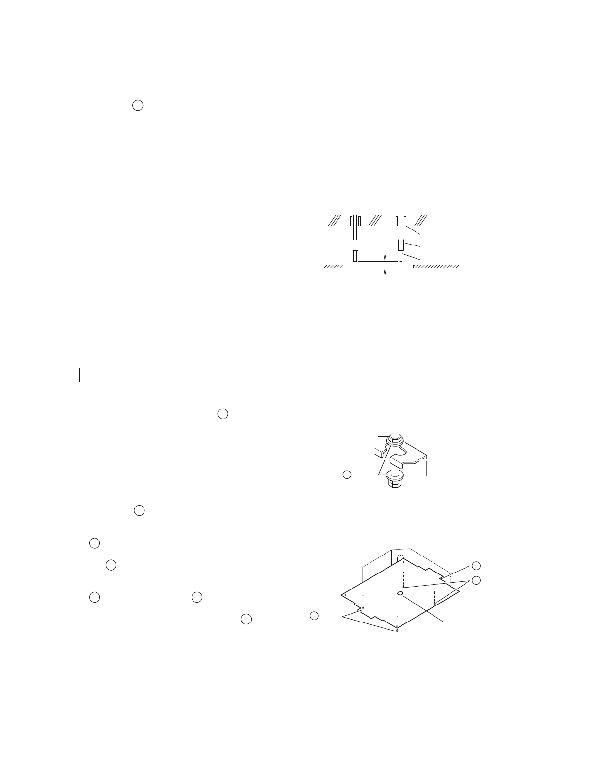
1. 4GNCVKQPQHEGKNKPIQRGPKPIVQWPKVCPFUWURGPUKQPDQNVRQUKVKQP
Top view
Side view
Refrigerant
piping
Suspension
bolt (×4)
False ceiling
7-1/16
(180)
ű
*
13/16
(20)
ű
*
13/16
(20)
2-1/2
(63)
27-9/16 (700)
Decoration panel
22-5/8 (575)
Indoor unit
21 (533)
Suspension bolt pitch
23-1/16-26 (585-660)
Ceiling opening
23-1/16-26 (585-660)
Ceiling opening
27-9/16 (700)
Decoration panel
23-1/16-26 (585-660)
Ceiling opening
22-5/8 (575)
Indoor unit
21 (533)
Suspension bolt pitch
Hanger
bracket
Refrigerant
piping
Suspension
bolt (×4)
24-7/16 (620)
Decoration panel
7-1/2
(190)
23-1/16-23-7/16 (585-595)
Ceiling opening
22-5/8 (575)
Indoor unit
24-7/16 (620)
Decoration panel
23-1/16-23-7/16 (585-595)
Ceiling opening
ű
*
1/2
(12.5)
ű
*
1/2
(12.5)
22-5/8 (575)
Indoor unit
2-1/2
(63)
21 (533)
Suspension bolt pitch
False ceiling
23-1/16-23-7/16 (585-595)
Ceiling opening
21 (533)
Suspension bolt pitch
Top view
Side view
unit: inch (mm)
For decoration panel type B
For decoration panel type A
Hanger
bracket
11-3/4
(298)
11-1/4
(285)
NOTE
r *If the panel does not extend over the ceiling by this amount, supplement with extra ceiling material or restore the ceiling.
r Install the inspection opening on the electrical wiring box side where maintenance and
inspection of the electrical wiring box and drain pump are easy.
Inspection
opening
Electrical wiring box
11-3/4
(300)
17-11/16×17-11/16
(450×450)
English
7 ŶEnglish
Indoor Unit Installation
2. /CMGVJGEGKNKPIQRGPKPIPGGFGFHQTKPUVCNNCVKQPYJGTGCRRNKECDNG
(For existing ceilings)
r Refer to the
'
template for ceiling opening dimensions.
r Create the ceiling opening required for installation. From the side of the opening to the casing outlet, implement the
refrigerant and drain piping and wiring for remote controller (unnecessary for wireless type) and wiring between units.
Refer to each Drain piping work or Wiring section.
r After making an opening in the ceiling, it may be necessary to reinforce ceiling beams to keep the ceiling level and to
prevent it from vibrating. Consult the builder for details.
3. +PUVCNNKPIVJGUWURGPUKQPDQNVU
(Use either a M8-M10 size bolt or the equivalent)
Use a hole-in anchor for existing ceilings, and a sunken
KPUGTVUWPMGPCPEJQTQTQVJGTƂGNFUWRRNKGFRCTVUHQTPGY
ceilings to reinforce the ceiling to bear the weight of the unit.
Adjust clearance (2-4 inch (50-100mm)) from the ceiling
before proceeding further.
r #NNVJGCDQXGRCTVUCTGƂGNFUWRRNKGF
2-4
(50-100)
unit:inch (mm)
Anchor
Ceiling slab
Installation Example
Long nut or turn-buckle
Suspension bolt
False ceiling
4. Installing the indoor unit
9JGPKPUVCNNKPIQRVKQPCNCEEGUUQTKGUGZEGRVHQTVJGFGEQTCVKQPRCPGNTGCFCNUQVJGKPUVCNNCVKQPOCPWCNQHVJG
QRVKQPCNCEEGUUQTKGU&GRGPFKPIQPVJGƂGNFEQPFKVKQPUKVOC[DGGCUKGTVQKPUVCNNQRVKQPCNCEEGUUQTKGUDGHQTGVJG
KPFQQTWPKVKUKPUVCNNGF*QYGXGTHQTGZKUVKPIEGKNKPIUCNYC[UKPUVCNNHTGUJCKTKPVCMGMKVDGHQTGKPUVCNNKPIVJGWPKV
#UHQTVJGRCTVUVQDGWUGFHQTKPUVCNNCVKQPYQTMDGUWTGVQWUGVJGRTQXKFGFCEEGUUQTKGUCPFURGEKƂGFRCTVUFGUKIPCVGFD[
Daikin.
(QTPGYEGKNKPIU
1) Install the indoor unit temporarily.
r Attach the hanger bracket to the suspension bolt. Be sure
VQƂZKVUGEWTGN[D[WUKPICPWVCPF
C
washer from the
upper and lower sides of the hanger bracket.
Hanger bracket
Double nut
ƂGNFUWRRN[VKIJVGP
Nut
ƂGNFUWRRN[
9CUJGT
C
Securing the hanger bracket
2) Refer to the
'
template for ceiling opening dimension.
Consult the builder or carpenter for details.
r The center of the ceiling opening is indicated on the
'
template. This indication also indicates the center of the
unit.
r The
'
template can be rotated by 90° to be able to
indicate the correct dimensions on all 4 sides.
r After cutting the template from the packaging, attach the
'
template to the unit with
F
screws (×4) as shown in
ƂIWTG
r Ceiling height is shown on the side of the
'
template.
Adjust the height of the unit according to this indication.
Installation of template
Template
E
Screws
F
ScrewsF
Center of the ceiling opening
%GKNKPIYQTM
3) Adjust the unit to the right position for installation.
(Refer to 4GNCVKQPQHEGKNKPIQRGPKPIVQWPKVCPFUWURGPUKQPDQNVRQUKVKQP.)

8ŶEnglish
CAUTION
+HVJGWPKVKUVKNVGFCICKPUVEQPFGPUCVGƃQYVJGƃQCVUYKVEJOC[OCNHWPEVKQPCPFECWUGYCVGTVQFTKR
4) Check the unit is horizontally level.
r The indoor unit is equipped with a built-in drain pump
CPFƃQCVUYKVEJ8GTKH[VJCVKVKUNGXGND[WUKPICYCVGT
NGXGNQTCYCVGTƂNNGFXKP[NVWDG
5) Remove the
'
template.
Water level
Vinyl tube
Vinyl tube
Maintaining horizontality
For existing ceilings
1) Install the indoor unit temporarily.
r Attach the hanger bracket to the suspension bolt. Be sure
to fix it securely by using a nut and
C
washer from the
upper and lower sides of hanger bracket.
Hanger bracket
Double nut
ƂGNFUWRRN[VKIJVGP
Nut
ƂGNFUWRRN[
9CUJGT
C
Securing the hanger bracket
2) Adjust the height and position of the unit.
(Refer to 4GNCVKQPQHEGKNKPIQRGPKPIVQWPKVCPFUWURGPUKQPDQNVRQUKVKQP.)
3) Perform steps 4) in
(QTPGYEGKNKPIU
.
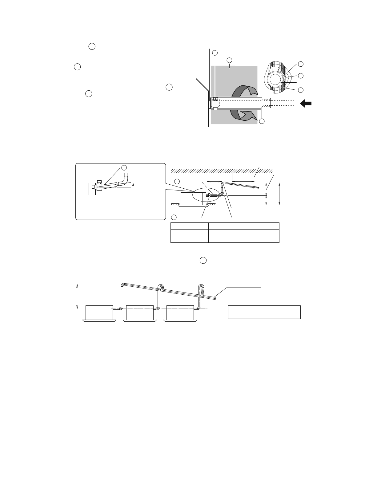
5. &TCKPRKRKPIYQTM
CAUTION
r Water pooling in the drainage piping can cause the drain to clog.
r &QPQVEQPPGEVVJGFTCKPRKRKPIFKTGEVN[VQUGYCIGRKRGUVJCVUOGNNQHCOOQPKC6JGCOOQPKCKPVJGUGYCIGOKIJV
enter the indoor unit through the drain pipes and corrode the heat exchanger.
r -GGRKPOKPFVJCVVJGFTCKPRKRGDGEQOGUDNQEMGFKHYCVGTEQNNGEVUQPKV
1. Install of drain piping
r +PUVCNNVJGFTCKPRKRKPICUUJQYPKPVJGƂIWTGCPFVCMGOGCUWTGUCICKPUVEQPFGPUCVKQP+ORTQRGTN[TKIIGFRKRKPIEQWNF
lead to leaks and eventually wet furniture and belongings.
r Keep piping as short as possible and slope it downwards at a gradient of at least 1/100 so that air may not remain
trapped inside the pipe.
r Keep pipe size equal to or greater than that of the connecting pipe (vinyl pipe of nominal diameter 13/16 inch (20mm)
and outer diameter 1 inch (26mm)).
r Push the supplied drain hose as far as possible over the drain socket.
r +HVJGFTCKPJQUGECPPQVDGUWHƂEKGPVN[UGVQPCUNQRGTGHGTVQp2TGECWVKQPUHQTFTCKPTCKUKPIRKRKPIq.
r To keep the drain hose from sagging, space hanger bracket every 40-60 inch (1000-1500mm).
1/100
gradient or more
Hanger bracket
GOOD
40-60 inch
(1000-1500mm)
WRONG WRONG
English
9 ŶEnglish
Indoor Unit Installation
r Tighten the
B
clamp metal as indicated in the
illustration.
r #HVGTVJGVGUVKPIQHFTCKPRKRKPIKUƂPKUJGFCVVCEJVJG
drain
J
sealing pad (large) supplied with the unit
over the uncovered part of the drain socket (= between
drain hose and unit body).
r Wrap the supplied large sealing pad over the
B
clamp
metal and
A
FTCKPJQUGVQKPUWNCVGCPFƂZKVYKVJ
clamps.
r Insulate the complete drain piping inside the building
ƂGNFUWRRN[
r +HVJGFTCKPJQUGECPPQVDGUWHƂEKGPVN[UGVQPCUNQRG
ƂVVJGJQUGYKVJFTCKPTCKUKPIRKRKPIƂGNFUWRRN[
Clamp metalB
Clamp metalB
Sealing pad
(large)
J
Sealing pad (large)J
Drain socket
Drain socket
&TCKPRKRKPIƂGNFUWRRN[
Drain hoseA
Drain hoseA
View A
A
Precautions for drain raising piping
r Install the drain raising pipes at a height of less than H2.
r Install the drain raising pipes at a right angle to the indoor unit and no more than 11-3/4 inch (300mm) from the unit.
Adjustable
Ceiling slab
Ű11-3/4
(300)
40-60
(1000-1500)
unit: inch (mm)
Hanger bracket
33-7/16
(850)
H2H1
Level or tilted
slightly up
To prevent air bubbles in the drain hose, keep
it level or slightly tilted up. Any bubbles in the
hose might cause the unit to make noise due
VQDCEMƃQYYJGPVJGFTCKPRWORUVQRU
Clamp metalB
Drain hoseA
Drain hoseA
Drain raising pipe
Raising section
Decoration panel H1 H2
Type A 8-1/16 (205) Ű25-3/8 (645)
Type B 8-11/16 (220) Ű24-13/16 (630)
r To ensure no excessive pressure is applied to the included
A
drain hose, do not bend or twist the hose when
installing as it could cause leakage.
r If converging multiple drain pipes, install according to the procedure shown below.
Central drain pipe
0–25-3/8 inch
(0-645mm)
The drain pipe should have a downward
slope of at least 1/100 to prevent air
pockets from forming.
Water accumulating in the drain piping
can cause the drain to clog.
Select converging drain pipes with gauges is suitable for the operating capacity of the unit.
10ŶEnglish
#HVGTRKRKPIYQTMKUƂPKUJGFEJGEMKHFTCKPCIGƃQYUUOQQVJN[
r #FFCRRTQZKOCVGN[ICNQHYCVGTUNQYN[HTQOVJGCKTQWVNGVCPFEJGEMFTCKPCIGƃQY
unit: inch (mm)
Method of adding water
Drain pipe
Drain socket
YCVGTƃQYXKGYRQKPV
Drain pump location
Plastic container for pouring
Tube should be about 4 inch
(100mm) long.
5GTXKEGFTCKPQWVNGV
(with rubber plug)
Use this outlet to
drain water from
the drain pan.
ű
(100)
9JGPGNGEVTKEYKTKPIYQTMKUƂPKUJGF
r %JGEMFTCKPCIGƃQYFWTKPI%11.QRGTCVKQPGZRNCKPGFKPp6TKCNQRGTCVKQPCPFVGUVKPIq on page 17.
9JGPGNGEVTKEYKTKPIYQTMKUPQVƂPKUJGF
CAUTION
'NGEVTKECNYKTKPIYQTMUJQWNFDGFQPGD[CEGTVKƂGFGNGEVTKEKCP
r +HUQOGQPGYJQFQGUPQVJCXGVJGRTQRGTSWCNKƂECVKQPURGTHQTOUVJGYQTMRGTHQTOVJGHQNNQYKPICEVKQPUCHVGTVJGVTKCN
operation is complete.
1) 4GOQXGVJGGNGEVTKECNYKTKPIDQZEQXGTUETGYU%QPPGEVVJGUKPINGRJCUGRQYGTUWRRN[5+0).'2*#5'|*\
8VQEQPPGEVKQPU0QCPF0QQPVJGVGTOKPCNDNQEMHQTRQYGTUWRRN[
Do not connect to No.3 of the terminal block for power supply or the drain pump will not operate.
When carrying out wiring work around the electrical wiring box, make sure none of the connectors come undone.
Be sure to attach the electrical wiring box cover before turning on the power.
2) #HVGTEQPƂTOKPIFTCKPCIGVWTPQHHVJGRQYGTUWRRN[CPFTGOQXGVJGRQYGTUWRRN[YKTKPI
3) Attach the electrical wiring box cover as before.
Screws
Electrical wiring box cover
Ground
Terminal block for power supply
Single phase power supply
(60Hz 208/230V)
No.2
No.1
English
11 ŶEnglish
Indoor Unit Installation
6. Wiring
4GHGTCNUQVQVJGKPUVCNNCVKQPOCPWCNHQTVJGQWVFQQTWPKV
WARNING
r &QPQVWUGVCRRGFYKTGUGZVGPUKQPEQTFUQTUVCTDWTUVEQPPGEVKQPUCUVJG[OC[ECWUGQXGTJGCVKPIGNGEVTKEUJQEMQTƂTG
r Do not use locally purchased electrical parts inside the product. (Do not branch the power for the drain pump, etc., from the
VGTOKPCNDNQEM&QKPIUQOC[ECWUGGNGEVTKEUJQEMQTƂTG
r &QPQVEQPPGEVVJGRQYGTYKTGVQVJGKPFQQTWPKV&QKPIUQOC[ECWUGGNGEVTKEUJQEMQTƂTG
CAUTION
r When connecting the connection wire to the terminal block using a single core
wire, be sure to perform curling.
2TQDNGOUYKVJVJGKPUVCNNCVKQPOC[ECWUGJGCVCPFƂTGU
Good Wrong
r When clamping wiring, use the included clamping material to prevent outside pressure being exerted on the wiring
EQPPGEVKQPUCPFENCORƂTON[9JGPFQKPIVJGYKTKPIOCMGUWTGVJGYKTKPIKUPGCVCPFFQGUPQVECWUGVJGGNGEVTKECNYKTKPI
DQZEQXGTVQUVKEMWRVJGPENQUGVJGEQXGTƂTON[
r Outside the unit, separate the low voltage wiring (remote controller wiring) and high voltage wiring (wiring between units,
ground, and other power wiring) at least 2 in. so that they do not pass through the same place together. Proximity may cause
electrical interference, malfunctions, and breakage.
6KIJVGPKPIVQTSWGHQTVJGVGTOKPCNDNQEMU
r Use the correct screwdriver for tightening the terminal screws. If the blade of screwdriver is too small, the head of the
screw might be damaged, and the screw will not be properly tightened.
r If the terminal screws are tightened too hard, screws might be damaged.
r Refer to the table below for the tightening torque of the terminal screws.
WPKVNDHrHV0rO
Tightening torque
Terminal block for remote controller (6P) 0.58 - 0.72 (0.79 - 0.98)
Terminal block for power supply (4P) 0.87 - 1.06 (1.18 - 1.44)
12ŶEnglish
2TGECWVKQPUHQTRQYGTUWRRN[YKTKPI
Use a round crimp-style terminal for connection to the terminal block for power supply. If it cannot be used due to
unavoidable reasons, be sure to observe the following instructions:
r +PYKTKPIOCMGEGTVCKPVJCVRTGUETKDGFYKTGUCTGWUGFECTT[QWVEQORNGVGEQPPGEVKQPUCPFƂZVJGYKTGUUQVJCVGZVGTPCN
forces are not applied to the terminals.
Attach insulation sleeve
Wiring
Round crimp-style terminal
r Use copper wire only.
r For electric wiring work, refer also to p9KTKPIFKCITCONCDGNq attached to the electrical wiring box cover.
r For remote controller wiring details, refer to the installation manual attached to the remote controller.
r A circuit breaker capable of shutting down power supply to the entire system must be installed.
r 5RGEKƂECVKQPUHQTƂGNFYKTG
The remote controller wiring should be procured locally.
Table 3
Wire Size Length (ft.)
Wiring between units
Wire size and length must comply with
local codes.
––
Remote controller wiring Sheathed (2 wire) AWG 18 - 16 Max.1640*
Wiring to ground terminal
Wire size and length must comply with
local codes.
––
* This will be the total extended length in the system when doing group control.
CAUTION
r Arrange the wires and fix a cover firmly so that the cover does not float during wiring work.
r Do not clamp remote controller wiring together with wiring between units. Doing so may cause malfunction.
r 4GOQVGEQPVTQNNGTYKTKPICPFYKTKPIDGVYGGPWPKVUUJQWNFDGNQECVGFCVNGCUV|KPEJOOHTQOQVJGTGNGEVTKEYKTGU
Not following this guideline may result in malfunction due to electrical noise.
English
13 ŶEnglish
Indoor Unit Installation
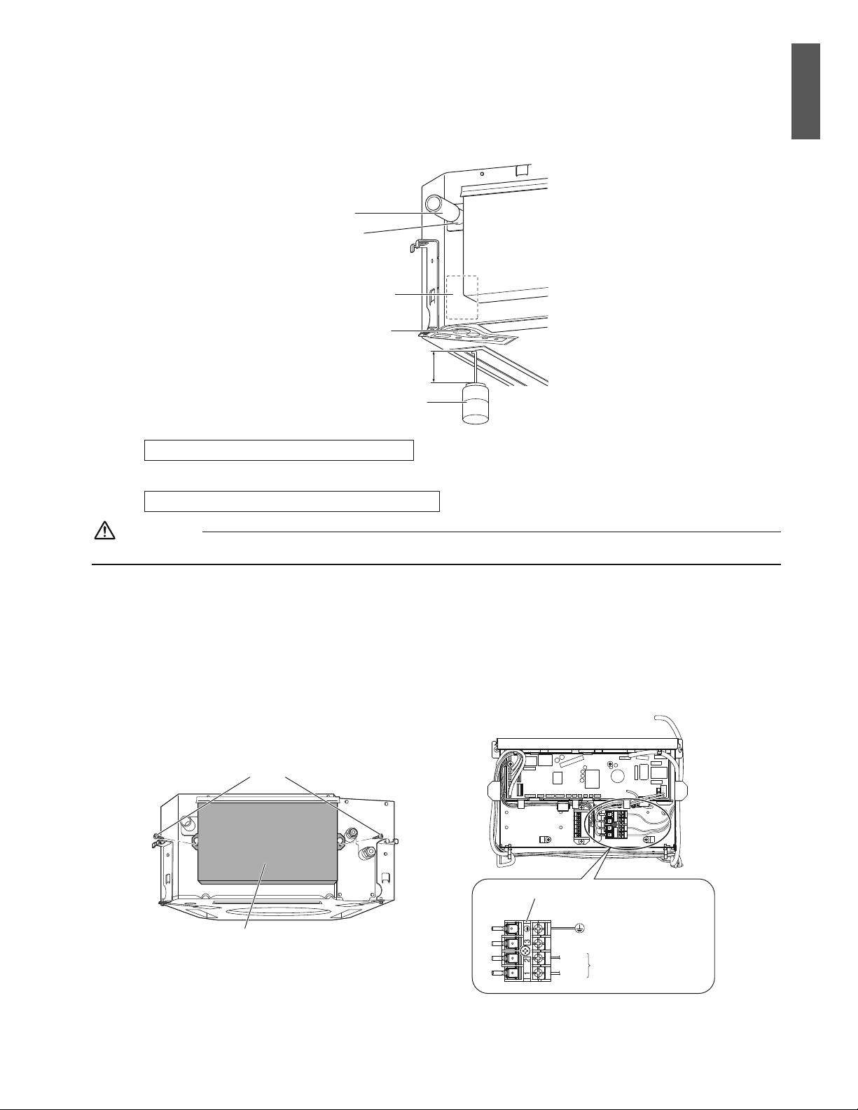
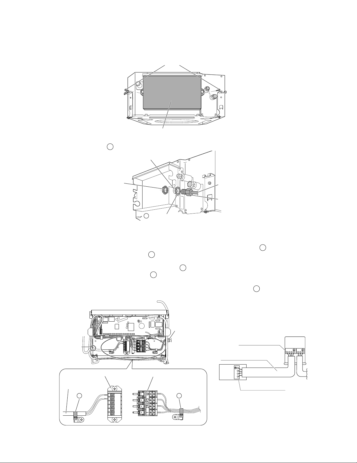
%QPPGEVKQPQHYKTKPIDGVYGGPWPKVUITQWPFYKTGCPFTGOQVGEQPVTQNNGTYKTKPI
9KTKPIDGVYGGPWPKVUCPFITQWPFYKTG
1) Remove the electrical wiring box cover (2 screws).
Screws
Electrical wiring box cover
2) Insert the wires including the ground wire into the conduit, and secure the conduit to the hole in the electrical wiring box
using a lock nut and the
N
washer for conduit, as shown in the illustration.
Lock nut
ƂGNFUWRRN[
%QPFWKV
ƂGNFUWRRN[
*QNGKPVJGGNGEVTKECN
YKTKPIDQZ
9CUJGTHQTEQPFWKV
N
%QPFWKVRKRG
3) Connect the ground wire to the corresponding terminals.
4) /CVEJYKTGEQNQTUYKVJVGTOKPCNPWODGTUQPVJGVGTOKPCNDNQEMHQTRQYGTUWRRN[QHKPFQQTCPFQWVFQQTWPKVCPFƂTON[
secure the wires in the corresponding terminals with screws.
5) +PFQKPIVJKURWNNVJGYKTGUKPUKFGVJTQWIJVJGJQNGCPFƂZVJGYKTGUUGEWTGN[YKVJVJGKPENWFGF
D
clamp.
6)
Give enough slack to the wires between the
D
clamp and terminal block for power supply.
7) Pull the wires inside through the hole and connect them to the terminal block for remote controller (no polarity).
5GEWTGN[ƂZVJGTGOQVGEQPVTQNNGTYKTKPIYKVJVJGKPENWFGF
D
clamp.
8) Give enough slack to the wires between the
D
clamp and the terminal block for remote controller.
9) Attach the electrical wiring box cover as before.
10) #HVGTCNNYKTKPIEQPPGEVKQPUCTGFQPGƂNNKPCP[ICRUKPVJGECUKPIYKTKPIJQNGUYKVJRWVV[QT
M
sealing pad (small) thus
to prevent small animals or dirt from entering the unit from outside and causing short circuits in the electrical wiring box.
Terminal block for remote controller
Clamp
D
Terminal block for power supply
Clamp
D
Opening for cable
Remote controller wiring
Conduit
123
123
L1 L
2
(KTON[ƂZVJGYKTGUYKVJ
VJGVGTOKPCNUETGYU
1WVFQQT
WPKV
+PFQQT
WPKV
(KTON[ƂZVJGYKTGUYKVJ
VJGVGTOKPCNUETGYU
9KTGUK\GCPFNGPIVJOWUV
EQORN[YKVJNQECNEQFGU
14ŶEnglish
Refrigerant Piping Work
4GHGTCNUQVQVJGKPUVCNNCVKQPOCPWCNHQTVJGQWVFQQTWPKV
WARNING
r &QPQVCRRN[OKPGTCNQKNQPƃCTGFRCTV
r Prevent mineral oil from getting into the system as this would reduce the service life of the units.
r Never use piping which has been used for previous installations. Only use parts which are delivered with the unit.
r Never install a dryer to this R410A unit in order to guarantee its service life.
r The drying material may dissolve and damage the system.
r +PEQORNGVGƃCTKPIOC[TGUWNVKPTGHTKIGTCPVICUNGCMCIG
'ZGEWVGVJGTOCNKPUWNCVKQPYQTMEQORNGVGN[QPDQVJUKFGUQHVJGICUCPFVJGNKSWKFRKRKPI1VJGTYKUGCYCVGTNGCMCIGECP
TGUWNVUQOGVKOGU
$GUWTGVQWUGKPUWNCVKQPFGUKIPGFHQTWUGYKVJ*8#%U[UVGOU
#NUQKPECUGUYJGTGVJGVGORGTCVWTGCPFJWOKFKV[QHVJGTGHTKIGTCPVRKRKPIUGEVKQPUOKIJVGZEGGF(%QT4*
TGKPHQTEGVJGTGHTKIGTCPVKPUWNCVKQPKPEJOOQTVJKEMGT%QPFGPUCVKQPOC[HQTOQPVJGUWTHCEGQHVJGKPUWNCVKPI
OCVGTKCN
$GHQTGTGHTKIGTCPVRKRKPIYQTMEJGEMYJKEJV[RGQHTGHTKIGTCPVKUWUGF2TQRGTQRGTCVKQPKUPQVRQUUKDNGKHVJGV[RGUQH
TGHTKIGTCPVCTGPQVVJGUCOG
1. Flaring the pipe end
1) Cut the pipe end with a pipe cutter.
2) Remove burrs with the cut surface facing downward
UQVJCVVJGƂNKPIUFQPQVGPVGTVJGRKRG
3) 2WVVJGƃCTGPWVQPVJGRKRG
4) Flare the pipe.
5) %JGEMVJCVVJGƃCTKPIJCUDGGPFQPGEQTTGEVN[
A
A
Cut exactly at
right angles.
Remove burrs.
Flaring
Set exactly at the position shown below.
Die
0-0.020 inch
(0-0.5mm)
Clutch-type
Flare tool for
R410A
0.039-0.059 inch
(1.0-1.5mm)
Clutch-type
(Rigid-type)
0.059-0.079 inch
(1.5-2.0mm)
Wing-nut type
(Imperial-type)
%QPXGPVKQPCNƃCTGVQQN
6JGƃCTGUKPPGT
surface must be
ƃCYHTGG
The pipe end must
DGGXGPN[ƃCTGFKPC
perfect circle.
Make sure that the
ƃCTGPWVKUƂVVGF
Check
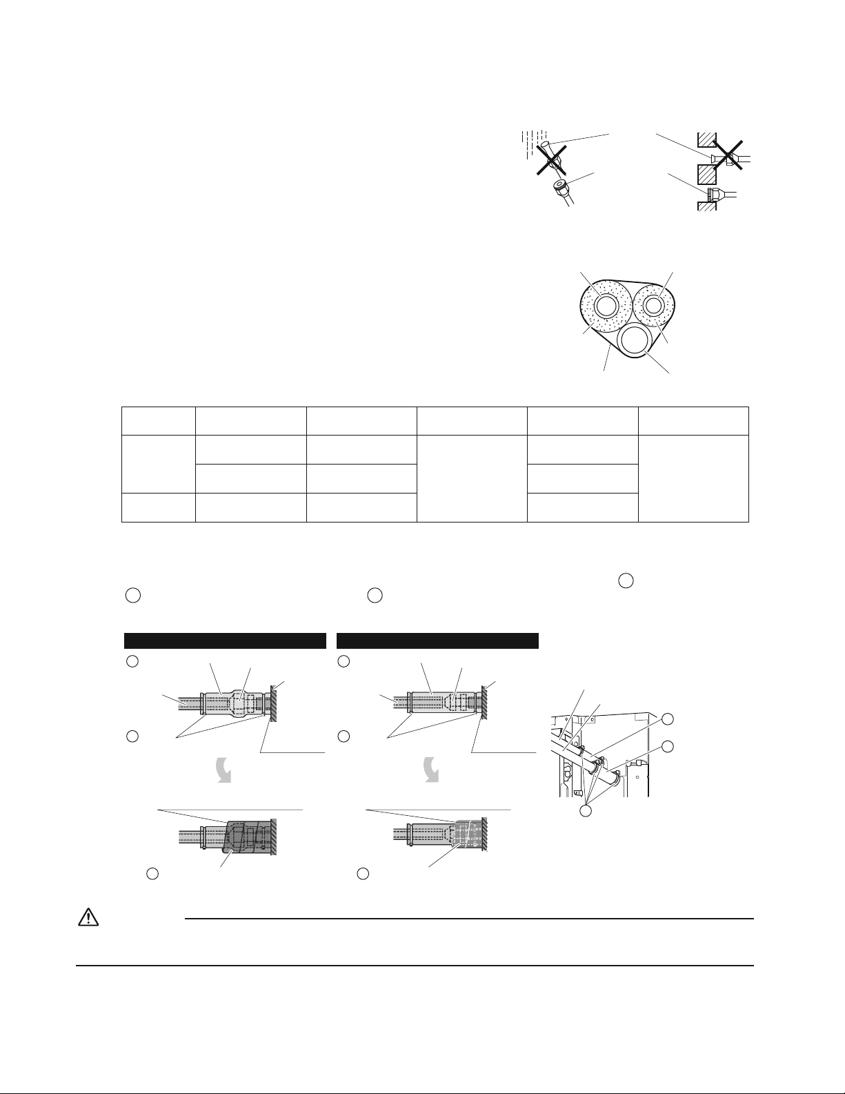
2. Refrigerant piping
CAUTION
r Use the flare nut fixed to the main unit. (This is to prevent the flare nut from cracking as a result of deterioration over time.)
r To prevent gas leakage, apply refrigeration oil only to the inner surface of the flare. (Use refrigeration oil for R410A.)
r Use a torque wrench when tightening the flare nuts to prevent damage to the flare nuts and gas leakage.
r #NKIPVJGEGPVGTUQHDQVJƃCTGUCPFVKIJVGPVJGƃCTGPWVUQTVWTPUD[JCPFVJGPVKIJVGPVJGOHWNN[YKVJCURCPPGTCPF
a torque wrench.
Do not apply refrigeration
oil to the outer surface.
Flare nut
Apply refrigeration
oil only to the inner
UWTHCEGQHVJGƃCTG
Do not apply refrigeration oil to
VJGƃCTGPWVVQCXQKFVKIJVGPKPI
YKVJGZEGUUKXGVQTSWG
Apply oil
6QTSWGYTGPEJ
Piping union
Flare nut
Spanner
Tighten
Piping size Flare nut tightening torque
Gas side
O.D. 3/8 inch (9.5mm) s+DHrHV0rO
O.D. 1/2 inch (12.7mm) s+DHrHV0rO
Liquid side O.D. 1/4 inch (6.4mm) s+DHrHV0rO
English
15 ŶEnglish
Refrigerant Piping Work
Cautions on piping handling
r Protect the open end of the pipe from dust and moisture.
r All pipe bends should be as gentle as possible. Use a pipe bender for
bending.
Wall
+HPQƃCTGECRKU
CXCKNCDNGEQXGTVJG
ƃCTGOQWVJYKVJ
VCRGVQMGGRFKTV
CPFYCVGTQWV
4CKP
$GUWTGVQ
RNCEGCECR
5GNGEVKQPQHEQRRGTCPFJGCVKPUWNCVKQPOCVGTKCNU
9JGPWUKPIEQOOGTEKCNEQRRGTRKRGUCPFƂVVKPIUQDUGTXGVJGHQNNQYKPI
r Insulation material: Polyethylene foam
Heat transfer rate: 0.041 to 0.052W/mK (0.024 to 0.030Btu/fth°F (0.035 to
0.045kcal/mh°C))
$GUWTGVQWUGKPUWNCVKQPVJCVKUFGUKIPGFHQTWUGYKVJ*8#%5[UVGOU
r ACR Copper pipe only.
Gas pipe
Liquid pipe
Gas pipe
insulation
Liquid pipe
insulation
Finishing tape
Drain hose
r Be sure to insulate both the gas and liquid piping and observe the insulation dimensions as below.
Piping size
Minimum bend
radius
Piping thickness
Thermal insulation
size
Thermal insulation
thickness
Gas side
O.D. 3/8 inch
(9.5mm)
1-3/16 inch (30mm)
or more
0.031 inch (0.8mm)
(C1220T-O)
I.D. 15/32-19/32 inch
(12-15mm)
13/32 inch
(10mm) Min.
O.D. 1/2 inch
(12.7mm)
1-9/16 inch (40mm)
or more
I.D. 9/16-5/8 inch
(14-16mm)
Liquid side
O.D. 1/4 inch
(6.4mm)
1-3/16 inch (30mm)
or more
I.D. 5/16-13/32 inch
(8-10mm)
r Use separate thermal insulation pipes for gas and liquid refrigerant pipes.
r Make absolutely sure to execute thermal insulation works on the pipe-connecting section, after checking for gas leakage,
D[VJQTQWIJN[UVWF[KPIVJGHQNNQYKPIƂIWTGUCPFWUKPIVJGKPENWFGFVJGTOCNKPUWNCVKPIOCVGTKCNU
G
ƂVVKPIKPUWNCVKQPCPF
H
ƂVVKPIKPUWNCVKQP(CUVGPDQVJGPFUYKVJVJG
D
clamps.
Piping insulation procedure
Gas piping Liquid piping
Clamps
(use 2 clamps per insulation)
D
Medium 1 sealing pad for gas piping K Medium 2 sealing pad for liquid piping L
Fitting insulation
(for liquid pipe)
HFitting insulation
(for gas pipe)
G
Gas
piping
Main unit
Attach to base
Flare nut connection
Clamps
(use 2 clamps per insulation)
D
Liquid
piping
Main unit
Attach to base
Flare nut connection
Wrap over from the base of the unit
to the top of the ƃare nut connection
Wrap over from the base of the unit
to the top of the ƃare nut connection
Gas pipe
Liquid pipe
Clamps (use 2 clamps per insulation)D
Fitting insulation
(for liquid pipe)
H
Fitting insulation
(for gas pipe)
G
CAUTION
$GUWTGVQKPUWNCVGCP[ƂGNFRKRKPICNNVJGYC[VQVJGRKRKPIEQPPGEVKQPKPUKFGVJGWPKV#P[GZRQUGFRKRKPIOC[ECWUG
condensation or burns if touched.
16ŶEnglish
Installation of the Decoration Panel
9KVJVJGYKTGNGUUTGOQVGEQPVTQNNGTƂGNFUGVVKPICPFVTKCNQRGTCVKQPECPPQVDGRGTHQTOGFYKVJQWVCVVCEJKPIVJGFGEQTCVKQP
panel.
Read p6TKCN1RGTCVKQPCPF6GUVKPIq before making a trial operation without attaching the decoration panel.
Refer to the installation manual attached to the decoration panel.
After installing the decoration panel, ensure that there is no space between the unit body and decoration panel.
Field Settings
CAUTION
When performing field setting or trial operation without attaching the decoration panel, do not touch the drain pump. This may
cause electric shock.
r /CMGUWTGVJGGNGEVTKECNYKTKPIDQZEQXGTKUENQUGFQPVJGKPFQQTCPFQWVFQQTWPKVU
r (KGNFUGVVKPIUOWUVDGOCFGHTQOVJGTGOQVGEQPVTQNNGTCPFKPCEEQTFCPEGYKVJ
installation conditions.
r 5GVVKPIECPDGOCFGD[EJCPIKPIVJGp/QFG0Qqp(+456%1&'01qCPFp5'%10&
%1&'01q
r The “Field Settings” included with the remote control lists the order of the settings and
method of operation.
Unit No
0
1
–
01
5
–––
9
–––
13
–––
2
–
02
6
–––
10
–––
14
–––
3
–
01
7
–––
11
–––
15
–––
Field Settings
0
–
01
4
–––
8
–––
12
–––
Setting
Mode
20
1. Setting air outlet direction
r For changing air outlet direction (2 or 3 directions), refer to the installation manual attached to the blocking pad kit (sold
separately) or the service manual.
5'%10&%1&'01KUHCEVQT[UGVVQpqHQTCKTQWVNGVKPFKTGEVKQPU
2. Setting for options
r For settings for options, see the installation manual provided with the option.
3. 5GVVKPICKTƂNVGTUKIP
r 4GOQVGEQPVTQNNGTUCTGGSWKRRGFYKVJNKSWKFET[UVCNFKURNC[CKTƂNVGTUKIPUVQFKURNC[VJGVKOGVQENGCPCKTƂNVGTU
r %JCPIGVJG5'%10&%1&'01FGRGPFKPIQPVJGCOQWPVQHFKTVQTFWUVKPVJGTQQO
5'%10&%1&'01KUHCEVQT[UGVVQpqHQTCKTƂNVGTEQPVCOKPCVKQPNKIJV
Setting
6KOGWPVKN#+4(+.6'4%.'#0+0)
6+/'+0&+%#614NCORNKIJVUWR
(Long life type)
Mode No.
FIRST
%1&'01
5'%10&
%1&'01
#KTƂNVGTEQPVCOKPCVKQPNKIJV Approx. 2500 hrs
10 (20)
0
01
#KTƂNVGTEQPVCOKPCVKQPJGCX[ Approx. 1250 hrs 02
Display on
–3
01
Display off 02
9JGPWUKPIYKTGNGUUTGOQVGEQPVTQNNGTU
r When using the wireless remote controllers, wireless remote controller address setting is necessary. Refer to the
installation manual attached to the wireless remote controller.
English
17 ŶEnglish
Field Settings
4. 9JGPKORNGOGPVKPIITQWREQPVTQN
r When using as a pair unit, you may control up to 16 units
with the remote controller.
r In this case, all the indoor units in the group will operate in
accordance with the group control remote controller.
r Select a remote controller which matches as many of the
HWPEVKQPUUYKPIƃCRGVEKPVJGITQWRCURQUUKDNG
Outdoor unit 1 Outdoor unit 2 Outdoor unit 3
Indoor unit 1 Indoor unit 2
Group control remote controller
Indoor unit 3
Wiring Method (Refer to p9KTKPIq on page 11.)
1) Remove the electrical wiring box cover.
2) Cross-wire the terminal block for remote controller (P
1, P2) inside the electrical wiring box. (There is no polarity.)
(Refer to Table 3 in p9KTKPIq on page 12)
5. TGOQVGEQPVTQNNGTUEQPVTQNNKPIKPFQQTWPKVD[TGOQVGEQPVTQNNGTU
r When using 2 remote controllers, one must be set to “MAIN” and the other to “SUB”.
Wiring Method (Refer to p9KTKPIq on page11.)
1) Remove the electrical wiring box cover.
2)
Add remote controller 2 to the terminal block for remote controller (P1, P2) in the electrical wiring box. (There is no polarity.)
(Refer to Table 3 in p9KTKPIq on page 12)
Trial Operation and Testing
CAUTION
9JGPRGTHQTOKPIƂGNFUGVVKPIUQTVTKCNQRGTCVKQPYKVJQWVCVVCEJKPIVJGFGEQTCVKQPRCPGNFQPQVVQWEJVJGFTCKPRWOR6JKUOC[
cause electric shock.
r #HVGTƂPKUJKPIVJGEQPUVTWEVKQPQHTGHTKIGTCPVRKRKPIFTCKPRKRKPICPFGNGEVTKEYKTKPIEQPFWEVVTKCNQRGTCVKQPCEEQTFKPIN[VQRTQVGEV
the unit.
1. Trial operation and testing
Make sure to install the decoration panel before carrying out trial operation if the wireless remote controller is used.
r 6TKCNQRGTCVKQPUJQWNFDGECTTKGFQWVKPGKVJGT%11.QT*'#6QRGTCVKQP
/GCUWTGVJGUWRRN[XQNVCIGCPFOCMGUWTGVJCVKVKUYKVJKPVJGURGEKƂGFTCPIG
+P%11.QRGTCVKQPUGNGEVVJGNQYGUVRTQITCOOCDNGVGORGTCVWTG
KP*'#6QRGTCVKQPUGNGEVVJGJKIJGUVRTQITCOOCDNGVGORGTCVWTG
%CTT[QWVVJGVTKCNQRGTCVKQPHQNNQYKPIVJGKPUVTWEVKQPUKPVJGQRGTCVKQPOCPWCN
VQGPUWTGVJCVCNNHWPEVKQPUCPFRCTVUUWEJCUVJGOQXGOGPVQHVJGNQWXGTUCTG
YQTMKPIRTQRGTN[
r To protect the air conditioner, restart operation is disabled for 3 minutes after the system has been turned off.
1-4.
#HVGTVTKCNQRGTCVKQPKUEQORNGVGUGVVJGVGORGTCVWTGVQCPQTOCNNGXGN(VQ(
%VQ%KP%11.QRGTCVKQP(VQ(%VQ%KP*'#6QRGTCVKQP
r 9JGPQRGTCVKPIVJGCKTEQPFKVKQPGTKP%11.QRGTCVKQPKPYKPVGTQT*'#6QRGTCVKQPKPUWOOGTUGVKVVQVJGVTKCNQRGTCVKQP
mode using the following method.
Refer to
(QTYKTGFTGOQVGEQPVTQNNGT
on page 18.
Refer to
(QTYKTGNGUUTGOQVGEQPVTQNNGT
on page 19.

18ŶEnglish
Basic screen
1)
2)
Cool
Return %NGCPVJGƂNVGT
Set to
Cool
68F
Press and hold Cancel
button for 4 seconds or
longer during backlight lit.
5GTXKEG5GVVKPIU
OGPWUETGGP
3)
Setting
1/3
Service Settings
Test Operation
Maintenance Contact
Field Settings
Energy Saving Options
Prohibit Buttons
Min Setpoints Differential
Press Menu/OK button.
4)
5)
Set temperature
80°F
Cool
Test Operation
Press On/Off button
(within 10 seconds).
Press Menu/OK button.
/CKPOGPWUETGGP
6)
Setting
MainMenu
Air Flow Direction
Ventilation
Schedule
Off Timer
Celsius / Fahrenheit
Maintenance Information
1/2
Press Menu/OK button.
7)
Setting
Air Flow Direction
Swing
%JCPIGVJGCKTƃQY
direction by using
(Up/Down)button.
Press Menu/OK button.
8)
Set temperature
80°F
Cool
Test Operation
Press and hold Cancel
button for 4 seconds or
longer during backlight lit.
9)
Setting
1/3
Service Settings
Test Operation
Maintenance Contact
Field Settings
Energy Saving Options
Prohibit Buttons
Min Setpoints Differential
Press Menu/OK button.
Basic screen
(QTYKTGFTGOQVGEQPVTQNNGT
1) 5GVVQ%11.QT*'#6QRGTCVKQPWUKPIVJGTGOQVG
controller.
2) 2TGUUCPFJQNF%CPEGNDWVVQPHQT|UGEQPFUQTNQPIGT
Service settings menu is displayed.
3) Select Test Operation in the service settings menu, and
press Menu/OK button. Basic screen returns and “Test
Operation” is displayed at the bottom.
4) 2TGUU1P1HHDWVVQPYKVJKP|UGEQPFUCPFVJGVGUV
operation starts.
Monitor the operation of the indoor unit for a minimum
of 10 minutes. During test operation, the indoor unit
will continue to cool/heat regardless of the temperature
setpoint and room temperature.
r In the case of above-mentioned procedures 3) and 4)
in reverse order, test operation can start as well.
5) Press Menu/OK button in the basic screen. Main menu is
displayed.
6) Select Air Flow Direction in the main menu and check
VJCVCKTƃQYFKTGEVKQPKUCEVWCVGFCEEQTFKPIVQVJGUGVVKPI
(QTQRGTCVKQPQHCKTƃQYFKTGEVKQPUGVVKPIUGGVJG
operation manual.
7) #HVGTVJGQRGTCVKQPQHCKTƃQYFKTGEVKQPKUEQPƂTOGF
press Menu/OK button. Basic screen returns.
8) 2TGUUCPFJQNF%CPEGNDWVVQPHQT|UGEQPFUQTNQPIGTKP
the basic screen.
Service settings menu is displayed.
9) Select Test Operation in the service settings menu, and
press Menu/OK button. Basic screen returns and normal
operation is conducted.
r Test operation will stop automatically after 15-30
minutes. To stop the operation, press On/Off button.
10) If the decoration panel has not been installed, turn off the
power after the test operation.
English

19 ŶEnglish
Trial Operation and Testing
(QTYKTGNGUUTGOQVGEQPVTQNNGT
1) Press
MODE
CPFUGNGEVVJG%11.QT*'#6QRGTCVKQP
2) Press
/TEST
twice. “Test” is displayed.
3) Press
ON OFF
within 10 seconds, and the test operation starts.
Monitor the operation of the indoor unit for a minimum of 10 minutes. During test operation, the indoor unit will continue to
cool/heat regardless of the temperature setpoint and room temperature.
r In the case of above-mentioned procedures 1) and 2) in reverse order, test operation can start as well.
r Test operation will stop automatically after 15 - 30 minutes. To stop the operation, press
ON OFF
.
r Some of the functions cannot be used in the test operation mode.
Precautions
1) Refer to p*QYVQFKCIPQUGHQTOCNHWPEVKQPq if the unit does not operate properly.
2. 6GUVKVGOU
Test items Symptom Check
Indoor and outdoor units are installed securely. Fall, vibration, noise
Is the outdoor unit fully installed? No operation or burn damage
No refrigerant gas leaks. Incomplete cooling/heating function
Refrigerant gas and liquid pipes and indoor drain hose
extension are thermally insulated.
Water leakage
Draining line is properly installed. Water leakage
Does the power supply voltage correspond to that
shown on the name plate?
No operation or burn damage
1PN[URGEKƂGFYKTGUCTGWUGFHQTCNNYKTKPICPFCNN
wires are connected correctly.
No operation or burn damage
System is properly grounded. 'NGEVTKECNNGCMCIG
+UYKTKPIUK\GCEEQTFKPIVQURGEKƂECVKQPU! No operation or burn damage
Is something blocking the air outlet or inlet of either the
indoor or outdoor units?
Incomplete cooling/heating function
Are refrigerant piping length and additional refrigerant
charge noted down?
The refrigerant charge in the system is not clear
Pipes and wires are connected to the corresponding
connection ports / terminal blocks for the connected unit.
No cooling/heating
Stop valves are opened. Incomplete cooling/heating function
Check that the connector of the lead wires of the
decoration panel is connected securely.
Louvers do not move
Indoor unit properly receives wireless remote control
commands.
No operation
+VGOUVQDGEJGEMGFCVVKOGQHFGNKXGT[
Also review the p2TGECWVKQPUq on page 3
Test items Check
#TGVJGGNGEVTKECNYKTKPIDQZEQXGTCKTƂNVGTUWEVKQPITKNNGCVVCEJGF!
Did you explain about operations while showing the operation manual to your customer?
Did you hand the operation manual over to your customer?
2QKPVUHQTGZRNCPCVKQPCDQWVQRGTCVKQPU
The items with WARNING and CAUTION marks in the operation manual are the items pertaining to possibilities for bodily
injury and material damage in addition to the general usage of the product. Accordingly, it is necessary that you make a full
explanation about the described contents and also ask your customers to read the operation manual.
20ŶEnglish
Note to the installer
$GUWTGVQKPUVTWEVEWUVQOGTUJQYVQRTQRGTN[QRGTCVGVJGWPKVGURGEKCNN[ENGCPKPIVJGƂNVGTQRGTCVKPIFKHHGTGPVHWPEVKQPUCPF
adjusting the temperature) by having them carry out operations while looking at the manual.
3. *QYVQFKCIPQUGHQTOCNHWPEVKQP
r If the air conditioner does not operate normally after installing the air conditioner, a malfunction shown in the table below may
happen.
Wired remote controller display Description
No display
r Power outage, power voltage error or open-phase
r Incorrect wiring (between indoor and outdoor units)
r Indoor PC-board assembly failure
r Remote controller wiring not connected
r Remote controller failure
r Open fuse or tripped circuit breaker (outdoor unit)
“Checking the connection. Please
stand by.” *
r Indoor PC-board assembly failure
r Wrong wiring (between indoor and outdoor units)
* “Checking the connection. Please stand by” will be displayed for up to 90 seconds following the application of power to the indoor
unit. This is normal and does not indicate a malfunction.
Diagnose with the display on the liquid crystal display remote controller.
9KVJVJGYKTGFTGOQVGEQPVTQNNGT
When the operation stops due to a malfunction, operation lamp blinks, and the malfunction code is indicated on the liquid crystal
display. In such a case, diagnose the fault contents by referring to
'TTQT*KUVQT[ in the service settings menu.
+PVJGECUGQHITQWREQPVTQNVJGWPKV0QKUFKURNC[GFUQVJCVVJGKPFQQTWPKVYKVJVJGVTQWDNGECPDGKFGPVKƂGF
9KVJVJGYKTGNGUUTGOQVGEQPVTQNNGT
(Refer also to the operation manual attached to the wireless remote controller)
When the operation stops due to a malfunction the display on the indoor unit blinks. In such a case, diagnose the fault contents with
the error code which can be found by following procedures.
1) 2TGUUVJG+052'%6+106'5612'4#6+10DWVVQPp
” is displayed and “ 0 ” blinks.
2) 2TGUUVJG6'/2'4#674'5'66+0)DWVVQPCPFƂPFVJGWPKV0QYJKEJUVQRRGFFWGVQVTQWDNG
Number of beeps 3 short beeps .............................
1 short beep ..............................
1 long beep ................................
Perform all the following operations
Perform (3) and (6)
No trouble
3) 2TGUUVJG12'4#6+10/1&'5'.'%614DWVVQPCPFWRRGTƂIWTGQHVJGGTTQTEQFGDNKPMU
4) %QPVKPWGRTGUUKPIVJG6'/2'4#674'5'66+0)DWVVQPWPVKNKVOCMGUUJQTVDGGRUCPFƂPFVJGWRRGTEQFG
5) 2TGUUVJG12'4#6+10/1&'5'.'%614DWVVQPCPFNQYGTƂIWTGQHVJGGTTQTEQFGDNKPMU
6) %QPVKPWGRTGUUKPIVJG6'/2'4#674'5'66+0)DWVVQPWPVKNKVOCMGUCNQPIDGGRCPFƂPFVJGNQYGTEQFG
rA long beep indicate the error code.
English
1 ŶFrançais
Considérations sur la sécurité
Lisez soigneusement ces Considérations sur la sécurité pour
l’installation avant d’installer un climatiseur ou une pompe à
chaleur. Après avoir complété l’installation, assurez-vous que
l’unité fonctionne correctement pendant l’opération de démarrage.
Former l’utilisateur sur la façon d’exploiter et d’entretenir l’unité.
Informer les utilisateurs qu’ils doivent conserver ce manuel
d’installation avec le manuel d’utilisation pour référence ultérieure.
Utilisez toujours un installateur ou un entrepreneur agréé pour
installer ce produit.
Une mauvaise installation peut provoquer une fuite d’eau ou de
réfrigérant, une électrocution, un incendie ou une explosion.
5KIPKƂECVKQPFGUU[ODQNGUDANGER, AVERTISSEMENT,
ATTENTION, et AVIS :
DANGER
...........
Indique une situation extrêmement
dangereuse qui, si elle n’est pas
évitée, entraînera la mort ou des
DNGUUWTGUITCXGU
AVERTISSEMENT
...
Indique une situation
potentiellement dangereuse qui, si
elle n’est pas évitée, peut entraîner
NCOQTVQWFGUDNGUUWTGUITCXGU
ATTENTION
......
Indique une situation potentiellement
dangereuse qui, si elle n’est pas
ÅXKVÅGRGWVGPVTCÊPGTFGUDNGUUWTGU
mineures à modérées. Il peut
également être utilisé pour alerter
contre des pratiques dangereuses.
AVIS
..................
Indique des situations pouvant
provoquer des accidents et
l’endommagement de l’équipement
ou des dégâts matériels seulement.
DANGER
r
.GIC\TÅHTKIÅTCPVGUVRNWUNQWTFSWGNoCKTGVTGORNCEGNoQZ[IÄPG
Une fuite importante peut conduire à un appauvrissement en
QZ[IÄPGGPRCTVKEWNKGTGPUQWUUQNGVWPTKUSWGFoCURJ[ZKG
RGWVUWTXGPKTGVGPVTCÊPGTFGUDNGUUWTGUITCXGUQWNCOQTV
r
0GTGNKG\RCUNGUWPKVÅU¼FGUEQPFWKVGUFoGCW¼FGUVW[CWZ
FGIC\¼FGUE¾DNGUVÅNÅRJQPKSWGUQW¼FGURCTCVQPPGTTGU
car une mise à la terre incomplète pourrait provoquer un
risque d’électrocution important pouvant entraîner des
DNGUUWTGUITCXGUQWNCOQTV&GRNWUTGNKGTFGUVW[CWZ
de gaz peut provoquer une fuite de gaz, une explosion
RQVGPVKGNNGGPVTCÊPCPVFGUDNGUUWTGUITCXGUQWNCOQTV
r Si vous constatez des fuites de gaz réfrigérant pendant
l’installation, aérez immédiatement la zone. Le gaz
réfrigérant peut produire un gaz toxique s’il entre en
EQPVCEVCXGEWPGƃCOOG.oGZRQUKVKQP¼EGIC\RGWV
RTQXQSWGTFGUDNGUUWTGUITCXGUQWNCOQTV
r #RTÄUNoCEJÄXGOGPVFGUVTCXCWZFoKPUVCNNCVKQPXÅTKƂG\SWG
NGIC\TÅHTKIÅTCPVPGHWKVRCU¼VTCXGTUNGU[UVÄOG
r
N’installez pas une unité dans un endroit où des matériaux
KPƃCOOCDNGUUQPVRTÅUGPVUGPTCKUQPFWTKUSWGFoGZRNQUKQP
RQWXCPVGPVTCÊPGTFGUDNGUUWTGUITCXGUQWNCOQTV
r &KURQUG\FGHCÃQPUÅEWTKVCKTGVQWUNGUOCVÅTKCWZ
FoGODCNNCIGGVFGVTCPURQTVEQPHQTOÅOGPVCWZNQKUGV
réglementations fédérales, étatiques et locales. Les
OCVÅTKCWZFoGODCNNCIGVGNUSWGFGUENQWUGVCWVTGU
RKÄEGUOÅVCNNKSWGUQWGPDQKU[EQORTKUNGUOCVÅTKCWZ
FoGODCNNCIGGPRNCUVKSWGWVKNKUÅURQWTNGVTCPURQTVRGWXGPV
ECWUGTFGUDNGUUWTGUQWNCOQTVRCTUWHHQECVKQP
AVERTISSEMENT
r
5GWNNGRGTUQPPGNSWCNKƂÅFQKVGHHGEVWGTNGUVTCXCWZ
d’installation. L’installation doit être effectuée conformément
à ce manuel d’installation. Une mauvaise installation peut
entraîner une fuite d’eau, une électrocution, ou un incendie.
r
Lors de l’installation de cette unité dans une petite pièce, prenez
des mesures pour maintenir la concentration de réfrigérant en
dessous des limites de sécurité admises. Les fuites excessives
de réfrigérant, dans le cas d’un accident dans un espace
CODKCPVENQURGWXGPVEQPFWKTG¼WPGECTGPEGGPQZ[IÄPG
r 7VKNKUG\UGWNGOGPVNGUCEEGUUQKTGUGVNGURKÄEGUURÅEKƂÅU
pour les travaux d’installation. Ne pas utiliser les
RKÄEGUURÅEKƂÅGURGWVGPVTCÊPGTFGUHWKVGUFoGCWWPG
électrocution, un incendie ou la chute de l’unité.
r
Installez le climatiseur ou la pompe à chaleur sur une
HQPFCVKQPUWHƂUCOOGPVUQNKFGRQWTSWoGNNGRWKUUGUWRRQTVGT
NGRQKFUFGNoWPKVÅ7PGHQPFCVKQPFGTÅUKUVCPEGKPUWHƂUCPVG
RGWVGPVTCÊPGTNCEJWVGFGNoWPKVÅGVECWUGTFGUDNGUUWTGU
r
Lors de l’installation, prenez en compte les vents forts, les
Sommaire
Considérations sur la sécurité ...................... 1
Avant l’installation .......................................... 3
Accessoires ..................................................... 3
Choix du site de l’installation ........................ 4
Installation de l’unité intérieure ..................... 6
1. Lien entre l’ouverture au plafond et l’unité, et
RQUKVKQPPGOGPVFWDQWNQPFGUWURGPUKQP ................... 6
2. Le cas échéant, faire l’ouverture au plafond
nécessaire pour l’installation
(Pour les plafonds existants) ....................................... 7
+PUVCNNCVKQPFGUDQWNQPUFGUWURGPUKQP ....................... 7
4. Installation de l’unité intérieure .................................... 7
6TCXCKNFGNCVW[CWVGTKGFoÅXCEWCVKQP ............................ 8
%¾DNCIG ....................................................................... 11
Travaux de tuyauterie de réfrigérant ............. 14
¥XCUGOGPVFGNoGZVTÅOKVÅFWVW[CW .............................. 14
6W[CWVGTKGFGTÅHTKIÅTCPV.............................................. 14
Installation du Panneau de Décoration ........ 16
Paramètres de champ .................................... 16
1. Réglage de la direction de sortie d’air ......................... 16
2. Réglage des options .................................................... 16
4ÅINCIGFGUKPFKEGUFWƂNVTG¼CKT ............................... 16
4. Lors de la mise en œuvre du contrôle de groupe ........ 17
5. 2 télécommandes (contrôler 1 unité intérieure avec
2 télécommandes) ....................................................... 17
Fonctionnement d’essai et test ..................... 17
1. Fonctionnement d’essai et test .................................... 17
2. Éléments testés ........................................................... 19
%QOOGPVFKCIPQUVKSWGTNGUF[UHQPEVKQPPGOGPVU ........ 20

2ŶFrançais
V[RJQPUQWNGUVTGODNGOGPVUFGVGTTG7PGOCWXCKUGKPUVCNNCVKQP
peut provoquer la chute de l’unité et causer des accidents.
r
Assurez-vous qu’un circuit d’alimentation électrique séparé est
prévu pour cette unité et que tous les travaux d’électricité sont
TÅCNKUÅURCTFWRGTUQPPGNSWCNKƂÅUGNQPNGUTÅINGOGPVCVKQPU
locales, étatiques et nationales. Une puissance d’alimentation
ÅNGEVTKSWGKPUWHƂUCPVGQWWPGKPUVCNNCVKQPÅNGEVTKSWGKPCFCRVÅG
peut conduire à un choc électrique ou un incendie.
r
#UUWTG\XQWUSWGVQWVNGE¾DNCIGGUVUÅEWTKUÅSWGNGUE¾DNGU
URÅEKƂÅUUQPVWVKNKUÅUGVSWoCWEWPGHQTEGGZVÅTKGWTGPoCIKUUGUWT
NGUEQPPGEVKQPUQWE¾DNGUFGUDQTPGU&GOCWXCKUGUEQPPGZKQPU
ou une installation inadaptée peuvent provoquer un incendie.
r
.QTUFWE¾DNCIGRQUKVKQPPG\NGUE¾DNGUFGOCPKÄTG¼EG
SWGNGEQWXGTENGFWDQÊVKGTFGE¾DNCIGÅNGEVTKSWGRWKUUG
ÆVTGƂZÅUQNKFGOGPV7POCWXCKURQUKVKQPPGOGPVFW
EQWXGTENGFWDQÊVKGTFGE¾DNCIGÅNGEVTKSWGRGWVGPVTCÊPGT
WPGÅNGEVTQEWVKQPWPKPEGPFKGQWNCUWTEJCWHHGFGUDQTPGU
r
Avant de toucher les parties électriques, mettez l’unité hors tension.
r
Le circuit doit être protégé par des dispositifs de sécurité
conformément aux codes locaux et nationaux en vigueur, à
UCXQKTWPHWUKDNGWPFKULQPEVGWTWPUGEVKQPPGWTQWWP&&(6
r
(KZG\UQNKFGOGPVNGEQWXGTENGFGNCDQTPGFGNoWPKVÅGZVÅTKGWTG
RCPPGCW5KNGEQWXGTENGRCPPGCWFGNCDQTPGPoGUVRCU
correctement installé, la poussière ou l’eau peuvent pénétrer dans
l’unité extérieure provoquant un incendie ou une électrocution.
r
.QTUFGNoKPUVCNNCVKQPQWFWFÅRNCEGOGPVFWU[UVÄOG
OCKPVGPG\NGEKTEWKVTÅHTKIÅTCPVGZGORVFGUWDUVCPEGU
CWVTGUSWGNGTÅHTKIÅTCPVURÅEKƂÅ4#VGNSWGNoCKT6QWVG
RTÅUGPEGFoCKTQWFoCWVTGUWDUVCPEGÅVTCPIÄTGFCPUNGEKTEWKV
de réfrigérant peut provoquer une augmentation anormale
FGNCRTGUUKQPGPVTCÊPCPVWPGTWRVWTGGVFQPEFGUDNGUUWTGU
r
0GOQFKƂG\RCUNGTÅINCIGFGUFKURQUKVKHUFGRTQVGEVKQP5KNG
commutateur de pression, le commutateur thermique, ou un
autre dispositif de protection sont court-circuités et exploités de
HQTEGQWFGURKÄEGUCWVTGUSWGEGNNGUURÅEKƂÅGURCT&CKMKPUQPV
utilisées, un incendie ou une explosion peuvent se produire.
ATTENTION
r
Ne touchez pas le commutateur avec des doigts mouillés. Toucher un
commutateur avec les doigts mouillés peut provoquer une électrocution.
r Ne laissez pas les enfants jouer sur ou autour de l’unité
RQWTÅXKVGTNGUDNGUUWTGU
r .GUCKNGVVGUFGNoÅEJCPIGWTFGEJCNGWTUQPVUWHƂUCOOGPV
VTCPEJCPVGURQWTEQWRGT2QWTÅXKVGTFGUDNGUUWTGURQTVG\
des gants ou couvrez les ailettes en travaillant à proximité.
r
0GVQWEJG\RCUNGUVW[CWZFGTÅHTKIÅTCPVRGPFCPVGV
KOOÅFKCVGOGPVCRTÄUNGHQPEVKQPPGOGPVECTNGUVW[CWZFG
réfrigérant peuvent être chauds ou froids, en fonction de l’état
FWTÅHTKIÅTCPVEKTEWNCPV¼VTCXGTUNCVW[CWVGTKGFGTÅHTKIÅTCVKQPNG
EQORTGUUGWTGVFoCWVTGURCTVKGUFWE[ENGFGTÅHTKIÅTCVKQP8QU
OCKPURGWXGPVUWDKTFGUDT×NWTGUQWFGUIGNWTGUUKXQWUVQWEJG\
NGUVW[CWZFGTÅHTKIÅTCPV2QWTÅXKVGTNGUDNGUUWTGUNCKUUG\CWZ
VW[CWZNGVGORUFGTGXGPKT¼WPGVGORÅTCVWTGPQTOCNGQWUKXQWU
devez les toucher, assurez-vous de porter des gants appropriés.
r +PUVCNNG\WPGVW[CWVGTKGFoÅXCEWCVKQPRQWTWPGRWTIG
CFÅSWCVG7PGVW[CWVGTKGFoÅXCEWCVKQPKPCFCRVÅGRGWV
entraîner des fuites d’eau et des dégâts matériels.
r +UQNG\NCVW[CWVGTKGRQWTÅXKVGTNCEQPFGPUCVKQP
r 5Q[G\RTWFGPVNQTUFWVTCPURQTVFWRTQFWKV
r Ne pas éteindre l’appareil immédiatement après l’arrêt de
l’opération. Attendez toujours au moins 5 minutes avant
de l’éteindre. Sinon, une fuite d’eau peut se produire.
r
0oWVKNKUG\RCUFGE[NKPFTGFGEJCTIG.oWVKNKUCVKQPFoWPE[NKPFTG
de charge peut provoquer la détérioration du réfrigérant.
r .GTÅHTKIÅTCPV4#FCPUNGU[UVÄOGFQKVÆVTGICTFÅ
propre, sec et scellé.
C0GVVQ[GTGVUÅEJGT'ORÆEJG\NGUOCVKÄTGU
ÅVTCPIÄTGU[EQORTKUNGUJWKNGUOKPÅTCNGUVGNNGUSWG
NoJWKNG570+51QWNoJWOKFKVÅFoGPVTGTFCPUNGU[UVÄOG
D
Sceller -- R410A ne contient pas de chlore, ne détruit pas
la couche d’ozone, et ne réduit pas la protection de la
VGTTGEQPVTGNGTC[QPPGOGPVWNVTCXKQNGVPQEKH4#RGWV
EQPVTKDWGT¼NoGHHGVFGUGTTGUKNKDÅTÅ2CTEQPUÅSWGPV
RTGPG\FGUOGUWTGUCRRTQRTKÅGURQWTXÅTKƂGTNoÅVCPEJÅKVÅ
FGNoKPUVCNNCVKQPFGUVW[CWZFGTÅHTKIÅTCPV.KUG\NGEJCRKVTG
Travaux de tuyauterie de réfrigérant et suivre les procédures.
r
Étant donné que R410A est un mélange, le réfrigérant
supplémentaire nécessaire doit être ajouté à l’état liquide. Si
le réfrigérant est ajouté sous l’état de gaz, sa composition
RGWVEJCPIGTGVNGU[UVÄOGPGHQPEVKQPPGTCRCUEQTTGEVGOGPV
r
.oWPKVÅKPVÅTKGWTGGUVRQWTNG4#8QKTNGECVCNQIWGFGUOQFÄNGU
d’intérieur qui peuvent être connectés. Le fonctionnement normal
GUVKORQUUKDNGNQTUSWGNoWPKVÅGUVEQPPGEVÅG¼FoCWVTGU
r
.CFKUVCPEGFGVTCPUOKUUKQPFGNCVÅNÅEQOOCPFGMKV
UCPUƂNRGWVÆVTGRNWUEQWTVGSWGRTÅXWGFCPUNGURKÄEGU
ÅSWKRÅGUFGNCORGUƃWQTGUEGPVGUÅNGEVTQPKSWGUFGV[RG
onduleur ou à démarrage rapide). Installez l’unité intérieure
CWUUKNQKPFGUNCORGUƃWQTGUEGPVGUSWGRQUUKDNG
r
Les unités intérieures sont pour une installation intérieure seulement.
Les unités extérieures peuvent être installées à l’extérieur ou à
l’intérieur. Cette unité est pour une utilisation intérieure.
r N’installez pas le climatiseur ou la pompe à chaleur dans
les endroits suivants :
(a)
5KWPDTQWKNNCTFFoJWKNGOKPÅTCNGNCRWNXÅTKUCVKQPFoJWKNGQW
de la vapeur sont produits, par exemple, dans une cuisine.
Les pièces en plastique peuvent se détériorer, chuter ou
provoquer des fuites d’eau.
D
Là où des gaz corrosifs, tels que l’acide sulfurique, sont produits.
.CEQTTQUKQPFGUVW[CWZGPEWKXTGQWFGURCTVKGUUQWFÅGURGWV
provoquer des fuites de réfrigérant.
(c)
Près de machines émettant des ondes électromagnétiques.
.GUQPFGUÅNGEVTQOCIPÅVKSWGURGWXGPVRGTVWTDGTNG
HQPEVKQPPGOGPVFWU[UVÄOGFGEQOOCPFGGVRTQXQSWGT
FGUF[UHQPEVKQPPGOGPVUFGNoWPKVÅ
(d)
.¼QÕFGUIC\KPƃCOOCDNGURGWXGPVHWKTN¼QÕKN[CFGNCƂDTG
FGECTDQPGQWFGNCRQWUUKÄTGKPƃCOOCDNGGPUWURGPUKQP
FCPUNoCKTN¼QÕFGUIC\KPƃCOOCDNGUXQNCVKNGUVGNUSWGFGU
diluants ou de l’essence sont manipulés. Faire fonctionner
l’unité dans ces conditions peut provoquer un incendie.
r
Prenez des mesures adéquates pour empêcher que l’unité
GZVÅTKGWTGFGXKGPPGWPCDTKRQWTNGURGVKVUCPKOCWZ.GURGVKVU
animaux qui entrent en contact avec les parties électriques peuvent
RTQXQSWGTFGUF[UHQPEVKQPPGOGPVUFGNCHWOÅGQWWPKPEGPFKG
(QTOGTNoWVKNKUCVGWTCƂPFGOCKPVGPKTNC\QPGRTQRTGCWVQWTFGNoWPKVÅ
AVIS
r
L’unité intérieure devrait être positionnée de manière à ce que
NoWPKVÅGVNGUE¾DNGUKPVGTWPKVÅUFGNoGZVÅTKGWT¼NoKPVÅTKGWTUQKGPV
à une distance d’au moins 3,3ft (1m) de toute télévision ou radio.
(L’unité peut provoquer des interférences avec l’image ou le son.)
&ÅRGPFCOOGPVFGUQPFGUTCFKQKNGUVRQUUKDNGSWoWPGFKUVCPEG
FGHVOPGUQKVRCUUWHƂUCPVGRQWTÅNKOKPGTNGDTWKV
r
Le démontage de l’unité, le traitement du réfrigérant, de l’huile et
des pièces supplémentaires doivent être effectués en conformité
avec les réglementations locales, étatiques et nationales.
r
N’utilisez pas les outils suivants qui sont utilisés avec les réfrigérants
EQPXGPVKQPPGNUEQNNGEVGWTFGLCWIGVW[CWFGEJCTIGFÅVGEVGWTFGHWKVG
FGIC\ENCRGVFGTGVGPWGFoÅEQWNGOGPVKPXGTUGDCUGFGEJCTIGFG
réfrigérant, jauge à vide, ou équipement de récupération de réfrigérant.
r Si le réfrigérant conventionnel et l’huile réfrigérante sont
mélangés dans le R410A, le réfrigérant peut se détériorer.
r Ce climatiseur ou pompe à chaleur est un appareil qui ne
FGXTCKVRCUÆVTGCEEGUUKDNGCWITCPFRWDNKE
r
Comme la pression de conception est de 604 psi, l’épaisseur
FGUOWTUFGUVW[CWZKPUVCNNÅUUWTNGVGTTCKPFGXTCKVÆVTGEJQKUKG
en fonction des réglementations locales, étatiques et nationales.
FTN001-U
Français
3 ŶFrançais
Avant l’installation
r .CKUUG\NoCRRCTGKNFCPUUQPGODCNNCIGLWUSWoCWUKVGFGNoKPUVCNNCVKQP.QTUSWGNGFÅDCNNCIGGUVKPÅXKVCDNGNQTUFWNGXCIGXGWKNNG\
WVKNKUGTWPGÅNKPIWGGPOCVÅTKCWUQWRNGQWFGURNCSWGUFGRTQVGEVKQPEQPLQKPVGOGPVCXGEWPGEQTFGCƂPFoÅXKVGTFoGPFQOOCIGT
QWFGTC[GTNoWPKVÅ
.QTUFWFÅDCNNCIGFGNoCRRCTGKNQWNQTUFWFÅRNCEGOGPVFGNoCRRCTGKNCRTÄUNGFÅDCNNCIGCUUWTG\XQWUFGUQWNGXGTNoCRRCTGKNGP
CRRW[CPVUWTNGUWRRQTVFGUWURGPUKQPUCPUGZGTEGTFGRTGUUKQPUWTFoCWVTGURCTVKGUGPRCTVKEWNKGTUWTNGVW[CWFGTÅHTKIÅTCPVNG
VW[CWFoÅXCEWCVKQPCKPUKSWGVQWVGCWVTGRCTVKGGPTÅUKPG
r Reportez-vous au manuel d’installation de l’unité extérieure pour les éléments qui ne sont pas décrits dans ce manuel.
r #66'06+10EQPEGTPCPVNCUÅTKGFGTÅHTKIÅTCPV4#
.GUWPKVÅUGZVÅTKGWTGUTCEEQTFCDNGUFQKXGPVÆVTGEQPÃWGUGZENWUKXGOGPVRQWTNG4#
Précautions à prendre
r Ne pas installer ni utiliser l’unité dans les endroits mentionnés ci-dessous.
.KGWZEQPVGPCPVFGNoJWKNGOKPÅTCNGQWNKGWZTGORNKFGXCRGWTFoJWKNGQWFGURTC[EQOOGNGUEWKUKPGU.GURKÄEGUGPRNCUVKSWG
peuvent se détériorer.)
.KGWZFCPUNGUSWGNUFGUIC\EQTTQUKHUEQOOGNGIC\UWNHWTGWZUQPVRTÅUGPVU.GUVWDGUFGEWKXTGGVNGUVCEJGUFGHGWRGWXGPV
se corroder.)
.QTUSWGWPIC\KPƃCOOCDNGVGNWPFKNWCPVQWFGNoGUUGPEGGUVWVKNKUÅ
'PRTÅUGPEGFGOCEJKPGUIÅPÅTCPVFGUQPFGUÅNGEVTQOCIPÅVKSWGU.GU[UVÄOGFGEQPVTÐNGRGWVÆVTGUWLGV¼FGU
F[UHQPEVKQPPGOGPVU
.QTUSWGNoCKTEQPVKGPVFGUVCWZÅNGXÅUFGUGNVGNSWGRTÄUFGNoQEÅCPCKPUKSWGNGUNKGWZQÕNCVGPUKQPGUVVTÄUƃWEVWCPVGRCT
exemple les usines). Également à l’intérieur des véhicules ou des navires.
r Lors du choix du site de l’installation, utilisez le modèle fourni pour l’installation.
r 0GRCUKPUVCNNGTFoCEEGUUQKTGUFKTGEVGOGPVUWTNGDQÊVKGT2GTEGTFGUVTQWUFCPUNGDQÊVKGTRGWVGPFQOOCIGTNGUƂNUÅNGEVTKSWGUGV
par conséquent provoquer un incendie.
Accessoires
A
6W[CWFoÅXCEWCVKQP
1
B
Pince métallique
1
C
Rondelle pour le
support de suspension
8
&
Pince
7
'
Modèle
(découpé dans la
partie supérieure de
NoGODCNNCIG
1
F
8KU/
(pour le modèle)
4
G
Raccord d’isolation
RQWTVW[CWFGIC\
1
H
Raccord d’isolation
RQWTVW[CWFGNKSWKFG
1
J
Coussinet d’étanchéité
(grand)
1
K
Coussinet d’étanchéité
OQ[GP#
1
L
Coussinet d’étanchéité
OQ[GP$
1
M
Coussinet d’étanchéité
(petit)
1
N
Rondelle pour conduit
1
P
Manuel d’utilisation
1
Q
Manuel d’installation
1
R
Garantie
1

4ŶFrançais
Accessoires optionnels
r Le panneau de décoration optionnel et la télécommande sont requis pour cette unité intérieure.
6CDNGCW
Panneau de décoration optionnel
6[RG# $;(3$9 %QWNGWT$NCPE
6[RG$ $;(3%99 %QWNGWT$NCPE
6[RG$ $;(3%95 %QWNGWT#TIGPV
r +NGZKUVGV[RGUFGVÅNÅEQOOCPFGƂNCKTGGVUCPUƂN5ÅNGEVKQPPGTWPGVÅNÅEQOOCPFGFW6CDNGCWGPHQPEVKQPFGNCFGOCPFGFW
client, et l’installer dans un lieu approprié.
6CDNGCW
6[RGFGVÅNÅEQOOCPFG 6[RGFGRQORG¼EJCNGWT
6[RGFGƂN $4%'
6[RGUCPUƂN $4%#9$4%#9$4%#5
r 5KXQWUUQWJCKVG\WVKNKUGTWPGVÅNÅEQOOCPFGSWKPGƂIWTGRCUFCPUNG6CDNGCWEJQKUKUUG\WPGVÅNÅEQOOCPFGCRRTQRTKÅG
après consultation des catalogues et des documents techniques.
Choix du site de l’installation
6GPG\NoCRRCTGKNRCTNGUUWRRQTVUFGUWURGPUKQPNQTUFGNoQWXGTVWTGFGNCDQÊVGGVFÅRNCEG\NGUCPUGZGTEGTFGRTGUUKQPUWT
CWEWPGCWVTGRCTVKGVW[CWVGTKGTÅHTKIÅTCPVRWTIGGVEQWRKÄEGGPRNCUVKSWG
5KNCVGORÅTCVWTGQWNGFGITÅJ[ITQOÅVTKSWG¼NoKPVÅTKGWTFWRNCHQPFRGWVUoÅNGXGTCWFGUUWUFG(%QW*4
respectivement, ajoutez une isolation supplémentaire à l’unité.
7VKNKUG\FGNCOQWUUGFGRQN[ÅVJ[NÄPGEQOOGKUQNCPVGVCUUWTG\XQWUSWGUQPÅRCKUUGWTGUVFoCWOQKPUKPEJOOGVSWoGNNG
s’adapte à l’intérieur de l’ouverture au plafond.
5ÅNGEVKQPPG\NGUFKTGEVKQPUFGƃWZFoCKTNGUOKGWZCFCRVÅGU¼NCRKÄEGGVCWZRQKPVUFoKPUVCNNCVKQP
Pour l’évacuation de l’air dans 3 directions, il est nécessaire d’effectuer des réglages sur le terrain au moyen de la
télécommande, et de fermer la ou les sortie(s) d’air.
Reportez-vous au manuel d’installation du kit de coussinet bloquant (vendu séparément), ainsi qu’à “Paramètres de
Champ” à la page 16.
r #XCPVFGEJQKUKTNGUKVGFGNoKPUVCNNCVKQPQDVGPG\NoCRRTQDCVKQPFGNoWVKNKUCVGWT
L’unité intérieure doit être placée dans un endroit où :
1) NoGPVTÅGFoCKTGVNCUQTVKGFoCKTPGUQPVRCUQDUVTWÅGU
2) l’unité n’est pas directement exposée à la lumière directe du soleil,
3) l’unité se trouve loin de toute source de chaleur ou de vapeur,
4) il n’existe aucune source de vapeur d’huile de mouvement (cela peut raccourcir la durée de vie de l’unité intérieure),
5) NoCKTHTQKFEJCWFGUVFKUVTKDWÅFCPUVQWVGNCRKÄEG
6) NoWPKVÅGUVÅNQKIPÅGFGUNCORGUƃWQTGUEGPVGUFGV[RGCNNWOCIGÅNGEVTQPKSWGQPFWNGWTQWV[RGFGFÅOCTTCIGTCRKFGECT
elles peuvent affecter la portée de la télécommande,
7) CWEWPÅSWKRGOGPVFGDNCPEJKUUGTKGPGUGVTQWXG¼RTQZKOKVÅ
8) .CRWTIGRGWVÆVTGGHHGEVWÅGUCPUCWEWPRTQDNÄOG
9) le poids de l’unité intérieure peut être supporté de manière adéquate,
10) NGOWTPoGUVRCUKPENKPÅFGOCPKÄTGUKIPKƂECVKXG
11) &GNoGURCEGRGWVÆVTGNCKUUÅRQWTNoKPUVCNNCVKQPGVNGUVTCXCWZFoGPVTGVKGP
12) KNPo[CRCUFGTKUSWGFGHWKVGFGIC\KPƃCOOCDNG
13) NCNQPIWGWTTGSWKUGFGNCVW[CWVGTKGKPVÅTKGWTGGVGZVÅTKGWTGPoGZEÄFGRCUNCNQPIWGWTOCZKOCNGURÅEKƂÅGXQKTNGOCPWGN
d’installation fourni avec l’unité extérieure pour plus de détails).
Français

5 ŶFrançais
Choix du site de l’installation
Exigences de l’emplacement de l’installation
ű60
(1500)
ű11-3/4
(300)
ű98 (2500)
*
ű60
(1500)
*
ű60
(1500)
Pour l’installation dans
des endroits élevés
Sortie d’air Sortie d’airEntrée
d’air
*
ű60 (1500)
*
ű60 (1500)
unité : inch (mm)
*
ű60
(1500)
*
ű60
(1500)
r Laissez 8 inch (200mm) ou plus d’espace vide dans les endroits marqué par un
*
UWTNGUEÐVÅUQÕNCUQTVKGFoCKTGUVDQWEJÅG
&KTGEVKQPFWƃWZFoCKT
r La direction de l’air présentée est un exemple.
r 5ÅNGEVKQPPG\NGPQODTGCRRTQRTKÅFGFKTGEVKQPUGPHQPEVKQPFGNCHQTOGFGNCRKÄEGGVFGNoGORNCEGOGPVFGNoWPKVÅ.GU
RCTCOÄVTGUFGEJCORFQKXGPVÆVTGUÅNGEVKQPPÅU¼NoCKFGFGNCVÅNÅEQOOCPFGGVNGUDQWEJGUFGUQTVKGFQKXGPVÆVTGHGTOÅGUUK
ou 3 directions sont sélectionnées.
8QKTNGOCPWGNFoKPUVCNNCVKQPFWMKVFGEQWUUKPGVDNQSWCPVXGPFWUÅRCTÅOGPVRQWTRNWUFGFÅVCKNU
&KTGEVKQPFWƃWZFoCKT'ZGORNG
Tuyauterie
Sortie d’air
Tuyauterie Tuyauterie
Sortie d’air dans 2 directions Sortie d’air dans 3 directions Sortie d’air dans 4 directions
7VKNKUG\FGUDQWNQPUFGUWURGPUKQPRQWTNoKPUVCNNCVKQP8ÅTKƂG\SWGNGRNCHQPFUQKVUWHƂUCOOGPV
solide pour supporter le poids de l’appareil. S’il existe un risque, renforcez le plafond avant
d’installer l’appareil.
7PGKPUVCNNCVKQPV[RGGUVKPFKSWÅGUWTNGOQFÄNG4GRQTVG\XQWU¼EGOQFÄNGRQWTXÅTKƂGTNGURQKPVUPÅEGUUKVCPVWPTGPHQTEGOGPV
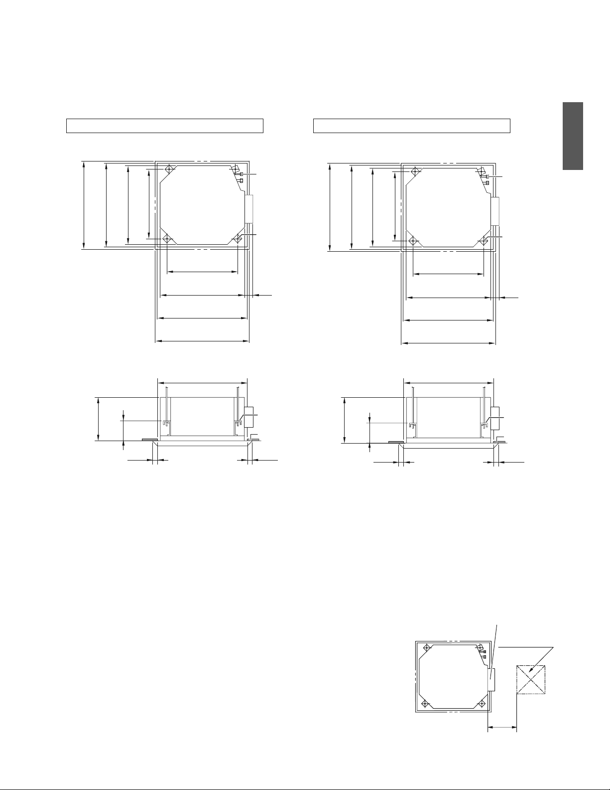
6ŶFrançais
Installation de l’unité intérieure
1. Lien entre l’ouverture au plafond et l’unité, et positionnement du boulon
de suspension
Vue de dessus
Vue de côté
Tuyauterie de
réfrigérant
Boulon de
suspension
(×4)
Faux plafond
7-1/16
(180)
ű
*
13/16
(20)
ű
*
13/16
(20)
2-1/2
(63)
27-9/16 (700)
Panneau de décoration
22-5/8 (575)
Unité intérieure
21 (533)
Pas de boulon de suspension
23-1/16-26 (585-660)
Ouverture au plafond
23-1/16-26 (585-660)
Ouverture au plafond
27-9/16 (700)
Panneau de décoration
23-1/16-26 (585-660)
Ouverture au plafond
22-5/8 (575)
Unité intérieure
21 (533)
Pas de boulon de suspension
Support de
suspension
Tuyauterie de
réfrigérant
Boulon de
suspension
(×4)
24-7/16 (620)
Panneau de décoration
7-1/2
(190)
23-1/16-23-7/16 (585-595)
Ouverture au plafond
22-5/8 (575)
Unité intérieure
24-7/16 (620)
Panneau de décoration
23-1/16-23-7/16 (585-595)
Ouverture au plafond
ű
*
1/2
(12,5)
ű
*
1/2
(12,5)
22-5/8 (575)
Unité intérieure
2-1/2
(63)
21 (533)
Pas de boulon de suspension
Faux plafond
23-1/16-23-7/16 (585-595)
Ouverture au plafond
21 (533)
Pas de boulon de suspension
Vue de dessus
Vue de côté
unité : inch (mm)
Pour panneau de décoration de type B
Pour panneau de décoration de type A
Support de
suspension
11-3/4
(298)
11-1/4
(285)
REMARQUE
r *Si le panneau ne se prolonge pas au delà du plafond, complétez avec du matériel de plafond supplémentaire ou restaurez le
plafond.
r +PUVCNNG\NoQWXGTVWTGFoKPURGEVKQPUWTNGEQVÅFWDQÊVKGTFGE¾DNCIGÅNGEVTKSWGECTKNUoCIKVFoWPRQKPVFoQÕNoGPVTGVKGPGVNoKPURGEVKQP
FWDQÊVKGTFGE¾DNCIGÅNGEVTKSWGGVFGNCRQORGFoÅXCEWCVKQPUQPVHCEKNGU
Ouverture
d’inspection
Boîtier de câblage électrique
11-3/4
(300)
17-11/16×17-11/16
(450×450)
Français
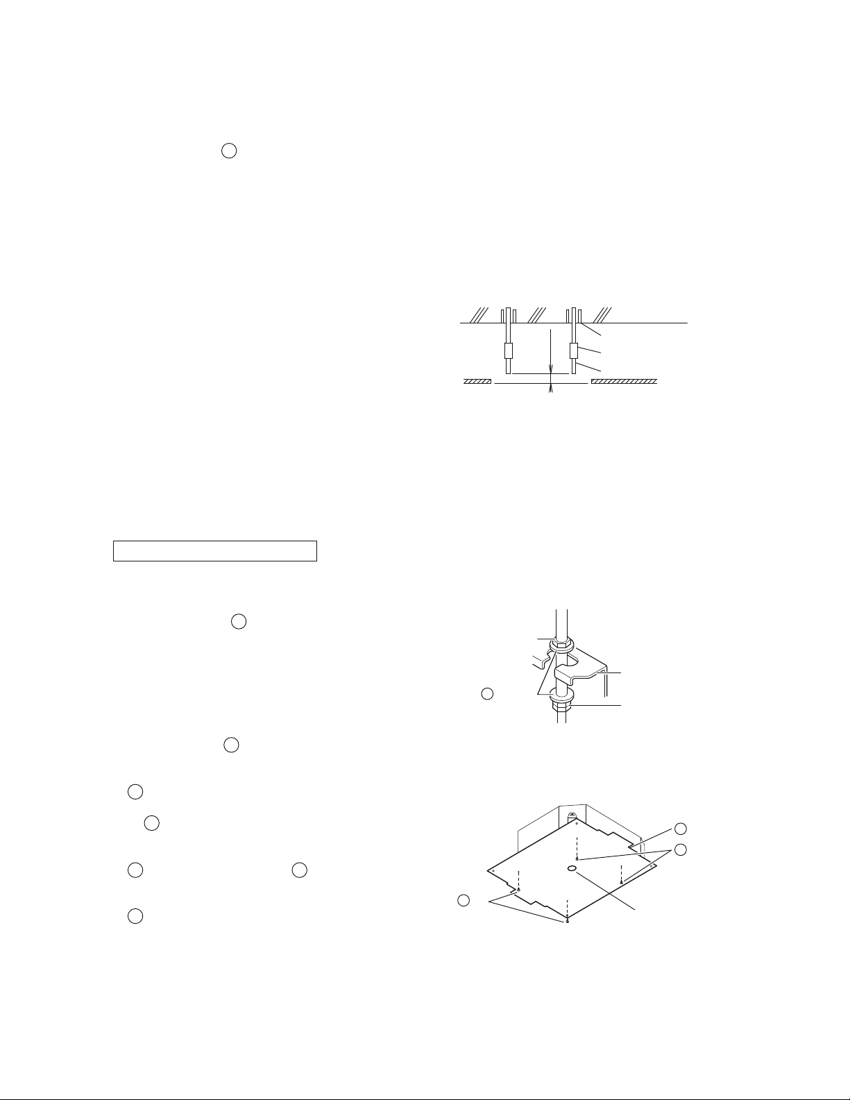
7 ŶFrançais
Installation de l’unité intérieure
2. Le cas échéant, faire l’ouverture au plafond nécessaire pour l’installation
(Pour les plafonds existants)
r Reportez-vous au
'
modèle pour les dimensions d’ouverture au plafond.
r %TÅGTNoQWXGTVWTGCWRNCHQPFTGSWKUGRQWTNoKPUVCNNCVKQP&WEÐVÅFGNoQWXGTVWTGXGTUNCUQTVKGFWDQÊVKGTOGVVTGGPyWXTG
NGTÅHTKIÅTCPVNGVW[CWFoÅXCEWCVKQPNGE¾DNCIGRQWTNGFKURQUKVKHFGVÅNÅEQOOCPFGPÅEGUUCKTGRQWTNGV[RGUCPUƂNGVNG
E¾DNCIGGPVTGNGUWPKVÅU4GRQTVG\XQWU¼NCUGEVKQP6W[CWFoÅXCEWCVKQPQW¼NCUGEVKQP%¾DNCIG
r #RTÄUCXQKTHCKVWPGQWXGTVWTGFCPUNGRNCHQPFKNRGWVÆVTGPÅEGUUCKTGFGTGPHQTEGTNGURQWVTGUCƂPFGOCKPVGPKTNGPKXGCW
FWRNCHQPFGVFGNoGORÆEJGTFGXKDTGT%QPUWNVG\NGEQPUVTWEVGWTRQWTRNWUFGFÅVCKNU
3. Installation des boulons de suspension
7VKNKUG\WPDQWNQPFGVCKNNG//QWNoÅSWKXCNGPV
Utilisez un trou d’ancrage pour les plafonds existants ou,
pour les nouveaux plafonds, un insert creux, un ancrage
ETGWZQWWPCWVTGÅNÅOGPVPQPHQWTPKCƂPFGTGPHQTEGTNG
plafond et de l’aider à supporter le poids de l’unité.
Ajustez le dégagement du plafond (2-4 inch (50-100mm))
avant de poursuivre.
r Les pièces ci-dessus sont non fournies.
2-4
(50-100)
unité: inch (mm)
Ancre
Plancher de plafond
Exemple d’installation
Écrou long ou tendeur
Boulon de suspension
Faux plafond
4. Installation de l’unité intérieure
Lors de l’installation des accessoires optionnels (sauf pour le panneau de décoration), lisez également le manuel
d’installation des accessoires optionnels. En fonction des conditions, il peut être plus facile d’installer les
accessoires optionnels avant l’unité intérieure. Cependant, pour les plafonds existants, toujours installer le kit
d’admission d’air frais avant d’installer l’unité.
Concernant les pièces à utiliser pour les travaux d’installation, assurez-vous de toujours utiliser les accessoires fournis et
NGURKÄEGUURÅEKƂSWGUFÅUKIPÅURCT&CKMKP
Pour les nouveaux plafonds
1) Installation temporaire de l’unité intérieure.
r (KZG\NGUWRRQTVFGUWURGPUKQPUWTNGDQWNQPFG
UWURGPUKQP#UUWTG\XQWUFGNGƂZGTUQNKFGOGPV¼NoCKFG
d’un écrou et d’une
C
rondelle placés dans les parties
supérieures et inférieures du support de suspension.
Support de suspension
Double écrou
(non fourni, serrer)
Écrou
(non fourni)
Rondelle
C
Fixation du support de suspension
2) Reportez-vous au
'
modèle pour les dimensions d’ouverture au plafond.
Consultez le constructeur ou le charpentier pour plus de détails.
r Le centre de l’ouverture au plafond est indiqué sur le
'
modèle. Cette indication montre également le centre de
l’unité.
r Le
'
OQFÄNGRGWVÆVTGRKXQVÅFGCƂPFoKPFKSWGTNGU
dimensions correctes sur les 4 côtés.
r #RTÄUCXQKTFÅEQWRÅNGOQFÄNGFGNoGODCNNCIGƂZG\NG
'
modèle sur l’unité avec des
F
vis (×4) comme le
montre le plan.
r La hauteur de plafond est indiquée sur le côté du
'
modèle. Réglez la hauteur de l’unité en fonction de
cette indication.
Installation du modèle
Modèle
E
Vis
F
VisF
Centre de l’ouverture au
plafond
Travaux de plafond
3) #LWUVG\NCRQUKVKQPFGNoWPKVÅCƂPFGDKGPNoKPUVCNNGT
(Reportez-vous à 1. Lien entre l’ouverture au plafond et l’unité, et positionnement du boulon de suspension.)
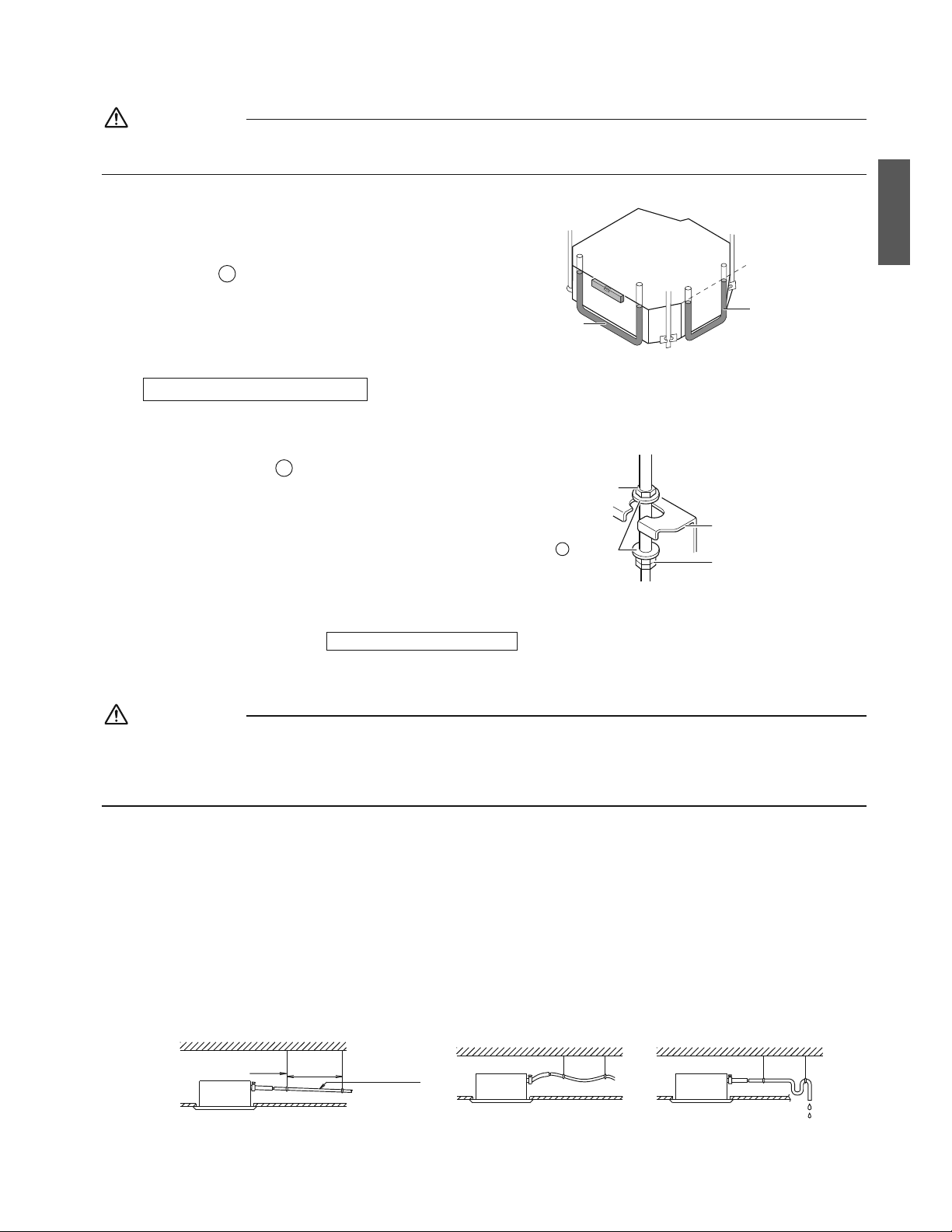
8ŶFrançais
ATTENTION
5KNoCRRCTGKNGUVKPENKPÅEQPVTGNoÅEQWNGOGPVFWEQPFGPUCVNoKPVGTTWRVGWT¼ƃQVVGWTRGWVOCNHQPEVKQPPGTGVNoGCWTKUSWGFG
pénétrer.
4) 8ÅTKƂG\SWGNoWPKVÅUQKV¼NoJQTK\QPVCNG
r L’unité intérieure est équipée d’une pompe d’évacuation
KPVÅITÅGGVFoWPEQOOWVCVGWT¼ƃQVVGWT8ÅTKƂG\
NoJQTK\QPVCNKVÅGPWVKNKUCPVWPPKXGCWQWWPVWDGFGXKP[NG
rempli d’eau.
5) Retirez le
'
modèle.
Niveau d’eau
Tube de vinyle
Tube de
vinyle
Maintenir l’horizontalité
Pour les plafonds existants
1) Installation temporaire de l’unité intérieure.
r (KZG\NGUWRRQTVFGUWURGPUKQPUWTNGDQWNQPFG
suspension. Assurez-vous de le fixer solidement à l’aide
d’un écrou et d’une
C
rondelle, placés dans les parties
supérieures et inférieures du support de suspension.
Support de suspension
Double écrou
(non fourni, serrer)
Écrou
(non fourni)
Rondelle
C
Fixation du support de suspension
2) Ajustez la hauteur et la position de l’unité.
(Reportez-vous à 1. Lien entre l’ouverture au plafond et l’unité, et positionnement du boulon de suspension.)
3) 'HHGEVWGTNGUÅVCRGUFCPU
Pour les nouveaux plafonds
.
5. Travail de la tuyauterie d’évacuation
ATTENTION
r .oCEEWOWNCVKQPFoGCWFCPUNGVW[CWFGRWTIGRGWVGPVTCÊPGTUQPQDUVTWEVKQP
r
Ne pas raccorder le tuyau d’évacuation aux canalisations d’eaux usées qui sentent l’ammoniac. L’ammoniac présent
dans les eaux usées peut entrer dans l’unité intérieure via les tuyaux d’évacuation, et corroder l’échangeur de chaleur.
r Gardez à l’esprit que le tuyau d’évacuation se bloque lorsque l’eau s’y accumule.
1. Installer un tuyau d’évacuation
r +PUVCNNG\NGVW[CWFoÅXCEWCVKQPVGNSWoKPFKSWÅUWTNGRNCPGVRTGPG\FGUOGUWTGUEQPVTGNCEQPFGPUCVKQP7PVW[CWOCN
WVKNKUÅRGWVGPIGPFTGTFGUHWKVGUGVÅXGPVWGNNGOGPVGPFQOOCIGTFGUOGWDNGUGVFGUDKGPU
r )CTFG\NCVW[CWVGTKGCWUUKEQWTVGSWGRQUUKDNGGVKPENKPG\N¼XGTUNGDCUCXGEWPITCFKGPVFoCWOQKPUFGUQTVG
SWGNoCKTPGRWKUUGRCUTGUVGTDNQSWżNoKPVÅTKGWTFWVW[CW
r )CTFG\NCVCKNNGFWVW[CWÅICNGQWUWRÅTKGWTG¼EGNNGFWVW[CWFGEQPPGZKQPVW[CWFGXKP[NGFGFKCOÄVTGPQOKPCN
13/16 inch (20mm) et de diamètre extérieur de 1 inch (26mm)).
r 2QWUUG\NGVW[CWFoÅXCEWCVKQPHQWTPKCWUUKNQKPSWGRQUUKDNGFCPUNCRTKUGFoÅXCEWCVKQP
r 5oKNGUVKORQUUKDNGFoKPENKPGTNGVW[CWFoÅXCEWCVKQPUWHƂUCOOGPVTGHGTG\XQWU¼“Précautions à prendre pour
vidanger la tuyauterie”.
r 2QWTRTÅUGTXGTNGVW[CWFoÅXCEWCVKQPFGNoCHHCKUUGOGPVRNCEG\NGUUWRRQTVUFGUWURGPUKQPVQWUNGU-60 inch
(1000-1500mm).
Gradient de
1/100 ou plus
Support de
suspension
CORRECT
40-60 inch
(1000-1500mm)
INCORRECT INCORRECT
Français
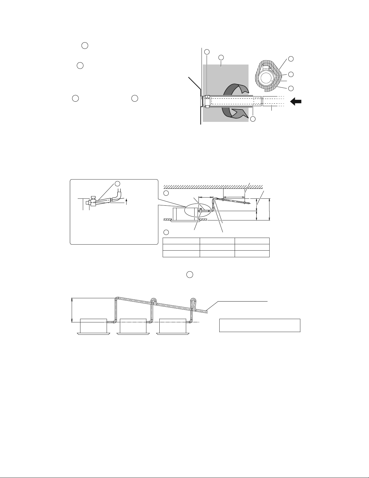
9 ŶFrançais
Installation de l’unité intérieure
r Serrez la
B
pince métallique tel qu’indiqué dans
l’illustration.
r .QTUSWGNGVGUVFGNCVW[CWVGTKGFGXKFCPIGGUVVGTOKPÅ
ƂZG\NG
J
coussinet d’étanchéité (grand) fourni
avec l’appareil, sur la partie non couverte de la prise
FoÅXCEWCVKQPGPVTGNGVW[CWFoÅXCEWCVKQPGVNGEQTRU
de l’unité).
r 'PTQWNG\NGITQUEQWUUKPGVFoÅVCPEJÅKVÅHQWTPKCWVQWT
de la
B
pince métallique et du
A
VW[CWFoÅXCEWCVKQP
RQWTNoKUQNGTGVƂZG\NGCXGEFGURKPEGU
r +UQNGTNCVQVCNKVÅFWVW[CWFoÅXCEWCVKQP¼NoKPVÅTKGWTFW
D¾VKOGPVPQPHQWTPK
r 5oKNGUVKORQUUKDNGFoKPENKPGTNGVW[CWFoÅXCEWCVKQP
UWHƂUCOOGPVCLWUVG\NGCXGEWPVW[CWFGRWTIGPQP
fourni).
Pince métalliqueB
Pince métalliqueB
Coussinet
d’étanchéité
(grand)
J
J
Prise d’évacuation
Prise d’évacuation
Tuyau d’évacuation (non fourni)
Tuyau
d’évacuation
A
Tuyau d’évacuationA
Vue A
A
Coussinet d’étanchéité
(grand)
Précautions à prendre pour vidanger la tuyauterie
r +PUVCNNG\NGUVW[CWZFoÅNÅXCVKQPFoÅXCEWCVKQP¼WPGJCWVGWTKPHÅTKGWTG¼*
r +PUVCNNG\NGUVW[CWZFoÅNÅXCVKQPFoÅXCEWCVKQPGPCPINGFTQKVRCTTCRRQTV¼NoWPKVÅKPVÅTKGWTGGV¼KPEJOO
maximum, de l’unité.
Réglable
Plancher de plafond
Ű11-3/4
(300)
40-60
(1000-1500)
unité : inch (mm)
Support de suspension
33-7/16
(850)
H2H1
Niveau ou
inclinaison
légèrement
trop élevé
Pour éviter les bulles d’air dans le tuyau
d’évacuation, gardez le en position
horizontale ou légèrement incliné. Les bulles
contenues dans le tuyau pourraient provoquer
du bruit, en raison du refoulement lors de
l’arrêt de la pompe d’évacuation.
Pince métalliqueB
Tuyau
d’évacuation
A
Tuyau d’évacuationA
Tuyau d’élévation d’évacuation
Section levée
Panneau de décoration
H1 H2
Type A 8-1/16 (205) Ű25-3/8 (645)
Type B 8-11/16 (220) Ű24-13/16 (630)
r #ƂPFGICTCPVKTNoCDUGPEGFGRTGUUKQPGZEGUUKXGUWTNG
A
VW[CWFoÅXCEWCVKQPPGLCOCKURNKGTQWVQTFTGNGVW[CWNQTU
de l’installation car cela pourrait provoquer des fuites.
r 5KRNWUKGWTUVW[CWZFoÅXCEWCVKQPUEQPXGTIGPVKPUVCNNG\UGNQPNGOQFGQRÅTCVQKTGKPFKSWÅEKFGUUQWU
Tuyau central d’évacuation
0–25-3/8 inch
(0-645mm)
Le tuyau d’évacuation devrait être
incliné d’au moins 1/100 pour éviter la
formation de poches d’air.
L’accumulation d’eau dans le tuyau
d’évacuation peut entraîner son obstruction.
5ÅNGEVKQPPGTFGUVW[CWZFoÅXCEWCVKQPEQPXGTIGPVUCXGEFGULCWIGUGUVCFCRVżNCECRCEKVÅFGHQPEVKQPPGOGPVFG
l’unité.
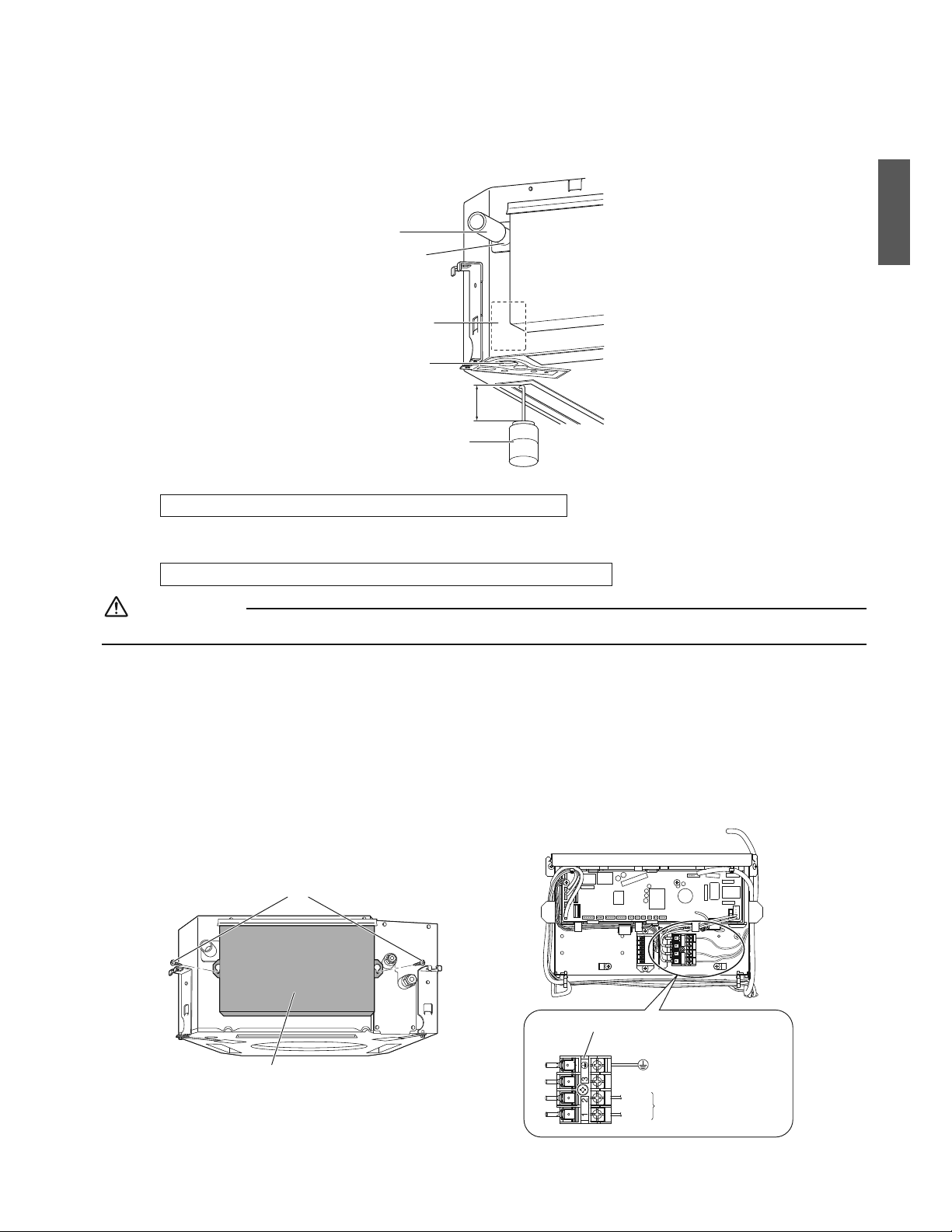
10ŶFrançais
.QTUSWGNGUVTCXCWZFGVW[CWVGTKGUQPVVGTOKPÅUXÅTKƂG\UKNCRWTIGGUVƃWKFG
r #LQWVG\NGPVGOGPVICNFoGCWGPXKTQPFGRWKUNCUQTVKGFoCKTGVXÅTKƂG\NGFÅDKVFGNCRWTIG
unité : inch (mm)
Méthode pour ajouter de l’eau
Tuyau
d’évacuation
Prise d’évacuation
(Point de vue de
l’écoulement d’eau)
Emplacement de la
pompe d’évacuation
Récipient en plastique pour
verser
Le tuyau devrait mesurer
4 inch (100mm) environ.
Sortie d’évacuation
(avec bouchon en
caoutchouc)
Utilisez cette sortie
pour évacuer l’eau
du bac d’évacuation.
ű
(100)
Lorsque le travail de câblage électrique est terminé
r 8ÅTKƂG\NGFÅDKVFGNCRWTIGRGPFCPVNGHQPEVKQPPGOGPV4'(41+&+55GZRNKSWÅFCPU“Fonctionnement d’essai et
test” à la page 17.
Lorsque le travail de câblage électrique n’est pas terminé
ATTENTION
.GUVTCXCWZFGE¾DNCIGÅNGEVTKSWGFQKXGPVÆVTGUGHHGEVWÅURCTWPÅNGEVTKEKGPEGTVKƂÅ
r 5KNCRGTUQPPGSWKGHHGEVWGNGVTCXCKNPoCRCUNGUSWCNKƂECVKQPUTGSWKUGUGHHGEVWG\NGUCEVKQPUUWKXCPVGUNQTUSWGNG
fonctionnement d’essai est terminé.
1) 4GVKTG\NGEQWXGTENGFWDQÊVKGTFGE¾DNCIGÅNGEVTKSWGXKU2QWTNoCNKOGPVCVKQPÅNGEVTKSWGEQPPGEVG\NoCNKOGPVCVKQP
OQPQRJCUÅG/1012*#5¥*\8CWZEQPPGZKQPU0
o
1 et N
o
FWDQTPKGT
Pour l’alimentation électrique, ne pas connecter au N
o
FWDQTPKGTECTNCRQORGFoÅXCEWCVKQPPGHQPEVKQPPGTCRCU
.QTUFGUVTCXCWZFGE¾DNCIGGPTCRRQTVCXGENGDQÊVKGTFGE¾DNCIGÅNGEVTKSWGCUUWTG\XQWUSWoCWEWPFGUEQPPGEVGWTU
ne se défont.
#UUWTG\XQWUFGƂZGTNGEQWXGTENGFWDQÊVKGTFGE¾DNCIGÅNGEVTKSWGCXCPVNCOKUGUQWUVGPUKQP
2) #RTÄUEQPƂTOCVKQPFGNCRWTIGEQWRG\NoCNKOGPVCVKQPÅNGEVTKSWGGVTGVKTG\NGE¾DNGFoCNKOGPVCVKQP
3) (KZG\NGEQWXGTENGFWDQÊVKGTFGE¾DNCIGÅNGEVTKSWGEQOOGFKVRNWUVÐV
Vis
Couvercle du boîtier de câblage électrique
Sol
Bornier pour l’alimentation électrique
Alimentation monophasée
(60Hz 208/230V)
N
o
2
N
o
1
Français
11 ŶFrançais
Installation de l’unité intérieure
6. Câblage
Reportez-vous aussi au manuel d’installation de l’unité extérieure.
AVERTISSEMENT
r 0oWVKNKUG\RCUFGE¾DNGUVCTCWFÅUFGE¾DNGFGTCNNQPIGPKFGEQPPGZKQPUGPÅVQKNGECTKNURGWXGPVRTQXQSWGTWPGUWTEJCWHHG
une électrocution ou un incendie.
r 0oWVKNKUG\RCUFGRKÄEGUÅNGEVTKSWGUCEJGVÅGUNQECNGOGPVFCPUNGRTQFWKV0GDTCPEJG\RCUNoCNKOGPVCVKQPFGNCRQORG
FoÅXCEWCVKQPGVE¼RCTVKTFWDQTPKGT%GNCRQWTTCKVRTQXQSWGTWPGÅNGEVTQEWVKQPQWWPKPEGPFKG
r 0GEQPPGEVG\RCUNGE¾DNGFoCNKOGPVCVKQP¼NoWPKVÅKPVÅTKGWTG%GNCRQWTTCKVRTQXQSWGTWPGÅNGEVTQEWVKQPQWWPKPEGPFKG
ATTENTION
r .QTUFGNCEQPPGZKQPFWE¾DNGFGTCEEQTFGOGPVCWDQTPKGT¼NoCKFGFoWPƂN¼
cœur unique, assurez-vous d’effectuer un roulage.
.GURTQDNÄOGUCXGENoKPUVCNNCVKQPRGWXGPVECWUGTEJCNGWTGVKPEGPFKGU
Correct Incorrect
r 2QWTUGTTGTNGE¾DNCIGWVKNKUG\NGUQWVKNUFGUGTTCIGKPENWUCƂPFoGORÆEJGTNCRTGUUKQPGZVÅTKGWTGFGUoGZGTEGTUWTNGU
EQPPGZKQPUFGUE¾DNGURWKUUGTTGTHGTOGOGPV.QTUFWE¾DNCIGCUUWTG\XQWUSWGNGUE¾DNGUUQPVRTQRTGUGVSWoKNUPG
EQNNGPVRCUCWEQWXGTENGFWDQÊVKGTFGE¾DNCIGÅNGEVTKSWGRWKUHGTOG\NGEQWXGTENGHGTOGOGPV
r NoGZVÅTKGWTFGNoWPKVÅUÅRCTG\NGE¾DNCIGFGDCUUGVGPUKQPE¾DNCIGFGNCVÅNÅEQOOCPFGGVNGE¾DNCIGFGJCWVGVGPUKQP
E¾DNCIGGPVTGNGUWPKVÅUNCVGTTGGVFoCWVTGUE¾DNGUFoCNKOGPVCVKQPFoCWOQKPUKPFGUQTVGSWoKNUPGRCUUGPVRCURCTNG
OÆOGGPFTQKV.CRTQZKOKVÅRGWVRTQXQSWGTFGUKPVGTHÅTGPEGUÅNGEVTKSWGUFGUF[UHQPEVKQPPGOGPVUGVFGUFQOOCIGU
Couple de serrage pour les borniers
r 7VKNKUG\NGDQPVQWTPGXKURQWTUGTTGTNGUXKUFGUDQTPGU5KNCNCOGFWVQWTPGXKUGUVVTQRRGVKVGNCVÆVGFGNCXKURGWVÆVTG
endommagée, et la vis ne sera pas correctement serrée.
r 5KNGUXKUFGUDQTPGUUQPVVTQRUGTTÅGUNGUXKUTKUSWGPVFoÆVTGGPFQOOCIÅU
r 4GRQTVG\XQWUCWVCDNGCWEKFGUUQWURQWTNGEQWRNGFGUGTTCIGFGUXKUFGUDQTPGU
WPKVÅUNDHrHV0rO
Couple de serrage
Bornier pour télécommande (6P) 0,58 - 0,72 (0,79 - 0,98)
$QTPKGTRQWTE¾DNGFoCNKOGPVCVKQP2 0,87 - 1,06 (1,18 - 1,44)
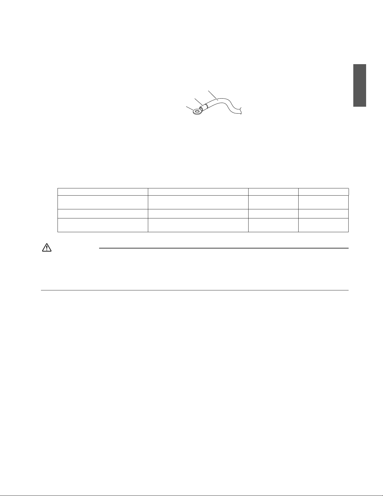
12ŶFrançais
Précautions à prendre pour le câblage d’alimentation électrique
2QWTNoCNKOGPVCVKQPÅNGEVTKSWGGVNGTCEEQTFGOGPVCWDQTPKGTWVKNKUG\WPGDQTPG¼UGTVKTTQPFG5KEGNCUoCXÄTGKORQUUKDNG¼
cause d’un cas de force majeure, assurez-vous de respecter les consignes suivantes :
r %QPEGTPCPVNGE¾DNCIGCUUWTG\XQWUSWGNGUE¾DNGUCRRTQRTKÅUUQPVWVKNKUÅUGHHGEVWG\FGUEQPPGZKQPUEQORNÄVGUGV
ƂZG\NGUE¾DNGUFGVGNNGUQTVGSWGFGUHQTEGUGZVGTPGUPGUQKGPVRCUCRRNKSWÅGUCWZDQTPGU
Manchon d’isolation
Câblage
Borne à sertir ronde
r 0oWVKNKUG\SWGFGUE¾DNGUGPEWKXTG
r 2QWTNGUVTCXCWZFGE¾DNCIGÅNGEVTKSWGTGRQTVG\XQWUÅICNGOGPVCW“diagramme de câblage” attaché au couvercle du
DQÊVKGTFGE¾DNCIGÅNGEVTKSWG
r 2QWTNGUFÅVCKNUEQPEGTPCPVNGE¾DNCIGFGNCVÅNÅEQOOCPFGTGRQTVG\XQWUCWOCPWGNFoKPUVCNNCVKQPHQWTPKCXGENC
télécommande.
r 7PFKULQPEVGWTRGTOGVVCPVFGEQWRGTNoCNKOGPVCVKQPFGNoGPUGODNGFWU[UVÄOGFQKVÆVTGKPUVCNNÅ
r 5RÅEKƂECVKQPURQWTE¾DNGT
.GE¾DNCIGFGNCVÅNÅEQOOCPFGFQKVÆVTGCEJGVÅNQECNGOGPV
6CDNGCW
%¾DNG Taille Longueur (ft.)
%¾DNCIGGPVTGNGUWPKVÅU
.CVCKNNGGVNCNQPIWGWTFWE¾DNGFQKXGPV
être conformes aux codes locaux.
––
%¾DNCIGFGNCVÅNÅEQOOCPFG )CÊPÅGƂNU #9) Max.1640*
%¾DNCIGFGNCDQTPGFGOKUG¼NC
terre
.CVCKNNGGVNCNQPIWGWTFWE¾DNGFQKXGPV
être conformes aux codes locaux.
––
+NUoCIKVFGNCNQPIWGWTVQVCNGOCZKOCNGFCPUNGU[UVÄOGNQTUSWGXQWUHCKVGUNGEQPVTÐNGFWITQWRG
ATTENTION
r &KURQUG\NGUHKNUGVHKZG\NGEQWXGTENGHGTOGOGPVCHKPSWGEGFGTPKGTPGHNQVVGRCURGPFCPVNGUVTCXCWZFGE¾DNCIG
r 0oCVVCEJG\RCUGPUGODNGNGUE¾DNGUFGNCVÅNÅEQOOCPFGGPVTGNGUWPKVÅU%GNCRQWTTCKVGPVTCÊPGTWPF[UHQPEVKQPPGOGPV
r .GUE¾DNGUFGNCVÅNÅEQOOCPFGGVNGE¾DNCIGGPVTGNGUWPKVÅUFQKVÆVTGUKVWżCWOQKPUKPEJOOFGUCWVTGUHKNU
électriques.
0GRCUUWKXTGEGVVGFKTGEVKXGRGWVGPVTCÊPGTWPF[UHQPEVKQPPGOGPVF×CWZKPVGTHÅTGPEGUÅNGEVTKSWGU
Français
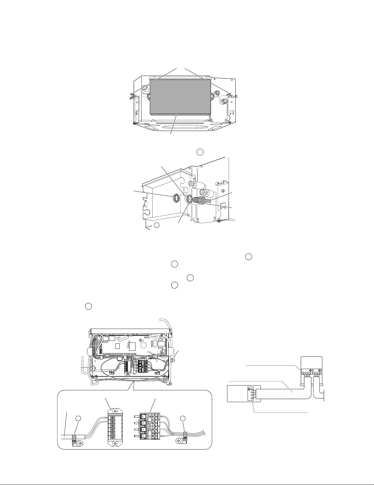
13 ŶFrançais
Installation de l’unité intérieure
4CEEQTFGOGPVFWE¾DNCIGGPVTGNGUWPKVÅUNGƂNFGVGTTGGVNGE¾DNCIGFGNCVÅNÅEQOOCPFG
%¾DNCIGGPVTGNGUWPKVÅUGVNGƂNFGVGTTG
1) 4GVKTG\NGEQWXGTENGFWDQÊVKGTFGE¾DNCIGÅNGEVTKSWGXKU
Vis
Couvercle du boîtier de câblage électrique
2) +PUÅTG\NGUE¾DNGU[EQORTKUNGƂNFGVGTTGFCPUNCEQPFWKVGGVUÅEWTKUG\NCEQPFWKVGLWUSWoCWVTQWUKVWÅFCPUNGDQÊVKGT
FGE¾DNCIGÅNGEVTKSWG¼NoCKFGFoWPÅETQWFGDNQECIGGVFGNC
N
rondelle pour conduit, comme le montre l’illustration.
Écrou de blocage
(non fourni)
Conduite
(non fourni)
Trou dans le boîtier de
câblage électrique
Rondelle pour conduit
N
Tuyau de conduite
3) %QPPGEVG\NGƂNFGVGTTGCWZDQTPGUEQTTGURQPFCPVGU
4) (CKVGUEQTTGURQPFTGNGUEQWNGWTUCXGENGUPWOÅTQUFGDQTPGUUWTNGDQTPKGTFGNoWPKVÅKPVÅTKGWTGGVGZVÅTKGWTGGVƂZG\
UQNKFGOGPVNGUE¾DNGUFCPUNGUDQTPGUEQTTGURQPFCPVGUCXGENGUXKU
5) %GHCKUCPVVKTG\NGUE¾DNGU¼NoKPVÅTKGWTFWVTQWGVƂZG\NGUGPVQWVGUÅEWTKVÅCXGENC
&
pince inclue.
6) &QPPG\UWHƂUCOOGPVFGOQWCWZE¾DNGUGPVTGNC
&
RKPEGGVNGDQTPKGTRQWTNoCNKOGPVCVKQP
7) 6KTG\NGUE¾DNGU¼VTCXGTUNoQWXGTVWTGGVEQPPGEVG\NGUCWDQTPKGTRQWTVÅNÅEQOOCPFGRCUFGRQNCTKVÅ
(KZG\UQNKFGOGPVNGE¾DNCIGFGNCVÅNÅEQOOCPFGCXGENC
&
pince inclue.
8) &QPPG\UWHƂUCOOGPVFGOQWCWZE¾DNGUGPVTGNC
&
RKPEGGVNGDQTPKGTRQWTVÅNÅEQOOCPFG
9) (KZG\NGEQWXGTENGFWDQÊVKGTFGE¾DNCIGÅNGEVTKSWGEQOOGFKVRNWUVÐV
10) .QTUSWGVQWVGUNGUEQPPGZKQPUQPVÅVÅHCKVGUEQODNG\NGUGURCEGUXKFGUFCPUNGUVTQWUFGE¾DNCIGFWDQÊVKGTCXGEFW
mastic ou le
M
EQWUUKPGVFoÅVCPEJÅKVÅRGVKVCƂPFoGORÆEJGTNGURGVKVUCPKOCWZQWNCUCNGVÅFGRÅPÅVTGTFCPUNoWPKVż
RCTVKTFGNoGZVÅTKGWTGVFGRTQXQSWGTFGUEQWTVUEKTEWKVUFCPUNCDQÊVGFGE¾DNCIGÅNGEVTKSWG
Bornier pour télécommande
Pince
D
Bornier pour l’alimentation électrique
Pince
D
Ouverture
pour câble
Câblage de la
télécommande
Conduite
123
123
L1 L
2
Fixez solidement les câbles
avec les vis de la borne.
Unité
extérieure
Unité
intérieure
Fixez solidement les câbles
avec les vis de la borne.
La taille et la longueur du
câble doivent être conformes
aux codes locaux.
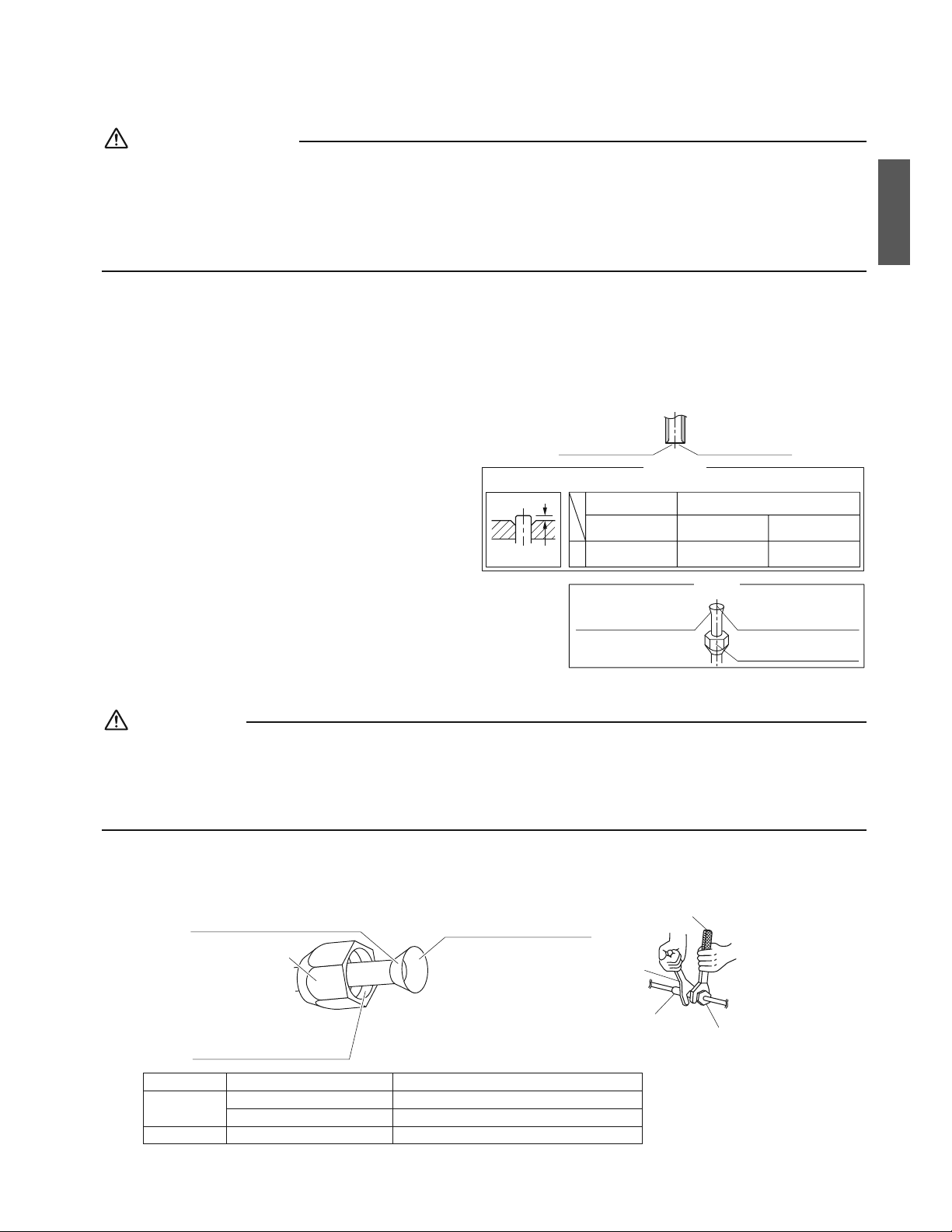
14ŶFrançais
Travaux de tuyauterie de réfrigérant
Reportez-vous aussi au manuel d’installation de l’unité extérieure.
AVERTISSEMENT
r N’appliquez pas d’huile minérale sur la partie évasée.
r ¥XKVG\SWGNoJWKNGOKPÅTCNGPGRÅPÄVTGFCPUNGU[UVÄOGECTEGNCTÅFWKTCKVNCFWTÅGFGUGTXKEGFGUWPKVÅU
r
0oWVKNKUG\LCOCKUFGVW[CWZC[CPVFÅL¼ÅVÅWVKNKUÅURQWTFGUKPUVCNNCVKQPUCPVÅTKGWTGU0oWVKNKUG\SWGNGURKÄEGUNKXTÅGUCXGENoWPKVÅ
r 0GƂZG\LCOCKUFGFÅUJWOKFKƂECVGWT¼EGVVGWPKVÅ4#CƂPFGICTCPVKTUCFWTÅGFGUGTXKEG
r .GOCVÅTKGNFGFÅUJWOKFKƂECVKQPRGWVUGFKUUQWFTGGVGPFQOOCIGTNGU[UVÄOG
r Un évasement incomplet peut entraîner une fuite de gaz réfrigérant.
Exécuter des travaux d’isolation thermique complets sur les deux côtés des tuyaux de gaz et des tuyaux de liquide. Dans
le cas contraire, une fuite d’eau peut parfois apparaître.
#UUWTG\XQWUFoWVKNKUGTFGNoKUQNCPVEQPÃWRQWTNGUU[UVÄOGU*8#%
En outre, si la température et l’humidité des tronçons de tuyaux de réfrigérant risque de dépasser 86°F (30°C) ou HR80%, renforcez
l’isolation du réfrigérant. (13/16 inch (20mm) ou plus épais) De la condensation peut se former sur la surface du matériau isolant.
#XCPVFoGHHGEVWGTFGUVTCXCWZFGVW[CWVGTKGFGTÅHTKIÅTCPVXÅTKƂG\SWGNV[RGFGTÅHTKIÅTCPVGUVWVKNKUÅ7PDQP
fonctionnement est impossible si les types de réfrigérants ne sont pas les mêmes.
1. Évasement de l’extrémité du
tuyau
1) %QWRG\NoGZVTÅOKVÅFWVW[CWCXGEWPEQWRGVW[CW
2) 'PNGXG\NGUDCXWTGUFGNCUWTHCEGFGEQWRGXGTUNG
DCUCƂPSWGNGUNKOCKNNGUPGRÅPÄVTGPVRCUFCPUNG
VW[CW
3) /GVVG\NoÅETQWÅXCUÅUWTNGVW[CW
4) ¥XCUG\NGVW[CW
5) 8ÅTKƂG\SWGNoÅXCUGOGPVCÅVÅTÅCNKUÅEQTTGEVGOGPV
A
A
Coupez exactement
à angle droit.
Enlevez les bavures.
Évasement
Placez exactement à la position indiquée ci-dessous.
Die
0-0,020 inch
(0-0,5mm)
À griffe
Outil à évaser
pour R410A
0,039-0,059 inch
(1,0-1,5mm)
À griffe
(Type rigide)
0,059-0,079 inch
(1,5-2,0mm)
À écrou à oreilles
(Type impérial)
Outil à évaser conventionnel
La surface intérieure de
l’évasement doit être
sans défaut.
L’extrémité du tuyau doit
être évasée uniformément
dans un cercle parfait.
Assurez-vous que l’écrou
évasé soit monté.
8ÅTKƂG\
2. Tuyauterie de réfrigérant
ATTENTION
r
Utilisez l’écrou évasé fixé à l’unité principale. (Pour éviter que l’écrou évasé ne se fissure suite à une détérioration au fil du temps.)
r Pour éviter les fuites de gaz, appliquez de l’huile réfrigérante uniquement sur la surface intérieure de l’évasement. (Utilisez
de l’huile réfrigérante pour R410A.)
r 7VKNKUG\WPGENÅF[PCOQOÅVTKSWGRQWTUGTTGTNGUÅETQWUÅXCUÅUCHKPFoÅXKVGTFoGPFQOOCIGTNGUÅETQWUÅXCUÅUGVFGRTÅXGPKT
les fuites de gaz.
r Alignez les centres des deux évasements et serrez à la main les écrous évasés de 3 ou 4 tours, puis serrez les à fond
CXGEWPGVTKEQKUGGVWPGENÅF[PCOQOÅVTKSWG
Ne pas appliquez d’huile réfrigérante
sur la surface extérieure.
Écrou évasé
Appliquez de l’huile réfrigérante
uniquement à la surface
intérieure de l’évasement.
Ne pas appliquer d’huile
réfrigérante à l’écrou évasé pour
éviter le serrage avec un couple
excessif.
Appliquez de l’huile
Clé
dynamométrique
Lot de tuyaux
Écrou évasé
Tricoise
Serrez
6CKNNGFGNCVW[CWVGTKG Couple de serrage de l’écrou évasé
Côté gaz
&'KPEJOO s+DHrHV0rO
&'KPEJOO s+DHrHV0rO
Côté liquide &'KPEJOO s+DHrHV0rO
Français

15 ŶFrançais
Travaux de tuyauterie de réfrigérant
Précautions relatives à la manipulation de la tuyauterie
r 2TQVÅIG\NoGZVTÅOKVÅQWXGTVGFWVW[CWFGNCRQWUUKÄTGGVNoJWOKFKVÅ
r 6QWVGUNGUEQWTDWTGUFGVW[CWFQKXGPVÆVTGCWUUKNÅIÄTGUSWGRQUUKDNG
7VKNKUG\WPGEKPVTGWUGFGVW[CWZRQWTNCEQWTDWTG
Paroi
Si aucun embout évasé
n’est disponible, couvrez
la bouche évasée avec
du ruban adhésif pour
garder la saleté et l’eau
à l’extérieur.
Pluie
Assurez-vous de
placer un embout.
Sélection des matériaux d’isolation thermique et en cuivre
.QTUFGNoWVKNKUCVKQPFGUVW[CWZGVFGUTCEEQTFUGPEWKXTGFWEQOOGTEG
respectez les consignes suivantes :
r /CVÅTKCWZFoKUQNCVKQP/QWUUGFGRQN[ÅVJ[NÄPG
6CWZFoÅEJCPIGVJGTOKSWG¼9O-¼$VWHVJ(
¼MECNOJ%
#UUWTG\XQWUFoWVKNKUGTWPGKUQNCVKQPEQPÃWGRQWTNGUU[UVÄOGU%8%
r 6W[CWGPEWKXTG#%4WPKSWGOGPV
Tuyau de gaz
Tuyau de liquide
Isolation du
tuyau de gaz
Isolation du
tuyau de liquide
4WDCPFGƂPKVKQP
Tuyau d’évacuation
r 8GKNNG\¼KUQNGT¼NCHQKUNGUVW[CWZFGIC\GVFGNKSWKFGGV¼QDUGTXGTNGUFKOGPUKQPUFoKUQNCVKQPEQOOGEKFGUUQWU
Taille de la
VW[CWVGTKG
4C[QPFGEQWTDWTG
minimum
Épaisseur de la
VW[CWVGTKG
Taille de l’isolation
thermique
Épaisseur de
l’isolation thermique
Côté gaz
&'KPEJ
(9,5mm)
1-3/16 inch (30mm)
ou plus
0,031 inch (0,8mm)
(C1220T-O)
&+KPEJ
(12-15mm)
13/32 inch (10mm)
Min.
&'KPEJ
(12,7mm)
1-9/16 inch (40mm)
ou plus
&+KPEJ
(14-16mm)
Côté liquide
&'KPEJ
(6,4mm)
1-3/16 inch (30mm)
ou plus
&+KPEJ
(8-10mm)
r 7VKNKUG\FGUVW[CWZFoKUQNCVKQPVJGTOKSWGUÅRCTÅURQWTNGUVW[CWZFGIC\GVFGNKSWKFGTÅHTKIÅTCPV
r #RTÄUCXQKTXÅTKƂÅSWoKNPo[CRCUFGHWKVGFGIC\CUUWTG\XQWUKORÅTCVKXGOGPVFoGHHGEVWGTNGUVTCXCWZFoKUQNCVKQP
VJGTOKSWGUWTNCUGEVKQPFGVW[CWFGTCEEQTFGOGPVGPÅVWFKCPVOKPWVKGWUGOGPVNGUFGUUKPUUWKXCPVUGVGPWVKNKUCPVNG
G
raccord d’isolation et le
H
raccord d’isolation des matériaux d’isolation thermique fournis. Fixer les deux extrémités
avec les
&
pinces.
Procédure d’isolation de la tuyauterie
Tuyauterie de gaz Tuyauterie de liquide
Pinces
(Utilisez 2 pinces par isolation)
D
Moyen 1 coussinet d’étanchéité pour
tuyauterie de gaz
K Moyen 2 coussinet d’étanchéité pour
tuyauterie de liquide
L
Raccord d’isolation
(Pour tuyau de liquide)
HRaccord d’isolation
(pour tuyau de gaz)
G
Tuyauterie
de gaz
Unité
principale
Fixer à la base
Connexion écrou
évasé
Pinces
(Utilisez 2 pinces par isolation)
D
Tuyauterie
de liquide
Unité
principale
Fixer à la base
Connexion écrou
évasé
Enveloppez à partir de la base de l’unité jusqu’à la
partie supérieure de la connexion d’écrou évasé
Enveloppez à partir de la base de l’unité jusqu’à la
partie supérieure de la connexion d’écrou évasé
Tuyau de gaz
Tuyau de liquide
Pinces (Utilisez 2 pinces par isolation)D
Raccord d’isolation
(Pour tuyau de liquide)
H
Raccord d’isolation
(pour tuyau de gaz)
G
ATTENTION
8GKNNG\¼KUQNGTNoGPUGODNGFGNCVW[CWVGTKGLWUSWo¼UQPRQKPVFGEQPPGZKQP¼NoKPVÅTKGWTFGNoWPKVÅ6QWVGRCTVKGGZRQUÅGFGNC
VW[CWVGTKGRGWVRTQXQSWGTFGNCEQPFGPUCVKQPQWFGUDT×NWTGUGPECUFGEQPVCEV
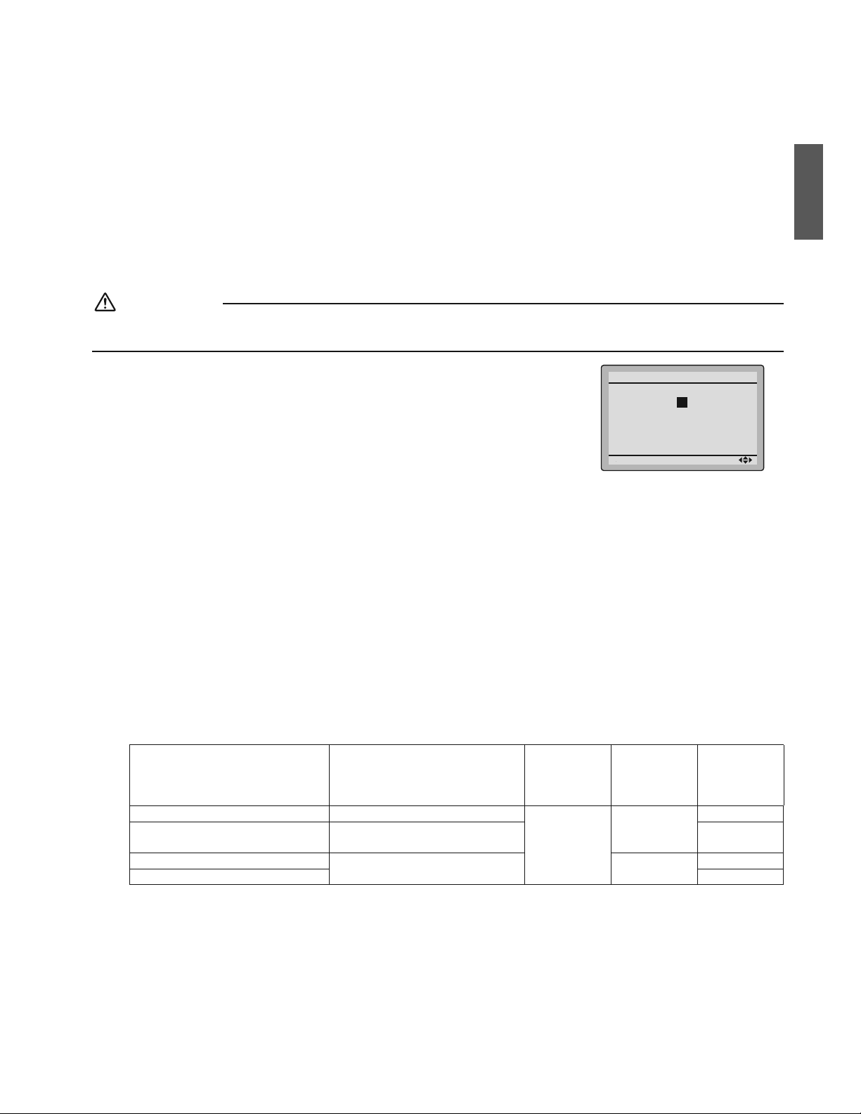
16ŶFrançais
Installation du Panneau de Décoration
#XGENCVÅNÅEQOOCPFGUCPUƂNNGTÅINCIGFWEJCORGVNGHQPEVKQPPGOGPVFoGUUCKPGRGWXGPVÆVTGUGHHGEVWÅUUCPU[
attacher le panneau de décoration.
Lire “fonctionnement d’essai et test”CXCPVFoGHHGEVWGTWPHQPEVKQPPGOGPVFoGUUCKUCPUƂZGTNGRCPPGCWFGFÅEQTCVKQP
Reportez-vous au manuel d’installation joint au panneau de décoration.
#RTÄUCXQKTKPUVCNNÅNGRCPPGCWFGFÅEQTCVKQPCUUWTG\XQWUSWoKNPo[CKVRCUFoGURCEGGPVTGNGEQTRUFGNoWPKVÅGVNGRCPPGCWFG
décoration.
Paramètres de champ
ATTENTION
Lorsque vous effectuez le paramétrage de champ ou le fonctionnement d’essai sans fixer le panneau de décoration, ne
touchez pas la pompe d’évacuation. Cela pourrait provoquer une électrocution.
r Assurez-vous que le couvercle du boîtier de câblage électrique est bien fermé, sur
les unités intérieures et extérieures.
r Les paramètres des champs doivent être effectués à partir de la télécommande et en
fonction des conditions d’installation.
r Le paramétrage peut être effectué en changeant le “Mode N
o
qp24'/+'4%1&'0
o
” et
p5'%10&%1&'0
o
”.
r Les “Paramètres de champ” inclus dans la télécommande, répertorient l’ordre des
paramètres et le mode de fonctionnement.
Unit No
0
1
–
01
5
–––
9
–––
13
–––
2
–
02
6
–––
10
–––
14
–––
3
–
01
7
–––
11
–––
15
–––
Field Settings
0
–
01
4
–––
8
–––
12
–––
Setting
Mode
20
1. Réglage de la direction de sortie d’air
r 2QWTEJCPIGTNCFKTGEVKQPFGNCUQTVKGFoCKTQWFKTGEVKQPUTGRQTVG\XQWUCWOCPWGNFoKPUVCNNCVKQPHQWTPKCXGENGMKVFG
EQWUUKPGVDNQSWCPVXGPFWUÅRCTÅOGPVQWCWOCPWGNFoGPVTGVKGP
5'%10&%1&'0
o
GUVEQPƂIWTÅRCTFÅHCWVUWTpqRQWTUQTVKGFoCKTFCPUNGUFKTGEVKQPU
2. Réglage des options
r 2QWTNCEQPƂIWTCVKQPFGUQRVKQPUTGRQTVG\XQWUCWOCPWGNFoKPUVCNNCVKQPHQWTPKCXGENoQRVKQP
3. 4ÅINCIGFGUKPFKEGUFWƂNVTG¼CKT
r .GUVÅNÅEQOOCPFGUUQPVÅSWKRÅGUFoKPFKEGUFGƂNVTG¼CKTGPETKUVCWZNKSWKFGUSWKKPFKSWGPVNQTUSWoKNGUVVGORUFGPGVVQ[GT
NGUƂNVTGU¼CKT
r %JCPIG\NG5'%10&%1&'0
o
en fonction de la quantité de saleté ou de poussière présente dans la salle.
5'%10&%1&'0
o
GUVEQPƂIWTÅRCTFÅHCWVUWTpqRQWTƂNVTG¼CKTEQPVCOKPCVKQPRCTNCNWOKÄTG
Réglage
&ÅNCKLWUSWo¼EGSWGNGXQ[CPV
6¥/1+0&'0'661;#)'&7
(+.64'#+4UoCNNWOG
V[RGNQPIWGXKG
Mode N
o
24'/+'4
%1&'0
o
5'%10&
%1&'0
o
Filtre à air contamination légère Approx. 2500hrs
10 (20)
0
01
Filtre à air contamination
importante
Approx. 1250hrs 02
#HƂEJCIGCNNWOÅ
–3
01
#HƂEJCIGÅVGKPV 02
.QTUFGNoWVKNKUCVKQPFGUVÅNÅEQOOCPFGUUCPUƂN
r .QTUSWGXQWUWVKNKUG\NGUVÅNÅEQOOCPFGUUCPUƂNNCEQPƂIWTCVKQPFGNoCFTGUUGFGUVÅNÅEQOOCPFGUUCPUƂNGUV
PÅEGUUCKTG4GRQTVG\XQWUCWOCPWGNFoKPUVCNNCVKQPHQWTPKCXGENCVÅNÅEQOOCPFGUCPUƂN
Français
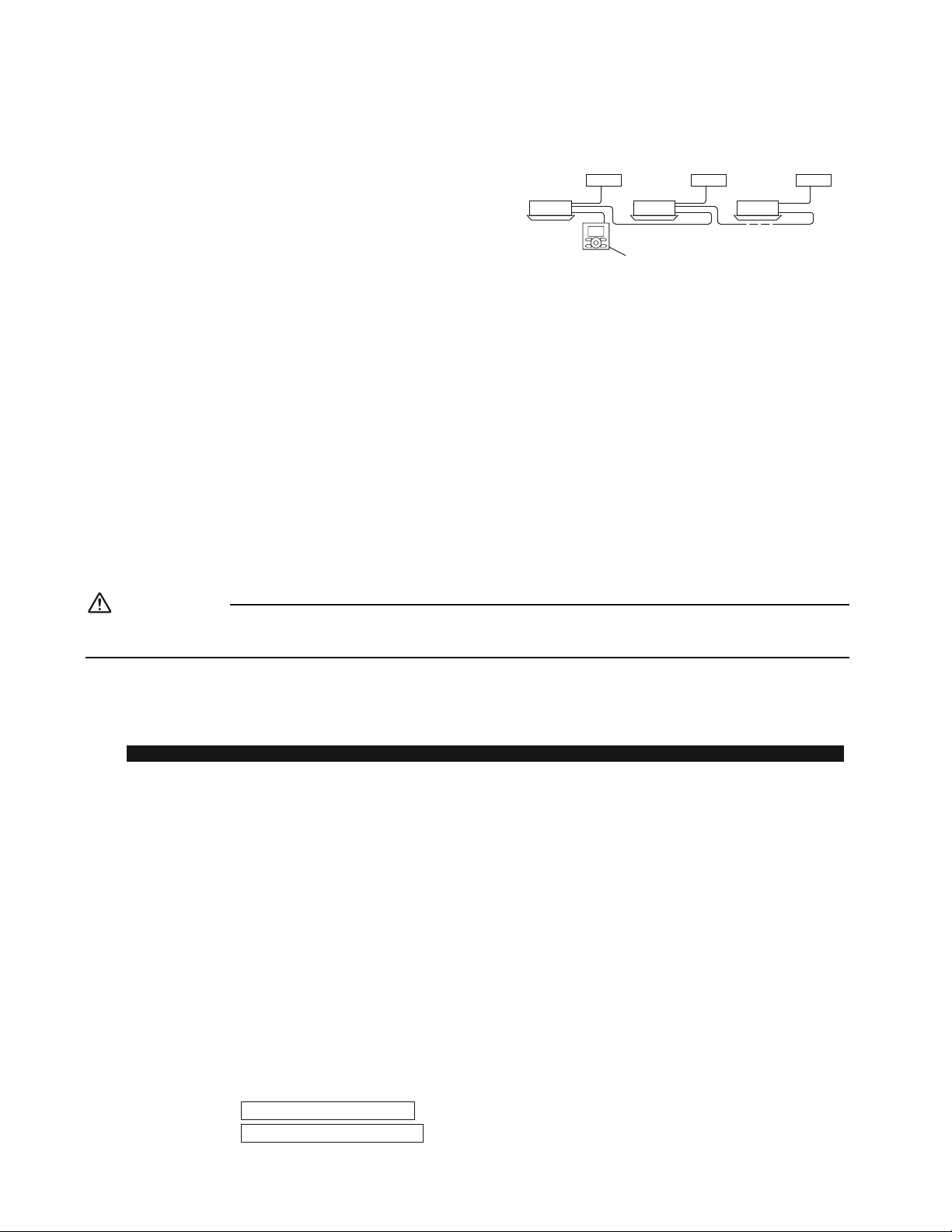
17 ŶFrançais
Paramètres de champ
4. Lors de la mise en œuvre du contrôle de groupe
r Lors de l’utilisation en tant qu’unité de paire, vous pouvez
contrôler jusqu’à 16 unités avec la télécommande.
r &CPUEGECUVQWVGUNGUWPKVÅUKPVÅTKGWTGUFWITQWRG
fonctionnent en conformité avec la télécommande de
contrôle du groupe.
r
Sélectionnez une télécommande qui correspond à autant de
HQPEVKQPUDCNCPÃQKTGTCDCVGVEFCPUNGITQWRGSWGRQUUKDNG
Unité extérieure
1
Unité extérieure
2
Unité extérieure
3
Unité intérieure 1 Unité intérieure 2
Télécommande pour le contrôle de groupe
Unité intérieure 3
Méthode de câblage (Se référer à “6. Câblage” en page 11.)
1) 4GVKTG\NGEQWXGTENGFWDQÊVKGTFGE¾DNCIGÅNGEVTKSWG
2) %¾DNCIGVTCPUXGTUCNFWDQTPKGTRQWTVÅNÅEQOOCPFG2
1, P2¼NoKPVÅTKGWTFWDQÊVKGTFGE¾DNCIGÅNGEVTKSWG+NPo[CRCUFG
polarité.)
5GTGRQTVGTCWVCDNGCWFCPU“6. Câblage” en page 12)
5. 2 télécommandes (contrôler 1 unité intérieure avec 2 télécommandes)
r Lors de l’utilisation de 2 télécommandes, l’une doit être réglée sur “MAIN” et l’autre sur “SUB”.
Méthode de câblage (Se référer à “6. Cablage” en page11.)
1) 4GVKTG\NGEQWXGTENGFWDQÊVKGTFGE¾DNCIGÅNGEVTKSWG
2)
#LQWVG\NCVÅNÅEQOOCPFGCWDQTPKGTRQWTVÅNÅEQOOCPFG22FCPUNGDQÊVKGTFGE¾DNCIGÅNGEVTKSWG+NPo[CRCUFGRQNCTKVÅ
5GTGRQTVGTCWVCDNGCWFCPU“6. Câblage” en page 12)
Fonctionnement d’essai et test
ATTENTION
.QTUSWGXQWUGHHGEVWG\NGRCTCOÅVTCIGFGEJCORQWNGHQPEVKQPPGOGPVFoGUUCKUCPUƂZGTNGRCPPGCWFGFÅEQTCVKQPPG
touchez pas la pompe d’évacuation. Cela pourrait provoquer une électrocution.
r #RTÄUCXQKTCEJGXÅNoKPUVCNNCVKQPFWVW[CWFGTÅHTKIÅTCPVFWVW[CWFoÅXCEWCVKQPGVFWE¾DNCIGÅNGEVTKSWGOGPG\WP
HQPEVKQPPGOGPVFoGUUCKCƂPFGRTQVÅIGTNoWPKVÅ
1. Fonctionnement d’essai et test
#UUWTG\XQWUFoKPUVCNNGTNGRCPPGCWFGFÅEQTCVKQPCXCPVFGRTQEÅFGT¼WPHQPEVKQPPGOGPVFoGUUCKUKNCVÅNÅEQOOCPFGUCPUƂNGUVWVKNKUÅG
r .GHQPEVKQPPGOGPVFoGUUCKFQKVÆVTGGHHGEVWÅRQWTNGUFGWZHQPEVKQPPGOGPVU4'(41+&+55'/'06QW%*#7((#)'
1-1. Mesurez la tension d’alimentation et assurez-vous qu’elle se trouve dans la plage
URÅEKƂÅG
1-2. En fonctionnement REFROIDISSEMENT, sélectionnez la température
programmable la plus basse;
en fonctionnement CHAUFFAGE, sélectionnez la température programmable la
plus élevée.
1-3. Effectuez le fonctionnement d’essai en suivant les instructions dans le manuel
FoWVKNKUCVKQPCƂPFoCUUWTGTSWGVQWVGUNGUHQPEVKQPUGVNGURKÄEGUVGNNGUSWGNG
mouvement des aérateurs, fonctionnent correctement.
r 2QWTRTQVÅIGTNGENKOCVKUGWTNGU[UVÄOGFÅUCEVKXGNGTGFÅOCTTCIGRGPFCPVOKPWVGUCRTÄUNCOKUGJQTUVGPUKQP
1-4.
Une fois le fonctionnement d’essai terminé, réglez la température à un niveau
normal (de 78°F à 82°F (de 26°C à 28°C) en fonctionnement REFROIDISSEMENT, de
68°F à 75°F (20°C à 24°C) en fonctionnement CHAUFFAGE).
r .QTUFGNoWVKNKUCVKQPFWENKOCVKUGWTGPHQPEVKQPPGOGPV4'(41+&+55'/'06GPJKXGTQWGPHQPEVKQPPGOGPV%*#7((#)'
en été, réglez-le sur le mode de fonctionnement d’essai selon la méthode suivante.
Reportez-vous à
2QWTVÅNÅEQOOCPFGƂNCKTG
à la page 18.
Reportez-vous à
2QWTVÅNÅEQOOCPFGUCPUƂN
à la page 19.
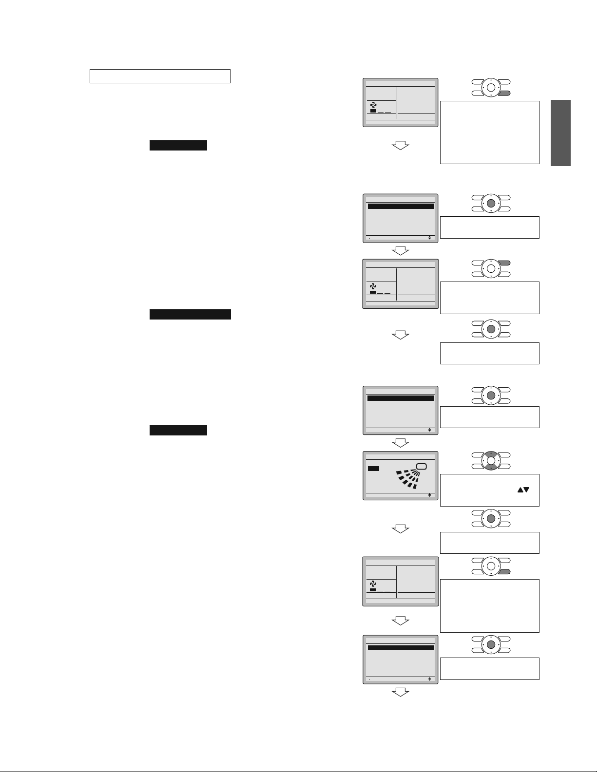
18ŶFrançais
Écran de base
1)
2)
Cool
Return %NGCPVJGƂNVGT
Set to
Cool
68F
#RRW[G\GVOCKPVGPG\
GPHQPEÅNGDQWVQP
Annuler pendant 4
secondes ou plus, tant
que le rétro-éclairage
reste allumé.
Écran du menu
des Paramètres de
service
3)
Setting
1/3
Service Settings
Test Operation
Maintenance Contact
Field Settings
Energy Saving Options
Prohibit Buttons
Min Setpoints Differential
#RRW[G\UWTNGDQWVQP
Menu/OK.
4)
5)
Set temperature
80°F
Cool
Test Operation
#RRW[G\UWTNGDQWVQP
/#4%*'#44¦6
(pendant 10 secondes).
#RRW[G\UWTNGDQWVQP
Menu/OK.
Écran du menu
principal
6)
Setting
MainMenu
Air Flow Direction
Ventilation
Schedule
Off Timer
Celsius / Fahrenheit
Maintenance Information
1/2
#RRW[G\UWTNGDQWVQP
Menu/OK.
7)
Setting
Air Flow Direction
Swing
Changez la direction du
ƃWZFoCKTGPWVKNKUCPV
NGDQWVQP*CWV$CU
#RRW[G\UWTNGDQWVQP
Menu/OK.
8)
Set temperature
80°F
Cool
Test Operation
#RRW[G\GVOCKPVGPG\
GPHQPEÅNGDQWVQP#PPWNGT
pendant 4 secondes ou
plus, tant que le rétro-
éclairage reste allumé.
9)
Setting
1/3
Service Settings
Test Operation
Maintenance Contact
Field Settings
Energy Saving Options
Prohibit Buttons
Min Setpoints Differential
#RRW[G\UWTNGDQWVQP
Menu/OK.
Écran de base
2QWTVÅNÅEQOOCPFGƂNCKTG
1) 4ÅING\UWT%11.QWHQPEVKQPPGOGPV%*#7((#)'GP
utilisant la télécommande.
2) #RRW[G\GVOCKPVGPG\GPHQPEÅNGDQWVQP#PPWNGT
pendant 4 secondes ou plus. Le menu des paramètres
FGUGTXKEGGUVCHƂEJÅ
3) Sélectionnez Test Operation dans le menu des
RCTCOÄVTGUFGUGTXKEGGVCRRW[G\UWTNGDQWVQP/GPW
1-.oÅETCPFGDCUGTÅCRRCTCÊVGVp6GUV1RGTCVKQPq
UoCHƂEJGFCPUNCRCTVKGKPHÅTKGWTG
4) #RRW[G\UWTNGDQWVQP/#4%*'#44¦6RGPFCPV
secondes, et l’opération de test commence.
Surveillez le fonctionnement de l’unité intérieure pendant
un minimum de 10 minutes. Pendant l’opération de test,
l’unité intérieure continuera à refroidir/chauffer, quelle
que soit la température de consigne et la température
CODKCPVG
r &CPUNGECUFGURTQEÅFWTGUOGPVKQPPÅGUEKFGUUWU
et 4) dans l’ordre inverse, l’opération de test peut
également commencer.
5) #RRW[G\UWTNGDQWVQP/GPW1-FCPUNoÅETCPFGDCUG
.GOGPWRTKPEKRCNGUVCHƂEJÅ
6) Sélectionnez &KTGEVKQPFWƃWZFoCKT dans le menu
RTKPEKRCNGVXÅTKƂG\SWGNCFKTGEVKQPFWƃWZFoCKTGUV
actionnée en fonction du réglage.
2QWTNGHQPEVKQPPGOGPVFWTÅINCIGFGNCFKTGEVKQPFWƃWZ
d’air, voir le manuel d’utilisation.
7) .QTUSWGNoQRÅTCVKQPFGFKTGEVKQPFWƃWZFoCKTGUV
EQPƂTOÅGCRRW[G\UWTNGDQWVQP/GPW1-.oÅETCPFG
DCUGTÅCRRCTCÊV
8) #RRW[G\GVOCKPVGPG\GPHQPEÅNGDQWVQP#PPWNGT
RGPFCPVUGEQPFGUQWRNWUFCPUNoÅETCPFGDCUG
.GOGPWFGURCTCOÄVTGUFGUGTXKEGGUVCHƂEJÅ
9) Sélectionnez Test Operation dans le menu des
RCTCOÄVTGUFGUGTXKEGGVCRRW[G\UWTNGDQWVQP/GPW
1-.oÅETCPFGDCUGTÅCRRCTCÊVGVNoQRÅTCVKQPPQTOCNGGUV
effectué.
r L’opération de test s’arrêtera automatiquement après
OKPWVGU2QWTCTTÆVGTNoQRÅTCVKQPCRRW[G\UWTNG
DQWVQP/#4%*'#44¦6
10) Si le panneau de décoration n’a pas été installé, coupez
l’alimentation après l’opération de test.
Français
19 ŶFrançais
Fonctionnement d’essai et test
2QWTVÅNÅEQOOCPFGUCPUƂN
1) #RRW[G\UWT
MODE
GVUÅNGEVKQPPG\%11.QWHQPEVKQPPGOGPV%*#7((#)'
2) #RRW[G\UWT
/TEST
FGWZHQKUp6GUVqUoCHƂEJG
3) #RRW[G\
ON OFF
dans les 10 secondes, et l’opération de test commence.
Surveillez le fonctionnement de l’unité intérieure pendant un minimum de 10 minutes. Pendant l’opération de test, l’unité
KPVÅTKGWTGEQPVKPWGTC¼TGHTQKFKTEJCWHHGTSWGNNGSWGUQKVNCVGORÅTCVWTGFGEQPUKIPGGVNCVGORÅTCVWTGCODKCPVG
r
&CPUNGECUFGURTQEÅFWTGUOGPVKQPPÅGUEKFGUUWUGVFCPUNoQTFTGKPXGTUGNoQRÅTCVKQPFGVGUVRGWVÅICNGOGPVEQOOGPEGT
r
.oQRÅTCVKQPFGVGUVUoCTTÆVGTCCWVQOCVKSWGOGPVCRTÄUOKPWVGU2QWTCTTÆVGTNGHQPEVKQPPGOGPVCRRW[G\UWT
ON OFF
.
r Certaines fonctions ne peuvent pas être utilisées dans le test de mode de fonctionnement.
Précautions à prendre
1) Reportez-vous à “3. Comment diagnostiquer des dysfonctionnements” si l’unité ne fonctionne pas correctement.
2. Éléments testés
Éléments testés 5[ORVÐOG 8ÅTKƂG\
Les unités intérieures et extérieures sont installées en
toute sécurité.
%JWVGXKDTCVKQPDTWKV
L’unité extérieure est-elle complètement installée ? #WEWPGFQOOCIGFGHQPEVKQPPGOGPVQWFGDT×NWTGU
Aucune fuite de gaz réfrigérant. Fonction refroidissement/chauffage incomplète
.GIC\TÅHTKIÅTCPVNGUVW[CWZFGNKSWKFGGVNoGZVGPUKQP
FWVW[CWFoÅXCEWCVKQPUQPVECNQTKHWIÅU
Fuite d’eau
La ligne d’évacuation est correctement installée. Fuite d’eau
.CVGPUKQPFoCNKOGPVCVKQPEQTTGURQPFGNNGDKGP¼EGNNG
indiquée sur la plaque signalétique?
#WEWPGFQOOCIGFGHQPEVKQPPGOGPVQWFGDT×NWTGU
5GWNUNGUE¾DNGUURÅEKƂÅUUQPVWVKNKUÅURQWTNGE¾DNCIG
GVVQWUNGUE¾DNGUUQPVEQTTGEVGOGPVEQPPGEVÅU
#WEWPGFQOOCIGFGHQPEVKQPPGOGPVQWFGDT×NWTGU
.GU[UVÄOGGUVEQTTGEVGOGPVOKU¼NCVGTTG Fuite électrique
.CVCKNNGFWE¾DNCIGGUVGNNGGPCEEQTFCXGENGU
URÅEKƂECVKQPU!
#WEWPGFQOOCIGFGHQPEVKQPPGOGPVQWFGDT×NWTGU
;CVKNSWGNSWGEJQUGSWKQDUVTWGNoGPVTÅGQWNCUQTVKG
d’air de l’unité intérieure ou de l’unité extérieure ?
Fonction refroidissement/chauffage incomplète
.CNQPIWGWTFWVW[CWFGTÅHTKIÅTCPVGVNCEJCTIG
additionnelle de réfrigérant sont-elles rapportées ?
.CEJCTIGFGTÅHTKIÅTCPVFCPUNGU[UVÄOGPoGUVRCU
clairement indiquée
.GUVW[CWZGVNGUE¾DNGUUQPVEQPPGEVÅUCWZRQTVUFG
EQPPGZKQPDQTPKGTUEQTTGURQPFCPVUFGNoWPKVÅEQPPGEVÅG
Pas de refroidissement/chauffage
Les clapets d’arrêt sont ouverts. Fonction refroidissement/chauffage incomplète
8ÅTKƂG\SWGNGEQPPGEVGWTFGUƂNUEQPFWEVGWTUFW
panneau de décoration est correctement connecté.
.GUHGPVGUFGXGPVKNCVKQPPGDQWIGPVRCU
L’unité intérieure reçoit correctement les informations
FGNCVÅNÅEQOOCPFGUCPUƂN
Aucun fonctionnement
¥NÅOGPVU¼XÅTKƂGTCWOQOGPVFGNCNKXTCKUQP
Consultez également les “Précautions à prendre” à la page 3
Éléments testés 8ÅTKƂG\
.GEQWXGTENGFWDQÊVKGTFGE¾DNCIGÅNGEVTKSWGNGƂNVTG¼CKTGVNCITKNNGFoCURKTCVKQPUQPVKNUDKGPƂZÅU!
Avez-vous expliqué les opérations tout en montrant le manuel d’utilisation à votre client ?
Avez-vous remis le manuel d’utilisation à votre client?
Points d’explications sur les opérations
Les éléments comprenant les mentions #8'46+55'/'06GV #66'06+10FCPUNGOCPWGNFoWVKNKUCVKQPUQPVFGUÅNÅOGPVU
TGNCVKHUCWZRQUUKDKNKVÅUFGDNGUUWTGUEQTRQTGNNGUGVFGFQOOCIGUOCVÅTKGNUNQTUFGNoWVKNKUCVKQPFWRTQFWKV2CTEQPUÅSWGPVKNGUV
nécessaire de fournir à vos clients une explication complète du contenu décrits et de leur demander de lire le manuel d’utilisation.
20ŶFrançais
Note à l’installateur
#UUWTG\XQWUFoKPUVTWKTGNGUENKGPVUUWTNGOQFGFGHQPEVKQPPGOGPVFGNoCRRCTGKNGPRCTVKEWNKGTNGPGVVQ[CIGFWƂNVTGNGHCKVFoWVKNKUGT
les différentes fonctions, et le réglage de la température), en leur faisant effectuer des opérations tout en regardant le manuel.
3. Comment diagnostiquer les dysfonctionnements
r 5KNGENKOCVKUGWTPGHQPEVKQPPGRCUPQTOCNGOGPVCRTÄUNoKPUVCNNCVKQPWPF[UHQPEVKQPPGOGPVKPFKSWÅFCPUNGVCDNGCWEKFGUUQWU
peut se produire.
#HƂEJCIGFGNCVÅNÅEQOOCPFGƂNCKTG &GUETKRVKQP
2CUFoCHƂEJCIG
r Panne de courant, voltage d’alimentation incorrect ou phase ouverte
r %¾DNCIGKPEQTTGEVGPVTGNGUWPKVÅUKPVÅTKGWTGUGVGZVÅTKGWTGU
r Circuit intérieur échec de montage
r %¾DNGFGNCVÅNÅEQOOCPFGPQPEQPPGEVÅ
r Échec de la télécommande
r (WUKDNGGPRQUKVKQPQWXGTVGQWFKULQPEVGWTFÅENGPEJÅWPKVÅGZVÅTKGWTG
p8ÅTKƂECVKQPFGNCEQPPGZKQP8GWKNNG\
patienter.” *
r Circuit intérieur échec de montage
r %¾DNCIGKPEQTTGEVGPVTGNGUWPKVÅUKPVÅTKGWTGUGVGZVÅTKGWTGU
* p8ÅTKƂECVKQPFGNCEQPPGZKQP2NGCUGUVCPFD[qTGUVGTCCHƂEJÅRGPFCPVUGEQPFGUCRTÄUNoCNNWOCIGFGNoWPKVÅKPVÅTKGWTG%GEKGUV
normal et n’est pas signe d’un mauvais fonctionnement.
&KCIPQUVKSWGTIT¾EG¼NoCHƂEJCIGFGNCVÅNÅEQOOCPFG¼CHƂEJCIG¼ETKUVCWZNKSWKFGU
#XGENCVÅNÅEQOOCPFGƂNCKTG
Lorsque l’opération s’arrête en raison d’un mauvais fonctionnement, le témoin de fonctionnement clignote et le code d’erreur
UoCHƂEJGUWTNoÅETCP¼ETKUVCWZNKSWKFGU&CPUWPVGNECUFGƂIWTGFKCIPQUVKSWG\NGEQPVGPWFGNoGTTGWTGPXQWUTÅHÅTCPV
à
'TTQT*KUVQT[ situé dans le menu des paramètres de service.
&CPUNGECUFoWPEQPVTÐNGFWITQWRGNGPFoWPKVÅUoCHƂEJGFGVGNNGUQTVGSWGNoWPKVÅKPVÅTKGWTGFÅHGEVWGWUGRWKUUGÆVTGKFGPVKƂÅG
#XGENCVÅNÅEQOOCPFGUCPUƂN
4GRQTVG\XQWUCWOCPWGNFoWVKNKUCVKQPHQWTPKCXGENCVÅNÅEQOOCPFGUCPUƂN
.QTUSWGNoQRÅTCVKQPUoCTTÆVGGPTCKUQPFoWPOCWXCKUHQPEVKQPPGOGPVNoCHƂEJCIGFGNoWPKVÅKPVÅTKGWTGUGOGV¼ENKIPQVGT&CPUWPVGN
cas, diagnostiquez les causes de l’erreur grâce au code d’erreur, en suivant les procédures suivantes.
1) #RRW[G\UWTNC617%*'+052'%6+10'55#+&'(10%6+100'/'06p
qGUVCHƂEJÅGVpqENKIPQVG
2) #RRW[G\UWTNG$17610&'4¥).#)'&'.#6'/2¥4#674'GVVTQWXG\NG0
o
de l’unité qui s’est arrêtée à cause du
RTQDNÄOG
0QODTGFGDKRU DKRUEQWTVU ..............................
DKREQWTV ..................................
DKRNQPI ...................................
'HHGEVWG\VQWVGUNGUQRÅTCVKQPUUWKXCPVGU
'HHGEVWG\GV
#WEWPRTQDNÄOG
3) #RRW[G\UWTNGDQWVQP5¥.'%6'74&'/1&'&'(10%6+100'/'06GVNGEJKHHTGUWRÅTKGWTFWEQFGFoGTTGWT
clignote.
4) %QPVKPWG\¼CRRW[GTUWTNG$17610&'4¥).#)'&'.#6'/2¥4#674'LWUSWo¼EGSWoKNHCUUGDKRUEQWTVUGV
trouvez le code supérieur.
5) #RRW[G\UWTNGDQWVQP5¥.'%6'74&'/1&'&'(10%6+100'/'06GVNGEJKHHTGKPHÅTKGWTFWEQFGFoGTTGWT
clignote.
6) %QPVKPWG\¼CRRW[GTUWTNG$17610&'4¥).#)'&'.#6'/2¥4#674'LWUSWo¼EGSWoKNHCUUGWPDKRNQPIGV
trouvez le code inférieur.
r7PDKRNQPIKPFKSWGNGEQFGFoGTTGWT
Français
1 ŶEspañol
Consideraciones de seguridad
Contenidos
Consideraciones de seguridad ..................... 1
Antes de la instalación ................................... 3
Accesorios ...................................................... 3
Selección del sitio de instalación ................. 4
Instalación de la unidad interior .................... 6
1. Relación entre la abertura de techo y la unidad y la
posición del perno de suspensión ............................... 6
2. Creación de la abertura de techo necesaria para la
instalación, si fuese aplicable
(para techos existentes) .............................................. 7
3. Instalación de los pernos de suspensión .................... 7
4. Instalación de la unidad interior ................................... 7
5. Trabajos de tubería de drenaje .................................... 8
6. Cableado ..................................................................... 11
Trabajos de tubería refrigerante .................... 14
1. Abocinamiento del extremo de tubo ............................ 14
2. Tubería refrigerante ..................................................... 14
Instalación del panel de decoración ............. 16
%QPƂIWTCEKÏPFGECORQ ................................ 16
1. Ajuste de la dirección de salida del aire ...................... 16
%QPƂIWTCEKÏPFGQREKQPGU .......................................... 16
%QPƂIWTCEKÏPFGNCUGÍCNFGNƂNVTQFGCKTG .................. 16
4. Al implementar el control de grupo .............................. 17
5. 2 controles remotos (control de 1 unidad interior
mediante 2 controles remotos) .................................... 17
Operación de ensayo y prueba ...................... 17
1. Operación de ensayo y prueba ................................... 17
2. Elementos de prueba .................................................. 19
3. Cómo diagnosticar averías .......................................... 20
Lea cuidadosamente estas Consideraciones de seguridadpara la
Instalación antes de instalar un aire acondicionado o bomba de calor.
Después de completar la instalación, asegúrese de que la unidad
funciona correctamente durante la operación de puesta en marcha.
Instruya al usuario sobre cómo operar y mantener la unidad.
Informe a los usuarios que deben almacenar este manual de
instalación con el manual de operación para futuras referencias.
Siempre use un instalador o contratista con licencia para
instalar este producto.
La instalación incorrecta puede ocasionar fugas de agua o
refrigerante, descargas eléctricas, incendios o explosiones.
5KIPKƂECFQFGNQUUÉODQNQUFGPELIGRO, ADVERTENCIA,
PRECAUCIÓN y NOTA:
PELIGRO
..........
Indica una situación inminentemente
peligrosa que, de no evitarse,
causará lesiones graves o la muerte.
ADVERTENCIA
...
Indica una situación potencialmente
peligrosa que, de no evitarse,
causará lesiones graves o la muerte.
PRECAUCIÓN
...
Indica una situación potencialmente
peligrosa que, de no evitarse, causará
lesiones menores o moderadas.
Podría usarse también para alertar
sobre las prácticas no seguras.
NOTA
.................
Indica situaciones que pueden resultar
GPFCÍQUCNGSWKRQQCEEKFGPVGUGPNC
propiedad solamente.
PELIGRO
r
El gas refrigerante es más pesado que el aire y sustituye al
oxígeno. Una fuga masiva podría causar la desaparición del
oxígeno, especialmente en sótanos, y podría causar riesgos
FGCUƂZKCTGUWNVCPVGUGPNGUKQPGUITCXGUQNCOWGTVG
r
No conecte las unidades a tierra en tuberías de agua, tubos
de gas, cables telefónicos o pararrayos, ya que una toma
a tierra incorrecta puede generar un peligro de descarga
eléctrica severa que puede ocasionar lesiones serias o la
muerte. Adicionalmente, la conexión a tierra a los tubos de gas
podría ocasionar una fuga de gas y explosiones potenciales lo
que podría ocasionar una lesión severa o la muerte.
r Si se producen fugas de gas refrigerante durante la
instalación, ventile la zona inmediatamente. El gas
refrigerante podría producir gases tóxicos al entrar en
contacto con fuego. La exposición a dichos gases puede
causar lesiones graves o la muerte.
r 7PCXG\ƂPCNK\CFCNCVCTGCFGKPUVCNCEKÏPEQORTWGDGSWG
no haya fugas de gas refrigerante al sistema.
r No instale la unidad en una zona en la que haya presente
OCVGTKCNKPƃCOCDNG[CSWGRQFTÉCPUWRQPGTWPTKGUIQFG
explosión y causar lesiones graves o la muerte.
r
Deseche de forma segura todo el material de embalaje y
de transporte en conformidad con las leyes u ordenanzas
federales, estatales o locales. El material de embalaje como
los clavos así como otras piezas de metal o madera, incluido
el material de embalaje de plástico usado para el transporte
podría ocasionar lesiones o la muerte por sofocación.
ADVERTENCIA
r
5QNCOGPVGGNRGTUQPCNEWCNKƂECFQFGDGTGCNK\CTGNVTCDCLQFG
instalación. La instalación se debe realizar en conformidad con
este manual de instalación. La instalación incorrecta puede
causar fugas de agua, descargas eléctricas o incendios.
r
#NKPUVCNCTNCWPKFCFGPJCDKVCEKQPGURGSWGÍCUVQOGOGFKFCU
para mantener la concentración de refrigerante dentro de
los límites de seguridad permisibles. Las fugas excesivas de
refrigerante, en caso de un accidente en un espacio ambiental
EGTTCFQRWGFGPQECUKQPCTNCFGƂEKGPEKCFGQZÉIGPQ
r 7UGUQNCOGPVGNQUCEEGUQTKQU[RKG\CUGURGEKƂECFQU
para el trabajo de instalación. Si no usa las piezas
GURGEKƂECFCURQFTÉCPRTGUGPVCTUGHWICUFGCIWC
descarga eléctrica, incendios o caída de la unidad.
r
Instale el aire acondicionado o la bomba de calor sobre una
DCUGNQUWƂEKGPVGOGPVGHWGTVGSWGRWGFCUQRQTVCTGNRGUQ
FGNCWPKFCF7PCDCUGSWGPQVGPICNCHWGT\CUWƂEKGPVG
puede ocasionar que se caiga la unidad y lesiones.
r
Tome en cuenta la intensidad del viento, tifones o terremotos
cuando instale la unidad. Una instalación incorrecta puede
causar que se caiga la unidad y ocasionar accidentes.
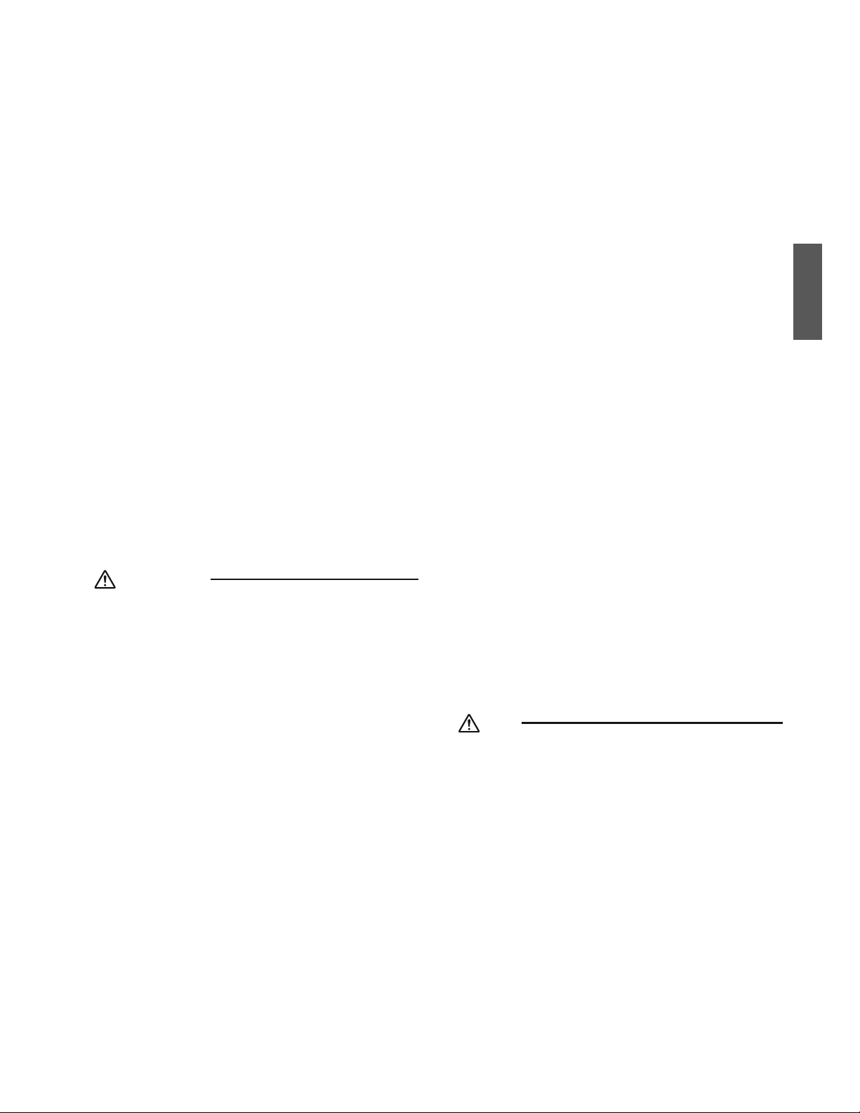
2ŶEspañol
r
Asegúrese de separar el circuito de suministro de alimentación
proporcionado para esta unidad y que todo el trabajo sea realizado
RQTRGTUQPCNECNKƂECFQGPEQPHQTOKFCFEQPNCUTGIWNCEKQPGU
locales, estatales y nacionales. La capacidad de suministro de
CNKOGPVCEKÏPKPUWƂEKGPVGQWPCEQPUVTWEEKÏPGNÅEVTKECKPEQTTGEVC
puede causar descargas eléctricas o incendios.
r
Asegúrese de que todo el cableado esté asegurado, que se
WUGPNQUECDNGUGURGEKƂECFQU[SWGNCUHWGT\CUGZVGTPCUPQ
actúen en las conexiones o cables del terminal. Las conexiones
o instalaciones incorrectas pueden ocasionar incendios.
r
Al realizar la conexión, posicione los cables de manera que
la cubierta de la caja de cableado eléctrico pueda sujetarse
de forma segura. El posicionamiento incorrecto de la cubierta
de la caja de cableado eléctrico puede ocasionar descargas
eléctricas, incendios o sobrecalentamiento de los terminales.
r Antes de tocar las piezas eléctricas, apague la unidad.
r
El circuito debe estar protegido con dispositivos de seguridad
de acuerdo a lo dispuesto en los códigos locales y nacionales, o
sea, con un fusible, un disyuntor, un desconectador o un GFCI.
r
Sujete de forma segura la cubierta de terminales de la unidad
exterior (panel). Si la cubierta de terminales/panel no se instala
correctamente, el polvo o el agua podrían ingresar a la unidad
exterior y ocasionar un incendio o descargas eléctricas.
r
Al instalar o reubicar el sistema, mantenga el circuito refrigerante
NKDTGFGUWUVCPEKCUFKUVKPVCUCNTGHTKIGTCPVGGURGEKƂECFQ4#
como por ejemplo aire. La presencia de aire o de cualquier
QVTCOCVGTKCGZVTCÍCGPGNEKTEWKVQFGNTGHTKIGTCPVGECWUCTÉCWP
aumento anormal de la presión o una ruptura y lesiones.
r
0QECODKGNCEQPƂIWTCEKÏPFGNQUFKURQUKVKXQUFGRTQVGEEKÏP
Si el interruptor de presión, el interruptor térmico u otro
dispositivo de protección tienen un cortocircuito y se operan
forzadamente, o si se usan otras piezas no genuinas de
Daikin, puede ocurrir un incendio o explosiones.
PRECAUCIÓN
r
No toque el interruptor con los dedos mojados. Tocar un interruptor
con los dedos mojados puede ocasionar una descarga eléctrica.
r 0QRGTOKVCSWGNQUPKÍQULWGIWGPEGTECQCNTGFGFQTFGNC
unidad para evitar lesiones.
r .CUCNGVCUFGNKPVGTECODKCFQTFGECNQTGUV½PCƂNCFCU
NQUWƂEKGPVGRCTCSWGEQTVGP2CTCGXKVCTNGUKQPGUWUG
guantes o cubra las aletas mientras trabaja alrededor.
r
No toque la tubería refrigerante durante y justo después del
funcionamiento ya que la tubería refrigerante podría estar caliente
QHTÉCFGRGPFKGPFQFGNCUEQPFKEKQPGUFGNTGHTKIGTCPVGSWGƃW[G
a través de la tubería refrigerante, compresor y otras piezas del
ciclo de refrigeración. Sus manos podrían sufrir quemaduras o
congelación si toca las tuberías refrigerantes. Para evitar lesiones,
permita que los tubos adquieran su temperatura normal o, si los
tiene que tocar, asegúrese de usar los guantes adecuados.
r
Instale un tubo de drenaje hacia el drenaje correcto. El tubo de drenaje
KPEQTTGEVQRWGFGQECUKQPCTHWICUFGCIWC[FCÍQUCNCRTQRKGFCF
r Aísle la tubería para evitar la formación de condensación.
r Tenga cuidado al transportar el producto.
r
No apague la alimentación inmediatamente después de detener el
funcionamiento. Siempre espere al menos 5 minutos antes de apagar
la alimentación. De lo contrario, pueden ocurrir fugas de agua.
r No use un cilindro de carga. Usar un cilindro de carga
puede ocasionar que el refrigerante se deteriore.
r El refrigerante R410A en el sistema debe mantenerse
limpio, seco y hermético.
C.KORKCT[UGECT&GDGGXKVCTUGSWGNCOCVGTKCGZVTCÍC
(incluidos aceites minerales como el aceite SUNISO o
la humedad) ingrese al sistema.
(b)
Hermético -- El R410A no contiene cloro, no destruye la
capa de ozono y no reduce la protección ambiental contra
la radiación ultravioleta peligrosa. El R410A puede contribuir
al efecto invernadero si se libera. Por lo tanto tome las
medidas apropiadas para comprobar la hermeticidad de
la instalación de la tubería refrigerante. Lea el capítulo
Trabajos de tubería refrigerante y siga los procedimientos.
r
Debido a que el R410A es una mezcla, el refrigerante
adicional requerido debe cargarse en su estado líquido. Si
se carga el refrigerante en estado gaseoso, su composición
puede cambiar y el sistema no funcionará correctamente.
r
La unidad interior es para R410A. Consulte el catálogo para los
modelos de uso interno que se pueden conectar. El funcionamiento
normal no es posible cuando se conecta a otras unidades.
r
La distancia de transmisión del control remoto (kit
inalámbrico) puede ser menor a la esperada en
JCDKVCEKQPGUEQPN½ORCTCUƃWQTGUEGPVGUGNGEVTÏPKECU
(tipo inversor o de inicio rápido). Instale la unidad interior
CNGLCFCFGN½ORCTCUƃWQTGUEGPVGUVCPVQEQOQUGCRQUKDNG
r
Las unidades interiores solamente son para instalaciones
interiores. Las unidades exteriores se pueden instalar ya sea en
exteriores o interiores. Esta unidad es para uso en interiores.
r No instale el aire acondicionado o la bomba de calor en
los siguientes lugares:
(a) Lugares donde se produzca niebla, rocío o vapor de
aceite mineral, por ejemplo, en una cocina.
Las piezas de plástico pueden deteriorarse y caerse u
ocasionar fugas de agua.
(b) Lugares donde se produzca gas corrosivo, como el
gas de ácido sulfúrico.
La corrosión de los tubos de cobre o piezas soldadas
pueden ocasionar fugas de refrigerante.
(c)
Cerca de maquinaria que emita ondas electromagnéticas. Las ondas
electromagnéticas pueden afectar el funcionamiento del sistema de
control y ocasionar que la unidad funcione incorrectamente.
(d)
.WICTGUFQPFGUGRWGFCHWICTICUKPƃCOCDNGFQPFG
GZKUVCƂDTCFGECTDQPQQRQNXQKPƃCOCDNGUWURGPFKFQ
GPGNCKTGQFQPFGUGOCPKRWNGPUWUVCPEKCUKPƃCOCDNGU
volátiles como el disolvente o la gasolina. Operar la
unidad en dichas condiciones puede ocasionar incendios.
r
Tome las medidas adecuadas para evitar que se use la unidad
GZVGTKQTEQOQTGHWIKQFGCPKOCNGURGSWGÍQU.QUCPKOCNGU
RGSWGÍQUSWGJCICPEQPVCEVQEQPNCURKG\CUGNÅEVTKECURWGFGP
ocasionar un funcionamiento incorrecto, humo o incendios. Pida
al usuario que mantenga limpia el área alrededor de la unidad.
NOTA
r
La unidad interior debe estar colocada donde se encuentran
la unidad y los cables interiores de la unidad (exterior a
interior) al menos a 3.3ft (1m) de distancia de televisores o
radios. (La unidad puede causar interferencia con la imagen o
el sonido). Dependiendo de las ondas de radio, una distancia
FGHVORQFTÉCPQUGTUWƂEKGPVGRCTCGNKOKPCTGNTWKFQ
r
El desmontaje de la unidad, el tratamiento del refrigerante, el
aceite y las piezas adicionales deben realizarse en conformidad
con las regulaciones locales, estatales y nacionales.
r
No use las siguientes herramientas que se usan con refrigerantes
convencionales: manómetro múltiple, manguera de carga, detector de
HWICUFGICUX½NXWNCFGTGVGPEKÏPFGƃWLQKPXGTVKFQDCUGFGECTICFG
refrigerante, medidor de vacío o equipo de recuperación de refrigerante.
r
Si se mezcla el refrigerante convencional y el aceite de
refrigeración en el R410A, el refrigerante se puede deteriorar.
r
Este aire acondicionado o la bomba de calor es un aparato
que no debe estar accesible para el público en general.
r &GDKFQCSWGNCRTGUKÏPFGFKUGÍQGUFGRUKGN
espesor de la pared de los tubos instalados en campo
deben ser seleccionados en conformidad con las
regulaciones locales, estatales y nacionales relevantes.
FTN001-U
Español

3 ŶEspañol
Antes de la instalación
r Deje la unidad dentro de su embalaje hasta que llegue al sitio de instalación. Si el desembalaje es inevitable, utilice para la
GNGXCEKÏPWPCGUNKPICFGOCVGTKCNDNCPFQQRNCECUFGRTQVGEEKÏPLWPVQEQPWPCEWGTFCRCTCGXKVCTFCÍQUQCTCÍC\QUGPNCWPKFCF
Al desembalar la unidad o al mover la unidad después de desembalarla, asegúrese de levantar la unidad aferrando el soporte
colgante sin ejercer ninguna presión sobre otras partes, especialmente la tubería refrigerante, la tubería de drenaje y otras
piezas de resina.
r
Consulte el manual de instalación de la unidad exterior para más información sobre los artículos que no se describen en este manual.
r Precaución acerca del refrigerante de la serie R410A:
.CUWPKFCFGUGZVGTKQTGUEQPGEVCDNGUFGDGPGUVCTFKUGÍCFCUGZENWUKXCOGPVGRCTC4#
Precauciones
r No instalar ni operar la unidad en los lugares que se mencionan a continuación.
-
Lugares con aceite mineral o llenos de vapor de aceite o spray, como en las cocinas. (Las piezas de plástico se pueden deteriorar).
- Lugares donde existan gases corrosivos, como gas sulfuroso. (La tubería de cobre y las zonas soldadas pueden corroerse).
.WICTGUGPFQPFGUGWUCPICUGUKPƃCOCDNGU[XQN½VKNGUEQOQFKUQNXGPVGUQICUQNKPC
- Lugares en los que existan máquinas que generen ondas electromagnéticas. (El sistema de control puede funcionar
incorrectamente).
&QPFGGNCKTGEQPVGPICCNVQUPKXGNGUFGUCNEQOQEGTECFGNOCT[GPFQPFGGNXQNVCLGƃWEVÖGOWEJQRGLGPH½DTKECU
También dentro de vehículos o embarcaciones.
r Al seleccionar el sitio de instalación, use la plantilla suministrada para la instalación.
r 0QKPUVCNGCEEGUQTKQUFKTGEVCOGPVGGPNCECTECUC2GTHQTCTCIWLGTQUGPNCECTECUCRQFTÉCFCÍCTNQUECDNGUGNÅEVTKEQU[RTQXQECT
un incendio.
Accesorios
A
Manguera de drenaje
1
B
Metal de sujeción
1
C
Arandela para el
soporte colgante
8
D
Sujeción
7
E
Plantilla
(cortada de la parte
superior del embalaje)
1
F
Tornillos (M5)
(para la plantilla)
4
G
Aislante
(para tubo de gas)
1
H
Aislante
(para tubo de líquido)
1
J
Almohadilla de sellado
(grande)
1
K
Almohadilla de sellado
(media A)
1
L
Almohadilla de sellado
(media B)
1
M
Almohadilla de sellado
RGSWGÍC
1
N
Arandela para
conducto
1
P
Manual de operación
1
Q
Manual de instalación
1
R
Garantía
1

4ŶEspañol
Accesorios opcionales
r El panel de decoración y el control remoto opcionales son necesarios para esta unidad interior.
Tabla 1
Panel de decoración opcional
Tipo A BYFQ60B3W1 Color: Blanco
Tipo B BYFQ60C2W1W Color: Blanco
Tipo B BYFQ60C2W1S Color: Plateado
r Existen 2 tipos de controles remotos: por cable e inalámbricos. Seleccione un control remoto de la Tabla 2 de acuerdo con la
petición del cliente e instale en un lugar apropiado.
Tabla 2
Tipo de control remoto Tipo de bomba calefactora
Tipo por cable BRC1E73
Tipo inalámbrico BRC082A41W / BRC082A42W / BRC082A42S
r Si desea utilizar un control remoto no indicado en la Tabla 2, seleccione un control remoto adecuado después de consultar los
catálogos y materiales técnicos.
Selección del sitio de instalación
Aferre la unidad por los 4 soportes colgantes al abrir la caja y moverla, y no aplique presión sobre ninguna otra parte, como las
tuberías (refrigerante, drenaje, etc.) o las piezas de plástico.
5KNCVGORGTCVWTCQNCJWOGFCFGPGNKPVGTKQTFGNVGEJQRWGFGPUWRGTCTNQU(%Q*4TGURGEVKXCOGPVGCÍCFC
aislamiento adicional a la unidad.
Use espuma de polietileno como aislante y asegúrese de que posea al menos 3/8 inch (10mm) de espesor y que encaje dentro de
la abertura de techo.
5GNGEEKQPGNCUFKTGEEKQPGUFGNƃWLQFGCKTGSWGOGLQTUGCFCRVGPCNCJCDKVCEKÏP[GNNWICTFGKPUVCNCEKÏP
2CTCNCFGUECTICFGCKTGGPFKTGEEKQPGUGUPGEGUCTKQJCEGTEQPƂIWTCEKÏPFGECORQEQPGNEQPVTQNTGOQVQ[EGTTCTNCU
UCNKFCUFGNCKTG
%QPUWNVGGNOCPWCNFGKPUVCNCEKÏPFGNMKVFGCNOQJCFKNNCFGDNQSWGQXGPFKFQRQTUGRCTCFQ[p%QPƂIWTCEKÏPFGECORQq
en la página 16.
r Antes de seleccionar el sitio de instalación, solicite la aprobación del usuario.
La unidad interior debe colocarse en un lugar en el que:
1) tanto la entrada de aire como la salida del aire no estén obstruidas,
2) la unidad no esté expuesta a la luz directa del sol,
3) la unidad esté alejada de la fuente de calor o vapor,
4) no existan fuentes de vapor de aceite de máquina (esto podría acortar la vida de servicio de la unidad interior),
5) haya aire frío/templado circulando por la habitación,
6) NCWPKFCFGUVÅCNGLCFCFGN½ORCTCUƃWQTGUEGPVGUFGVKRQKIPKEKÏPGNGEVTÏPKECFGVKRQKPXGTUQTQCTTCPSWGT½RKFQ[CSWG
podría afectar al rango de accionamiento del control remoto,
7) no haya equipos de lavado en las cercanías,
8) el drenaje se pueda realizar sin ningún problema,
9) el peso de la unidad interior pueda ser soportado de manera adecuada,
10) NCRCTGFPQGUVÅKPENKPCFCFGOCPGTCUKIPKƂECVKXC
11) JC[CUWƂEKGPVGGURCEKQRCTCNCKPUVCNCEKÏP[VTCDCLQFGUGTXKEKQ
12) PQJC[CTKGUIQFGHWICFGICUKPƃCOCDNG
13) NCNQPIKVWFTGSWGTKFCFGNCVWDGTÉCKPVGTKQT[GZVGTKQTPQFGDGGZEGFGTNCNQPIKVWFO½ZKOCGURGEKƂECFCXÅCUGGNOCPWCNFG
instalación suministrado con la unidad exterior para más detalles).
Español
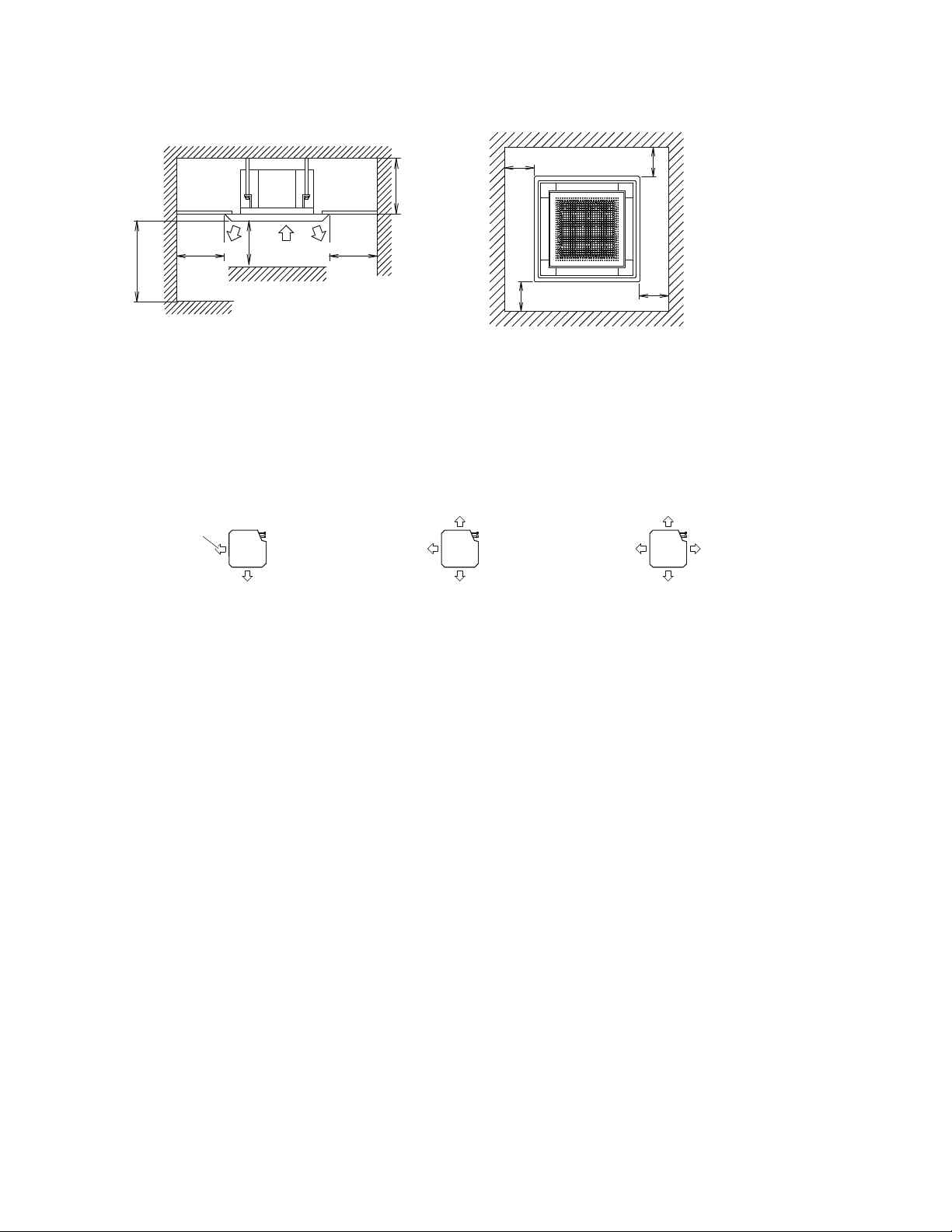
5 ŶEspañol
Selección del sitio de instalación
4GSWGTKOKGPVQURCTCGNGURCEKQFGKPUVCNCEKÏP
ű60
(1500)
ű11-3/4
(300)
ű98 (2500)
*
ű60
(1500)
*
ű60
(1500)
Para la instalación
en lugares elevados
Salida
del aire
Salida del aire
Entrada
de aire
*
ű60 (1500)
*
ű60 (1500)
unidad: inch (mm)
*
ű60
(1500)
*
ű60
(1500)
r Deje 8 inch (200mm) o más espacio en el área marcada con
*
, en los lados donde la salida del aire esté cerrada.
&KTGEEKÏPFGNƃWLQFGCKTG
r La dirección del aire mostrada es un ejemplo.
r Seleccione el número apropiado de direcciones de acuerdo con la forma de la habitación y la ubicación de la unidad. (Al
UGNGEEKQPCTQFKTGEEKQPGUNCEQPƂIWTCEKÏPFGECORQFGDGUGTTGCNK\CFCWUCPFQGNEQPVTQNTGOQVQ[NCUTGLKNNCUFGXGPVKNCEKÏP
deben cerrarse.
Consulte el manual de instalación del kit de almohadilla de bloqueo (vendido por separado) para más detalles).
&KTGEEKÏPFGNƃWLQFGCKTG (ejemplo)
Tubería
Salida
del aire
Tubería Tubería
Salida del aire en 2 direcciones Salida del aire en 3 direcciones Salida del aire en 4 direcciones
7UGRGTPQUFGUWURGPUKÏPRCTCNCKPUVCNCEKÏP%QORTWGDGUKGNVGEJQGUNQUWƂEKGPVGOGPVGHWGTVG
EQOQRCTCUQRQTVCTGNRGUQFGNCWPKFCF5KJC[TKGUIQUTGHWGTEGGNVGEJQCPVGUFGKPUVCNCTNC
unidad.
(El ángulo de instalación está marcado en la plantilla. Consúltelo para comprobar los puntos que requieren refuerzos).
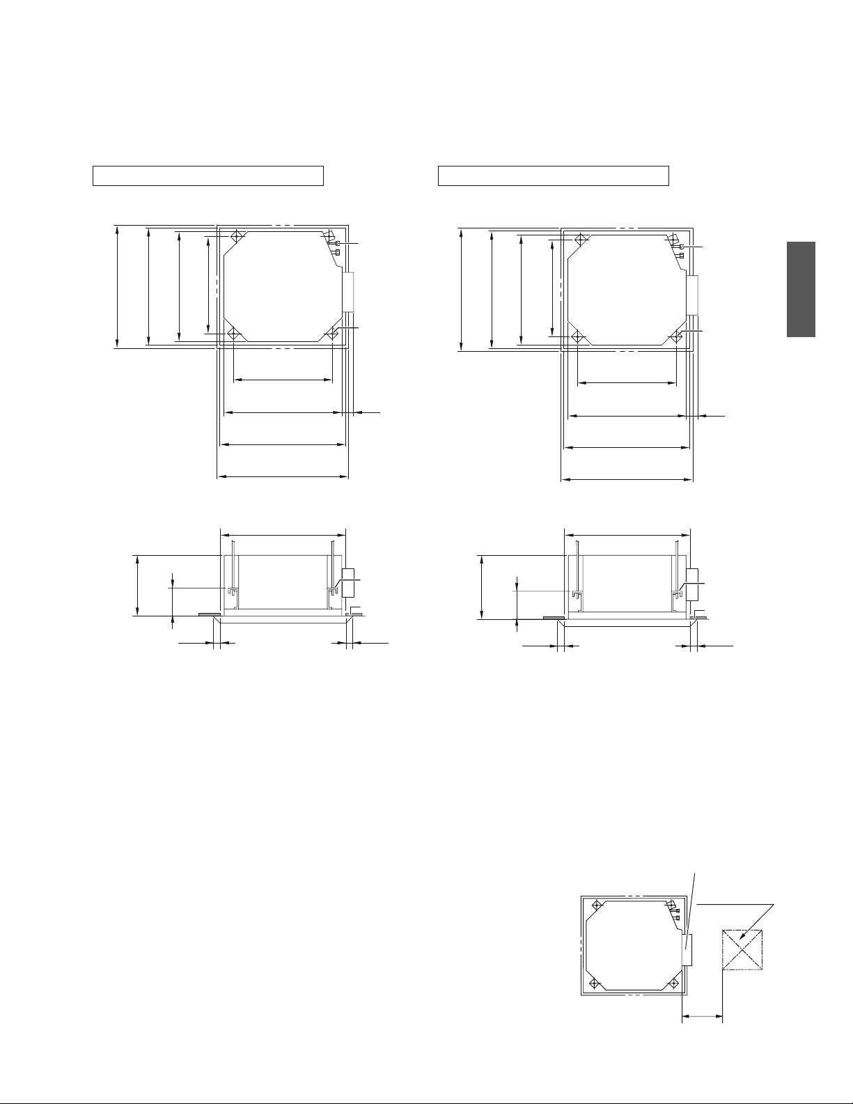
6ŶEspañol
Instalación de la unidad interior
1. 4GNCEKÏPGPVTGNCCDGTVWTCFGVGEJQ[NCWPKFCF[NCRQUKEKÏPFGNRGTPQFG
suspensión
Vista superior
Vista lateral
Tubería
refrigerante
Perno de
suspensión
(×4)
Techo falso
7-1/16
(180)
ű
*
13/16
(20)
ű
*
13/16
(20)
2-1/2
(63)
27-9/16 (700)
Panel de decoración
22-5/8 (575)
Unidad interior
21 (533)
Distancia entre pernos de suspensión
23-1/16-26 (585-660)
Abertura de techo
23-1/16-26 (585-660)
Abertura de techo
27-9/16 (700)
Panel de decoración
23-1/16-26 (585-660)
Abertura de techo
22-5/8 (575)
Unidad interior
21 (533)
Distancia entre pernos de suspensión
Soporte
colgante
Tubería
refrigerante
Perno de
suspensión
(×4)
24-7/16 (620)
Panel de decoración
7-1/2
(190)
23-1/16-23-7/16 (585-595)
Abertura de techo
22-5/8 (575)
Unidad interior
24-7/16 (620)
Panel de decoración
23-1/16-23-7/16 (585-595)
Abertura de techo
ű
*
1/2
(12.5)
ű
*
1/2
(12.5)
22-5/8 (575)
Unidad interior
2-1/2
(63)
21 (533)
Distancia entre pernos de suspensión
Techo falso
23-1/16-23-7/16 (585-595)
Abertura de techo
21 (533)
Distancia entre pernos de suspensión
Vista superior
Vista lateral
unidad: inch (mm)
Para panel de decoración tipo B
Para panel de decoración tipo A
Soporte
colgante
11-3/4
(298)
11-1/4
(285)
NOTA
r *Si el panel no se extiende sobre el techo por esta cantidad, complemente con material de techo adicional o restaure el techo.
r Instale la abertura de inspección en el lado de la caja de cableado eléctrico donde
puedan realizarse con facilidad las tareas de mantenimiento e inspección de la caja de
cableado eléctrico y la bomba de drenaje.
Abertura de
inspección
Caja de cableado eléctrico
11-3/4
(300)
17-11/16×17-11/16
(450×450)
Español
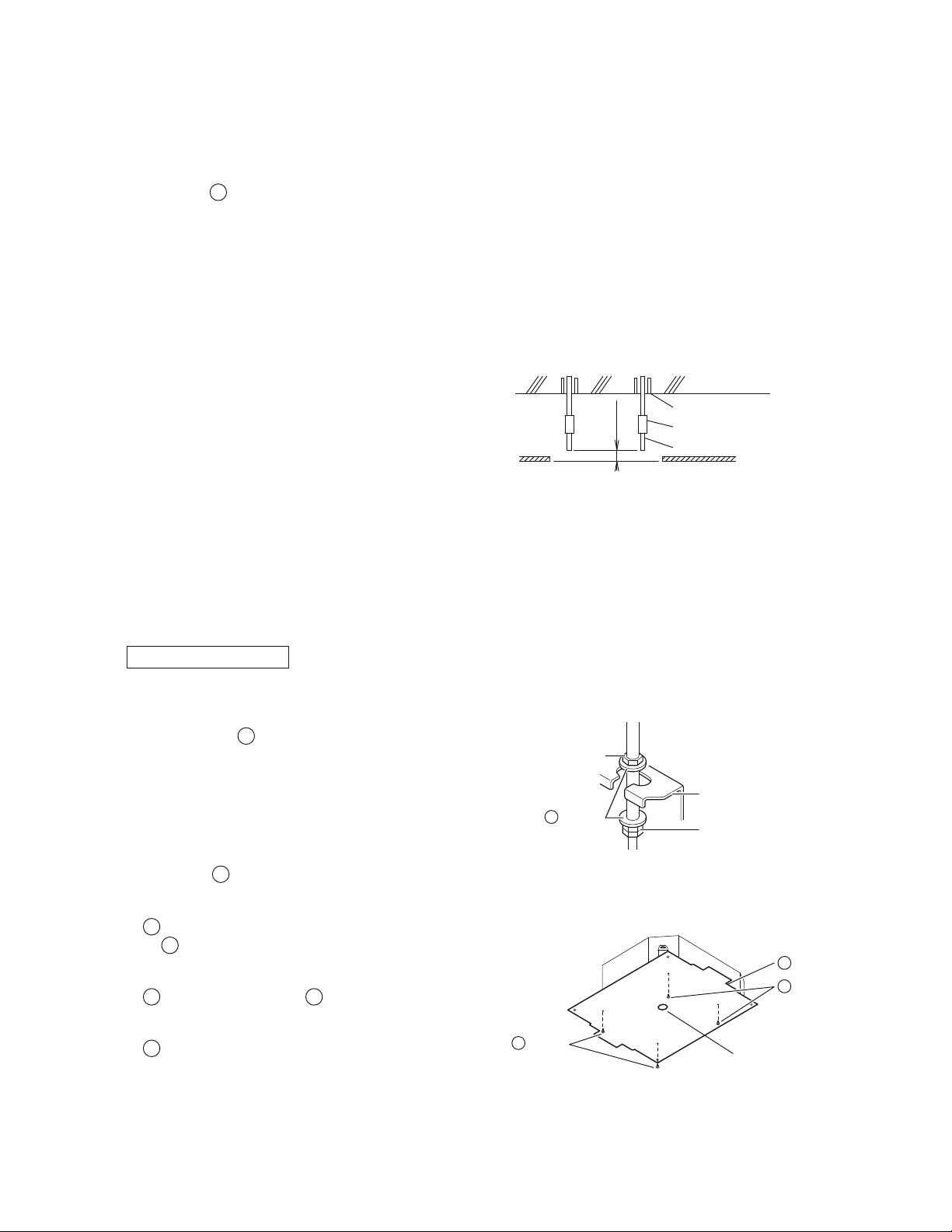
7 ŶEspañol
Instalación de la unidad interior
2. %TGCEKÏPFGNCCDGTVWTCFGVGEJQPGEGUCTKCRCTCNCKPUVCNCEKÏPUKHWGUG
aplicable
RCTCVGEJQUGZKUVGPVGU
r Consulte la
E
plantilla para más información sobre las dimensiones de la abertura de techo.
r Cree la abertura de techo necesaria para la instalación. Desde el lado de la abertura a la salida de la carcasa, instale la
tubería refrigerante y de drenaje y el cableado del control remoto (no necesario para el tipo inalámbrico) y el cableado
entre unidades. Consulte cada sección de Trabajos de tubería de drenaje o Cableado.
r Después de perforar una abertura en el techo, podría ser necesario reforzar las vigas del techo para mantener el techo
nivelado y evitar que vibre. Consulte con el constructor para obtener más detalles.
3. Instalación de los pernos de suspensión
7UGWPRGTPQFGVCOCÍQ//QGSWKXCNGPVG
7UGWPCPENCLGRCTCQTKƂEKQGPNQUVGEJQUGZKUVGPVGU[
un inserto hundido, anclaje hundido u otro tipo de piezas
no suministradas para los techos nuevos de modo que
refuercen la estructura y sean capaces de soportar el peso
de la unidad.
Ajuste el juego (2-4 inch (50-100mm)) del techo antes de
seguir adelante.
r Todas las piezas anteriores no se suministran.
2-4
(50-100)
unidad: inch (mm)
Anclaje
Placa de techo
Ejemplo de instalación
Tuerca larga o tensor
Perno de suspensión
Techo falso
4. Instalación de la unidad interior
#NKPUVCNCTCEEGUQTKQUQREKQPCNGUGZEGRVQGNRCPGNFGFGEQTCEKÏPNGCVCODKÅPGNOCPWCNFGKPUVCNCEKÏPFGNQU
CEEGUQTKQUQREKQPCNGU&GRGPFKGPFQFGNCUEQPFKEKQPGUFGECORQRQFTÉCUGTO½UH½EKNKPUVCNCTNQUCEEGUQTKQU
QREKQPCNGUCPVGUFGKPUVCNCTNCWPKFCFKPVGTKQT5KPGODCTIQRCTCNQUVGEJQUGZKUVGPVGUKPUVCNGUKGORTGGNMKVFG
entrada de aire fresco antes de instalar la unidad.
En cuanto a las piezas usadas para el trabajo de instalación, asegúrese de usar los accesorios suministrados y las piezas
GURGEKƂECFCUFGUKIPCFCURQT&CKMKP
2CTCVGEJQUPWGXQU
1) Instale la unidad interior temporalmente.
r Fije el soporte colgante en el perno de suspensión.
#UGIÖTGUGFGƂLCTNQFGHQTOCUGIWTCOGFKCPVGGNWUQ
de una tuerca y
C
arandela desde los lados superior e
inferior del soporte colgante.
Soporte colgante
Tuerca doble
(no suministrada, apriete)
Tuerca
(no suministrada)
Arandela
C
Fijación del soporte colgante
2) Consulte la
E
plantilla para más información sobre las dimensiones de la abertura de techo.
Consulte con el constructor o carpintero para más detalles.
r El centro de la abertura de techo se indica en la
E
plantilla. Esta marca también indica el centro de la unidad.
r La
E
plantilla puede girarse 90° para poder indicar las
dimensiones correctas en los 4 lados.
r Después de cortar la plantilla del embalaje, conecte la
E
plantilla a la unidad con
F
tornillos (×4) como se
OWGUVTCGPNCƂIWTC
r La altura del techo se muestra en el lateral de la
E
plantilla. Ajuste la altura de la unidad de acuerdo con
esta indicación.
Instalación de plantilla
Plantilla
E
Tornillos
F
TornillosF
Centro de la abertura
de techo
6TCDCLQGPGNVGEJQ
3) Ajuste la unidad en la posición correcta para la instalación.
(Consulte 4GNCEKÏPGPVTGNCCDGTVWTCFGVGEJQ[NCWPKFCF[NCRQUKEKÏPFGNRGTPQFGUWURGPUKÏP).
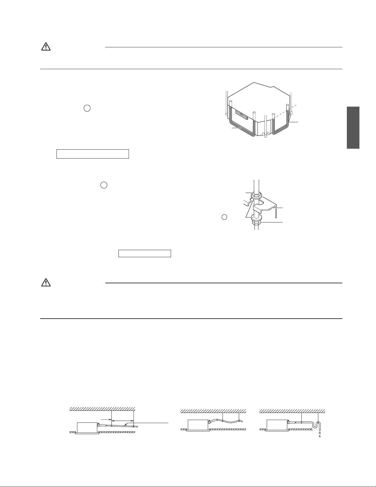
8ŶEspañol
PRECAUCIÓN
5KNCWPKFCFUGKPENKPCEQPVTCGNƃWLQFGEQPFGPUCFQGNKPVGTTWRVQTƃQVCFQTRQFTÉCHWPEKQPCTKPEQTTGEVCOGPVG[ECWUCTSWGGN
agua gotee.
4) Compruebe que la unidad está nivelada horizontalmente.
r La unidad interior está equipada con una bomba de
FTGPCLGKPVGITCFC[WPKPVGTTWRVQTƃQVCFQT%QORTWGDG
la nivelación usando un nivelador de agua o un tubo de
vinilo con agua.
5) Retire la
E
plantilla.
Nivelador de agua
Tubo de vinilo
Tubo de vinilo
Mantenimiento de la horizontalidad
2CTCVGEJQUGZKUVGPVGU
1) Instale la unidad interior temporalmente.
r Fije el soporte colgante en el perno de suspensión.
Asegúrese de fijarlo de forma segura mediante el uso
de una tuerca y
C
arandela desde los lados superior e
inferior del soporte colgante.
Soporte colgante
Tuerca doble
(no suministrada, apriete)
Tuerca
(no suministrada)
Arandela
C
Fijación del soporte colgante
2) Ajuste la altura y la posición de la unidad.
(Consulte 4GNCEKÏPGPVTGNCCDGTVWTCFGVGEJQ[NCWPKFCF[NCRQUKEKÏPFGNRGTPQFGUWURGPUKÏP).
3) Realice los pasos 4) en
2CTCVGEJQUPWGXQU
.
5. Trabajos de tubería de drenaje
PRECAUCIÓN
r La acumulación de agua en la tubería de drenaje puede causar que el drenaje se obstruya.
r
0QEQPGEVGGNVWDQFGFTGPCLGFKTGEVCOGPVGCVWDGTÉCUFGCIWCUTGUKFWCNGUEQPQNQTCCOQPKCEQ'NCOQPKCEQGPGNCIWC
TGUKFWCNRWGFGRGPGVTCTGPNCWPKFCFKPVGTKQTCVTCXÅUFGNQUVWDQUFGFTGPCLG[EQTTQGTGNKPVGTECODKCFQTFGECNQT
r 6GPICGPEWGPVCSWGGNVWDQFGFTGPCLGUGDNQSWGCUKGNCIWCUGCEWOWNCGPÅN
1. Instalación de la tubería de drenaje
r +PUVCNGNCVWDGTÉCFGFTGPCLGEQOQUGOWGUVTCGPNCƂIWTC[VQOGOGFKFCUEQPVTCNCEQPFGPUCEKÏP.CUVWDGTÉCU
indebidamente manipuladas podrían dar lugar a fugas y, con el tiempo, mojar los muebles y las pertenencias.
r Mantenga la tubería lo más corta posible e inclínela hacia abajo con un gradiente de al menos 1/100 de manera que
el aire no pueda quedar atrapado dentro de la tubería.
r /CPVGPICGNVCOCÍQFGNVWDQKIWCNQOC[QTSWGGNFGNVWDQEQPGEVQTVWDQFGXKPKNQEQPWPFK½OGVTQPQOKPCNFG
inch (20mm) y un diámetro exterior 1 inch (26mm)).
r Empuje la manguera de drenaje suministrada tanto como sea posible sobre la toma de drenaje.
r 5KNCOCPIWGTCFGFTGPCLGPQRWGFGCLWUVCTUGUWƂEKGPVGOGPVGGPRGPFKGPVGEQPUWNVGp2TGECWEKQPGUFGNCVWDGTÉC
FGGNGXCEKÏPFGFTGPCLGq.
r Para evitar que la manguera de drenaje pierda tensión, espacie el soporte colgante cada 40-60 inch (1000-1500mm).
Pendiente de
1/100 o superior
Soporte colgante
CORRECTO
40-60 inch
(1000-1500mm)
INCORRECTO INCORRECTO
Español
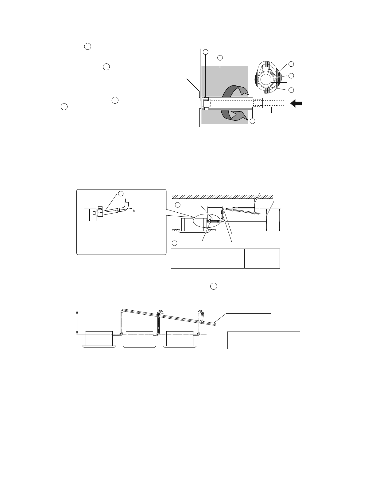
9 ŶEspañol
Instalación de la unidad interior
r Apriete el
B
metal de sujeción como se indica en la
ilustración.
r 7PCXG\ƂPCNK\CFCNCRTWGDCFGNCVWDGTÉCFG
drenaje, instale la
J
almohadilla de sellado de
drenaje (grande) suministrada con la unidad sobre la
parte descubierta de la toma de drenaje (= entre la
manguera de drenaje y el cuerpo de la unidad).
r Envuelva la almohadilla de sellado grande
suministrada sobre el
B
metal de sujeción y la
A
OCPIWGTCFGFTGPCLGRCTCCKUNCTNC[ƂLCTNCEQP
sujeciones.
r #ÉUNGVQFCNCVWDGTÉCFGFTGPCLGFGPVTQFGNGFKƂEKQPQ
suministrada).
r Si la manguera de drenaje no puede ajustarse
UWƂEKGPVGOGPVGGPRGPFKGPVGKPUVCNGNCOCPIWGTCEQP
la tubería de elevación de drenaje (no suministrada).
Metal de sujeciónB
Metal de sujeciónB
Almohadilla de
sellado (grande)
J
Almohadilla de
sellado (grande)
J
Toma de drenaje
Toma de drenaje
Tubería de drenaje (no suministrada)
Manguera de drenajeA
Manguera de drenajeA
Vista A
A
2TGECWEKQPGUFGNCVWDGTÉCFGGNGXCEKÏPFGFTGPCLG
r Instale los tubos de elevación de drenaje a una altura de menos de H2.
r Instale los tubos de elevación de drenaje en ángulo recto a la unidad interior y a no más de 11-3/4 inch (300mm) de la
unidad.
Ajustable
Placa de techo
Ű11-3/4
(300)
40-60
(1000-1500)
unidad: inch (mm)
Soporte colgante
33-7/16
(850)
H2H1
Nivelada o
ligeramente
inclinada hacia
arriba
Para evitar burbujas de aire en la manguera
de drenaje, manténgala nivelada o
ligeramente inclinada hacia arriba. Cualquier
burbuja en la manguera podría hacer que la
WPKFCFGOKVCTWKFQUFGDKFQCNƃWLQFGTGVQTPQ
cuando se detiene la bomba de drenaje.
Metal de sujeciónB
Manguera
de drenaje
A
Manguera de drenajeA
Tubería de elevación de drenaje
Sección de elevación
Panel de decoración
H1 H2
Tipo A 8-1/16 (205) Ű25-3/8 (645)
Tipo B 8-11/16 (220) Ű24-13/16 (630)
r Para garantizar que no se aplican presiones excesivas sobre la
A
manguera de drenaje incluida, no doble ni
retuerza la manguera al instalarla, podría causar fugas.
r Si convergen múltiples tubos de drenaje, instale de acuerdo con el procedimiento que se muestra a continuación.
Tubo de drenaje central
0–25-3/8 inch
(0-645mm)
El tubo de drenaje debe poseer una
pendiente descendiente de al menos 1/100
para evitar la formación de bolsas de aire.
La acumulación de agua en la tubería
de drenaje puede causar que el
drenaje se obstruya.
Seleccione tubos de drenaje convergentes con medidores adecuados para la capacidad de funcionamiento de la unidad.
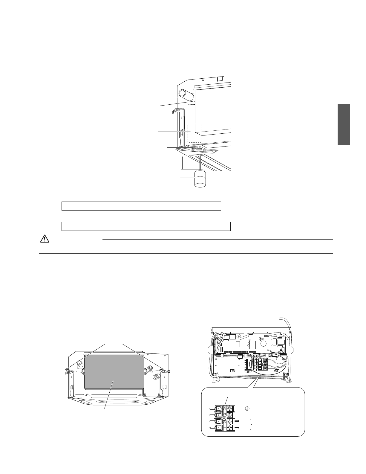
10ŶEspañol
7PCXG\ƂPCNK\CFCUNCUVCTGCUFGKPUVCNCEKÏPFGNCUVWDGTÉCUEQORTWGDGUKGNFTGPCLGƃW[G
UWCXGOGPVG
r #ÍCFCCRTQZKOCFCOGPVGICNFGCIWCNGPVCOGPVGFGUFGNCUCNKFCFGNCKTG[EQORTWGDGGNƃWLQFGNFTGPCLG
unidad: inch (mm)
Método de adición de agua
Tubo de drenaje
Toma de drenaje
(punto de visión
FGNƃWLQFGCIWC
Ubicación de la
bomba de drenaje
Contenedor de plástico para
vertidos
El tubo debe ser de
aproximadamente 4 inch
OOFGNCTIQ
Salida de drenaje de
servicio
EQPVCRÏPFGIQOC
Use esta salida para
FTGPCTGNCIWCFGN
EQNGEVQTFGFTGPCLG
ű
(100)
%WCPFQGNVTCDCLQFGECDNGCFQGNÅEVTKEQJCƂPCNK\CFQ
r
%QORTWGDGGNƃWLQFGFTGPCLGFWTCPVGNCQRGTCEKÏP(4©1GZRNKECFCGPp1RGTCEKÏPFGGPUC[Q[RTWGDCq en la página 17.
%WCPFQGNVTCDCLQFGECDNGCFQGNÅEVTKEQPQJCƂPCNK\CFQ
PRECAUCIÓN
.QUVTCDCLQUFGNECDNGCFQGNÅEVTKEQFGDGPUGTTGCNK\CFQURQTWPGNGEVTKEKUVCEGTVKƂECFQ
r 5KCNIWKGPUKPNCUECNKƂECEKQPGUCRTQRKCFCUTGCNK\CGNVTCDCLQNNGXGCECDQNCUUKIWKGPVGUCEEKQPGUFGURWÅUFG
completar la operación de ensayo.
1)
Extraiga la cubierta de la caja de cableado eléctrico (2 tornillos). Conecte el suministro de alimentación monofásico
/101(5+%1|*\8CNCUEQPGZKQPGUPÖO[PÖOFGNDNQSWGFGVGTOKPCNGUFGNUWOKPKUVTQFGCNKOGPVCEKÏP
No conecte al núm. 3 del bloque de terminales del suministro de alimentación o la bomba de drenaje no funcionará.
Al realizar trabajos de cableado alrededor de la caja de cableado eléctrico, asegúrese de no tocar ninguno de los conectores.
Asegúrese de instalar la cubierta de la caja de cableado eléctrico antes de activar la alimentación.
2) &GURWÅUFGEQPƂTOCTGNFTGPCLGCRCIWGGNUWOKPKUVTQFGCNKOGPVCEKÏP[TGVKTGUWECDNGCFQ
3) Fije la cubierta de la caja de cableado eléctrico como antes.
Tornillos
Cubierta de la caja de cableado eléctrico
Masa
Bloque de terminales del suministro de alimentación
Suministro de alimentación
monofásico (60Hz 208/230V)
No.2
No.1
Español
11 ŶEspañol
Instalación de la unidad interior
6. Cableado
%QPUWNVGVCODKÅPGNOCPWCNFGKPUVCNCEKÏPRCTCNCWPKFCFGZVGTKQT
ADVERTENCIA
r No use cables encintados, cables de extensión ni conexiones de estrella, ya que podrían causar sobrecalentamiento,
descargas eléctricas o incendios.
r 0QWUGRCTVGUGNÅEVTKECUEQORTCFCUNQECNOGPVGGPGNKPVGTKQTFGNRTQFWEVQ0QTCOKƂSWGNCCNKOGPVCEKÏPFGNCDQODCFG
drenaje, etc., desde el bloque de terminales.) Hacerlo podría causar descargas eléctricas o un incendio.
r No conecte el cable de alimentación a la unidad interior. Hacerlo podría causar descargas eléctricas o un incendio.
PRECAUCIÓN
r Cuando conecte el cable de conexión al bloque de terminales usando un cable
de un solo núcleo, asegúrese de realizar la ondulación.
Los problemas con la instalación pueden producir calor e incendios.
Correcto Incorrecto
r #NƂLCTECDNGUWUGGNOCVGTKCNFGUWLGEKÏPKPENWKFQRCTCGXKVCTCRNKECTRTGUKÏPGZVGTKQTUQDTGNCUEQPGZKQPGUFGNECDNGCFQ[
ƂLGƂTOGOGPVG#NKPUVCNCTGNECDNGCFQCUGIÖTGUGFGSWGGNECDNGCFQGUVÅQTFGPCFQ[SWGPQECWUGSWGNCEWDKGTVCFGNC
ECLCFGECDNGCFQGNÅEVTKEQUQDTGUCNICCEQPVKPWCEKÏPEKGTTGNCEWDKGTVCƂTOGOGPVG
r Fuera de la unidad, separe el cableado de baja tensión (cableado del control remoto) y el cableado de alta tensión
(cableado entre unidades, tierra y otro cableado de alimentación) al menos 2 in., de tal forma que no pasen a través del
mismo lugar. La proximidad puede causar interferencias eléctricas, averías y roturas.
2CTFGCRTKGVGFGNQUDNQSWGUFGVGTOKPCNGU
r Use el destornillador correcto para apretar los tornillos de los terminales. Si la punta del destornillador es demasiado
RGSWGÍCRQFTÉCECWUCTFCÍQUUQDTGNCECDG\CFGNVQTPKNNQ[ÅUVGPQSWGFCT½EQTTGEVCOGPVGCRTGVCFQ
r 5KCRTKGVCGZEGUKXCOGPVGNQUVQTPKNNQUFGNQUVGTOKPCNGURQFTÉCPTGUWNVCTFCÍCFQU
r Consulte la siguiente tabla para más información sobre el par de apriete los tornillos de los terminales.
WPKFCFNDHrHV0rO
Par de apriete
Bloque de terminales del control remoto (6P) 0.58 - 0.72 (0.79 - 0.98)
Bloque de terminales del suministro de alimentación (4P) 0.87 - 1.06 (1.18 - 1.44)
12ŶEspañol
2TGECWEKQPGURCTCGNECDNGCFQFGNUWOKPKUVTQFGCNKOGPVCEKÏP
Use un terminal de estilo prensado redondo para la conexión del suministro de alimentación al bloque de terminales. Si no
puede usarse por motivos inevitables, asegúrese de respetar las siguientes instrucciones:
r 2CTCGNECDNGCFQCUGIÖTGUGFGSWGUGWVKNK\CPNQUECDNGURTGUETKVQUUGTGCNK\CPNCUEQPGZKQPGUEQORNGVCU[UGƂLCPNQU
cables de modo que no puedan aplicarse fuerzas externas sobre los terminales.
Instalar manguito aislante
Cableado
Terminal de estilo prensado redondo
r Use únicamente cable de cobre.
r Para el trabajo de cableado eléctrico, consulte también la p'VKSWGVCFGNFKCITCOCGNÅEVTKEQq instalada en la cubierta de
la caja de cableado eléctrico.
r Para más información sobre el cableado del control remoto, consulte el manual de instalación suministrado con el control
remoto.
r Deberá instalar un disyuntor capaz de cortar el suministro de alimentación de todo el sistema.
r 'URGEKƂECEKQPGUFGNECDNGFGECORQ
Adquiera localmente el cableado del control remoto.
Tabla 3
Cable 6COCÍQ Longitud (ft.)
Cableado entre unidades
'NVCOCÍQ[NCNQPIKVWFFGNECDNGFGDGP
cumplir con los códigos locales.
––
Cableado del control remoto Enfundado (2 hilos) AWG 18 - 16 Máx.1640*
Cableado al terminal de tierra
'NVCOCÍQ[NCNQPIKVWFFGNECDNGFGDGP
cumplir con los códigos locales.
––
* Esta será la longitud extendida total en el sistema al realizar el control de grupo.
PRECAUCIÓN
r Organice los cables y fije una cubierta firmemente para que la cubierta no flote durante los trabajos de cableado.
r No sujete el cableado del control remoto con el cableado entre unidades. Hacerlo puede provocar una avería.
r 'NECDNGCFQFGNEQPVTQNTGOQVQ[GNECDNGCFQGPVTGWPKFCFGUFGDGPGUVCTCNOGPQU|KPEJOOFGNTGUVQFGQVTQUECDNGU
eléctricos.
No seguir esta pauta podría provocar una avería debido al ruido eléctrico.
Español
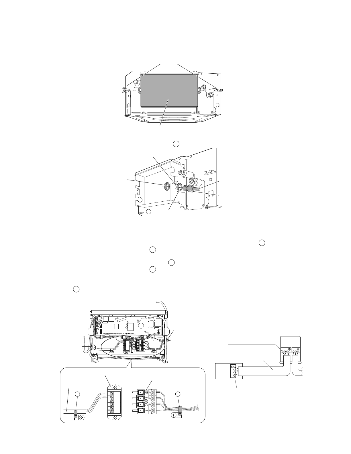
13 ŶEspañol
Instalación de la unidad interior
%QPGZKÏPFGNECDNGCFQGPVTGWPKFCFGUECDNGFGVKGTTC[ECDNGCFQFGNEQPVTQNTGOQVQ
Cableado entre unidades y cable de tierra
1) Extraiga la cubierta de la caja de cableado eléctrico (2 tornillos).
Tornillos
Cubierta de la caja de cableado eléctrico
2) +PVTQFW\ECNQUECDNGUKPENW[GPFQGNECDNGFGVKGTTCGPGNEQPFWEVQ[CUGIWTGGNEQPFWEVQCNQTKƂEKQFGNCECLCFG
cableado eléctrico mediante una tuerca de bloqueo y la
N
arandela para conducto, como se muestra en la ilustración.
Tuerca de bloqueo
(no suministrada)
Conducto
(no suministrada)
1TKƂEKQGPNCECLCFG
cableado eléctrico
Arandela para conducto
N
Tubo de conducto
3) Conecte el cable de toma a tierra en los terminales correspondientes.
4)
Haga coincidir los colores de los cables con los números de terminal del bloque de terminales del suministro de alimentación
FGNCWPKFCFKPVGTKQT[GZVGTKQT[CUGIWTGƂTOGOGPVGNQUECDNGUGPNQUVGTOKPCNGUEQTTGURQPFKGPVGUWUCPFQVQTPKNNQU
5) #NJCEGTNQVKTGFGNQUECDNGUGPGNKPVGTKQTCVTCXÅUFGNQTKƂEKQ[ƂLGNQUECDNGUƂTOGOGPVGEQPNC
D
sujeción incluida.
6) 2GTOKVCUWƂEKGPVGJQNIWTCFGECDNGUGPVTGNC
D
sujeción y el bloque de terminales del suministro de alimentación.
7)
6KTGFGNQUECDNGUGPGNKPVGTKQTCVTCXÅUFGNQTKƂEKQ[EQPÅEVGNQUCNDNQSWGFGVGTOKPCNGUFGNEQPVTQNTGOQVQUKPRQNCTKFCF
(KLGƂTOGOGPVGGNECDNGCFQFGNEQPVTQNTGOQVQEQPNC
D
sujeción incluida.
8) 2GTOKVCUWƂEKGPVGJQNIWTCFGECDNGUGPVTGNC
D
sujeción y el bloque de terminales del control remoto.
9) Fije la cubierta de la caja de cableado eléctrico como antes.
10) &GURWÅUTGCNK\CTVQFCUNCUEQPGZKQPGUFGNECDNGCFQNNGPGNQUGURCEKQUFGNQUQTKƂEKQUFGECDNGCFQFGNCECTECUCEQP
masilla o
M
CNOQJCFKNNCFGUGNNCFQRGSWGÍCRCTCGXKVCTSWGRGSWGÍQUCPKOCNGUQUWEKGFCFRGPGVTGPGPNCWPKFCF
desde el exterior y causen cortocircuitos en la caja de cableado eléctrico.
Bloque de terminales del control remoto
Sujeción
D
Bloque de terminales del
suministro de alimentación
Sujeción
D
Abertura para cable
Cableado del control
remoto
Conducto
123
123
L1 L
2
(KLGƂTOGOGPVGNQUECDNGU
EQPNQUVQTPKNNQUFGVGTOKPCN
7PKFCF
GZVGTKQT
7PKFCF
KPVGTKQT
(KLGƂTOGOGPVGNQUECDNGU
EQPNQUVQTPKNNQUFGVGTOKPCN
'NVCOCÍQ[NCNQPIKVWF
FGNECDNGFGDGPEWORNKT
EQPNQUEÏFKIQUNQECNGU
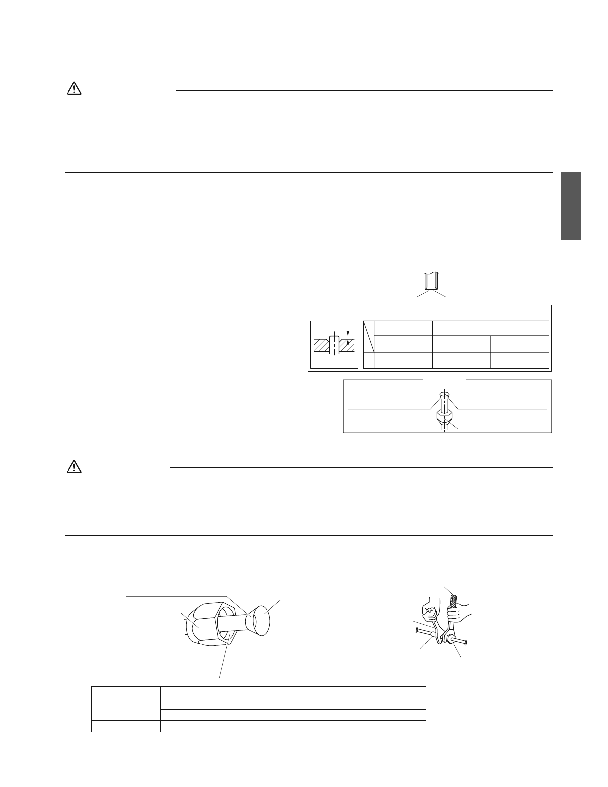
14ŶEspañol
Trabajos de tubería refrigerante
%QPUWNVGVCODKÅPGNOCPWCNFGKPUVCNCEKÏPRCTCNCWPKFCFGZVGTKQT
ADVERTENCIA
r No aplique aceite mineral en la parte abocinada.
r Evite que el aceite mineral penetre en el sistema, ya que reduciría la vida útil de servicio de las unidades.
r
Nunca use tuberías que ya hayan sido usadas en otras instalaciones. Use únicamente las piezas suministradas con la unidad.
r Nunca instale un secador en esta unidad R410A para garantizar su vida útil de servicio.
r 'NOCVGTKCNUGECPVGRQFTÉCFKUQNXGTUG[FCÍCTGNUKUVGOC
r Un abocinamiento incompleto podría causar fugas de gas refrigerante.
4GCNKEGEQORNGVCOGPVGNCUVCTGCUFGCKUNCOKGPVQVÅTOKEQGPCODQUNCFQUFGNCVWDGTÉCFGICU[NÉSWKFQ&GNQEQPVTCTKQ
podrían aparecer fugas de agua.
#UGIÖTGUGFGWUCTCKUNCPVGFKUGÍCFQRCTCUWWUQEQPUKUVGOCU*8#%
#FGO½UGPNQUECUQUGPNQUSWGNCVGORGTCVWTC[NCJWOGFCFFGNCUUGEEKQPGUFGNCVWDGTÉCTGHTKIGTCPVGRWGFCP
GZEGFGT(%Q*4TGHWGTEGGNCKUNCOKGPVQFGNTGHTKIGTCPVGKPEJOOQO½UITWGUQ2QFTÉCCRCTGEGT
EQPFGPUCEKÏPGPNCUWRGTƂEKGFGNOCVGTKCNCKUNCPVG
#PVGUFGNQUVTCDCLQUFGVWDGTÉCTGHTKIGTCPVGEQORTWGDGGNVKRQFGTGHTKIGTCPVGWUCFQ.CQRGTCEKÏPEQTTGEVCPQGU
posible si los tipos de refrigerante son distintos.
1. #DQEKPCOKGPVQFGNGZVTGOQFG
tubo
1) Corte el extremo del tubo con un cortatubos.
2) 4GVKTGNCUTGDCDCUEQPNCUWRGTƂEKGFGEQTVG
orientada hacia abajo de modo que las virutas no
penetren en el interior del tubo.
3) Coloque la tuerca abocinada en el tubo.
4) Abocine el tubo.
5) Compruebe que el abocinamiento se haya realizado
correctamente.
A
A
Corte exactamente
en ángulos rectos.
Retire las rebabas.
Abocinamiento
Ajuste exactamente en la posición que se muestra a continuación.
Troquel
0-0.020 inch
(0-0.5mm)
Tipo de embrague
Herramienta abocinada
para R410A
0.039-0.059 inch
(1.0-1.5mm)
Tipo de embrague
(Tipo rígido)
0.059-0.079 inch
(1.5-2.0mm)
Tipo de mariposa
(tipo imperial)
Herramienta abocinada convencional
.CUWRGTƂEKGKPVGTKQTSWGUG
va a abocinar debe estar
libre de imperfecciones.
El extremo de tubo debe estar
uniformemente abocinado en
un círculo perfecto.
Asegúrese de que la tuerca abocinada
esté correctamente instalada.
Comprobar
2. Tubería refrigerante
PRECAUCIÓN
r Use la tuerca abocinada fijada a la unidad principal. (Con ello evitará el agrietamiento de la tuerca abocinada como
resultado de su deterioro por el paso del tiempo).
r Para evitar fugas de gas, aplique aceite de refrigeración únicamente sobre la superficie interior del abocinamiento. (Use
aceite de refrigeración para R410A.)
r 7UGWPCNNCXGFKPCOQOÅVTKECCNCRTGVCTNCUVWGTECUCDQEKPCFCURCTCGXKVCTFCÍCTNCU[ECWUCTHWICUFGICU
r Alinee los centros de ambos abocinamientos y apriete las tuercas abocinadas 3 o 4 vueltas con la mano, enseguida
CRTKÅVGNCUEQORNGVCOGPVGEQPWPCNNCXGƂLC[WPCNNCXGFKPCOQOÅVTKEC
No aplique aceite de refrigeración
GPNCUWRGTƂEKGGZVGTKQT
Tuerca abocinada
Aplique aceite de refrigeración
ÖPKECOGPVGUQDTGNCUWRGTƂEKG
KPVGTKQTFGNCDQEKPCOKGPVQ
No aplique aceite de
refrigeración a la tuerca
abocinada para evitar pares de
CRTKGVGGZEGUKXQU
Aplicar aceite
Llave
dinamométrica
Unión de
tubería
Tuerca
abocinada
.NCXGƂLC
Apretar
6COCÍQFGNCVWDGTÉC Par de apriete de tuerca abocinada
Lado del gas
D.E. 3/8 inch (9.5mm) s+DHrHV0rO
D.E. 1/2 inch (12.7mm) s+DHrHV0rO
Lado del líquido D.E. 1/4 inch (6.4mm) s+DHrHV0rO
Español
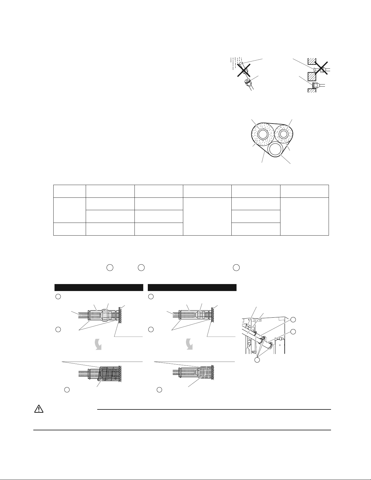
15 ŶEspañol
Trabajos de tubería refrigerante
2TGECWEKQPGUCNOCPKRWNCTVWDGTÉCU
r Proteja el extremo abierto de la tubería contra el polvo y la humedad.
r Todas las curvaturas de tubo deben realizarse lo más delicadamente
posible. Utilice un doblador de tubo para doblarlas.
Pared
Lluvia
Asegúrese de
colocar una tapa.
Si no hay ninguna tapa
abocinada disponible,
cubra el puerto de
abocinamiento con cinta
para evitar la penetración
de suciedad y agua.
5GNGEEKÏPFGOCVGTKCNGUVGTOQCKUNCPVGU[EQDTG
Al usar tubos de cobre y accesorios comerciales, respete lo siguiente:
r Material aislante: Espuma de polietileno
Tasa de transferencia de calor: 0.041 a 0.052W/mK (0.024 a 0.030Btu/fth°F
(0.035 a 0.045kcal/mh°C))
#UGIÖTGUGFGWUCTCKUNCPVGFGUKIPCFQRCTCUWWUQEQPUKUVGOCUFG*8#%
r Solamente tubo de cobre ACR (servicios de campo de aire acondicionado
y refrigeración).
Tubo de gas
Tubo de líquido
Aislamiento de
tubo de gas
Aislamiento de
tubo de líquido
Cinta de terminación
Manguera de drenaje
r Asegúrese de aislar el tubo de gas y el tubo de líquido y respete las dimensiones de aislamiento tal y como se indica a
continuación.
6COCÍQFGNC
tubería
Radio de curvatura
mínimo
Espesor de tubería
6COCÍQFG
aislamiento térmico
Espesor de
aislamiento térmico
Lado del
gas
D.E. 3/8 inch
(9.5mm)
1-3/16 inch (30mm)
o más
0.031 inch (0.8mm)
(C1220T-O)
D.I. 15/32-19/32 inch
(12-15mm)
13/32 inch (10mm)
mín.
D.E. 1/2 inch
(12.7mm)
1-9/16 inch (40mm)
o más
D.I. 9/16-5/8 inch
(14-16mm)
Lado del
líquido
D.E. 1/4 inch
(6.4mm)
1-3/16 inch (30mm)
o más
D.I. 5/16-13/32 inch
(8-10mm)
r Use tubos termoaislantes independientes para las tuberías de gas y refrigerante líquido.
r Asegúrese de realizar las tareas de aislamiento térmico en la sección de conexión de los tubos después de la
XGTKƂECEKÏPFGHWICFGICUGUVWFKCPFQFGVGPKFCOGPVGNCUUKIWKGPVGUƂIWTCU[WUCPFQNQUOCVGTKCNGUFGCKUNCOKGPVQ
térmico suministrados
G
aislante y
H
aislante. Fije ambos extremos con las
D
sujeciones.
Procedimiento de aislamiento de las tuberías
Tubería de gas Tubería de líquido
Sujeciones
(use 2 sujeciones por aislamiento)
D
Almohadilla de sellado media 1 para
tubería de gas
K Almohadilla de sellado media 2 para
tubería de líquido
L
Aislante
(para tubo de líquido)
HAislante
(para tubo de gas)
G
Tubería
de gas
Unidad
principal
Instalar en la
base
Conexión de tuerca
abocinada
Sujeciones
(use 2 sujeciones por aislamiento)
D
Tubería
de líquido
Unidad
principal
Instalar en la
base
Conexión de tuerca
abocinada
Envuelva desde la base de la unidad a la parte
superior de la conexión de la tuerca abocinada
Envuelva desde la base de la unidad a la parte
superior de la conexión de la tuerca abocinada
Tubo de gas
Tubo de líquido
Sujeciones
(use 2 sujeciones por aislamiento)
D
Aislante
(para tubo de líquido)
H
Aislante
(para tubo de gas)
G
PRECAUCIÓN
Asegúrese de aislar todas las tuberías de campo hasta la conexión de la tubería dentro de la unidad. Tocar una tubería
expuesta puede causar condensación o quemaduras.

16ŶEspañol
Instalación del panel de decoración
%QPGNEQPVTQNTGOQVQKPCN½ODTKEQPQRQFT½TGCNK\CTNCEQPƂIWTCEKÏPFGECORQ[NCQRGTCEKÏPFGGPUC[QUKPKPUVCNCTGN
panel de decoración.
Lea p1RGTCEKÏPFGGPUC[Q[RTWGDCq antes de realizar una operación de ensayo sin instalar el panel de decoración.
Consulte el manual de instalación suministrado con el panel de decoración.
Después de instalar el panel de decoración, asegúrese de que no haya espacio entre el cuerpo de la unidad y el panel de
decoración.
%QPƂIWTCEKÏPFGECORQ
PRECAUCIÓN
Si realiza la configuración de campo o la operación de ensayo sin colocar el panel de decoración, no toque la bomba de
drenaje. Puede ocasionar una descarga eléctrica.
r #UGIÖTGUGFGSWGNCEWDKGTVCFGNCECLCFGECDNGCFQGNÅEVTKEQGUV½EGTTCFCGPNCU
WPKFCFGUKPVGTKQT[GZVGTKQT
r .CEQPƂIWTCEKÏPFGECORQFGDGTGCNK\CTUGFGUFGGNEQPVTQNTGOQVQ[FGCEWGTFQ
con las condiciones de instalación.
r .CEQPƂIWTCEKÏPRWGFGTGCNK\CTUGECODKCPFQp0ÖOOQFQqp0¶/24+/'4%¯&+)1q[
p0¶/5')70&1%¯&+)1q
r .Cp%QPƂIWTCEKÏPFGECORQqKPENWKFCEQPGNEQPVTQNTGOQVQGPWOGTCGNQTFGPFGNQU
ajustes y el método de funcionamiento.
Unit No
0
1
–
01
5
–––
9
–––
13
–––
2
–
02
6
–––
10
–––
14
–––
3
–
01
7
–––
11
–––
15
–––
Field Settings
0
–
01
4
–––
8
–––
12
–––
Setting
Mode
20
1. Ajuste de la dirección de salida del aire
r Para cambiar la dirección de la salida del aire (2 o 3 direcciones), consulte el manual de instalación suministrado con el
kit de almohadilla de bloqueo (vendido por separado) o el manual de servicio.
0¶/5')70&1%¯&+)1GUV½CLWUVCFQRTGFGVGTOKPCFCOGPVGGPpqRCTCNCUCNKFCFGNCKTGGPFKTGEEKQPGU
2. %QPƂIWTCEKÏPFGQREKQPGU
r 2CTCNCEQPƂIWTCEKÏPFGNCUQREKQPGUEQPUWNVGGNOCPWCNFGKPUVCNCEKÏPRTQRQTEKQPCFQEQPNCQREKÏP
3. %QPƂIWTCEKÏPFGNCUGÍCNFGNƂNVTQFGCKTG
r .QUEQPVTQNGUTGOQVQUGUV½PGSWKRCFQUEQPWPCRCPVCNNCFGETKUVCNNÉSWKFQRCTCNCUUGÍCNGUFGNƂNVTQFGCKTGRCTC
XKUWCNK\CTGNOQOGPVQFGNKORKG\CFGNQUƂNVTQUFGCKTG
r 'NECODKQC0¶/5')70&1%¯&+)1FGRGPFGFGNCECPVKFCFFGRQNXQQUWEKGFCFFGNCJCDKVCEKÏP
0¶/5')70&1%¯&+)1GUV½CLWUVCFQRTGFGVGTOKPCFCOGPVGGPpqRCTCNCEQPVCOKPCEKÏPNKIGTCFGNƂNVTQFGCKTG
Ajuste
Tiempo hasta que se enciende la
lámpara del INDICADORA DEL
TIEMPO DE LIMPIEZA
DEL FILTRO DE AIRE
(tipo duradero)
Núm. modo
0¶/
PRIMER
%¯&+)1
0¶/
SEGUNDO
%¯&+)1
%QPVCOKPCEKÏPNKIGTCFGNƂNVTQFG
aire
Aprox. 2500 hrs
10 (20)
0
01
%QPVCOKPCEKÏPKPVGPUCFGNƂNVTQFG
aire
Aprox. 1250 hrs 02
Pantalla encendida
–3
01
Pantalla apagada 02
#NWUCTEQPVTQNGUTGOQVQUKPCN½ODTKEQU
r Al usar controles remotos inalámbricos, será necesario ajustar la dirección del control remoto inalámbrico. Consulte el
manual de instalación suministrado con el control remoto inalámbrico.
Español
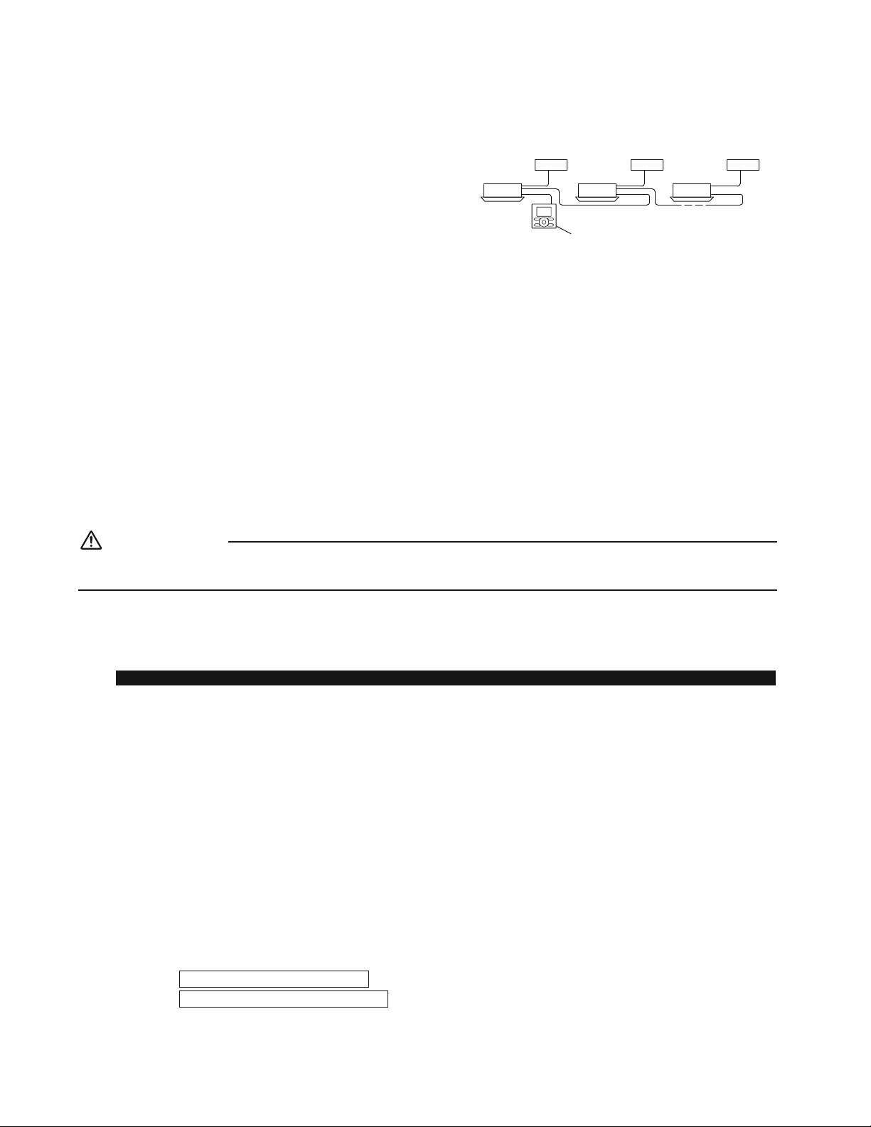
17 ŶEspañol
%QPƂIWTCEKÏPFGECORQ
4. #NKORNGOGPVCTGNEQPVTQNFGITWRQ
r Al usarse como unidad de par, podrá controlar hasta 16
unidades con el control remoto.
r
En este caso, todas las unidades interiores del grupo operarán
de acuerdo con el control remoto de control del grupo.
r
Seleccione un control remoto que coincida con tantas de las
funciones (persiana oscilante, etc.) del grupo como sea posible.
Unidad exterior
1
Unidad exterior
2
Unidad exterior
3
Unidad interior 1 Unidad interior 2
Control remoto de control de grupo
Unidad interior 3
/ÅVQFQFGECDNGCFQ (Consulte p%CDNGCFQq en page 11).
1) Retire la cubierta de la caja de cableado eléctrico.
2)
Cruce los hilos del bloque de terminales del control remoto (P
1
, P
2
) dentro de la caja de cableado eléctrico. (No hay polaridad).
(Consulte la Tabla 3 en p%CDNGCFQq en page 12)
5.
EQPVTQNGUTGOQVQUEQPVTQNFGWPKFCFKPVGTKQTOGFKCPVGEQPVTQNGUTGOQVQU
r #NWUCTEQPVTQNGUTGOQVQUWPQFGDGGUVCTCLWUVCFQGPp24+0%+2#.q[GNQVTQGPp5'%70+1q
/ÅVQFQFGECDNGCFQ (Consulte p%CDNGCFQq en page11).
1) Retire la cubierta de la caja de cableado eléctrico.
2)
#ÍCFCGNEQPVTQNTGOQVQCNDNQSWGFGVGTOKPCNGUFGNEQPVTQNTGOQVQ22GPNCECLCFGECDNGCFQGNÅEVTKEQ0QJC[RQNCTKFCF
(Consulte la Tabla 3 en p%CDNGCFQq en page 12)
Operación de ensayo y prueba
PRECAUCIÓN
5KTGCNK\CNCEQPƂIWTCEKÏPFGECORQQNCQRGTCEKÏPFGGPUC[QUKPEQNQECTGNRCPGNFGFGEQTCEKÏPPQVQSWGNCDQODCFG
drenaje. Puede ocasionar una descarga eléctrica.
r Después de terminar la construcción de la tubería refrigerante, tubería de drenaje y cableado eléctrico, realice la operación de
ensayo acordemente para proteger la unidad.
1. Operación de ensayo y prueba
Si usa el control remoto inalámbrico, asegúrese de instalar el panel de decoración antes de llevar a cabo la operación de ensayo.
r .CQRGTCEKÏPFGGPUC[QFGDGTGCNK\CTUGGPNCQRGTCEKÏP(4©1Q%#.14
/KFCNCVGPUKÏPFGUWOKPKUVTQ[CUGIÖTGUGFGSWGUGGPEWGPVTGFGPVTQFGNTCPIQ
GURGEKƂECFQ
'PNCQRGTCEKÏP(4©1UGNGEEKQPGNCVGORGTCVWTCRTQITCOCDNGO½UDCLC
GPNCQRGTCEKÏP%#.14UGNGEEKQPGNCVGORGTCVWTCRTQITCOCDNGO½UCNVC
4GCNKEGNCQRGTCEKÏPFGGPUC[QUKIWKGPFQNCUKPUVTWEEKQPGUFGNOCPWCNFG
QRGTCEKÏPRCTCCUGIWTCTUGFGSWGVQFCUNCUHWPEKQPGU[NCURKG\CUEQOQRQT
GLGORNQGNOQXKOKGPVQFGNCUCNGVCUQRGTCPEQTTGEVCOGPVG
r Para proteger el aire acondicionado, la operación de reinicio se desactiva durante 3 minutos después de apagar el
sistema.
1-4.
&GURWÅUFGƂPCNK\CTNCQRGTCEKÏPFGGPUC[QCLWUVGNCVGORGTCVWTCCWPPKXGN
PQTOCN(C(%C%GPNCQRGTCEKÏP(4©1(C(%C%
GPNCQRGTCEKÏP%#.14
r %WCPFQCEEKQPGGNCKTGCEQPFKEKQPCFQGPNCQRGTCEKÏP(4©1FWTCPVGGNKPXKGTPQQGPNCQRGTCEKÏP%#.14FWTCPVGGN
verano, ajústelo en el modo de operación de ensayo usando el siguiente método.
Consulte
2CTCGNEQPVTQNTGOQVQFGECDNG
en la página 18.
Consulte
2CTCGNEQPVTQNTGOQVQKPCN½ODTKEQ
en la página 19.
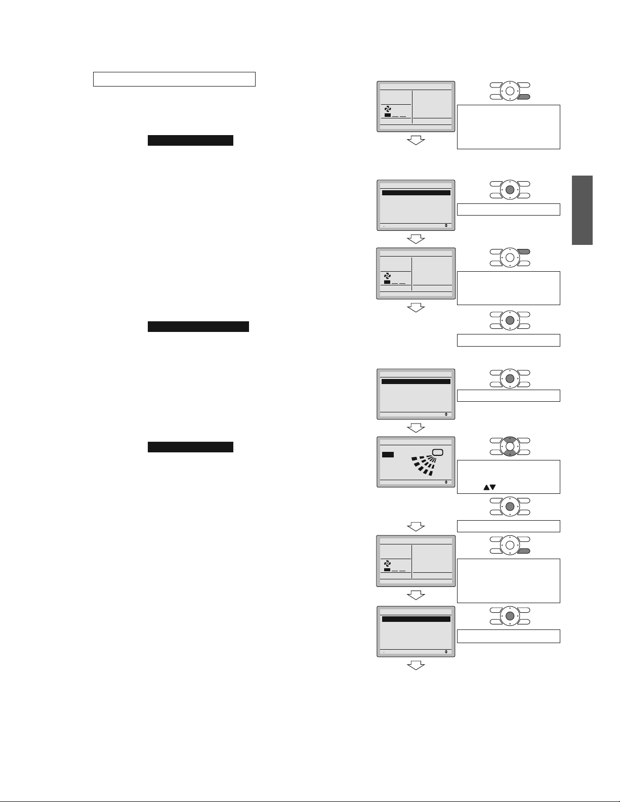
18ŶEspañol
Pantalla básica
1)
2)
Cool
Return %NGCPVJGƂNVGT
Set to
Cool
68F
Mantenga pulsado el botón
Cancelar durante 4 segundos
o más durante la iluminación
de la luz de fondo.
2CPVCNNCFGNOGPÖ
de ajustes de
UGTXKEKQ
3)
Setting
1/3
Service Settings
Test Operation
Maintenance Contact
Field Settings
Energy Saving Options
Prohibit Buttons
Min Setpoints Differential
Pulse el botón Menú/OK.
4)
5)
Set temperature
80°F
Cool
Test Operation
Pulse el botón de encendido/
apagado (antes de que
transcurran 10 segundos).
Pulse el botón Menú/OK.
2CPVCNNCFGNOGPÖ
principal
6)
Setting
MainMenu
Air Flow Direction
Ventilation
Schedule
Off Timer
Celsius / Fahrenheit
Maintenance Information
1/2
Pulse el botón Menú/OK.
7)
Setting
Air Flow Direction
Swing
Cambie la dirección del
ƃWLQFGCKTGWUCPFQGN
botón
(arriba/abajo).
Pulse el botón Menú/OK.
8)
Set temperature
80°F
Cool
Test Operation
Mantenga pulsado el botón
Cancelar durante 4 segundos
o más durante la iluminación
de la luz de fondo.
9)
Setting
1/3
Service Settings
Test Operation
Maintenance Contact
Field Settings
Energy Saving Options
Prohibit Buttons
Min Setpoints Differential
Pulse el botón Menú/OK.
Pantalla básica
2CTCGNEQPVTQNTGOQVQFGECDNG
1) #LWUVGGPQRGTCEKÏP(4©1Q%#.14WUCPFQGNEQPVTQN
remoto.
2) /CPVGPICRWNUCFQGNDQVÏP%CPEGNCTFWTCPVG|UGIWPFQU
o más. Se visualiza el menú de ajustes de servicio.
3) Seleccione Operación de prueba en el menú de ajustes
de servicio y pulse el botón Menú/OK. Aparecerá la
RCPVCNNCD½UKEC[UGXKUWCNK\CT½p1RGTCEKÏPFGRTWGDCq
en la parte inferior.
4) Pulse el botón de encendido/apagado antes de que
VTCPUEWTTCP|UGIWPFQU[EQOGP\CT½NCQRGTCEKÏPFG
prueba.
Supervise el funcionamiento de la unidad interior
durante un mínimo de 10 minutos. Durante la operación
de prueba, la unidad interior continuará enfriando/
calentando sin importar el punto de ajuste de la
temperatura ni la temperatura de la habitación.
r En el caso de los procedimientos 3) y 4) mencionados
anteriormente en orden inverso, también podrá
comenzar la operación de prueba.
5) Pulse el botón Menú/OK en la pantalla básica. Se
visualiza el menú principal.
6) Seleccione &KTGEEKÏPFGNƃWLQFGCKTG en el menú
RTKPEKRCN[EQORTWGDGSWGNCFKTGEEKÏPFGNƃWLQFGCKTG
se activa en conformidad con el ajuste.
2CTCNCQRGTCEKÏPFGNCLWUVGFGNCFKTGEEKÏPFGNƃWLQFG
aire, consulte el manual de operación.
7) 7PCXG\EQPƂTOCFCNCQRGTCEKÏPFGNCFKTGEEKÏPFGNƃWLQ
de aire, pulse el botón Menú/OK. Aparece la pantalla
básica.
8) /CPVGPICRWNUCFQGNDQVÏP%CPEGNCTFWTCPVG|UGIWPFQU
o más en la pantalla básica.
Se visualiza el menú de ajustes de servicio.
9) Seleccione Operación de prueba en el menú de ajustes
FGUGTXKEKQ[RWNUGGNDQVÏP/GPÖ1-8QNXGT½CNC
pantalla básica y se llevará a cabo la operación normal.
r La operación de prueba se detendrá automáticamente
transcurridos 15-30 minutos. Para detener la opera-
ción, pulse botón de encendido/apagado.
10) Si el panel de decoración no se ha instalado, apague la
alimentación después de la operación de prueba.
Español
19 ŶEspañol
Operación de ensayo y prueba
2CTCGNEQPVTQNTGOQVQKPCN½ODTKEQ
1) Pulse
MODE
[UGNGEEKQPGNCQRGTCEKÏP(4©1Q%#.14
2) Pulse
/TEST
FQUXGEGUp2TWGDCqUGT½XKUWCNK\CFQ
3) Pulse
ON OFF
antes de que transcurran 10 segundos y comenzará la operación de prueba.
Supervise el funcionamiento de la unidad interior durante un mínimo de 10 minutos. Durante la operación de prueba, la unidad
interior continuará enfriando/calentando sin importar el punto de ajuste de la temperatura ni la temperatura de la habitación.
r
En el caso de los procedimientos 1) y 2) mencionados anteriormente en orden inverso, también podrá comenzar la operación de prueba.
r
La operación de prueba se detendrá automáticamente transcurridos 15 - 30 minutos. Para detener la operación, pulse
ON OFF
.
r Algunas de las funciones no pueden utilizarse en el modo de operación de prueba.
Precauciones
1) Consulte p%ÏOQFKCIPQUVKECTCXGTÉCUq si la unidad no funciona correctamente.
2. 'NGOGPVQUFGRTWGDC
Elementos de prueba Síntoma Comprobar
Las unidades interior y exterior se instalan correctamente.
Caídas, vibraciones, ruido
¿Está completamente instalada la unidad exterior? 5KPFCÍQUFGQRGTCEKÏPQSWGOCFWTC
Sin fugas de gas refrigerante. Función de refrigeración/calefacción incompleta
El gas refrigerante, los tubos de líquido y la extensión de
la manguera de drenaje están aislados térmicamente.
Fugas de agua
La línea de drenaje está correctamente instalada. Fugas de agua
¿Coincide la tensión de suministro de corriente con la
indicada en la placa de características?
5KPFCÍQUFGQRGTCEKÏPQSWGOCFWTC
5QNCOGPVGUGWUCPNQUECDNGUGURGEKƂECFQURCTC
todo el cableado y todos los cables están conectados
correctamente.
5KPFCÍQUFGQRGTCEKÏPQSWGOCFWTC
El sistema está correctamente conectado a tierra. Fuga eléctrica
5GGPEWGPVTCGNVCOCÍQFGNECDNGGPEQPHQTOKFCFEQP
NCUGURGEKƂECEKQPGU!
5KPFCÍQUFGQRGTCEKÏPQSWGOCFWTC
¿Hay algo bloqueando la entrada o salida del aire de
cualquiera de las unidades interior o exterior?
Función de refrigeración/calefacción incompleta
¿Ha anotado la longitud de la tubería refrigerante y la
carga adicional de refrigerante?
La carga de refrigerante en el sistema no está clara
Los tubos y los cables están conectados a los puertos de conexión/
bloques de terminales correspondientes de la unidad conectada.
Sin refrigeración/calefacción
Las válvulas de retención están abiertas. Función de refrigeración/calefacción incompleta
Compruebe que el conector de los cables del panel de
decoración esté bien conectado.
Las lamas no se mueven
La unidad interior recibe correctamente las órdenes del
control remoto inalámbrico.
Sin operación
'NGOGPVQUCEQORTQDCTGPGNOQOGPVQFGNCGPVTGIC
Consulte igualmente las p2TGECWEKQPGUq en la página 3.
Elementos de prueba Comprobar
5GGPEWGPVTCPNCEWDKGTVCFGNCECLCFGECDNGCFQGNÅEVTKEQƂNVTQFGCKTG[TGLKNNCFGUWEEKÏPKPUVCNCFQU!
¿Explicó las operaciones mientras mostraba al cliente el manual de operación?
¿Entregó el manual de operación al cliente?
2WPVQURCTCNCGZRNKECEKÏPFGNCUQRGTCEKQPGU
Los elementos con las marcas #&8'46'0%+#[ 24'%#7%+¯0GPGNOCPWCNFGQRGTCEKÏPUQPGNGOGPVQUSWGRWGFGP
ECWUCTNGUKQPGUEQTRQTCNGU[FCÍQUOCVGTKCNGUCFGO½UFGCHGEVCTCNWUQIGPGTCNFGNRTQFWEVQ2QTNQVCPVQGUPGEGUCTKQSWG
explique completamente los contenidos descritos y solicite a sus clientes que lean el manual de operación.

20ŶEspañol
Nota para el instalador
#UGIÖTGUGFGGZRNKECTCNQUENKGPVGUEÏOQQRGTCTCFGEWCFCOGPVGNCWPKFCFGURGEKCNOGPVGNCNKORKG\CFGNƂNVTQNCQRGTCEKÏPFG
las distintas funciones y el ajuste de la temperatura) solicitándoles realizar las operaciones mientras consultan el manual.
3. %ÏOQFKCIPQUVKECTCXGTÉCU
r Si el aire acondicionado no funciona normalmente después de instalarlo, puede que exista uno de los fallos indicados en la
siguiente tabla.
Pantalla del control remoto de cable Descripción
Sin pantalla
r Corte de energía, error de tensión de alimentación o fase abierta
r Cableado incorrecto (entre las unidades interior y exterior)
r Fallo de montaje de la tarjeta de PC interior
r Cableado del control remoto no conectado
r Fallo del control remoto
r Fusible abierto o disyuntor disparado (unidad exterior)
p%QORTQDCPFQEQPGZKÏP2QTHCXQT
GURGTGq
r Fallo de montaje de la tarjeta de PC interior
r Cableado equivocado (entre las unidades interior y exterior)
* p%QORTQDCPFQEQPGZKÏP2QTHCXQTGURGTGqUGT½XKUWCNK\CFQFWTCPVGWPO½ZKOQFGUGIWPFQUVTCUNCCEVKXCEKÏPFGNCWPKFCF
interior. Esto es normal y no indica un funcionamiento incorrecto.
Diagnóstico con la visualización de la pantalla de cristal líquido del control remoto.
%QPGNEQPVTQNTGOQVQFGECDNG
Si la operación se detiene a causa de una avería, la lámpara de operación parpadeará y se indicará el código de avería en la
pantalla de cristal líquido. En dicho caso, diagnostique los contenidos del fallo consultando el
Historial de errores en el menú de
ajustes de servicio.
2CTCGNEQPVTQNFGITWRQGNPÖOFGWPKFCFUGXKUWCNK\CFGOQFQSWGUGRWGFCKFGPVKƂECTNCWPKFCFKPVGTKQTEQPRTQDNGOCU
%QPGNEQPVTQNTGOQVQKPCN½ODTKEQ
(Consulte igualmente el manual de operación suministrado con el control remoto inalámbrico)
Cuando la operación se detenga debido a averías, la pantalla de la unidad interior parpadeará. En tal caso, diagnostique los
contenidos del fallo con el código de error que encontrará con los siguientes procedimientos.
1) 2WNUGGNDQVÏPFG+052'%%+¯0247'$#&'(70%+10#/+'061p
qUGT½XKUWCNK\CFQ[pqRCTRCFGCT½
2) 2WNUGGNDQVÏPFG%10(+)74#%+¯0&'.#6'/2'4#674#[NQECNKEGGNPÖOFGWPKFCFFGVGPKFC
Número de bips 3 sonidos de bip corto ...............
1 sonido de bip corto .................
1 sonido de bip prolongado .......
Lleve a cabo todas las operaciones siguientes
Realice (3) y (6)
Ningún problema
3) 2WNUGGNDQVÏP5'.'%614&'./1&1&'12'4#%+¯0[NCEKHTCUWRGTKQTFGNEÏFKIQFGGTTQTRCTRCFGCT½
4) %QPVKPÖGRWNUCPFQGNDQVÏPFG%10(+)74#%+¯0&'.#6'/2'4#674#JCUVCSWGGOKVCUQPKFQUFGDKREQTVQ[
localice el código superior.
5) 2WNUGGNDQVÏP5'.'%614&'./1&1&'12'4#%+¯0[NCEKHTCKPHGTKQTFGNEÏFKIQFGGTTQTRCTRCFGCT½
6) %QPVKPÖGRWNUCPFQGNDQVÏPFG%10(+)74#%+¯0&'.#6'/2'4#674#JCUVCSWGGOKVCWPUQPKFQFGDKR
prolongado y localice el código inferior.
rUn sonido de bip prolongado indica el código de error.
Español

21 ŶEspañol
MEMO

22ŶEspañol
Español

Two-dimensional bar code
is a manufacturing code.
3P436085-1
M15B215
(1607)
HT