NEC Display Solutions of America, Inc.
NP4100W Installation Guide
Desktop and Ceiling Mount v 1.0
www.necdisplay.com NP4100W Page 1 of 10
Contents
Product Description, Lens Specs, Screen/Aspect Ratio
Notes and Formulas
Pg 1
Diagrams & Distance Charts; 16:10
Pg 2
16:9
Pg 3
4:3 ___
Pg 4
Lens Shift Adjustable Range
Pg 5
Tilt Capabilities
Pg 6
Cabinet Dimensions
Pg 7
Lens Dimensions
Pg 8
Ceiling Mount Dimensions
Pg 9
Input Panel and Control Codes
Pg 10
Product Description
Type: 1 chip DLP Projector Dimensions: 19.88” (W) x 8.23” (H) x15.16” (D)
0.65 DMD Weight: 38.6 lbs
Resolution: 1280 x 800 (16:10) / 1066 x 800 (4:3) Brightness: 5500 ANSI Lumens
Powered: Lens Shift, Horizontal & Vertical /Zoom/ Focus BTU’s: 2425 BTU/hour
Fan Noise: 38 dB / 34dB @ 1 meter Power Consumption: 710W (max)
Network Ready
Lens Specifications
NP06FL: Throw Ratio: ~ 0.77:1 Focal Length: 11.4mm NP09ZL: Throw Ratio: ~2.22 - 4.43:1 Focal Length: 32.0 – 63.0mm
Screen Sizes: 50”-200” F/#:2.0 Screen Sizes: 40” - 500” F/#:2.1 – 2.9
NP07ZL: Throw Ratio: ~1.33 - 1.79:1 Focal Length: 19.3 - 25.8mm NP10ZL: Throw Ratio: 4.43 -8.3:1 Focal Length: 63.5 – 117.4mm
Screen Sizes: 40” - 500” F/#:1.8 – 2.3 Screen Sizes: 40” - 500” F/#:2.2 – 3.1
NP08ZL: Throw Ratio: ~1.78 - 2.35:1 Focal Length: 26.0 - 34.0mm
Screen Sizes: 40” – 500 ” F/#:1.7 – 1.9
Screen/Aspect Ratio
Both 4:3 and 16:9 screens are fully supported with proper aspect ratio control for both type sources using NEC developed scaling technology. Menu
selections have aspect ratio control for each source type.
Notes
For screen sizes not indicated on the projection tables, use the formulas below.
If the figures on the tables do not match the results of formulas, use the figures in the table.
All calculations are based on 4:3 aspect ratio.
Distances are in inches, for millimeters multiply by 25.4.
Distances may vary 5%.
Formulas
The Projection Formulas use the image width for calculation. Image width is the same for all aspect ratios, only vertical image size varies. For proper
projector placement, determine the image width for a desired screen size. Use the Screen Formulas below to calculate all screen dimensions. Plug in
the image width for “W” in the Projection Formulas.
Refer to the diagrams and charts for popular screen sizes on page 2, 3 and 4:
Projection Formulas:
Definitions:
NP06FL: C = 0.817W – 1.54 W = Image Width
NP07ZL: C(Wide) = 1.379W – 1.952 --------- C(Tele) = 1.854W – 1.809 H = Image Height (size)
NP08ZL: C(Wide) = 1.844W – 2.362 --------- C(Tele) = 2.435W – 2.461 C = Throw distance
NP09ZL: C(Wide) = 2.328W – 4.147 --------- C(Tele) = 4.639W – 4.175
NP10ZL: C(Wide) = 4.580W – 5.415 --------- C(Tele) = 8.603W – 5.352 16:9 Screen Formulas:
W = H x 16/9
16:10 Screen Formulas:
H = W x 9/16
W = H x 16/10 Diagonal = W x 18.358/16
H = W x 10/16
Diagonal = W x 18.867/16 4:3 Screen Formulas:
W = H x 4/3
Note: Tilting the front of the projector from level up or down by H = W x 3/4
more than 45° could reduce lamp life up to 20%. Screen Diagonal = W x 5/4
NEC Display Solutions of America, Inc.
NP4100W Installation Guide
Desktop and Ceiling Mount v 1.0
www.necdisplay.com NP4100W Page 2 of 10
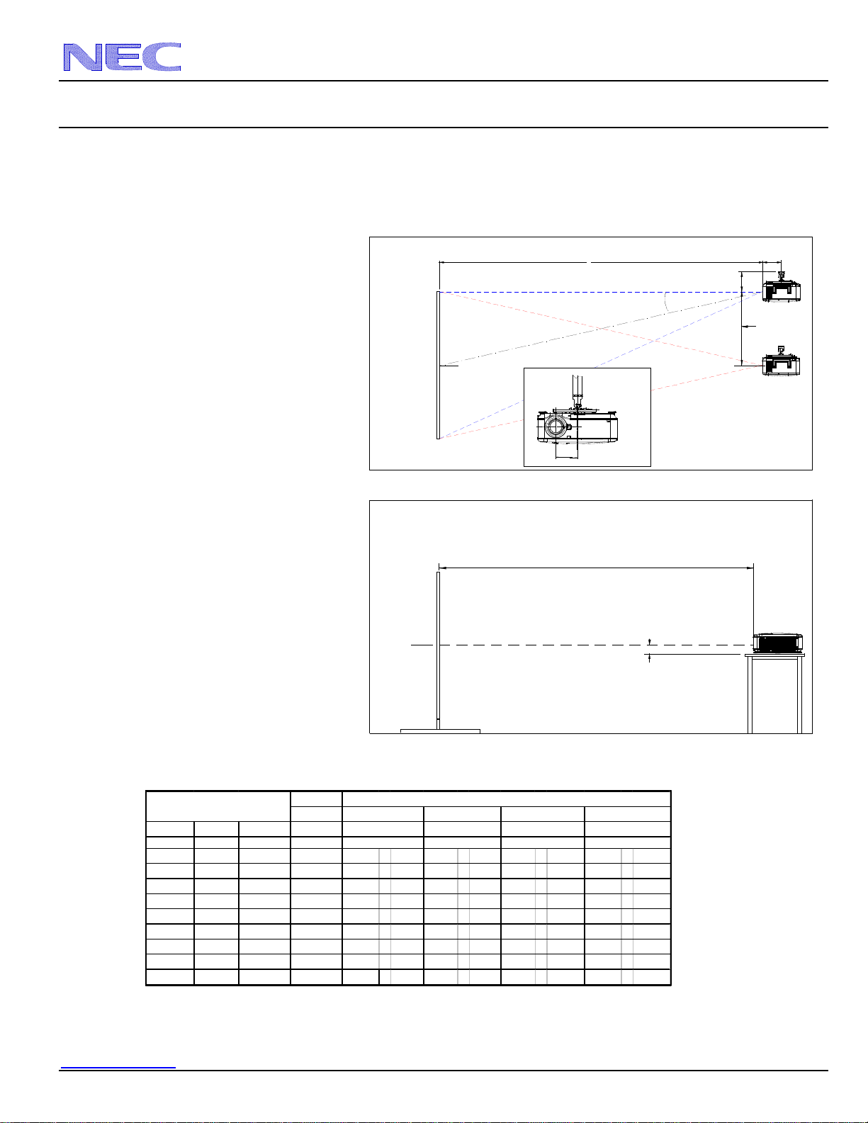
Projection Distance and Screen Size for Ceiling Mount
The following shows the proper relative positions of the projector and screen. Refer to the table to determine the position of installation.
Distances are in inches. For millimeters multiply by 25.4.
Note: To achieve a 16x10 image, you must select 16x10 for each incoming signal in the OSM.
MENU>IMAGE OPTIONS>ASPECT RATIO
Ceiling Mount Installation
Desktop Installation
Note:
Lens shift feature is not available with NP06FL
(rear lens) NP06FL should be used only for
“zero degree” / “no-offset” applications.
Distance Chart for popular 16:10 screens
Note:
For screen sizes not indicated on the projection tables, use the formulas on page 1.
Rear Lens
NP06FL
Diagonal Width(W) Height (H) 0.77:1
inches inches inches inches
67 56.5 35.3 44.62 75.9 - 102.9 101.8 - 135.1 127.4 - 257.9 253.3 - 480.8
76 64 40 50.75 86.3 - 116.8 115.7 - 153.4 144.9 - 292.7 287.7 - 545.3
85 72 45 57.28 97.3 - 131.7 130.4 - 172.8 163.5 - 329.8 324.3 - 614.1
94 80 50 63.82 108.4 - 146.5 145.2 - 192.3 182.1 - 366.9 361.0 - 683.0
109 92 57.5 73.62 124.9 - 168.8 167.3 - 221.5 210.0 - 422.6 415.9 - 786.2
113 96 60 76.89 130.4 - 176.2 174.7 - 231.3 219.4 - 441.2 434.2 - 820.6
123 104 65 83.43 141.4 - 191.0 189.4 - 250.8 238.0 - 478.3 470.9 - 889.5
130 110 69 88.33 149.7 - 202.1 200.5 - 265.4 251.9 - 506.1 498.4 - 941.1
164 139 87 112.02 189.7 - 255.9 254.0 - 336.0 319.5 - 640.6 631.2 - 1190.6
Screen Size (16:10)
Zoom Lenses
4.43 - 8.30:1
NP07ZL NP08ZL NP09ZL NP10ZL
2.22 - 4.43:11.33 - 1.79:1
i
nc
h
es
1.78 - 2.35:1
i
nc
h
es
i
nc
h
es
i
nc
h
es
C
Screen Ctr
Throw Distance
Screen Bottom
3.89"
C
Screen Ctr
Throw Distance
Screen Top
X
7.99"
"Projector Location
X=Distance from lens to mount ctr
NP06FL: X=7.56"
NP07ZL: X=7.56"
NP08ZL: X=7.56"
NP09ZL: X=7.91"
NP10ZL: X=7.56"
Lens Offset From
Mount Pipe
5.32"
Based on Lens Shift"
Lens Shift Range
NEC Display Solutions of America, Inc.
NP4100W Installation Guide
Desktop and Ceiling Mount v 1.0
www.necdisplay.com NP4100W Page 3 of 10
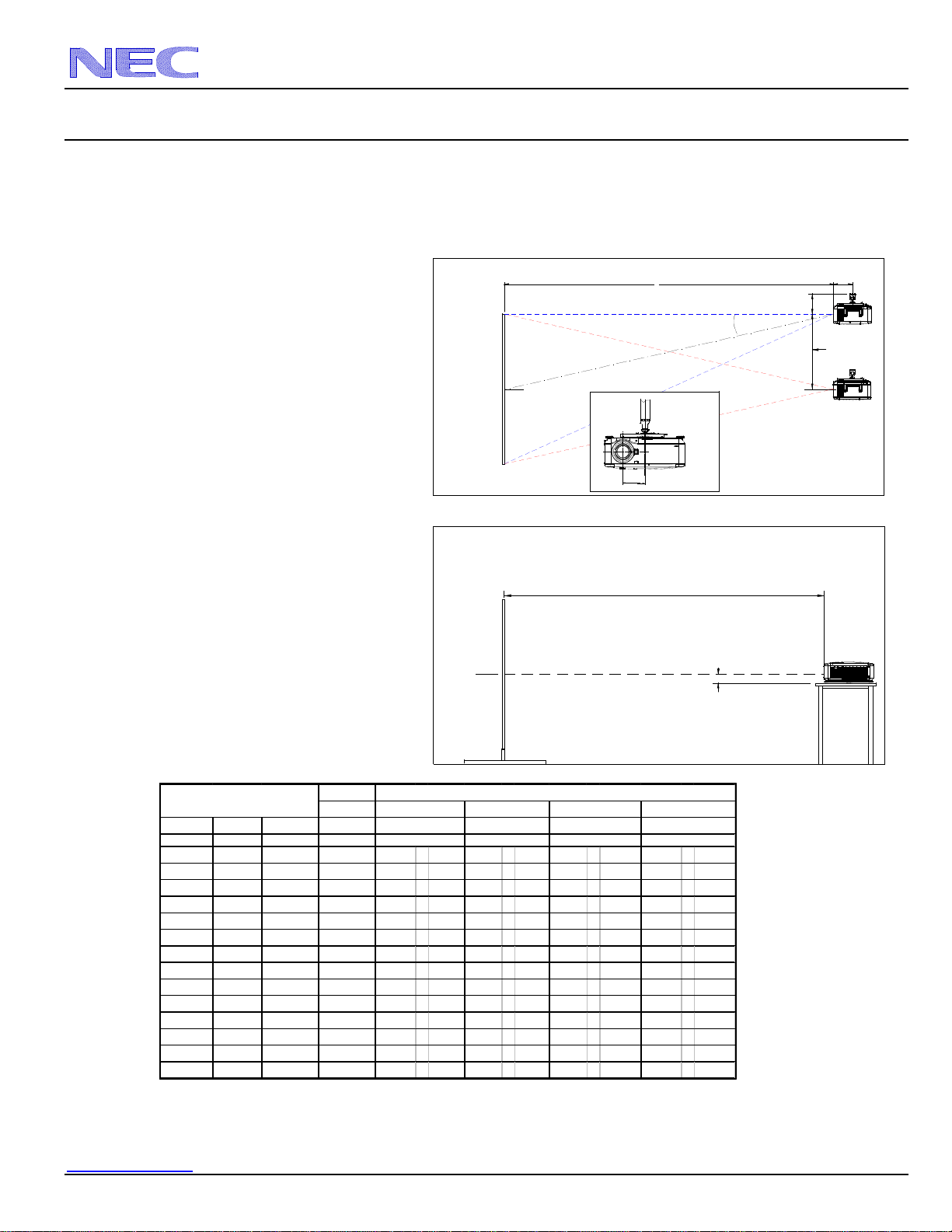
Projection Distance and Screen Size for Ceiling Mount
The following shows the proper relative positions of the projector and screen. Refer to the table to determine the position of installation.
Distances are in inches. For millimeters multiply by 25.4.
Note: To achieve a 16x9 image, you must select 16x9 for each incoming signal in the OSM.
MENU>IMAGE OPTIONS>ASPECT RATIO
Ceiling Mount Installation
Desktop Installation
Note:
Lens shift feature is not available with NP06FL
(rear lens) NP06FL should be used only for
“zero degree” / “no-offset” applications.
Distance Chart for popular 16:9 screens
Note:
For screen sizes not indicated on the projection tables, use the formulas on page 1.
Rear Lens
NP06FL
Diagonal Width(W) Height (H) 0.77:1
inches inches inches inches
92 80 45 64 108 - 147 145 - 192 182 - 367 361 - 683
100 87 49 70 118 - 159 158 - 209 198 - 399 393 - 743
106 92 52 74 125 - 169 167 - 222 210 - 423 416 - 786
110 96 54 77 130 - 176 175 - 231 219 - 441 434 - 821
119 104 58.8 83 141 - 191 189 - 251 238 - 478 471 - 889
123 107 60 86 146 - 197 195 - 258 245 - 492 485 - 915
133 116 65 93 158 - 213 212 - 280 266 - 534 526 - 993
135 118 66 95 161 - 217 215 - 285 271 - 543 535 - 1010
159 139 78 112 190 - 256 254 - 336 319 - 641 631 - 1190
161 140 79 113 191 - 258 256 - 338 322 - 645 636 - 1199
229 200 113 NA 274 - 369 366 - 485 461 - 924 911 - 1715
275 240 135 NA 329 - 443 440 - 582 555 - 1109 1094 - 2059
367 320 180 NA 439 - 591 588 - 777 741 - 1480 1460 - 2748
459 400 225 NA 550 - 740 735 - 972 927 - 1851 1827 - 3436
Screen Size (16:9)
Zoom Lenses
4.43 - 8.30:1
NP07ZL NP08ZL NP09ZL NP10ZL
2.22 - 4.43:11.33 - 1.79:1 1.78 - 2.35:1
i
nc
h
es
i
nc
h
es
i
nc
h
es
i
nc
h
es
C
Screen Ctr
Throw Distance
Screen Bottom
3.89"
C
Screen Ctr
Throw Distance
Screen Top
X
7.99"
"Projector Location
X=Distance from lens to mount ctr
NP06FL: X=7.56"
NP07ZL: X=7.56"
NP08ZL: X=7.56"
NP09ZL: X=7.91"
NP10ZL: X=7.56"
Lens Offset From
Mount Pipe
5.32"
Based on Lens Shift"
Lens Shift Range
NEC Display Solutions of America, Inc.
NP4100W Installation Guide
Desktop and Ceiling Mount v 1.0
www.necdisplay.com NP4100W Page 4 of 10
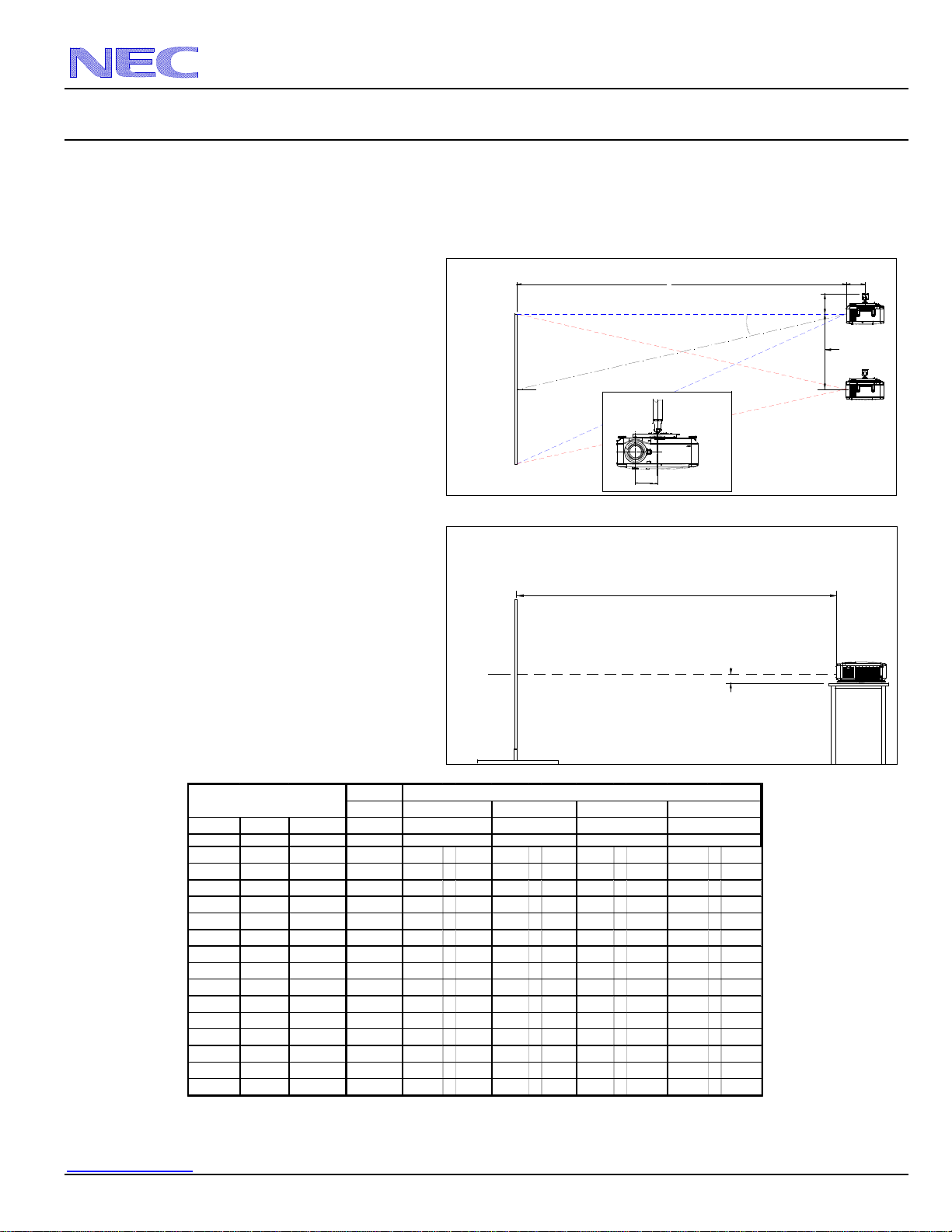
Projection Distance and Screen Size for Ceiling Mount
The following shows the proper relative positions of the projector and screen. Refer to the table to determine the position of installation.
Distances are in inches. For millimeters multiply by 25.4.
Note: To achieve a 4x3 image, you must select 4x3 for each incoming signal in the OSM.
MENU>IMAGE OPTIONS>ASPECT RATIO
Ceiling Mount Installation
Desktop Installation
Note:
Lens shift feature is not available with NP06FL
(rear lens) NP06FL should be used only for
“zero degree” / “no-offset” applications.
Distance Chart for popular 4:3 screens
Note:
For screen sizes not indicated on the projection tables, use the formulas on page 1.
A native (4:3) image will not fill the screen horizontally when using a (16:10) screen.
Rear Lens
NP06FL
Diagonal Width(W) Height (H) 0.77:1
inches inches inches inches
40 32 24 N/A 42.2 57.5 56.6 75.4 70.4 - 144.3 141.1 - 270.0
60 48 36 37.68 64.2 - 87.2 86.2 - 114.4 107.6 - 218.5 214.4 - 407.6
67 53.6 40.2 42.26 71.9 - 97.6 96.5 - 128.0 120.6 - 244.5 240.1 - 455.8
72 57.6 43.2 45.52 77.5 - 105.0 103.9 - 137.8 130.0 - 263.0 258.4 - 490.2
84 67.2 50.4 53.37 90.7 - 122.8 121.6 - 161.2 152.3 - 307.6 302.3 - 572.8
90 72 54 57.29 97.3 - 131.7 130.4 - 172.8 163.5 - 329.8 324.3 - 614.1
100 80 60 63.83 108.4 - 146.5 145.2 - 192.3 182.1 - 366.9 361.0 - 683.0
120 96 72 76.90 130.4 - 176.2 174.7 - 231.3 219.4 - 441.2 434.2 - 820.6
150 120 90 96.51 163.5 - 220.7 218.9 - 289.7 275.2 - 552.5 544.2 - 1027.1
180 144 108 116.11 196.6 - 265.2 263.2 - 348.2 331.1 - 663.8 654.1 - 1233.6
210 168 126 NA 229.7 - 309.7 307.4 - 406.6 387.0 - 775.2 764.0 - 1440.1
240 192 144 NA 262.8 - 354.2 351.7 - 465.0 442.8 - 886.5 873.9 - 1646.6
270 216 162 NA 295.9 - 398.7 395.9 - 523.5 498.7 - 997.9 983.8 - 1853.1
300 240 180 NA 329.0 - 443.1 440.2 - 581.9 554.6 - 1109.2 1093.8 - 2059.6
400 320 240 NA 439.3 - 591.5 587.7 - 776.7 740.8 - 1480.3 1460.2 - 2747.9
inchesinchesinches inches
Screen Size (4:3)
Zoom Lenses
4.43 - 8.30:1
NP07ZL NP08ZL NP09ZL NP10ZL
2.22 - 4.43:11.78 - 2.35:11.33 - 1.79:1
C
Screen Ctr
Throw Distance
Screen Bottom
3.89"
C
Screen Ctr
Throw Distance
Screen Top
X
7.99"
"Projector Location
X=Distance from lens to mount ctr
NP06FL: X=7.56"
NP07ZL: X=7.56"
NP08ZL: X=7.56"
NP09ZL: X=7.91"
NP10ZL: X=7.56"
Lens Offset From
Mount Pipe
5.32"
Based on Lens Shift"
Lens Shift Range
NEC Display Solutions of America, Inc.
NP4100W Installation Guide
Desktop and Ceiling Mount v 1.0
www.necdisplay.com NP4100W Page 5 of 10
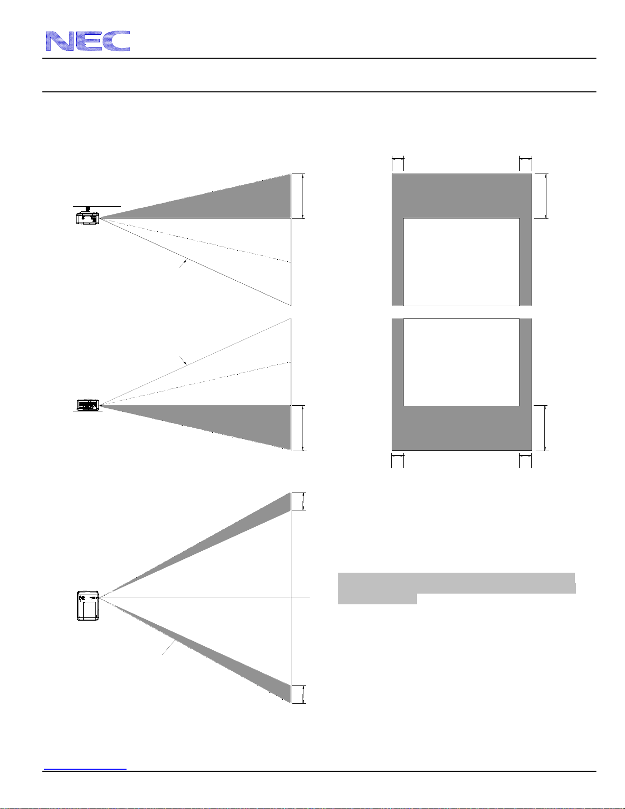
Lens Shift Adjustable Range
Lens Shift Range for Desktop and Ceiling Mount
Application
The diagram below shows the location of the image position
in the lens. The lens can be shifted within the shaded area as
shown using the normal projection position as a starting
point.
Note: Lens shift feature is not available with NP06FL (rear
lens). NP06FL should be used only for “zero degree” / “no-
offset” applications.
Maximum Possible Range
for Standard Lens/NP07ZL/NP08ZL/NP09ZL/NP10ZL:
Up: 0.5H
Right: 0.10W
Left: 0.10W
(W: width of projected image, H: height of projected image)
Normal Position
0.5H
Normal Position
0.5H
Ceiling Front
Vertical
Desktop Front
Vertical
Normal Position
0.1W
Horizontal
0.1W
Normal Projection Position
Normal Projection Position
Ceiling Front
Desktop Front
0.5H
0.5H
0.1W
0.1W
0.1W
0.1W
NEC Display Solutions of America, Inc.
NP4100W Installation Guide
Desktop and Ceiling Mount v 1.0
www.necdisplay.com NP4100W Page 6 of 10
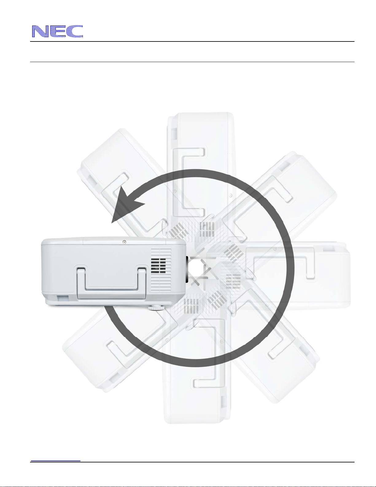
Tilt Free Operation
NEC Display Solutions of America, Inc.
NP4100W Installation Guide
Desktop and Ceiling Mount v 1.0
www.necdisplay.com NP4100W Page 7 of 10
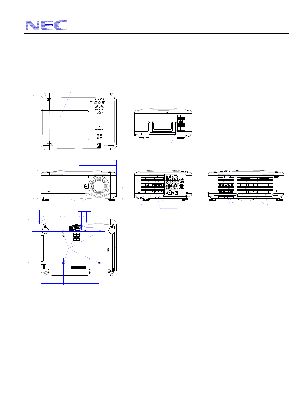
Cabinet Dimensions
The following diagrams show the cabinet dimensions for the NP4100W.
Dimensions are in inches. For millimeters multiply by 25.4.
19.88
5.37
7.76
8.23 15.16
9.45
3.35
11.78
0.47
2.11
5.93
4.925.74
2.14
3.89
4.60
4.90
Air Exhaust
Air IntakeAir Intake
Air Intake
Filter
Filter
Filter
Speaker
Speaker
Lamp & Color Wheel Cover
For Mount
M4*12mm max
NEC Display Solutions of America, Inc.
NP4100W Installation Guide
Desktop and Ceiling Mount v 1.0
www.necdisplay.com NP4100W Page 8 of 10
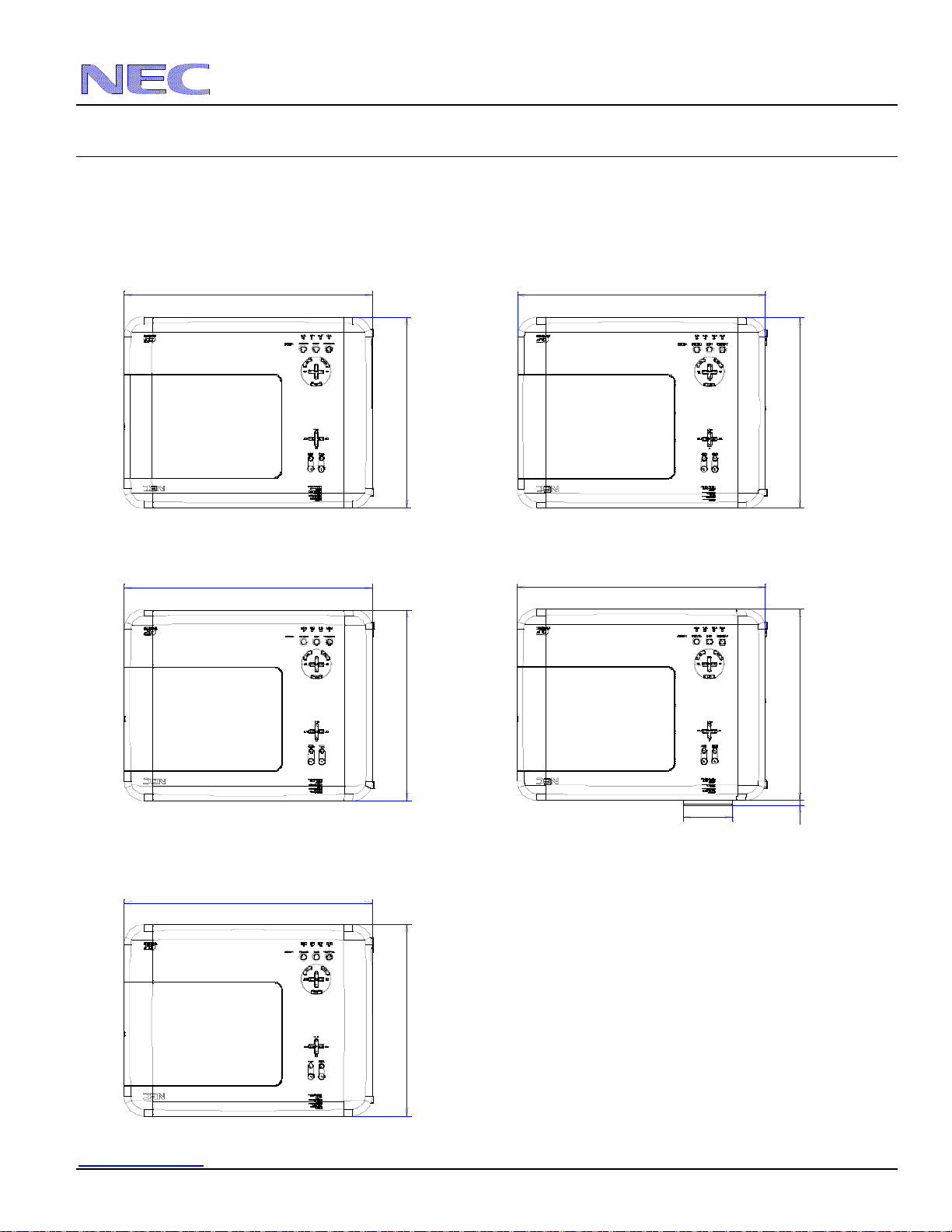
Lens Dimensions
The following drawings show the added dimensions for the optional lenses
Dimensions are in inches. For millimeters multiply by 25.4.
NP06FL
15.16
19.88
NP07ZL
15.16
19.88
NP08ZL
15.16
19.88
NP09ZL
15.16
19.88
.35
3.94
NP10ZL
15.16
19.88
NEC Display Solutions of America, Inc.
NP4100W Installation Guide
Desktop and Ceiling Mount v 1.0
www.necdisplay.com NP4100W Page 9 of 10
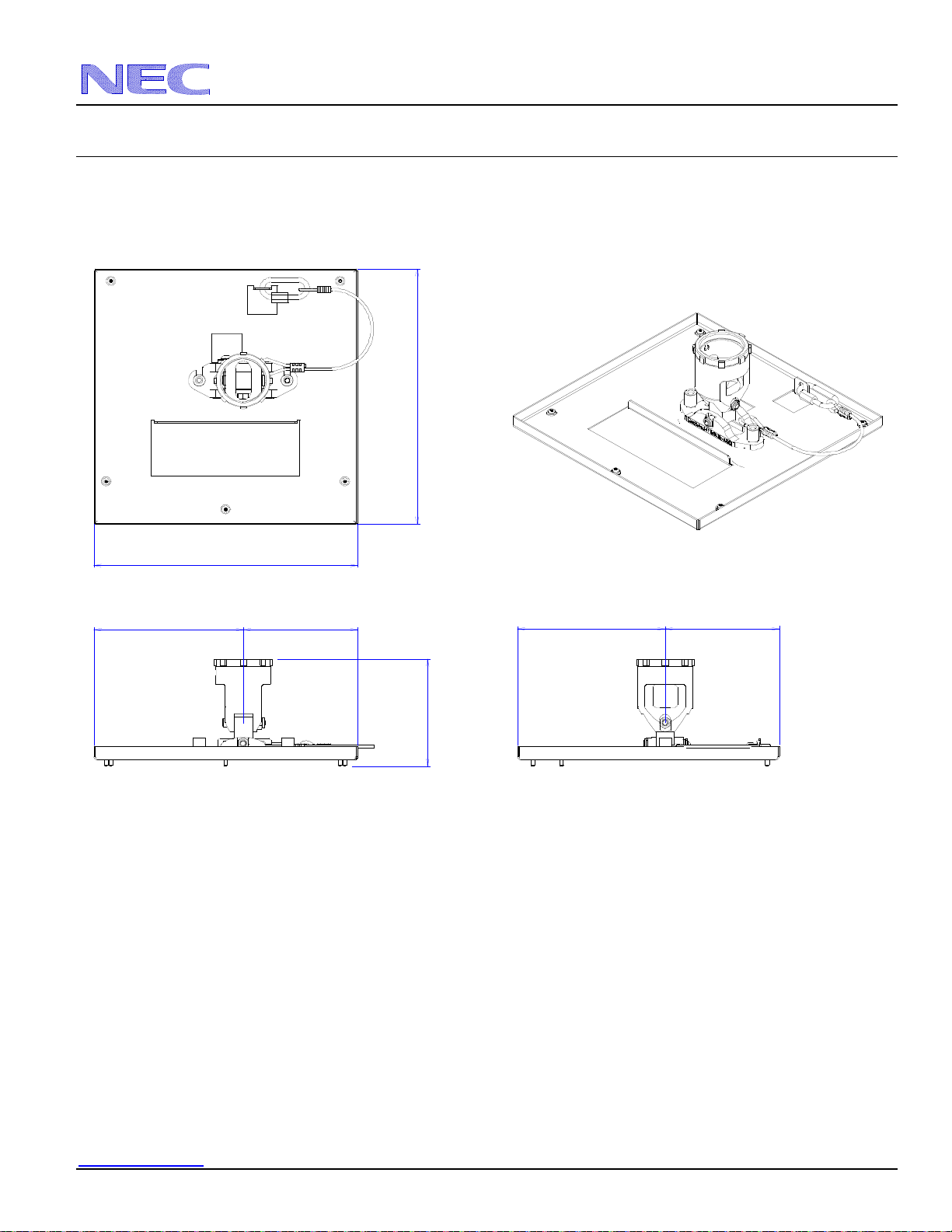
Optional Ceiling Mount Dimensions (Model #: NP4000CM)
The following diagrams show ceiling mount dimensions for the NP4000CM.
Dimensions are in inches. For millimeters multiply by 25.4.
10.78
10.86
6.16
4.70
4.54
6.07 4.71
NEC Display Solutions of America, Inc.
NP4100W Installation Guide
Desktop and Ceiling Mount v 1.0
www.necdisplay.com NP4100W Page 10 of 10
Input Panel
PC Control Codes
Function Code Data
POWER ON 02H 00H 00H 00H 00H 02H
POWER OFF 02H 01H 00H 00H 00H 03H
INPUT SELECT RGB 1 02H 03H 00H 00H 02H 01H 01H 09H
INPUT SELECT RGB 2 02H 03H 00H 00H 02H 01H 02H 0AH
INPUT SELECT RGB 3 02H 03H 00H 00H 02H 01H 1AH 22H
INPUT SELECT COMPONENT 02H 03H 00H 00H 02H 01H 10H 18H
INPUT SELECT VIDEO 02H 03H 00H 00H 02H 01H 06H 0EH
INPUT SELECT S-VIDEO 02H 03H 00H 00H 02H 01H 0BH 13H
PICTURE MUTE ON 02H 10H 00H 00H 00H 12H
PICTURE MUTE OFF 02H 11H 00H 00H 00H 13H
SOUND MUTE ON 02H 12H 00H 00H 00H 14H
SOUND MUTE OFF 02H 13H 00H 00H 00H 15H
ON SCREEN MUTE ON 02H 14H 00H 00H 00H 16H
ON SCREEN MUTE OFF 02H 15H 00H 00H 00H 17H
ASPECT RATIO 4:3 03H 10H 00H 00H 05H 18H 00H 00H 00H 00H 30H
ASPECT RATIO LETTERBOX 03H 10H 00H 00H 05H 18H 00H 00H 01H 00H 31H
ASPECT RATIO 16:9 03H 10H 00H 00H 05H 18H 00H 00H 02H 00H 32H
ASPECT RATIO WIDE ZOOM 03H 10H 00H 00H 05H 18H 00H 00H 03H 00H 33H
ASPECT RATIO AUTO 03H 10H 00H 00H 05H 18H 00H 00H 05H 00H 35H
ASPECT RATIO 16:10 03H 10H 00H 00H 05H 18H 00H 00H 0CH 00H 3CH
ASPECT RATIO 15:9 03H 10H 00H 00H 05H 18H 00H 00H 0DH 00H 3DH
ASPECT RATIO NATIVE 03H 10H 00H 00H 05H 18H 00H 00H 0EH 00H 3EH
AUTO ADJUST 02H 0FH 00H 00H 02H 05H 00H 18H
Cable Connection
Communication Protocol:
Baud Rate: 38400 bps (for cable lengths longer than 20’, it is recommended changing to 9600 bps in setup menu)
Data Length: 8 bits
Parity: No Parity
Stop Bit: One bit
X on/off: None
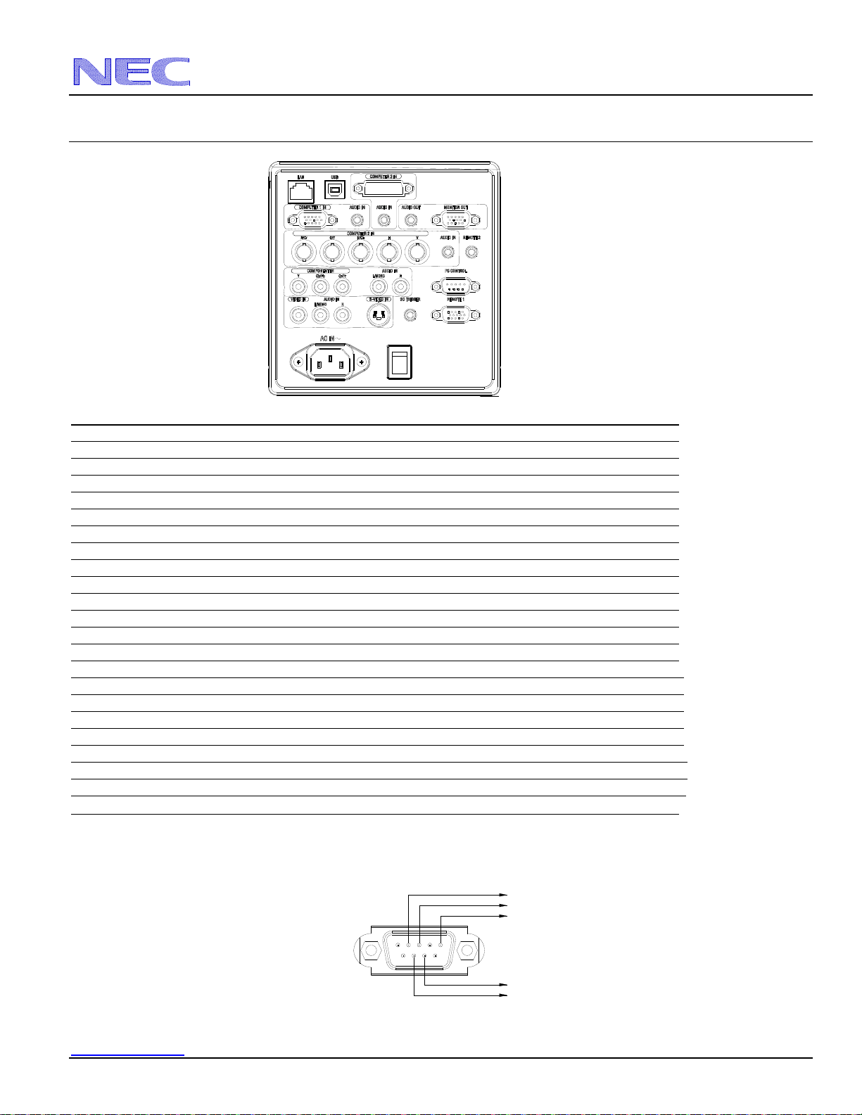
PC Control Connector (D-Sub 9Pin)
Communications: Full duplex
NOTE: Pins 1, 4, 6, and 9 are used inside the projector.
Jumper “Request to send” and “Clear to Send” together on both ends of the cable to simplify cable connection.
12
34
5
678
9
To GND of PC
To RxD of PC
To TxD of PC
To CTS of PC
To RTS of PC