
OWNER MANUAL
MANUALE D’USO
C 5212-64
C 5212-66
C 5212-94
C 5212-96
C 5212-99
C 5215-64
C 5215-66
C 5215-94
C 5215-96
C 5215-99
- ‘COMPACT’ SERIES
LOUDSPEAKERS
- DIFFUSORI ACUSTICI DELLA
SERIE “COMPACT”


TABLE OF CONTENTS
INDICE
ENGLISH
SAFETY
AND OPERATING PRECAUTIONS
DESCRIPTION
INSTALLATION
CONNECTIONS
NOTES ABOUT LOW IMPEDANCE CONNECTIONS
SPECIFICATIONS
C 52122 DIMENSIONS
C 5215 DIMENSIONS
ITALIANO
AVVERTENZE PER LA SICUREZZA
DESCRIZIONE
INSTALLAZIONE
COLLEGAMENTI
NOTE SUI SISTEMI CON CONNESSIONE A BASSA IMPEDENZA
DATI TECNICI
DIMENSIONI C 5212
DIMENSIONI C 5215
4
6
7
10
11
12
13
14
16
18
19
22
23
24
25
26

4
ENGLISH
IMPORTANT NOTES
Before connecting and using this product, please read this instruction manual carefully
and keep it on hand for future reference. This manual is to be considered an integral part
of this product and must accompany it when it changes ownership as a reference for
correct installation and use as well as for the safety precautions.
RCF S.p.A. will not assume any responsibility for the incorrect installation and / or use of
this product.
WARNING: To prevent the risk of re or electric shock, never expose this loudspeaker to
rain or humidity and also dust.
SAFETY AND OPERATING PRECAUTIONS
1. All the precautions, in particular the safety ones, must be read with special attention,
as they provide important information.
2. Loudspeaker lines (amplier outputs) can have a sufciently high voltage to involve
a risk of electrocution: never install or connect this loudspeaker when ampliers are
switched on.
3. Make sure all connections have been made correctly and the loudspeaker input
impedance is suitable for the amplier output.
4. Protect loudspeaker lines from damage; make sure they are positioned in a way that
they cannot be stepped on or crushed by objects.
5. Make sure that no objects or liquids can get into this product, as this may cause a
short circuit.
6. Never attempt to carry out any operations, modications or repairs that are not
expressly described in this manual.
Contact your authorized service centre or qualified personnel should any of the
following occur:
- The loudspeaker does not function (or works in an anomalous way).
- The cable has been damaged.
- Objects or liquids are inside the loudspeaker.
- The loudspeaker has been damaged due to heavy impacts or re.
7. Should the loudspeaker emit any strange odours or smoke, remove it from the line
after having immediately switched the amplier off.
8. Do not connect this product to any equipment or accessories not foreseen.
For suspended installation, only use the dedicated anchoring points and do not try to
hang this loudspeaker by using elements that are unsuitable or not specic for this
purpose.
Also check the suitability of the support surface to which the product is anchored (wall,
ceiling, structure, etc.), and the components used for attachment (screw anchors, screws,
brackets not supplied by RCF etc.), which must guarantee the security of the system /
installation over time, also considering, for example, the mechanical vibrations normally
generated by transducers.
9. RCF S.p.A. strongly recommends this product is only installed by professional qualied
installers (or specialised rms) who can ensure a correct installation and certify it
according to the regulations in force.
The entire audio system must comply with the current standards and regulations
regarding electrical systems.
IMPORTANT
SAFETY PRECAUTIONS

5
ENGLISH
10. Mechanical and electrical factors need to be considered when installing a
professional audio system (in addition to those which are strictly acoustic, such as sound
pressure, angles of coverage, frequency response, etc.).
11. Hearing loss
Exposure to high sound levels can cause permanent hearing loss. The acoustic pressure
level that leads to hearing loss is different from person to person and depends on the
duration of exposure.
To prevent potentially dangerous exposure to high levels of acoustic pressure, anyone
who is exposed to these levels should use adequate protection devices.
When a transducer capable of producing high sound levels is being used, it is necessary
to wear ear plugs or protective earphones.
See the technical specications in the instruction manual for the maximum sound
pressure the loudspeaker is capable of producing.
12. To ensure a correct sound reproduction, loudspeaker phase is to be respected
(loudspeakers are connected respecting the amplier polarity). This is important when
loudspeakers are installed adjacent one another, for instance, in the same room.
13. To prevent inductive effects from causing hum, noise and a bad system working,
loudspeaker lines should not be laid together with other electric cables (mains),
microphone or line level signal cables connected to amplier inputs.
14. The loudspeaker cable shall have wires (twisted, if possible, to reduce inductive
effects due to surrounding electro-magnetic elds) with a suitable section and a sufcient
electrical insulation. Refer to local regulations since there may be additional requirements
about cable characteristics.
15. Do NOT connect the loudspeaker low impedance (8 Ω) input to 70 / 100 V constant
voltage lines.
16. Install this loudspeaker far from any heat source.
17. Do not overload the loudspeaker with too much power.
18. Do not use solvents, alcohol, benzene or other volatile substances for cleaning the
external parts of this product. Use a dry cloth.
6
ENGLISH
RCF S.P.A. THANKS YOU FOR PURCHASING THIS PRODUCT, WHICH HAS BEEN
DESIGNED TO GUARANTEE RELIABILITY AND HIGH PERFORMANCE.
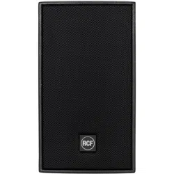
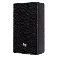
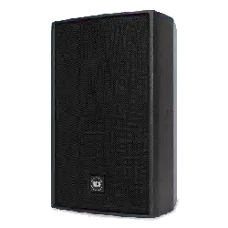
DESCRIPTION
The new ‘Compact’ series includes a wide range of high quality 2-way passive
Design’ technology, that helps guarantee an optimal transition between the high
frequency horn polar pattern and the low frequency woofer directivity.
The horn can be rotated, allowing to install the loudspeaker either vertically or horizontally.
This manual covers 2 models of the new series:
- C 5212 two-way loudspeaker, 12” woofer (3” voice coil) and 1.4” driver (2.5” voice coil)
- C 5215 two-way loudspeaker, 15” woofer (3” voice coil) and 1.4” driver (2.5” voice coil)
The C 5212 and C 5215 models are available with 5 different horn dispersions, indicated
by 5 different suffixes:
- C 5212-64, C 5212 having 60° (horizontal) x 40° (vertical) dispersion
- C 5212-66, C 5212 having 60° (horizontal) x 60° (vertical) dispersion
- C 5212-94, C 5212 having 90° (horizontal) x 40° (vertical) dispersion
- C 5212-96, C 5212 having 90° (horizontal) x 60° (vertical) dispersion
- C 5212-99, C 5212 having 90° (horizontal) x 90° (vertical) dispersion
- C 5215-64, C 5215 having 60° (horizontal) x 40° (vertical) dispersion
- C 5215-66, C 5215 having 60° (horizontal) x 60° (vertical) dispersion
- C 5215-94, C 5215 having 90° (horizontal) x 40° (vertical) dispersion
- C 5215-96, C 5215 having 90° (horizontal) x 60° (vertical) dispersion
- C 5215-99, C 5215 having 90° (horizontal) x 90° (vertical) dispersion.
All models are carefully assembled in Italy (in our main factory) and include RCF woofers
and drivers that are the best of the most recent technology about transducers.
All loudspeakers are equipped with a high power handling ‘Low Impedance
Compensated Crossover’, having an electronic protection for the driver.
It is also possible to choose the “bi-amp” mode (an amplifier for low frequencies and
another one for high frequencies) by using an external crossover.
All cabinets are made of Baltic birch plywood (heavy duty painted) and allow different
installation options.
The steel front grilles are protected with a robust double mesh polyester clothing.
The front RCF logo is easily rotatable.
All models are equipped with top and bottom ‘Multiplates’ for either wall or suspended
mounting with chains.
Installation points are available on rear panels.
All models have two Neutrik Speakon NL4 connectors (audio input and parallel link output).
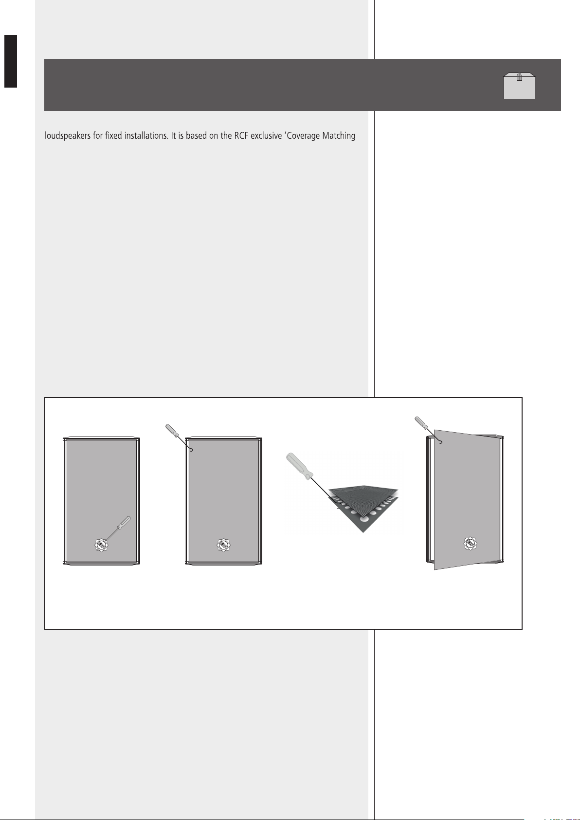
HOW TO REMOVE THE GRILLE TO HAVE ACCESS TO THE HORN
Rotate the RCF Logo 45°
to show the two screw
heads, then remove the
screws.
Using a hook, pass
through the foam layer
and try to locate a hole on
a side of the metal grille
Once the hook is hanged to
the metal grille, pull gently.
The grille should now lift
and can be removed
Notice the metal grille is located under
a foam layer.
THE HOOK MUST BE HANGED TO THE
METAL GRILLE.
DO NOT PULL IF THE HOOK IS
HANGED TO THE FOAM LAYER.
7
ENGLISH
INSTALLATION
Loudspeakers are to be install by qualied personnel, respecting all safety standards.
Loudspeakers are to be installed securely.
Make sure the support structure (walls / ceilings) has the necessary mechanical
characteristics for the loudspeaker weight, without the risk of a fall that could damage
things or cause an injury.
Us
e attachments elements suitable for walls / ceilings (e.g. wall plugs for bricks, concrete, etc.).
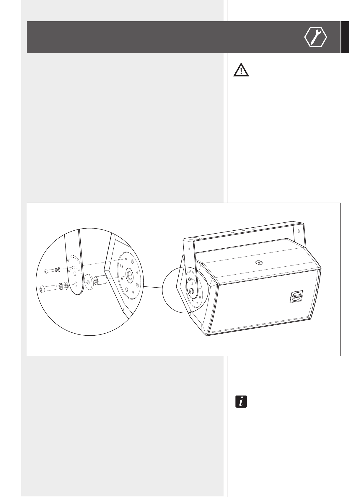
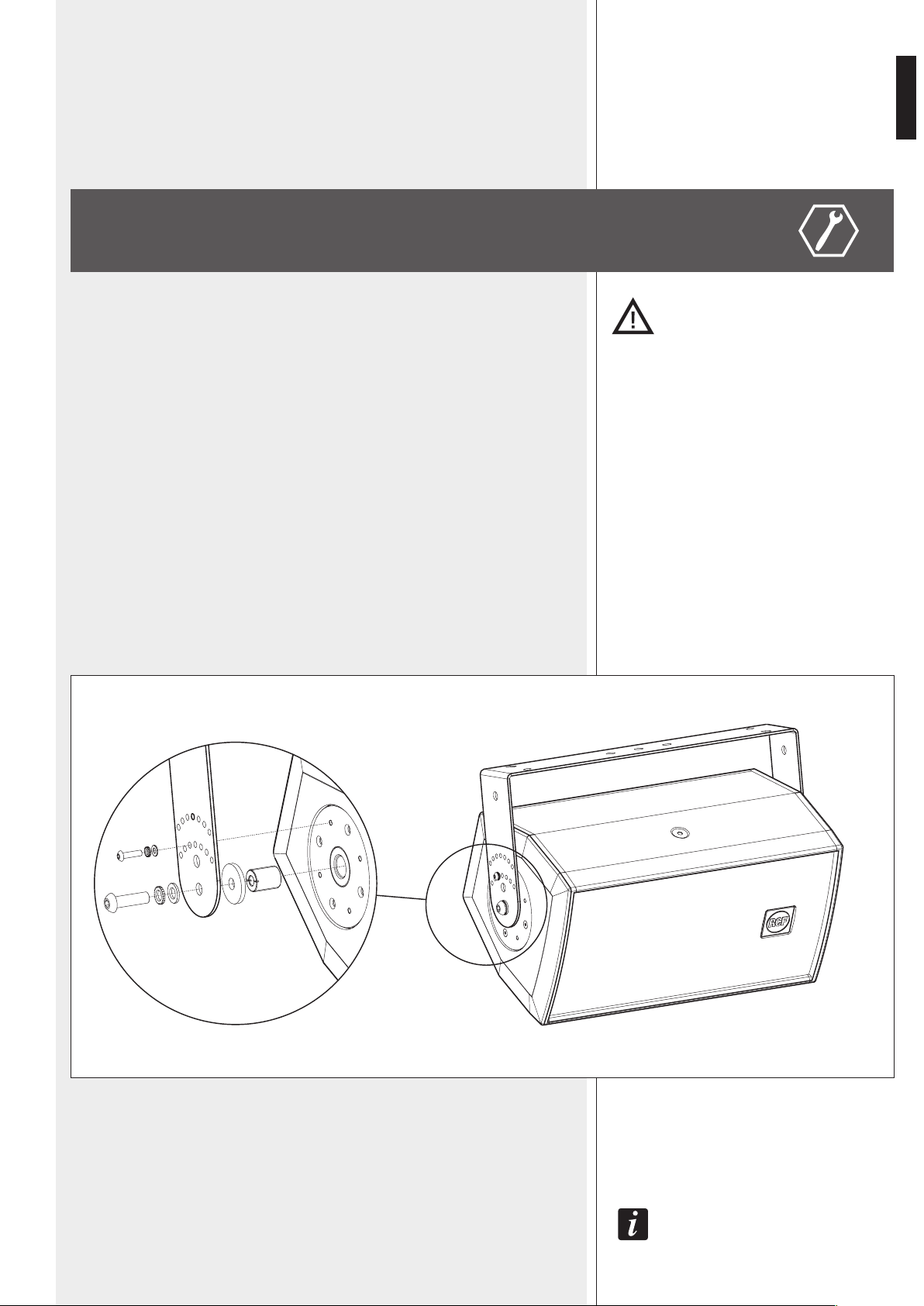
a) HORIZONTAL MOUNTING WITH U BRACKET
NECESSARY OPTIONAL ACCESSORY:
- AC NC12 H-BR (for the C 5212-64, C 5212-66, C 5212-94, C 5212-96,
C 5212-99 models)
- AC NC15 H-BR (for the C 5215-64, C 5215-66, C 5215-94, C 5215-96,
C 5215-99 models).
Fix the U bracket to the wall / ceiling through at least 4 lateral wall plugs (max. M8) plus a
central one (max. M10).
Mount the U bracket to the loudspeaker by tightening the two M10x35 bolts into the two
central holes of the multiplates, as shown in the gure below.
As an alternative, it is possible to install the loudspeaker a bit less prominent, tanks to the U
bracket inner holes. Before tightening the two M10 bolts, adjust the loudspeaker vertical tilt
and then x it through two M5x20 bolts into one of the 7 small holes of the U bracket.
Note: do Not tilt the loudspeaker upwards!
iNstead of simple m10 bolts, it is possible to use the iNcluded kNobs (haviNg m10 bolts).

8
ENGLISH
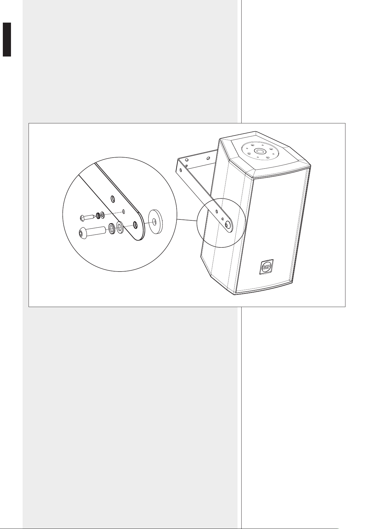
b) VERTICAL MOUNTING WITH U BRACKET
NECESSARY OPTIONAL ACCESSORY:
-
AC NC12 V-BR
(for the C 5212-64, C 5212-66, C 5212-94, C 5212-96, C 5212-99 models)
- AC NC15 V-BR
(for the C 5215-64, C 5215-66, C 5215-94, C 5215-96, C 5215-99 models).
Fix the U bracket to the wall / ceiling through at least 4 lateral wall plugs (max. M8) plus
a central one (max. M10).
Mount the U bracket to the loudspeaker by tightening the two M10x35 bolts into the
two lateral holes of the loudspeaker, as shown in the figure below.
As an alternative, it is possible to install the loudspeaker a bit less prominent, tanks to
the U bracket inner holes.
Before tightening the two M10 bolts, adjust the loudspeaker vertical tilt and then x it
through two M4.2x22 self-threading screws (passing through the small hole of the U
bracket) directly into the loudspeaker cabinet wood.
Note: do NOT tilt the loudspeaker upwards!
Instead of simple M10 bolts, it is possible to use the included knobs (having M10 bolts).

9
ENGLISH
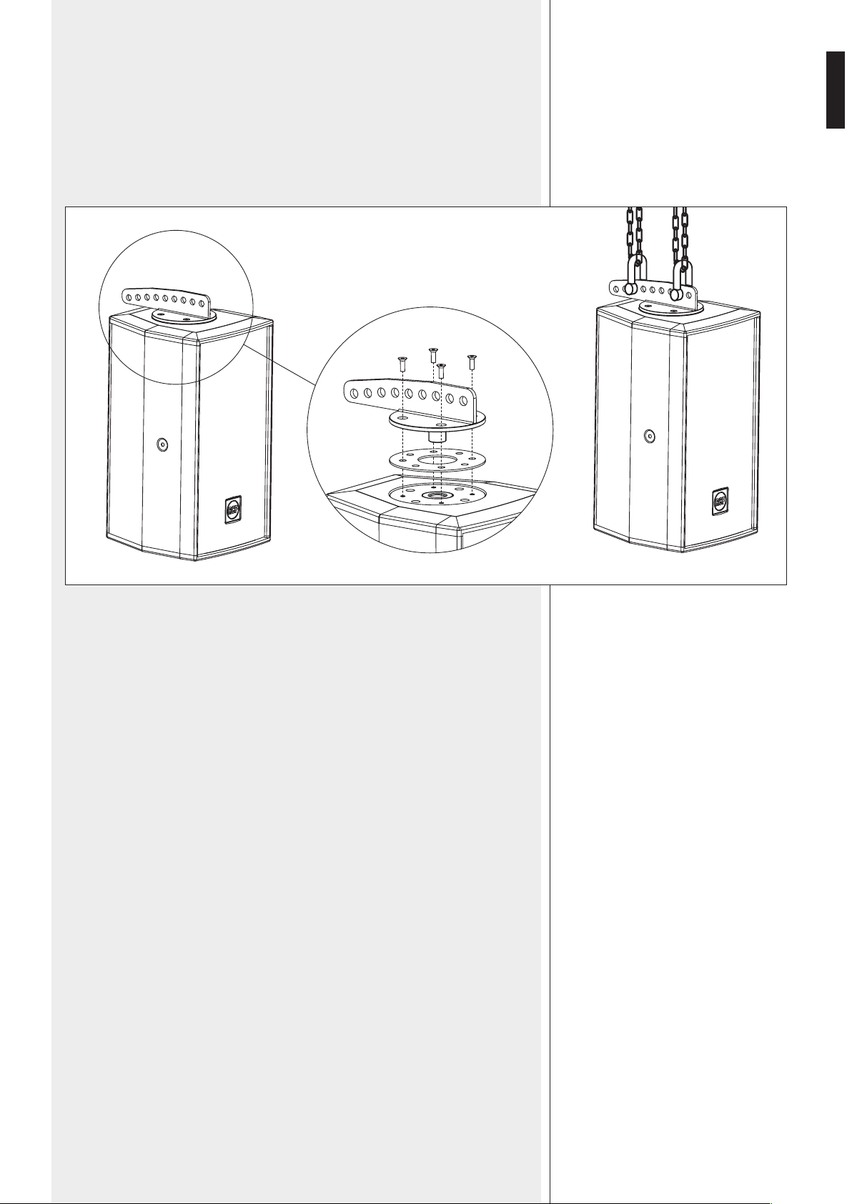
c) SUSPENDED MOUNTING WITH A DEDICATED ACCESSORY
NECESSARY OPTIONAL ACCESSORY: AC NC-FB2
The AC NC-FB2 accessory is a bracket with holes that allows the loudspeaker suspension
with two M10 D-shackles and chains (not included).
Fix the AC NC-FB2 accessory to the loudspeaker top multiplate through four M5 at
head, as shown in the gure below.

10
ENGLISH
CONNECTIONS
WARNING: loudspeaker connections should be only made by qualied and experienced
personnel having the technical know-how or sufcient specic instructions (to ensure
that connections are made correctly) in order to prevent any electrical danger.
To prevent any risk of electric shock, do not connect loudspeakers when the amplier is
switched on.
Before turning the system on, check all connections and make sure there are
no accidental short circuits.
The entire sound system shall be designed and installed in compliance with
the current local laws and regulations regarding electrical systems.
‘Compact’ series loudspeakers are designed for indoor use only. If installed
outdoor, loudspeakers shall be protected against water.
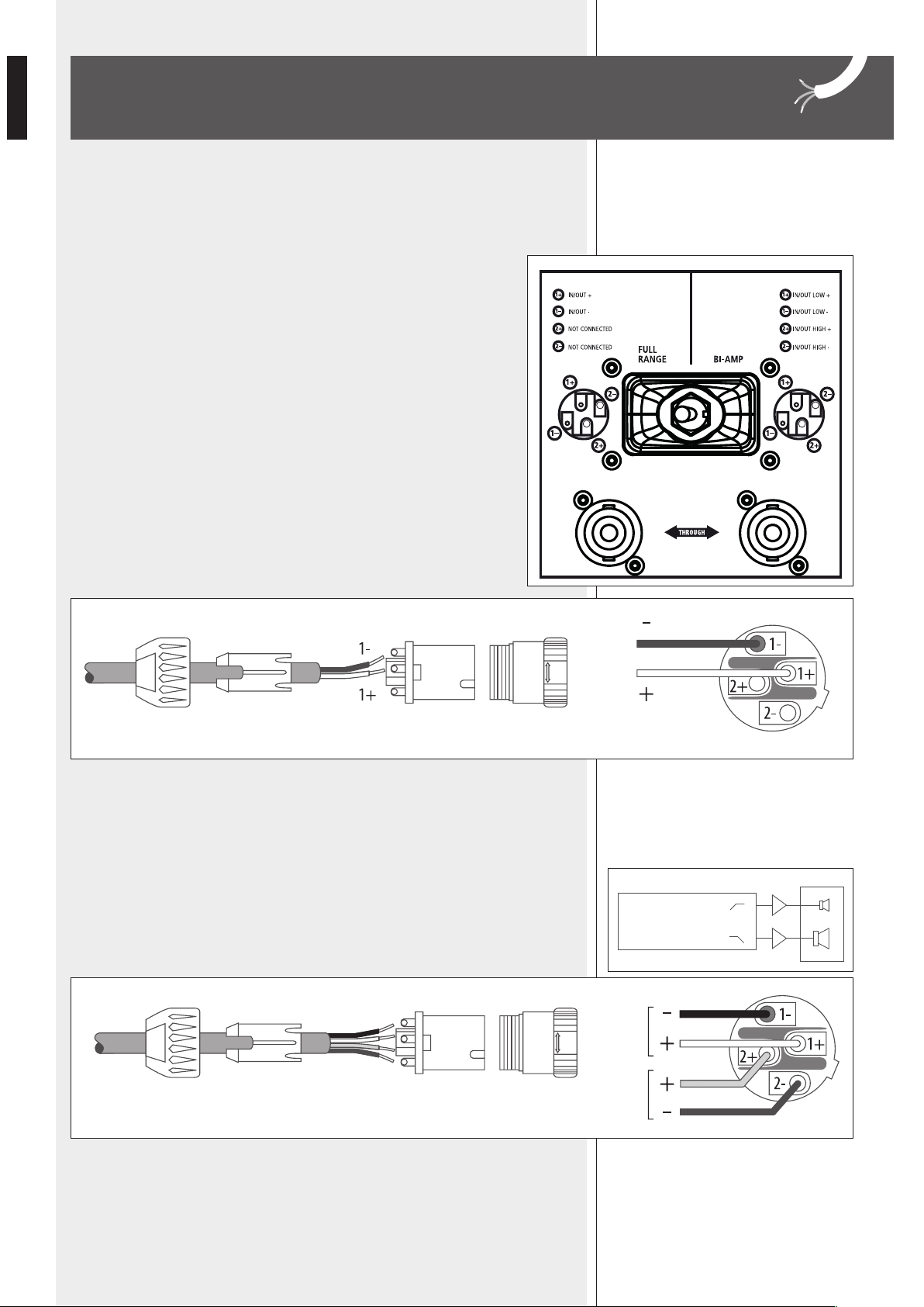
On each rear panel:
- A switch to select either ‘FULL RANGE’ (one amplier and use of the internal
crossover) or ‘BI-AMP’ (bi-amplication and external crossover)
- 2 sockets (input and output, linked in parallel) for ‘Neutrik Speakon NL4’
(4-pole) plugs.
‘FULL RANGE’ MODE
The impedance value of each loudspeaker is 8 Ω.
Connect the positive wire (amplier ‘+’ output) to the pin 1+ of the SPEAKON connector.
Connect the negative wire (amplier ‘–’ output) to the pin 1– of the SPEAKON connector.
The pins 2+ and 2– are not used.
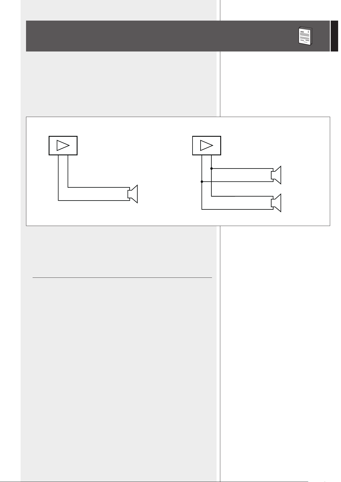
‘BI-AMP’ MODE
Two ampliers are necessary (one for low frequencies, one for high frequencies) and an
external crossover.
See in the specication table the impedance of each way, the handling power and the
suggest crossover frequency.
Connections:
- Low frequency amplier + output to the pin 1+ of the SPEAKON connector
- Low frequency amplier – output to the pin 1– of the SPEAKON connector
- High frequency amplier + output to the pin 2+ of the SPEAKON connector
- High frequency amplier – output to the pin 2– of the SPEAKON connector.
LOW
HIGH
CROSSOVER
AMP.
AMP.
11
ENGLISH
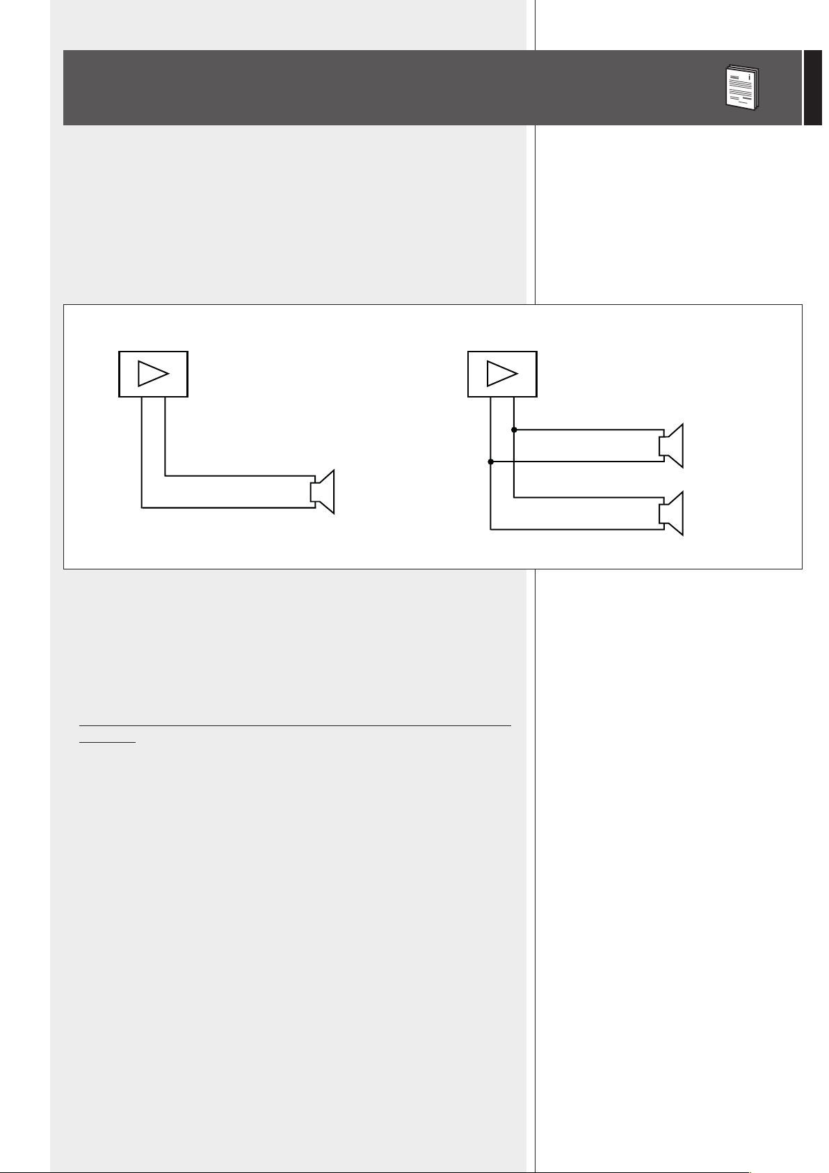
NOTES ABOUT LOW IMPEDANCE CONNECTIONS
- The total loudspeaker impedance must not be lower than the amplier output
impedance. Note: a loudspeaker total impedance equal to the amplier output one
permits to get the maximum deliverable power (but an higher loudspeaker impedance
entails less power).
- The total loudspeaker power shall be adequate for the maximum deliverable power of
the amplier.
- The loudspeaker line shall be short (for long distances, it may be necessary to use cables
with large cross-section wires).
- Always use cables having wires with an adequate cross-section, considering the cable
length and the total loudspeaker power.
- Loudspeaker lines must be kept separated from the mains cables, microphone cables or
others, in order to avoid inductive phenomena may cause hum or noises.
- Use loudspeaker cables with twisted wires to reduce hum caused by inductive effects
due to coupling with electromagnetic elds.
- Do NOT connect the low impedance input directly to 70 / 100 V constant voltage lines.
- +
TOTAL IMPEDANCE: 4 Ω
8 Ω
8 Ω
+
+
- +
TOTAL IMPEDANCE: 8 Ω
8 Ω
+
12
ENGLISH
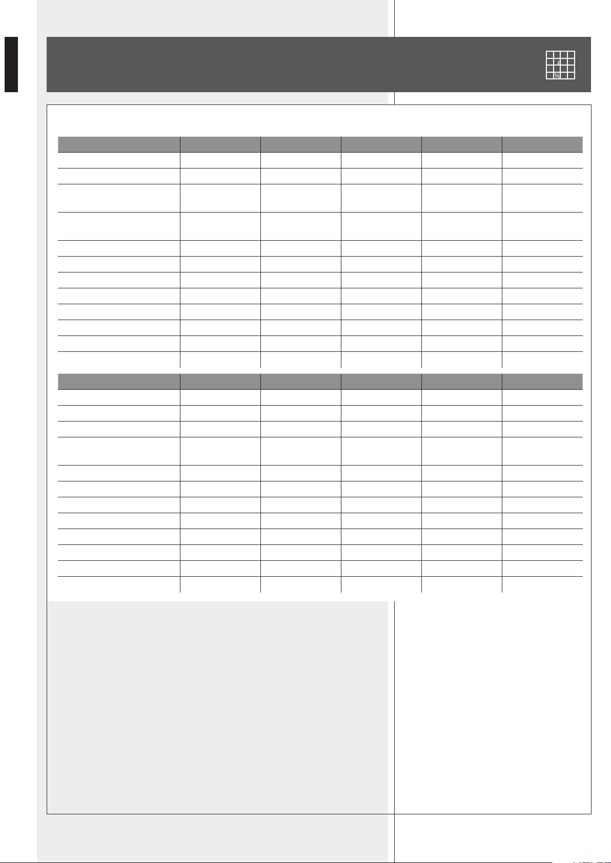
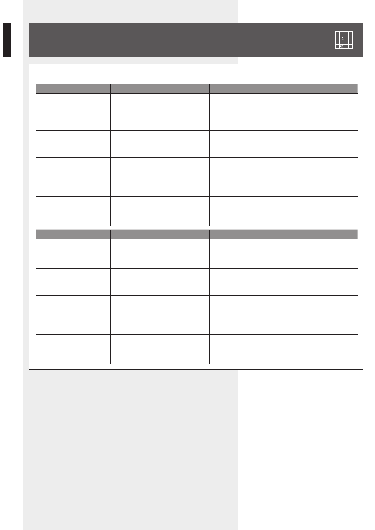
SPECIFICATIONS
CABINET: birch plywood COLOUR: black
MODEL C 5212-64 C 5212-66 C 5212-94 C 5212-96 C 5212-99
IMPEDANCE (‘full range’) 8 Ω 8 Ω 8 Ω 8 Ω 8 Ω
RMS POWER, (“full-range”) 500 W 500 W 500 W 500 W 500 W
IMPEDANCES (‘bi-amp’)
8 Ω (LF)
8 Ω (HF)
8 Ω (LF)
8 Ω (HF)
8 Ω (LF)
8 Ω (HF)
8 Ω (LF)
8 Ω (HF)
8 Ω (LF)
8 Ω (HF)
AES POWERS (‘bi-amp’)
400 W (LF)
100 W (HF)
400 W (LF)
100 W (HF)
400 W (LF)
100 W (HF)
400 W (LF)
100 W (HF)
400 W (LF)
100 W (HF)
CROSSOVER FREQUENCY 1.2 kHz 1.2 kHz 1.2 kHz 1.2 kHz 1.2 kHz
FREQUENCY RESPONSE (-10 dB) 60 Hz ÷ 20 kHz 60 Hz ÷ 20 kHz 60 Hz ÷ 20 kHz 60 Hz ÷ 20 kHz 60 Hz ÷ 20 kHz
SENSITIVITY (1 W / 1 m) 98 dB 98 dB 98 dB 98 dB 98 dB
SPL (1 m) 125 dB (500 W) 125 dB (500 W) 125 dB (500 W) 125 dB (500 W) 125 dB (500 W)
WOOFER 12” (3” v.c.) 12” (3” v.c.) 12” (3” v.c.) 12” (3” v.c.) 12” (3” v.c.)
DRIVER 1.4” (2.5” v.c.) 1.4” (2.5” v.c.) 1.4” (2.5” v.c.) 1.4” (2.5” v.c.) 1.4” (2.5” v.c.)
DISPERSION (hor. x vert.) 60° x 40° 60° x 60° 90° x 40° 90° x 60° 90° x 90°
NET WEIGHT 29 kg 29 kg 29 kg 29 kg 29 kg
MODEL C 5215-64 C 5215-66 C 5215-94 C 5215-96 C 5215-99
IMPEDANCE (‘full range’) 8 Ω 8 Ω 8 Ω 8 Ω 8 Ω
RMS POWER, (“full-range”) 500 W 500 W 500 W 500 W 500 W
IMPEDANCES (‘bi-amp’) 8 Ω(LF)-8 Ω(HF) 8 Ω(LF)-8 Ω(HF) 8 Ω(LF)-8 Ω(HF) 8 Ω(LF)-8 Ω(HF) 8 Ω(LF)-8 Ω(HF)
AES POWERS (‘bi-amp’)
400 W (LF)
100 W (HF)
400 W (LF)
100 W (HF)
400 W (LF)
100 W (HF)
400 W (LF)
100 W (HF)
400 W (LF)
100 W (HF)
CROSSOVER FREQUENCY 1.2 kHz 1.2 kHz 1.2 kHz 1.2 kHz 1.2 kHz
FREQUENCY RESPONSE (-10 dB) 55 Hz ÷ 20 kHz 55 Hz ÷ 20 kHz 55 Hz ÷ 20 kHz 55 Hz ÷ 20 kHz 55 Hz ÷ 20 kHz
SENSITIVITY (1 W / 1 m) 99 dB 99 dB 99 dB 99 dB 99 dB
SPL (1 m) 126 dB (500W) 126 dB (500W) 126 dB (500W) 126 dB (500W) 126 dB (500W)
WOOFER 15” (3” v.c.) 15” (3” v.c.) 15” (3” v.c.) 15” (3” v.c.) 15” (3” v.c.)
DRIVER 1.4” (2.5” v.c.) 1.4” (2.5” v.c.) 1.4” (2.5” v.c.) 1.4” (2.5” v.c.) 1.4” (2.5” v.c.)
DISPERSION (hor. x vert.) 60° x 40° 60° x 60° 90° x 40° 90° x 60° 90° x 90°
NET WEIGHT 34.8 kg 34.8 kg 34.8 kg 34.8 kg 34.8 kg
13
ENGLISH
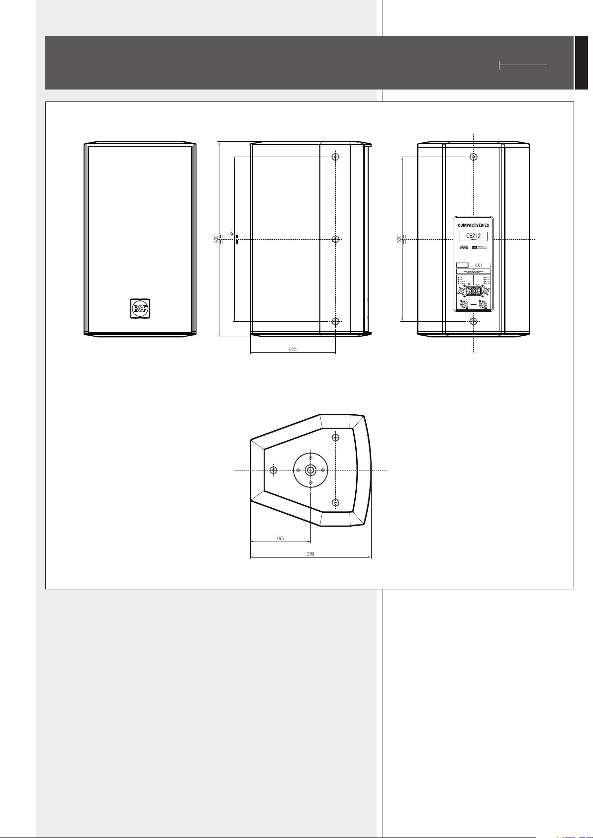
C 5212 DIMENSIONS
mm
14
ENGLISH
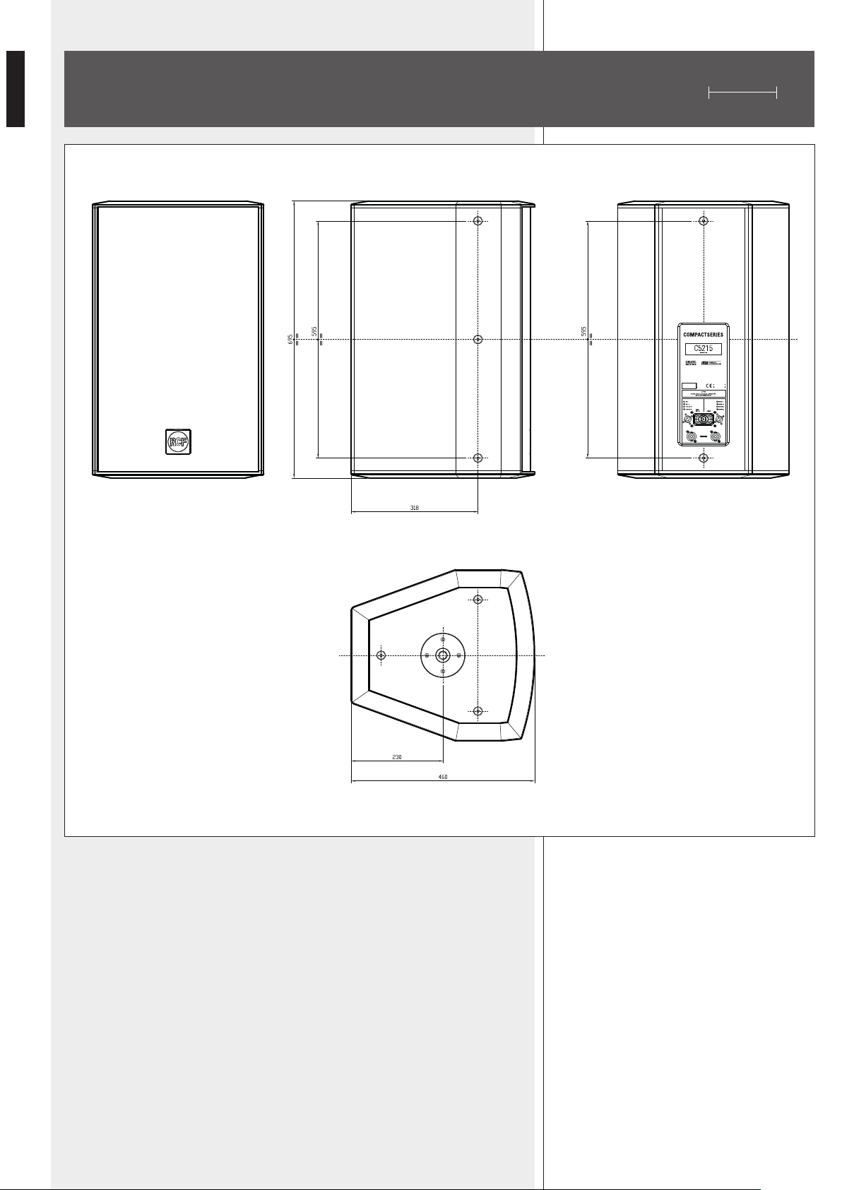
C 5215 DIMENSIONS
mm

15
ITALIANO
INDICE
AVVERTENZE PER LA SICUREZZA
DESCRIZIONE
INSTALLAZIONE
COLLEGAMENTI
NOTE SUI SISTEMI CON CONNESSIONE A BASSA IMPEDENZA
DATI TECNICI
DIMENSIONI C 5212, C 7312
DIMENSIONI C 5215, C 9315
16
18
19
22
23
24
25
26

16
ITALIANO
IMPORTANTE
Prima di collegare ed utilizzare questo prodotto, leggere attentamente le istruzioni
contenute in questo manuale, il quale è da conservare per riferimenti futuri. Il presente
manuale costituisce parte integrante del prodotto e deve accompagnare quest’ultimo
anche nei passaggi di proprietà, per permettere al nuovo proprietario di conoscere le
modalità d’installazione e d’utilizzo e le avvertenze per la sicurezza.
L’installazione e l’utilizzo errati del prodotto esimono la RCF S.p.A. da ogni responsabilità.
ATTENZIONE: Per prevenire i rischi di amme o scosse elettriche, non esporre il diffusore
alla pioggia o all’umidità ed anche alle polveri.
AVVERTENZE PER LA SICUREZZA E PRECAUZIONI D’USO
1. Tutte le avvertenze, in particolare quelle relative alla sicurezza, devono essere lette con
particolare attenzione, in quanto contengono importanti informazioni.
2. La linea diffusori (uscita dell’amplicatore) può avere una tensione sufcientemente
alta da costituire un rischio di folgorazione per le persone: non procedere mai
all’installazione o alla connessione del diffusore quando l’amplicatore è acceso.
3. Assicurarsi che tutte le connessioni siano corrette e che l’impedenza del diffusore sia
compatibile con le caratteristiche d’uscita dell’amplicatore.
4. Accertarsi che la linea diffusori non possa essere calpestata o schiacciata da oggetti, al
ne di salvaguardarne la perfetta integrità.
5. Impedire che oggetti o liquidi entrino all’interno del prodotto, perché potrebbero
causare un corto circuito.
6. Non eseguire sul prodotto interventi / modiche / riparazioni se non quelle
espressamente descritte sul manuale istruzioni.
Contattare centri di assistenza autorizzati o personale altamente qualicato quando:
- il diffusore non funziona (o funziona in modo anomalo);
- il cavo è danneggiato;
- oggetti o liquidi sono entrati nel diffusore;
- il diffusore non è più integro (a causa di urti / incendio).
7. Nel caso che dal diffusore provengano odori anomali o fumo, spegnere
immediatamente l’amplicatore relativo alla linea e poi scollegare il diffusore.
8. Non collegare a questo diffusore apparecchi ed accessori non previsti.
Quando è prevista l’installazione sospesa, utilizzare solamente gli appositi punti di
ancoraggio e non cercare di appendere il diffusore con elementi non idonei o previsti allo
scopo.
Vericare inoltre l’idoneità del supporto (parete, softto, struttura ecc.) e dei componenti
utilizzati per il ssaggio (tasselli, viti, staffe non fornite da RCF ecc.) che devono garantire
la sicurezza dell’impianto / installazione nel tempo, anche considerando, ad esempio,
vibrazioni meccaniche normalmente generate da un trasduttore.
9. La RCF S.p.A. raccomanda vivamente che l’installazione di questo prodotto sia
eseguita solamente da installatori professionali qualicati (oppure da ditte specializzate)
in grado di farla correttamente e certicarla in accordo con le normative vigenti. Tutto
il sistema audio dovrà essere in conformità con le norme e le leggi vigenti in materia di
impianti elettrici.
IMPORTANTE
AVVERTENZE PER LA SICUREZZA
E PRECAUZIONI D’USO

17
ITALIANO
10. I fattori meccanici ed elettrici sono da considerare quando si installa un sistema
audio professionale (oltre a quelli prettamente acustici, come la pressione sonora, gli
angoli di copertura, la risposta in frequenza, ecc.).
11. Perdita dell’udito
L’esposizione ad elevati livelli sonori può provocare la perdita permanente dell’udito.
Il livello di pressione acustica pericolosa per l’udito varia sensibilmente da persona
a persona e dipende dalla durata dell’esposizione. Per evitare un’esposizione
potenzialmente pericolosa ad elevati livelli di pressione acustica, è necessario che
chiunque sia sottoposto a tali livelli utilizzi delle adeguate protezioni; quando si fa
funzionare un trasduttore in grado di produrre elevati livelli sonori è necessario indossare
dei tappi per orecchie o delle cufe protettive.
Consultare i dati tecnici contenuti nel manuale istruzioni per conoscere la massima
pressione sonora che il diffusore acustico è in grado di produrre.
12. I diffusori devono essere collegati in fase (corrispondenza delle polarità +/– tra
amplicatori e diffusori) in modo da garantire una corretta riproduzione audio,
soprattutto quando i diffusori sono collocati in posizione fra loro adiacente o nello stesso
ambiente.
13. Per evitare che fenomeni induttivi diano luogo a ronzii, disturbi e compromettano
il buon funzionamento dell’impianto, le linee diffusori non devono essere canalizzate
insieme ai conduttori dell’energia elettrica, ai cavi microfonici, alle linee di segnale a
basso livello che fanno capo ad amplicatori.
14. Il cavo per il collegamento del diffusore dovrà avere conduttori di sezione adeguata
(possibilmente intrecciati, per minimizzare gli effetti induttivi dovuti all’accoppiamento
con campi elettromagnetici circostanti) ed un isolamento idoneo.
15. Non collegare l’ingresso a bassa impedenza del diffusore acustico ad una linea a
tensione costante (100 V).
16. Collocare il diffusore lontano da fonti di calore.
17. Non sovraccaricare il diffusore con una potenza eccessiva.
18. Non usare solventi, alcool, benzina o altre sostanze volatili per la pulitura delle parti
esterne; usare un panno asciutto.
18
ITALIANO
RCF S.P.A. VI RINGRAZIA PER L’ACQUISTO DI QUESTO PRODOTTO, REALIZZATO
IN MODO DA GARANTIRNE L’AFFIDABILITÀ E PRESTAZIONI ELEVATE.
DESCRIZIONE
La nuova serie “Compact” comprende una vasta gamma di diffusori acustici passivi a 2
Matching Design”, la quale garantisce una transizione ottimale tra la risposta polare
della tromba per le alte frequenze e la direttività del trasduttore (il woofer) per le basse
frequenze. La tromba (per le alte frequenze) è ruotabile, permettendo l’uso del diffusore
acustico sia in posizione verticale sia in quella orizzontale.
Questo manuale riguarda 4 modelli della nuova serie:
- C 5212 sistema a 2 vie con woofer (per le basse frequenze) da 12 pollici (con bobina
da 3 pollici) e driver (per le alte frequenze) da 1,4 pollici (con bobina da 2,5 pollici);
- C 5215 sistema a 2 vie con woofer da 15 pollici (con bobina da 3 pollici) e driver da
1,4 pollici (con bobina da 2,5 pollici);
I modelli C 5212 e C 5215 sono disponibili in 5 diverse versioni (identificabili dal suffisso
al nome) che differiscono nella dispersione della tromba del driver per le alte frequenze:
- C 5212-64, C 5212 con dispersione 60° (orizzontale) x 40° (verticale);
- C 5212-66, C 5212 con dispersione 60° (orizzontale) x 60° (verticale);
- C 5212-94, C 5212 con dispersione 90° (orizzontale) x 40° (verticale);
- C 5212-96, C 5212 con dispersione 90° (orizzontale) x 60° (verticale);
- C 5212-99, C 5212 con dispersione 90° (orizzontale) x 90° (verticale);
- C 5215-64, C 5215 con dispersione 60° (orizzontale) x 40° (verticale);
- C 5215-66, C 5215 con dispersione 60° (orizzontale) x 60° (verticale);
- C 5215-94, C 5215 con dispersione 90° (orizzontale) x 40° (verticale);
- C 5215-96, C 5215 con dispersione 90° (orizzontale) x 60° (verticale);
- C 5215-99, C 5215 con dispersione 90° (orizzontale) x 90° (verticale).
Tutti i modelli sono attentamente assemblati in Italia (nella sede principale) e montano
woofer e driver RCF che rappresentano il meglio della tecnologia più recente inerente ai
trasduttori acustici.
I diffusori sono dotati di un crossover RCF compensato a bassa impedenza (“Low Impedance
Compensated Crossover”) con protezione elettronica del driver; è inoltre possibile il
uno per le alte) utilizzando un crossover esterno.
diverse possibilità d’installazione (rapida e sicura).
Le griglie frontali in acciaio sono protette da una robusta maglia a doppia rete di poliestere.
Il logo RCF frontale è facilmente ruotabile.
Tutta la serie è equipaggiata con supporti a disco, sul lato superiore ed inferiore, per il
Sono presenti inoltre punti d’installazione sul pannello posteriore.
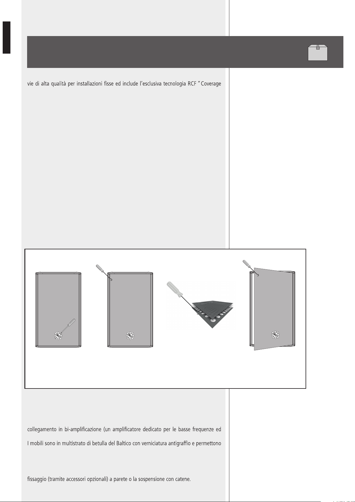
COME RIMUOVERE LA GRIGLIA PER AVERE ACCESSO ALLA TROMBA
Ruotare il logo RCF di
45° per esporre le due
viti, dopodichè svitare le
viti.
Con l’aiuto di un uncino,
passare attraverso il filtro
della rete e localizzare un
foro su un lato della griglia
di metallo
Una volta che l’uncino è
agganciato alla griglia in
metallo, tirare delicatamente. In
questo modo la griglia si
solleverà e potrà essere rimossa
La griglia di metallo è situata sotto a
uno strato di filtro.
L’UNCINO DEVE AGGANCIARSI ALLA
GRIGLIA DI METALLO.
NON TIRARE SE L’UNCINO E’
AGGANCIATO SOLO AL FILTRO.
19
ITALIANO
Ogni modello ha sul pannello posteriore 2 prese (poste in parallelo, in modo da avere un
ingresso ed un’uscita) per connettori “Neutrik Speakon NL4” (a 4 poli).
INSTALLAZIONE
L
’installazione dei diffusori deve essere effettuata da personale qualicato rispettando gli
standard di sicurezza. Eseguire un’installazione sicura di ogni diffusore, controllando che la
struttura di supporto (es. parete, softto, ecc.) abbia le necessarie caratteristiche meccaniche,
tali da consentirle di sopportarne il peso senza il pericolo di cadute che potrebbero
compromettere l’incolumità di persone e/o danneggiare cose.
Utilizzare elementi di ssaggio adatti al tipo di struttura che deve sostenere i diffusori (es.
tasselli per mattoni forati, tasselli per calcestruzzo, ecc.).
a) INSTALLAZIONE IN POSIZIONE ORIZZONTALE TRAMITE STAFFA AD U
ACCESSORIO OPZIONALE NECESSARIO:
- AC NC12 H-BR (per C 5212-64, C 5212-66, C 5212-94, C 5212-96,
C 5212-99);
- AC NC15 H-BR (per C 5215-64, C 5215-66, C 5215-94, C 5215-96,
C 5215-99).
Fissare la staffa ad U alla parete od al softto tramite almeno 4 tasselli laterali (max. M8) ed
uno centrale (max. M10).
Installare il diffusore alla staffa ad U avvitando i due bulloni M10x35 nei due fori centrali dei
supporti a disco, come mostrato nella gura sotto.
Come alternativa, è possibile un’installazione un po’ meno sporgente grazie ai fori più interni
della staffa ad U.
Prima di stringere i due bulloni M10, regolare l’inclinazione verticale del diffusore e
successivamente (quando si è certi dell’angolo) ssarla tramite due bulloni M5x20 in uno dei 7
piccoli fori della staffa ad U adiacenti a quelli per i bulloni.
Nota: NoN iNcliNare il diffusore verso l’alto!
iN alterNativa ai semplici bulloNi m10, è possibile utilizzale le maNopole (coN bulloNi m10) iN dotazioNe.
20
ITALIANO
b) INSTALLAZIONE IN POSIZIONE VERTICALE TRAMITE STAFFA AD U
ACCESSORIO OPZIONALE NECESSARIO:
-
AC NC12 V-BR
(per C 5212-64, C 5212-66, C 5212-94, C 5212-96, C 5212-99);
- AC NC15 V-BR
(per C 5215-64, C 5215-66, C 5215-94, C 5215-96, C 5215-99).
Fissare la staffa ad U alla parete od al soffitto tramite almeno 4 tasselli laterali (max.
M8) ed uno centrale (max. M10).
Installare il diffusore alla staffa ad U avvitando i due bulloni M10x35 nei due fori laterali
del diffusore acustico, come mostrato nella figura sotto.
Come alternativa, è possibile un’installazione un po’ meno sporgente grazie ai fori più
interni della staffa ad U.
Prima di stringere i due bulloni M10, regolare l’inclinazione verticale del diffusore e
successivamente (quando si è certi dell’angolo) ssarla tramite due viti autolettanti
M4,2x22 (passanti per il foro piccolo della staffa a U) direttamente nel legno del
diffusore.
Nota: non inclinare il diffusore verso l’alto!
In alternativa ai semplici bulloni M10, è possibile utilizzale le manopole (con bulloni M10)
in dotazione.
21
ITALIANO
c) INSTALLAZIONE SOSPESA CON ACCESSORIO DEDICATO
ACCESSORIO OPZIONALE NECESSARIO: AC NC-FB2
L’accessorio AC NC-FB2 è una staffa forata che permette la sospensione del diffusore
acustico con l’uso di 2 grilli M10 e catene (non inclusi).
Fissare l’accessorio AC NC-FB2 al supporto a disco superiore del diffusore acustico
tramite 4 viti M5 a testa piana svasata (come mostrato nella gura sotto).
22
ITALIANO
COLLEGAMENTI
ATTENZIONE: per il collegamento del diffusore si raccomanda di rivolgersi a personale
qualicato ed addestrato, ossia personale avente conoscenze tecniche o esperienza o
istruzioni speciche sufcienti per permettergli di realizzare correttamente le connessioni e
prevenire i pericoli dell’elettricità.
Per evitare il rischio di shock elettrici, non collegare il diffusore con l’amplicatore acceso.
Prima di far funzionare il diffusore, è buona norma ricontrollare tutte le
connessioni, vericando attentamente che non vi siano dei cortocircuiti
accidentali. Tutto l’impianto di sonorizzazione dovrà essere realizzato in
conformità con le norme e le leggi vigenti in materia di impianti elettrici.
L’uso dei diffusori acustici della serie “Compact” è previsto per i soli ambienti
chiusi; se installati all’aperto, i diffusori dovranno essere protetti dall’acqua.
Sul pannello posteriore sono presenti:
- un commutatore tra i modi “FULL RANGE” (amplicazione unica ed uso del
crossover interno) e “BI-AMP” (bi-amplicazione e crossover esterno);
- 2 prese (poste in parallelo) per connettori “Neutrik Speakon NL4” (a 4 poli)
che fungono sia da ingresso sia da uscita.
MODO “FULL-RANGE”
L’impedenza di ciascun diffusore è 8 Ω.
Collegare il conduttore positivo (uscita “+” dell’amplicatore) al contatto 1+ del
connettore SPEAKON; collegare il conduttore negativo (uscita “–” dell’amplicatore) al
contatto 1– del connettore SPEAKON. I contatti 2+ e 2– non sono utilizzati.
MODO “BI-AMP” (bi-amplicazione)
Occorrono due amplicatori (uno per le basse frequenze ed uno per le alte) ed un
crossover esterno. Vericare nella tabella dei dati tecnici l’impedenza di ciascuna sezione,
le potenze applicabili e la frequenza suggerita di crossover.
Collegamenti:
- uscita + dell’amplicatore basse frequenze al contatto 1+ del connettore SPEAKON;
- uscita – dell’amplicatore basse frequenze al contatto 1– del connettore SPEAKON;
- uscita + dell’amplicatore alte frequenze al contatto 2+ del connettore SPEAKON;
- uscita – dell’amplicatore alte frequenze al contatto 2– del connettore SPEAKON.
LOW
HIGH
CROSSOVER
AMP.
AMP.
23
ITALIANO
NOTE SUI SISTEMI CON CONNESSIONE A BASSA IMPEDENZA
- L’impedenza totale dei diffusori non deve essere inferiore a quella d’uscita
dell’amplicatore; nota: l’impedenza complessiva dei diffusori uguale a quella d’uscita
dell’amplicatore permette l’erogazione della massima potenza (mentre un’impedenza
superiore comporta una riduzione della potenza erogata).
- La somma delle potenze dei diffusori deve essere adeguata alla potenza massima
erogabile dall’amplicatore.
- La lunghezza delle linee diffusori deve essere ridotta al minimo (una lunga distanza
può comportare l’uso di cavi con sezioni elevate).
- Utilizzare dei cavi con conduttori aventi una sezione adeguata, considerando la loro
lunghezza e la potenza complessiva dei diffusori.
- Per evitare che fenomeni induttivi diano luogo a ronzii, disturbi e compromettano il
funzionamento del sistema, i cavi per i diffusori non devono essere canalizzati assieme
ai conduttori dell’energia elettrica, ai cavi microfonici od altre linee.
- Per minimizzare gli effetti induttivi (ronzii) dovuti all’accoppiamento con campi elettro-
magnetici circostanti, utilizzare cavi con conduttori intrecciati.
- NON collegare gli ingressi dei diffusori direttamente ad una linea a tensione costante
(es. 100 V).
- +
IMPEDENZA COMPLESSIVA: 4 Ω
8 Ω
8 Ω
+
+
- +
IMPEDENZA COMPLESSIVA: 8 Ω
8 Ω
+
24
ITALIANO
MODEL C 5212-64 C 5212-66 C 5212-94 C 5212-96 C 5212-99
IMPEDENZA (‘full range’) 8 Ω 8 Ω 8 Ω 8 Ω 8 Ω
POTENZA RMS, (“full-range”) 500 W 500 W 500 W 500 W 500 W
IMPEDENZE (‘bi-amp’)
8 Ω (LF)
8 Ω (HF)
8 Ω (LF)
8 Ω (HF)
8 Ω (LF)
8 Ω (HF)
8 Ω (LF)
8 Ω (HF)
8 Ω (LF)
8 Ω (HF)
POTENZE (AES, “bi-amp”)
400 W (LF)
100 W (HF)
400 W (LF)
100 W (HF)
400 W (LF)
100 W (HF)
400 W (LF)
100 W (HF)
400 W (LF)
100 W (HF)
FREQUENZA DI CROSSOVER 1,2 kHz 1,2 kHz 1,2 kHz 1,2 kHz 1,2 kHz
RISPOSTA IN FREQUENZA (-10dB) 60 Hz ÷ 20 kHz 60 Hz ÷ 20 kHz 60 Hz ÷ 20 kHz 60 Hz ÷ 20 kHz 60 Hz ÷ 20 kHz
SENSIBILITÀ (1 W / 1 m) 98 dB 98 dB 98 dB 98 dB 98 dB
PRESSIONE SONORA (1 m) 125 dB (500 W) 125 dB (500 W) 125 dB (500 W) 125 dB (500 W) 125 dB (500 W)
WOOFER 12” (bob. 3”) 12” (bob. 3”) 12” (bob. 3”) 12” (bob. 3”) 12” (bob. 3”)
DRIVER 1,4” (bob. 2,5”) 1,4” (bob. 2,5”) 1,4” (bob. 2,5”) 1,4” (bob. 2,5”) 1,4” (bob. 2,5”)
DISPERSIONE (oriz. x vert.) 60° x 40° 60° x 60° 90° x 40° 90° x 60° 90° x 90°
PESO NETTO 29 kg 29 kg 29 kg 29 kg 29 kg
MODEL C 5215-64 C 5215-66 C 5215-94 C 5215-96 C 5215-99
IMPEDENZA (‘full range’) 8 Ω 8 Ω 8 Ω 8 Ω 8 Ω
POTENZA (RMS, “full range”) 500 W 500 W 500 W 500 W 500 W
IMPEDENZE (‘bi-amp’) 8 Ω(LF)-8 Ω(HF) 8 Ω(LF)-8 Ω(HF) 8 Ω(LF)-8 Ω(HF) 8 Ω(LF)-8 Ω(HF) 8 Ω(LF)-8 Ω(HF)
POTENZE (AES, “bi-amp”)
400 W (LF)
100 W (HF)
400 W (LF)
100 W (HF)
400 W (LF)
100 W (HF)
400 W (LF)
100 W (HF)
400 W (LF)
100 W (HF)
FREQUENZA DI CROSSOVER 1,2 kHz 1,2 kHz 1,2 kHz 1,2 kHz 1,2 kHz
RISPOSTA IN FREQUENZA (-10 dB) 55 Hz ÷ 20 kHz 55 Hz ÷ 20 kHz 55 Hz ÷ 20 kHz 55 Hz ÷ 20 kHz 55 Hz ÷ 20 kHz
SENSIBILITÀ (1 W / 1 m) 99 dB 99 dB 99 dB 99 dB 99 dB
PRESSIONE SONORA (1 m) 126 dB (500W) 126 dB (500W) 126 dB (500W) 126 dB (500W) 126 dB (500W)
WOOFER 15” (bob. 3”) 15” (bob. 3”) 15” (bob. 3”) 15” (bob. 3”) 15” (bob. 3”)
DRIVER 1,4” (bob. 2,5”) 1,4” (bob. 2,5”) 1,4” (bob. 2,5”) 1,4” (bob. 2,5”) 1,4” (bob. 2,5”)
DISPERSIONE (ORIZ. X VERT.) 60° x 40° 60° x 60° 90° x 40° 90° x 60° 90° x 90°
PESO NETTO 34,8 kg 34,8 kg 34,8 kg 34,8 kg 34,8 kg
DATI TECNICI
CORPO: multistrato di betulla COLORE: nero

25
ITALIANO
DIMENSIONI C 5212
mm

26
ITALIANO
DIMENSIONI C 5215
mm


10307322 RevD
www.rcfaudio.com
HEADQUARTERS:
RCF S.p.A. Italy
tel. +39 0522 274 411
e-mail: info@rcf.it
RCF UK
tel. 0844 745 1234
Int. +44 870 626 3142
e-mail: [email protected].uk
RCF France
tel. +33 1 49 01 02 31
e-mail: france@rcf.it
RCF Germany
tel. +49 2203 925370
e-mail: germany@rcf.it
RCF Spain
tel. +34 91 817 42 66
e-mail: [email protected]
RCF Belgium
tel. +32 (0) 3 - 3268104
e-mail: belgium@rcf.it
RCF USA Inc.
tel. +1 (603) 926-4604
e-mail: [email protected]
Except possible errors and omissions.
RCF S.p.A. reserves the right to make modications without prior notice.
Salvo eventuali errori ed omissioni.
RCF S.p.A. si riserva il diritto di apportare modiche senza preavviso.