1
!
WARNING
TO REDUCE THE RISK OF FIRE, ELECTRIC SHOCK, OR INJURY
TO PERSONS, OBSERVE THE FOLLOWING:
1. Use this unit only in the manner intended by the manufacturer.
If you have questions, contact the manufacturer at the address
or telephone number listed in the warranty.
2. Before servicing or cleaning unit, switch power off at service
panel and lock the service disconnecting means to prevent
power from being switched on accidentally. When the service
disconnecting means cannot be locked, securely fasten a promi-
nent warning device, such as a tag, to the service panel.
3. Installationworkandelectricalwiringmustbedonebyaqualied
person(s) in accordance with all applicable codes and stan-
dards,includingre-ratedconstructioncodesandstandards.
4. Sufcientairisneededforpropercombustionandexhausting
of gases through the ue (chimney) of fuel burning equip-
ment to prevent backdrafting. Follow the heating equipment
manufacturer’s guideline and safety standards such as those
published by the National Fire Protection Association (NFPA),
and the American Society of Heating, Refrigeration and Air
Conditioning Engineers (ASHRAE), and the local code authori-
ties.
5. When cutting or drilling into wall or ceiling, do not damage
electrical wiring and other hidden utilities.
6. Toreducetheriskofreorelectricshock,donotusethisrange
hood with an additional speed control device.
7. Ducted fans must always be vented to the outdoors.
8. Toreducetheriskofre,useonlymetalductwork.
9. Use with approved cord-connection kit only.
10. This unit must be grounded.
TO REDUCE THE RISK OF A RANGE TOP GREASE FIRE:
1. Never leave surface units unattended at high settings. Boilovers
cause smoking and greasy spillovers that may ignite. Heat oils
slowly on low or medium settings.
2. Always turn hood ON when cooking at high heat or when cooking
amingfoods.
3. Clean ventilating fans frequently. Grease should not be allowed
toaccumulateonfanorlter.
4. Use proper pan size. Always use cookware appropriate for the
size of the surface element.
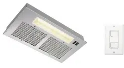
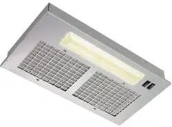
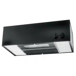
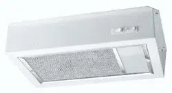
POWER MODULE
READ AND SAVE THESE INSTRUCTIONS
MODEL
PM44
WARNING
TO REDUCE THE RISK OF INJURY TO PERSONS IN THE EVENT
OF A RANGE TOP GREASE FIRE, OBSERVE THE FOLLOW-
ING:*
1.SMOTHERFLAMESwithaclose-ttinglid,cookie sheet, or
metal tray, then turn off the burner. BE CAREFUL TO PREVENT
BURNS.Iftheamesdonotgooutimmediately,EVACUATE
AND CALL THE FIRE DEPARTMENT.
2. NEVER PICK UP A FLAMING PAN — You may be burned.
3. DO NOT USE WATER, including wet dishcloths or towels -
violentsteamexplosionwillresult.
4.UseanextinguisherONLYif:
A. You know you have a Class ABC extinguisher and you
already know how to operate it.
B. Thereissmallandcontainedintheareawhereitstart-
ed.
C. Theredepartmentisbeingcalled.
D. Youcanghttherewithyourbacktoanexit.
* Based on “Kitchen Fire Safety Tips” published by NFPA.
CAUTION
1. Forgeneralventilatinguseonly.Donotusetoexhausthazard-
ousorexplosivematerialsandvapors.
2. To avoid motor bearing damage and noisy and/or unbalanced
impellers, keep drywall spray, construction dust, etc. off power
unit.
3. For best capture of cooking impurities, your range hood should
be mounted so that the top of the hood is 24-30” above the
cooking surface.
4. Pleasereadspecicationlabelonproductforfurtherinformation
and requirements.
Installer: Leave this manual with the homeowner.
Homeowner: Operating and Cleaning information on page 3.
!
INTENDED FOR DOMESTIC COOKING ONLY
!
2
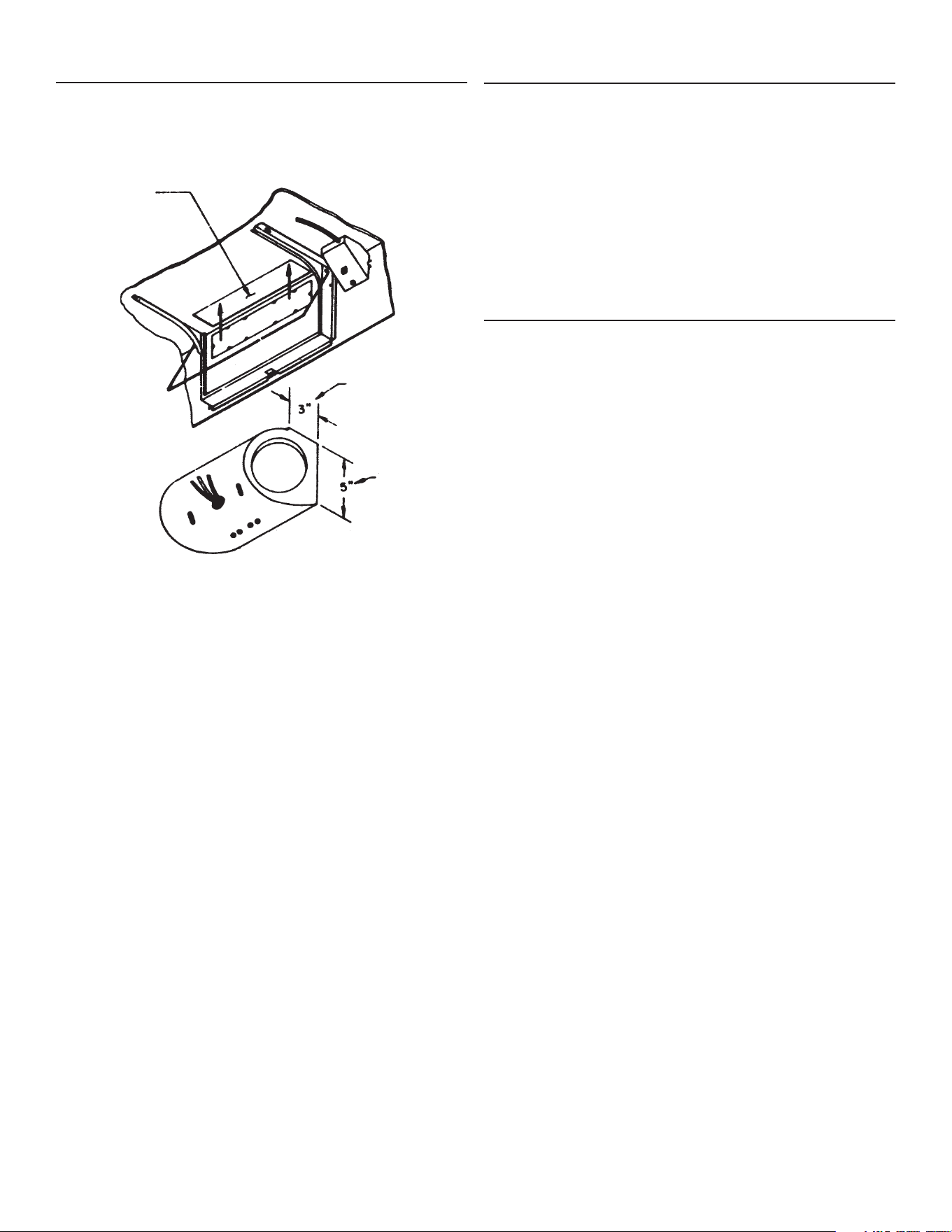
VENTILATING AND WIRING
CUTOUTS
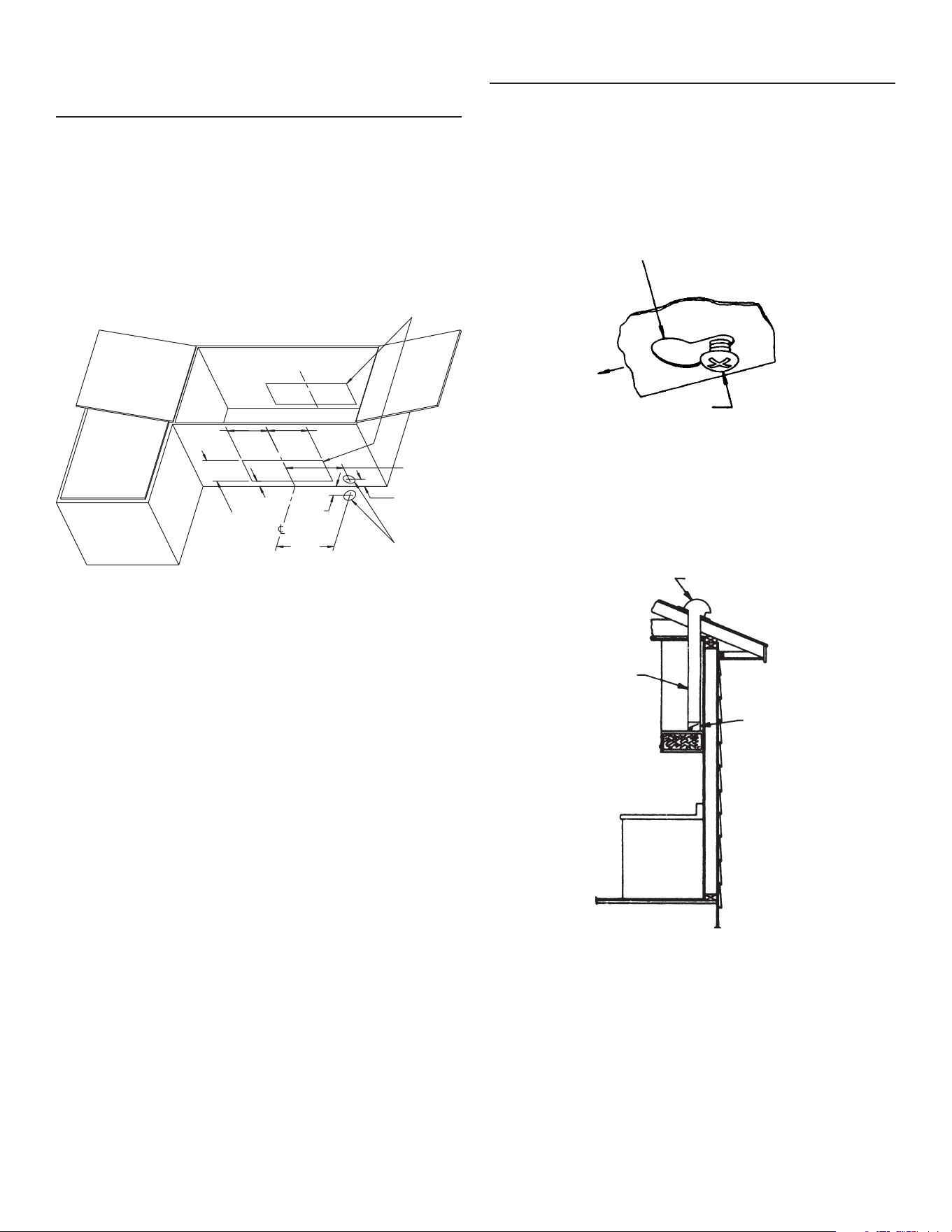
1. Mark locations on cabinet for ventilating duct and electrical
wiring from the dimensions given (FIGURE 1).
2. Cut holes at the marked locations to accommodate the ventilat-
ing duct and electrical wiring. Be sure to minimize openings,
these will have to be sealed later.
3. Run house wiring through 1-1/2” diameter hole in cabinet or wall.
Be sure all wiring is in accordance with the National Electrical
Code and local ordinances.
INSTALLATION
1. Removetheblower/lenscoverandltersforeasierinstallation.
Seetheexplodedassemblyillustration(FIGURE5).Remove
the shipping material from the inside of the ventilator.
2. Lift the ventilator into position. Mark the screw hole locations,
on the cabinet, at the center of the narrow end of each of the
(4) keyhole slots.
3. Remove the unit. Start each mounting screw into the cabinet
at the positions marked in Step 2. (FIGURE 2)
DAMPER ASSEMBLY
ROOF / WALL CAP
3-1/4” x 10”
DUCT
KEYHOLE SLOT
IN VENTILATOR
MOUNTING SCREW
#10 x 5/8 Phillips - 4 provided)
FIGURE 1
FIGURE 2
FIGURE 3
1-3/8"
3,5 cm
7-1/2"
19,1 cm
1"
2,5 cm
4"
10,2 cm
5-1/4"
13,3 cm
7-1/2"
3,5 cm
1-3/8"
2,5 cm
ELECTRICAL WIRING
LOCATION OPTIONS
1-1/2" DIAMETER
5-1/4"
13,3 cm
CABINET
CUTOUTS
4. Attachthe3¼”x10”damperassemblytothedischargeopening
intheventilatorhousing.Usethesheetmetalscrews(#8x¼)
provided.
5. Remove the junction box cover and appropriate electrical
knockout from the ventilator for access to the wiring.
6. Install the proper ductwork (FIGURE 3). Use duct tape to make
connections secure and air tight.
7. Lift the ventilator into position and feed the house wiring through
the ventilator’s electrical knockout.
8. Tighten the (4) mounting screws to secure the ventilator to the
cabinet. Be sure the screw heads remain in the narrow end of
the keyhole slots (FIGURE 2).
9. Completetheelectricalwiringinthejunctionbox,accordingto
the National Electrical Code and local ordinances.
10.Replacethejunctionboxcover.
11.Installa75-Watt(maximum)lightbulb.
12.Replacetheblower/lenscoverandlters.
3
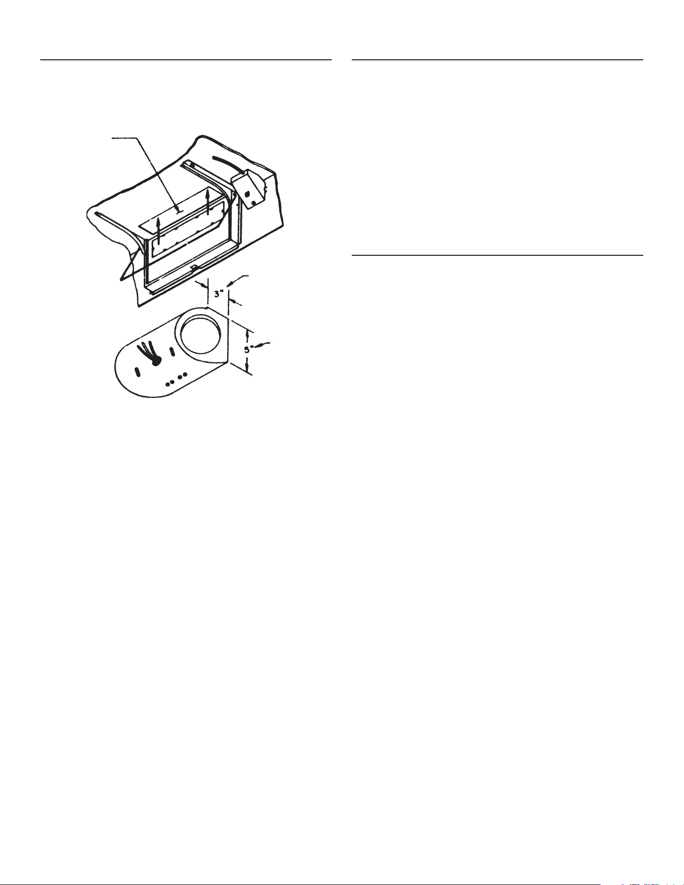
BLOWER ORIENTATION
IMPORTANT: Be sure the blower is correctly orientated. Note ar-
rowonthesideoftheblowerhousingindicatingthecorrectairow
direction (FIGURE 4).
VERTICAL
DISCHARGE
VENT
(TOP OF HOOD)
BLOWER
DISCHARGE
– LOCATE AT
DISCHARGE
VENT IN TOP
OF HOOD
THIS
SURFACE
TO REAR
FIGURE 4 – VERTICAL DISCHARGE
TO CHANGE LIGHT BULB
Remove lens cover by squeezing the retention tab and rotating the
lensout.Removeoldbulbandreplacewitha75-Watt(maximum)
bulb. Replace lens cover.
CLEANING INFORMATION
FILTER
Forgreatestefciency,thealuminumltersshouldberemovedand
cleanedperiodically.Toremovethelters,loosenthescrewinthe
centerofeachlter.
Toclean,theltershouldbesoakedinhotwateranddetergent
thenthoroughlyrinsed.Thealuminumltercanbecleanedina
dishwasher.
EXTERIOR SURFACE
To preserve its lasting beauty, clean with a mild detergent. DO NOT
use abrasive cleaners.
MOTOR SPEED
TROUBLESHOOTING
If you have a motor speed problem, please check the following list
for possible troubles.
1. Blower assembly installed wrong - instended for vertical dis-
charge, but installed for horizontal discharge (FIGURE 4).
2. Damperap-notopening.
3. Reducedairowbecausetheductistoosmall,toolong,orhas
too many transitions in the system.
4. Restriction in the duct (foreign matter, debris).
5. Undersized or restructive roff or wall cap.
6. Damperapinrooforwallcap-notopening.
7. Wait for 20-30 seconds between speed changes for RPM to
adjust.
By removing or correcting these adverse factors, the motor speed
controlwillbeabletodecreasefrommaximumRPM.
4
WARRANTY
BROAN-NUTONE ONE YEAR LIMITED WARRANTY
Broan-NuTone warrants to the original consumer purchaser of its products that such
products will be free from defects in materials or workmanship for a period of one
year from the date of original purchase. THERE ARE NO OTHER WARRANTIES,
EXPRESS OR IMPLIED, INCLUDING, BUT NOT LIMITED TO, IMPLIED WARRAN-
TIES OF MERCHANTABILITY OR FITNESS FOR A PARTICULAR PURPOSE.
During this one-year period, Broan-NuTone will, at its option, repair or replace,
without charge, any product or part which is found to be defective under normal
use and service.
THIS WARRANTY DOES NOT EXTEND TO FLUORESCENT LAMP STARTERS
AND TUBES. This warranty does not cover (a) normal maintenance and service or
(b) any products or parts which have been subject to misuse, negligence, accident,
improper maintenance or repair (other than by Broan-NuTone), faulty installation or
installation contrary to recommended installation instructions.
The duration of any implied warranty is limited to the one-year period as specified
for the express warranty. Some states do not allow limitation on how long an implied
warranty lasts, so the above limitation may not apply to you.
BROAN-NUTONE’S OBLIGATION TO REPAIR OR REPLACE, AT BROAN-
NUTONE’S OPTION, SHALL BE THE PURCHASER’S SOLE AND EXCLUSIVE
REMEDY UNDER THIS WARRANTY. BROAN-NUTONE SHALL NOT BE LIABLE
FOR INCIDENTAL, CONSEQUENTIAL OR SPECIAL DAMAGES ARISING OUT OF
OR IN CONNECTION WITH PRODUCT USE OR PERFORMANCE. Some states
do not allow the exclusion or limitation of incidental or consequential damages, so
the above limitation or exclusion may not apply to you.
This warranty gives you specific legal rights, and you may also have other rights,
which vary from state to state. This warranty supersedes all prior warranties.
To qualify for warranty service, you must (a) notify Broan-NuTone at the address
or phone number below, (b) give the model number and part identification and (c)
describe the nature of any defect in the product or part. At the time of requesting
warranty service, you must present evidence of the original purchase date.
Broan-NuTone LLC Hartford, Wisconsin www.broan.com 800-558-1711
Broan-NuTone Canada Mississauga, Ontario www.broan.ca 877-896-1119
626922D
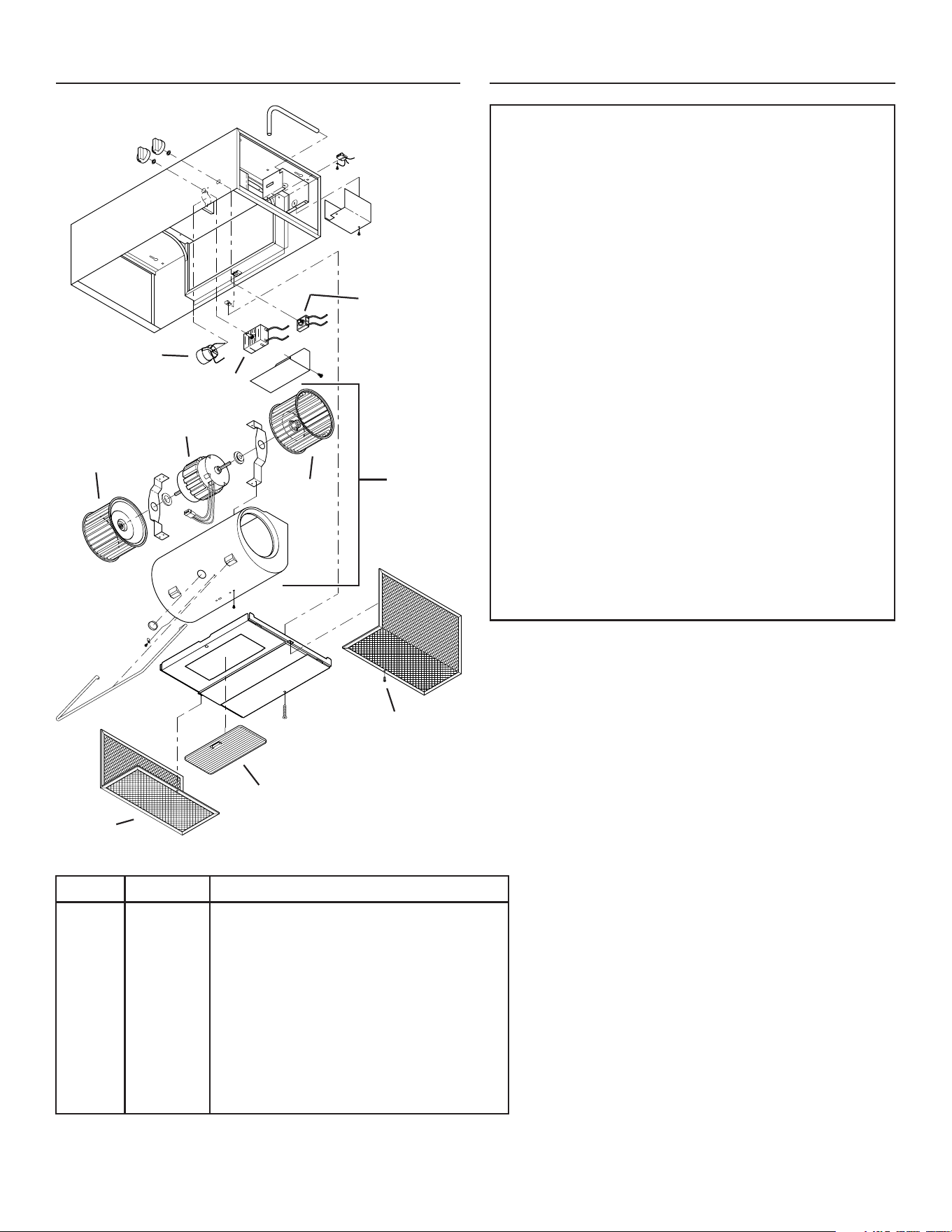
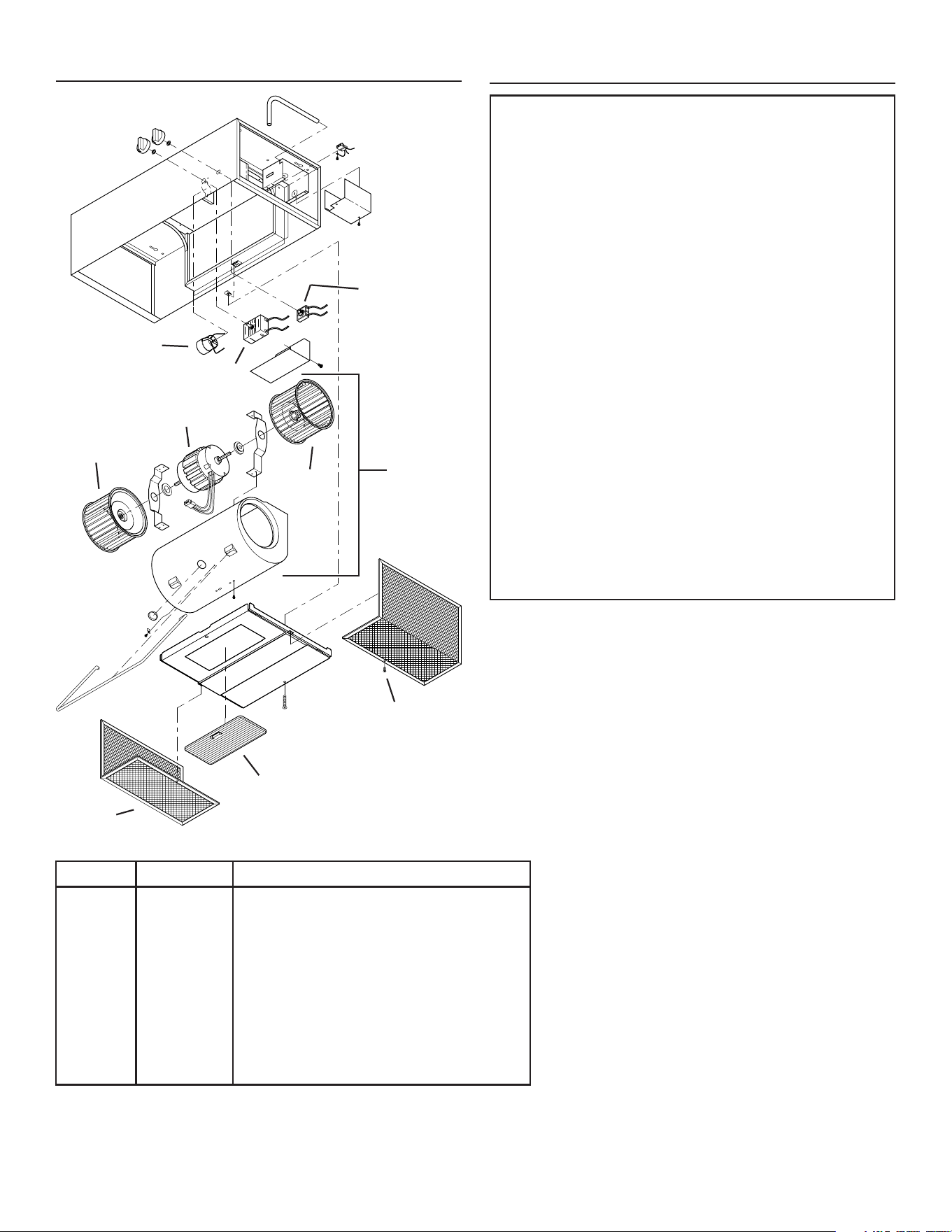
Key No. Part No. Description
1 R566066 Lampholder
2 R567073 Motor, Speed Control
3 R561107 3-Pos. Rotary Light Switch
4 R520098 Motor
5 R531041 Blower Wheel CW
6 R531042 Blower Wheel CCW
7 R730079 Blower Assembly (includes Key Nos. 4, 5, 6)
8 R610080 Filter
R610081 Filter (combination) used with 355NDK Kit
9 97013316 Light Lens
10 R602539 Screw
* 355NDK Non-Duct Recirculation Kit
SERVICE PARTS
* Optional accessory - purchase separately.
3
2
1
4
5
6
7
8
9
10
5
!
AVERTISSEMENT
AFIN DE RÉDUIRE LES RISQUES D’INCENDIE, DE CHOC ÉLEC-
TRIQUE OU DE BLESSURES CORPORELLES, VEUILLEZ OB-
SERVEZ LES DIRECTIVES SUIVANTES :
1. N’utilisez cet appareil que de la manière prévue par le fabricant.
Si vous avez des questions, communiquez avec le fabricant à
l’adresse ou au numéro de téléphone indiqués dans la garantie.
2. Avant de procéder à la réparation ou à l’entretien de l’appareil,
coupez l’alimentation du panneau d’entrée d’électricité et verrouillez
l’interrupteurprincipaland’empêcherquelecourantnesoitac-
cidentellement rétabli. S’il est impossible de verrouiller l’interrupteur
principal,xezsolidementunmessaged’avertissement,parex-
emple une étiquette, au panneau d’entrée d’électricité.
3. Laposedel’appareiletlestravauxd’électricitédoiventêtreeffec-
tuéspardespersonnesqualiéesconformémentàlaréglementa-
tion en vigueur, notamment les normes de la construction ayant
trait à la protection contre les incendies.
4. Pouréviterlesrefoulements,l’apportd’airdoitêtresufsantpour
brûler les gaz produits par les appareils à combustion et les évacuer
dans le conduit de fumée (cheminée). Respectez les directives
du fabricant de l’appareil de chauffage et les normes de sécurité,
notamment celles publiées par la National Fire Protection Asso-
ciation (NFPA), l’American Society of Heating, Refrigeration and
Air Conditioning Engineers (ASHRAE) et les codes des autorités
locales.
5. Veillez à ne pas endommager le câblage électrique ou d’autres
équipements non apparents lors de la découpe ou du perçage du
mur ou du plafond.
6. Pour réduire les risques d’incendie et de choc électrique, n’utilisez
pas de commande de régime supplémentaire pour cette hotte de
cuisine.
7. Les ventilateurs canalisés doivent toujours être ventilés à l’air
libre.
8. Pour réduire les risques d’incendie, utilisez seulement des conduits
en métal.
9. Utilisation avec le kit approuvé de corde-raccordement seule-
ment.
10. Cetappareildoitêtremisàlaterre.
POUR RÉDUIRE LES RISQUES D’INCENDIE CAUSÉS PAR DE LA
GRAISSE SUR LE PLAN DE CUISSON :
1. Ne laissez jamais les éléments de surface allumés à haute tempéra-
ture. Les débordements peuvent causer de la fumée et occasionner
desécoulementsdegraisseinammables.L’huiledoitêtrechauffée
graduellement à basse ou à moyenne température.
2. Mettez toujours la hotte en fonction (ON) lors de la cuisson à haute
températureoulorsdelacuissond’alimentssusceptiblesdeam-
ber.
3. Nettoyez souvent la hotte. Ne laissez pas la graisse s’accumuler
surleventilateurouleltre.
4. Utilisez des casseroles de dimension appropriée. Utilisez toujours
une batterie de cuisine adaptée à la dimension des éléments de
surface.
MODULE MOTORISÉ
VEUILLEZ LIRE CES DIRECTIVES ET LES CONSERVER
MODÈLE
PM44
Installateur : Veuillez laisser ce
manuel au propriétaire.
Propriétaire : Voir les instructions
d’utiLisation et de nettoyage en
page 3.
AVERTISSEMENT
OBSERVEZ LES CONSIGNES SUIVANTES* DE MANIÈRE À
RÉDUIRE LES RISQUES DE BLESSURES CORPORELLES EN
CAS D’INCENDIE CAUSÉ PAR DE LA GRAISSE SUR LE PLAN DE
CUISSON.
1. ÉTOUFFEZ LES FLAMMES à l’aide d’un couvercle étanche, d’une
tôle à biscuits ou d’un plateau en métal puis éteignez le brûleur.
FAITESATTENTIONDENEPASVOUSBRÛLER.Silesammes
ne s’éteignent pas immédiatement, QUITTEZ LES LIEUX ET AP-
PELEZ LE SERVICE DES INCENDIES.
2. NE SOULEVEZ JAMAIS UNE CASSEROLE EN FLAMMES – vous
pourriez vous brûler.
3. N’UTILISEZ PAS D’EAU, ni de serviettes ou de linges mouillés
–uneviolenteexplosiondevapeurpourraitsurvenir.
4. UtilisezunextincteurSEULEMENTsi:
A. Vous savez qu’il est de classe ABC et vous connaissez déjà son
mode de fonctionnement.
B. L’incendie n’est pas très important et ne se propage pas.
C. Vous avez déjà téléphoné au service des incendies.
D. Vous pouvez combattre l’incendie en faisant dos à une sortie.
* Conseils tirés de la publication de la NFPA “Kitchen Fire Safety
Tips”.
ATTENTION
1. Cet appareil ne doit servir qu’à la ventilation générale. Il ne doit pas
êtreutilisépouréliminerdesmatièresoudesvapeursdangereuses
ouexplosives.
2. Pour éviter d’endommager les roulements de moteur, de déséquili-
brer les pales ou de les rendre bruyantes, débarrassez l’appareil
de la poussière de plâtre, de construction, etc.
3. Pour un captage optimal des impuretés, posez la hotte entre 61 cm
et 76 cm (24 po et 30 po) au-dessus de la surface de cuisson.
4. Veuillezlirel’étiquettedespécicationsduproduitpourobtenirplus
de renseignements, notamment sur les normes.
!
DESTINÉ À LA CUISINE DOMESTIQUE SEULEMENT
!

6
DÉCOUPAGE POUR LES
CONDUITS ET LES FILS
1. Tracezsurl’armoirel’emplacementdesconduitsetdeslsselon
les dimensions indiquées (FIGURE 1).
2. Découpez les ouvertures requises pour les conduits et le câblage
électrique. Minimisez les ouvertures car elles devront être
étanchéisées par la suite.
3. Enlezlecâbledelamaisondansuntroude3,8cm(1-1/2po)
dans l’armoire ou le mur. Assurez-vous que tous les câbles sont
conformes au Code national de l’électricité et aux règlements
locaux.
INSTALLATION
1. Pour faciliter l’installation, retirez le couvercle du ventilateur/lentille
etlesltres. Voir la vue éclatée de l’assemblage (FIGURE5).
Enlevezlematérield’expéditionàl’intérieurduventilateur.
2. Soulevez le ventilateur en position. Marquez l’emplacement des vis
sous l’armoire au centre de la partie étroite des quatre (4) fentes
en trou de serrure.
3. Retirez l’unité. Enfoncez partiellement chacune des vis dans
l’armoireauxendroitsmarquésàl’étape2(FIGURE2).
ENSEMBLE DE CLAPET
CHAPEAU MURAL OU
DE TOIT
CONDUIT DE
8,3 x 25,4 cm
(3¼ x 10 po)
FENTE EN TROU DE
SERRURE
VIS DE MONTAGE
cruciformes n° 10 x 5/8 (4 incluses)
FIGURE 1
FIGURE 2
FIGURE 3
4. Fixezl’ensembledeclapetde8,3x25,4cm(3¼x10po)auconduit
de sortie dans le boîtier du ventilateur. Utilisez les vis à tôle incluses
(n°8x¼).
5. Enlevez le couvercle de la boîte de jonction ainsi que les rondelles
défonçablesappropriéespouraccéderauxls.
6. Installez les conduits correspondants (FIGURE 3). Utilisez du
rubanpourcanalisationspourxersolidementtouslesjointset
les étancher.
7. Soulevezleventilateurenpositionetenlezlecâbleélectriquede
la maison dans l’ouverture du ventilateur.
8. Serrezlesquatre(4)vispourxerleventilateursousl’armoire.
Assurez-vousquelestêtesdevisreposentbiensurlapartieétroite
des fentes en trou de serrure (FIGURE 2).
9. Effectuez les connexions électriques dans laboîte de jonction
conformémentauCodenationaldel’électricitéetauxrèglements
locaux.
10. Refermez le couvercle de la boîte de jonction.
11. Installezuneampoulede75watts(maximum).
12. Replacezlecouvercleduventilateur/lentilleetlesltres.
1-3/8"
3,5 cm
7-1/2"
19,1 cm
1"
2,5 cm
4"
10,2 cm
5-1/4"
13,3 cm
7-1/2"
3,5 cm
1-3/8"
2,5 cm
ELECTRICAL WIRING
LOCATION OPTIONS
1-1/2" DIAMETER
5-1/4"
13,3 cm
CABINET
CUTOUTS
OPTIONS
ÉLECTRIQUES
D’ENDROIT
DE CâBLAGE
DIAMÈTRE
1-1/2”
3,8 cm
DÉCOUPES DE
L’ARMOIRE
7
SORTIE
VERTICALE
(HAUT DE LA
HOTTE))
SORTIE DU
VENTILATEUR
– PLACÉE
CONTRE
LA SORTIE
SUPÉRIEURE
DE LA HOTTE
CETTE
SURFACE
VERS
L’ARRIÈRE
FIGURE 4 – SORTIE VERTICALE
POUR CHANGER L’AMPOULE
Retirez la lentille d’éclairage en enfonçant l’onglet de retenu et en
tournant la lentille. Enlevez la vieille ampoule et remplacez-la par une
ampoulede75watts(maximum).Replacezlalentilled’éclairage.
ORIENTATION DU VENTILATEUR
IMPORTANT : Assurez-vous que le ventilateur est correctement
orienté.Veuilleznoterlaèchesurlecôtéduboîtierduventilateur
indiquant le sens d’écoulement de l’air (FIGURE 4).
NETTOYAGE
FILTRE
Pouruneefcacitéoptimale,lesltresd’aluminiumdoiventêtreretirés
et nettoyés périodiquement. Pour les enlever, desserrez la vis au centre
dechaqueltre.
Faitestremperlesltresdansdel’eauchaudeadditionnéededétergent,
puisrincez-lesàfond.Lesltresd’aluminiumpeuventêtrelavésau
lave-vaisselle.
SURFACES EXTÉRIEURES
Pour préserver l’apparence du ni, nettoyez les surfaces avec un
détergentdoux.N’utilisezPASdenettoyantsabrasifs.
DÉPANNAGE POUR LE RÉGIME DU
MOTEUR
Silerégimedumoteurposeunproblème,veuillezvérierlespoints
suivants:
1. Le ventilateur est mal installé – au lieu d’une installation pour sortie
verticale, l’installation a été faite pour une sortie horizontale (FIGURE
4).
2. Le clapet ne s’ouvre pas.
3. Le débit d’air est réduit par des conduits trop étroits, trop longs ou
comportant de trop nombreuses transitions.
4. Le conduit est obstrué (objet étranger, débris).
5. Le chapeau mural ou de toit est trop petit ou fait obstruction.
6. Le clapet du chapeau mural ou de toit ne s’ouvre pas.
7. Attendez 20 à 30 secondes entre les changements de régime pour
laisser la vitesse se régler.
En corrigeant ces divers facteurs, la commande du moteur pourra en
réduire le régime.
8
626922D
GARANTIE
No de réf. No de piéce Désignation
1 R566066 Douille de lampe
2 R567073 Commande de régime du moteur
3 R561107 Interrupteur d’éclairage à 3 positions
4 R520098 Moteur
5 R531041 Roue à ailettes sens horaire
6 R531042 Roue à ailettes sens antihoraire
7 R730079 Ensemble du ventilateur
8 R610080 Filtre
R610081 Filtre (combinaison) utilisé avec le kit 355NDK
9 97013316 Lentille d’éclairage
10 R602539 Vis
* 355NDK Kit de recyclage d’air sans conduit
PIÈCES DE RECHANGE
* Accessoire facultatif - achat séparément.
GARANTIE LIMITÉE D’UN AN DE BROAN-NUTONE
Broan-NuTone garantit à l’acheteur consommateur original, de ses produits qu’ils
sont exempts de défauts dans les matières premières ou la main-d’oeuvre pour
une période d’un an à compter de la date d’achat original. IL N’Y A PAS D’AUTRES
GARANTIES, EXPRIMÉES OU IMPLICITES, INCLUANT MAIS NON PAS LIMITÉ
AUX GARANTIES IMPLICITES POUR FIN DE COMMERCIALISATION ET DE
CONVENANCE DANS UN BUT PARTICULIER.
Pendant cette période d’un an, Broan-NuTone, à son choix, réparera ou rempla-
cera, gratuitement, tout produit ou pièce qui s’avère défectueux sous utilisation et
service normaux.
CETTE GARANTIE NE COUVRE PAS LES DÉMARREURS DE LAMPES FLUO-
RESCENTES ET LES TUBES. Cette garantie ne couvre pas (a) l’entretien et le
service normal ou (b) tout produit ou pièce endommagé par suite de mauvais
usage, négligence, accident, entretien inapproprié ou réparation (autre que par
Broan-NuTone), mauvais installation ou installation contraire au mode d’installation
recommandé.
La durée de toute garantie implicite est limitée à une période d’un an tel que spécifié
pour la garantie exprimée.
L’ENGAGEMENT DE BROAN-NUTONE DE RÉPARER OU DE REMPLACER, AU
CHOIX DE BROAN-NUTONE, SERA LA SEULE OBLIGATION EXCLUSIVE SOUS
CETTE GARANTIE. BROAN-NUTONE NE SE TIENDRA PAS RESPONSABLE DES
DOMMAGES DIRECTS, INDIRECTS OU SPÉCIAUX SURVENANT À CAUSE DE OU
EN RAPPORT À L’UTILISATION OU LA PERFORMANCE DE SES PRODUITS.
Cette garantie vous donne des droits légaux spécifiques et il se peut que vous ayez
d’autres droits. Cette garantie annule toutes les garanties précédentes.
Pour le service sous garantie, vous devez (a) aviser Broan-NuTone á l’adresse ci-
dessous, (b) donner le numéro du modèle et l’identification de la pièce et (c) décrire
la nature de tout défaut dans le produit ou la pièce. Au temps de demander le service
sous garantie, vous devez présenter une preuve de la date d’achat original.
Broan-NuTone LLC Hartford, Wisconsin www.broan.com 800-558-1711
Broan-NuTone Canada Mississauga, Ontario www.broan.ca 877-896-1119
3
2
1
4
5
6
7
8
9
10