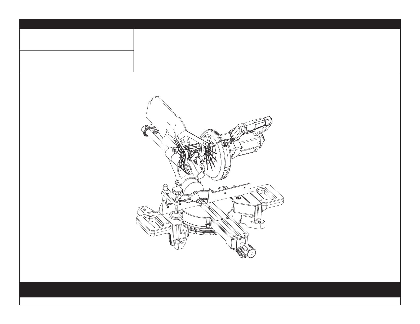
REPAIR SHEET
BRAND
RYOBI
DESCRIPTION
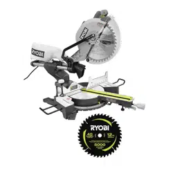
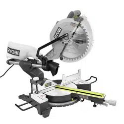
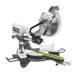
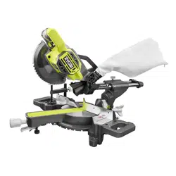
18 Volt 7-1/4 in. Sliding Miter Saw
MODEL NO.
PBT01
ONE WORLD TECHNOLOGIES, INC.
P.O. Box 1288, Anderson, SC 29622 1-800-525-2579 www.ryobitools.com 3-19-21 (Rev:01)
The model number and manufacturing location will be found on a label attached to the product. Always mention this information in all communications regarding this product and when ordering parts.
2
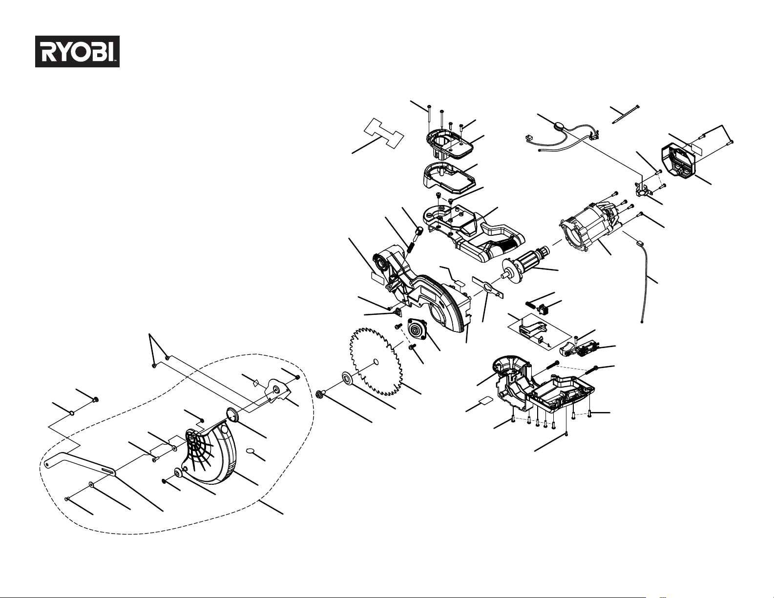
PBT01
FIGURE A
48
29
53
51
29
50
43
47
36
35
34
33
29
32
31
26
28
30
29
29
7
6
5
19
18
17
21
24
25
22
42
41
38
39
29
20
49
40
16
26
4
45
46
23
1
9
10
52
11
12
13
14
2
3
44
27
8
13
15
37
3
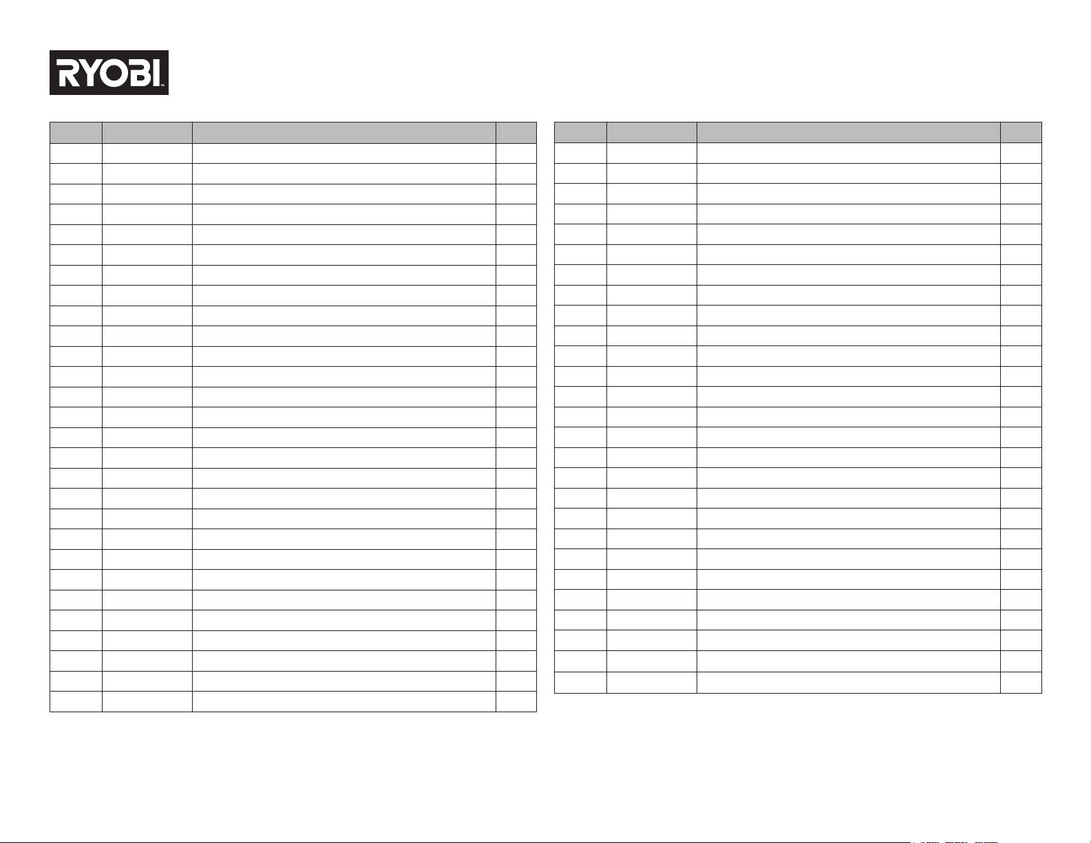
PBT01
KEY NO. PART NO. DESCRIPTION QTY.
1 089240034910 No Hands Label 1
2 089240011008 Wave Spring Washer (ID8) 1
3 089240011029 Screw (M5) 1
4 089240034007 Bolt (M8 x 16 mm, LH) 1
5 089240011086 Outer Flange 1
6 089240071901 7-1/4 in. Blade (40T) 1
7 089240011709 Output Spindle Assembly 1
8 089240071007 Washer (ID4.3 x OD8 X 0.5t) 1
9 089240027081 Lower Guard 1
10 089240011026 Lower Guard Wheel 1
11 089240011025 Spindle Clip 1
12 089240034016 Guard Link Arm 1
13 089240011022 Washer (ID5.3x OD15 x 1.2t) 2
14 089240011023 Link Rivet 1
15 089240011024 Screw (M5 x 16 mm) 1
16 089240011142 Screw (M5 x 16 mm) 2
17 089240011069 Guard Stop Block 1
18 089240011071 Screw (ST4.2 x 10 mm) 1
19 089240071704 Upper Guard Assembly 1
20 089240071008 Hang Tag 1
21 941114320 Upper Guard Logo Label 1
22 089240026902 English Warning Label 1
23 089240011028 Spring 1
24 089240011006 Depth Stop Knob Spring 1
25 089240011005 Depth Stop Knob 1
26 089240071705 Handle Assembly (Inc. Key No. 28) 1
27 089240011905 Screw Direction Label 1
28 089240071904 Data Label 1
PARTS LIST — FIGURE A
KEY NO. PART NO. DESCRIPTION QTY.
29 089240011068 Screw (ST4.2 x 16 mm) 14
30 089240026111 Screw (ST2.9 x 14 mm) 1
31 089240011038 Screw (M5 x 35 mm) 2
32 089240026051 Switch 1
33 089240026703 Trigger Assembly 1
34 089240011065 Arbor Lock Button 1
35 089240011066 Spring 1
36 089240011051 Locking Pole 1
37 089240071706 Rotor Assembly 1
38 089240026046 Screw (ST4.2 x 45 mm) 2
39 532050002 Battery Foot 1
40 089240026034 Screw (M4 x 16 mm) 4
41 089240026044 Battery Base Housing 1
42 089240026043 Screw (M5 x 10 mm) 2
43 089240071711 Stator Assembly 1
44 089240034008 Screw (M5 x 10 mm) 2
45 089240011031 Lock Nut (M5) 1
46 089240034017 Cover Plate (Inc. Key No. 27) 1
47 089240026109 Wire Harness B (Red Wire), Brush 1
48 089240071006 Cable Tie 1
49 089240026041 Wire Harness A (White), Terminal, NTCS and Brush 1
50 089240026056 NTC Bracket 1
51 089240026048 Motor End Cap Assembly (Inc. Key No. 53) 1
52 089240071708 Lower Guard Assembly 1
53 941114321 Motor Housing Logo Label 1
Not Shown:
998000355 Operator’s Manual
4
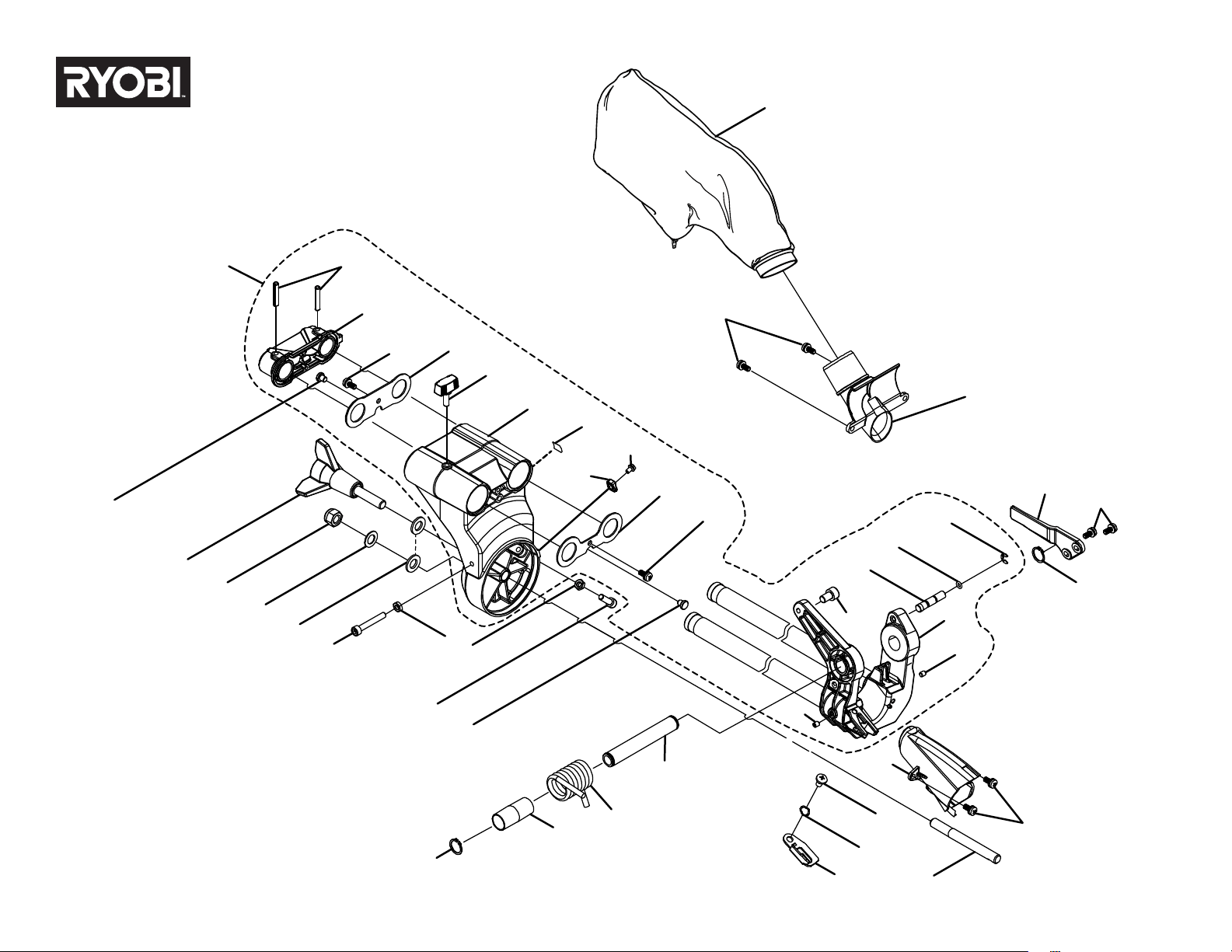
PBT01
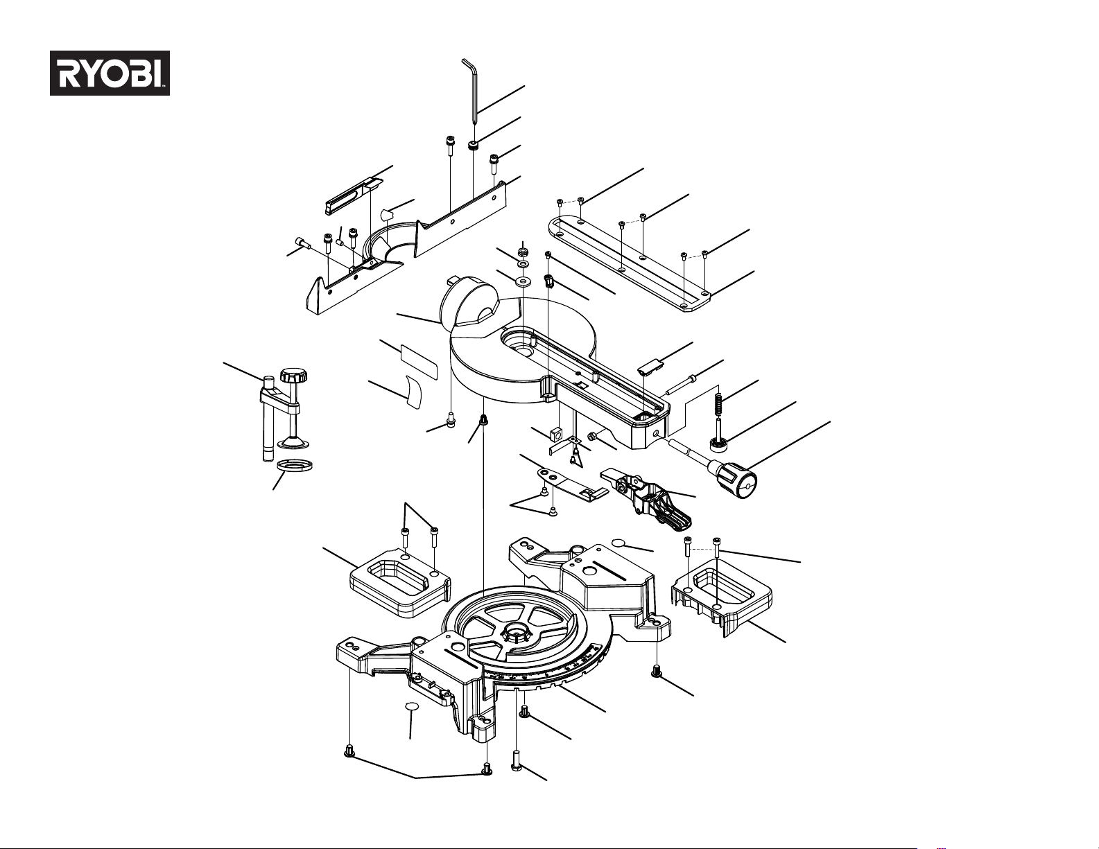
FIGURE B
15
6
16
17
11
28
6
13
27
18
21
20
19
22
6
5
7
10
9
8
6
23
2
36
24
25
1
35
34
33
32
31
30
29
28
27
26
18
12
3
4
14
6
37
5
PBT01
KEY NO. PART NO. DESCRIPTION QTY.
1 089240011107 Slide Tube Lock Knob 1
2 089240011130 Screw (M4 x 8 mm) 1
3 089240034027 Torsion Spring 1
4 089240011010 Shaft Sleeve 1
5 089240011018 Dust Chute A 1
6 089240011104 Screw (M5 x 12 mm) 8
7 089240034026 Shaft 1
8 089240011007 Depth Stop Plate 1
9 089240011008 Wave Spring Washer 1
10 089240011029 Screw 1
11 089240071709 Sliding Assembly (Inc. 1-2, 6, 12, 15-25, & 36) 1
12 089240011019 Pivot Bracket 1
13 089240011016 Crown Finger 1
14 089240011703 Dust Bag Assembly 1
15 089240011099 Linear Bearing Rear Cover 1
16 089240011101 Tube End Cap 1
17 089240011102 Pin 2
18 089240011020 Screw (M5 x 6 mm) 2
19 089832002019 Head Lock Pin 1
PARTS LIST — FIGURE B
KEY NO. PART NO. DESCRIPTION QTY.
20 089240011015 O-Ring 1
21 089240027002 Clip 1
22 089240011017 Screw (M8 x 12 mm) 1
23 089240011108 Linear Bearing Front Cover 1
24 089240011912 Crown Base Arrow Label 1
25 089240011092 Bevel Bracket 1
26 089240011012 Pivot Shaft 1
27 089240011011 Retaining Ring 2
28 089240011100 Bumper Pad 2
29 089240011110 Screw (M6 x 20 mm) 1
30 089240011093 Nut (M6) 2
31 089240011094 Screw (M6 x 40 mm) 1
32 089240011095 Washer (ID10.5 x OD20 x 2t) 2
33 089240011096 Washer (ID10 x OD18.8 x 1t) 1
34 089240011097 Lock Nut (M10) 1
35 089240011098 Bevel Lock Knob 1
36 089240011109 Bevel Indicator 1
37 089240011002 Dust Chute B 1
6
PBT01
FIGURE C
4
3
5
4
1
4
6
7
25
26
27
28
29
6
7
8
9
10
3
17
18
19
20
30
17
34
35
35
35
36
39
21
22
38
23
37
24
33
32
31
16
15
14
12
13
11
2

7
PBT01
KEY NO. PART NO. DESCRIPTION QTY.
1 089240071701 Base Assembly (Inc. Key No. 3) 1
2 089240011927 Clamp Pad 1
3 089240034910 No Hands Label 2
4 089240011140 Rubber Feet 4
5 089240034034 Bolt (M8 x 16 mm, LH) 1
6 089240034014 Side Handle 2
7 089240034013 Bolt (M6 x 25 mm) 4
8 089240011132 Screw (M6 x 16 mm) 2
9 089240011131 Detent Spring Plate 1
10 089240011128 Square Nut (M10) 1
11 089240011113 Screw (M6 x 16 mm) 1
12 089240071702 Table Assembly (Inc. Key Nos. 14-16) 1
13 089240071710 Clamp Assembly (Inc. Key No. 2) 1
14 089240011913 Sliding Cut Direction Label 1
15 089240071903 Bevel Scale Label 1
16 089240011141 Friction Mat 10
17 089240011130 Screw (M4 x 8 mm) 3
18 089240011129 Miter Lock Spacer 1
19 089240011133 Lock Nut (M6) 1
20 089240011713 Miter Detent Release Lever Assembly 1
PARTS LIST — FIGURE C
KEY NO. PART NO. DESCRIPTION QTY.
21 089240011091 Spanner Holder 1
22 089240011090 Inner Hexagon Spanner 1
23 089240034036 Sliding Fence 1
24 089240034023 Thumb Screw 1
25 089240034712 Miter Lock Handle Assembly 1
26 089240011136 Table Foot 1
27 089240011135 Spring 1
28 089240011124 Screw 1
29 089240011121 Knob Cover 1
30 089240011118 Miter Indicator 1
31 089240011117 Washer (ID8 x OD22 x 3t) 1
32 089240011116 Washer (ID8 x OD16 x 1.6t) 1
33 089240034033 Lock Nut (M8) 1
34 089240011119 Throat Plate 1
35 089240011120 Screw (M4 x 8 mm) 6
36 089240071703 Fixed Fence Assembly (Inc. Key No. 38) 1
37 089240034012 Screw (M6 x 10 mm) 1
38 089240071902 Warning Label 1
39 089240011088 Screw (M6 x 25 mm) 4
8
PBT01
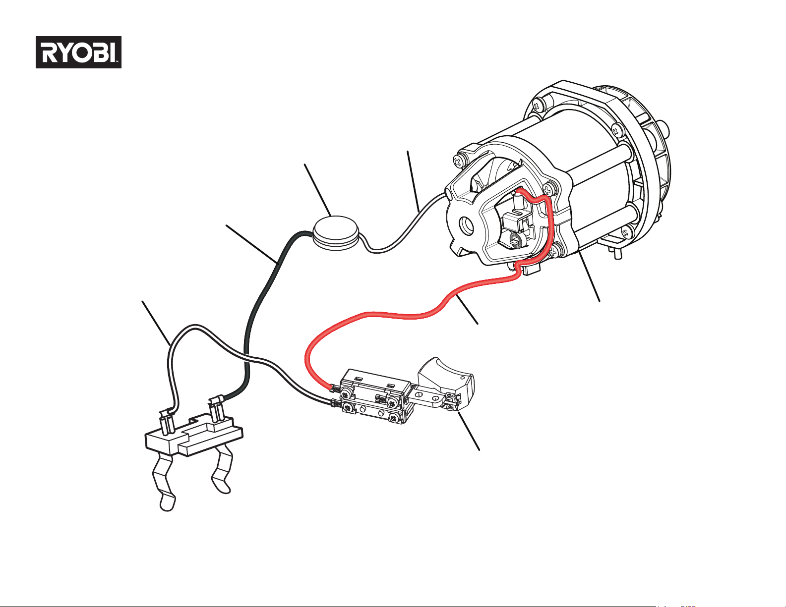
WIRING DIAGRAM
BLACK BRUSH
LEAD
NTC
(CURRENT LIMITER)
SWITCH
RED BRUSH
LEAD
MOTOR
WHITE
LEAD
WHITE BRUSH
LEAD