English
Stock Nos.
2645/2655
26945 /26955
Fran¢ais
N°Sde stock
2645 /2655
26945 /26955
•Do not run pump dry or leave unattended whde running.
The pump must be unplugged immediately once the
water is pumped away.
• Use only 1/2" or larger garden hose.
• If pump is stopped and restarted whde pumping, an air
blockage may form in the discharge hose. To restart
pumping, unplug the pump and drain all water from the
hose.
• Not recommended for use m fountains or ponds with
fish
• If installed with an extension cord, be sure the cord is 14
gauge wire.
• Regularly inspect pump inlet and clean away any debris.
Ne faites pas fonct_onner la pompe _ sec et ne la laissez
pas sans surveillance, pendant qu'elle fonctionne. La
pompe dolt _tre imm_diatement d_branch_e Iorsque
toute l'eau a _t_ pomp_e.
N'utlhsez qu'un tuyau d'arrosage de 1/2 de pouce de
dlam_tre ou plus gros.
Si la pompe est arr_t_e et red_marr_e alors qu'eile fonc-
tionnait, un bouchon d'air peut se former dans le tuyau
de refoulement. Pour recommencer le pompage,
d_branchez la pompe et vJdez toute I'eau du tuyau.
Utdlsation non recommand_e avec les r_servolrs ou [es
6tangs dans lesquels iI y a des polssons.
Si un cordon prolongateur est ut_l_s_ pour ['ahmentatLon
en courant, assurez-vous que les conducteurs du cordon
prolongateur sont du cahbre 14.
tnspectez r_guh_rement ['admission de la pompe et
enlevez tousles d_bris.
(800) 432-4029 (800) 432-4029
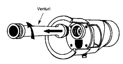
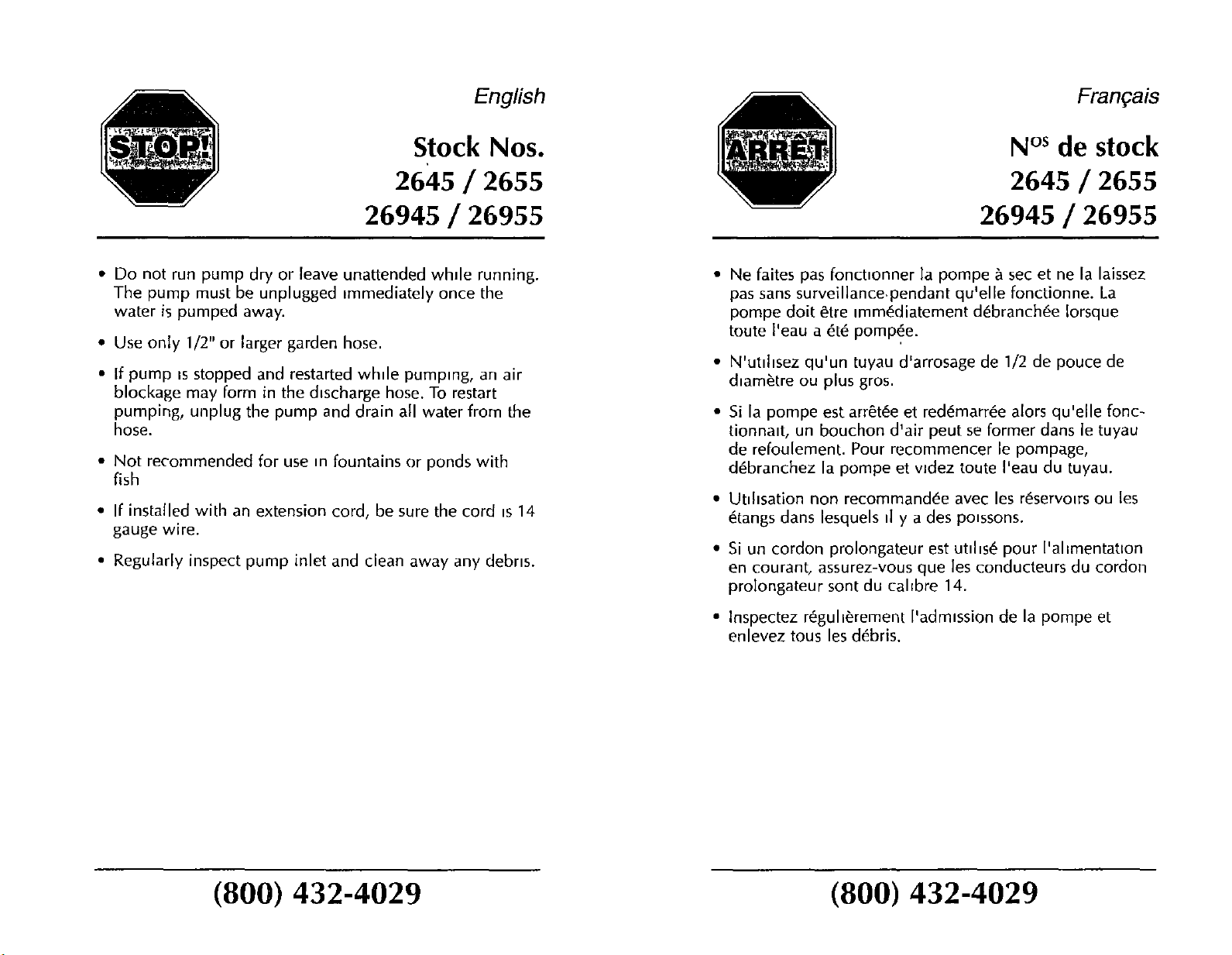
Nozzle/Venturi Replacement and Cleaning
Venturi
5/8" Socket
Nozzle
Figure 1 Ejector Body
Figure 2 insert
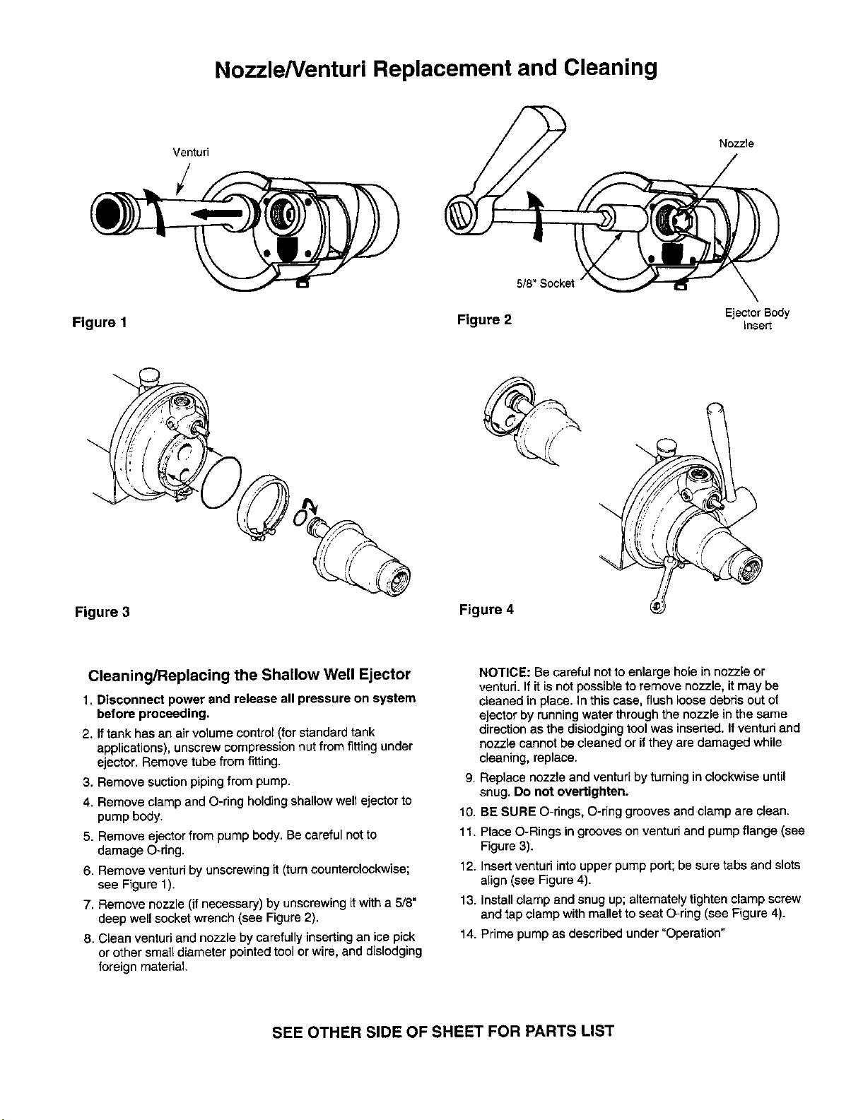
Figure 3 Figure 4
Cleaning/Replacing the Shallow Well Ejector
1. Disconnect power and release all pressure on system
before proceeding.
2. Iftank has an air volume control (for standard tank
applications), unscrew compression nut from fitting under
ejector. Remove tube from fitting.
3, Remove suction pipingfrom pump.
4. Remove clamp and O-ring holdingshallow well ejector to
pump body.
5. Remove ejector from pump body. Be careful not to
damage O-ring.
6. Remove ventud by unscrewing it (turnoountemlockwise;
see Figure 1).
7, Remove nozzle (if necessary) by unscrewing it with a 5/8"
deep well socket wrench (see Figure 2).
8, Clean venturi and nozzle by carefully inserting an ice pick
or other small diameter pointed tool or wire, and dislodging
foreign material
NOTICE: Be careful not to enlarge hole in nozzle or
venturi. If itis not possible to remove nozzle, it may be
cleaned in place. In this case, flush loose debris out of
ejector by running water through the nozzle in the same
direction as the dislodging tool was inserted. If venturi and
nozzle cannot be cleaned or if they are damaged while
cleaning, replace.
9. Replace nozzle and venturi by turning in clockwise until
snug. Do not overtighten.
10. BE SURE O-rings, O-ring grooves and clamp are clean.
11. Place O-Rings in grooves on venturi and pump flange (see
Figure 3).
12. Insert venturi into upper pump port; be sure tabs and slots
align (see Figure 4).
13. Install clamp and snug up; alternately tighten clamp screw
and tap clamp with mallet to seat O-ring (see Figure 4).
14. Prime pump as described under "Operation"
SEE OTHER SIDE OF SHEET FOR PARTS LIST
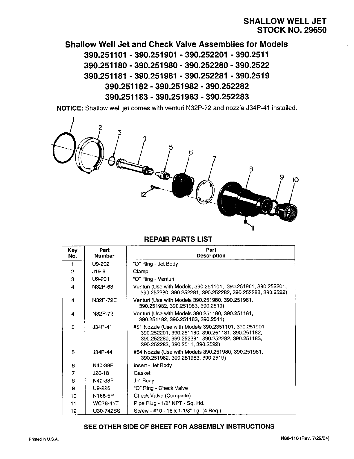
SHALLOW WELL JET
STOCK NO. 29650
Shallow Well Jet and Check Valve Assemblies for Models
390,251101 -390,251901 -390.252201 -390,2511
390.251180 -390,251980 -390.252280 -390.2522
390,251181 -390.251981 -390,252281 -390.2519
390,251182 - 390.251982 -390.252282
390.251183 -390,251983 -390,252283
NOTICE: Shallow well jet comes with venturi N32P-72 and nozzle J34P-41 installed.
I25
8
9IO
Key Part
No. Number
1U9-202
2 J19-6
3U9-201
4 N32P-63
4
4
5
6
7
8
9
10
11
12
REPAIR PARTS LIST
N32P-72E
N32P-72
J34P-41
J34P-44
N40-39P
J20-18
N40-38P
U9-226
N166-5P
WC78-41T
U30-742SS
Part
Description
"O" Ring -Jet Body
Clamp
"O" Ring - Venturi
Venturi (Use with Models, 390.251101, 390.251901,390.252201,
390.252280, 390.252281,390.252282, 390.252283, 390.2522)
Venturi (Use with Models 390.251980, 390.251981,
390.251982, 390.251983, 390.2519)
Venturi (Use with Models 390.251180, 390.251181,
390.251182, 390.251183, 390.2511 )
#51 Nozzle (Use with Models 390.2351101,390.251901
390.252201, 390.251180, 390.251181,390.251182,
390.252280, 390.252281, 390.252282, 390.251183,
390.252283, 390.2511,390.2522)
#54 Nozzle (Use with Models 390.251980, 390.251981,
390.251982, 390.251983, 390.2519)
Insert - Jet Body
Gasket
Jet Body
"O" Ring - Check Valve
Check Valve (Complete)
Pipe Plug - 1/8" NPT - Sq. Hd.
Screw - #10 - 16 x 1-1/8" Lg. (4 Req.)
SEE OTHER SIDE OF SHEET FOR ASSEMBLY INSTRUCTIONS
Printedin U.S.A. N80-110 (Rev. 7/29/04)